40345 - Machine de transformation alimentaire Maturmeat - Free user manual and instructions
Find the device manual for free 40345 Maturmeat in PDF.

User questions about 40345 Maturmeat
0 question about this device. Answer the ones you know or ask your own.
Ask a new question about this device
Download the instructions for your Machine de transformation alimentaire in PDF format for free! Find your manual 40345 - Maturmeat and take your electronic device back in hand. On this page are published all the documents necessary for the use of your device. 40345 by Maturmeat.
USER MANUAL 40345 Maturmeat
FOOD TRANSFORMATION SYSTEMS
MATURMEAT®
USER AND MAINTENANCE MANUAL
INDEX
MATURMEATT™
Pag. 3 1.1 General Safety Warnings
Pag. 4 1.2 Identification Data & Data Plate
Pag. 4 1.3 Standard Accessories
Pag. 5 1.4 Maturmeat™ Diagram
Pag. 6 1.5 Receipt Inspection
Pag. 6 1.6 Installation
CLIMATOUCH®
Pag. 8 2.1 Using Climatouch® For The First Time
Pag. 9 2.2 Starting The Test Recipe
Pag. 10 2.3 Recipe Screen Defined
Pag. 12 2.4 Starting a Default Climatic Recipe
Pag. 12 2.5 Modifing Recipe Parameters
Pag. 13 2.6 Checking HACCP-Performance as Line Data
Pag. 14 2.7 Checking HACCP-Performance as a Graph
Pag. 15 2.8 New Recipe Parameters Defined
Pag. 16 2.9 Creating and Saving New Recipes
Pag. 19 2.10 Starting a Saved Recipe
Pag. 19 2.11 Forcing Aroma
MAINTANENCE
Pag. 20 3.1 Calibrating Standard Probes
Pag. 21 3.2 Calibrating pH Probe
Pag. 23 3.3 Fumotic's supply tanks
Pag. 23 3.4 Water Filter
Pag. 24 3.5 Fumotic® Rear View
Pag. 24 3.6 Fumotic® Front View
Pag. 25 3.7 How to connect direct waterline to Fumotic®
Pag. 25 3.8 How to remove calcium from Fumotic®
Pag. 26 3.9 Cleaning Maturmeat™
Pag. 27 3.10 Changing the Light
Pag. 27 3.11 Emptying drain tray
Pag. 28 3.12 Temperature Maintenance
Pag. 29 3.13 Humidity Maintenance
Pag. 30 3.14 Firmware Update Climatouch®
Pag. 32 3.15 Firmware Update PLC's
Pag. 34 3.16 Troubleshooting
TECHNICAL INFORMATION & DATA
Pag. 36 4.1 System Variables
Pag. 42 4.2 Maturmeat™ Specifications
Pag. 42 4.3 Climatouch® Specifications
Pag. 43 4.4 Functions Managed By Climatouch®
Pag. 44 4.5 PLC A Specifications
Pag. 45 4.6 PLC B Specifications
Pag. 46 4.7 Electrical Schematic 100kg
Pag. 47 4.8 Electrical Schematic 150kg
Pag. 48 4.9 Electrical Schematic 200kg
Pag. 49 4.10 Electrical Schematic Twin 100+100kg Table 1
Pag. 50 4.11 Electrical Schematic Twin 100+100kg Table 2
Pag. 51 4.12 Electrical Schematic Fumotic® 60/100/150/200kg
Pag. 52 4.13 Electrical Schematic Fumotic® Twin 100+100kg
WARRANTY & DISPOSAL
Pag. 53 5.1 Limited Warranty
Pag. 54 5.2 Proper Disposal
Your safety and the safety of others are very important.
We have provided many important safety messages in this manual and on your appliance. Always read and obey all safety messages.

natural_image
Yellow triangular warning sign with black exclamation mark (no text or symbols beyond the icon)This is the safety alert symbol.
This symbol alerts you to potential hazards that can kill or hurt you and others.
All safety messages will follow the safety alert symbol and the word
"Danger." This word mean:

DANGER
Youcanbekilledorseriouslyinjuredifyoudon'tfollow instructions.
All safety messages will tell you what the potential hazard is, tell you how to reduce the chance of injury, and tell you what can happen if the instructions are not followed.
IMPORTANT SAFETY INSTRUCTIONS
WARNING: To reduce the risk of fire, electric shock, or injury when using your Maturmeat™, follow these basic precautions:
■ After unpacking, make sure the machine is complete and free from damage. If in doubt, do not use and contact a qualified technician.
- Check that the information on data plate corresponds with the main power supply.
- This appliance must be used exclusively for the purpose for which it was made. Any other use is considered improper and therefore dangerous.
- The machine must be handled only by trained personnel.
- For any eventual repairs please contact an authorized dealer and/or technician, use only original replacement parts.
- Do not wash the machine with high pressure water jets.
- Fumotic® flavoring/humidification processes and humidity probes are not to be used below -3^ (minus three degrees centigrate), and are excluded from operation and consequently unusable and unreliable, the manufacture is not liable for programming differing from the aforementioned
- All working parameters described in brochures, price lists, refer to programming and/or functionality to achieve a single process separately, and not connected or linked.
- Arredo Inox Srl assumes no responsibility for any errors that may appear in this document. In no event shall Arredo Inox Srl be liable for incidental or consequential damages arising from use of this document or the software and hardware described in this document.
- The information contained within the user manual is subject to change without notice and should not be construed as a commitment by Arredo Inox Srl.
- The default climatic recipes programmed in your Maturmeat™ are suggested and are modifiable by the user, they are meant to be used a guide.
■ Always shut down power to the unit before attempting any work on the unit, other than the exclusive purpose for which it was made. - Not respecting any of the aforementioned points may compromise the safety of the machine and or the user.
SAVE THESE INSTRUCTIONS
This manual replaces all previous versions, and contains up to date information on procedures and settings, with the exception of electrical drawings (find production dates on each drawing)
This document and parts thereof must not be reproduced or copied without Arredo Inox Srl's written permission, and contents thereof must not be imparted to a third party nor be used for any unauthorized purpose. Contravention will be prosecuted.
1.2
IDENTIFICATION DATA & DATA PLATE
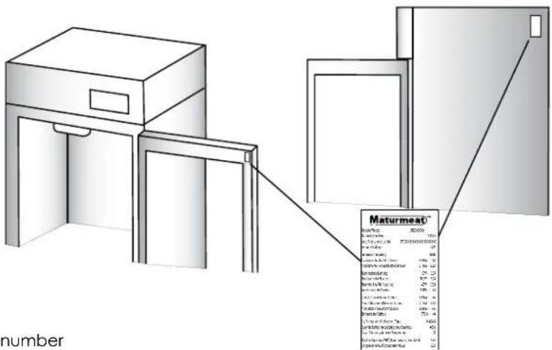
The serial tag is a permanently affixed sticker on which is recorded vital electrical and refrigeration data about your Maturmeat™ product, as well as the model and serial number. There are two data plates on each unit, they can be found on the inside top corner of the doorframe and on the top corner on the right hand side of the body. When contacting the manufacturer, please provide the serial number and production lot number found on your cabinet or on the conformance certificate.
text_image
Maturmeat* Number: 302000 Price per unit: $10.00 Cost per unit: $7.50 Price per unit: $6.00 Maturity: 12.00 Balance at the end of the year: 4800 - 12 Balance at the end of the year: 1,900 - 12 Balance at the end of the year: 225 - 12 Balance at the end of the year: 800 - 12 Balance at the end of the year: 450 - 12 Balance at the end of the year: 150 - 12 Balance at the end of the year: 1,500 - 12 Balance at the end of the year: 1,700 - 12 Balance at the end of the year: 1,800 - 12 Balance at the end of the year: 2,000 - 12 Balance at the end of the year: 2,200 - 12 Balance at the end of the year: 2,400 - 12 Balance at the end of the year: 2,600 - 12 Balance at the end of the year: 2,800 - 12 Balance at the end of the year: 3,000 - 12 Balance at the end of the year: 3,200 - 12 Balance at the end of the year: 3,400 - 12 Balance at the end of the year: 3,600 - 12 Balance at the end of the year: 3,800 - 12 Balance at the end of the year: 4,000 - 12 Balance at the end of the year: 4,200 - 12 Balance at the end of the year: 4,400 - 12 Balance at the end of the year: 4,600 - 12 Balance at the end of the year: 4,800 - 12 Balance at the end of the year: 5,000 - 12 Balance at the end of the year: 5,200 - 12 Balance at the end of the year: 5,400 - 12 Balance at the end of the year: 5,600 - 12 Balance at the end of the year: 5,800 - 12 Balance at the end of the year: 6,000 - 12 Balance at the end of the year: 6,200 - 12 Balance at the end of the year: 6,400 - 12 Balance at the end of the year: 6,600 - 12 Balance at the end of the year: 6,800 - 12 Balance at the end of the year: 7,000 - 12 Balance at the end of the year: 7,200 - 12 Balance at the end of the year: 7,400 - 12 Balance at the end of the year: 7,600 - 12 Balance at the end of the year: 7,800 - 12 Balance at the end of the year: 8,000 - 12 Balance at the end of the year: 8,200 - 12 Balance at the end of the year: 8,400 - 12 Balance at the end of the year: 8,600 - 12 Balance at the end of the year: 8,800 - 12 Balance at the end of the year: 9,000 - 12 Balance at the end of the year: 9,200 - 12 Balance at the end of the year: 9,400 - 12 Balance at the end of the year: 9,600 - 12 Balance at the end of the year: 9,800 - 12 Balance at the end of the year: 10,000 - 12 Balance at the end of the year: 10,200 - 12 Balance at the end of the year: 10,400 - 12 Balance at the end of the year: 10,600 - 12 Balance at the end of the year: 10,800 - 12 Balance at the end of the year: 11,000 - 12 Balance at the end of the year: 11,200 - 12 Balance at the end of the year: 11,400 - 12 Balance at the end of the year: 11,600 - 12 Balance at the end of the year: 11,800 - 12 Balance at the end of the year: 12,000 - 12 Balance at the end of the year: 12,200 - 12 Balance at the end of the year: 12,400 - 12 Balance at the end of the year: 12,600 - 12 Balance at the end of the year: 12,800 - 12 Balance at the end of the year: 13,000 - 12 Balance at the end of the year: 13,200 - 12 Balance at the end of the year: 13,400 - 12 Balance at the end of the year: 13,600 - 12 Balance at the end of the year: 13,800 - 12 Balance at the end of the year: 14,000 - 12 Balance at the end of the year: 14,200 - 12 Balance at the end of the year: 14,400 - 12 Balance at the end of the year: 14,600 - 12 Balance at the end of the year: 14,800 - 12 Balance at the end of the year: 15,000 - 12 Balance at the end of the year: 15,200 - 12 Balance at the end of the year: 15,400 - 12 Balance at the end of the year: 15,600 - 12 Balance at the end of the year: 15,800 - 12 Balance at the end of the year: 16,000 - 12 Balance at the end of the year: 16,200 - 12 Balance at the end of the year: 16,400 - 12 Balance at the end of the year: 16,600 - 12 Balance at the end of the year: 16,800 - 12 Balance at the end of the year: 17,000 - 12 Balance at the end of the year: 17,200 - 12 Balance at the end of the year: 17,400 - 12 Balance at the end of the year: 17,600 - 12 Balance at the end of the year: 17,800 - 12 Balance at the end of the year: 18,000 - 12 Balance at the end of the year: 18,200 - 12 Balance at the end of the year: 18,400 - 12 Balance at the end of the year: 18,600 - 12 Balance at the end of the year: 18,800 - 12 Balance at the end of the year: 19,000 - 12 Balance at the end of the year: 19,200 - 12 Balance at the end of the year: 19,400 - 12 Balance at the end of the year: 19,600 - 12 Balance at the end of the year: 19,800 - 12 Balance at the end of the year: 20,000 - 12 Balance at the end of the year: 20,200 - 12 Balance at the end of the year: 20,400 - 12 Balance at the end of the year: 20,600 - 12 Balance at the end of the year: 20,800 - 12 Balance at the end of the year: 21,000 - 12 Balance at the end of the year: 21,200 - 12 Balance at the end of the year: 21,400 - 12 Balance at the end of the year: 21,600 - 12 Balance at the end of the year: 21,800 - 12 Balance at the end of the year: 22,000 - 12 Balance at the end of the year: 22,200 - 12 Balance at the end of the year: 22,400 - 12 Balance at the end of the year: 22,6O-3/- Balance at that point: $3.5M (in € million) 3.5M (out-of-use) :3.5M (in € million) 3.5M (out-of-use) :3.5M (in € million) 3.5M (out-of-use) :3.5M (in € million) 3.5M (out-of-use) :3.5M (in € million) 3.5M (out-of-use) :3.5M (in € million) $3.5M (in € million) 3.5M (out-of-use) :3.5M (in € million) 3.5M (out-of-use) :3.5M (in € million) 3.5M (out-of-use) :3.5M (in € million) 3.5M (out-of-use) :3.5M (in € million) 3.5M(out-of-use) :3.5M (in € million) 3.5M(out-of-use) :3.5M (in € million) 3.5M(out-of-use) :3.5M (in € million) 3.5M(out-of-use) :3.5M (in € million) 3.5M(out-of-use) :3.5M (in € million) Total amount in euro for each quarter. Number as a percentage or percentage per quarter. Number as a percentage or percentage per quarter. Number as a percentage or percentage per quarter. Number as a percentage or percentage per quarter. Number as a percentage or percentage per quarter. Number as a percentage or percentage per quarter. Number as a percentage or percentage per quarter. Number as a percentage or percentage per quarter. Number as a percentage or percentage per quarter. Number as a percentage or percentage per quarter. Number as a percentage or percentage per quarter. Number as a percentage or percentage per quarterly. Number as a percentage or percentage per quarterly. Number as a percentage or percentage per quarterly. Number as a percentage or percentage per quarterly. Number as a percentage or percentage per quarterly. Number as a percentage or percentage per quarterly. Number as a percentage or percentage per quarterly. Number as a percentage or percentage per quarterly. Number as a percentage or percentage per quarterly. Number as a percentage or percentage per quarterly. Number as a percentage or percentage per quarterly. Number as a percentage or percentage per quarterly。 Number as a percentage or percentage per quarterly. Number as a percentage or percentage per quarterly. Number as a percentage or percentage per quarterly. Number as a percentage or percentage per quarterly. Number as a percentage or percentage per quarterly. Number as a percentage or percentage per quarterly. Number as a percentage or percentage per quarterly. Number as a percentage or percentage per quarterly. Number as a percentage or percentage per quarterly. Number as a percentage or percentage per quarterly. Number as a percentage or percentage per quarterly. Percentage as a percentage or percentage per quarterly. Percentage as a percentage or percentage per quarterly. Percentage as a percentage or percentage per quarterly. Percentage as a percentage or percentage per quarterly. Percentage as a percentage or percentage per quarterly. Percentage as a percentage or percentage per quarterly. Percentage as a percentage or percentage per quarterly. Percentage as a percentage or percentage per quarterly. Percentage as a percentage or percentage per quarterly. Percentage as a percentage or percentage per quarterly. Percentage as a percentage or percentage per quarterly. Percentageas a % (in %) from one quarter to three quarters. Percentage as a % (in %) from two quarters to three quarters. Percentage as a % (in %) from three quarters to four quarters. Percentage as a % (in %) from four quarters to five quarters. Percentage as a % (in %) from six quarters to seven quarters. Percentage as a % (in %) from eight quarters to nine quarters. Percentage as a % (in %) from ten quarters to ten quarters. Percentage as a % (in %) from ten quarters to ten quarters. Percentage as a % (in %) from ten quarters to ten quarters. Percentage as a % (in %) from ten quarters to ten quarters. Percentage as a % (in %) from ten quarters to ten quarters. Percentage as a % (in %) from ten quarters to ten quarters. Percentage as a % (in %) from ten quarters to ten quarters. Percentage as a % (in %) % (in %) % (in %) % (in %) % (in %) % (in %) % (in %) % (in %) % (in %) % (in %) % (in %) % (in %) % (in %) % (in %) % (in %) % (in %) % (in %) % (in %) % (in %) % (in %) % (in %) % % (in %) % (in %) % (in %) % (in %) % (in %) % (in %) % (in %) % (in %) % (in %) % (in %) % (in %) % (in %) % (in %) % (in %) % (in %) % (in %) % (in %) % (in %) % (in %) % (in %)Maturmeat™
| Modello/Model: | STG/XXXXXX |
| Matricola/Serial No: | 51XXX |
| Lotto Produzione/ Lot No: | STG/XXXXXX/XXXXXX/XXXXXX |
| Tensione/Voltage: | 230 V |
| Frequenza/Frequency: | 60Hz |
| Assorbimento Max/Max Power: | 3420W - 14A |
| Assorbimento Nominale/Rated Power: | 2100W - 9.3A |
| Illuminazione/Lighting | 30W - 0.3A |
| Riscaldamento/Heaters: | 1500W - 6.2A |
| Ricambio Aria/Air Recycling: | 40W - 0.5A |
| Raffreddamento/Cooling: | 670W - 4A |
| Umidificazione/Humidification: | 1250W - 6A |
| Deumidificazione/Dehumidification: | 2100W - 9.4A |
| Aromatizzazione/Aromatization: | 1250W - 6A |
| Sbrinamento/Defrost: | 770W - 4A |
| Gas Refrigerante/Refrigerant Type: | R 404 A |
| Quantità Refrigerante/Refrigerant Quantity: | 400g |
| Classe Climatica/Ambient Temperature: | ST |
| Max Cort.Operativa (MRA)/Max Operating Curr. (MRA) | 2.8A |
| Compressore (RLA)/Compressor (RLA) | 16.5A |

CE MADE IN ITALY
1) Brand
2) Model
3) Serial number
4) Production lot number
5) Voltage
6) Frequency
7) Max Power
8) Nominal Power
9) Power usage for lighting
10) Power usage during heating
11) Power usage during air cycling
12) Power usage during cooling
13) Power usage during humidification
14) Power usage during dehumidification
15) Power usage during flavouring
16) Power usage during defrosting
17) Refrigerant type
18) Refrigerant quantity
19) Climatic class
20) Max operating current
21) Compressor Rated load Amps
22) Manufacturer
23) Certification
24) Country of Origin
STANDARD ACCESSORIES
The following items are included with your Maturmeat™. Contact your dealer should any of the following be missing
No. 3 temperature probes;
No. 1 humidity probe;
No. 1 closed loop connector (for direct waterline see page 25);
No. 1 user manual;
No. 1 warranty registration card;
No. 1 drain tray;
No. 1 drain hose;
No. 5 guide sets (L&R);
No. 5 stainless steel shelves

text_image
1 2 3 4 5 6 7 8 9 10 11 12 13 14 15 16 Number Description Quantity 1 Tanks water/aroma 2 2 Condensing Unit 1 3 Condensing Unit 2| Number | Description Quantity | |
| 1 | Tanks water/aroma | 2 |
| 2 | Condensing Unit | 1 |
| 3 | Fumotic® | 1 |
| 4 | Transformer | 2 |
| 5 | PLC | 2 |
| 6 | Touch Controller | 1 |
| 7 | Evaporator | 1 |
| 8 | Internal Light | 1 |
| 9 | Humidity Probe | 1 |
| 10 | Ambient Probe | 1 |
| 11 | Steam Output | 1 |
| 12 | Unibody Frame | 1 |
| 13 | Adjustable Legs | 4 |
| 14 | Molding w/Heating | 1 |
| 15 | Drain Tray | 1 |
| 16 | Door w/Resistance | 1 |
| 17 | Door Hinge | 2 |

DANGER
Gas Exposure Do not damage the cooling system as it contains R404a refrigerant, which can cause injury, burns and frostbite.
1.5
RECEIPT INSPECTION
All Maturmeat™ units are factory tested for performance and are free from defects when shipped. The utmost care has been taken in crating this product to protect against damage in transit.
You should carefully inspect your Maturmeat™ unit for damage during delivery, even if the crate is free from damage. If damage is detected, you should save all the crating materials and make note on the carrier's Bill Of Lading describing this. A freight claim should be filed immediately. If damage is subsequently noted during or immediately after installation, contact the respective carrier and file a freight claim. Under no condition may a damaged unit be returned without first obtaining written permission (return authorization).
1.6
INSTALLATION

DANGER
Excessive Weight Hazard Use two or more people to move and install your Maturmeat™. Failure to do so can result in back or other injury.
natural_image
Illustration showing a hand holding a curved object next to a flat-screen monitor and a 3D block (no text or symbols)
DANGER
Keep all packaging away from children

DANGER
Electrical Hazard Never connect power to unit via extension cord or adapter, this can cause damage to the system and/or start a fire.
LOCATION:
Select a proper location away from extreme heat or cold. Space above the unit should allow for breathability to the condensing unit and access to the Water/Aroma tanks. Allow enough clearance between the unit and the side wall in order to allow the doors to fully open.
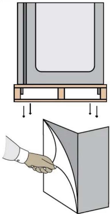
PACKAGING:
The unit is shipped from the factory strapped to a sturdy wooden pallet and protected by MDF crating. The crating is attached to the pallet with nails and several screws. These should first be removed to avoid scratching the unit when lifting off the crating. To remove the Maturmeat™ from the wooden pallet start by cutting free the nylon bands. There are 4 bolts connecting the Maturmeat™ to the pallet, remove them to release the Maturmeat™ from the pallet.
Most exterior surfaces have a protective vinyl covering to prevent scratching during manufacturing, shipping, and installation, remove after installation and discard.
NOTE: DO NOT LAY THE UNIT ON ITS SIDE/BACK/FRONT DURING TRANSPORTATION OR INSTALLATION.
POWER CORD:
An attached power cord is provided without plug, shipped coiled inside the compressor compartment. For your safety and protection, have the installer connect the proper plug for your country by checking with the information on the data plate. Connect only to an appropriate dedicated 20 amp outlet.
POWER SUPPLY:
The supply voltage should be checked prior to connection to be certain that proper voltage for the cabinet wiring is available (refer to the data plate for the correct unit voltage). Make connections in accordance with local electrical codes. Use qualified electricians.
Use of a separate, dedicated circuit is required.
Size wiring to handle indicated load and provide necessary overcurrent protector in circuit (see amp requirements on the unit's data plate).
natural_image
Diagram showing a mechanical assembly with a rectangular block, angled surfaces, and a textured wall (no text or symbols)
DANGER
Electrical Shock Hazzard if any damage to wiring is found, do not touch and contact your local service point. Failure to do so can result in serious injury or death.
text_image
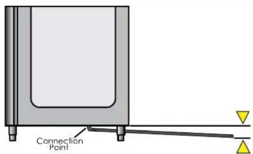
Connection PointELECTRICAL SCHEMATICS:
Refer to the electrical schematics on page 46-52 for any service work performed on the unit. Should you require a new one, please contact Maturmeat™ Service at produzione@arredoinox.it, and provide serial number of the unit involved.
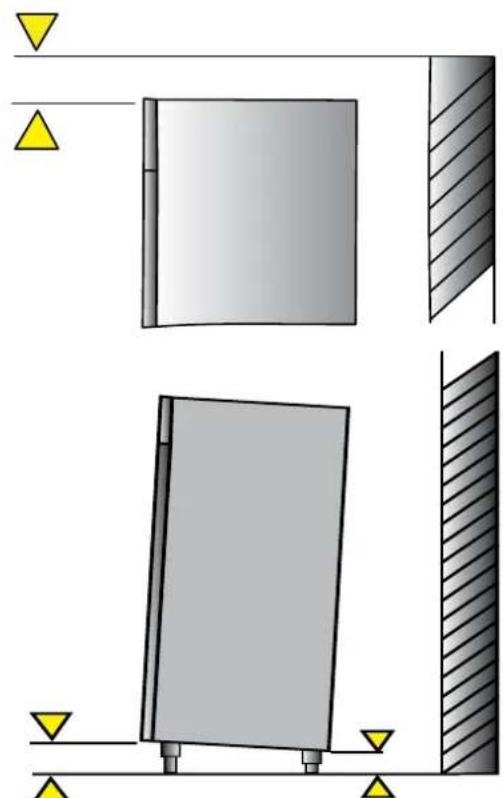
CLEARANCE:
To assure optimum performance of your Maturmeat™ the condensing unit MUST have an adequate supply of air for cooling purposes. The operating location must have 30 cm (12") minimum clearance from the top of the Maturmeat™ to the ceiling.
Select a working location away from extreme heat or cold. The Maturmeat™ is designed to operate in temps of 89°F (32°C) or less. Locate the unit so that air drafts (such as heat, A/C or ventilation) do not blow on or over the top of the Maturmeat™.
ADJUSTING LEGS:
Unit includes 4 factory installed (except 100kg model). The ideal position for the unit should be that it leans towards the back, to allow for proper door closure. Adjust the leg by turning the lower portion of the leg. MATC100TF units will include 4 legs and 16 bolts packed inside the unit, these will need to be mounted and then adjusted.
VISUAL TEST:
Check the top of the unit making sure nothing has moved, shifted or loosened during transport. Check that all wires to PLC's are firmly connected, check lines on the condensing unit, check Fumotic® and lines to tanks.
Disconnect power to unit before performing visual test
PREPARE UNIT:
Fill the water tank with water to avoid false alarm. Slide the drain tray on the tracks underneath the unit, or set up the drain hose to connect to a floor or dedicated drainage system. Make sure that the end of the drain hose is a minimum of 5cm lower than the connection point. Before starting the test recipe, wipe down the inside of the unit in contact with food using a cloth or sponge, water and a non aggressive/non abrasive cleaner (for more information on cleaning, refer to page 26).
TEST RECIPE:
Maturmeat™ has a test recipe programmed under the My Recipe category. The test recipe must be run to ensure the Maturmeat™ performs all its functions. This is to prevent loss of product on first use. To set test recipe see page 9
REGISTER YOUR UNIT:
In order to validate your warranty please follow the link, http://www.stagionello.it/authentication.php?back=my-account.php
2.1
USING CLIMATOUCH® FOR THE FIRST TIME
After a successful installation and with power to your Maturmeat™, the Climatouch® controller will start up automatically on the Welcome page.
The Welcome page allows you to select the language, and displays Firmware version installed.
Note: Information may be displayed in Italian for the first time
From this screen, select the language you would like to use. You can change language at anytime by pressing the backward arrow from the Home page.
If needed, come back to the welcome page to check your firmware version, which can be found in the bottom left corner of the screen.
After selecting your language, you will land on the date and time page, where you can adjust the data should you need to.
To adjust the date or time, press the Set icon beside the corresponding field.
Use the up and down arrows above and below the numbers to adjust the month, day and year. Press the check mark to save and exit.
Use the up and down arrows above and below the numbers to adjust the hour and minute. Press the check mark to save and exit.

text_image
Welcome 15/05/2014 08:05 V 2.10 build 420 Maturmeat™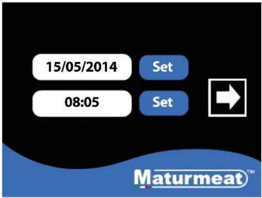
text_image
15/05/2014 Set 08:05 Set Maturmeat™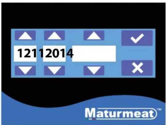
text_image
12112014 Maturmeat™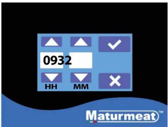
text_image
0932 HH MM Maturmeat™2.2
STARTING THE TEST RECIPE

text_image
15/05/2014 Set 08:05 Set Maturmeat™- After setting date & time, press forward arrow.

text_image
Customer Dealer Producer Maturmeat™- This is the Home page, here you have 3 options to choose from:
i. Customer,
ii. Dealer,
iii. Producer,
Select Customer to proceed.
text_image
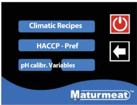
Climatic Recipes HACCP - Pref pH calibr. Variables Maturmeat™- In the customer area, you have 4 options to choose from:
i. Climatic Recipes
ii. HACCP-Performance
iii. pH calbr.
iii. Variables
Select Climatic Recipes.

text_image
My Recipes Default Recipes Create a Recipe Maturmeat™- On the recipes page you can access all recipes; here you have 3 options to choose from:
i. My Recipes
ii. Default Recipes
iii. Create a Recipe
Select My recipes.
text_image
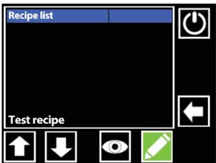
Recipe list Test recipe- The test recipe is found at the bottom of the list; press the downward arrow until you see the recipe.

text_image
Recipe list Ongoing recipe! Start new ? × ✓ Test recipe-
Highlight the test recipe in red, press the start button, a message will appear, press the check mark button to proceed.
-
The test recipe should automatically start. Look at the start/pause button to make sure its green.
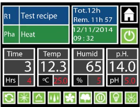
text_image
R1 Test recipe Pha Heat Tot.12h Rem. 11h 57 12/11/2014 09:32 Time Temp Humid p.H. 3 12.3 65 14.0 Hrs 4 °C 25.0 % 5 pH 5.0The following is an explanation of the recipe screen to help you understand the parameters you will be interacting with daily on the Maturmeat ^® controller. Alternatively, use the link to see the video online https://www.youtube.com/watch?v=AfhtshDWTdl
other
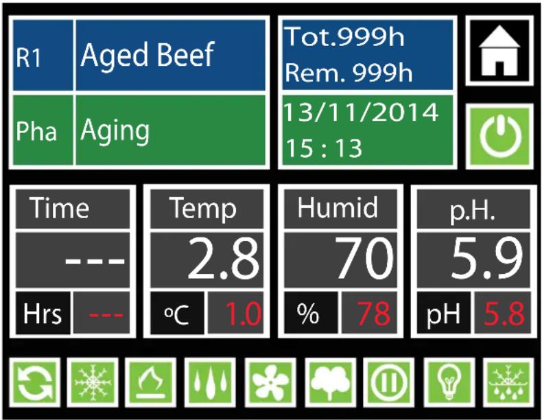
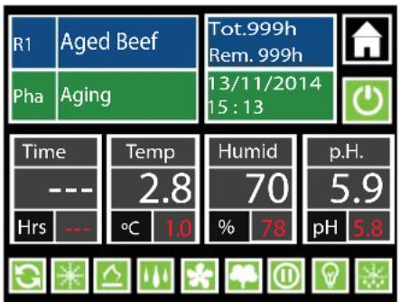
| Metric | Value | | :--- | :--- | | R1 | Aged Beef | | Pha | Aging | | Tot.999h Rem. 999h | | | 13/11/2014 15:13 | | | Time | --- | | --- | --- | | Temp | 2.8 | | °C | 1.0 | | Humid | 70 | | % | 78 | | pH | 5.9 | | p.H. | 5.8 || R1 | Beef | Recipe name currently in use Recipe phase currently preforming | Home icon: has 2 functions, exit recipe (when recipe is paused), check VTE/VTC values (while recipe is running) | |
| PHA | Aging | |||
| Tot.10h Rem. 9h 57 | Total time of the current recipe in use Remaining time of the recipe in use | Start/Pause Recipe: Icon Green = recipe is working Icon Black = recipe is paused | ||
| Time Hrs | --- | Time remaining in current phase WHITE VALUE: displays time remaining in current phase. RED VALUE: displays total time in current phase | Temp 12.3 °C | Temp for current phase WHITE VALUE: displays current temp inside unit. RED VALUE: displays temp set point needed to be reached. |
| Note: set value to 0 to skip phase when necessary | Note: There is +/- 2 range. Temp must be achieved before any other functions will work. It is normal to see humidity go out of range during cooling/heating | |||
| Humid 75 % | 50 | Relative Humidity for current phase WHITE VALUE: displays current humidity inside unit. RED VALUE: displays humidity set point needed to be reached. | p.H. 5.2 pH | pH for current phase (guide only) *WHITE VALUE: displays current pH value inside unit. RED VALUE: displays ideal value to be reached. |
| Note: There is +/- 7 range. Temp must be achieved before any other functions will work. It is normal to see humidity go out of range during cooling/heating | *This value can only be read when pH probe has been purchased and connected. | |||
NOTE
Red value can be changed for the duration of the phase only, default values will reset once recipe advances into the next phase,
 | Air Cycling:If the icon is green and the frame flashing, this indicates that the air inside the unit is being equalized to reduce cool/warm spots. All functions will be disabled for a set period of time. It is normal for the temp and humidity to go out of range during this time. The same key gives you the possibility of disabling or forcing an air cycle. |
 | Cooling:If the icon is green and the frame flashing, this indicates that cooling system is working to bring the temp down to the set point. The same key gives you the possibility of disabling or forcing the action. |
 | Heating:If the icon is green and the frame flashing, this indicates that the heating system is working to bring the temp up to the set point. The same key gives you the possibility of disabling or forcing the action. |
 | Humidification:If the icon is green and the frame flashing, this indicates that humidification system is working to bring the RH up to the set point. The same key gives you the possibility of disabling humidification. Note when the unit needs to dehumidify, the humidification icon will change to the dehumidification icon. |
 | Dehumidification:If the icon is green and the frame flashing, this indicates that dehumidification system is working to bring the RH down to the set point. The same key gives you the possibility of disabling dehumidification. Note when the unit needs to humidify, the dehumidification icon will change to the humidification icon. |
 | Fan low/high speed:If this icon is green with the green frame flashing, this indicates that the fan is working at a low speed; if the icon is blue with blue flashing frame, this indicates that the fan is working at a high speed. Note you can toggle between high and low speed setting simply by pressing the fan icon. |
 | |
 | Aroma:If the icon is green and the frame flashing, this indicates that liquid is drawn out of the aroma tank by the Fumotic®, nubulized and sprayed into the unit. The same key gives you the possibility of disabling or forcing the action. |
 | Rest/Recovery:If the icon is green and the frame flashing, this indicates that the MaturmeatTM has disabled all functions for a set period of time to allow the product inside to rest. It is normal for the temp and humidity to go out of range during this time. The same key gives you the possibility of disabling or forcing the action. |
 | Internal Light:If the icon is green and the frame flashing green, this indicates the light inside the unit is switched on. |
 | Defrost:If the icon is green and the frame flashing, this indicates that the evaporator probe has detected a temp (set in the system variables) and has triggered a defrost. All functions will be disabled during the defrost period. It is normal for the temp and humidity to go out of range during this time. The same key gives you the possibility of disabling or forcing the action. |
2.4
STARTING A DEFAULT CLIMATIC RECIPE
Follow the steps below to start a default climatic recipe. Alternatively, use the link to see the video online https://www.youtube.com/watch?v=TPEB3mqgs7M

text_image
Customer Dealer Producer Maturmeat™- From the Home page, Select Customer to proceed.

text_image
Climatic Recipes HACCP - Pref pH calibr. Variables Maturmeat™- Select Climatic Recipes.

text_image
My Recipes Default Recipes Create a Recipe Maturmeat™- Select Default Recipes

text_image
Recipe list Aged Beef Aged Deer Aged Game Aged Horse R. Mortis- On this page you will find a list of 5 preset climatic recipes. Press the recipe name or use the down icon until you see the recipe you want to use.

text_image
Recipe list Aged Beef Ongoing recipe! Start new ? Aged De Aged Ga Aged Ho R. Mortis- With your recipe highlighted in red, press the start button, a message will appear, press the check mark button to proceed.
other
| Metric | Value | | :--- | :--- | | R1 | Aged Beef | | Pha | Aging | | Tot.999h Rem. 999h | 13/11/2014 15:13 | | Time | --- | | Temp | 2.8 | | Humid | 70 | | pH | 5.9 | | Hrs | --- | | °C | 1.0 | | % | 78 | | pH | 5.8 |- Your selected recipe should automatically start. Look at the start / pause button to make sure its green.
2.5
MODIFING RECIPE PARAMETERS
Your production should be monitored daily, you may need and probably will have to, modify a recipe at some point, this could be due to several factors (meat type, meat quality, etc.). Follow the steps below to modify Time, Temp and Humidity parameters.
Modifications to default/saved recipes while in course are temporary and will last until the end of the phase, once the phase changes the parameters are returned to their preset value.

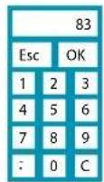
1. To change a set point, press the number in Red.

text_image
R1 Aged B 73 9h Pha Aging Esc OK 2014 Time 1 2 3 d --- 4 5 6 0 p.H. Hrs --- 7 8 9 8 pH 5.8 : 0 C- The keypad will appear, enter your value and press OK to temporarily save.

other
| Metric | Value | | :--- | :--- | | R1 | Aged Beef | | Tot.999h Rem. 999h | | | 3/11/2014 15:13 | | | Time | —— | | Temp | 2.8 | | Humid | 70 | | pH | 5.9 | | Hrs | —— | | °C | 1.0 | | % | 73 | | pH | 5.8 |- The recipe will continue with the new modified value until the end of the phase.

text_image
Customer Dealer Producer Maturmeat™- From the Home page, 2. Select HACCP-Pref. Select Customer to proceed.

text_image
Climatic Recipes HACCP - Pref pH calibr. Variables Maturmeat™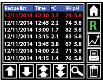
other
| Recipe list | Time | °C | RH pH | |---|---|---|---| | 12/11/2014 | 12:30 | 3.3 | 79 5.8 | | 12/11/2014 | 12:45 | 2.2 | 74 5.8 | | 12/11/2014 | 13:00 | 1.7 | 82 5.8 | | 12/11/2014 | 13:15 | 2.1 | 83 5.8 | | 12/11/2014 | 13:45 | 3.8 | 67 5.8 | | 12/11/2014 | 14:00 | 2.2 | 71 5.8 | | 12/11/2014 | 14:15 | 1.4 | 76 5.8 |- Here you can search, view and print production data.
 | Home Icon:Pressing the home icon exits the HACCP-Performance page and returns you to the home page |
 | R Icon:Displays production data in line form. Press the R and it turns to an H.Note: while in R mode you cannot access the graphs, for this you must be in H mode |
 | H Icon:Displays the same production data (in green font), this data cannot be printed. At this point you can press graph icon to change to graph view. |
 | Print Icon:Line data can be printed via a specialized handheld printer purchased through your StagionelloTM distributor. |
 | Trash Icon:Delete line data. |
 | Search Icon:Line data can accumulate quickly, use the search icon to advance to a specific date. |
 | Page Down Icon:Quickly scroll down page by page. |
 | Page Up Icon:Quickly scroll up page by page. |
 | Down Icon:Scroll down one line at a time. |
 | Up Icon:Scroll up one line at a time. |
2.7
CHECKING HACCP-PERFROMANCE AS A GRAPH
Graph View:
After switching to H mode, you can now access your production data in the form of a graph by pressing the graph icon. Temperature, Humidity and pH can be viewed here. You will notice that the print icon has been replaced by an Eye icon, this will allow you to toggle between 3 graphs.
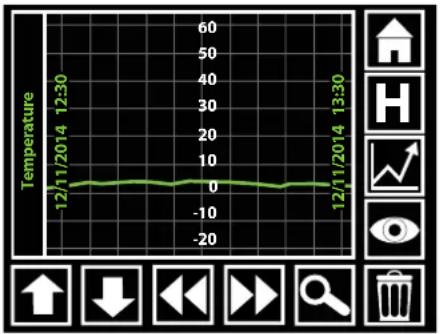
line
| Time | Temperature | | ----------------- | ----------- | | 12/11/2014 12:30 | 0 | | 12/11/2014 13:30 | 0 |Temperature Graph
line
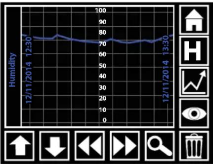
| Date | Humidity | | ---------- | -------- | | 12/11/2014 | 75 | | 13/30 | 75 |Humidity Graph
line
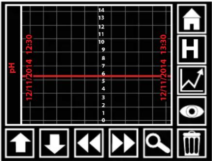
| Time | pH | |---|---| | 12/11/2014 12:30 | 5 | | 12/11/2014 13:30 | 5 |pH Graph

Home Icon:
Pressing the home icon exits the HACCP-Performance page and returns you to the home page

H Icon:
While in graph view, pressing H will exit graph view and return you to R mode (line data).

Eye Icon:
While in graph view, press the eye icon to toggle through the 3 graphs (Temp, Humidity, pH).

Trash Icon:
Delete data.

Search Icon:
Graph data can accumulate quickly, use the search icon to advance to a specific date.

Forward Icon:
Advance forward to the next section data.

Backward Icon:
Move backward to the next section data.

Down Icon:
Has no functionality on graph view.

Up Icon:
Has no functionality on graph view.
2.8
The following is an explanation to help you understand the parameters involved in creating a new recipe on the Climatouch ^® controller. Alternatively, use the link to see the video online
https://www.youtube.com/watch?v=-HKpifRFNWE
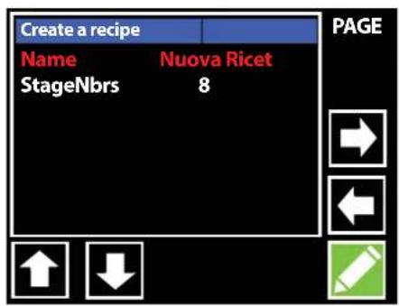
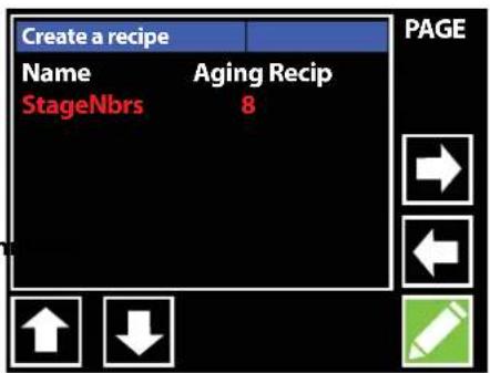
Create Recipe Page 1.
On this page there are 2 sections to fill in:
- Recipe Name
- Number of sequential stages

text_image
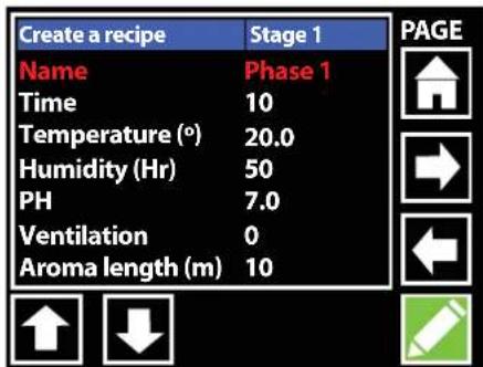
Create a recipe Name Nuova Ricet StageNbrs 8 PAGE ↑ ↓Create Recipe Page 2.
There are 16 recipe variables to create:
-
Name: Phase Name.
-
Time: Number of hours this phase should last.
-
Temp(°C): The average temperature that should be maintained during this phase.
-
Humidity: The average humidity that should be maintained during this phase.
-
Ventilation: Fan speed 0 = low speed, 1 = high speed.
text_image
Create a recipe Stage 1 Name Phase 1 Time 10 Temperature (°) 20.0 Humidity (Hr) 50 PH 7.0 Ventilation 0 Aroma length (m) 10 PAGE-
PH: by setting a value here, you are creating a guideline. Note: in order for the climatouch® to read pH data in your product, the optional pH probe must be connected to the Maturmeat™.
-
Aroma length(m): by setting a value here, the liquid in the aroma tank will be drawn into the Fumotic® and will be nebulized and sprayed into the unit for the length of time (in minutes) set by you.
-
Per.Aroma(h): by setting a value here, you are setting the number of hours between each aroma activation.
-
Recovery length(m): all functionality is shut down to allow the product inside time to rest, this variable represents the amount of time in minutes that the rest/recovery will last.
-
Recovery period(h): this variable sets the number of hours between each rest/recovery period.
-
Recycle length(s): all functionality is shut down and the air inside is cycled in an attempt to equalize the climate, this variable represents the amount of time in seconds that the air cycle will last.
-
Recycle period(m): this variable sets the number of minutes between each air cycling period.
-
Airenew length(m): all functionality is shut down and the air inside is flushed out and fresh air is introduced into the unit, this variable represents the amount of time in minutes that the air exchange will last. Note this works with the Air exchange kit (Standard on MATC150/400/800/300/600kg models only. Optional on MATC60/100/200/100+100kg models)
-
Airenew period(h): this variable sets the number of hours between each air exchange period.
-
Free Variable: this doesn't need to be set, this represents an extra space for future addition of another variable.
-
Overtime(h): this variable extends the phase in case extra time is needed.
2.9
CREATING AND SAVING NEW RECIPES
This guide will help walk you through the process of creating and saving your own recipe. Alternatively, use the link to see the video online https://www.youtube.com/watch?v=FQfpGkWbeNs
The 3 tools you will use to modify the recipe parameters are:

text_image
Esc Nuova Ricetta OK q w e r t y u i o p a s d f g h j k l z x c v b n m < > Del Shift NumKeyboard
Keypad
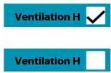
Check box

text_image
Customer Dealer Producer Maturmeat™- From the Home page, Select Customer to proceed.

text_image
Climatic Recipes HACCP - Pref pH calibr. Variables Maturmeat™- Select Climatic Recipes.

text_image
My Recipes Default Recipes Create a Recipe Maturmeat™- Select Create a Recipe
text_image
Create a recipe Name Nuova Ricet StageNbrs 8 PAGE ↑ ↓- With the name field highlighted in red, Press the pencil icon to activate the onscreen keyboard and set your recipe name.

text_image
Create a recipe PAGE Aging Recipe OKEsc q w e r t y u i o p sa fdhgk l z Del><_ ShiftShift Num- Use delete key to empty the field, type the name of your new recipe and press OK.
text_image
Create a recipe Name Aging Recip StageNbrs 8 PAGE ↑ ↓- Use the down arrow to highlight the next field, press the pencil icon to activate the keypad to select the number of stages you want your recipe to have.
CREATING AND SAVING NEW RECIPES continued

text_image
Create a recipe Name StageNbrs 1 esc OK 1 2 3 4 5 6 7 8 9 . 0 C PAGE Create a recipe Stage 1 Name Phase 1 Time 10 Temperature (°) 20.0 Humidity (Hr) 50 PH 7.0 Ventilation 0 Aroma length (m) 10 PAGE Create a recipe Dry Age OKEsc q w e r t y u i o p sa fghgk l z Del>text_image
Create a recipe Stage 1 PAGE Name Dry Age Time 10 Temperature (°) 20.0 Humidity (Hr) 50 PH 7.0 Ventilation 0 Aroma length (m) 10 Create a recipe Stage 1 PAGE Name Dry Age Time 999 Temperature (°) 1.5 Humidity (Hr) 50 PH 7.0 Ventilation 0 Aroma length (m) 10 Create a recipe 75 Page Name Time Esc OK Temperature Humidity (Hr) PH 4 5 6 Ventilation Aroma length 7 8 9 . 0 CCREATING AND SAVING NEW RECIPES continued
text_image
Create a recipe Stage 1 Name Dry Age Time 999 Temperature (°) 1.5 Humidity (Hr) 75 PH 5.9 Ventilation 0 Aroma length (m) 10 PAGEtext_image
Create a recipe Stage 1 Name Dry Age Time 10 Ventilation H Temperatu Humidity (Hr) 75 PH 5.9 Ventilation 0 Aroma length (m) 10 PAGE ↑ ↓text_image
Create a recipe Stage 1 Per.Aroma(h) 0 Recov.length(m) 30 Recov.period(h) 2 Recycl.length(s) 300 Recycl.period(m) 120 Airenew.length(m) 5 Airenew.period(h) 12 PAGE ↑ ↓text_image
Create a recipe Stage 1 Recov.period(h) 2 Recycl.length(s) 300 Recycl.period(m) 120 Airnew.length(m) 5 Airnew.period(h) 12 Free variable 0 Overtime(h) 0text_image
Save recipe Position 1 2 3 4 5 6 7 PAGEtext_image
Save recipe Position 1 Please wait Save in progress 7NOTE
The Airenew parameter is connected directly to the Air Exchange kit. This kit only comes standard on the MATC150/400/800/300/600kg models. On all other models the air exchange kit is optional.NOTE
The Aroma parameters are connected directly to the Fumotic® and the aroma tank, if you do not use liquid flavoring (ie. Natural liquid smoke) in your recipe set the values to 0 to avoid false alarms.2.10
STARTING A SAVED RECIPE
Follow the steps below to start a recipe that you have previously created and saved. text_image
Customer Dealer Producer Maturmeat™text_image
Climatic Recipes HACCP - Pref pH calibr. Variables Maturmeat™text_image
My Recipes Default Recipes Create a Recipe Maturmeat™text_image
Recipe List Aging Recipetext_image
Recipe list Aging Recipe Ongoing recipe! Start new ? ✗ ✓text_image
R1 Aging Recipe Tot.999h Rem. 999h 21/12/2014 08:57 Pha Dry Age Time --- Temp 3.6 Humid 72 p.H. Hrs --- °C 1.5 % 75 pH 5.92.11
FORCING AROMA
Follow the steps below to force aroma anytime during a default climatic recipe or a recipe that you have previously created and saved. natural_image
Simple white cloverleaf icon on a green background (no text or symbols)text_image
R1 Aged Beef Tot.999h Rem. 999h 13/11/2014 15:13 Pha Aging Time Temp Humid p.H. --- 2.8 70 5.9 Hrs --- °C 1.0 % 78 pH 5.8 Force Aroma Time 00 20 --- HH MM ✗ 5.9 Hrs --- °C 1.0 % 78 pH 5.83.1
CALIBRATING STANDARD PROBES
Your Maturmeat™ has 3 standard probes that can be calibrated by you or by a technician. The probes are checked thoroughly before your Maturmeat™ leaves the factory. A certified instrument to measure either humidity and/or temperature must be used to calibrate the probes on your Maturmeat™. Follow the steps below to access the variables page to begin calibrating the probes, alternatively, use the link to see the video online https://www.youtube.com/watch?v=TmPLBJ2aC4Q text_image
Customer Dealer Producer Maturmeat™text_image
Climatic Recipes HACCP - Pref pH calibr. Variables Maturmeat™text_image
Var. Meaning CSA CORR.SONDA AMB 0.0 °C CSU CORR.SONDA U. 0 Hg CSC CORR.SONDA C.D 0.0 °Ctext_image
Var. Meanin CSA CORR CSU CORR CSC CORR -2 Esc OK 1 2 3 4 5 6 7 8 9 : 0 Ctext_image
Climatic Recipes HACCP - Pref pH calibr. Variables Maturmeat™text_image
NOTE Comparison readings should be taken with the fan running and with the fan on pause. Take readings over a period of 5-10min.NOTE
If you do not have a certified or professionally calibrated probe, please consult with a professional for assistance.3.2
CALIBRATING pH PROBE
Your Maturmeat™ has an optional pH probe that can be purchased. The probe is checked thoroughly before your Maturmeat™ leaves the factory. A calibration system has been programmed into Climatouch® allowing you the possibility to calibrate your pH probe anytime. Follow the steps below to successfully calibrate your probe, alternatively, use the link to see the video online https://www.youtube.com/watch?v=AkLgjoDq-G0 Here is what you will need to calibrate the pH probe 1. pH probe 2. Buffer solution 4.01 3. Buffer solution 7.01 4. Water (small amount) 5. Container x 3 (ie.cups) 6. Paper towel/Napkins 7. Marker to label cups  text_image
Buffer Solution pH 4.01text_image
pH 4 pH 7 watext_image
Buffer Solution ater pH 7.01NOTE
Rinse probe with water between each recording of buffer solutions. Use paper towel/napkins with extreme care when drying probe, as probe's surface can easily scratch and become damaged producing false readings. text_image
Customer Dealer Producer Maturmeat™text_image
Climatic Recipes HACCP - Pref pH calibr. Variables Maturmeat™text_image
1438 pH 4 --- pH 7 Maturmeat™text_image
pH 4text_image
Waterbar
| Value | pH 4 | pH 7 | |---|---|---| | 1437 | | | | 2063 | | |text_image
pH 7text_image
Watertext_image
1437 pH 4 2063 pH 7 Maturmeat™NOTE
Calibration of the optional pH probe is highly recommended each time a new production lot is started to ensure accuracy. If the probe has been sitting in its protective housing unused for 3 weeks or longer, it is highly recommended to calibrate the pH probe.3.3
FUMOTIC® DESCRIPTION AND SUPPLY TANKS
The Fumotic® is our patented system that enables you to introduce humidity when necessary. The water is drawn out of a tank situated on top of your Maturmeat™ and fed directly into the Fumotic®. The tank needs to be filled periodically, and should be checked daily, specifically before the end of the business day, or at any time when you will be away from the Maturmeat™ for an extended period of time. Doing this will help avoid triggering H 20/Flavour level alarms. The aroma tank works on the same principal but uses a flavoring liquid instead of water to introduce into your recipe, this can be added manually during a default climatic recipe or preprogrammed into a custom made recipe. DANGER
System Damage Use zero solid residue liquids only, do not use corrosive or explosive liquids; do not use liquids that increase in volume when heated. Failure to do so can cause damage to the unit and /or the user.Liquid Level Sensor:
Introduced in late 2013 is the electronic leveling system, this innovation allows for simpler connection to the Fumotic® and a higher degree of accuracy when reading water levels. text_image
Water Filter Level Arm with electric sensor Connection to PLC Water Line Fumotic®3.4
WATER FILTER
This chart shows the maximum duration of the filter's life based on the Hardness of water passing through it.| °fH | ppm, mg/L | dGH, °dH | gpg | °e, °Clark | Max.Duration |
| 9 | 0.9 | 16.07 | 15.41 | 12.83 | 220L |
| 18 | 1.8 | 32.13 | 30.82 | 25.65 | 110L |
| 27 | 2.7 | 48.20 | 46.22 | 38.48 | 80L |
| 36 | 3.6 | 64.26 | 61.63 | 51.30 | 60L |
| 45 | 4.5 | 80.33 | 77.04 | 64.13 | 50L |
natural_image
3D illustration of a cylindrical mechanical component with a central shaft (no text or symbols)Water Filter:
The contents of the filter and bacteriostatic housing itself meets the most stringent quality standards certified by the FOOD AND DRUG ADMINISTRATION (title 21, section 173.25, paragraph A, sub-paragraph 1). The filter's nylon fabric with a filtration level of 150 microns complies with directive EEC 128/1990 and certified to FDA standards (title 21, paragraph 177). The homopolymer polypropylene structure is also FDA certified.NOTE
The water used in conjunction with the Fumotic ^® should have a low mineral content to prevent calcium build up inside the Fumotic ^® . Calcium buildup inside the Fumotic ^® can create many problems, please contact a local Maturmeat ^™ service point for assistance.3.5
FUMOTIC® REAR VEIW
text_image
Vapor out Drain out Aroma in Water innatural_image
3D rendering of a mechanical component with hexagonal base and central hole (no text or symbols)Reducer:
This adapter is connected on your Fumotic® to allow for the waterline from the Water tank to be connected. Vapor out: connects inside the unit to add humidity or aroma/flavor Drain out: expels any overflow from Fumotic® Aroma In: connects directly to aroma/flavor tank Water In: connects directly to water tank, dual purpose connection can be connected to direct waterline Screen: prevents large particles from entering the fumotic, this is not a substitute for a filter.Direct Connect:
The waterline connected to the Fumotic ^® is dual purpose. From the factory, the water tank is connected, but this can be removed and connected directly to a dedicated waterline. See page 23 for instructions.3.6
FUMOTIC® FRONT VEIW
Level probe sensitivity adjustment: This should not be touched Level probe inverter: This should not be touched Breaker switch: A safety measure to prevent overloading of the circuit, can also be used to manually shut off the Fumotic® Vapor discharge: manual discharge of vapor 12 Point connection: (12 pin twin model, 9 pin all other models) 4 point connection: Connector for tank level system natural_image
Diagram of a server rack with indicator lights and ports (no text or labels)3.7
HOW TO CONNECT DIRECT WATERLINE TO FUMOTIC®
natural_image
Diagram of a hand inserting a cable into a wall-mounted device (no text or symbols)natural_image
Mechanical assembly diagram showing a rotating component with red arrows indicating motion (no text or symbols)natural_image
Technical diagram showing a mechanical assembly with a spring-like component and a curved housing (no text or symbols)text_image
WATER Connection Pointnatural_image
Illustration of a mechanical component with threaded pins and a handle (no text or symbols)! DANGER
Electrical Shock Hazard Unplug/Disconnect power before touching wiring of any kind. Failure to do so can result electric shock or death. 6. Place wiring neatly back in wiring duct 7. Turn on water supply, and check for leaks. 8. Turn power back on to unit.3.8
SCALE FORMATION INSIDE FUMOTIC®
Scale build up is caused by the high mineral content in your water also know as "Hard water". Scale build up inside the Fumotic® will reduce performance and cause severe damage. Should scale build up inside your Fumotic® contact your local Maturmeat™ service point for assistance, the process to remove scale from the system requires removal of the Fumotic® and the use of solutions to dissolve the scale and fluids to clean and purify the system rendering it safe for use with food. Be advised that the manufacturers warranty is voided when scale/calcium is found anywhere in the humidification system from the tanks leading into the Fumotic® to inside of the Maturmeat™ itself. DANGER
Shock Hazzard Before attempting to clean any part the unit, unplug the unit's power or shut down power to the unit if connected directly to an electrical panel, failure to do so can result in serious injury of death.Cleaning Maintenance:
Cleaning your Maturmeat™ should be done as often as needed. AISI 304 stainless steel has a layer of oxide preventing rust. Using abrasive and/or corrosive detergents can deteriorate this layer. Internal and external stainless steel surfaces must be washed with water and mild neutral soap. In case of bad odors, use a vinegar and water solution to clean the entire surface. Rinse thoroughly then dry the surface with care.Rounded Corners:
All vertical corners are rounded to provide simple and easy clean up. The rounded corners also prevent the build up of fine particles that may otherwise become trapped. natural_image
Illustration of a kitchen waste bin with soap bottle and bucket nearby, showing exterior and interior views (no text or symbols)Condensing Unit:
All condensing units require regular maintenance. The purpose of the condenser is to release absorbed heat; If the condenser coils are clogged with dirt or the fins are bent it restricts or block air flow through the coils and interferes with the heat exchange. This causes the system to work harder and shortens the life of your compressor. Please check your condensing unit regularly. Please unplug the unit's power or shut down power to the unit if connected directly to an electrical panel before attempting to clean. You can use compressed air to clear away and loose dirt or dust that may impair normal use. natural_image
Illustration of a kitchen appliance with a cylindrical lid and rectangular base (no text or symbols)DANGER
Shock Hazzard Before attempting to change the light bulb, unplug the unit's power or shut down power to the unit if connected directly to an electrical panel, failure to do so can result in serious injury of death.Light Bulb Replacement:
Inside your Maturmeat™ you will find a Light bulb set in a protective glass enclosure. In order to change the bulb, unscrew the 4 screws on the mounting plate holding the protective glass cover. Once removed, carefully set aside mounting plate and glass cover, remove the halogen bulb. When installing the new bulb, be sure not to touch the glass with your fingers leaving behind oils that will burn out the new bulb. natural_image
Diagram of a mechanical component with a spring-like feature and downward arrows indicating force or movement (no text or symbols)3.11
EMPTYING THE DRAIN TRAY
DANGER
Slip Hazzard Overflow from the drain tray as a result of neglecting to empty it can result in serious injury or death. Your Maturmeat™ has a tray, which collects excess water moisture. The tray should be emptied daily to avoid overflowing onto your floor creating the possibility of unsafe or unsanitary conditions in your workplace. natural_image
Illustration of a server rack with a blue mesh cover and a white panel, no text or symbols present.3.12
TEMPERATURE MAINTENANCE
You can cross reference the follow variable codes with the list found on pages 36 - 41 Heating and cooling is managed in the neutral zone on the basis of the temperature set point and the temperature differentials (parameters DTNC and DTNF). Cooling is activated when the set point + (DTF value) is exceeded and remains enabled until the set point is reached (with DTNF = 0). Heating is activated when the temperature goes below the set point -(DTNC value) and remains enabled until the set point is reached (with DTNC = 0). It is possible to set a “dead zone” with the parameters (DTNC) and (DTNF) which de-activates heating and cooling when the temperature is between the set point -(DTNC) and the set point +(DTNF). line
| Time(s) | Temperature (°C) | Event Type | |---------|------------------|--------------------------------| | 0 | ~0 | Dehumidification Activated | | 1 | ~0 | Dehumidification Activated | | 2 | ~0 | Humidification Activated | | 3 | ~0 | Humidification Activated | | 4 | ~0 | Dehumidification Activated | | 5 | ~0 | Dehumidification Activated | | 6 | ~0 | Dehumidification Activated | | 7 | ~0 | Dehumidification Activated | | 8 | ~0 | Dehumidification Activated | | 9 | ~0 | Dehumidification Activated | | 10 | ~0 | Dehumidification Activated | | 11 | ~0 | Dehumidification Activated | | 12 | ~0 | Dehumidification Activated | | 13 | ~0 | Dehumidification Activated | | 14 | ~0 | Dehumidification Activated | | 15 | ~0 | Dehumidification Activated | | 16 | ~0 | Dehumidification Activated | | 17 | ~0 | Dehumidification Activated | | 18 | ~0 | Dehumidification Activated | | 19 | ~0 | Dehumidification Activated | | 20 | ~0 | Dehumidification Activated | | 21 | ~0 | Dehumidification Activated | | 22 | ~0 | Dehumidification Activated | | 23 | ~0 | Dehumidification Activated | | 24 | ~0 | Dehumidification Activated | | 25 | ~0 | Dehumidification Activated | | 26 | ~0 | Dehumidification Activated | | 27 | ~0 | Dehumidification Activated | | 28 | ~0 | Dehumidification Activated | | 29 | ~0 | Dehumidification Activated | | 30 | ~0 | Dehumidification Activated | | 31 | ~0 | Dehumidification Activated | | 32 | ~0 | Dehumidification Activated | | 33 | ~0 | Dehumidification Activated | | 34 | ~0 | Dehumidification Activated | | 35 | ~0 | Dehumidification Activated | | 36 | ~0 | Dehumidification Activated | | 37 | ~0 | Dehumidification Activated | | 38 | ~0 | Dehumidification Activated | | 39 | ~0 | Dehumidification Activated | | 40 | ~0 | Dehumidification Activated | | 41 | ~0 | Dehumidification Activated | | 42 | ~0 | Dehumidification Activated | | 43 | ~0 | Dehumidification Activated | | 44 | ~0 | Dehumidification Activated | | 45 | ~0 | Dehumidification Activated | | 46 | ~0 | Dehumidification Activated | | 47 | ~0 | Dehumidification Activated | | 48 | ~0 | Dehumidification Activated | | 49 | ~0 | Dehumidification Activated | | 50 | ~0 | Dehumidification Activated | | 51 | ~0 | Dehumidification Activated | | 52 | ~0 | Dehumidification Activated | | 53 | ~0 | Dehumidification Activated | | 54 | ~0 | Dehumidification Activated | | 55 | ~0 | Dehumidification Activated | | 56 | ~0 | Dehumidification Activated | | 57 | ~0 | Dehumidification Activated | | 58 | ~0 | Dehumidification Activated | | 59 | ~0 | Dehumidification Activated | | 60 | ~0 | Dehumidification Activated | | 61 | ~0 | Dehumidification Activated | | 62 | ~0 | Dehumidification Activated | | 63 | ~0 | Dehumidification Activated | | 64 | ~0 | Dehumidification Activated | | 65 | ~0 | Dehumidification Activated | | 66 | ~0 | Dehumidification Activated | | 67 | ~0 | Dehumidification Activated | | 68 | ~0 | Dehumidification Activated | | 69 | ~0 | Dehumidification Activated | | 70 | ~0 | Dehumidification Activated | | 71 | ~0 | Dehumidification Activated | | 72 | ~0 | Dehumidification Activated | | 73 | ~0 | Dehumidification Activated | | 74 | ~0 | Dehumidification Activated | | 75 | ~0 | Dehumidification Activated | | 76 | ~0 | Dehumidification Activated | | 77 | ~0 | Dehumidification Activated | | 78 | ~0 | Dehumidification Activated | | 79 | ~0 | Dehumidification Activated | | 80 | ~0 | Dehumidification Activated | | 81 | ~0 | Dehumidification Activated | | 82 | ~0 | Dehumidification Activated | | 83 | ~0 | Dehumidification Activated | | 84 | ~0 | Dehumidification Activated | | 85 | ~0 | Dehumidification Activated | | 86 | ~0 | Dehumidification Activated | | 87 | ~0 | Dehumidification Activated | | 88 | ~0 | Dehumidification Activated | | 89 | ~0 | Dehumidification Activated | | 90 | ~0 | Dehumidification Activated | | 91 | ~0 | Dehumidification Activated | | 92 | ~0 | Dehumidification Activated | | 93 | ~0 | Dehumidification Activated | | 94 | ~0 | Dehumidification Activated | | 95 | ~0 | Dehumidification Activated | | 96 | ~0 | Dehumidification Activated | | 97 | ~0 | Dehumidification Activated | | 98 | ~0 | Dehumidification Activated | | 99 | ~0 | Dehumidification Activated | | 100 | ~0 | Dehumidification Activated | | - | - | Cold Off | | - | - | Cold On | | - | - | Heat On | | - | - | Heat Off | | - | - | Heat On | | - | - | Neutral Zone | | - | - | Heat Off | | - | - | Heat On | | - | - | Heat Off | | - | - | Heat On | | - | - | Heat Off | | - | - | Heat On | | - | - | Heat Off | | - | - | Heat On | | - | - | Heat Off | | - | - | Heat On | | - | - | Heat Off | [Time(s)]3.13
HUMIDITY MAINTENANCE
You can cross reference the follow variable codes with the list found on pages 36 - 41 Humidification and dehumidification is managed in the neutral zone on the basis of the humidity set point and the humidity differentials (parameters DUU and DUD). Dehumidification is activated when the set point + (DUD value) is exceeded and remains enabled until the set point is reached (with DUNS = 0). Humidification is activated when the humidity value falls below the set point -(DUU value) and remains enabled until the set point is reached (with DUNI = 0). It is possible to set a “dead zone” with parameters (DUNS) and (DUNI) which deactivates humidification and dehumidification when the humidity is between the set point -(DUNI) and the set point + (DUNS). Humidification and dehumidification management can be excluded with the variables (U) and (DE). With the (HR) variable you can decide whether to show the humidity value on the display or not. There are three dehumidification modes found in parameter (DEU): 0. Dehumidify with cooling (cooling is activated to dehumidify, heating is activated only to maintain the ambient temperature; 1. Dehumidify with heating (heating is activated to dehumidify, cooling is activated only to maintain the ambient temperature; 2. Separate dehumidification (the dehumidification system is activated without the use of heating and cooling, they will only be activated in the event of thermoregulation). It is possible to set a limit on the dehumidification phase with parameter (LDE) by flagging an alarm. It is possible to set a limit on the humidification phase with parameter (LUM) by flagging an alarm. line
| Time(s) | RH% | | ------- | --- | | 0 | 0 | | 1 | 1 | | 2 | 0 | | 3 | 1 | | 4 | 0 | | 5 | 1 | | 6 | 0 | | 7 | 1 | | 8 | 0 | | 9 | 1 | | 10 | 0 | | 11 | 1 | | 12 | 0 | | 13 | 1 | | 14 | 0 | | 15 | 1 | | 16 | 0 | | 17 | 1 | | 18 | 0 | | 19 | 1 | | 20 | 0 | | 21 | 1 | | 22 | 0 | | 23 | 1 | | 24 | 0 | | 25 | 1 | | 26 | 0 | | 27 | 1 | | 28 | 0 | | 29 | 1 | | 30 | 0 | | 31 | 1 | | 32 | 0 | | 33 | 1 | | 34 | 0 | | 35 | 1 | | 36 | 0 | | 37 | 1 | | 38 | 0 | | 39 | 1 | | 40 | 0 | | 41 | 1 | | 42 | 0 | | 43 | 1 | | 44 | 0 | | 45 | 1 | | 46 | 0 | | 47 | 1 | | 48 | 0 | | 49 | 1 | | 50 | 0 | | 51 | 1 | | 52 | 0 | | 53 | 1 | | 54 | 0 | | 55 | 1 | | 56 | 0 | | 57 | 1 | | 58 | 0 | | 59 | 1 | | 60 | 0 | | 61 | 1 | | 62 | 0 | | 63 | 1 | | 64 | 0 | | 65 | 1 | | 66 | 0 | | 67 | 1 | | 68 | 0 | | 69 | 1 | | 70 | 0 | | 71 | 1 | | 72 | 0 | | 73 | 1 | | 74 | 0 | | 75 | 1 | | 76 | 0 | | 77 | 1 | | 78 | 0 | | 79 | 1 | | 80 | 0 | | 81 | 1 | | 82 | 0 | | 83 | 1 | | 84 | 0 | | 85 | 1 | | 86 | 0 | | 87 | 1 | | 88 | 0 | | 89 | 1 | | 90 | 0 | | 91 | 1 | | 92 | 0 | | 93 | 1 | | 94 | 0 | | 95 | 1 | | 96 | 0 | | 97 | 1 | | 98 | 0 | | 99 | 1 | | | |3.14
FIRMWARE UPDATE CLIMATOUCH®
Please follow these directions closely, failure to do can result in complete failure of the device your trying to update, be sure to connect and disconnect cables when power is OFF, or unless otherwise directed. What you will need before starting. • Copy of the latest firmware • Hyperterminal software - RS232 Cable • RS232 to USB Cable - 7mm wrench natural_image
Close-up of a circular object with a white border, possibly a CD or DVD (no visible text or symbols)natural_image
Coiled white cable with a small plug, wrapped in plastic wrap (no visible text or symbols)natural_image
Close-up of a white cable with two black connectors, lying on a plain surface (no text or symbols visible)natural_image
Close-up of a metallic mechanical component with a circular end and flange (no visible text or symbols)Step 1.
- With a computer connected to the internet, connect the RS232 to USB Cable to install drivers. - Open Hyperterminal.exe program or download form internet and install on your computer. text_image
RS232 to USB Cablenatural_image
Close-up of a computer monitor connected to a USB cable with a red circle highlighting the connector (no visible text or symbols)Step 2.
- Before continuing stop any running program on Maturmeat® and unplug the power cord. - Use 7mm wrench to remove cover on the back of the display controller. natural_image
Close-up of a hand using tweezers to insert or install electronic components on a metal surface (no visible text or symbols)natural_image
Close-up of a hand holding a metallic battery cover with green casing (no visible text or symbols)Step 3.
\- With NO power to Maturmeat® connect the RS232 cable to the display controller text_image
RS232 Connectnatural_image
Close-up of a green circuit board connected to a white RJ4 connector with wires (no visible text or symbols)Step 5.
- Start Hyperterminal and begin to configure the connection. • Page 1 enter name (ie. 2.13). • Page 2 select the com port on your computer where your cable is connected. •Page 3 Bit per second: 57.600 Bit Data: 8 bit Parità/(parity): Nessuno (none) Bit di Stop: 1 Controllo Flusso: Nessuno (none) text_image
ConnectTime Configuration New Connection Enter a name and choose an icon to the connection. Name: Icon OK Canceltext_image
Connect To Load For the following functions: Connect to: Load (100) Connect to: Load (100) Connect to: Load (100) Connect to: Load (100) Connect to: Load (100) Connect to: Load (100) Connect to: Load (100) Connect to: Load (100) Connect to: Load (100) Connect to: Load (100) Connect to: Load (100) Connect to: Load (100) OK Canceltext_image
Properties - COME Importative Defaults File path: comms File size: 5 Format: Preference File size: 5 Controller-Default: Preference Importing OK Cancel ApplyStep 6.
- On the back of the Display put Dip Switch number 8 on ON/UP position, to allow Port Connection (Leaving all the other switches OFF/DOWN). - Plug in Maturmeat®'s power cord the display controller's screen will be white. text_image
Dip Switchesnatural_image
Close-up of a green printed circuit board with a finger pointing to a small electronic component (no visible text or symbols)Step 7.
- From the PC's keyboard press "1" DOWNLOAD IMAGE TO THE.... A string of letters will come up on screen. - From the top of the window select trasferimento (Transfer) then Invia file (send file). - press SFOGLIA/browse and select file to be uploaded (ie. 2.13.bin) - Select Ymodem for the Protocol then Invia (send). text_image
Enrolle The New Program ISO Copyright 2013 Epoxide Iraq In-Replication Programming Application (Version 1.8.83) Main Name: Download Image to the STIRRe Internet Flash ———— 1 Enrolle The New Program ———— 2text_image
Invia file Cartella: C:\Documents and Settings\Ultente Name file: Sloglia Protocolu: Y modem Invia Chudi AnnulieNOTE
- A loading screen will appear, when the counter reaches 11 seconds the download will begin and usually takes about 2 minutes to complete. - With Windows 7 & 8 the main window on hyperterminal may remain white in this case press the "1" key twice so you can proceed.Step 8.
- Once successful, go to the back of the Display, set the Dip Switch number 8 to the OFF/DOWN position. - Unplug the power cord. - Disconnect the RS323 Cable from the display controller. natural_image
Close-up of a green printed circuit board with a finger pointing to a small black LED component (no visible text or symbols)natural_image
Close-up of a green circuit board connected to a white VGA socket and wiring (no visible text or symbols)Step 9.
- Put cover back on and fasten with nuts. - Plug in Maturmeat®'s power cord. - On the display controller go to Producer enter the password 4825 and select Variables to verify all the values are correct and save. - Finally you can go back into the recipe and continue production. natural_image
Close-up of a hand pressing down on a metallic electronic device (no visible text or symbols)natural_image
Close-up of a hand using a tool to cut or mark a metallic component, with no visible text or symbols.3.15
FIRMWARE UPDATE PLC'S
Please follow these directions closely, failure to do can result in complete failure of the device your trying to update, be sure to connect and disconnect cables when power is OFF, or unless otherwise directed. What you will need before starting. • Copy of the latest firmware - Flashloader demonstrator software - USB to TTL Cable • Philips head screwdriver natural_image
Open black electronic device with a circular display and indicator lights (no visible text or symbols)natural_image
Coiled white cable with black connectors, placed on a red plastic bag (no visible text or symbols)natural_image
Close-up of a screwdriver with a black head and metallic shaft (no text or symbols visible)Step 1.
- With a computer connected to the internet, connect the TTL Cable to install drivers. - Open Flashloader.exe program or download form internet and install on your computer. natural_image
Close-up of a black remote control device with a white cable on a wooden surface (no visible text or symbols)Step 2.
- Before continuing stop any running program on Maturmeat® and unplug the power cord. - Use Philips head screwdriver to remove cover on the PLC. - With NO power to Maturmeat® connect the TTL cable to the PLC. natural_image
Close-up of a hand using a power tool to cut electronic components on a circuit board (no visible text or symbols)natural_image
Close-up of hands connecting a green circuit board with black cables (no visible text or symbols)Step 3.
- On the back of the PLC card you will find a small black connector (jumper), Normally the jumper covers 1 pin only. - Make sure to cover both pins with the jumper in order to enable connection mode. - After all connections are made Plug in Maturmeat®'s power cord. text_image
Reset Button Normal Operationtext_image
Communication ModeStep 4.
- Start Flashloader and begin to configure the connection. • Page 1 Select Com Port Baud Rate: 115.200 Time Out (S): 5 Parity: Even Echo: Disabled • Page 2 The PLC will be read quickly if successful the Target Readable message will appear in the window, if not press the reset button on the PLC just above the jumper. text_image
Unit Loader Connection Select the communication port and set settings, then click each to group connection. Connect for 47 networks Port Name: COM1 Supply Type: 115206 User Size: 8 Part: Even Enter Class: Class1 Access: 5text_image
Target to readable Please call Text in process Removed ProtectionStep 5.
• Page 3 From the target drop down box be sure to select 64K. text_image
File Edit Connection TIPS SMT2 Connectivity-line 601 SMT2 Connectivity-line 139k SMT2 Connectivity-line_200k View: Back-uping Name Start author End author Size Fench 0x000000 0x000000 0x000000 0x000000 5.5 Fench 0x000000 0x000000 0x000000 5.5 Fench 0x000000 0x000000 0x000000 5.5 Fench 0x000000 0x000000 0x000000 5.5 Fench 0x000000 0x000000 0x000000 5.5 Fench 0x000000 0x000001 5x888888 5.5 Fench 0x888888 5x888888 5x888888 5.5 Fench 5x888888 5x888888 5x888888 5.5 Fench 5x888888 5x888888 5x888888 5.5 Fench 5x888888 5x888888 5x888888 5.5 Funch 5x888888 5x888888 5x888888 5.5 Funch 5x888888 5x888888 5x888888 5.5 Funch 5x888888 5x888887 5x644444 5.5 Funch 5x644444 5x644444 5x644444 5.5 Legend: 1 x 1 x 1 x 1 x 1 x 1 x 1 x 1 x 1 x 1 x 1 x 1 x 1 x 1 x 1 x 1 x 1 x 1 x 1 x 1 x 1 x 1 x 1 x 1 x 1 x 1 x 1 x 1 x 1 x 1 x 1 x 1 x 1 x 1 xtext_image
Target: STARS-Graindorfer Inc. Ltd. Version: Flash export Name Out Version Cancelature Cash 1.SZ0023 5x 4000 5x +3PF +4/30(9) 2.SZ0023 5x 4000 5x +7PF +4/30(9) 3.SZ0023 5x 4000 5x +8PF +6/30(9) 4.SZ0023 5x 9000 5x +3PF +4/30(9) 5.SZ0023 5x 9000 5x +8PF +4/30(9) 6.SZ0023 5x 9000 5x +9PF +4/30(9) 7.SZ0023 5x 9000 5x +1PF +4/30(9) 8.SZ0023 5x 9000 5x +9PF +4/30(9) 9.SZ0023 5x 9000 5x +9PF +4/30(9) 10.SZ0023 5x 9000 5x +1PF +4/30(9) End Cash Cancel CloseStep 6.
\- Page 4 Go to the "Download to device" section. • Page 4 Select the file to update download the PLC firmware (ie. PLCStagionello134.hex). • Page 5 the download will start on its own, once complete "download successful" will appear. text_image
File Editor Settings Download a device C:\Program Files\Others Open new project files New C:\ Outlook Service - C:\ Apply to the user's name Apply after download Option new sites Used by: Made by: C:text_image
Target: STM32_Connectivity Inc_64K Map file: STM32_Connectivity Inc_64KCTmap Operator: EXAM-040 Picture: C:\Program Files\124\boxx File size: 250.0KB (252.14 fps) Date: 2009/18 STM32 (250.0KB) (252.14 fps) Time: 04:37 Energetic Data ETFStep 7.
\- Unplug Power Cord Before Removing Cables. \- Make sure to disconnect the jumper from both pins (Communication mode) and cover 1 pin only (Normal operation). text_image
Communication Modetext_image
Normal OperationStep 8.
- Place cover on PLC and replace screws. - Follow the same procedure to update the 2nd PLC. - Once both PLC's have been updated Plug in Maturmeat®'s power cord. natural_image
Close-up of a hand using a screwdriver to adjust or repair electronic components on a circuit board (no visible text or symbols)| Alarm Code | Description | Possible Cause/Recommendations |
| Ambient probe failureE00 | ·Check the ambient probe's state·If the problem persists, replace the probe | |
| E01 | Humidity probe failure | ·Check the humidity probe's state and connections·Calibrate using a secondary Probe or replace probe if neccessary |
| E02 | Evaporater probe failure (in this case any defrost cycle will last for the time set in the defrost variable) | ·Check power to evaporater probe·If the problem persists, replace the probe |
| E07 | Low freon level | ·Check the amount of freon in system |
| E08 | High Freon pressure | ·Check the condenser fan or the thermostatic expansion valve·Make sure that the condenser is clean |
| E09 | Humidification time exceeded ·Check the humidifier operation | |
| E10 | Dehumidification time exceeded | ·Check the freon pressure·Check for ice on the evaporator |
| E11 | Door Open | ·Check the door/s are closed·Check the door switch |
| E12 | Condenser high temperature alarm | ·Check the temperature on top of unit·Check if the condenser fan is working·Check if the condenser is clean |
| E13 | Thermal protection compressor failure | · Check power to the compressor |
| E15 | Maximum or minimum humidity alarm | · Check the humidity probe for correct operation · Calibrate using a secondary certified probe or replace probe if neccessary |
| E16 | Air exchange failure | · Check power to the air exchange kit |
| E17 | Condenser probe failure (If the probe is broken, the condenser low temperature control for fan shut-down is not taken into consideration) | · Check the state of the ambient probe and calibrate using a secondary certified probe · Replace probe if neccessary |
| E18 | Minimum or maximum temperature alarm. | · Check the state of the compressor · The probe does not read the temperature correctly or the compressor's stop/run command is not working. |
| E20 | Fan one stopped | · Check that variable AV1 is set to 0 |
| E21 | Fan two stopped | · Check that variable AV2 is set to 0 |
| E22 | Low level H2O/Aroma | · Refill tank with corresponding liquid |
| E23 | No Power | · This alarm will only appear as a code once power is restored |
| Variable | Description Value | Default | |
| DTC | HOT temperature differentialThis refers to the main SET-POINT. It is expressed in an absolute value and defines the temperature hysteresis for HOT with reference to the temperature SET POINT. | Diff. Minimum 0.2Diff. Maximum 10 | 2.0 °C |
| DTF | COLD temperature differentialThis refers to the main SET-POINT. It is expressed in an absolute value and defines the temperature hysteresis for COLD with reference to the temperature SET POINT. | Diff. Minimum 0.2Diff. Maximum 10 | 2.0 °C |
| DTNC | Hot temperature NEUTRAL zoneThis refers to the main SET-POINT. Heater is not enabled in the neutral zone. | Diff. Minimum 0.0Diff. Maximum 3 | 0.2 |
| DTNF | Cold temperature NEUTRAL zoneThis refers to the main SET-POINT. Cooling is not enabled in the neutral zone. | Diff. Minimum 0.0Diff. Maximum 3 | 0.1 |
| DUU | HUMIDIFICATION differentialThis refers to the humidity SET-POINT. It is expressed in an absolute value and defines the humidification hysteresis with reference to the humidity SET POINT. | Diff. Minimum 1Diff. Maximum 10 | 7% |
| DUD | DEHUMIDIFICATION differentialThis refers to the humidity SETPOINT. It is expressed in an absolute value and defines the dehumidification hysteresis with reference to the humidity SET POINT. | Diff. Minimum 1Diff. Maximum 10 | 7% |
| DUNS | Upper humidity NEUTRAL zoneThis refers to the main SET-POINT. Humidification is not enabled in the neutral zone. | Diff. Minimum 1Diff. Maximum 10 | 5 |
| DUNI | Lower humidity NEUTRAL zoneThis refers to the main SET-POINT. Dehumidification is not enabled in the neutral zone. | Diff. Minimum 1Diff. Maximum 8 | 7 |
| IS | Interval set in hours between defrost periods. | 0h.....24h0 DISABLED | 2h |
| DS | Maximum defrost duration (minutes). | Min 1 minuteMax 60 minutes | 20 min |
| TS | Defrost temperature.Defrosting is carried out until the temperature read by the evaporator probe is achieved (if the probe fails to read temp, the defrost is completed with the DS set time) | -50°C.....+100°C | 10°C |
| SGO | Drainage duration (minutes)At the end of the defrost cycle, cooling, dehumidification and fan systems are stopped for the set SGO time. | 0 min.....20 min0 DISABLED | 0 min |
| PV | FAN PAUSEAfter defrosting and after draining (if set in SGO), the delay countdown begins. | 0 min.....20 min0 DISABLED | 0 min |
| ABT | Low temperature alarmThis allows a minimum ambient temperature value to be defined. An alarm will be set off below the ABT temperature; the alarm will appear onscreen, and an audible beep will sound the existence of the anomaly. The alarm is triggered after the RAT time. | ABT<-50°C = OFFABT-AAT by 1.0 | -8°C |
| AAT | High temperature alarmThis allows a maximum ambient temperature value to be defined. An alarm will be set off above the ABT temperature; the alarm will appear onscreen, and an audible beep will sound the existence of the anomaly. The alarm is signalled after the RAT time. The alarm does not interrupt any defrosts in progress. | AAT>200°C = OFFAAT>ABT by 1.0 | 8°C |
| ABU | Low humidity alarmThis allows a minimum humidity value to be defined for the space to be humidified. The alarm is activated below the ABU value, the alarm will appear onscreen, with an audible beep. The alarm is triggered after the RAU time. | ABU<AAU by 1%ABU< 1%=OFF | 0% |
| AAU | HIGH humidity alarmThis allows a maximum humidity value to be defined for the ambient to be humidified. The alarm is activated above the AAU value, the alarm will appear onscreen, with an audible beep. The alarm is triggered after the RAU time. | AAU>ABU by 1%AAU >99%=OFF | 100% |
| VTE | Evaporator probe temperature displayed (temp will not be displayed if ESE = 0). | Temperature | Read Only |
| VTC | Condenser probe temperature displayed (temp will not be displayed if ESC = 0). | Temperature | Read Only |
| M | Door switch input status (with door closed). | 0=NO1=NC | 1 |
| AG | Aroma water input status. | 0=NO1=NC | 0 |
| PVS | Fan pause during defrosting. | 0=fans not operating1=fans operating | 0 |
| AVA | Fan enablement during aroma. | 0=DISABLED1=ENABLED | 0 |
| AVF | Fan enablement during cooling. | 0=DISABLED1=ENABLED | 1 |
| RAT | Alarm notification time delay for minimum or maximum temperature. | 0=INSTANTANEOUS0<=OFF0 min...240 min | 60 min |
| RAU | Alarm notification time delay for minimum or maximum humidity. | 0=INSTANTANEOUS0<=OFF0 min...240 min | 30 min |
| VMC | Fans in continuous operation.If enabled during defrosting they stop if PVS=0. | 0=DISABLED1=ENABLED | 0 |
| TSF | Minimum time between cooling shut off and the next subsequent switch on. It also stops the fans if they are not enabled for other functions. | 0 min...10 min0 DISABLED | 1 min |
| DEU | Dehumidification mode selectionSeparated dehumidification enables hot and cold only for temperature. | 0=COOLING1=HEATING2=SEPARATEDEHUMIDIFICATION | 0 |
| U | Enable Humidification. | 0=DISABLED1=ENABLED | 1 |
| DE | Enable Dehumidification. | 0=DISABLED1=ENABLED | 1 |
| CSA | Ambient probe value correction. | -20°C.....0.....+20°C | 0 |
| CSU | Humidity probe value correction. | -20%.....0.....+20% | 0 |
| CSC | Condenser probe value correction. | -20°C.....0.....+20°C | 0 |
| CA | Enable Heat. | 0=DISABLED1=ENABLED | 1 |
| HR | Humidity management. If disabled, the humidity is not shown on the display. | 0=DISABLED1=ENABLED | 1 |
| ESE | Exclude evaporator probe. | 0=DISABLED1=ENABLED | 1 |
| ESC | Exclude condenser probe. | 0=DISABLED1=ENABLED | 1 |
| SBR | Defrost type, cycle inversion (with hot gas), resistance or static. The cold output is also enabled with hot gas. Static defrost will still reach the temperature the end of the defrost cycle. | 1=HOT GAS0=RESISTANCE2=STATIC | 1 |
| LST | Minimum value that can be attributed to the temperature set point. | -50°C.....+200°CLST < HST by 1°C | -3°C |
| HST | Maximum value that can be attributed to the temperature set point. | -50°C.....+200°CHST>LST by 1 °C | 35°C |
| DBF | Temperature differential with reference to the set point for COLD BLOCK. This constitutes the SET -DBF limit below which the cooling start relay and the Dehumidification relay are disabled. | 0°C.....+40°C | 0°C |
| DBC | Temperature differential with reference to the set point for HOT BLOCK. This constitutes the SET +DBF limit above which the heating start relay and the Humidification relay are disabled. | 0°C.....+40°C | 0°C |
| RATC | Alarm time delay for maximum condenser temperature. | 0<= OFF0=INSTANTANEOUS0 min.....240 min | 3 min |
| LDE | DEHUMIDIFICATION time limit. If dehumidification fails to reach the humidity SET POINT within the LDE time, an alarm will be triggered. | 0 min.....240 min0=DISABLED | 0 |
| VU | Fan enablement during humidification. This function is directly related to the humidifier. | 0=DISABLED1=ENABLED | 1 |
| BVC | Condenser fan stop. If the BVC is higher than the condenser probe reading, the fan stops. This function also takes into consideration hot gas defrosting. | 0°C.....130°CBVC<0°C = OFF | 10°C |
| DVC | Allows condenser fan to restart after this many degree points. | 1°C.....30°C | 5°C |
| RAP | Door/s open alarm delay. A value below 0, disables the alarm. A value of 0 creates an instant alarm. Once alarm is triggered all functionality is stopped except alarm and internal light. | 0 min.....120 min | 1 min |
| AMTC | Condenser maximum temperature alarm. AMTC is not blocked by BVC if there is an overlap. | 0°C.....130°C>130°C OFF | 48°C |
| DMTC | Condenser max temp alarm must drop this many degree points before alarm does not reappear onscreen. | 1°C.....30°C | 10°C |
| FC | Duration of cooling cycle enablement. If the ambient probe fails, it works for a total FC minutes. The FC countdown starts at the end of the PFC time. | 0 min.....120 min0=DISABLED | 15 min |
| PFC | Pause cooling cycle. This variable is only considered by FC time. | 0 min.....120 min0=DISABLED | 5 min |
| LR | Coolant level inlet status. | 0=NO1=NC | 0 |
| PF | Freon high pressure inlet status. | 0=NO1=NC | 0 |
| LUM | Humidification time limit. If humidification fails to reach the humidity SET POINT within the LUM time, an alarm will be triggered. | 0 min.....120 min0=DISABLED | 0 |
| VC | Enable hot ventilation only. | 0=DISABLED1=ENABLED | 1 |
| TF | Cold thermal inlet status. | 0=NO1=NC | 0 |
| LO | Air change inlet status. | 0=NO1=NC | 0 |
| ESPH | Exclude PH probe. | 0=DISABLED1=ENABLED | 1 |
| CSPH | PH probe correction. | -5.00....0.00....+5.00 | 0 |
| DU | Disable humidity inlet status. | 0=NO1=NC | 0 |
| DFD | Disable cold + dehumidification inlet status. | 0=NO1=NC | 0 |
| DCUF | Disable hot+humidifier+smoke inlet status. | 0=NO1=NC | 0 |
| SDY | Stand-by inlet status. | 0=NO1=NC | 0 |
| AV1 | Fan 1 malfunction alarm.If enabled, this function allows me to send an alarm when fan 1 stops or if sensor 1 is disconnected. | 0=DISABLED1=ENABLED | 0 |
| AV2 | Fan 2 malfunction alarm.If enabled, this function allows me to send an alarm when fan 2 stops or if sensor 2 is disconnected. | 0=DISABLED1=ENABLED | 0 |
| VDE | Enable fans in dehumidification only. | 0=DISABLED1=ENABLED | 0 |
| BTUS | Block defrost temperature reading. | 0=DISABLED1=ENABLED | 0 |
| BTUR | Block softening temperature reading. | 0=DISABLED1=ENABLED | 0 |
| BTUA | Block air change temperature reading. | 0=DISABLED1=ENABLED | 0 |
| HACF | HACCP data storage frequency. | 0.....240 min | 240 |
| FAHR | Change temp value to display in fahrenhiet. | 0=DISABLED1=ENABLED | 0 |
| DPHP | Positive pH differential. | 0.....14 | 14 |
| DPHN | Negative pH differential. | 0.....14 | 14 |
| EPSU | Screen lock enable/disable. | 0=DISABLED1=ENABLED | 0 |
| PSWU | Screen lock Password. | Default | 1234 |
| PSWD | Dealer Password. | Default | **** |
| PSWP | Manufacturer Password. | Default | **** |
4.2
MATURMEAT™ SPECIFICATIONS
The Maturmeat™ line is entirely built in AISI 304 stainless steel CE certified to be used in contact with a food. The technical specifications and models are described in the table below:| Model Size | Temp Range | Voltage | Hz | Kw | Amp N | Noise Kg | Door | ||
| MATC150TF | 90 X 78 X 211 | -3°C+35°C | 230 +/-10% | 50/60 | 3.99 | 17.3 | <72 | 200 | 1 |
| MATC060TF | 110 X 78 X 132 | -3°C+35°C | 230 +/-10% | 50/60 | 2.80 | 11 | <72 | 150 | 2 |
| MATC100TF | 73 X 78 X 211 | -3°C+35°C | 230 +/-10% | 50/60 | 2.37 | 10.8 | <72 | 140 | 1 |
| MATC200TF | 140 X 78 X 211 | -3°C+35°C | 230 +/-10% | 50/60 | 4.14 | 18 | <72 | 250 | 2 |
| MATCTWITF | 140 X 78 X 211 | -3°C+35°C | 230 +/-10% | 50/60 | 4.14 | 18 | <72 | 252 | 2 |
| STGTWCOMB | 140 X 78 X 211 | +2°C+35°C-3°C+35°C | 230 +/-10% | 50/60 | 4.09 | 17.8 | <72 | 253 | 2 |
4.3
CLIMATOUCH® SPECIFICATIONS
text_image
218 118 R1 CULATELLO Tot.10h Fase STAGIONATURA Rem. 9 h 57 Tempo Tempor RH p.H. 10 12.3 75 5.2 ore C° % PH Maturmeat™ Power Supply Connection Not in Use RJ10 to PLC A PC Connection (Printer, Firmware update) Back Side 142 88 120 200 25CLIMATOUCH® SPECIFICATIONS conituned
| Power supply | |||
| Voltage 230 V~ ± 10% 50Hz/60Hz | |||
| Max. absorbed power (electronic control only) | 10 VA | ||
| Climatic conditions | |||
| Working temperature - 5.....+50°C | |||
| Storage temperature | -10.....+70°C | ||
| Ambient relative humidity | Less than 90% RH | ||
| General Characteristics | |||
| Type of connectable probes (temperature) | NTC 10K 1% | ||
| Resolution (ambient temperature) 0.1°C | |||
| Probe reading precision (ambient temperature) | ± 0.1°C | ||
| Reading range | -50.....+200°C | ||
| Humidity probe 0-100% 4-20 mA | |||
| Humidity probe reading precision | see characteristics of humidity probe | ||
| Humidity probe reading range | 0-99% RH | ||
| Outlet characteristics | |||
| Description | Installed relay | Card outlet characteristics | Notes |
| Cold (outlet 16-17) | (30 A-C1 Relay) | 30A 240V - (AC3) (2HP) (100K cycles) | All the outlets are clean unpowered contacts. |
| 7 outlets from 18 to 296 outlets from 18 to 29 | (16 A-C1 Relay) | 16A 250V - (AC1) (4KW) (10M cycles) | |
| Dimension characteristics | |||
| MASTER dimensions | 180 x 50 x 130 mm | ||
| Climatouch® dimensions | 118 x 30 x 89 mm | ||
4.4
FUNCTIONS MANAGED BY CLIMATOUCH®
\- Display and regulation of set temperature, set humidity (neutral zone) and set PH (read only) parameters. \- Enable/disable stand-by status \- Probe alarm warnings \- Regulation of air cycle control parameters \- Regulation of defrosting parameters \- Regulation of rest period parameters \- Regulation of fan parameters \- Regulation of air exchange kit (Standard on models 150kg, 400kg, 800kg, 300kg and 600kg. Optional on models 60kg, 100kg, 200kg twin 100+100kg and Combo) \- Regulation and management of control parameters for the smoking/flavouring and/or humidification stages \- Display of the outlet status \- Simultaneous display of temperature, humidity and pH values \- Display and management of both, default climatic recipes and saved recipes created by you, with automatic variation of the times set for the individual stages and for temperature, humidity, smoking/flavoring, fan speed, rest periods and air cycle periods. \- Clock and date function text_image
33 324 314 303 292 281 270 269 258 247 236 235 234 20 PLC (Programmable Logic Controller) A Communication Connections 1 2 3 4 5 6 7 8 9 10 To Controller To PLC B pH Probe Connection 2 Pin 3 PinPower Supply Section
1 & 2: Power supply 24 V/AC/DC 50/60 HzDigital Input Section
3 & 9: Humidity probe 4.20 mA (0-100 Rh%) 7 & 8: Evaporator probe 5 & 6: Ambient probe 44 & 45: Stand-by forcing 40 & 45: Door Switch 43 & 45: Force hot disable 42 & 34: Force cold disable 41 & 45: Force humidification disable RJ10 Connection: RJ10 to RJ10 com cable to controller 2 Pin: Cover both pins for com mode during firmware update 3 Pin: DWL to USB cable for use during firmware updateDigital Output Section
32 & 33: Compressor 20 & 21: Heating 22 & 23: Flavouring 24 & 25: Humidification 26 & 27: Dehumidification 28 & 29: Rest Cycle 30 & 31: Alarm RJ10 Connection: RJ10 to RJ10 com cable to PLC B text_image
45 44 43 42 41 40 39 38 37 36 35 34 □ □ □ □ □ □ □ □ □ □ □ 31 30 29 28 27 26 25 24 23 22 21 20 □ □ □ □ □ □ □ □ □ □ □ PLC (Programmable Logic Controller) B Communication Connections □ □ □ □ 1 2 3 4 □ □ □ □ □ 5 6 7 8 9 10 • • • • 2 Pin 3 Pin To PLC APower Supply Section
1 & 2: Power supply 24 V/AC/DC 50/60 HzDigital Input Section
| 5 & 6: | NTC condenser probe |
| 44 & 45: | Low H20/flavouring level alarm |
| 43 & 45: | Low Refrigerant level alarm |
| 42 & 45: | High Freon pressure alarm |
| 41 & 45: | Compressor thermal alarm |
| 40 & 45: | Air exchange alarm |
| RJ10 Connection: RJ10 to RJ10 com cable to PLC A | |
| 2 Pin: Cover both pins for com mode during firmware update | |
| 3 Pin: DWL to USB cable for use during firmware update | |
Digital Output Section
| 20 & 21: | Defrost |
| 22 & 23: | Low ventilation |
| 24 & 25: | High ventilation |
| 26 & 27: | Air exchange |
| 28 & 29: | Light |
| 30 & 31: | Condenser fan |
4.7
ELECTRICAL SCHEMATIC 100kg
Condensation Overflow Fumotic ^c Solenoide 4.25mm ^-1 6 ND flowchart
graph TD
    A["230V"] --> B["N"]
    B --> C["Chassis"]
    D["CN 9"] --> E["Condensation"]
    E --> F["Solenolide"]
    F --> G["31B"]
    G --> H["Condenser"]
    H --> I["298"]
    I --> J["Light"]
    J --> K["Fan Air Exchange Master/Slave"]
    K --> L["Fen Air Exchange Master/Slave"]
    L --> M["278"]
    M --> N["Heat Element Drain (R)"]
    N --> O["Evaporator Tray (I)"]
    O --> P["Heat Element Evaporator Tray (I)"]
    P --> Q["Heated Drain (R)"]
    Q --> R["Solventrol Deterst"]
    R --> S["100A"]
    S --> T["Amb Furnotic"]
    T --> U["34A"]
    U --> V["Humidity Probe"]
    V --> W["40A"]
    W --> X["3A"]
    X --> Y["Humidity Profile"]
    Y --> Z["45A"]
    Z --> AA["Door Switch"]
    AA --> AB["7A"]
    AB --> AC["Evacatory Profile"]
    AC --> AD["6A"]
    AD --> AE["5A"]
    AE --> AF["Ambient Profile"]
    AF --> AG["5B"]
    AG --> AH["6B"]
    AH --> AI["N Humotile*"]

    subgraph 'Electrical schematic 150k Model'
        AJ["CN 2"] --> AK["Fluid Level Sensor"]
        AL["CN 2"] --> AM["Fluid Level Sensor"]
        AN["CN 2"] --> AO["H2/Arma Level"]
        AP["CN 2"] --> AQ["Aroma Level"]
        AR["CN 2"] --> AS["Tangetal Fan (L)"]
        AT["33V"] --> AU["Fuse 1 Amp"]
        AV["Fuse 1 Amp"] --> AW["Heat Element Door"]
        AX["Fuse 1 Amp"] --> AY["Heat Element Drain (R)"]
        AZ["Fuse 1 Amp"] --> BA["Evaporator Tray (I)"]
        BB["Fuse 1 Amp"] --> BC["Heat Element Evaporator Tray (I)"]
        BD["Fuse 1 Amp"] --> BE["Heat Element Drain (R)"]
        BF["Fuse 1 Amp"] --> BG["Heat Element Drain (I)"]
        BH["Fuse 1 Amp"] --> BI["Heat Element Drain (R)"]
        BJ["Fuse 1 Amp"] --> BK["Heat Element Drain (I)"]
        BL["Fuse 1 Amp"] --> BM["Heat Element Drain (R)"]
        BN["Fuse 1 Amp"] --> BO["Heat Element Drain (I)"]
        BP["Fuse 1 Amp"] --> BQ["Heat Element Drain (R)"]
        BR["Fuse 1 Amp"] --> BS["Heat Element Drain (I)"]
        BT["Fuse 1 Amp"] --> BU["Heat Element Drain (R)"]
        BV["Fuse 1 Amp"] --> BW["Heat Element Drain (I)"]
        BX["Fuse 1 Amp"] --> BY["Heat Element Drain (R)"]
        BZ["Fuse 1 Amp"] --> BY["Heat Element Drain (I)"]
        BZF["Fuse 1 Amp"] --> CC["Heat Element Drain (R)"]
        CC --> DD["Fuse 1 Amp"] & DEP
        DEP --> DD
        DD --> EE["Fuse 1 Amp"] & DEP
        EE --> FZ["Fuse 1 Amp"] & DEP
        FZ --> GZ["Fuse 1 Amp"] & DEP
        GZF --> HZ["Fuse 1 Amp"] & DEP
        HZ --> IZ["Fuse 1 Amp"] & DEP
        IZ --> JZ["Fuse 1 Amp"] & DEP
        JZF --> KZ["Fuse 1 Amp"] & DEP
        KZ --> LZ["Fuse 1 Amp"] & DEP
        LZ --> MZ["Fuse 1 Amp"] & DEP
        MZ --> NZ["Fuse 1 Amp"] & DEP
        NZ --> OZ["Fuse 1 Amp"] & DEP
        OZ --> PZ["Fuse 1 Amp"] & DEP
        PZ --> QZ["Fuse 1 Amp"] & DEP
        QZ --> RZ["Fuse 1 Amp"] & DEP
        RZ --> SZ["Fuse 1 Amp"] & DEP
        SZ --> TQ["Fuse 1 Amp"] & DEP
        TQ --> UZ["Fuse 1 Amp"] & DEP
        UZ --> VZ["Fuse 1 Amp"] & DEP
        VZ --> WZ["Fuse 1 Amp"] & DEP
        WZ --> XZ["Fuse 1 Amp"] & DEP
        XZ --> YQ["Fuse 1 Amp"] & DEP
        YQ --> ZQ["Fuse 1 Amp"] & DEP
        ZQ --> AAZ["Fuse 1 Amp"] & DEP
        AAZ --> ABZ["Fuse 1 Amp"] & DEP
        ABZ --> ACX["Fuse 1 Amp"] & DEP
        ACX --> ADX["Fuse 1 Amp"] & DEP
        ADX --> AEX["Fuse 1 Amp"] & DEP
        AEX --> AFX["Fuse 1 Amp"] & DEP
        AFX --> AGX["Fuse 1 Amp"] & DEP
        AGX --> AHX["Fuse 1 Amp"] & DEP
        AHX --> AIYF["Fuse 1 Amp"] & DEP
        AIYF --> AJXG["Fuse 1 Amp"] & DEP
        AJXG --> AKXG["Fuse 1 Amp"] & DEP
        AKXG --> ALXG["Fuse 1 Amp"] & DEP
        ALXG --> AMXG["Fuse 1 Amp"] & DEP
        AMXG --> ANXG["Fuse 1 Amp"] & DEP
        ANXG --> AOXG["Fuse 1 Amp"] & DEP
    end

    subgraph 'Electrical schematic' with labels:
- Electrical schematic: 'Electrical schematic' with nodes: CN, O, H, O, N, O, P, Q, R, S, T, U, V, W, X, Y, Z, W, W', color: green, red, blue, orange, purple, brown, gray, white, black, gray, white, gray, gray, gray, gray, gray, gray, gray, gray, gray, gray, gray, gray, gray, gray, gray, gray, gray, gray, gray, gray, gray, gray, gray, gray, gray, gray, gray, gray, gray, gray, gray, gray, gray, gray, gray, gray, gray, gray, gray, gray, gray, gray, gray, gray, gray, gray, gray, gray, gray, gray, Gray |
    end

    subgraph Legend
    direction TB
    direction LR
    direction S
    direction U
    direction V
    direction W
    direction X
    direction Y
    direction Z
    direction AB
    direction AC
    direction AD
    direction AE
    direction AF
    direction AG
    direction AH
    direction AI
    direction AJ
    direction AK
    direction AL
    direction AM
    direction AN
    direction AO
    direction AP
    direction AQ
    direction AR
    direction AS
    direction AT
    direction AU
    direction AV
    direction AW
    direction AX
    direction AY
    direction AZ
    direction BA
    direction AR
    direction AS
    direction AT
    direction AU
    direction AV
    direction AW
    direction AX
    direction AU
    direction AW
    direction AX
    direction AU
    direction AW
    direction AX
    direction AU
    direction AW
    direction AX
    direction AU
    direction AW
    direction AX
    direction AU
    direction AW
    direction AX
    direction AU
    direction AW
    direction AX
    direction AU
    direction AW
    direction AX
    direction AU
    direction AW
    direction AX
    direction AU
    direction AU
    direction AX
    direction AU
    direction AW
    direction AU
    direction AW
    direction AX
    direction AU
    direction AW
    direction AX
    direction AU
    direction AW
    direction AX
    direction AU
    direction AW
    direction AX
    direction AU
    direction AW
flowchart
graph TD
    A["230V"] --> B["Condensation"]
    B --> C["Solenode"]
    C --> D["Solenode Fan"]
    D --> E["Condenser"]
    E --> F["Light"]
    F --> G["Fire Alarm"]
    G --> H["Heat Element Drain (L)"]
    H --> I["Heat Evaporator"]
    I --> J["Heat Element Drain (L)"]
    J --> K["Heat Element Tray (L)"]
    K --> L["Fuse"]
    L --> M["Condenser"]
    M --> N["Fire Alarm"]
    N --> O["Fuse Lamp"]
    O --> P["Fire Alarm"]
    P --> Q["Condenser"]
    Q --> R["Fuse"]
    R --> S["Fire Alarm"]
    S --> T["Fuse"]
    T --> U["Condenser"]
    U --> V["Fuse"]
    V --> W["Fuse"]
    W --> X["Condenser"]
    X --> Y["Fuse"]
    Y --> Z["Fuse"]
    Z --> AA["Condenser"]
    AA --> AB["Fuse"]
    AB --> AC["Fuse"]
    AC --> AD["Condenser"]
    AD --> AE["Fuse"]
    AE --> AF["Fuse"]
    AF --> AG["Condenser"]
    AG --> AH["Fuse"]
    AH --> AI["Fuse"]
    AI --> AJ["Condenser"]
    AJ --> AK["Fuse"]
    AK --> AL["Fuse"]
    AL --> AM["Condenser"]
    AM --> AN["Fuse"]
    AN --> AO["Fuse"]
    AO --> AP["Condenser"]
    AP --> AQ["Fuse"]
    AQ --> AR["Fuse"]
    AR --> AS["Condenser"]
    AS --> AT["Fuse"]
    AT --> AU["Fuse"]
    AU --> AV["Condenser"]
    AV --> AW["Fuse"]
    AW --> AX["Fuse"]
    AX --> AY["Fuse"]
    AY --> AZ["Fuse"]
    AZ --> BA["Fuse"]
    BA --> BB["Fuse"]
    BB --> BC["Fuse"]
    BC --> BD["Fuse"]
    BD --> BE["Fuse"]

    subgraph "Electrical Schematic"
        direction TB
        CN9["CN 9"] --> CN1["N"]
        CN1 --> CN2["Aroma Level"]
        CN2 --> CN3["C2"]
        CN3 --> CN4["C4"]
        CN4 --> CN5["C2"]
        CN5 --> CN6["C2"]
        CN6 --> CN7["C2"]
        CN7 --> CN8["C2"]
        CN8 --> CN9["C2"]
        CN9 --> CN10["C2"]
        CN10 --> CN11["C2"]
        CN11 --> CN12["C2"]
        CN12 --> CN13["C2"]
        CN13 --> CN14["C2"]
        CN14 --> CN15["C2"]
        CN15 --> CN16["C2"]
        CN16 --> CN17["C2"]
        CN17 --> CN18["C2"]
        CN18 --> CN19["C2"]
        CN19 --> CN20["C2"]
        CN20 --> CN21["C2"]
        CN21 --> CN22["C2"]
        CN22 --> CN23["C2"]
        CN23 --> CN24["C2"]
        CN24 --> CN25["C2"]
        CN25 --> CN26["C2"]
        CN26 --> CN27["C2"]
        CN27 --> CN28["C2"]
        CN28 --> CN29["C2"]
        CN29 --> CN30["C2"]
        CN30 --> CN31["C2"]
        CN31 --> CN32["C2"]
        CN32 --> CN33["C2"]
        CN33 --> CN34["C2"]
        CN34 --> CN35["C2"]
        CN35 --> CN36["C2"]
        CN36 --> CN37["C2"]
        CN37 --> CN38["C2"]
        CN38 --> CN39["C2"]
        CN39 --> CN40["C2"]
        CN40 --> CN41["C2"]
        CN41 --> CN42["C2"]
        CN42 --> CN43["C2"]
        CN43 --> CN44["C2"]
        CN44 --> CN45["C2"]
        CN45 --> CN46["C2"]
        CN46 --> CN47["C2"]
        CN47 --> CN48["C2"]
        CN48 --> CN49["C2"]
        CN49 --> CN50["C2"]
        CN50 --> CN51["C2"]
        CN51 --> CN52["C2"]
        CN52 --> CN53["C2"]
        CN53 --> CN54["C2"]
        CN54 --> CN55["C2"]
        CN55 --> CN56["C2"]
        CN56 --> CN57["C2"]
        CN57 --> CN58["C2"]
        CN58 --> CN59["C2"]
        CN59 --> CN60["C2"]
        CN60 --> CN61["C2"]
        CN61 --> CN62["C2"]
        CN62 --> CN63["C2"]
        CN63 --> CN64["C2"]
        CN64 --> CN65["C2"]
        CN65 --> CN66["C2"]
        CN66 --> CN67["C2"]
        CN67 --> CN68["C2"]
        CN68 --> CN69["C2"]
        CN69 --> CN70["C2"]
        CN70 --> CN71["C2"]
        CN71 --> CN72["C2"]
        CN72 --> CN73["C2"]
        CN73 --> CN74["C2"]
        CN74 --> CN75["C2"]
        CN75 --> CN76["C2"]
        CN76 --> CN77["C2"]
        CN77 --> CN78["C2"]
        CN78 --> CN79["C2"]
        CN79 --> CN80["C2"]
        CN80 --> CRB8
        CRB8 --> CRB9
        CRB9 --> CRB10
        CRB10 --> CRB11
        CRB11 --> CRB12
        CRB12 --> CRB13
        CRB13 --> CRB14
        CRB14 --> CRB15
        CRB15 --> CRB16
        CRB16 --> CRB17
        CRB17 --> CRB18
        CRB18 --> CRB19
        CRB19 --> CRB1A
    end

    subgraph "Electrical Schematic"
        direction TB
        direction LR
        direction NM
        direction N
    end

    subgraph "Computer"
        direction CM
        direction CV
        direction DB
    end

    style "Electrical Schematic" fill:#f9f,stroke:#333,stroke-width:2px
    style "Electrical Schematic" fill:#ccf,stroke:#333,stroke-width:1px
    style "Electrical Schematic" fill:#cfc,stroke:#333,stroke-width:1px
</details>
Electrical Schematic Table
Twin 100+100Kg Model

<details>
<summary>text_image</summary>
MATURMEAT
China
Guangzhou
Shenzhen
Chongqing
Guangzhou
Shenzhen
Guangzhou
Guangzhou
Guangzhou
Guangzhou
Guangzhou
Guangzhou
Guangzhou
Guangzhou
Guangzhou
Guangzhou
Guangzhou
Guangzhou
Guangzhou
Guangzhou
Guangzhou
Guangzhou
Guangzhou
Guangzhou
Guangzhou
Guangzhou
Guangzhou
Guangzhou
Guangzhou
Guangzhou
Guangzhou
Guanghou
Guangzhou
Guangzhou
Guangzhou
Guangzhou
Guangzhou
Guangzhou
Guangzhou
Guangzhou
Guangzhou
Guangzhou
Guangzhou
Guangzhou
Guangzhou
Guangzhou
Guangzhou
Guangzhou
Guangzhou
Guangzhou
Guangzhou
Guangzhou
Guangzhou
Guangzhou
Guangzhou
Guangzhou
Guangzu
Guangzu
Guangzu
Guangzu
Guangzu
Guangzu
Guangzu
Guangzu
Guangzu
Guangzu
Guangzu
Guangzu
Guangzu
Guangzu
Guangzu
</details>

<details>
<summary>flowchart</summary>
```mermaid
graph TD
A["230V"] --> B["Condensation"]
B --> C["Overflow Fumoric*"]
C --> D["Solenoid (R)"]
D --> E["Solenoid (L)"]
E --> F["Condenser Fan (R)"]
F --> G["Condenser Fan (L)"]
G --> H["31B (L)"]
H --> I["31B (R)"]
I --> J["N Fumoric*"]
J --> K["Condensation Overflow Fumoric*"]
K --> L["Solenoid (R)"]
L --> M["Solenoid (L)"]
M --> N["Condenser Fan (R)"]
N --> O["Condenser Fan (L)"]
O --> P["31B (L)"]
P --> Q["31B (R)"]
Q --> R["N Fumoric*"]
R --> S["N Fumoric*"]
subgraph Component 1
T["Tangential Fan (R)"]
U["Tangential Fan (L)"]
V["Tangential Fan (L)"]
W["Auto Tractor Model"]
X["Fuse Zamp"]
Y["25B (R)"]
Z["25B (L)"]
AA["25B (L)"]
AB["25B (L)"]
AC["25B (L)"]
AD["25B (L)"]
AE["25B (L)"]
AF["25B (L)"]
AG["25B (L)"]
AH["25B (L)"]
AI["25B (L)"]
AJ["25B (L)"]
AK["25B (L)"]
AL["25B (L)"]
AM["25B (L)"]
AN["25B (L)"]
AO["25B (L)"]
AP["25B (L)"]
AQ["25B (L)"]
AR["25B (L)"]
AS["25B (L)"]
AT["25B (L)"]
AU["25B (L)"]
AV["25B (L)"]
AW["25B (L)"]
AX["25B (L)"]
AY["25B (R)"]
AZ["25B (R)"]
BA["25B (R)"]
BB["25B (R)"]
BC["25B (R)"]
BD["25B (R)"]
BE["25B (R)"]
BF["25B (R)"]
BG["25B (R)"]
BH["25B (R)"]
BI["25B (R)"]
BJ["25B (R)"]
BK["25B (R)"]
BL["25B (R)"]
BM["25B (R)"]
BN["25B (R)"]
BO["25B (R)"]
BP["25B (R)"]
BQ["25B (R)"]
BR["25B (R)"]
BS["25B (R)"]
BT["25B (R)"]
BU["25B (R)"]
BV["25B (R)"]
BW["25B (R)"]
BX["25B (R)"]
BY["25B (R)"]
BZ["25B (R)"]
CA["25B (R)"]
CB["25B (R)"]
CC["25B (R)"]
CD["25B (R)"]
CE["25B (R)"]
CF["25B (R)"]
GD["25B (R)"]
DH["25B (R)"]
DI["25B (R)"]
DJ["25B (R)"]
DK["25B (R)"]
DL["25B (R)"]
DV["25B (R)"]
DW["25B (R)"]
DX["25B (R)"]
DXF["25B (R)"]
DXG["25B (R)"]
DXH["25B (R)"]
DXI["25B (R)"]
DXJ["25B (R)"]
end
subgraph Component 2
E["Tangential Fan (L)"]
F["Tangential Fan (L)"]
G["Auto Tractor Model"]
H["Fuse Zamp"]
I["Vaporator Tray"]
J["Dain"]
end
subgraph Component 3
K["Ephat Element"]
L["Salicy Thermosat"]
end
subgraph Component 4
M["Safety Thermosat"]
N["Safety Thermosat"]
end
subgraph Component 5
O["Held Element Fins"]
end
subgraph Component 6
P["Safety Thermosat Heat Element Fins"]
end
subgraph Component 7
Q["Safety Thermosat Heat Element Fins"]
end
subgraph Component 8
R["Safety Thermosat Heat Element Fins"]
end
subgraph Component 9
S["Safety Thermosat Heat Element Fins"]
end
subgraph Component 10
T["Safety Thermosat Heat Element Fins"]
end
subgraph Component 11
U["Safety Thermosat Heat Element Fins"]
end
subgraph Component 12
V["Safety Thermosat Heat Element Fins"]
end
subgraph Component 13
W["Safety Thermosat Heat Element Fins"]
end
subgraph Component 14
X["Safety Thermosat Heat Element Fins"]
end
subgraph Component 15
Y["Safety Thermosat Heat Element Fins"]
end
subgraph Component 16
Z["Safety Thermosat Heat Element Fins"]
end
subgraph Component 17
AA["Safety Thermosat Heat Element Fins"]
end
subgraph Component 18
AB["Safety Thermosat Heat Element Fins"]
end
subgraph Component 19
AC["Safety Thermosat Heat Element Fins"]
end
subgraph Component 20
AD["Safety Thermosat Heat Element Fins"]
end
subgraph Component 21
AE["Safety Thermosat Heat Element Fins"]
end
subgraph Component 22
AF["Safety Thermosat Heat Element Fins"]
end
subgraph Component 23
AG["Safety Thermosat Heat Element Fins"]
end
subgraph Component 24
AH["Safety Thermosat Heat Element Fins"]
end
subgraph Component 25
AI["Safety Thermosat Heat Element Fins"]
end
subgraph Component 26
AJ["Safety Thermosat Heat Element Fins"]
end
subgraph Component 27
AK["Safety Thermosat Heat Element Fins"]
end
subgraph Component 28
AL["Safety Thermosat Heat Element Fins"]
end
subgraph Component 29
AM["Safety Thermosat Heat Element Fins"]
end
subgraph Component 30
AN["Safety Thermosat Heat Element Fins"]
end
subgraph Component 31
AO["Safety Thermosat Heat Element Fins"]
end
subgraph Component 32
AP["Safety Thermosat Heat Element Fins"]
end
subgraph Component 33
AQ["Safety Thermosat Heat Element Fins"]
end
subgraph Component 34
AR["Safety Thermosat Heat Element Fins"]
end
subgraph Component 35
AS["Safety Thermosat Heat Element Fins"]
end
subgraph Component 36
AT["Safety Thermosat Heat Element Fins"]
end
subgraph Component 37
AU["Safety Thermosat Heat Element Fins"]
end
subgraph Component 38
AV["Safety Thermosat Heat Element Fins"]
end
subgraph Component 39
AW["Safety Thermosat Heat Element Fins"]
end
subgraph Component 40
AX["Safety Thermosat Heat Element Fins"]
end
subgraph Component 41
AY["Safety Thermosat Heat Element Fins"]
end
subgraph Component 42
AZ["Safety Thermosat Heat Element Fins"]
end
subgraph Component 43
BA["Safety Thermosat Heat Element Fins"]
end
subgraph Component 44
BB["Safety Thermosat Heat Element Fins"]
end
subgraph Component 45
BC["Safety Thermosat Heat Element Fins"]
end
subgraph Component 46
BD["Safety Thermosat Heat Element Fins"]
end
subgraph Component 47
BE["Safety Thermosat Heat Element Fins"]
end
subgraph Component 48
BF["Safety Thermosat Heat Element Fins"]
end
subgraph Component 49
BG["Safety Thermosat Heat Element Fins"]
end
subgraph Component 50
BH["Safety Thermosat Heat Element Fins"]
end
subgraph Component 51
BI["Safety Thermosat Heat Element Fins"]
end
subgraph Component 52
BJ["Safety Thermosat Heat Element Fins"]
end
subgraph Component 53
BK["Safety Thermosat Heat Element Fins"]
end
subgraph Component 54
BL["Safety Thermosat Heat Element Fins"]
end
subgraph Component 55
BM["Safety Thermosat Heat Element Fins"]
end
subgraph Component 56
BN["Safety Thermosat Heat Element Fins"]
end
subgraph Component 57
BO["Safety Thermosat Heat Element Fins"]
end
subgraph Component 58
BP["Safety Thermosat Heat Element Fins"]
end
subgraph Component 59
BQ["Safety Thermosat Heat Element Fins"]
end
subgraph Component 60
BR["Safety Thermosat Heat Element Fins"]
end
subgraph Component 61
BS["Safety Thermosat Heat Element Fins"]
end
subgraph Component 62
BT["Safety Thermosat Heat Element Fins"]
end
subgraph Component 63
BU["Safety Thermosat Heat Element Fins"]
end
subgraph Component 64
BV["Safety Thermosat Heat Element Fins"]
end
subgraph Component 65
BW["Safety Thermosat Heat Element Fins"]
end
subgraph Component 66
BX["Safety Thermosat Heat Element Fins"]
end
subgraph Component 67
BY["Safety Thermosat Heat Element Fins"]
end
subgraph Component 68
BZ["Safety Thermosat Heat Element Fins"]
end
subgraph Component 69
BZS["Safety Thermosat Heat Element Fins"]
end
subgraph Component 70
BN["Safety Thermosat Heat Element Fins"]
end
subgraph Component 71
BZS --> BZS
Soneo_Overflow_Fumoric* & Solenoid_Fumoric* & Condenser Fan_Furnoric* & Condenser Fan_Luminic* & Condenser Fan_Luminic* & Condenser Fan_Ruminic* & Condenser Fan_Luminic* & Condenser Fan_Luminic* & Condenser Fan_Luminic* & Condenser Fan_Ruminic* & Condenser Fan_Luminic* & Condenser Fan_Luminic* & Condenser Fan_Luminic* & Condenser Fan_Ruminic* & Condenser Fan_Luminic* & Condenser Fan_Luminic* & Condenser Fan_Luminic* & Condenser Fan_Luminic* & Condenser Fan_Luminic* & Condenser Fan_Luminic* & Condenser Fan_Luminic* & Condenser Fan_Luminic* & Condenser Fan_Luminic* & Condenser Fan_Luminic* & Condenser Fan_Luminic* & Condenser Fan_Luminic* & Condenser Fan_Luminic* |
style A fill:#f9f,stroke:#333,stroke-width:1px
style B fill:#ccf,stroke:#333,stroke-width:1px
style C fill:#cfc,stroke:#333,stroke-width:1px
style D fill:#fcc,stroke:#333,stroke-width:1px
style E fill:#ffc,stroke:#333,stroke-width:1px
style F fill:#cfc,stroke:#333,stroke-width:1px
style G fill:#fcc,stroke:#333,stroke-width:1px
style H fill:#fcc,stroke:#333,stroke-width:1px
style I fill:#fcc,stroke:#333,stroke-width:1px
style J fill:#fcc,stroke:#333,stroke-width:1px
| Matermat | ||||
| 1. | Cristo Agricación Del Arrendora Del Arrendora Del Arrendora Del Arrendora Del Arrendora Del Arrendora Del Arrendora Del Arrendora Del Arrendora Del Arrendora Del Arrendora Del Arrendora Del Arrendora Del Arrendora Del Arrendora Del Arrendora Del Arrendora Del Arrendora Del Arrendora Del Arrendora Del Arrendora Del Arrendora Del Arrendora Del Arrendora Del Arrendora Del Arrendor Del Arrendora Del Arrendora Del Arrendora Del Arrendora Del Arrendora Del Arrendora Del Arrendora Del Arrendora Del Arrendora Del Arrendora Del Arrendora Del Arrendora Del Arrendora Del Arrendora Del Arrendora Del Arrendora Del Arrendora Del Arrendora Del Arrendora Del Arrendora Del Arrendora Del Arrendora Del Arrendora Del Arrendora Del ArrendORA Del Arrendora Del Arrendora Del Arrendora Del Arrendora Del Arrendora Del Arrendora Del Arrendora Del Arrendora Del Arrendora Del Arrendora Del Arrendora Del Arrendora Del Arrendora Del Arrendora Del Arrendora Del Arrendora Del Arrendora Del Arrendora Del Arrendora Del Arrendora Del Arrendora Del Arrendora Del Arrendora Del Arrendora Del ArrendOR Del Arrendora Del Arrendora Del Arrendora Del Arrendora Del Arrendora Del Arrendora Del Arrendora Del Arrendora Del Arrendora Del Arrendora Del Arrendora Del Arrendora Del Arrendora Del Arrendora Del Arrendora Del Arrendora Del Arrendora Del Arrendora Del Arrendora Del Arrendora Del Arrendora Del Arrendora Del Arrendora Del Arrendora Del ArrendaDel Arrendora Del Arrendora Del Arrendora Del Arrendora Del Arrendora Del Arrendora Del Arrendora Del Arrendora Del Arrendora Del Arrendora Del Arrendora Del Arrendora Del Arrendora Del Arrendora Del Arrendora Del Arrendora Del Arrendora Del Arrendora Del Arrendora Del Arrendora Del Arrendora Del Arrendora Del Arrendora Del Arrendora Del ArrendoraDel Arrendora Del Arrendora Del Arrendora Del Arrendora Del Arrendora Del Arrendora Del Arrendora Del Arrendora Del Arrendora Del Arrendora Del Arrendora Del Arrendora Del Arrendora Del Arrendora Del Arrendora Del Arrendora Del Arrendora Del Arrendora Del Arrendora Del Arrendora Del Arrendora Del Arrendora Del Arrendora Del Arrendora Del ArrendorDel Arrendora Del Arrendora Del Arrendora Del Arrendora Del Arrendora Del Arrendora Del Arrendora Del Arrendora Del Arrendora Del Arrendora Del Arrendora Del Arrendora Del Arrendora Del Arrendora Del Arrendora Del Arrendora Del Arrendora Del Arrendora Del Arrendora Del Arrendora Del Arrendora Del Arrendora Del Arrendora Del Arrendora Del ArrendorsDel Arrendora Del Arrendora Del Arrendora Del Arrendora Del Arrendora Del Arrendora Del Arrendora Del Arrendora Del Arrendora Del Arrendora Del Arrendora Del Arrendora Del Arrendora Del Arrendora Del Arrendora Del Arrendora Del Arrendora Del Arrendora Del Arrendora Del Arrendora Del Arrendora Del Arrendora Del Arrendora Del Arrendora Del ArrendORA del Arrendora Del Arrendora Del Arrendora Del Arrendora Del Arrendora Del Arrendora Del Arrendora Del Arrendora Del Arrendora Del Arrendora Del Arrendora Del Arrendora Del Arrendora Del Arrendora Del Arrendora Del Arrendora Del Arrendora Del Arrendora Del Arrendora Del Arrendora Del Arrendora Del Arrendora Del Arrendora Del Arrendora Del Arrendora DEL Arrendora Del Arrendora Del Arrendora Del Arrendora Del Arrendora Del Arrendora Del Arrendora Del Arrendora Del Arrendora Del Arrendora Del Arrendora Del Arrendora Del Arrendora Del Arrendora Del Arrendora Del Arrendora Del Arrendora Del Arrendora Del Arrendora Del Arrendora Del Arrendora Del Arrendora Del Arrendora Del Arrendora Del Arrendora del Arrendora del Arrendora del Arrendora del Arrendora del Arrendora del Arrendora del Arrendora del Arrendora del Arrendora del Arrendora del Arrendora del Arrendora del Arrendora del Arrendora del Arrendora del Arrendora del Arrendora del Arrendora del Arrendora del Arrendora del Arrendora del Arrendora del Arrendora del Arrendora del Arrendora de Arrendora del Arrendora del Arrendora del Arrendora del Arrendora del Arrendora del Arrendora del Arrendora del Arrendora del Arrendora del Arrendora del Arrendora del Arrendora del Arrendora del Arrendora del Arrendora del Arrendora del Arrendora del Arrendora del Arrendora del Arrendora del Arrendora del Arrendora del Arrendora del Arrendora DEL Arrendora del Arrendora del Arrendora del Arrendora del Arrendora del Arrendora del Arrendora del Arrendora del Arrendora del Arrendora del Arrendora del Arrendora del Arrendora del Arrendora del Arrendora del Arrendora del Arrendora del Arrendora del Arrendora del Arrendora del Arrendora del Arrendora del Arrendora del Arrendora del Arrendora Del Arrendora del Arrendora del Arrendora del Arrendora del Arrendora del Arrendora del Arrendora del Arrendora del Arrendora del Arrendora del Arrendora del Arrendora del Arrendora del Arrendora del Arrendora del Arrendora del Arrendora del Arrendora del Arrendora del Arrendora del Arrendora del Arrendora del Arrendora del Arrendora DEL Arrendora DEL Arrendora del Arrendora del Arrendora del Arrendora del Arrendora del Arrendora del Arrendora del Arrendora del Arrendora del Arrendora del Arrendora del Arrendora del Arrendora del Arrendora del Arrendora del Arrendora del Arrendora del Arrendora del Arrendora del Arrendora del Arrendora del Arrendora del Arrendora del Arrendora DEL Arrendora Del Arrendora del Arrendora del Arrendora del Arrendora del Arrendora del Arrendora del Arrendora del Arrendora del Arrendora del Arrendora del Arrendora del Arrendora del Arrendora del Arrendora del Arrendora del Arrendora del Arrendora del Arrendora del Arrendora del Arrendora del Arrendora del Arrendora del Arrendora del Arrendora Del Arrendora DEL Arrendora del Arrendora del Arrendora del Arrendora del Arrendora del Arrendora del Arrendora del Arrendora del Arrendora del Arrendora del Arrendora del Arrendora del Arrendora del Arrendora del Arrendora del Arrendora del Arrendora del Arrendora del Arrendora del Arrendora del Arrendora del Arrendora del Arrendora del Arrendora Del Arrendora Del Arrendora del Arrendora del Arrendora del Arrendora del Arrendora del Arrendora del Arrendora del Arrendora del Arrendora del Arrendora del Arrendora del Arrendora del Arrendora del Arrendora del Arrendora del Arrendora del Arrendora del Arrendora del Arrendora del Arrendora del Arrendora del Arrendora del Arrendora DEL Arrendora DEL Arrendora DEL Arrendora DEL Arrendora DEL Arrendora DEL Arrendora DEL Arrendora DEL Arrendora DEL Arrendora DEL Arrendora DEL Arrendora DEL Arrendora DELArrendora DEL Arrendora DEL Arrendora DEL Arrendora DELArrendora DEL Arrendora DELArrendora DELArrendora DELArrendora DELArrendora DELArrendora DELArrendora DELArrendora DELArrendora DELArrendora DELArrendora DELArrendora DELArrendora DELArrendora DELArrendora DELArrendora DELArrendora DELArrendora DELArrendora DELArrendora DELArrendora DELArrendora DELArrendora DELArrendora DELArrendora DELArrendora DELAmarcondora DELArrendora DELArrendora DELArrendora DELArrendora DELArrendora DELArrendora DELArrendora DELArrendora DELArrendora DELArrendora DELArrendora DELArrendora DELArrendora DELArrendora DELArrendora DELArrendora DELArrendora DELArrendora DELArrendora DELArrendora DELArrendora DELArrendora DELArrendora DELArrendora DELArendora DELArrendora DELArrendora DELArrendora DELArrendora DELArrendora DELArrendora DELArrendora DELArrendora DELArrendora DELArrendora DELArrendora DELArrendora DELArrendora DELArrendora DELArrendora DELArrendora DELArrendora DELArrendora DELArrendora DELArrendora DELArrendora DELArrendora DELArrendora DELArrendora DELArcondora DELArcondora DELArcondora DELArcondora DELArcondora DELArcondora DELArcondora DELArcondora DELArcondora DELArcondora DELArcondora DELArcondora DELArcondora DELArcondora DELArcondora DELArcondora DELArcondora DELArcondora DELArcondora DELArcondora DELArcondora DELArcondora DELArcondora DELArcondora DELArcondora DELArCondora DELArcondora DELArcondora DELArcondora DELArcondora DELArcondora DELArcondora DELArcondora DELArcondora DELArcondora DELArcondora DELArcondora DELArcondora DELArcondora DELArcondora DELArcondora DELArcondora DELArcondora DELArcondora DELArcondora DELArcondora DELArcondora DELArcondora DELArcondora DELArcondora DELArconora DELArcondora DELArcondora DELArcondora DELArcondora DELArcondora DELArcondora DELArcondora DELArcondora DELArcondora DELArcondora DELArcondora DELArcondora DELArcondora DELArcondora DELArcondora DELArcondora DELArcondora DELArcondora DELArcondora DELArcondora DELArcondora DELArcondora DELArcondora DELArcondora DELArconstorDeltaDelArcondoraDelArcondoraDelArcondoraDelArcondoraDelArcondoraDelArcondoraDelArcondoraDelArcondoraDelArcondoraDelArcondoraDelArcondoraDelArcondoraDelArcondoraDelArcondoraDelArcondoraDelArcondoraDelArcondoraDelArcondoraDelArcondoraDelArcondoraDelArcondoraDelArcondoraDelArcondoraDelArcondoraDelArcondoraDelArcondORADelArcondoraDelArcondoraDelArcondoraDelArcondoraDelArcondoraDelArcondoraDelArcondoraDelArcondoraDelArcondoraDelArcondoraDelArcondoraDelArcondoraDelArcondoraDelArcondoraDelArcondoraDelArcondoraDelArcondoraDelArcondoraDelArcondoraDelArcondoraDelArcondoraDelArcondoraDelArcondoraDelArcondoraDelArcondORDelArcondoraDelArcondoraDelArcondoraDelArcondoraDelArcondoraDelArcondoraDelArcondoraDelArcondoraDelArcondoraDelArcondoraDelArcondoraDelArcondoraDelArcondoraDelArcondoraDelArcondoraDelArcondoraDelArcondoraDelArcondoraDelArcondoraDelArcondoraDelArcondoraDelArcondoraDelArcondoraDelArcondoraDelArcondoryDelArcondoraDelArcondoraDelArcondoraDelArcondoraDelArcondoraDelArcondoraDelArcondoraDelArcondoraDelArcondoraDelArcondoraDelArcondoraDelArcondoraDelArcondoraDelArcondoraDelArcondoraDelArcondoraDelArcondoraDelArcondoraDelArcondoraDelArcondoraDelArcondoraDelArcondoraDelArcondoraDelArcondoraDelArcondoriaDelArcondoraDelArcondoraDelArcondoraDelArcondoraDelArcondoraDelArcondoraDelArcondoraDelArcondoraDelArcondoraDelArcondoraDelArcondoraDelArcondoraDelArcondoraDelArcondoraDelArcondoraDelArcondoraDelArcondoraDelArcondoraDelArcondoraDelArcondoraDelArcondoraDelArcondoraDelArcondoraDelArcondoraDelArcondorDeltaDelArcondoraDelArcondoraDelArcondoraDelArcondoraDelArcondoraDelArcondoraDelArcondoraDelArcondoraDelArcondoraDelArcondoraDelArcondoraDelArcondoraDelArcondoraDelArcondoraDelArcondoraDelArcondoraDelArcondoraDelArcondoraDelArcondoraDelArcondoraDelArcondoraDelArcondoraDelArcondoraDelArcondoraDelAtreDeltaDelArcondoraDelArcondoraDelArcondoraDelArcondoraDelArcondoraDelArcondoraDelArcondoraDelArcondoraDelArcondoraDelArcondoraDelArcondoraDelArcondoraDelArcondoraDelArcondoraDelArcondoraDelArcondoraDelArcondoraDelArcondoraDelArcondoraDelArcondoraDelArcondoraDelArcondoraDelArcondoraDelArcondoraDelArCondoraDelArcondoraDelArcondoraDelArcondoraDelArcondoraDelArcondoraDelArcondoraDelArcondoraDelArcondoraDelArcondoraDelArcondoraDelArcondoraDelArcondoraDelArcondoraDelArcondoraDelArcondoraDelArcondoraDelArcondoraDelArcondoraDelArcondoraDelArcondoraDelArcondoraDelArcondoraDelArcondoraDelArcondoraDelArCondorDeltaDelArcondoraDelArcondoraDelArcondoraDelArcondoraDelArcondoraDelArcondoraDelArcondoraDelArcondoraDelArcondoraDelArcondoraDelArcondoraDelArcondoraDelArcondoraDelArcondoraDelArcondoraDelArcondoraDelArcondoraDelArcondoraDelArcondoraDelArcondoraDelArcondoraDelArcondoraDelArcondoraDelArcondoraDelAcunDeltaDelArcondoraDelArcondoraDelArcondoraDelArcondoraDelArcondoraDelArcondoraDelArcondoraDelArcondoraDelArcondoraDelArcondoraDelArcondoraDelArcondoraDelArcondoraDelArcondoraDelArcondoraDelArcondoraDelArcondoraDelArcondoraDelArcondoraDelArcondoraDelArcondoraDelArcondoraDelArcondoraDelArcondoraDelArceDeltaDelArcondoraDelArcondoraDelArcondoraDelArcondoraDelArcondoraDelArcondoraDelArcondoraDelArcondoraDelArcondoraDelArcondoraDelArcondoraDelArcondoraDelArcondoraDelArcondoraDelArcondoraDelArcondoraDelArcondoraDelArcondoraDelArcondoraDelArcondoraDelArcondoraDelArcondoraDelArcondoraDelArcondoraDelArcturaDeltaDelArcondoraDelArcondoraDelArcondoraDelArcondoraDelArcondoraDelArcondoraDelArcondoraDelArcondoraDelArcondoraDelArcondoraDelArcondoraDelArcondoraDelArcondoraDelArcondoraDelArcondoraDelArcondoraDelArcondoraDelArcondoraDelArcondoraDelArcondoraDelArcondoraDelArcondoraDelArcondoraDelArcondoraDelArconstorDeltaDelArconstorDeltaDelArconstorDeltaEndarconstorDeltaEndarconstorDeltaEndarconstorDeltaEndarconstorDeltaEndarconstorDeltaEndarconstorDeltaEndarconstorDeltaEndarconstorDeltaEndarconstorDeltaEndarconstorDeltaEndarconstorDeltaEndarconstorDeltaEndarconstorDeltaEndarconstorDeltaEndarconstorDeltaEndarconstorDeltaEndarconstorDeltaEndarconstorDeltaEndarconstorDeltaEndarconstorDeltaEndorDeltaEndorDeltaEndorDeltaEndorDeltaEndorDeltaEndorDeltaEndorDeltaEndorDeltaEndorDeltaEndorDeltaEndorDeltaEndorDeltaEndorDeltaEndorDeltaEndorDeltaEndorDeltaEndorDeltaEndorDeltaEndorDeltaEndorDeltaEndorDeltaEndorDeltaEndorDeltaEndorDeltaEndorDeltaEndorDeltaEndorDeltaEndorDeltaEndorDeltaEndorDeltaEndorDeltaEndorDeltaEndorDeltaEndOrDeltaEndorDeltaEndorDeltaEndorDeltaEndorDeltaEndorDeltaEndorDeltaEndorDeltaEndorDeltaEndorDeltaEndorDeltaEndorDeltaEndorDeltaEndorDeltaEndorDeltaEndorDeltaEndorDeltaEndorDeltaEndorDeltaEndorDeltaEndorDeltaEndorDeltaEndorDeltaEndorDeltaEndorDeltaEndorDeltaEndorDeltaEndorDeltaEndorDeltaEndorDeltaEndorDeltaEndorDeltaEndorDeltaEndorΔEndorDeltaEndorDeltaEndorDeltaEndorDeltaEndorDeltaEndorDeltaEndorDeltaEndorDeltaEndorDeltaEndorDeltaEndorDeltaEndorDeltaEndorDeltaEndorDeltaEndorDeltaEndorDeltaEndorDeltaEndorDeltaEndorDeltaEndorDeltaEndorDeltaEndorDeltaEndorDeltaEndorDeltaEndorDeltaEndorDeltaEndorDeltaEndorDeltaEndorDeltaEndorDeltaEndorDeltaEndorDeltaEndorDeltaEurDeltaEndorDeltaEndorDeltaEndorDeltaEndorDeltaEndorDeltaEndorDeltaEndorDeltaEndorDeltaEndorDeltaEndorDeltaEndorDeltaEndorDeltaEndorDeltaEndorDeltaEndorDeltaEndorDeltaEndorDeltaEndorDeltaEndorDeltaEndorDeltaEndorDeltaEndorDeltaEndorDeltaEndorDeltaEndorDeltaEndorDeltaEndorDeltaEndorDeltaEndorDeltaEndorDeltaEndorDeltaEndorDeltaEndorDeltAdEnchexonDeltaEndorDeltaEndorDeltaEndorDeltaEndorDeltaEndorDeltaEndorDeltaEndorDeltaEndorDeltaEndorDeltaEndorDeltaEndorDeltaEndorDeltaEndorDeltaEndorDeltaEndorDeltaEndorDeltaEndorDeltaEndorDeltaEndorDeltaEndorDeltaEndorDeltaEndorDeltaEndorDeltaEndorDeltaEndorDeltaEndorDeltaEndorDeltaEndorDeltaEndorDeltaEndorDeltaEndorDeltaEndorDeltaEndorDateInMaruremeat | |||
text_image
CN 2 Aroma Level Fluid Level Sensor Fluid Level Sensor H20 Level CN 2 Fumocle* 45B (L) Alam 2 Fumocle* 44B (R) Alam 1 Fumocle* 45B (R) Humidity Fumocle* 25A (R) Humidity Fumocle* 23A (R) Aloma 1 + - 9A (L) 3A (L) Humidity Probe (L) 0.50mm² 40A (L) 45A (L) Door Switch (L) 8A (L) 7A (L) Evaporator Probe (L) 6A (L) Ambient Probe (L) 6B (L) 5B (L) Condenser Probe (L)flowchart
graph TD
    A["CN 2"] -->|H2O Level| B["Alarm Level"]
    B -->|H2O Level| C["CN 4"]
    C --> D["488 (L)"]
    E["CN 2"] --> F["Alarm Level"]
    F --> G["22A (L)"]
    F --> H["24A (L)"]
text_image
230V Diamin Aromates Blue N Alarms Aromas Humidyl Earth Alarmi Calciumides CN12text_image
MATURMEAT TM CINNO DESIGNATIVA DOLI 2016.12.31 2017.12.31 2018.12.31 2019.12.31 2020.12.31 2021.12.31 2022.12.31 2023.12.31 2024.12.31 2025.12.31 2026.12.31 2027.12.31 2028.12.31 2029.12.31 2030.12.31 2031.12.31 2032.12.31 2033.12.31 2034.12.31 2035.12.31 2036.12.31 2037.12.31 2038.12.31 2039.12.31 2040.12.31 2041.12.31 2042.12.31 2043.12.31 2044.12.31 2045.12.31 2046.12.31 2047.12.31 2048.12.31 2049.12.31 2050.12.31 2051.12.31 2052.12.31 2053.12.31 2054.12.31 2055.12.31 2056.12.31 2057.12.31 2058.12.31 2059.12.31 2060.12.31 2061.12.31 2062.12.31 2063.12.31 2064.12.31 2065.12.31 2066.12.31 2067.12.31 2068.12.31 2069.12.31 2070.12.31 MATURMEATflowchart
graph TD
    A["Water Level Relay"] -->|050mm, 15mm, 075mm| B["Stator"]
    A -->|050mm, 15mm, 075mm| C["Motor"]
    A -->|050mm, 15mm, 075mm| D["Flow Control Valve"]
    A -->|050mm, 15mm, 075mm| E["Drain Valve"]
    A -->|050mm, 15mm, 075mm| F["Circuit Breaker"]
    A -->|050mm, 15mm, 075mm| G["Electric Motor"]
    A -->|050mm, 15mm, 075mm| H["Max Com"]
    A -->|050mm, 15mm, 075mm| I["Flow Control Valve"]
    A -->|050mm, 15mm, 075mm| J["Drain Valve"]
    A -->|050mm, 15mm, 075mm| K["Drain Valve"]
    A -->|050mm, 15mm, 075mm| L["Pressure Switch"]
    A -->|050mm, 15mm, 075mm| M["High Level"]
    A -->|050mm, 15mm, 075mm| N["Drain Valve"]
    A -->|050mm, 15mm, 075mm| O["Drain Valve"]
    A -->|050mm, 15mm, 075mm| P["Drain Valve"]
    A -->|050mm, 15mm, 075mm| Q["Drain Valve"]
    A -->|050mm, 15mm, 075mm| R["Drain Valve"]
    A -->|050mm, 15mm, 075mm| S["Drain Valve"]
    A -->|050mm, 15mm, 075mm| T["Drain Valve"]
    A -->|050mm, 15mm, 075mm| U["Drain Valve"]
    A -->|050mm, 15mm, 075mm| V["Drain Valve"]
    A -->|050mm, 15mm, 075mm| W["Drain Valve"]
    A -->|050mm, 15mm, 075mm| X["Drain Valve"]
    A -->|050mm, 15mm, 075mm| Y["Drain Valve"]
    A -->|050mm, 15mm, 075mm| Z["Drain Valve"]
    A -->|050mm, 15mm, 075mm| AA["Drain Valve"]
    A -->|050mm, 15mm, 075mm| AB["Drain Valve"]
    A -->|050mm, 15mm, 075mm| AC["Drain Valve"]
    A -->|050mm, 15mm, 075mm| AD["Drain Valve"]
    A -->|050mm, 15mm, 075mm| AE["Drain Valve"]
    A -->|050mm, 15mm, 075mm| AF["Drain Valve"]
    A -->|050mm, 15mm, 075mm| AG["Drain Valve"]
    A -->|050mm, 15mm, 075mm| AH["Drain Valve"]
    A -->|050mm, 15mm, 075mm| AI["Drain Valve"]
    A -->|050mm, 15mm, 075mm| AJ["Drain Valve"]
    A -->|050mm, 15mm, 075mm| AK["Drain Valve"]
    A -->|050mm, 15mm, 075mm| AL["Drain Valve"]
    A -->|050mm, 15mm, 075mm| AM["Drain Valve"]
    A -->|050mm, 15mm, 075mm| AN["Drain Valve"]
    A -->|050mm, 15mm, 075mm| AO["Drain Valve"]
    A -->|050mm, 15mm, 075mm| AP["Drain Valve"]
    A -->|050mm, 15mm, 075mm| AQ["Drain Valve"]
    A -->|050mm, 15mm, 075mm| AR["Drain Valve"]
    A -->|050mm, 15mm, 075mm| AS["Drain Valve"]
    A -->|050mm, 15mm, 075mm| AT["Drain Valve"]
    A -->|050mm, 15mm, 075mm| AU["Drain Valve"]
    A -->|050mm, 15mm, 075mm| AV["Drain Valve"]
    A -->|050mm, 15mm, 075mm| AW["Drain Valve"]
    A -->|050mm, 15mm, 075mm| AX["Drain Valve"]
    A -->|050mm, 15mm, 075mm| AY["Drain Valve"]
flowchart
graph TD
    A["Pressure Switch"] --> B["Level H2O"]
    B --> C["Electro U1 Mapped L2 Filter"]
    C --> D["CN 4"]
    D --> E["Cructure Breaker"]
    E --> F["Water"]
    F --> G["Roller Heat Element"]
    G --> H["Steam Solution d"]
    H --> I["Steam Solomod 2"]
    I --> J["Steep Valve"]
    J --> K["Steep Valve Manual Dypass 2"]
    K --> L["Pump 2 Water"]
    L --> M["Drone"]
    M --> N["Pump 1 Atom"]
    N --> O["Drone"]
    O --> P["Pump 2 Water"]
    P --> Q["Steep Valve Manual Dypass 1"]
    Q --> R["Steep Valve Manual Dypass 2"]
    R --> S["Pump 2 Water"]
    S --> T["Drone"]
    T --> U["Pump 1 Atom"]
    U --> V["Pump 2 Water"]
    V --> W["Pump 2 Water"]

    style A fill:#f9f,stroke:#333
    style B fill:#f9f,stroke:#333
    style C fill:#f9f,stroke:#333
    style D fill:#f9f,stroke:#333
    style E fill:#f9f,stroke:#333
    style F fill:#f9f,stroke:#333
    style G fill:#f9f,stroke:#333
    style H fill:#f9f,stroke:#333
    style I fill:#f9f,stroke:#333
    style J fill:#f9f,stroke:#333
    style K fill:#f9f,stroke:#333
    style L fill:#f9f,stroke:#333
    style M fill:#f9f,stroke:#333
    style N fill:#f9f,stroke:#333
    style O fill:#f9f,stroke:#333
    style P fill:#f9f,stroke:#333
    style Q fill:#f9f,stroke:#333
    style R fill:#f9f,stroke:#333
    style S fill:#f9f,stroke:#333
    style T fill:#f9f,stroke:#333
    style U fill:#f9f,stroke:#333
    style V fill:#f9f,stroke:#333
    style W fill:#f9f,stroke:#333
    style X fill:#f9f,stroke:#333
    style Y fill:#f9f,stroke:#333
    style Z fill:#f9f,stroke:#333