
MBQJ-48E - Loudspeaker MB QUART - Free user manual and instructions
Find the device manual for free MBQJ-48E MB QUART in PDF.

| Product Type | 8-inch Soundbar Enclosure (Unloaded) |
| Brand | MB Quart |
| Model | MBQJ-48E |
| Compatibility | Jeep JL Wrangler (2018+) & JT Gladiator (2020+) |
| Material | High-grade ABS plastic |
| Color | Black (grills available in silver, black, transparent) |
| Speaker Size | Accepts 8-inch speakers (not included) |
| Included Grills | 4x Black Grills |
| Included Hardware | 16x ST4.2x50mm screws, 2x MB Quart stickers |
| Assembly Time | Approximately 2 hours |
| Tools Required | Panel tool, long flathead screwdriver, 10mm socket & ratchet, T25 Torx driver |
| Installation Difficulty | Intermediate |
| Additional Parts Needed | Amplifier (recommended MB Quart NA2-400.2), 8-inch speakers, wiring |
| RGB Lighting | Not included (available on MBQJ-48HRGB and MBQJ-48CRGB) |
| Warranty | 1 year limited warranty |
| Country of Design | USA |
Frequently Asked Questions - MBQJ-48E MB QUART
User questions about MBQJ-48E MB QUART
0 question about this device. Answer the ones you know or ask your own.
Ask a new question about this device
Download the instructions for your Loudspeaker in PDF format for free! Find your manual MBQJ-48E - MB QUART and take your electronic device back in hand. On this page are published all the documents necessary for the use of your device. MBQJ-48E by MB QUART.
USER MANUAL MBQJ-48E MB QUART
Assembly Instructions
| Model: | Jeep JL (Wrangler) & JT (Gladiator) |
| Description: | MB Quart Jeep JL Wrangler and JT Gladiator 8” Soundbar |
| Disclaimer: | Currently not compatible with Jeep Sky One-Touch Power Roof |
| Part Number: | MBQJ-48HRGB - Horn w/ RGB EnclosureMBQJ-48CRGB - Coaxial w/ RGB EnclosureMBQJ-48H - Horn EnclosureMBQJ-48C - Coaxial EnclosureMBQJ-48E - Unloaded Enclosure |
| Assembly Time: | 120 Minutes (2-Hours) |
Before you begin, read through these instructions and check that all parts are present. Please note that MB Quart cannot assume any responsibility for damage resulting from incorrect installation.
| Parts List | ||
| No. | Component Name Qty | |
| 1 | Soundbar 1 | |
| 2 | Transparent Grill (MBQJ-48HRGB & MBQJ-48CRGB Only) 4 | |
| 3 | Silver Grill (MBQJ-48H, MBQJ-48C Only) 4 | |
| 4 | Black Grill 4 | |
| 5 | ST4.2 x 50mm Screws (Unloaded) 16 | |
| 6 | MB Quart Speaker Logo Badge (Excluding Unloaded) 4 | |
| 7 | MB Quart Sticker 2 | |
| Tools Required | |
| 1 Bojo or Panel Tool | |
| 2 Long Flat Head Screwdriver | |
| 3 10 mm Socket & Rachet | |
| 4 T25 Torx Driver |
Disassembly Instructions
- Disconnect negative battery terminal.
- Remove driver and passenger front roof panels per the vehicles owner manual.

- Remove four T25 Torx from the passenger side front ROPs (Rollover Protection System) and then carefully unclip and remove from vehicle and set aside (Repeat on driver side).


Disassembly Instructions
- Remove three or four T25 Torx from the passenger side rear lower ROPs.

- Remove two T25 Torx from the passenger inside rear ROPs. Then carefully unclip and remove from the vehicle. Repeat the previous two steps on the driver side.

- Remove three T25 Torx from the front of the middle ROPs cover.

Disassembly Instructions
- Carefully remove dome light. Try to use a long flat head screwdriver to depress the clips on either side of the metal clips.
Unclip the wire connector and remove from vehicle.


- Carefully unclip the middle ROPs cover from the OEM soundbar and remove from the vehicle
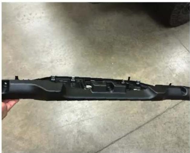
- Using a panel popper, remove the fir tree body clip on the front corner edge on the passenger side ROPs. Then carefully unclip the panel and remove from the vehicle. Repeat process on driver side.
NOTE - Some vehicles may have noise canceling microphone mounted to these panels that will need to be disconnected.

Disassembly Instructions
- Unclip the two panels on the b-pillar sill panel.
- Unclip the b-pillar sill panel.

- Disconnect the OEM wiring connector from the OEM soundbar.

Installation Instructions
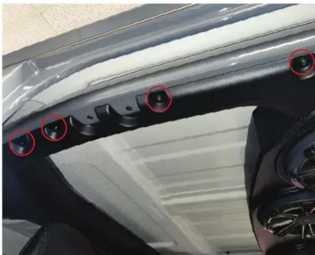
- Remove three bolts with a 10mm socket on the passenger side. Repeat on driver side.
- Then remove soundbar from vehicle.
NOTE - We recommend having additional helping hands for this step

- Install the MB Quart Soundbar using the bolts from the previous step. Loosely install three bolts on the passenger side and repeat on driver side. Once all six bolts are installed - go back and tighten with a 10mm socket.

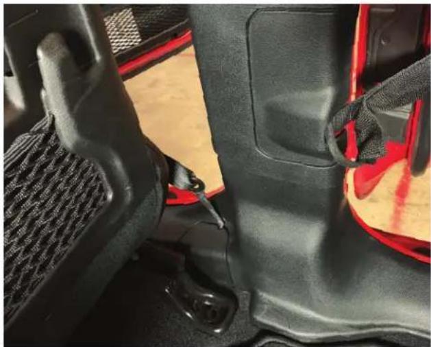
- Route the soundbar wiring along the OEM wiring toward the passenger b-pillar sill panel and then down to the floor. Secure wiring with zip ties.

Installation Instructions
- With wiring secured down the b-pillar, route wiring toward your amplifier and make appropriate wiring connections.

- All of the MB Quart Soundbars are designed to plug into a NA2-400.2 or NA2-400.2RC amplifier. If connecting to a different amplifier, the connector can be cut off and wired according to the diagram on the right.

| Line No. | Color Function | |
| 1 | White Left Speakers, Positive (+) | |
| 2 | White/Black Left Speakers, Negative (-) | |
| 3 | Gray Right Speakers, Positive (+) | |
| 4 | Gray/Black Right Speakers, Negative (-) | |
| 5 | Red LED, Negative (-) | |
| 6 | Green Green LED, Negative (-) | |
| 7 | Blue | Blue LED, Negative (-) |
| 8 | Black | LED, Positive (+) +12v |
Installation Instructions
- If your MB Quart Soundbar has the RGB lighting option, then the Black wire will be connected to a positive +12 volt source. The Red, Green, and Blue wires would need to see a negative (-) or ground for that color(s) to be shown and the chart to the right gives you different combinations. For the best control and choices, it is recommended to connect to an external RGB controller.
| Wire Color Connected to Negative (-) | LED Color Shown |
| Red Red | |
| Green Green | |
| Blue Blue | |
| Red & Green Yellow | |
| Red & Blue Purple | |
| Green & Blue Aqua | |
| Red, Green, & Blue White |
• Install the b-pillar sill panel in the vehicle.
- Clip the two panels back into the b-pillar sill panel.
- Install passenger side corner panel by clipping back into the vehicle. Then install the fir tree clip. Repeat process on driver side.

NOTE - If your vehicle has the noise canceling microphone reinstall and connect.

Installation Instructions
- Pass the dome light connector through the dome light hole on the middle ROPs cover. Then clip the middle ROPs cover to the soundbar.

• Install dome light wiring connector into the dome light and then clip the dome light into the middle ROPs cover.

• Install three screws into the front of the middle ROPs cover.

Installation Instructions
- Install the passenger side ROPs panel by carefully sliding into place and then clipping. After, secure with two T25 Torx.

• Install three or four T25 Torx on the passenger side rear ROPs. Repeat the last two steps on the driver side.
- Carefully install the passenger side front ROPs panel by sliding into place then snapping the clips into the final position. Install two T25 Torx screws.

Installation Instructions
• Install two T25 Torx screws on passenger side front ROPs panel. Repeat last two steps on driver side.

• Install the driver and passenger side front roof per vehicles owner manual.
- Reconnect the negative battery terminal.


MBQuart.com
#MUSIC DEFINED
WARRANTY
Maxxsonics, LLC. warrants this product, to the original consumer purchaser, to be free from defects in material and workmanship for a period of one (1) year from the date of purchase. Maxxsonics, LLC. will, at its discretion, repair or replace defective products during the warranty period. Components that prove to be defective in materials and workmanship under proper installation and use must be returned to the original authorized Maxxsonics, LLC. retailer from where it was purchased. A photocopy of the original receipt must accompany the product being returned. The costs associated with removal, re-installation and freight are not the responsibility of Maxxsonics, LLC. This warranty is limited to defective parts and specifically excludes any incidental or consequential damages connected therewith. To view the full warranty, please visit the website.
MB Quart products are designed and engineered in the USA by
MAXXSONICS®
www.maxxsonics.com
MBQJ-48HRGB - MBQJ-48CRGB MBQJ-48H - MBQJ-48C - MBQJ-48E REV 01

Brand : MB QUART
Model : MBQJ-48E
Category : Loudspeaker