SSRVS-7742 - Jokofu Federal - Free user manual and instructions
Find the device manual for free SSRVS-7742 Federal in PDF.

User questions about SSRVS-7742 Federal
0 question about this device. Answer the ones you know or ask your own.
Ask a new question about this device
Download the instructions for your Jokofu in PDF format for free! Find your manual SSRVS-7742 - Federal and take your electronic device back in hand. On this page are published all the documents necessary for the use of your device. SSRVS-7742 by Federal.
USER MANUAL SSRVS-7742 Federal
The Signature of Quality®
Installaon & Operaon Instrucons
Refrigerated SSRPF & SSRVS Models

natural_image
Exterior view of a modern refrigerated display cabinet filled with various packaged food items (no visible text or labels)Federal Industries
215 Federal AVE
Belleville, WI 53508
Toll Free: (800) 356-4206
WI Phone: (608) 424-3331
Fax: (608) 424-3234
Contents
(1) Introducon 4
1.1 Serial Number....4
(2) Warning Labels & Safety Instrucons....5
(3) Pre-Installaon Procedures 6
3.1 Inspecon for Shipping Damage 6
(4) General Electrical & Grounding 7
4.1 Cord Connected....7
4.2 Permanent Connected (Opon)....7
(5) Installaon Instrucons 8
5.1 Locang the Display Case....8
5.2 Removing Case From Shipping Skid and General Installaon 8
5.3 Cleaning....8
5.4 Refrigeraon System....8
5.4.1 Self Contained Models....8
5.4.2 Remote Models 8
5.5 Evaporator Condensate Drain Tube 9
5.6 Condensate Pump 9
(6) Shelving Installaon & Removal 10
6.1 Metal Shelves 10
6.2 Glass Shelf Installaon (OPTIONAL) 12
(7) SSRPF CASE REAR DOORS (OPTION) 14
10.2.2 Powering on control 20
10.2.3 Adjusting the set point 21
10.2.4 Entering manual defrost mode.... 21
10.2.5 Error codes.... 21
10.3 Inial Startup.... 21
10.4 Placing Product in Case 23
(11) Periodic Maintenance....24
11.1 Cleaning Condenser Coil.... 24
(12) Cleaning Instrucons 25
12.1 Daily Cleaning 25
12.2 Weekly Cleaning 26
12.3 Weekly Exterior Cleaning 28
(13) Sale & Disposal.... 29
13.1 Owner Responsibility 29
(14) Service Informaon....30
14.1 Pre-Service checklist.... 30
14.1.1 Case does not operate.... 30
14.1.2 Lights do not operate 30
14.1.3 Case temperature too warm (product is exceeding 41^ F) 30
14.2 Special Service Instrucons.... 31
14.3 Refrigeraon & Electrical Data 31
14.4 Electronic Control Operaon 32
14.4.1 Operaon....32
14.4.2 Defrost Cycle 32
14.5 Control Parameters 32
14.6 Error Codes.... 33
14.7 Refrigeraon Operaon 33
14.7.1 Self Contained Models.... 33
14.7.2 Remote Models 34
(15) Wiring Diagrams.... 35
15.1 Self Contained 35
15.2 Remote 37
(16) Replacement Parts 38
Tables
Table 1 - Shelf Loading Limits ...... 23
Table 2 - Electrical Rangs 31
Table 3 - Control Parameters.... 32
Table 4 - Error Codes and Resoluons.... 33
Table 5 - Temperature Probe Common Resistance Chart 33
(1) INTRODUCTION
Thank you for purchasing a Federal Industries display case. This manual contains important instrucons for installing and servicing the SSRPF and SSRVS refrigerated self-service merchandisers. A repair parts list and wiring diagram are also included in the manual. Read all of these documents carefully before installing or servicing your case.
 | NOTICERead this manual before installing your case. Keep this manual and refer to it before doing any service on the equipment. Failure to do so could result in personal injury or damage to the case. |
 | NOTICEInstallaon and service of the electrical components in the case must be performed by a licensed electrician.The porons of this manual covering components contain technical instrucons intended only for persons qualified to perform electrical work. |
 | DANGERImproper or faulty hookup of electrical components in the case can result in severe injury or death.All electrical wiring hookups must be done in accordance with all applicable local, regional, or naonal standards. |
1.1 SERIAL NUMBER
Record the model and serial numbers of the case for easy reference. Always refer to both model and serial numbers in your correspondence with Federal regarding the case.
Case Model ____ Serial Number ____
Condensing Unit Model ____ Serial Number ____
This manual cannot cover every installaon, use, or service situaon. If you need additional informaon, call or write us:
WARRANTY/TECHNICAL SERVICE DEPARTMENT
Federal Industries
215 Federal AVE
Belleville, WI 53508
Toll Free (800) 356-4206 / WI Phone (608) 424-3331
(2) WARNING LABELS & SAFETY INSTRUCTIONS

This is the safety-alert symbol. When you see this symbol on your case or in the manual, be alert to the potential for personal injury or damage to your equipment.
Be sure you understand all safety messages and always follow recommended precautions and safe operang procedures.

NOTICE TO EMPLOYERS:
You must make sure that everyone who installs, uses, or services your case is thoroughly familiar with all safety informaon and procedures.
Important safety informaon is presented in this secon and throughout the manual. The following signal words are used in the warning and safety messages:
| DANGER: | Severe injury or deathwilloccur if you ignore the message. |
| WARNING: | Severe injury or deathcanoccur if you ignore the message. |
| CAUTION: | Minor injury or damage to your casecanoccur if you ignore the message. |
| NOTICE: | This is important installaon, operaon, or service informaon. If you ignore the message, you may damage your case. |
The warning and safety labels shown throughout this manual are placed on your Federal Industries case at the factory. Follow all warning label instrucons. If any warning or safety labels become lost or damaged, call our customer service department at (800) 356-4206 for replacements.

text_image
CAUTION RISK OF ELECTRIC SHOCK DISCONNECT POWER BEFORE SERVICING UNIT.This label is located on the back of the display case
text_image
CAUTION HAZARDOUS MOVING PARTS DO NOT OPERATE UNIT WITH DISPLAY PANS REMOVED.This label is located below the display pan.
(3) PRE-INSTALLATION PROCEDURES
3.1 INSPECTION FOR SHIPPING DAMAGE
You are responsible for ling all freight claims with the delivering truck line. Inspect all cartons and crates for damage as soon as they arrive. If damage is noted to shipping crates, cartons, or if a shortage is found, note this on the bill of lading (all copies) prior to signing.
If damage is discovered when the case is uncrated, immediately call the delivering truck line and follow up the call with a wrien report indicang concealed damage to your shipment. Ask for an immediate inspecon of your concealed damage item. Crang material must be retained to show the inspector from the truck line.
(4) GENERAL ELECTRICAL & GROUNDING

DANGER:
Improper or faulty hookup of electrical components in the display case can result in severe injury or death.
4.1 CORD CONNECTED
All standard models are supplied with a power cord that is properly sized to the amperage requirements of the case. See the electrical data plate located on the rear le interior of the case for the proper circuit size for each case.
The cord is factory installed protruding from the boom rear corner of the case.
A separate circuit for each display case is required to prevent other appliances on the same circuit from overloading the circuit and causing malfuncon.
4.2 PERMANENT CONNECTED (OPTION)
Only a licensed electrician must perform all case electrical connecons.
All electrical wiring hookups must be done in accordance with all applicable local, regional, or naonal electrical standards.
A separate circuit for each display case is required to prevent other appliances on the same circuit from overloading the circuit and causing malfuncon.
The electrical service must be grounded upon installaon.
See the electrical data plate located at the rear of the case for proper circuit size and wire ampacity. The electrical conncon box is accessible from the rear of the case with rear grill removed.

text_image
FIELD CONNECTION BOX FLOOR CONDUIT CONNECTION 0.875 DIAMETER CONDUIT OR POWER CORD CONNECTION 0.875 DIAMETER SIX REAR PANEL SCREWS REAR BASE PANEL(5) INSTALLATION INSTRUCTIONS
5.1 LOCATING THE DISPLAY CASE
The case should be located where it is not subjected to the direct rays of the sun, heang ducts, grills, radiator, or ceiling fans, nor should it be located near open doors or main door entrances. Also, avoid locaons where there are excessive air movement or air disturbances.
The case requires a minimum of 4 inches of clearance at the rear of the unit for air discharge. Do not locate case with back ght against the wall.
No clearance is needed on sides of the unit.
5.2 REMOVING CASE FROM SHIPPING SKID AND GENERAL INSTALLATION

CAUTION:
Do not push or pull against the top end glass, or door frames and do not pull on end panels when removing the case from the skid or moving the case. Case damage or glass breakage will result.
- Remove crate top and sides and note missing or damaged items as explained in the pre-installation procedures outlined above.
- Move the case as near as possible to the nal locaon and before removing it from the shipping skid.
- Remove the (4) brackets that secure the case to the shipping skid.
- Prepare cabinet according to instrucons in this secon that pertain to your model.
- Li the case o of skid and into required posion. Only li the case from under the rear lip and front boom trim channel above the base. Note: Do not push or pull on front boom trim channel.
- The case must be level for proper drainage of defrost condensate to the condensate evaporator. Using the wrench provided level and square the case as needed by adjusting the leg leveler in each corner of base. The 6 cases also have a set of leg levelers in the center. These must be adjusted so the base is at.
- The leveled case must be sealed to the oor using a NSF listed sealant.
5.3 CLEANING
For initial setup, clean the case as outlined in the “Weekly Cleaning” secon of this manual.
5.4.1 Self Contained Models
The self-contained models are shipped from the factory with a completely operaonal 404A refrigeraon system and require no modicaons or adjustments upon installaon. Case must be installed as per the installaon secon of this manual to provide proper condenser air cooling.
5.4.2 Remote Models
The remote models are designed to use 404A refrigerant and shipped from the factory with the evaporator coil, expansion valve, sight glass, service valves and refrigerant solenoid valve. Installaon
must be performed by a licensed Refrigeraon Technician. See secon 14.7 Refrigeraon Operaon on page 33 for installaon requirements.
5.5 EVAPORATOR CONDENSATE DRAIN TUBE

WARNING TO INSTALLER:
Evaporator Condensate Drain Tube may become dislodged during shipping. Installer must check Evaporator Condensate Drain Tube upon installaon to be sure drain tube is properly seated and installed correctly.
Evaporator Drain Tube must be aached to tube protruding from boom of Evaporator Tub and must either be inside the Condensate Pan area or inside of hole of Condensate Pump.
5.6 CONDENSATE PUMP
A condensate pump is Standard on some models and Oponal on all models. Installer must check unit to see if a condensate pump has been provided with case.
WARNING TO INSTALLER:
Installer must determine if case was provided with condensate pump. Failure to hook up pump hose to drain will cause water on oor and cause a slip hazard.
Instead of using heat energy to remove condensate run o from the evaporator coil a condensate pump moves the water to a nearby drain.
- The Condensate Pump is provided with 50 of clear 1/2in OD x 3/8in ID tubing that must be run out of the base area to a drain.
- There are several drain tube exit locaons provided in the base as noted in the drawing above. Plugs or caps will need to be removed in the desired exit locaon.
- The hose can be run the enre 50 in any direcon as required, but no higher than 20 from the pump base. A check valve is provided in the pump to prevent water from owing back into the reservoir. For best eciency extend the hose level below the level of the pump base to create a siphoning eect. Never run the hose to or through an area below freezing (32°F, 0°C) or freezing water will block the tube.
(6) SHELVING INSTALLATION & REMOVAL
6.1 METAL SHELVES
text_image
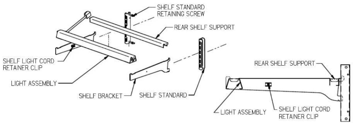
SHELF STANDARD RETAINING SCREW REAR SHELF SUPPORT SHELF LIGHT CORD RETAINER CLIP LIGHT ASSEMBLY SHELF BRACKET SHELF STANDARD REAR SHELF SUPPORT LIGHT ASSEMBLY SHELF LIGHT CORD RETAINER CLIP- Turn the light switch to the o posion.
- Follow the instrucons in the illustraon below and insert (1) of the shelf brackets in the desired shelf standard slot on one side of the case. Place the additional bracket in the same shelf standard slot on the opposite end of case. The bracket with a clear plasc cord retainer clip must be on the side with the shelf light.
-
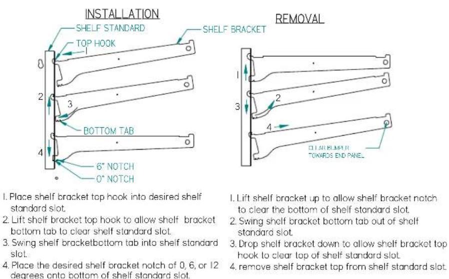
Place shelf bracket top hook into desired shelf standard slot
-
Lift shelf bracket top hook to allow shelf bracket bottom lab to clear shelf standard slot.
-
Swing shelf bracketbottom tab into shelf standard slot.
-
Place the desired shelf bracket notch of 0, 6, or 12 degrees onto bottom of shelf standard slot.
-
Lift shelf bracket up to allow shelf bracket notch to clear the bottom of shelf standard slot.
-
Swing shelf bracket bottom tab out of shelf standard slot.
-
Drop shelf bracket down to allow shelf bracket top hook to clear top of shelf standard slot
-
remove shelf bracket top from shelf standard slot.
-
Hang one end of the shelf light housing on the front notch of a shelf bracket and then the other end of the shelf light housing on the notch of the shelf bracket on the opposite end. Note: On models without shelf lights, use a shelf support instead of a shelf light housing.
- Push shelf light cords into plasc shelf cord retainer clip located on the inside of the shelf bracket.
- Remove the cap from the appropriate female light sockets. Important: Grip each side of cap rmly and wiggle and pull cap straight out of socket. Do not roll cap during removal. Incorrect removal of cap may cause damage to electrical conncon
natural_image
Pure mechanical diagram showing two input arrows entering a processing block (no text or symbols)RIGHT

natural_image
Abstract geometric diagram with intersecting black lines forming a cross pattern (no text or symbols)WRONG
- If the socket is not being used for a shelf light, the cap must be plugged into socket for enre light system to operate.
- Plug in shelf light by aligning the male pins on the appropriate shelf light cord plugs with the female light sockets and push together. IMPORTANT: Do not roll plug during inseron.
- Hang one end of the shelf support on to the rear notch of one shelf bracket and then on the rear notch of the shelf bracket on the opposite side.
- Place supplied shelving onto shelf supports as outlined in the appropriate "Shelf Installaon" secon of this manual.
- Removal of shelving is performed by following steps in reverse order.
- The shelf standards are removable from case by removing the (2) shelf standard retaining screws holding them to the inside wall of case.
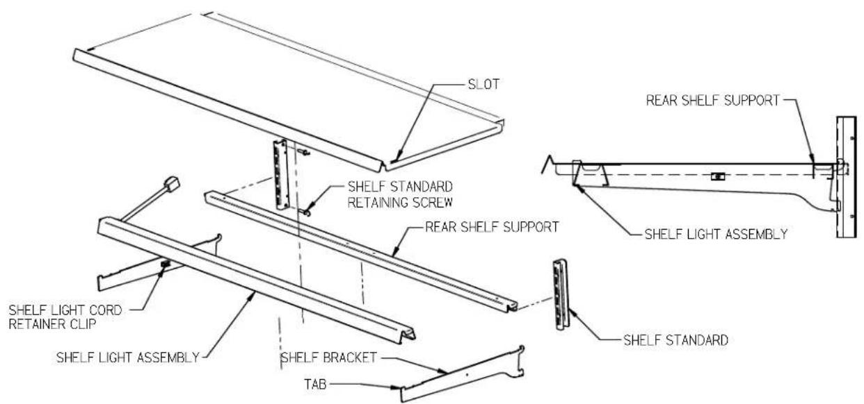
Solid Shelf Installaon
text_image
SLOT SHELF STANDARD RETAINING SCREW REAR SHELF SUPPORT REAR SHELF SUPPORT SHELF LIGHT ASSEMBLY SHELF LIGHT CORD RETAINER CLIP SHELF LIGHT ASSEMBLY SHELF BRACKET TAB SHELF STANDARD-
Install shelf brackets & shelf supports as described in Shelf Bracket & Supports Installaon Secon of this manual.
-
Place the front of metal shelf onto front shelf light. (On front shelf support for models without shelf lights). The tab on end of shelf bracket must go through slot in front of shelf.
-
Place the back of shelf over the back of the rear shelf support.
6.2 GLASS SHELF INSTALLATION (OPTIONAL)

text_image
PRODUCT STOP GLASS SHELF GLASS SHELF RETAINER CLIP BACK OF CLIP ONE INCH FROM BACK OF GLASS SHELF SHELF STANDARD RETAINING SCREW SHELF STANDARD REAR SHELF SUPPORT OPTIONAL BOTTOM SECTION GLASS SHELF PLACE GLASS SHELF RETAINER CLIP OVER REAR SHELF SUPPORT SHELF LIGHT ASSEMBLY SHELF BRACKET PRODUCT STOP TOP VIEW CLIP LOCATED ONE INCH FROM BACK EDGE IN FAR CORNER OF GLASS SHELF. CLIPS FIELD INSTALLED TO GLASS.-
For rst me installaon each (2) glass shelf retainer clips to each glass shelf in locaon shown in illustraon one inch from back of glass as shown. Clean area of glass where glass shelf holder is to be located with rubbing alcohol and let air dry before installing shelf glass holder. Remove backing from tape located on at side of glass shelf holder. Posion the glass shelf holders in the (2) far corners of glass. Repeat for each glass shelf.
-
For rst me installaon each (1) product stop to each glass shelf as shown in detail above. Align the product stop edge with the edge of the glass and push the "U" poron of the product stop on to glass lip across the enre front of glass.
-
Aach a clear bumper on both sides of the light housing top surface for the front of the glass to set on. This step may have already been performed at the factory for you.
-
Place front of glass shelf onto clear bumpers on front shelf light. (On front shelf support for models without shelf lights.)
(7) SSRPF CASE REAR DOORS (OPTION)
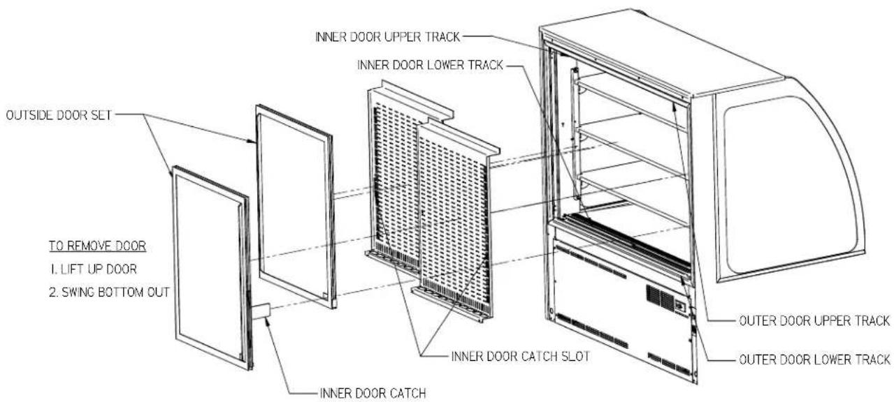
text_image
OUTSIDE DOOR SET TO REMOVE DOOR 1. LIFT UP DOOR 2. SWING BOTTOM OUT INNER DOOR UPPER TRACK INNER DOOR LOWER TRACK INNER DOOR CATCH SLOT INNER DOOR CATCH OUTER DOOR UPPER TRACK OUTER DOOR LOWER TRACK- Start with the outer "outside door" and li the door upward unl the boom edge of door clears the lower track and then swing the boom of the door outward and down and out of upper track.
- Remove the outer "inside door" using the same procedure.
- The inner door set can then be removed using the same procedure starng with the inner "outside door" followed by the inner "inside door".
- Reverse this procedure for door reinstallaon starng with the inner "inside door" followed by the inner "outside door". Check that all the doors slide freely.
- Replace the outside "inner door" and the outside "outer door". Be sure to slide the inner door catch into the inner door catch slot for each le and right side door.
Note: All four rear doors are "not" interchangeable. Each rear door must be replaced in each doors original locaon.
The night curtain rolls up and is stored on the back top edge of the case as shown in rst view.
The curtain can be used to cover the front open display area as shown in the second view above.
OPENING SSRPF NIGHT CURTAIN:
Standing in back of the case, grab the night curtain strap and pull the rolled night curtain up and over the top and front of the case. Aach the snap located under the night curtain strap on to the snap located on the case front lower panel
CLOSING SSRPF NIGHT CURTAIN:
From front of case grab the night curtain strap and detach the snap located in the case front lower panel. Allow the night curtain to roll up over the top and back of the case. Note: The 59" and 77" models have (2) night curtains.
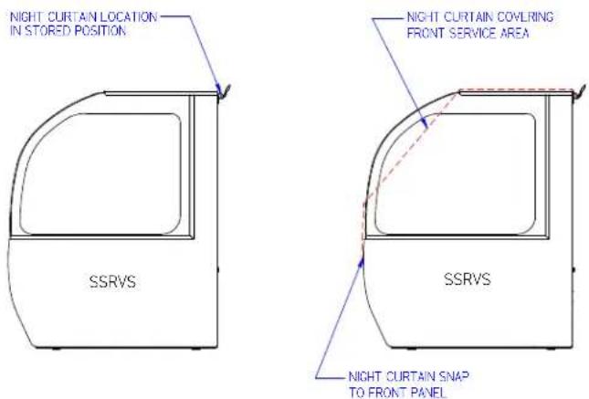
text_image
NIGHT CURTAIN LOCATION IN STORED POSITION NIGHT CURTAIN COVLRING FRONT SERVICE AREA SSRVS SSRVS NIGHT CURTAIN SNAP TO FRONT PANELOPENING SSRVS NIGHT CURTAIN:
Standing in back of the case, grab the night curtain strap and pull the rolled night curtain up and over the top and front of the case. Aach the snap located under the night curtain strap on to the snap located on the case front lower panel
CLOSING SSRVS NIGHT CURTAIN:
From front of case grab the night curtain strap and detach the snap located in the case front lower panel. Allow the night curtain to roll up over the top and back of the case.
Note: The 59" and 77" models have (2) night curtains.
(9) SECURITY NIGHT COVER (OPTION)

text_image
LOCK HANDLE (SHOWN IN LOCK POSITION) LOCK HANDLE (SHOWN IN LOCK POSITION) LOCK HANDLE CATCH LOCK HANDLE CATCH SECURITY NIGHT COVER GRAB HANDLE GRAB HANDLE "U" RETAINER CLIP FRONT CLEAR DEFLECTOR "U" RETAINER CLIP ON CENTER (ON SOME MODELS) "U" RETAINER CLIPREMOVAL:
- Unlock the lock handles and turn handles vercal to disengage from lock handle catches.
- Grab the front grab handles and li the cover straight up out of the case opening.
INSTALLATION:
- Turn the lock handle so the latch handle is vercal to the top of the case.
- Holding the grab handles place the boom ange of the security night cover inside the "U" retainer clips located on each side of case opening behind the front clear deector. There also may be a "U" retainer clip in the center of the case that must also engage the security night cover ange.
- Set the top angle of the security cover down against the top glass handle.
- Turn the lock handles so they engage the lock handle catches and use the key to lock them in place.
IMPORTANT: Cleaning the Acrylic plasc security night cover require special care to prevent hazing of material. Lightly dust (not wipe) the surface with clean so cloth. Then the surface can be wiped carefully with a so, wet cloth or chamois. The cloth or chamois must be kept free of grit by frequently rinsing in clean water. Grease and oil can be removed with kerosene. Do not use window cleaners or kitchen scouring compounds. DO NOT use solvents such as Acetone, Benzene, Carbon Tetrachloride, and Lacquer Thinners. A
spray wax such as Pledge or Maguire's polish can be applied and wiped with a clean so cloth. The wax tends to ll in and hide small scratches
(10) OPERATING INSTRUCTIONS
10.1 USER CONTROLS OVERVIEW
text_image
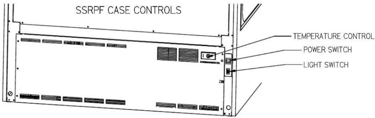
SSRPF CASE CONTROLS TEMPERATURE CONTROL POWER SWITCH LIGHT SWITCH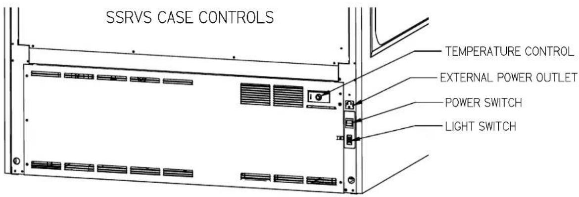
text_image
SSRVS CASE CONTROLS TEMPERATURE CONTROL EXTERNAL POWER OUTLET POWER SWITCH LIGHT SWITCHPower Switch
The unit has a power switch that turns o power to the enre unit, including the condensate evaporator and the lights.
Light Switch
The unit has a light switch that turns on and o the interior lights of unit.
Temperature Control
Located in the rear grille of the display case, the temperature control allows the user to adjust the temperature of the display merchandiser to their needs.
10.2 USING THE ELECTRONIC CONTROL
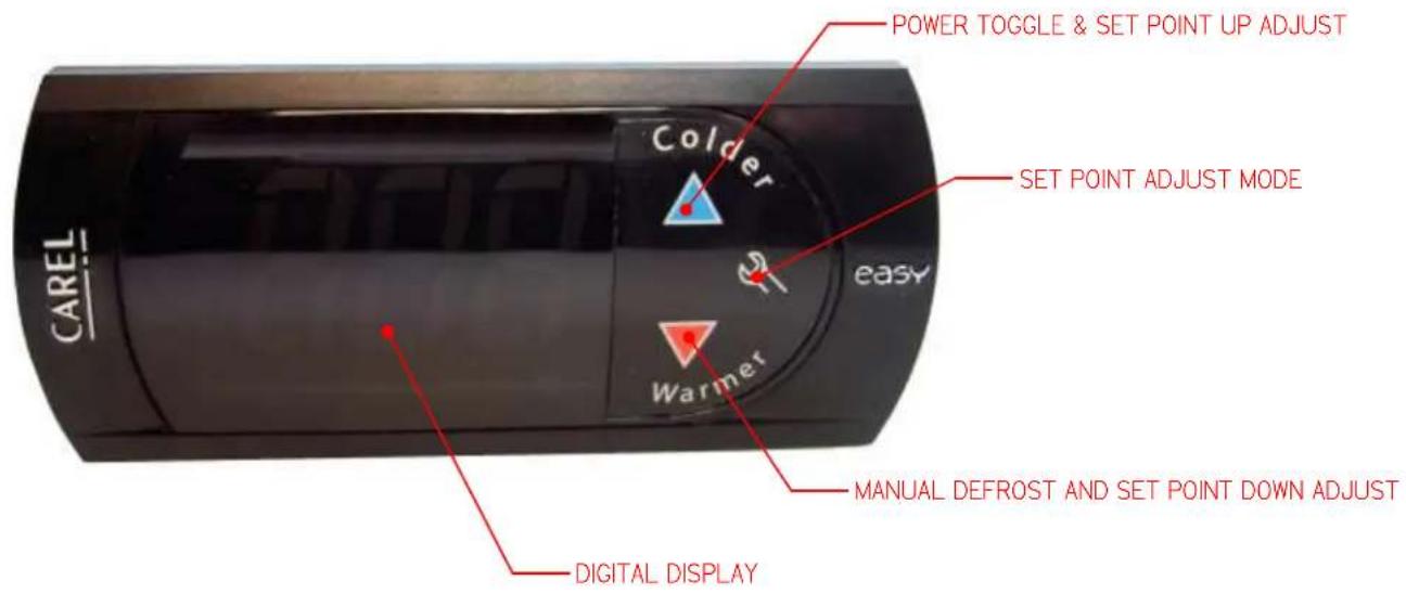
text_image
POWER TOGGLE & SET POINT UP ADJUST Colder SET POINT ADJUST MODE easy Warmer CAREL DIGITAL DISPLAY MANUAL DEFROST AND SET POINT DOWN ADJUST10.2.1 Button and Display Overview
 | Press and hold this buon for 3s to turn system on (if o) or o (if on).Also used to adjust set point when in set point adjust mode |
 | Press to enter set point adjust mode, conrm set point changes, and mute alarms. |
 | Press and hold this buon for 3 seconds to initiate a manual defrost (and cancel defrost if initiated), also adjusts set point down when in set point adjust mode |
 | Press both buons simultaneously to check air stream probe temperature. This is not an indicator of product temperature. |
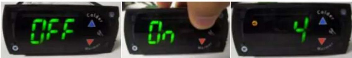
10.2.2 Powering on control
To turn power on to the refrigeraon system press and hold, for three seconds, the blue up arrow on the control's keypad. The keypad will read "On" while the buon is depressed. When the system powers on, the display will read the current set point (a number "1" through "9"). The orange compressor run indicator will illuminate on the display.
text_image
OFF On 410.2.3 Adjusting the set point
The set point is what determines how cold the display case will hold food and beverage. To adjust the set point press and hold the wrench buon unl the display begins to ash a number (three seconds). Then use the up and down arrows of the keypad to scroll through the set point opons. There are nine (9) available set points, the higher the number of the set point name, the colder the display case will run, with seng "9" being the coldest and seng "1" being the warmest. Once you have chosen your desired seng press the wrench buon again to conrm your choice.

text_image
SET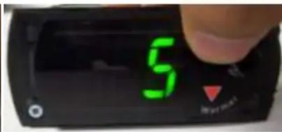
text_image
5 My own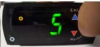
text_image
5 Control Balance10.2.4 Entering manual defrost mode
In order to initiate a manual defrost press and hold the red down arrow for 3s. The control will read "dEF" while the buon is being held. The defrost is initiated when the orange snowake appears on the control display.

text_image
DEF Colder
text_image
Colder M R10.2.5 Error codes
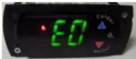
It is possible for error codes to be displayed on the control screen. In the event of a malfuncon an alarm will sound and a red ringing bell will be displayed on the screen. An error code or codes will ash intermiently on the display. If there are mulple codes, the display will connuously cycle through them. The following photo shows error code “E0” as an example next to the red bell.
text_image
ED CalderYou may mute the alarm by pressing and releasing the wrench buon. The red ringing bell and all error codes will sll be displayed. When the fault is remedied the control will return to normal operaon and will automacally clear the codes from the display.
10.3 INITIAL STARTUP
Aer all the checks outlined in the installaon secon of this manual have been made, the case is ready to be put into service. Turn on the Power at the breaker box and ip the Power Switch and Light Switch on unit to the on posion. Also ensure that the control is powered on as described above in "10.2.2".
At start up from a warm unit, it is recommended that the temperature control is set to a warmer seng, such as 1. Aer the unit has gone through several cycles, adjust the control to a mid range seng, then to a colder seng if necessary to maintain desired product temperature

NOTICE:
This refrigerated display case is designed to operate in a maximum environment of 75^ F ( 23.9^ C) and 55% relave humidity. Exceeding these limits will cause poor case performance and excessive sweang.
10.4 PLACING PRODUCT IN CASE
- Do not exceed weight limits shown in the table below when loading product into the display case.
Table 1 - Shelf Loading Limits
| Model | Top Shelf | Middle Shelf | Boom Shelf | Display Deck |
| SSRPF/VS36 | 80lbs (36kg) | 100lbs (45kg) | 120lbs (55kg) | 165lbs (75kg) |
| SSRPF/VS50 | 120lbs (55kg) | 140lbs (64kg) | 170lbs (77kg) | 240lbs (109kg) |
| SSRPF/VS59 | 140lbs (64kg) | 170lbs (77kg) | 210lbs (95kg) | 290lbs (132kg) |
| SSRPF/VS77 | 180lbs (82kg) | 230lbs (105kg) | 270lbs (123kg) | 390lbs (177kg) |
- Determine desired shelving locaon before placing product in case. Product must be removed to readjust shelf locaon and angle.
- Do not overhang the front or rear of shelves with product. Improper clearance in front and rear of shelf will block the refrigerated air ow and will cause product loss.
- Do not block the slots along the front and rear air discharge slots. Covering these slots will block the refrigerated air ow and will cause product loss.
- The display deck is removable for cleaning and can become dislodged in shipment. To ensure proper airrow and performance of the case, make sure that the display deck is pushed completely down into the plasc evaporator tub.
- Allow refrigerated models to run for at least two hours before placing pre-chilled product into unit.

NOTICE:
Case must be stocked with pre-chilled product only. Product should be at or below 40^ F ( 4.5^ C) before adding it to the display case. Use a refrigerator to pull down product that is above 40^ F ( 4.5^ C). This display case is a temperature holding product only. It will not pull down product that is above the recommended temperature.
(11) PERIODIC MAINTENANCE
11.1 CLEANING CONDENSER COIL
NOTICE:
Condenser coil must be cleaned a minimum of twice per month to insure proper refrigeration performance and prevent compressor failure. Failure to clean condenser coil will void condenser warranty.
It is very important that the condenser coil is cleaned twice per month to ensure proper refrigeraon performance and to prevent compressor failure. Failure to clean condenser coil will void condenser warranty.
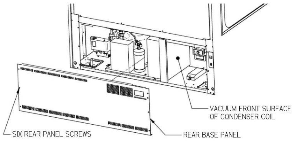
- Disconnect power to the unit
- Remove the rear base panel located on the back of the unit by removing the rear panel retaining screws.
- Carefully vacuum the front surface of condenser coil. Take care not to bend coil ns with vacuum cleaner nozzle. A brush aachment works well to prevent this.
- Reinstall rear panel and retaining screws.
text_image
VACUUM FRONT SURFACE OF CONDENSER COIL REAR BASE PANEL SIX REAR PANEL SCREWSFigure 1 - Condenser Cleaning
(12) CLEANING INSTRUCTIONS
12.1 DAILY CLEANING
The case should be cleaned thoroughly, as described in the weekly cleaning secon, before it is used for the rst me.
 | NOTICE:Avoid splashing or soaking any electrical components with water to prevent electrical damage to the case. |
 | NOTICE:Shut o lights and power switches and remove all product from case. Allow sucient me for the unit to reach room temperature before proceeding with cleaning. |
 | NOTICE:Remove all product from case before proceeding with cleaning procedure. |
 | NOTICE:Acrylic front air deector requires special washing procedures to prevent hazing and yellowing of material. |
 | NOTICE:This case is not designed to be cleaned by using. |
Note: For major spills or foreign material buildup perform the weekly cleaning instrucons.
Note: Detergents are not recommended and do not use abrasive cleaners or pads to prevent scratching of surfaces.
- Clean all foreign materials from the door opening if supplied.
- Wipe complete interior of both the upper & lower areas of case using a damp cloth.
- To allow easier access to clean upper secon interior lt the upper front glass open. Tilt the front glass up by standing in front of the case and grabbing the handle at the boom of the glass and liing the boom of the glass upward. The glass can then be cleaned with common window cleaners. Close the glass by pulling the front handle of glass down to the closed posion.
- The remaining exterior surface should be wiped down using any ammoniated cleaners or soapy warm water.
- IMPORTANT: Cleaning the clear acrylic plasc front air deector require special care to prevent hazing and yellowing of material. Lightly dust (not wipe) surface with clean so cloth. Then the surface can be wiped carefully with a so, wet cloth or chamois. The cloth or chamois must be kept free of grit by frequently rinsing in clean water. Grease and oil can be removed with kerosene. Do not use window cleaners or kitchen scouring compounds. DO NOT use solvents such as Acetone, Benzene, Carbon
Tetrachloride, and Lacquer Thinners. A spray wax such as Pledge or Maguire's polish can be applied and wiped with a clean so cloth. The wax tends to ll in and hide small scratches.
12.2 WEEKLY CLEANING

text_image
SHELF STANDARD HONEYCOMB AIR DIFFUSER SHELF SHELF SHELF FAN SHROUD ASSEMBLY RETAINER LATCH SHELF STANDARD SHELF BRACKET SHELF BRACKET FAN SHROUD ASSEMBLY FAN SHROUD ASSEMBLY RETAINER LATCH DISPLAY DECK CLEAR AIR DEFLECTOR SHELF BRACKETThis procedure is recommended on a weekly basis. It may need to be performed more often if necessary to maintain a clean, sanitary case. The case should be cleaned to this procedure before using the rst me.
 | NOTICE:Avoid splashing or soaking any electrical components with water to prevent electrical damage to the case. |
 | NOTICE:Shut o lights and power switches and remove all product from case. Allow sucient me for the unit to reach room temperature before proceeding with cleaning. |
 | NOTICE:Remove all product from case before proceeding with cleaning procedure. |
 | NOTICE:This case is not designed to be cleaned by using. |
- The side glass can be cleaned with common window cleaners.
- Remove food pan catch tray by liing it out of top of case. Clean all foreign material from around and under the food pan catch tray. Clean food pan catch tray using warm soapy water and a brush.
-
If supplied with Rear Door Opon, remove both inner & outer rear doors as described in the "Door Removal" secon of this manual.
-
Clean all foreign material from inner and outer rear door tracks and clean both sides of the doors using warm soapy water and a brush. Apply a light lm of lubricant such as PAM to door tracks to make the doors operate smoother.
- Remove interior shelving from unit as described in the "Shelving Installaon and Removal" secon of this manual. Remove both shelf standards from interior of case by removing the (2) thumbscrew from top and boom of each standard.
- Clean all shelves, shelf supports, shelf light housings, shelf brackets, shelf standards using warm soapy water and a brush. Rinse thoroughly and allow to dry.
- Li the display deck(s) up and out of evaporator tub.
- Remove the fan shroud assembly by liing (2) black tabs up on fan shroud assembly retainer latch at each end of the front of the fan shroud and removing the thumb screws from along the rear lip of the fan shroud. Li the fan shroud assembly and reach in and unplug the evaporator fan motor cord(s). Li fan shroud assembly out of tub.
- Clean the display deck(s) using warm soapy water and a brush. Rinse thoroughly and allow to dry. Wipe o fan shroud assembly (do not rinse or submerge fan motors).
- Clean the enre interior of the case using warm soapy water. Flush foreign material from drain area. Wipe o all soapy water with a damp cloth and allow to dry. (DO NOT use solvents such as Acetone, Benzene, Carbon Tetrachloride, and Lacquer Thinners)
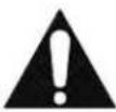
- Remove the honeycomb air diuser(s) from upper air duct track. Loosen thumb screws on Retainer located behind diuser. Retainer will drop down allowing diuser to be pulled out of case.
text_image
THUMB SCREW (3) RETAINER HONEYCOMB AIR DIFFUSER-
Clean honey comb air diuser with warm soapy water and a brush. Rinse thoroughly and allow to dry.
-
Remove the clear plasc front air deector by liing it up and out of case.
IMPORTANT: Cleaning the Acrylic plasc front air deector require special care to prevent hazing and yellowing of material. Lightly dust (not wipe) the surface with a clean so cloth. Then the surface can be wiped carefully with a so, wet cloth or chamois. The cloth or chamois must be kept free of grit by frequently rinsing in clean water. Grease and oil can be removed with kerosene. Do not use window cleaners or kitchen scouring compounds. DO NOT use solvents such as Acetone, Benzene, Carbon
Tetrachloride, and Lacquer Thinners. A spray wax such as Pledge or Maguire's polish can be applied and wiped with a clean so cloth. The wax tends to ll in and hide small scratches.
- Reassemble all components in reverse order.
NOTE: Depending on the amount of usage and spillage of foreign material, some fasteners may have to be removed and parts disassembled to allow proper cleaning of the unit.
12.3 WEEKLY EXTERIOR CLEANING
- Clean the front and end glass using any common window cleaner.
- The exterior surfaces should be wiped down using any ammoniated cleansers or warm soapy water.
(13) SALE & DISPOSAL
13.1 OWNER RESPONSIBILITY
If you sell or give away your Federal Industries case you must make sure that all safety labels and the Installaon-Service Manual are included with it. If you need replacement labels or manuals, Federal Industries will provide them free of charge. Contact the customer service department at Federal Industries at (800) 356-4206.
The customer service department at Federal Industries should be contacted at the me of sale or disposal of your case so records may be kept of its new locaon.
If you sell or give away your Federal Industries case and you evacuate the refrigerant charge before shipment. Federal Industries recommends that the charge be evacuated into a recovery system to prevent the possibility of HFC's from being released into the atmosphere.
(14) SERVICE INFORMATION

CAUTION:
RISK OF ELECTRIC SHOCK!!!
DISCONNECT POWER BEFORE SERVICING UNIT!!!
Before any service work is performed on the case, make sure all power is disconnected to the case.
Service problems or request for repair parts from authorized service agencies, trained service personnel, or owners should be referred to:
CUSTOMER SERVICE DEPARTMENT
Federal Industries
215 Federal AVE
Belleville, WI 53508
Toll Free: (800) 356-4206 / WI Phone (608) 424-3331
Fax: (608) 424-3234
14.1 PRE-SERVICE CHECKLIST
You may avoid the cost and inconvenience of an unnecessary service call by rst reviewing this checklist of frequently encountered situations that can cause unsasfactory case performance.

CAUTION:
Before servicing case, turn o power at the main breaker of fuse box.
14.1.1 Case does not operate
☐ Check for disconnected power supply.
☐ Check for tripped breaker or blown fuse.
☐ Check that power switch is on.
14.1.2 Lights do not operate
□ Check that light switch is on.
☐ Shelf light: Check that shelf light cords are ght in the sockets
☐ Shelf light: Ensure all open sockets are lled with either shelf light cord plugs or dummy caps aached to socket.
14.1.3 Case temperature too warm (product is exceeding 41^ F)
☐ Check that the cold air inlet and outlet slots are not blocked.
☐ If supplied with rear door opon be sure that the rear doors are closed and ghtly sealed
☐ Check for blocked or dirty condenser coil ns and clean them (see "11.1 Cleaning Condenser Coil" page 24).
☐ Check that there is no paper or foreign material blocking the evaporator, and if so remove it.
☐ If the evaporator coil is blocked due to excessive frost, acvate manual defrost mode on the electronic control.
☐ Check that the case is given the proper clearance behind the rear grille (see secon 5.1 "Locang the Display Case" page 8)
☐ Check that there is no air movement around case causing disrupon to the air curtain. Such as ceiling fans, heang/AC air ducts, exterior doors, etc.
14.2 SPECIAL SERVICE INSTRUCTIONS
There are rare occasions when the refrigerant charge must be evacuated from a case in order to perform service work. In those situations, Federal Industries recommends that the refrigerant charge be evacuated into a recovery system to prevent the possibility of hydrouorocarbons (HFC's) from being released into the atmosphere.
If moisture or liquid is observed around or under a Federal Industries case, an immediate investigaon should be made by qualified personnel to determine the source of the moisture or liquid. The investigaon made should determine if the case is malfunconing or if there is a simple housekeeping problem.
Moisture or liquid around or under a case is a potenal slip/fall hazard for persons walking by or working in the general area of the case. Any case malfuncon or housekeeping problem that creates a slip/fall hazard around or under a case should be corrected immediately.
Table 2 - Electrical Rangs
| MODEL | SELF CONTAINED | REMOTE | |||||
| 404A REFRIG. | VOLTAGE | AMPERAGE | CORD STYLE | VOLTAGE | AMPERAGE | CORD STYLE | |
| SSRPF3652 SSRVS3642 | 30 oz | 120/60/1 | 14.3 | 20AMP NEMA 5-20 | 120/60/1 | 3 | 15AMP NEMA 5-15 |
| SSRPF5052 SSRVS5042 | 32 oz | 230/60/1 | 9.5 | 15AMP NEMA 6-15 | 120/60/1 | 3 | 15AMP NEMA 5-15 |
| SSRPF5952 SSRVS5942 | 34 oz | 230/60/1 | 14.5 | 20AMP NEMA 6-15 | 120/60/1 | 2 | 15AMP NEMA 5-15 |
| SSRPF7752 SSRVS7742 | 34 oz | 230/60/1 | 14.5 | 20AMP NEMA 6-20 | 120/60/1 | 2 | 15AMP NEMA 5-15 |
14.4 ELECTRONIC CONTROL OPERATION
This unit is equipped with an electronic temperature control. The control parameters are set at the factory and cannot be manually changed in the eld. The pre set control parameters are listed on the chart in the Sengs Chart below.
14.4.1 Operation
The control uses two sensors, one located in the air stream and one located on the evaporator coil. The sensor located in the air stream is referred to as the temperature control sensor. The sensor located on the evaporator coil is referred to as the defrost probe.
The temperature control sensor is located on the plasc tub behind the evaporator coil to the le in the cold air stream. The sensor locaon is crical for proper operaon on the unit. Do not move or relocate this sensor.
The coil sensor is strapped to the evaporator coil. This sensor locaon is critical for proper operaon of the unit. Do not move or relocate this sensor.
The temperature control is set to cut in at 39^ F ( 3.9^ C). The Temp control cuts out at 26^ F ( -3.3^ C) at the coldest seng “9” and 36^ F ( 2.2^ C) at the warmest seng “1”.
See “10.2 Using the electronic control” on page 20 for more details on using the control.
14.4.2 Defrost Cycle
The control is programmed to initiate defrost via two dierent methods. There are 3 programmed defrost cycles in the case which will initiate a defrost cycle every 8 hours. The unit does not have a me clock so the defrost cycles cannot be set for any specific me of day.
The unit also has an 'On demand' defrost feature that will initiate a defrost when the temperature dierenal between the evaporator temperature and the air temperature is more than 20^ F (11.1°C) for 5 minutes aer 30 minutes into the refrigeration cycle (e.g. if the air stream probe measures 42^ F/5.6°C or greater and the defrost probe measures 20^ F/-6.7°C or lower for ve minutes). Once initiated the defrost cycle will terminate when evaporator coil sensor reaches 43^ F (6.1°C).
If a manual defrost is required, one can be initiated by pressing and holding the down arrow for three (3) seconds. This is typically unnecessary and should only be performed if special circumstances require it.
14.5 CONTROL PARAMETERS
Table 3 - Control Parameters
| Parameter Descripon ↓ | Control Setpoint → | 1 | 2 | 3 | 4 | 5 | 6 | 7 | 8 | 9 |
| Compressor Cut in [°F] | 39.0 | |||||||||
| Compressor Cut out [°F] | 36.0 | 34.7 | 33.5 | 32.2 | 31.0 | 29.7 | 28.5 | 27.2 | 26.0 | |
| Compressor Min On Time | 10 min | |||||||||
| Compressor Min O Time | 3 min | |||||||||
| Compressor Max Run Time | 90 min | |||||||||
| Defrost Terminaon Temp [°F] | 43.0 | |||||||||
| Time to rst defrost | 8 hr | |||||||||
| Time to subsequent defrost | 8 hr | |||||||||
| Defrost duraon | 30 min | |||||||||
| Defrost on demand dierenal [°F] | 20.0 | |||||||||
| Delay for defrost on demand | 5 min | |||||||||
| Time delay to the next defrost on demand | 30 min | |||||||||
14.6 ERROR CODES
Error codes may be encountered if either the controller or the display case is malfunctioning. The following is a list of error codes that may be encountered.
Table 4 - Error Codes and Resoluons
| Code | Descripon | Cause | Resoluon |
| E0 | Temperature probe error | Probe signal is interrupted or short-circuited | Check to ensure probe wires and quick disconnect are secure in control.Check probe resistance to table below. If 0 resistance is present check wiring insulaon. If innate resistance is present check for breaks in wiring (meter will likely read overload or very high in the mega-ohm range).Ensure that probes are wired per the wiring diagram provided.Replace probe if other remedies fail, or if probe resistance deviates from “Table 5” below |
| E1 | Defrost probe error | See E0 | |
| EE | Unit parameter reading error | Operang condions | Remedy abnormal operang condions. The control is rated to operate in a range of 14 to 122°F (-10 to 50°C) and less than 90%RH non-condensing.Replace control if problem persists. |
| EF | Operang parameter reading error | See EE |
Table 5 - Temperature Probe Common Resistance Chart
| Probe Temp | Maximum Resistance [Ω] | Normal Resistance [Ω] | Minimum Resistance [Ω] |
| 32°F (0°C) | 27.83 | 27.28 | 26.74 |
| 77°F (25°C) | 10.1 | 10 | 9.9 |
| 212°F (100°C) | 1 | 0.97 | 0.94 |
14.7.1 Self Contained Models
The self-contained models are shipped from the factory with a completely operaonal 404A refrigeraon system and require no modicaons or adjustments upon installaon. Case must be installed as per the installaon secon of this manual to provide proper condenser air cooling.
The unit temperature is controlled by the electronic control outlined in the control secon of this manual.
Note: The condenser fan runs connuously.
| SSRPF3652SSRVS3642 | SSRPF5052SSRVS5042 | SSRPF5952SSRVS5942 | SSRPF7752SSRVS7742 | |
| Refrigeraon R404 Charge | 30 oz | 32 oz | 34 oz | |
| Remote Low Press. Switch Cut In | 80 psi | |||
| Remote Low Press. Switch Cut Out | 20 psi | |||
| Remote High Press. Switch Cut Out | 400 psi | |||
14.7.2 Remote Models
| Refrigeraon R404 Charge | CHARGED IN FIELD |
| Remote Low Press. Switch Cut In | 50 psi |
| Remote Low Press. Switch Cut Out | 15 psi |
| Remote High Press. Switch Cut Out | 400 psi |
The remote models are designed to use 404A refrigerant and shipped from the factory with the evaporator coil, expansion valve, sight glass, and refrigerant solenoid valve. Filter Drier must be installed in eld. Electronic control runs identical to the self contained models except the electronic control opens and closes a refrigeraon solenoid valve located on the sucon line instead of turning on and o a compressor. The solenoid valve closes and shuts o the refrigeraon ow to the unit and initiates a pump down cycle. This will allow the remote low pressure switch to open and shut o remote compressor.
The condensing unit and pressure controls are oponally supplied from the factory for remote locaon installaon. The condensing unit must be mounted and wired by the installer. The high low pressure switch must be wired in series with the compressor power supply as shown in diagram below
- Mount condensing unit indoors as close to the remote display case as praccal. The refrigeraon line should be as short as possible and must not exceed 30 feet.
- All refrigeraon and/or electrical materials between the condensing unit and display case are to be supplied by installing contractor.
- Route properly sized and designed refrigeraon lines from the condensing unit to the cabinet.
- Horizontal sucon lines should be pitched downward towards the condensing unit at least 12 " per 10' run to aid the oil drainage. A "P" trap must be installed in the sucon line at the foot of every riser to insure oil return. Dry nitrogen must be used to ow through tubing while brazing refrigeraon lines.
- Sucon line must be insulated the enre length with Armaex (or equivalent). Do not run liquid line inside insulaon with sucon line.
- The remote high/low-pressure control must be mounted, wired and set pressures by the installer.
- Leak check condensing unit, cabinet, and all connecng tubing. Cabinet and condensing unit tubing should be checked to insure no leaks occurred during shipping or from rough handling.
- Make certain all refrigeraon valves are opened and evacuate system to 500 microns. Charge the system with refrigerant type specied on the data plates.

flowchart
graph TD
    A["DISPLAY CASE"] --> B["AIR TEMP. CONTROL PROBE"]
    B --> C["EVAPORATOR COILS"]
    B --> D["DEFROST TERMINATE PROBE"]
    B --> E["EXPANSION VALVE"]
    C --> F["SIGHT GLASS"]
    D --> G["FUSED CASE POWER"]
    D --> H["LICID LINE SOLENOID VALVE"]
    E --> I["SUCTION LINE (INSULATED)"]
    E --> J["FIELD CONNECTION"]
    K["REMOTE CONDENSING UNIT"] --> L["LIQUID LINE"]
    M["FUSED POWER SUPPLY"] --> N["HOT"]
    O["REMOTE HIGH LOW PRESSURE CONTROL"] --> P["LOW"]
    Q["DRIER/FILTER"] --> R["FLUID LINE"]
    S["FUSED POWER"] --> T["Electronic Control"]
Figure 2 - Remote Refrigeration Diagram
(15) WIRING DIAGRAMS
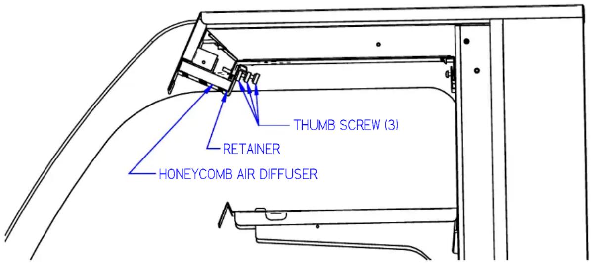
15.1 SELF CONTAINED
text_image
SSRPF/VS36XX SELF CONTAINED CASE 91-19828 REV B, 8/1/13 CORD & PLUG 120/1/60 OPTIONAL CONVENIENCE RECEPTACLE 120 VOLTTS 60 HERTZ 1 PHASE W BLK G GROUND FEED THROUGH GFCI W W BLK G G G RECEPTACLE CONDENSATE PUMP OR EVAPORATOR B R W B BLK/RIB BLK G G LED DEFROST PROBE R 10 CAREL CONTROL 4 5 6 7 TEMP PROBE R NOTE PROBE WIRING ALTERNATE CONTROL RANCOI SEE CAREL WIRING DISPLAY TOP LIGHT SHELF LIGHT QTY MAY VARY R R R R R R R R R R R R R R R R R R R R R R R R R R R R R R R R R R R R R R R R R R R R R R R R R R M FAN COMPRESSOR M EVAP. FAN DARK LINES REPRESENT (3) CONDUCTOR CORD COLOR CODE BLK=BLACK B=BLUE BRW=BROWN G=GREEN W=WHITE Y=YELLOW R=RED
text_image
SSRPF/VS50XX SELF CONTAINED CASE 91-19854 REV A, 8/1/13 CORD & PLUG 230/1/60 OPTIONAL CONVENIENCE RECEPTACLE 120 VOLTS 60 HERTZ 1 PHASE W BLK G GROUND FEED THROUGH GFCI W G BLK G G POWER SWITCH CONDENSATE PUMP OR EVAPORATOR B&W BLK/RIB BLK BLK W HI/LO PRESS SW V Y W LIGHT SWITCH BRW BLK W BLK W BLK W BLK W BLK W BLK W BLK W BLK W BLK W BLK M FAN COMPRESSOR PLUG M EVAP. FAN TOP LIGHT SHELF LIGHT QTY MAY VARY R R R R R B B B SHELF LIGHT R R B B R B B B SHELF LIGHT + PLUG - + R R R R R + R B B B + + BLK - BRW DARK LINES REPRESENT (3) CONDUCTOR CORD COLOR CODE BLK = BLACK B = BLUE BRW= BROWN G = GREEN W = WHITE Y = YELLOW R = RED
text_image
SSRPF/VS59XX, 77XX SELF CONTAINED CASE 91-19857 REV A, 8/1/13 OPTIONAL CONVENIENCE RECEPTACLE 120 VOLTS 60 HERTZ 1 PHASE W BLK G GROUND FEED THROUGH GFCI W G G G RECEPTACLE BRW BLK/RIB BLK BLK/RIB CONDENSATE PUMP OR EVAPORATOR POWER SWITCH BRLK BLK BLK BLK HI/LO PRESS SW V Y W W W W W W W W W LIGHT SWITCH COMPRESSOR BLK BLK/RIB BLK BLK/RIB BLK BLK/RIB BLK BLK/RIB BLK BLK/RIB BLK BLK/RIB BLK BLK/RIB BLK BLK/RIB BLK BLK/RIB BLK BLK/RIB BLK BLK/RIB BLK BLK/RIB BLK BLK/RIB BLK=BLACK B=BLUE BRW=BROWN DARK LINES REPRESENT (3) CONDUCTOR CORD W=WHITE Y=YELLOW G=GREEN R=RED G=FAN M FAN M EVAP. M EVAP. FAN M EVAP. NOTE PROBE WIRING W 10 ALTERNATE CONTROL RANCOI 4 5 6 7 SEE CAREL WIRING15.2 REMOTE
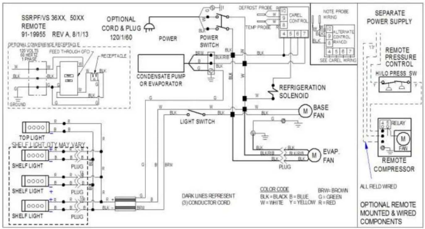
text_image
SSRPF/VS 36XX, 50XX REMOTE 91-19955 REV A, 8/1/13 OPTIONAL CONVENIENCE RECEPTACLE 120 VOLTS 60 HERTZ 1 PHASE W BLK G GROUND FEED THROUGH OPO W W BLK G POWER POWER SWITCH CONDENSATE PUMP OR EVAPORATOR BRL BLK/RIB BLK G G W BLK W BLK W BLK W BLK W BLK W BLK W BLK W BLK W BLK W BLK W BLK W BLK W BLK W BLK W BLK W BLK W BLK W BLK W BLK W BLK W BLk BLk/RIB BLk/RIB BLk/RIB BLk/RIB BLk/RIB BLk/RIB BLk/RIB BLk/RIB BLk/RIB BLk/RIB BLk/RIB BLk/RIB BLk/RIB BLk/RIB BLk/RIB BLk/RIB BLk/RIB BLk/RIB BLk/RIB BLk/RIB BLk/RIRB BLk/RIRB BLk/RIRB BLk/RIRB BLk/RIRB BLk/RIRB BLk/RIRB BLk/RIRB BLk/RIRB BLk/RIRB BLk/RIRB BLk/RIRB BLk/RIRB BLk/RIRB BLk/RIRB BLk/RIRB BLk/RIRB BLk/TOP LIGHT SHELF LIGHT OTY MAY VARY SHELF LIGHT SHELF LIGHT + PLUG R B R B R B R B R B R B R B R B R B R B R B R B R B R B R B R B R B R B R B R B R B R B R B R B R B R B R B R B R B R B R B R B R B R B R B R B R B R B R B R B R B R B R B R B R B R B R B R B R B R B R NATE PROBE WING NOTE PROBE WING WING WING WING WING WING WING WING WING WING WING WING WING WING WING WING WING WING WING WING WING WING WING WING WING WING WING WING WING WING WING WING WING WING WING WING WING WING WING WING WING WING WING WING WING WING WING WING WING WING WNG RELNATE CONTROL RANCOI 4 5 6 7 SEE CAREL WIRNG 4 5 6 7 7 7 7 7 7 7 7 7 7 7 7 7 7 7 7 7 7 7 7 7 7 7 7 7 7 7 7 7 7 7 7 7 7 7 7 7 7 7 7 7 7 7 7 7 7 7 7 7 7 13 REMOTE PRESSURE CONTROL HI/LO PRESS SW REFRIGERATION SOLENOID M BASE FAN M EVAP FAN M RELAY M FAN REMOTE COMPRESSOR ALL FIELD WIRED OPTIONAL REMOTE MOUNTED & WIRED COMPONENTS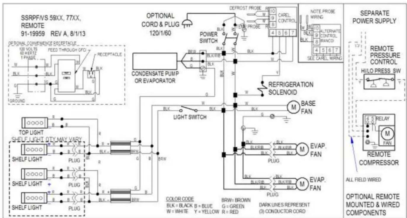
text_image
SSRPFVS 59XX, 77XX, REMOTE 91-19959 REV A, 8/1/13 OPTIONAL CONVENIENCE RECEPTACLE 120 VOLTIS 60 HERTZ 1 PHASE W BLK G GROUND FEED THROUGH GFCI W BLK G BLK G OPTIONAL CORD & PLUG 120/1/60 POWER SWITCH CONDENSATE PUMP OR EVAPORATOR DEFROST PROBE R W BLK W BLK W BLK W BLK W BLK W BLK W BLK W BLK W BLK W BLK W BLK W BLK W BLK W BLK W BLK W BLK W BLK W BLK W BLK W BLK W BLB BLKB BLKB BLKB BLKB BLKB BLKB BLKB BLKB BLKB BLKB BLKB BLKB BLKB BLKB BLKB BLKB BLKB BLKB BLKB BLKB BLKB BLKB BLKB BLKB BLKB BLKB BLKB BLKB BLKB BLKB BLKB BLKB BLKB BLKB(16) REPLACEMENT PARTS
| REFRIGERATION(SELF CONTAINED) | SSRPF3652 SSRVS3642 | SSRPF5052 SSRVS5042 | SSRPF5952 SSRVS5942 | SSRPF7752 SSRVS7742 |
| Compressor (Self Contained) | 30-18049 | 30-18052 | 30-18645 | 30-18645 |
| Condensing Unit (Self Contained) | 30-17726 | 30-17887 | 30-18215 | 30-18215 |
| Evaporator Coil | 33-13356 | 33-13357 | 33-13358 | 33-13358 |
| TXV | 32-19420 | 32-19419 | 32-19419 | 32-19416 |
| Filter Drier | 32-12626 | 32-12626 | 32-12626 | 32-12626 |
| Sight Glass | 32-54010 | 32-54010 | 32-54010 | 32-54010 |
| Evaporator Fan Motor (Self Contained) | 41-17981 | 41-19070 | 41-19070 | 41-19070 |
| Evaporator Fan Motor (Remote) | 41-11170 | 41-11170 | 41-11170 | 41-11170 |
| Evaporator Fan Blade | 72-17355 | 72-17355 | 72-17355 | 72-19832 |
| Latch Evaporator Housing to Coil | 66-13640 | 66-13640 | 66-13640 | 66-13640 |
| Pressure Control (Self Contained) | 32-51009 | 32-51009 | 32-51009 | 32-51009 |
| Temperature Control (Self Contained) | 32-19864-6 | 32-19865-6 | 32-19865-6 | 32-19865-6 |
| Temperature Control (Remote) | 32-19864-6 | 32-19864-6 | 32-19864-6 | 32-19864-6 |
| Temperature Probe | 32-19866 (2) | 32-19866 (2) | 32-19866 (2) | 32-19866 (2) |
| Solenoid Remote Refrigeraon (Remote) | 32-30141 | 32-30141 | 32-30141 | 32-30141 |
| Condensate Pan Assembly (Self Contained) | SA5302-1 | SA5302-2 | SA5302-2 | SA5302-2 |
| Condensate Pan Heater (Self Contained) | 40-19331 | 40-19392 | 40-19392 | 40-19392 |
| Condensate Pump (Remote) | 47-18980 | 47-18980 | 47-18980 | 47-18980 |
| Condensate Drain Tube | SA4490-1 | SA4490-2 | SA4490-2 | SA4490-2 |
| Condensate Drain Tube (Remote) | SA4490-3 | SA4490-3 | SA4490-3 | SA4490-3 |
| Thermometer | 32-13662 | 32-13662 | 32-13662 | 32-13662 |
| ELECTRICAL | SSRPF3652 SSRVS3642 | SSRPF5052 SSRVS5042 | SSRPF5952 SSRVS5942 | SSRPF7752 SSRVS7742 |
| Light Switch | 41-11066 | 41-11066 | 41-11066 | 41-11066 |
| Power Switch | 41-18186 | 41-18186 | 41-18186 | 41-18186 |
| Light Power Supply | 39-19039 | 39-19039 | 39-19039 | 39-19039 |
| LED Ceiling Light Strip | 42-19038-5 | 42-19038 | 42-19038-6 | 42-19038-3 |
| LED Shelf Light Strip | 42-19038-5 | 42-19038 | 42-19038-6 | 42-19038-3 |
| LED (12 Inch) Shelf Light Cord | 43-16861-3 | 43-16861-3 | 43-16861-3 | 43-16861-3 |
| LED (15 Inch) Shelf Light Cord | 43-16861-1 | 43-16861-1 | 43-16861-1 | 43-16861-1 |
| LED (18 Inch) Shelf Light Cord | 43-16861-2 | 43-16861-2 | 43-16861-2 | 43-16861-2 |
| Power Cord (Oponal) | 43-30818 | 43-17839 | 43-19090 | 43-19090 |
| Wiring Diagram (Self Contained)SSRPF 52 | 91-19828 | 91-19854 | 91-19857 | 91-19857 |
| Wiring Diagram (Remote) SSRPF 52 | 91-19955 | 91-19957 | 91-19959 | 91-19959 |
| Wiring Diagram (Self Contained)SSRVS 42 | 91-19853 | 91-19855 | 91-19858 | 91-19858 |
| Wiring Diagram (Remote) SSRVS 42 | 91-19956 | 91-19958 | 91-19960 | 91-19960 |
| SSRPF END PANELS & GLASS | SSRPF3652 | SSRPF5052 | SSRPF5952 | SSRPF7752 |
| Glass End Clear | 50-19775 | |||
| Glass End Reeve Le(Oponal) | 50-19775-1L | |||
| Glass End Reeve Right(Oponal) | 50-19775-1R | |||
| End Panel Assem. Le (Black) | 68-19348-L | |||
| End Panel Assem. Right (Black) | 68-19348-R | |||
| End Panel Assem. Le (Color needed) | 68-19348-1L | |||
| End Panel Assem. Right (Color needed) | 68-19348-1R | |||
| End Panel Assem. Le (Stainless) | SA5383-L | |||
| End Panel Assem. Right (Stainless) | SA5383-R | |||
| SSRVS END PANELS & GLASS | SSRVS3642 | SSRVS5042 | SSRVS5942 | SSRVS7742 |
| Glass End Clear | 50-19799 | |||
| Glass End Reeve Le(Oponal) | 50-19799-1L | |||
| Glass End Reeve Right(Oponal) | 50-19799-1R | |||
| End Panel Assem. Le (Black) | 68-19802-L | |||
| End Panel Assem. Right (Black) | 68-19802-R | |||
| End Panel Assem. Le (Color needed) | 68-19802-1L | |||
| End Panel Assem. Right (Color needed) | 68-19802-1R | |||
| End Panel Assem. Le (Stainless) | SA5383-1L | |||
| End Panel Assem. Right (Stainless) | SA5383-1R | |||
| SHELVING | SSRPF3652 SSRVS3642 | SSRPF5052 SSRVS5042 | SSRPF5952 SSRVS5942 | SSRPF7752 SSRVS7742 |
| Glass Shelf 12 Inch (Oponal) | 52-19937-1 | 52-19937-2 | 52-19937-3 | 52-19937-4 |
| Glass Shelf 15 Inch (Oponal) | 52-19938-1 | 52-19938-2 | 52-19938-3 | 52-19938-4 |
| Glass Shelf 18 Inch (Oponal) | 52-19939-1 | 52-19939-2 | 52-19939-3 | 52-19939-4 |
| Glass Shelf Retainer Clip (Oponal) | SA4091 | |||
| Shelf Bracket 12 Inch | 67-16038-6A | |||
| Shelf Bracket 15 Inch | 67-16038-7A | |||
| Shelf Bracket 18 Inch | 67-16038-8A | |||
| Shelf Standard SSRPF 52 | M19171 | |||
| Shelf Standard SSRVS 42 | M19238 | |||
| Shelf Retainer, Front, Clear | W11438-14 | W11438-15 | W11438-16 | W11438-17 |
| REAR DOORS SSRPF (Oponal) | SSRPF3652 | SSRPF5052 | SSRPF5952 | SSRPF7752 |
| Track, Rear Door Boom (Oponal) | 57-18628-1 | 57-18628-2 | 57-18628-3 | 57-18628-4 |
| Track, Rear Door Jamb (Oponal) | 57-18626-3 | 57-18626-3 | 57-18626-3 | 57-18626-3 |
| Track, Rear Door Top (Oponal) | 57-18627-1 | 57-18627-2 | 57-18627-3 | 57-18627-4 |
| Door, Rear Outer Solid (Black) | 53-19891-1 | 53-19891-2 | 53-19891-3 | 53-19891-4 |
| Door, Rear Inner Solid (Black) | 53-19890-1 | 53-19890-2 | 53-19890-3 | 53-19890-4 |
| Inside Track, Door Boom (Oponal) | M16519-1 | M16519-2 | M16519-3 | M16519-4 |
| Inside Track, Door Top (Oponal) | M19453-1 | M19453-2 | M19453-3 | M19453-4 |
| Inside Door, Le Sloed Blk. (Opon.) | SA5409-1 | SA5409-2 | SA5409-3 | SA5409-4 |
| Inside Door, Right Sloed Blk. (Opon.) | SA5410-1 | SA5410-2 | SA5410-3 | SA5410-4 |
| Door Catch, Outside (Oponal) | M17196-1 | M17196-1 | M17196-1 | M17196-1 |
| Door Catch, Inside (Oponal) | M17196-2 | M17196-2 | M17196-2 | M17196-2 |
| REAR DOORS SSRVS (Oponal) | SSRVS3642 | SSRVS5042 | SSRVS5942 | SSRVS7742 |
| Track, Rear Door Boom (Oponal) | 57-18628-1 | 57-18628-2 | 57-18628-3 | 57-18628-4 |
| Track, Rear Door Jamb (Oponal) | 57-18626-4 | 57-18626-4 | 57-18626-4 | 57-18626-4 |
| Track, Rear Door Top (Oponal) | 57-18627-1 | 57-18627-2 | 57-18627-3 | 57-18627-4 |
| Door, Rear Outer Solid (Black) | 53-19982-1 | 53-19982-2 | 53-19982-3 | 53-19982-4 |
| Door, Rear Inner Solid (Black) | 53-19981-1 | 53-19981-2 | 53-19981-3 | 53-19981-4 |
| Inside Track, Door Boom (Oponal) | M16519-1 | M16519-2 | M16519-3 | M16519-4 |
| Inside Track, Door Top (Oponal) | M19453-1 | M19453-2 | M19453-3 | M19453-4 |
| Inside Door, Le Sloed Blk. (Opon.) | SA5432-1 | SA5432-2 | SA5432-3 | SA5432-4 |
| Inside Door, Right Sloed Blk. (Opon.) | SA5433-1 | SA5433-2 | SA5433-3 | SA5433-4 |
| Door Catch, Outside (Oponal) | M17196-1 | M17196-1 | M17196-1 | M17196-1 |
| Door Catch, Inside (Oponal) | M17196-2 | M17196-2 | M17196-2 | M17196-2 |
| MISCELLANEOUS | SSRPF3652 SSRVS3642 | SSRPF5052 SSRVS5042 | SSRPF5952 SSRVS5942 | SSRPF7752 SSRVS7742 |
| Air Deector Front Clear | 15-19827-1 | 15-19827-2 | 15-19827-3 | 15-19827-4 |
| Security Night Cover Panel SSRPF(Oponal) | M19299-1 | M19299-2 | M19299-3 | M19299-4 |
| Security Night Cover Panel SSRVS(Oponal) | M19367-1 | M19367-2 | M19367-3 | M19367-4 |
| Security Night Cover Latch (Oponal) | 66-11727 | 66-11727 | 66-11727 | 66-11727 |