D3PDN211 - Security Camera Aigis - Free user manual and instructions
Find the device manual for free D3PDN211 Aigis in PDF.

| Product Type | Security Camera |
| Brand | Aigis |
| Model | D3PDN211 |
| Imager | 1/3" Sony Super HAD II CCD |
| Signal System | NTSC |
| Effective Pixels | 768 (H) x 494 (V) |
| Resolution | 540 TV lines |
| Minimum Illumination | 0.3 Lux (Color) / 0.008 Lux (B/W) |
| S/N Ratio | >50 dB (AGC Off) |
| Day/Night Function | True Day/Night with Mechanical IR Cut Filter |
| Lens | 2.8-11mm Auto-Iris |
| White Balance | Auto |
| Sync Mode | Internal |
| Video Output | 1.0Vp-p, 75 Ohm |
| Power Supply | 12VDC/24VAC |
| Power Consumption | <4W |
| Dimensions (Dome) | 3.75" (95mm) Diameter |
| Dimensions (Whole Unit) | 5.92" (150mm) Width x 4.3" (109mm) Height |
| Mounting | Indoor Plastic Surface Mount |
| Control Method | OSD + Dipswitch |
| Cleaning | Use a damp cloth; do not use liquid or aerosol cleaners. |
| Safety | Follow all safety instructions; do not attempt service yourself. |
| Service | Contact Aigis Mechtronics for repair authorization. |
Frequently Asked Questions - D3PDN211 Aigis
User questions about D3PDN211 Aigis
0 question about this device. Answer the ones you know or ask your own.
Ask a new question about this device
Download the instructions for your Security Camera in PDF format for free! Find your manual D3PDN211 - Aigis and take your electronic device back in hand. On this page are published all the documents necessary for the use of your device. D3PDN211 by Aigis.
USER MANUAL D3PDN211 Aigis


D3P Series
Indoor Plastic Domes

D3PCH211
D3PWD211
D3PDN211
IMPORTANT SAFEGUARDS
I. Read Instructions - All the safety and operating instructions should be read before the unit is operated.
2. Retain Instructions - The safety and operating instructions should be retained for future reference.
3. Heed Warnings - All warnings on the unit and in the operating instructions should be adhered to.
4. Follow Instructions - All operating and use instructions should be followed.
5. Cleaning - Unplug the unit from the outlet before cleaning. Do not use liquid cleaners or aerosol cleaners. Use a damp cloth for cleaning.
6. Attachments - Do not use attachments not recommended by the product manufacturer as they may cause hazards.
7. Accessories - Do not place this unit on an unstable stand, tripod, bracket, or mount. The unit may fall, causing serious injury to a person and serious damage to the unit. Use only with a stand, tripod, bracket, or mount recommended by the manufacturer, or sold with the product. Any mounting of the unit should follow the manufacturer's instructions, and should use a mounting accessory recommended by the manufacturer.
An appliance and cart combination should be moved with care. Quick stops, excessive force, and uneven surfaces may cause the appliance and cart combination to overturn.
8. Ventilation - Openings in the enclosure, if any, are provided for ventilation and to ensure reliable operation of the unit and to protect it from overheating. These openings must not be blocked or covered. This unit should not be placed in a built-in installation unless proper ventilation is provided or the manufacturer's instructions have been adhered to.
9. Power Sources - This unit should be operated only from the type of power source indicated on the marking label. If you are not sure of the type of power supply you plan to use, consult your appliance dealer or local power company. For units intended to operate from battery power, or other sources, refer to the operating instructions.
10. Grounding or Polarization - This unit may be equipped with a polarized alternating-current line plug (a plug having one blade wider than the other). This plug will fit into the power outlet only one way. This is a safety feature. If you are unable to insert the plug fully into the outlet, try reversing the plug. If the plug should still fail to fit, contact your electrician to replace your obsolete outlet. Do not defeat the safety purpose of the polarized plug.
Alternately, this unit may be equipped with a 3-wire grounding-type plug, a plug having a third (grounding) pin. This plug will only fit into a grounding-type power outlet. This is a safety feature. If you are unable to insert the plug into the outlet, contact your electrician to replace your obsolete outlet. Do not defeat the safety purpose of the grounding-type plug.
11. Power-Cord Protection - Power-supply cords should be routed so that they are not likely to be walked on or pinched by items placed upon or against them, paying particular attention to cords and plugs, convenience

receptacles, and the point where they exit from the appliance.
12. Power Lines - An outdoor system should not be located in the vicinity of overhead power lines or other electric light or power circuits, or where it can fall into such power lines or circuits. When installing an outdoor system, extreme care should be taken to keep from touching such power lines or circuits as contact with them might be fatal. U.S.A. models only - refer to the National Electrical Code Article 820 regarding installation of CATV systems.
13. Overloading - Do not overload outlets and extension cords as this can result in a risk of fire or electric shock.
14. Object and Liquid Entry - Never push objects of any kind into this unit through openings as they may touch dangerous voltage points or short-out parts that could result in a fire or electric shock. Never spill liquid of any kind on the unit.
15. Servicing - Do not attempt to service this unit yourself as opening or removing covers may expose you to dangerous voltage or other hazards. Refer all servicing to qualified service personnel.
16. Damage Requiring Service - Unplug the unit from the outlet and refer servicing to qualified service personnel under the following conditions:
a. When the power-supply cord or plug is damaged.
b. If liquid has been spilled, or objects have fallen into the unit.
c. If the unit has been exposed to rain or water.
d. If the unit does not operate normally by following the operating instructions. Adjust only those controls that are covered by the operating instructions, as an improper adjustment of other controls may result in damage and will often require extensive work by a qualified technician to restore the unit to its normal operation.
e. If the unit has been dropped or the cabinet has been damaged.
f.When the unit exhibits a distinct change in performance--this indicates a need for service.
17. Replacement Parts - When replacement parts are required, be sure the service technician has used replacement parts specified by the manufacturer or have the same characteristics as the original part. Unauthorized substitutions may result in fire, electric shock or other hazards.
18. Safety Check - Upon completion of any service or repairs to this unit, ask the service technician to perform safety checks to determine that the unit is in proper operating condition.
19. Coax Grounding - If an outside cable system is connected to the unit, be sure the cable system is grounded. U.S.A. models only--Section 810 of the National Electrical Code, ANSI/NFPA
No.70-1981, provides information with respect to proper grounding of the mount and supporting structure, grounding of the coax to a discharge unit, size of grounding conductors, location of discharge unit, connection to grounding electrodes, and requirements for the grounding electrode.
20. Lightning - For added protection of this unit during a lightning storm, or when it is left unattended and unused for long periods of time, unplug it from the wall outlet and disconnect the cable system. This will prevent damage to the unit due to lightning and power-line surges.
FCC & ICES INFORMATION
(U.S.A. and Canadian Models Only)
WARNING - This equipment has been tested and found to comply with the limits for a Class A digital device, pursuant to Part 15 of the FCC Rules and ICES-003 of Industry Canada. These limits are designed to provide reasonable protection against harmful interference when the equipment is operated in a commercial environment. This equipment generates, uses, and can radiate radio frequency energy and, if not installed and used in accordance with the instruction manual, may cause harmful interference to radio communications. Operation of this equipment in a residential area is likely to cause harmful interference in which case the user will be required to correct the interference at his own expense. Intentional or unintentional changes or modifications not expressly approved by the party responsible for compliance shall not be made. Any such changes or modifications could void the user's authority to operate the equipment.
If necessary, the user should consult the dealer or an experienced radio/television technician for corrective action. The user may find the following booklet prepared by the Federal Communications Commission helpful: "How to Identify and Resolve Radio-TV Interference Problems." This booklet is available from the U.S. Government Printing Office, Washington, DC 20402, Stock No.004-000-00345-4.
Warning: This is a Class A product. In a domestic environment, this product may cause radio interference in which case the user may be required to take adequate measures.
1. UNPACKING
Unpack carefully. This is electromechanical equipment and should be handled with care. Check to be sure that all of the following parts are included.
• Dome housing with camera and lens
• This installation manual
- Hardware Kit
- 4 x screws
- 4 x anchors
- 1 x mounting-hole template
If any item appears to have been damaged in shipment, replace it properly in its carton and notify the shipper. If any items are missing, notify Aigis Mechtronics. The shipping carton is the safest container in which the unit may be transported. Save it for possible future use.
2. MODEL NUMBERS
| Model No. | Description | Imager | Voltage | Power |
| D3PCH211 | Indoor plastic surface mount dome camera | 540TVL, Color High Resolution | 12VDC/24VAC, 60Hz | <3.5W |
| D3PWD211 | 540TVL, Wide Dynamic Range | 12VDC/24VAC, 60Hz | <3W | |
| D3PDN211 | 540TVL, True Day/Night | 12VDC/24VAC, 60Hz | <4W |
Note: similar part numbers ending in "E" do not include a BNC test loop (service connection).
3. SERVICE
If the unit ever needs repair service, the customer should contact Aigis Mechtronics for return authorization and shipping instructions.
4. INSTALLATION

ATTENTION: Installation should be performed by qualified service personnel only, in accordance with the National Electrical or applicable codes. Refer to applicable installation section.

CAUTION: These units must be properly and securely mounted to a supporting structure capable of sustaining the unit weight. Use care when selecting mounting hardware (if different than the provided fasteners) for installation. The mounting surface and the unit's weight should be carefully considered.
1.1. Surface-Mount Installation
- Remove mounting-hole template from packaging. Peel off adhesive template from wax paper backing. Stick the template to the ceiling or wall over the desired installation location.
- Drill out the mounting holes using a 7/32-in or 5.5mm drill bit. Remove the adhesive template if desired.
- Remove the mounting base of the housing by twisting counter-clockwise (see Figure 1)

Figure 1 - Remove mounting base
- Insert a plastic anchor from the hardware kit into each of the drill holes in the wall or ceiling. Ensure that the holes are drilled deep enough that the anchors can be inserted far enough to be flush with the wall or ceiling.
- Position the mounting base over the drill holes, insert all four screws from the hardware kit through the mounting holes in the base (indicated in Figure 2). Tighten the screws finger-tight until all screws are started, then tighten down all four screws. Ensure that the mounting base is securely attached and that the wall anchors are properly seated.
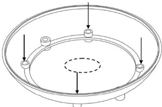
Figure 2 - Secure mounting base
-
Drill a hole in the center of the mounting holes large enough to accept the BNC and power connectors on the back of the unit.
-
Run the power and video cables into the central hole in the mounting surface.
- Reconnect the main housing to the mounting base by aligning the markings on the side of each component as shown in Figure 3. Twist the main housing clockwise relative to mounting base.

Figure 3 - Align the markings to attach the dome to the base
- Remove the dome cover from the camera base by lifting the dome cover at the tab indicated in Figure 4, or by inserting a flathead screwdriver into the tab at an upward angle, then gently turning the screwdriver 90° in the slot.
![graph TD A["目"] --> B["Rectangular Structure"] B --> C["Horizontal Section"] C --> D["Vertical Section"] D --> E["Horizontal Section"] E --> F["Vertical Section"] F --> G["Horizontal Section"] G --> H["Vertical Section"] H --> I["Horizontal Section"] I --> J["Vertical Section"]](/content/2026/06/1220958/images/6a92a3ee8348c245da9d7633511e8b5f163646ad86763e468156aeccbec14a2d.jpg)
Figure 4 - Insert flathead screwdriver and twist
-
Set the dome cover aside. Loosen the thumbnails to orient the camera bracket to obtain the desired field of view (see Figure 5).
-
Plug the test monitor into the BNC Test Monitor Jack shown in Figure 5. Adjust the Zoom and Focus settings as desired.

Figure 5 - Adjust bracket, focus and zoom
- Reinstall the dome cover onto the housing base by aligning the notch in the dome cover with the alignment tab as shown in Figure 5, then pressing down until the cover snaps into place. Ensure that the cover is properly seated.
- Twist the bubble relative to the dome cover until the cutout in the covert liner is pointed in the same direction as the camera.
- Remove the protective film from the dome bubble to complete the installation.
D3PWD211 - Wide Dynamic Range Camera Settings & Functions
The directional pad (See Figure 6) is located in the camera base next to the 3-axis bracket. Press the center button of directional pad to access the camera's On Screen Display (OSD) menu and to step back one screen. Press up or down to navigate between settings, press left or right to change values or enter a sub-menu.
Figure 6

| Setting Name | Setting Values | Default Setting | Description |
| Language...... | English, Chinese...... | English...... | Select the language to be displayed on-screen |
| WDR Setup...... | Auto, High, Low, Custom... | Auto...... | Select a preset level, or custom to manually set Bias and Limit |
| Limit | |||
| Basic Setup...... | Press the center button to enter sublevel | ||
| Video Signal...... | Press the center button to enter sublevel | ||
| Video Format...... | NTSC, PAL...... | NTSC...... | Select the appropriate type of electrical system |
| Video Level...... | 80 min 150 max...... | 100...... | Increases / decreases the sensitivity of the imager |
| Mirror...... | Off / Hor. / Vert. / Both... | Off...... | Press left or right to select the type of mirror |
| Image Adjust...... | Press the center button to enter sublevel | ||
| Gamma Mode...adjust | Auto / Manual...... | Auto...... | Press the center button when Manual is highlighted to |
| Gamma......darkest) | 25 min to 100 max...... | 45...... | Controls the overall brightness of the image (100 = |
| Sharpness......apparent | -8 min to + 8 max...... | 0...... | Softens or sharpens the image. Noise may become |
| Saturation......image | -8 min to + 8 max...... | 0...... | Lower value reduces the color level (saturation) of the |
| Title...... | Press the center button to enter sublevel | ||
| Display...... | Off / On...... | Off...... | On setting causes title to be overlaid over image |
| Title...... | 8 alphanumericcs...... | Camera_1...... | Press the center button when “Title” is highlighted. Cursor will move over the first letter. Left / right button changes letter, center button moves to next letter. Up to 8 letters and/or numbers can be entered. |
| Position...... | UL/UC/UR/LL/LR...... | Up-Left...... | Select upper-right, upper-center, etc. 5 Presets available |
| Lens Select......camera | DC / Video / Manual...... | DC...... | Match this setting to the type of lens attached to the |
| Sync...... | Int 1 / Int 2 / LL...... | Int 1...... | Determines the type of synchronization to be used. Press the center button when LL (Line Lock) is highlighted to manually select a phase value from zero to 624. This would permit you to setup all cameras on the same system with the same parameter to eliminate rolling which switching video sources. INT 1 is locked to the internal clock at 59.94 Hz. INT 2 is locked to the internal clock at 60.01 Hz. |
| Exposure...... | Press the center button to enter sublevel | ||
| White Balance.... | Multiple – see below...... | ATW...... | Multiple selections available, described below |
| ATW...... | Continuously adjusts the white balance of the video automatically | ||
| ATW Extend...... | Camera performs like in ATW mode, but desaturation begins when the calculated color temperature goes below 2800K or above 7500K (for sodium lighting). | ||
D3PWD211 - Wide Dynamic Range Camera Settings & Functions, Cont'd
| Setting Name | Setting Values | Default Setting | Description |
| AWG...... | Manually set the white level by pointing the camera at a white surface (wall, paper) and selecting the Save option. The color temperature will be written to ROM (memory) and will remain constant until the user saves over that value. | ||
| Manual...... | Allows the user to adjust the red/blue color composition of the image. Move the red/blue sliders left and right to increase or decrease the red or blue elements in the image. Red default = -18, Blue default = 13. | ||
| AE PREFs...... | Highlight / Shadow...... | Highlight...... | Optimize the exposure when high dynamic range light is detected. |
| Highlight...... | Optimizes scene for highlights. Bright parts of the image are most visible, and dark parts of the image appear darkest. | ||
| Shadow...... | Optimizes scene for shadows. Dark parts of the image are most visible. Light parts of the image may saturate. | ||
| Gain Setup...... | High / Med / Low / Cust... | Medium...... | Higher Gain values provide brighter images. Custom details below. |
| Custom...... | Manually set Bias (increase or decrease in brightness) and Limit (bias only increases to a certain value). | ||
| Low Light...... | Gain / Slow Shutter...... | Slow Shutter... | Sets how the camera reacts to low light conditions. Details below. |
| Gain Mode...... | Gain increases as light decreases up to the value defined by Limit in the Gain Setup submenu. The dynamic range is not decreased as gain increases, the signal and noise are both amplified. The higher the gain, the noisier the image. In Gain Mode there is no motion blurring. | ||
| Slow Shutter Mode...... | The camera uses a combination of increasing Gain and slowing the shutter speed to compensate for decreased light levels. Set the Shutter Speed limit to x2, x4, x8, x16, x32. “x2” means the shutter speed is half the normal rate. For example, if the shutter speed is 1/60, the x2 setting will reduce the shutter speed to 1/30. Slowing the shutter speed can improve the image, but motion blurring can occur. | ||
| Advanced Setup | |||
| Zone Exposure...... | Many installations include multiple light sources or unusual lighting conditions. The camera can uses meter zones to manage the image. A light or color reference can be set which forces the camera to adjust the rest of the image based on that reference. | ||
| Meter Mode...... | Foreground / Background...... | Selects either the Foreground or Background for metering exposure, white balance, and dynamic range. In foreground mode, the camera analyzes both brightness and color elements in the meter zone, then it adjust these elements throughout the entire image. In background mode, the camera analyzes the light levels in the meter zone, then it enhances the detail for backlight objects that would otherwise appear as silhouettes. | |
D3PWD211 - Wide Dynamic Range Camera Settings & Functions, Cont'd
| Setting Name Setting Values | Default Setting | Description | |
| F.G. Presets..... | Multiple..... | Full Screen..... | Select Full Screen, Most_Screen, Center Spot, or Lower 1/3 |
| F.G. Zones..... | Enable and modify Foreground Zones 1-4 | ||
| Enable Zones. | Only 1/2/3/4..... | Only 1..... | Select which Foreground Zone to enable (only 1 active at a time) |
| Adjust Zones..... | See below for adjustment procedures. | ||
| B.G. Zones..... | Enable and modify Background Zones 1-4 | ||
| Enable Zones. | Only 1/2/3/4..... | Only 1..... | Select which Background Zone to enable (only 1 active at a time) |
| Adjust Zones..... | See below for adjustment procedures. | ||
| Zone Adjustment Procedures..... | Highlight the enabled zone and press the center key to adjust it. When the zone is White it can be moved around the image. Press the center button to turn the zone Green. When it is Green the zone can only be expanded. Press the center button again to turn the zone Red. When it is Red the zone can only be shrunk. Press the center button again to return to White. Press and hold the center button for 2 seconds to return to the previous menu. Note: Zone 4 will appear invisible at first because it takes up the whole screen. Press the center button twice to turn it Red, at which point the zone can be shrunk back into view. | ||
| Privacy Mask Setup..... | Block out a portion (or multiple portions) of the output image. Press center button to enter submenu. | ||
| Privacy Mask..... | On / Off.....Off..... | Select On and press center button to adjust masks 1-6 | |
| Masks 1 through 6..... | To enable a mask and modify it, highlight the desired mask and press Right to adjust the setting to On. Press the center button once to begin modifying it. A gray area will appear on the screen (on initial setup the box is small. While the box is gray it can be moved around the screen. Press the center button causes the gray area to turn blue, at which point the size of the mask zone can be adjusted. Press left, right, up, and down to create the desired mask zone. Pressing the center button again will turn the zone gray. Move the zone if needed, or press and hold the center button to return to the previous menu. Up to 6 mask zones can be enabled at the same time. | ||
| Mask Color..... | Red / White / Black..... | Red..... | Select the color of the mask zone as it will appear on the video. |
| Save/Default..... | Save / Default..... | Save..... | Select Save to write the current settings to memory, or Default to reset the settings to the factory default. |
| Exit Menu..... | Removes the On Screen Display from the video output. | ||

| Model No. | D3PDN211 | D3CH211 | D3PWD211 |
| Description | True Day/Night Camera | Color Hi-Res Camera | Wide Dynamic Range Camera |
| Imager | 1/3" SonyTM Super HAD II CCD | 1/3" SonyTM CCD 1/3" PiximTM DPS Sensor | |
| Signal System NTSC | |||
| Effective Pixels | 768 (H) x 494 (V) | 720 (H) x 480 (V) | |
| Resolution 540TV | |||
| Minimum Illumination | 0.3Lux/F1.2 (Color)0.008Lux/F1.2 (B/W) | 0.1Lux/F1.2 | 0.5Lux/F1.2; 0.08Lux/F1.2 (Slow Shutter) |
| S/N Ratio | >50dB (AGC Off) | >50dB | >50dB |
| Wide Dynamic Range - | 101dB Typical, 120dB Max | ||
| Control Method - OSD + Dipswitch | |||
| Privacy Masking | - | 12 zones (optional) | |
| Day/Night Function | Mechanical IR Cut Filter | - | Digital D/N |
| Lens | 2.8-11mm Auto-Iris | ||
| White Balance | Auto | AWB/ATW/Manual Selectable | |
| AWB Range | - | ATW 2,000K to 11,000K | |
| BLC | Auto | - | |
| AGC | Auto | Adjustable | |
| Gamma Correction | - | - | Adjustable |
| Sync Mode | Internal | Internal / Line Lock | |
| Video Output | 1.0Vp-p, 75 Ohm | 0.8-1.5Vp-p adjustable, 75 Ohm | |
| Power Supply | 12VDC/24VAC | ||
| Power Consumption | <4W | <3.5W | <3W |
| Dimensions (Dome) | 3.75" (95mm) Diameter | ||
| Dimensions (Whole Unit) | 5.92" (150mm) Width, 4.3" (109mm) Height | ||
Note: Similar part numbers ending in "E" have the same specifications but do not include a BNC test loop (service connection). For example, D3CH211E has the same specifications as D3CH211 except for the test loop feature.
This page intentionally left blank

mechtronics
Now Part of Linear ® Building On Innovation.
1950 Camino Vida Roble, Suite 150
Carlsbad, CA 92008
Tel: 760.438.7000 800.421.1587
www.aigismech.com • www.linearcorp.com
Copyright © 2011 Linear LLC
100 0255 003 AIG 08/11
Printed in the U.S.A.
Brand : Aigis
Model : D3PDN211
Category : Security Camera