
D5WD211P-W - Security Camera Aigis - Free user manual and instructions
Find the device manual for free D5WD211P-W Aigis in PDF.

| Product Type | Indoor Security Camera |
| Model Number | D5WD211P-W |
| Brand | Aigis |
| Imager | 1/3" DPS (Digital Pixel System), 540 TVL |
| Power Supply | 24VAC, 4.5W |
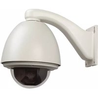
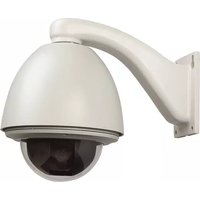
| Installation Type | In-ceiling recess, pendant pole, or wall mount |
| Camera Adjustments | Manual pan, tilt, and rotation (360°) |
| Dome Diameter | Approximately 5.75 inches (146 mm) |
| UTP Option | Factory-installed unshielded twisted pair transmitter (RJ45) |
| Remote Video Setup | Using second coaxial cable and monitor |
| Weight (estimated) | Approximately 1.5 lbs (0.68 kg) |
| Cleaning Instructions | Unplug before cleaning; use damp cloth only; no liquid or aerosol cleaners |
| Safety Precautions | Read all instructions; avoid water, overloaded outlets; polarized plug; grounding |
| Servicing | Refer to qualified personnel; do not open covers; use manufacturer-specified parts |
| Mounting Hardware | Ceiling cutout template; conduit nuts; wall arm kit for wall mount versions |
| FCC Compliance | Class A digital device; may cause interference in residential areas |
Frequently Asked Questions - D5WD211P-W Aigis
User questions about D5WD211P-W Aigis
0 question about this device. Answer the ones you know or ask your own.
Ask a new question about this device
Download the instructions for your Security Camera in PDF format for free! Find your manual D5WD211P-W - Aigis and take your electronic device back in hand. On this page are published all the documents necessary for the use of your device. D5WD211P-W by Aigis.
USER MANUAL D5WD211P-W Aigis
natural_image
Technical line drawing of a mechanical assembly with no visible text or symbols

natural_image
Technical line drawing of a mechanical assembly with no visible text or symbols
natural_image
Pure technical diagram of a mechanical component with no text, numbers, or symbols5-INCH
INTEGRATED DOME PACKAGE(S)

D5 SERIES
INSTALLATION AND OPERATING INSTRUCTIONS
WWW.AIGISMECH.COM
IMPORTANT SAFEGUARDS
I. Read Instructions - All the safety and operating instructions should be read before the unit is operated.
2. Retain Instructions - The safety and operating instructions should be retained for future reference.
3. Heed Warnings - All warnings on the unit and in the operating instructions should be adhered to.
4. Follow Instructions - All operating and use instructions should be followed.
5. Cleaning - Unplug the unit from the outlet before cleaning. Do not use liquid cleaners or aerosol cleaners. Use a damp cloth for cleaning.
6. Attachments - Do not use attachments not recommended by the product manufacturer as they may cause hazards.
7. Water and Moisture - Do not use this unit near water - for example, in a wet basement, near a swimming pool, in an unprotected outdoor installation, or in any area which is classified as a wet location.
8. Accessories - Do not place this unit on an unstable stand, tripod, 18. bracket, or mount. The unit may fall, causing serious injury to a person and serious damage to the unit. Use only with a stand, tripod, bracket, or mount recommended by the manufacturer or sold with the product. Any mounting of the unit should follow the manufacturer's instructions and should use a mounting accessory recommended by the manufacturer.

An appliance and cart combination should be moved with care. Quick stops, excessive force, and uneven surfaces may cause the20. appliance and cart combination to overturn.
- Ventilation - Openings in the enclosure, if any, are provided for ventilation, to ensure reliable operation of the unit, and to protect it from overheating. These openings must not be blocked or covered. This unit should not be placed in a built-in installation unless proper ventilation is provided or the manufacturer's instructions have been adhered to.
- Power Sources - This unit should be operated only from the type of power source indicated on the marking label. If you are not sure of the type of power supply you plan to use, consult your dealer or local power company. For units intended to operate from battery power or other sources, refer to the operating instructions. This equipment is to be isolated from the mains supply by a limited power source as specified in EN60950:1992 Clause 2.11.
- Grounding or Polarization - This unit may be equipped with a polarized alternating-current line plug (a plug having one blade wider than the other). This plug will fit into the power outlet only one way. This is a safety feature. If you are unable to insert the plug fully into the outlet, try reversing the plug. If the plug should still fail to fit, contact your electrician to replace your obsolete outlet. Do not defeat the safety purpose of the polarized plug.
Alternately, this unit may be equipped with a 3-wire grounding-type plug, a plug having a third (grounding) pin. This plug will only fit into a grounding-type power outlet. This is a safety feature. If you are unable to insert the plug into the outlet, contact your electrician to replace your obsolete outlet. Do not defeat the safety purpose of the grounding-type plug.
- Power Cord Protection - Power supply cords should be routed so that they are not likely to be walked on or pinched by items placed upon or against them, paying particular attention to cords and plugs, convenience receptacles, and the point where they exit from the appliance.
- Power Lines - An outdoor system should not be located in the vicinity of overhead power lines or other electric light or power circuits or where it can fall into such power lines or circuits. When installing an outdoor system, extreme care should be taken to keep from touching such power lines or circuits as contact with them might be fatal. U.S.A. models only - refer to the National Electrical Code Article 820V regarding installation of CATV systems.
- Overloading - Do not overload outlets and extension cords as this can result in a risk of fire or electric shock.
-
Object and Liquid Entry - Never push objects of any kind into this unit through openings, as they may touch dangerous voltage points or short out parts that could result in a fire or electric shock. Never spill liquid of any kind on the unit.
-
Servicing - Do not attempt to service this unit yourself as opening or removing covers may expose you to dangerous voltage or other hazards. Refer all servicing to qualified service personnel.
- Damage Requiring Service - Unplug the unit from the outlet and refer servicing to qualified service personnel under the following conditions:
a. When the power supply cord or plug is damaged.
b. If liquid has been spilled or objects have fallen into the unit.
c. If the unit has been exposed to water and/or inclement weather (rain, snow, etc.).
d. If the unit does not operate normally by following the operating instructions. Adjust only those controls that are covered by the operating instructions, as an improper adjustment of other controls may result in damage and will often require extensive work by a qualified technician to restore the unit to its normal operation.
e. If the unit has been dropped or the cabinet has been damaged.
When the unit exhibits a distinct change in performance—this indicates a need for service.
- Replacement Parts - When replacement parts are required, be sure the service technician has used replacement parts specified by the manufacturer or have the same characteristics as the original part. Unauthorized substitutions may result in fire, electric shock, or other hazards.
- Safety Check - Upon completion of any service or repairs to this unit, ask the service technician to perform safety checks to determine that the unit is in proper operating condition.
Coax Grounding - If an outside cable system is connected to the unit, be sure the cable system is grounded. U.S.A. models only—Section 810 of the National Electrical Code, ANSI/NFPA No.70-1981, provides information with respect to proper grounding of the mount and supporting structure, grounding of the coax to a discharge unit, size of grounding conductors, location of discharge unit, connection to grounding electrodes, and requirements for the grounding electrode.
21. Lightning - For added protection of this unit during a lightning storm, or when it is left unattended and unused for long periods of time, the unplug it from the wall outlet and disconnect the cable system. This will prevent damage to the unit due to lightning and power-line surges.
FCC & ICES INFORMATION
(U.S.A.andCanadianModelsOnly)
WARNING - This equipment has been tested and found to comply with the limits for a Class A digital device, pursuant to Part 15 of the FCC Rules and ICES-003 of Industry Canada. These limits are designed to provide reasonable protection against harmful interference when the equipment is operated in a commercial environment. This equipment generates, uses, and radiates radio frequency energy and, if not installed and used in accordance with the instruction manual, may cause harmful interference to radio communications. Operation of this equipment in a residential area is likely to cause harmful interference in which case the user will be required to correct the interference at his own expense. Intentional or unintentional changes or modifications not expressly approved by the party responsible for compliance shall not be made. Any such changes or modifications could void the user's authority to operate the equipment.
If necessary, the user should consult the dealer or an experienced radio/television technician for corrective action. The user may find the following booklet prepared by the Federal Communications Commission helpful: "How to Identify and Resolve Radio-TV Interference Problems." This booklet is available from the U.S. Government Printing Office, Washington, DC 20402, Stock No.004-000-00345-4.
0Warning
This is A class A product. In a domestic environment, this product may cause radio interference in which case the user may Be required To take adequate measures.
SECURITY

CAUTION
RISK OF ELECTRIC SHOCK. DO NOT OPEN!

CAUTION: TO REDUCE THE RISK OF ELECTRICAL SHOCK, DO NOT OPEN COVERS. NO USER SERVICEABLE PARTS INSIDE. REFER SERVICING TO QUALIFIED SERVICE PERSONNEL.
This label may appear on the bottom of the unit due to limitations.
SECURITE

ATTENTION
RISQUE DI OCUTION. NE PAS OUVRIR

The lightning flash with an arrowhead symbol within an equilateral triangle is intended to alert the user to the presence of uninsulated "dangerous voltage" within the product's enclosure that may be of sufficient magnitude to constitute a risk of electric shock to persons.

The exclamation point within an equilateral triangle is intended to alert the user to presence of important operating and maintenance (servicing) instructions in the literature accompanying the appliance.

Attention: Installation should be performed by qualified service personnel only in accordance with the National Electrical Code or applicable local codes.

This equipment is to be isolated from the mains supply by a limited power source as specified in EN60950:1992 Clause 2.11.
Unpack carefully. This is electromechanical equipment and should be handled with care.
Check to be sure that all of the following parts are included:
• Dome housing with camera and lens.
(Pendant Versions include: )
I- dome top cover
2- conduit nuts
(Wall Mount Versions include:)
I- dome top cover
2- conduit nuts
I- wall arm and hardware kit
If an item appears to have been damaged in shipment, replace it properly in its carton and notify the shipper. If any items are missing, notify Aigis Mechtronics.
The shipping carton is the safest container in which the unit may be transported. Save it for possible future use.
2 MODEL NUMBERS
| Model No. | Description Imager Voltage | Power | ||
| D5CH211R Indoor, in-ceiling recess mount 1/3" | Sony Color Hi-Res, 540 TVL 24VAC | .8 W | ||
| D5CH211P Indoor, pendant pole mount 1/3" | Sony Color Hi-Res, 540 TVL 24VAC 1.8 | W | ||
| D5CH211W Indoor, pendant wall mount 1/3" | Sony Color Hi-Res, 540 TVL 24VAC 1.8 | W | ||
| D5WD211R Indoor, in-ceiling recess mount 1/3" | DPS (Digital Pixel System), 540 TVL 24VAC 4.5 W | |||
| D5WD211P Indoor, pendant pole mount 1/3" | DPS (Digital Pixel System), 540 TVL 24VAC 4.5 W | |||
| D5WD211W Indoor, pendant wall mount 1/3" | DPS (Digital Pixel System), 540 TVL 24VAC 4.5 W | |||
| Note:1.) All models available in black or white, add -B or -W to end of model number.2.) UTP versions will be indicated by -UW or -UB at the end of the model #. Refer to Section 5 for UTP specific information. | ||||
3 SERVICE
If the unit ever needs repair service, the customer should contact Aigis Mechtronics for return authorization and shipping instructions.
4 INSTALLATION

ATTENTION: Installation should be performed by qualified service personnel only, in accordance with the National Electrical Code or applicable local codes. Refer to applicable installation section.
4.1 In-ceiling Model (D5 xx xxx R)

CAUTION: These units must be properly and securely mounted to a supporting structure capable of sustaining the unit weight. Use care when selecting mounting hardware (not supplied) for installation, the mounting surface and unit's weight should be carefully considered.
- Use 2 pencils or a pencil and nail with provided template to cut a 146 mm (5.75-inch) diameter hole in the ceiling where required. The template is found in of the shipping carton, labeled "Install Tool". Connect low voltage power and video (see Figure 1).
NOTE: Power and video can be connected before or after the unit is mounted into the ceiling:
a. Connect the line and neutral wires to the terminal block in the back of the housing.
b. Route and connect video cable to the BNC connector also located on the back of the housing.

Figure 1 Ceiling Mount Power & Video Connections
- Install the base assembly box into the precut hole until the base's flange hits the ceiling. Tighten the three screws that serve to lower the mounting clamps to grab on to the ceiling. Be sure the clamps are secure against the ceiling (see Figure 2).
- Adjust the camera module for proper viewing angle. See Section 4.3 for more information on camera adjustments.
- Once the camera is positioned properly, install the black inner liner and align the viewing slot with the camera and lens (see Figure 2).
- When the inner liner is properly located, install the dome and trim ring by lining up the colored dots and rotating clockwise until it is locked in place.

Figure 2 In-ceiling Installation
4.2 Pendant Model (D5 xx xxx P or W)
The pendant mount version of the D5 Series can be mounted to a wall or conduit/pipe.
4.2.1 Conduit/Pipe Mounting
- When pendant mounting to a vertical conduit, route power/video cables through your mounted conduit. Screw one of conduit nuts (see step 3), onto the conduit, then route these cables through the removable pendant cap.
- Attach the 3/4-inch (NPT) conduit to the top of the pendant cap using two conduit nuts as shown in Figure 3. Conduit is not supplied.

Figure 3 Pendant Pipe Mount Installation
- Route power/video cables to the terminal block and BNC connector located on the back of the housing and make proper connections. See Figure 1.
- Attach base camera/lens unit to pendant cap by lining up and joining the cap's four studs to the slots located on the back of the base unit. Twist the housing to lock it into place (see Figure 3).
- Adjust the camera module for proper viewing angle. See Section 4.3 for more information on camera adjustments.
- Once the camera is positioned properly, install the black inner liner and align the viewing slot with the camera and lens (see Figure 2).
- When the inner liner is properly located, install the dome and trim ring by lining up the colored dots and rotating clockwise until it is locked in place.
4.2.2 Wall Mounting
I. Wall mount the unit using the D5MT-B (black) or -W (white) wall mount (provided with the D5xxxxxW series or can be purchased separately).
2. When wall mounting, route power/video cables through the wall mount. Securely mount the bracket in the desired location using four fasteners (see Figure 4) that are appropriate for the type of wall.
3. Feed power/video cables through removable pendant cap and attach cap to mount using the supplied conduit nut (see Figure 4).
4. Route power/video cables to the terminal block and BNC connector located on the back of the housing and make proper connections (see Figure I).
5. Attach base camera/lens unit to pendant cap by lining up and joining the cap's four studs to the slots located on the back of the base unit. Twist the housing to lock it into place (see Figure 3).
6. Adjust the camera module for proper viewing angle. See Section 4.3 for more information on camera adjustments.
7. Once the camera is positioned properly, install the black inner liner and align the viewing slot with the camera and lens (see Figure 2).
8. When the inner liner is properly located, install the dome and trim ring by lining up the colored dots and rotating clockwise until it is locked in place.

Figure 4 Pendant Wall Mount Installation
4.3 Camera Adjustments
I. The camera can manually pan, tilt, or rotate 360 degrees. See Figure(s) 5a and 5b for a diagram of these adjustments.


Figure 5a Camera Position Adjustments

natural_image
Technical line drawing of a mechanical device with a 90-degree tilt indicator (no text or symbols on the diagram itself)
natural_image
Technical line drawing of a mechanical device with a labeled component (no text or symbols on the diagram itself)Camera shown is Color High Resolution WDR camera is similar in Tilt adjustments.
Figure 5b Camera Tilt Adjustments
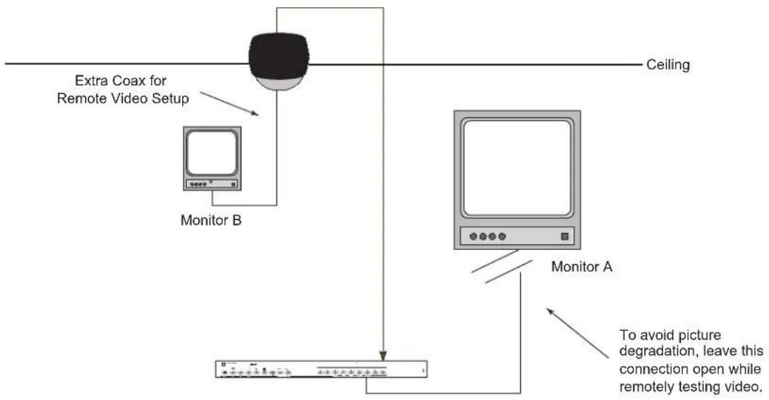
4.4 Remote Video Setup
A second coaxial cable is included to allow the installer to set up the video at the camera site using a small spare monitor. Refer to the following steps for this procedure.
- After the power and video connections are made to the camera and the dome is mounted correctly, connect the setup coax cable with BNC located next to the camera/lens module to the remote monitor. See Figure 6a for an example of a simple setup configuration.
flowchart
graph TD
    A["Monitor A"] --> B["Monitor B"]
    B --> C["Extra Coax for Remote Video Setup"]
    C --> D["Ceiling"]
    D --> E["To avoid picture degradation, leave this connection open while remotely testing video."]
Figure 6a Example of Setup Configuration Using Remote Monitor
- Disconnect the video connection at the main monitor to avoid double termination and possible picture degradation.
- Adjust the camera angle to obtain the required view.
- Disconnect the setup coax and connect the coax video cable to the main monitor at the viewing station. See Figure 6b for an example of a permanent configuration.

flowchart
graph TD
    A["Ceiling"] --> B["Monitor A"]
    B --> C["Monitor A"]
    style A fill:#f9f,stroke:#333
    style B fill:#ccf,stroke:#333
    note right of B: Make permanent connection to display monitor after setup is complete
Figure 6b Example of Permanent Configuration
5 NETWORK UTP OPTION
Factory installed unshielded twisted pair transmitter requires no adjustments to be made during installation.
- Ensure that the pin designation used in the Aigis UTP product (see below) corresponds to that of the receiver. Refer to the receiver manufacturer's Operating Mannal for information on max wire lengths.
| PinNumberColorUtilization | ||
| 1 Orange / | White Video Signal | |
| 2 Orange | Video Ground | |
| 3 Green / | White Data | |
| 4 Blue 24VAC | ||
| 5 Blue / | White 24VAC | |
| 6 | Green | Data |
| 7 Brown / | White 24VAC | |
| 8 | Brown | 24VAC |

RJ45 Jack
Figure 7 UTP Pinout Designation
- Run network cable between the receiver and the Aigis UTP product. Note that the Power and Video leads have been replaced with an RJ45 jack. Plug in the network cable and power the unit before connecting the test monitor.
DIMENSIONAL OUTLINES


mechtronics
©2009 Aigis Mechtronics
1124 Louise Road, Winston-Salem, NC 27107-5450
Tel: 336.785.7740 Fax: 336.785.7744
Data subject to change without notice
AIG 100 0247 001 09/09
Printed in U.S.A.
- 5-INCH
- INTEGRATED DOME PACKAGE(S)
- IMPORTANT SAFEGUARDS
- FCC & ICES INFORMATION
- (U.S.A.andCanadianModelsOnly)
- 0Warning
- SECURITY
- CAUTION
- SECURITE
- ATTENTION
- MODEL NUMBERS
- SERVICE
- INSTALLATION
- In-ceiling Model (D5 xx xxx R)
- Pendant Model (D5 xx xxx P or W)
- Conduit/Pipe Mounting
- Wall Mounting
- Camera Adjustments
- Remote Video Setup
- NETWORK UTP OPTION
Brand : Aigis
Model : D5WD211P-W
Category : Security Camera