JRN062-102D20TL5 - Inverter Geist - Free user manual and instructions
Find the device manual for free JRN062-102D20TL5 Geist in PDF.

User questions about JRN062-102D20TL5 Geist
0 question about this device. Answer the ones you know or ask your own.
Ask a new question about this device
Download the instructions for your Inverter in PDF format for free! Find your manual JRN062-102D20TL5 - Geist and take your electronic device back in hand. On this page are published all the documents necessary for the use of your device. JRN062-102D20TL5 by Geist.
USER MANUAL JRN062-102D20TL5 Geist
natural_image
Orange hexagonal logo with abstract geometric shapes (no text or symbols)GEIST
POWER
Instruction Manual
Rack PDU
J, VHV, and MJ Series
Table of Contents
Introduction 5
Welcome....5
About this Manual 8
Revision History....8
Organization of the Manual....9
Audience Profile....9
On-line Documentation....9
Reporting Document Errors....9
Conventions....10
Software 10
Hardware 10
Safety 12
Figures 13
Tables 13
Chapter 1 - Product Specifications 14
Overview.... 14
Environmental.... 14
Temperature 14
Humidity 14
Elevation 14
Electrical.... 15
Receptacle Ratings 15
Regulatory Compliance.... 15
Underwriters Laboratories (UL) 15
CE 15
Federal Communications Commission (FCC) 16
RoHS/WEEE 17
Chapter 2 - Installation 18
Installation.... 18
Mounting 19
Chapter 3 - Setup 28
Optional Local Monitoring.... 28
Power Meter 28
Current Meter 29
Chapter 4 - Final Checkout 30
Final Checkout.... 30
Technical Support 30
Service and Maintenance 30
More Technical Support....30
Product-Specific Safety Notices.... 31
General Safety 31
Live Circuits Safety 31
Equipment Grounding 31
Electrostatic Discharge 32
Explosive Environment 32
Servicing and Adjustments 32
Repairs and Modifications 32
Introduction
Welcome
Notice to Users
Geist, a division of Vertiv, Inc., reserves the right to make changes to this document without notice to any user or reseller of this product. Geist, a division of Vertiv, Inc., also reserves the right to substitute or terminate distribution of this document, with no obligation to notify any person or party of such substitutions or terminations.
Copyrights
© 2018 - Geist, a division of Vertiv, Inc. All Rights Reserved.
Trademarks
All Trademarks contained herein are registered to Geist, a division of Vertiv, Inc.
Use and Disclosure Restrictions
The software and documentation contained in this publication are copyrighted materials.
Recovery Act Buy American
Geist products adhere to the Buy American provisions of the American Recovery and Reinvestment Act of 2009 (Recovery Act). All Geist goods manufactured in our Lincoln, Nebraska, plant have undergone substantial transformation during production.
Trade Agreements Act (TAA)
Geist goods manufactured in our Lincoln, Nebraska, plant have undergone substantial transformation during production. These Geist products adhere to U.S. Trade Agreements Act and can be supplied for GSA Schedules and other government contracts.
Geist Policy on Conflict Minerals
This document details Geist's corporate policy regarding the use of conflict minerals. The policy expressed in this document should be considered to cover the Geist and Geist Europe divisions of Vertiv Inc.
Section 1502 of the Dodd-Frank Act which was passed by the US Congress in 2010 requires certain companies to annually disclose their use of conflict minerals. Conflict minerals covered under this act include tantalum, tin, tungsten, and gold.
Although Geist is not directly subjected to the requirements of the Dodd-Frank Act, Geist recognizes that all companies within the electronics manufacturing industry supply chain are impacted by this legislation. Geist supports the intent of the law, which is the reduction of violence within the Democratic Republic of the Congo and will take several actions to both advance the goals of the Dodd-Frank Act and to provide exceptional support to our customers.
- Geist will work with our direct suppliers to identify purchased components and materials that contain tin, tantalum, tungsten or gold.
- Geist will work with our direct suppliers to trace sources of any tin, tantalum, tungsten or gold used in our products back to the smelter.
- Geist will document our efforts to trace tin, tantalum, tungsten, and gold minerals back to the smelter and will accurately report the results to our customers.
- Geist will continue to monitor industry progress in identifying conflict-free smelters and will adjust corporate policy as the electronics supply chain becomes more fully documented.
Geist will not require that our direct suppliers source only conflict-free minerals until an adequate number of smelters has been reliably identified and audited by The Electronic Industry Citizenship Coalition (EICC) and the Global e-Sustainability Initiative (GeSI) to service the electronic industry supply chain. Mandating a conflict-free supply chain before an adequate number of smelters has been identified will prohibit the use of all tin, tantalum, tungsten, and gold originating in the Democratic Republic of the Congo and surrounding countries. This prohibition would cut off the sole income source for many artisanal miners within the region and may result in increased violence within the Democratic Republic of the Congo in direct opposition to the goals of the Dodd-Frank Act. Geist will work continuously with our direct suppliers in order to annually increase the percentage of documented conflict-free minerals that are used in our products until all products can be certified as conflict-free.
WEEE Declaration
Geist Europe is obligated to finance the cost of the collection, treatment, recovery and environmentally sound disposal of all products sold by Geist Europe into the UK market this includes:
- New WEEE (displaying ‘the crossed out wheeled bin symbol’) that Geist Europe has placed onto the market after the 13th August 2005; and
- Historic WEEE (not displaying ‘the crossed out wheeled bin symbol’), when Geist Europe is supplying new WEEE that is intended to replace the historic WEEE and is of equivalent type or fulfills the same function even if the historic WEEE was manufactured by a third party.
Please contact Geist Europe on 01823 275100 for further details or to arrange collection. (UK Only)
Document Usage
All reasonable efforts have been made to assure the accuracy of this document from any technical or typographical errors or omissions. Geist, a division of Vertiv, Inc., and its affiliates disclaim responsibility for any labor, materials, or costs incurred as a result of usage of this document. Nor shall Geist, a division of Vertiv, Inc., and its affiliates be liable for any damages, inclusive of loss of profits or data, arising from the use of or in connection with this document.
Geist, a division of Vertiv, Inc., reserves the right to make changes to this document without notice to any user or reseller of this product. Geist, a division of Vertiv, Inc., also reserves the right to substitute or terminate distribution of this document, with no obligation to notify any person or party of such substitutions or terminations.
About this Manual
This document provides an overview of Geist product(s), the major topics covered include:
• Copyright, Trademarks, and Disclosure Restrictions.
- Instructions for installing, powering and using the equipment.
• Information that will aid in managing and maintaining the equipment.
Revision History
| Revision | Date | Notes | Approved By |
| 1.0 | 4/30/2009 | Original Published Version | BP |
| 1.1 | 7/8/2009 | Added Link Speed Information | BP |
| 1.2 | 6/29/2010 | Updated Current Monitoring Meter Name | BP |
| 1.3 | 1/24/2011 | Add Satellite Current Monitoring | SC & BP |
| 1.4 | 3/12/2012 | Add Packet Power | CG |
| 1.5 | 8/6/2012 | Logo Update | CG |
| 1.6 | 8/20/2012 | Added MJ Series | CG |
| 2.0 | 7/28/2014 | Layout changes | GY |
| 3.0 | 9/2/2014 | Corrected MJ Series Temp | GY |
| 4.0 | 6/22/2017 | Remove Current Monitoring and CM-3 Meter | JB |
| 4.1 | 5/15/2018 | Updated RoHS Statement, Vertiv changes | JB |
Organization of the Manual
This Geist document contains the following product information:
- Product Specifications - This chapter describes the major product characteristics and its functional role within the system. Where appropriate, reference to cabling among product components and to other Geist product(s) is provided.
- Installation - This chapter provides installation information for the preparation and use of Geist products as well as procedures required to adequately mechanically and electrically attach Geist product into supporting systems.
- Setup - This chapter provides instructions on power-up procedures after product installation and configuration of the software and features.
- Final Checkout - Technical Support guidelines and safety information are provided in this chapter.
Audience Profile
This document is intended for use by authorized technicians experienced with same of similar product types and for personnel requiring guidance for equipment installation, operation, maintenance, and support.
On-line Documentation
This document is available on-line and within the corresponding Geist Product Manuals. Additional Geist product supporting Videos, Product Literature and Case Studies can be found on the Geist Resource page.
Product firmware updates can be found and downloaded from the Geist Support site, under Firmware Updates.
Should this product fail within its warranty period and be in need of repair or replacement, a Return Material Authorization may be obtained on-line from the RMA Form link located within the Geist Support site.
Reporting Document Errors
Should you discover any error or identify a deficiency in this document, please take time to contact us at the following email address:
Geist-Documents@geistglobal.com
Please be sure to provide us with the document name, part number, and page number(s). Also, please provide us with description of the error or the deficiency for the document. If you would like for us to contact you, please provide us with your name and contact information.
Thank you for your time. We appreciate any comments and feedback you can provide.
Conventions
The information contained within this document is established around the framework of various conventions, which are defined as follows:
Software
- Release Management: Product name, Version control ; (GU V 3.0.0)
○ Product Name: Name of Hardware Platform
○ Version control: V(ersion) Platform #, Major #, Minor #
Hardware
Product Classification
- Power Distribution Unit
Basic
■ Monitored only
■ Switched only
■ Monitored + Switched - Environmental Monitoring
○ Cooling
○ Data Center Infrastructure Management (DCIM)
Figure 1 Overlay Symbology Guide
| Ethernet | Activity / Idle |
| Power over Ethernet | Power |
| Serial | A~ Amps |
| Remote Display | Reboot |
| Remote Sensors | Silence |
| Uplink | Scroll |
| Temp | GU Right |
| Sensor Configuration | GU Left |
| GU Center |
Figure 1 The chart above depicts the symbols used on Geist overlays.
Safety
This document contains varying levels of alerts pertaining to product and user safety. The alerts are visually presented with graphics and text per Geist equipment guidelines.
The representations are:

DANGER
INDICATES AN IMMINENT HAZARDOUS SITUATION WHICH, IF NOT AVOIDED, WILL RESULT IN DEATH OR SERIOUS INJURY.

WARNING
INDICATES A POTENTIAL HAZARDOUS SITUATION WHICH, IF NOT AVOIDED, COULD RESULT IN DEATH OR SERIOUS INJURY.

CAUTION
INDICATES A POTENTIAL HAZARDOUS SITUATION WHICH, IF NOT AVOIDED, COULD RESULT IN PRODUCT DAMAGE AND MINOR TO MODERATE INJURY.
NOTE
Provides useful information that is beneficial for operation and usage of this product.
Figures
Figures presented in this document are identified and designated as follows:
'Figure:', Chapter # - Image #
Example:
Figure 1-1 Name and/or Title goes here
text_image
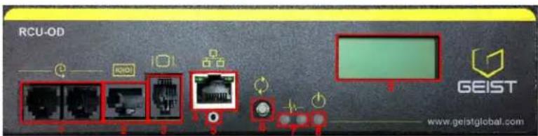
RCU-OD GEIST www.geistglobal.comTables
Tables presented in this document are identified and designated as follows:
'Table:', Chapter # - Image #
Example:
Table 1-1 Name and/or Title goes here
| Column 1 | Column 2 | Column 3 | Column 4 | Column 5 |
| Text | Text | Text | Text | Text |
| Text | Text | Text | Text | Text |
| Text | Text | Text | Text | Text |
| Text | Text | Text | Text | Text |
Chapter 1 - Product Specifications
Overview
The J, MJ and VHV Series products are Power Distribution Units (PDU) intended for connection to 15 or 20 Amp AC Mains. The PDUs are designed to be powered by either a single phase or a three phase AC input circuit. Three phase units can be configured for either a delta or wye input connection. J and VHV Series PDUs can optionally be configured with a Geist Current Meter that provides local monitoring and display of each output circuit current.

NOTE
Global Versions of the VHV Series are intended to be connected to a 16 Amp AC Main Branch Circuit.
Environmental
Temperature
Table 1-1 Temperature Limits
| Minimum | Maximum | |
| Operating | 10°C (50°F) | 45°C (113°F) (J, VHV)25°C (77°F) (MJ) |
| Storage | -25°C (13°F) | 65°C (149°F) |
Humidity
Table 1-2 Humidity Limits
| Minimum | Maximum | |
| Operating | 5% | 95% (non-condensing) |
| Storage | 5% | 95% (non-condensing) |
Elevation
Table 1-3 Elevation Limits
| Minimum | Maximum | |
| Operating | 0 m (0 ft) | 2,000 m (6561 ft) |
| Storage | 0 m (0 ft) | 15,240 m (50,000 ft) |
Electrical
Electrical product characteristics an performance are defined below. Also, please see the product nameplate for additional rating limits.
Receptacle Ratings
Table 1-4 Receptacle Ratings
| Type | Ratings |
| NEMA 5-15R or L5-15R | 125Vac, 12A |
| NEMA 5-20R or L5-20R | 125Vac, 16A |
| NEMA 6-20R or L6-20R | 250Vac, 16A |
| IEC-60320 C13 | 250Vac, 10A (UL & CSA 12A, 250Vac) |
| IEC-60320 C19 | 250Vac, 16A (UL & CSA 16A, 250Vac) |
Regulatory Compliance
Geist products are regulated for Safety, Emissions, and Environment Impact per the below agencies and policies.
Underwriters Laboratories (UL)
UL Standards are used to assess products; test components, materials, systems and performance; and evaluate environmentally sustainable products, renewable energies, food and water products, recycling systems and other innovative technologies.
The UL standards specific to this equipment are listed in the UL Online Certification Library under the file number noted on the device name plate.
CE
The placement of the CE mark on a product signifies a manufacturer's declaration that the product complies with the applicable European (EU) health, safety, and environmental protection requirements, including EU legislation and product directives. The CE mark is required for products offered for sale within the European Economic Area (EEA).
The specific regulations, directives, and standards applicable to each product are specified on the Declaration of Conformity.
Federal Communications Commission (FCC)
The Federal Communications Commission (FCC) regulates interstate and international communications by radio, television, wire, satellite, and cable in all 50 states, the District of Columbia and U.S. territories. An independent U.S. government agency overseen by Congress, the commission is the United States' primary authority for communications laws, regulation and technological innovation.
The FCC standards specific to this equipment are:
This Class A device complies with part 15 of the FCC Rules. Operation is subject to the following two conditions:
(1) This device may not cause harmful interference
(2) This device must accept any interference received, including interference that may cause undesired operation.
This Class A digital apparatus complies with Canadian ICES-003.
Changes or modifications to this unit not expressly approved by the party responsible for compliance could void the user's authority to operate this equipment.
RoHS/WEEE
Directive 2011/65/EU outlines the restriction of the use of hazardous substances in electrical and electronic equipment (EEE) with a view to contributing to the protection of human health and the environment, including the environmentally sound recovery and disposal of waste EEE.
Restricted substances and their respective maximum concentration values are listed below.
| Restricted Substance | Maximum Concentration Value (w/w) |
| Cadmium (Cd): | 0.01% |
| Mercury (Hg): | 0.10% |
| Lead (Pb): | 0.10% |
| Hexavalent chromium (Cr6+): | 0.10% |
| Polybrominated biphenyls (PBB): | 0.10% |
| Polybrominated diphenyl ethers (PBDE): | 0.10% |
| **Bis(2-Ethylhexyl) phthalate (DEHP): | 0.10% |
| **Butyl Benzyl phthalate (BBP): | 0.10% |
| **Dibutyl phthalate (DBP): | 0.10% |
| **Diisobutyl phthalate (DIBP): | 0.10% |
NOTE
DEHP, BBP, DBP, and DIBP restrictions are in effect as of July 2019.
Chapter 2 - Installation
Installation
- Using appropriate hardware, mount unit to rack. See next section for examples.
- Plug PDU into an appropriately-rated and protected branch-circuit receptacle.
- Plug in the devices to be powered by the PDU.
- Turn on each device connected to the PDU. Sequential power-up is recommended to avoid high inrush current.

NOTE
Branch Circuit should be sized based on the PDU's nameplate electrical rating. A 12 Amp rated PDU is intended for use on a 15 Amp Branch Circuit, while a 16 Amp rated PDU is intended for use on a 20 Amp Branch Circuit. For Global Units a 16 Amp rated PDU is intended for use on a 16 Amp Branch Circuit.
Guidelines
- If the PDU is installed in a cabinet the ambient temperature of the rack should be no greater than 45^ C and 25^ C for the MJ series.
- Install the PDU such that the amount of airflow required for safe operation of equipment is not compromised.
- Mount the PDU so that a hazardous condition is not achieved due to uneven mechanical loading.
- Follow nameplate ratings when connecting equipment to the branch circuit. Take into consideration the effect that overloading of the circuits might have on over-current protection and supply wiring.
- The PDU relies on the building installation for protection from over-current conditions. A certified overcurrent protection device is required in the building installation. The overcurrent protection device should be sized according to the PDU's nameplate ratings and local/national electrical codes.
- Reliable earthing of rack-mount equipment should be maintained. Particular attention should be given to supply connections other than direct connections to the branch circuit. The PDU must be connected to an earthed socket-outlet.***
- The PDU is intended for Restricted Access Locations only and only qualified service personnel should install and access the PDU.
- For pluggable equipment, install the PDU so that the input plug or appliance coupler may be disconnected for service.
- Sequential power-up of devices powered by the PDU is recommended to avoid high inrush current.
- Caution: Disconnect all power cords before servicing.
- The PDU is intended for use with TN, TT, or IT power supply systems
NOTE
J Series PDUs may optionally be configured as Isolated Ground units. All Isolated Ground units will be shipped with an enclosure grounding cable. This cable must be connected between the enclosure and a reliable safety ground.
Mounting
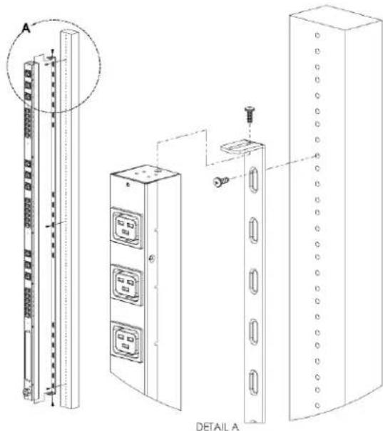
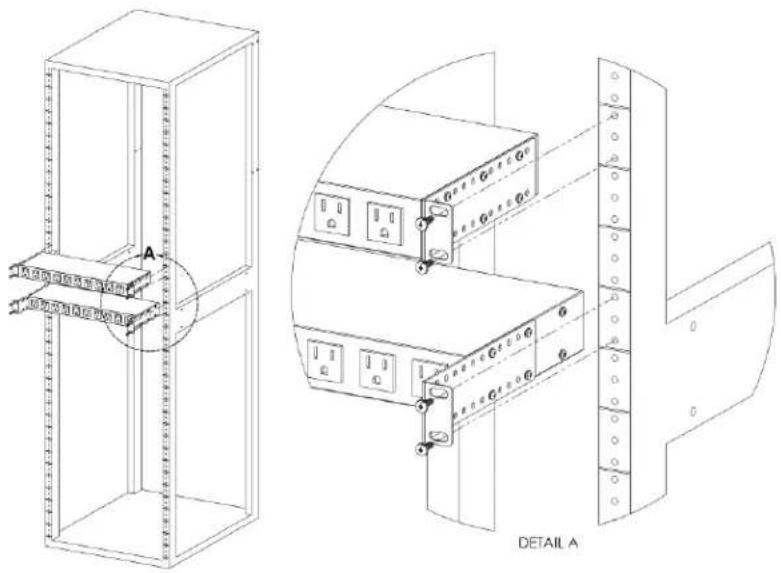
Figure 2-1 Full Length Bracket
text_image
A DETAIL AFull Length Bracket
Using the full length bracket, mount PDU to rack as shown
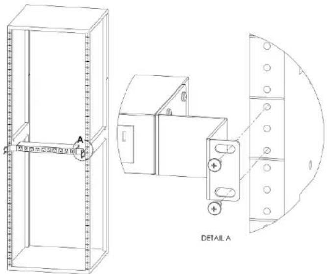
Figure 2-2 Mini L Brackets

text_image
DETAIL A A B DETAIL BMini "L" Brackets (SLB-4)
Using the mini "L" brackets, attach PDU to rack as shown
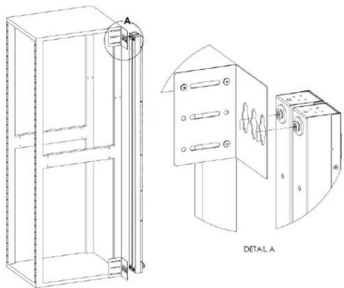
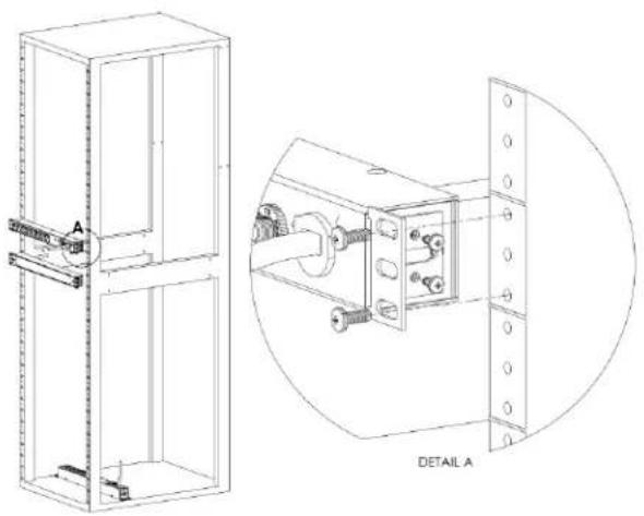
Figure 2-3 Vertical Extension Brackets

text_image
DETAIL A A B DETAIL BVertical Extension Brackets (VCB-1)
Using the vertical extension brackets, attach PDU to rack as shown
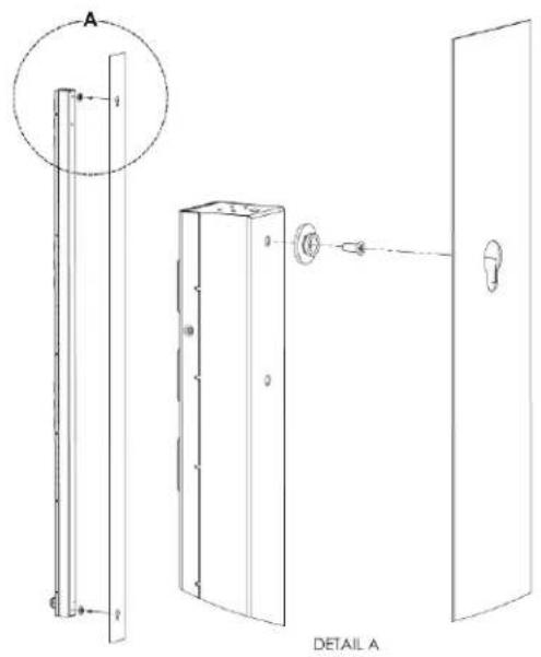
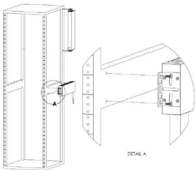
Figure 2-4 Toolless Mounting Hardware
text_image
A DETAIL AToolless Mounting Hardware (11621)
Secure toolless mounting buttons to PDU as shown. Use toolless buttons with key-holed slots built into cabinet or with optional Geist key-holed brackets.
Figure 2-5 Toolless Full Length Brackets

text_image
TOOLLESS SHOULDER WASHER A DETAIL AToolless Full Length Bracket (TLFL)
Using full length toolless bracket and toolless mounting buttons, attach PDU to rack as shown
Figure 2-6 Single Side Mount 2 Units Brackets
text_image
A B DETAIL ASingle Side Mount 2 Unit Brackets (TSMX2)
Using single side mount 2 unit brackets and toolless mounting buttons, attach PDU to rack as shown
Figure 2-7 Offset/Side Mount Brackets

text_image
LEFT SIDE OPTION DETAIL A A B C RIGHT SIDE OPTION DETAIL B DETAIL COffset/Side Mount Brackets (EZB-1)
Using the offset/side mount brackets, attach PDU to rack as shown.
Figure 2-8 7" Extension Brackets

text_image
A B DETAIL A DETAIL B7" Extension Brackets (XB-7)
Using the 7" extension brackets, attach PDU to rack as shown
Figure 2-9 Flush Mount Brackets
text_image
DETAIL AFlush Mount Brackets (FM)
Using flush mount brackets, attach PDU to rack as shown
Figure 2-10 Adjustable Mount Brackets
text_image
A B C D E F G H I J K L M N O P Q R S T U V W X Y Z A DETAIL AAdjustable Mount Brackets (AM)
Using adjustable mount brackets, attach PDU to rack as shown
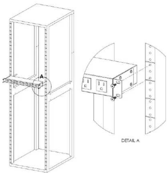
Figure 2-11 Panel Mount Brackets
text_image
A DETAIL APanel Mount Brackets (PM)
Using panel mount brackets, attach PDU to rack as shown
Figure 2-12 23" Conversion Mounting Brackets
text_image
DETAIL A23" Conversion Mounting Brackets (23-RM)
Using conversion mounting brackets, attach 19" PDU to 23" rack as shown
Figure 2-13 Cable Mount Brackets

text_image
DETAIL A DETAIL BCable Mount Bracket (CMB-1)
Attach cable mount bracket to PDU as shown; use tie-wraps to secure cords to bracket
Figure 2-14 19" Horizontal/Panel Mount Brackets
natural_image
Technical line drawing of a mechanical assembly with two views: top shows a vertical frame with internal components, bottom shows a close-up of a mechanical component (no text or symbols)19" Horizontal/Panel Mount Brackets (7938)
Using the 19" horizontal/panel mount brackets, attach PDU to rack as shown
Chapter 3 - Setup
Optional Local Monitoring
Power Meter
The Geist PM-1 power meter is a low-power, high accuracy meter capable of measuring true RMS Current, Voltage, Power, and Power Factor. These values are individually shown on an easy to read, 4-digit LED Display, which continuously scrolls through the four different measured values. Each one of these displayed parameters is defined below. The Power Meter will automatically begin cycling through the displayed values when the PDU is connected to AC Mains power.
- Current: PDU output current draw measured in true RMS Amps
• Voltage: PDU output voltage measured in true RMS Voltage
• Power: PDU output power measured in Watts – referred to as real or active power
• Power Factor: Ration of real PDU output power to apparent PDU output power4
Figure 3-1 Power Meter

text_image
POWER METER 1.08V POWER FACTOR AMPS VOLTS WATTSPower Meter Display
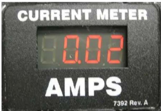
Current Meter
The Geist CM-1 current meter is a low-power, high accuracy meter capable of measuring true RMS Current. The value of current is continuously shown on an easy to read, 4-digit LED Display. The Current Meter will automatically begin to display value of output current when the PDU is connected to AC Mains power.
Figure 3-2 Current Meter
text_image
CURRENT METER 8.02 AMPS 7392 Rev. ACurrent Meter Display
Chapter 4 - Final Checkout
Final Checkout
Technical Support
Service and Maintenance
No service or maintenance is required. Do not attempt to open the PDU or you may void the warranty. There are no serviceable parts inside the PDU other than the field replaceable Interchangeable Monitoring Device (IMD). It is recommended that power be removed from the unit before installing or removing any equipment.
The Interchangeable Monitoring Device is designed to be field replaceable by qualified service personnel only. The IMD is designed to be replaced while the PDU is still connected to AC Mains power. Please refer to the IMD section of this document for removal and installation instructions.
More Technical Support
http://geistglobal.com
Americas
• 1 888 630 4445
Europe and Middle East
• From within the UK 0845 026 3853
• From abroad +44 845 026 3853
Asia
• English +1 888 630 4445 (US number)
• Chinese + 86 755 8663 9505
Email: support@geistglobal.com or contact your distributor Technical Support Form: http://www.geistglobal.com/Tech-Support
Product-Specific Safety Notices
The specific procedural safety precautions relating to this product are stated below.
General Safety
Safety is a serious matter and all precautions should to taken to guarantee a safe work and operational environment. General safety precautions must be observed during all aspects of operation, service, and repair of equipment described in this document. Failure to comply with the safety warnings, procedures and guidelines as presented in this document is in violation of the safety standards of design, manufacture, and intended use of this equipment.
You are responsible for following the safety guidelines and warnings presented in this document for this equipment. Individuals using or maintaining Geist product(s) are expected to follow all the noted warnings and safety precautions necessary for safe operation of the equipment in your environment. Geist assumes no liability for failure to comply with these requirements.
Live Circuits Safety

DANGER
HAZARDOUS VOLTAGE, CURRENT, AND ENERGY LEVELS ARE PRESENT IN THIS PRODUCT. POWER SWITCHED CIRCUITS CAN HAVE HAZARDOUS VOLTAGES PRESENT EVEN WHEN THE SWITCH IS IN THE OFF POSITION. DO NOT OPERATE THE PRODUCT WITH ANY COVER PLATE REMOVED. ALWAYS MAKE SURE THAT PRODUCT IS FULLY ENCLOSED PRIOR TO USE.
Operating personnel must:
- Not remove equipment covers. Only Geist Authorized Service Personnel or other qualified maintenance personnel may remove equipment covers for internal sub-assembly, or component replacement, or any internal adjustment.
- Not replace any equipment component with power applied to the line cord. Under certain conditions, dangerous voltages may exist even with the input power cable disconnected. Any exceptions for 'Hot-Swap' modules will be specifically noted in this product document.
- Always disconnect input power and discharge circuits before touching any sub-assembly of circuit component.
Equipment Grounding
To minimize shock hazard, the equipment chassis and enclosure must be connected to an electrical earth ground. The input power cable must be either plugged into an industry electrical code compatible receptacle or wired directly into an electrical code compatible interface. The equipment earth ground wire (typically green) must be firmly connected to the
facility electrical safety ground. The mating electrical interface to this equipment must comply with International Electromechanical Commission (IEC) standards.
Electrostatic Discharge
Geist strongly recommends that an anti-static precautions be taken when installing, removing, or working on and around static sensitivity equipment. Industry approved anti-static devices such as wrist and heel straps, in conjunction with conductive foam pads, should be available and implemented only after verifying that they are in good working condition.
Electronic components such as memory modules, circuit boards, and LED displays, are sensitivity to Electro-Static Discharge (ESD). Handling of such components should be done only after proper anti-static workspace conditions have been established. Any static producing packing materials such as plastic, Styrofoam, and some cardboards, should be removed and discarded in a timely manner.
Explosive Environment
Do not operate this equipment in the presence of flammable gases or fumes. Operation of any electrical equipment in such an environment constitutes a definite safety hazard.
Servicing and Adjustments
Do not attempt to service this equipment, there are no field serviceable parts or sub-assemblies. Any adjustments should be made by authorized service personnel only.
Repairs and Modifications
Because of the danger of electrocution and/or severe health hazard, do not install substitute parts or preform any unauthorized modifications of this equipment. It is best to contact Geist for Warranty and Repair Service to ensure that safety features are maintained.

natural_image
Orange hexagonal logo with abstract geometric shapes (no text or symbols)GEIST
POWER
Thank You For Purchasing Geist
geistglobal.com