SuperServer SYS-E403-12P-FN2T - Server Supermicro - Free user manual and instructions
Find the device manual for free SuperServer SYS-E403-12P-FN2T Supermicro in PDF.

User questions about SuperServer SYS-E403-12P-FN2T Supermicro
0 question about this device. Answer the ones you know or ask your own.
Ask a new question about this device
Download the instructions for your Server in PDF format for free! Find your manual SuperServer SYS-E403-12P-FN2T - Supermicro and take your electronic device back in hand. On this page are published all the documents necessary for the use of your device. SuperServer SYS-E403-12P-FN2T by Supermicro.
USER MANUAL SuperServer SYS-E403-12P-FN2T Supermicro
natural_image
Back view of a black server rack with front panel, ports, and ventilation grilles (no visible text or labels)USER'S MANUAL
Revision 1.0a
The information in this User's Manual has been carefully reviewed and is believed to be accurate. The vendor assumes no responsibility for any inaccuracies that may be contained in this document, and makes no commitment to update or to keep current the information in this manual, or to notify any person or organization of the updates. Please Note: For the most up-to-date version of this manual, please see our website at www.supermicro.com.
Super Micro Computer, Inc. ("Supermicro") reserves the right to make changes to the product described in this manual at any time and without notice. This product, including software and documentation, is the property of Supermicro and/or its licensors, and is supplied only under a license. Any use or reproduction of this product is not allowed, except as expressly permitted by the terms of said license.
IN NO EVENT WILL Super Micro Computer, Inc. BE LIABLE FOR DIRECT, INDIRECT, SPECIAL, INCIDENTAL, SPECULATIVE OR CONSEQUENTIAL DAMAGES ARISING FROM THE USE OR INABILITY TO USE THIS PRODUCT OR DOCUMENTATION, EVEN IF ADVISED OF THE POSSIBILITY OF SUCH DAMAGES. IN PARTICULAR, SUPER MICRO COMPUTER, INC. SHALL NOT HAVE LIABILITY FOR ANY HARDWARE, SOFTWARE, OR DATA STORED OR USED WITH THE PRODUCT, INCLUDING THE COSTS OF REPAIRING, REPLACING, INTEGRATING, INSTALLING OR RECOVERING SUCH HARDWARE, SOFTWARE, OR DATA.
Any disputes arising between manufacturer and customer shall be governed by the laws of Santa Clara County in the State of California, USA. The State of California, County of Santa Clara shall be the exclusive venue for the resolution of any such disputes. Supermicro's total liability for all claims will not exceed the price paid for the hardware product.
FCC Statement: This equipment has been tested and found to comply with the limits for a Class A or Class B digital device pursuant to Part 15 of the FCC Rules. These limits are designed to provide reasonable protection against harmful interference when the equipment is operated in industrial environment for Class A device or in residential environment for Class B device. This equipment generates, uses, and can radiate radio frequency energy and, if not installed and used in accordance with the manufacturer's instruction manual, may cause harmful interference with radio communications. Operation of this equipment in a residential area is likely to cause harmful interference, in which case you will be required to correct the interference at your own expense.
California Best Management Practices Regulations for Perchlorate Materials: This Perchlorate warning applies only to products containing CR (Manganese Dioxide) Lithium coin cells. "Perchlorate Material-special handling may apply. See www.dtsc.ca.gov/hazardouswaste/perchlorate".

WARNING: This product can expose you to chemicals including lead, known to the State of California to cause cancer and birth defects or other reproductive harm. For more information, go to www.P65Warnings.ca.gov.
The products sold by Supermicro are not intended for and will not be used in life support systems, medical equipment, nuclear facilities or systems, aircraft, aircraft devices, aircraft/emergency communication devices or other critical systems whose failure to perform be reasonably expected to result in significant injury or loss of life or catastrophic property damage. Accordingly, Supermicro disclaims any and all liability, and should buyer use or sell such products for use in such ultra-hazardous applications, it does so entirely at its own risk. Furthermore, buyer agrees to fully indemnify, defend and hold Supermicro harmless for and against any and all claims, demands, actions, litigation, and proceedings of any kind arising out of or related to such ultra-hazardous use or sale.
Manual Revision 1.0a
Release Date: February 01, 2022
Unless you request and receive written permission from Super Micro Computer, Inc., you may not copy any part of this document. Information in this document is subject to change without notice. Other products and companies referred to herein are trademarks or registered trademarks of their respective companies or mark holders.
Copyright © 2022 by Super Micro Computer, Inc.
All rights reserved.
Printed in the United States of America
Preface
About this Manual
This manual is written for professional system integrators and PC technicians. It provides information for the installation and use of the server. Installation and maintenance should be performed by experienced technicians only.
Please refer to the SYS-E403-12P-FN2T server specifications page on our website for updates on supported memory, processors, and operating systems (http://www.supermicro.com).
Notes
For your system to work properly, please follow the links below to download all necessary drivers/utilities and the user's manual for your server.
- Supermicro product manuals: http://www.supermicro.com/support/manuals/
- Product drivers and utilities: https://www.supermicro.com/wdl/driver
- Product safety info: http://www.supermicro.com/about/policies/safety_information.cfm
If you have any questions, please contact our support team at:
support@supermicro.com
This manual may be periodically updated without notice. Please check the Supermicro website for possible updates to the manual revision level.
Secure Data Deletion
A secure data deletion tool designed to fully erase all data from storage devices can be found on our website: https://www.supermicro.com/about/policies/disclaimer.cfm?url=/wdl/utility/Lot9_Secure_Data_Deletion_Utility/
Warnings
Special attention should be given to the following symbols used in this manual.

Warning! Indicates important information given to prevent equipment/property damage or personal injury.

Warning! Indicates high voltage may be encountered when performing a procedure.
Contents
Contacting Supermicro....7
Chapter 1 Introduction
1.1 Overview....8
1.2 System Features 9
Rear View....9
Front View....10
Control Panel....11
Top View....12
1.3 System Architecture ....13
Main Components....13
1.4 Motherboard Layout....14
Quick Reference Table....15
Chipset Block Diagram....17
Chapter 2 Server Installation
2.1 Overview....18
2.2 Unpacking the System ....18
2.3 Preparing for Setup....18
Choosing a Setup Location....18
Rack Precautions....19
Server Precautions....19
Rack Mounting Considerations....19
Ambient Operating Temperature....19
Airflow 20
Mechanical Loading....20
Circuit Overloading....20
Reliable Ground....20
2.4 Wall Mount Procedure....21
Chapter 3 Maintenance and Component Installation
3.1 Removing Power....24
3.2 Accessing the System....25
3.3 Processor and Heatsink Installation....29
The Processor Carrier Assembly 30
The Processor Heatsink Module (PHM)....32
Installing the PHM into the CPU Socket....33
Removing the PHM from the CPU Socket 36
Removing the Processor Carrier Assembly from the PHM 37
Removing the Processor from the Carrier Assembly....38
3.4 Memory....39
Memory Support....39
General Guidelines for Optimizing Memory Performance 39
DIMM Installation 40
DIMM Removal 40
3.5 Motherboard Battery....41
3.6 Storage Drives....42
Hard Drives 42
M.2 Solid State Drives 45
3.7 PCI Expansion Cards....46
3.8 System Cooling....48
Fans 48
Air Shrouds....49
Checking the Server Air Flow....51
Overheating ....51
3.9 Power Supply 52
Power Supply Failure....52
3.10 Cable Routing Diagram....54
Chapter 4 Motherboard Connections
4.1 Power Connections ....55
4.2 Headers and Connectors ....57
Headers....57
4.3 Input/Output Ports 62
Rear I/O Ports....62
4.4 Jumpers....63
4.5 LED Indicators....65
Chapter 5 Software
5.1 Microsoft Windows OS Installation....67
5.2 Driver Installation....69
5.3 SuperDoctor® 5....70
5.4 BMC....71
BMC ADMIN User Password ....71
Chapter 6 Optional Components
6.1 Optional Parts List....72
6.2 GPU Auxiliary Power Cable 72
Chapter 7 Troubleshooting and Support
7.1 Information Resources....73
Website 73
Direct Links for the SYS-E403-12P-FN2T System....73
Direct Links for General Support and Information....74
7.2 Intelligent Platform Management Interface (IPMI)....75
7.3 Troubleshooting Procedures ....76
General Technique....76
No Power 76
No Video ....77
System Boot Failure....77
Memory Errors ....77
Losing the System Setup Configuration ....77
When the System Becomes Unstable....77
7.4 Crash Dump Using IPMI 79
7.5 Where to Get Replacement Components....80
7.6 Reporting an Issue....80
Technical Support Procedures....80
Returning Merchandise for Service....80
Vendor Support Filing System 81
7.7 Feedback....81
7.8 Contacting Supermicro....82
Appendix A Standardized Warning Statements for AC Systems
Appendix B System Specifications
Contacting Supermicro
Headquarters
Address: Super Micro Computer, Inc.
980 Rock Ave.
San Jose, CA 95131 U.S.A.
Tel: +1 (408) 503-8000
Fax: +1 (408) 503-8008
Email: marketing@supermicro.com (General Information)
support@supermicro.com (Technical Support)
Website: www.supermicro.com
Europe
Address: Super Micro Computer B.V.
's-Hertogenbosch, The Netherlands
Tel: +31 (0) 73-6400390
Fax: +31 (0) 73-6416525
Email: sales@supermicro.nl (General Information)
support@supermicro.nl (Technical Support)
rma@supermicro.nl (Customer Support)
Website: www.supermicro.nl
Asia-Pacific
Address: Super Micro Computer, Inc.
3F, No. 150, Jian 1st Rd.
Zhonghe Dist., New Taipei City 235
Taiwan (R.O.C)
Tel: +886-(2) 8226-3990
Fax: +886-(2) 8226-3992
Email: support@supermicro.com.tw
Website: www.supermicro.com.tw
Chapter 1
Introduction
1.1 Overview
This chapter provides a brief outline of the functions and features of the SuperServer SYS-E403-12P-FN2T. It is based on the X12SPW-TF serial motherboard and the CSE-E403iF-000NBP chassis.
The following provides an overview of the specifications and capabilities.
| System Overview | |
| Motherboard | X12SPW-TF-001 |
| Chassis | CSE-E403iF-000NBP |
| Processor Support | 3rd Gen Intel® Xeon® Scalable processors |
| Memory | Eight DIMM slots, up to 2TB ECC LRDIMM, DDR4-3200MHz |
| Drive Support | Four [xed internal 2.5" SATA3 drive bays |
| Expansion Slots | Three PCIe 4.0 x16 slotsOne M.2 PCIe 3.0 x4/SATA3 slot (supports M-Key 2280 and 22110) |
| I/O Ports | Two LAN 10GbE portsOne RJ45 dedicated IPMI LAN portOne VGA portOne COM portFour USB 3.0 ports, two USB 2.0 ports |
| System Cooling | Three 8 x 3.8cm heavy duty fansOne CPU heatsink, and one air shroud to direct airflow |
| Power | One 600W AC power supply, 80 Plus Gold Certified |
| Form Factor | Box; (WxHxD) 10.5 x 4.3 x 16in (267 x 109 x 406mm) |
Note: The Quick Reference Guide can be found on the product page for SYS-E403-12P-FN2T.
Note: The following safety agency or regulatory models associated with the SYS-SYS-E403-12P-FN2T have been certified as compliant with UL or CSA: E403iF-S6X12, E403iF-6.
1.2 System Features
The following views of the system display the main features. Refer to Appendix B for additional specifications.
Rear View

text_image
FansFigure 1-1. Rear View
| System Features: Rear | |
| Feature Description | |
| Fans Three system fans | |
Front View

text_image
IPMI LAN Port Power Supply COM Port USB Ports LAN Ports VGA Port Control PanelFigure 1-2. SYS-E403-12P-FN2T: Front View
System Features: Front
| Feature Description | |
| Power Supply 600W | 80Plus Gold level power supply module |
| Ground Two ground | screws provided to attach the chassis to an electrical ground |
| COM Serial port | |
| IPMI LAN IPMI LAN | port |
| USB Four USB 3.0 | ports, two USB 2.0 ports |
| LAN Two 10GbE LAN | ports |
| VGA Video port | |
| Control Panel See the next page for details. | |
Expansion Slot Locations
| Item Description | |
| 1 | PCIe 4.0 x16 slot: full-height, full-length |
| 2 | PCIe 4.0 x16 slot: full-height, full-length |
| 3 | PCIe 4.0 x16 slot: full-height, full-length |
Control Panel

text_image
Power Button Reset Button RESET Power LED NIC LEDs Power LED HDD LED Overheat LEDFigure 1-3. Control Panel
| Control Panel Features | |
| Feature Description | |
| Power button | The main power switch applies or removes primary power from the power supply to the server but maintains standby power. |
| Reset button Reboots the system. | |
| Power LED | Indicates power is being supplied to the system power supply units. This LED is illuminated when the system is operating normally. |
| NIC LEDs Indicate network activity on LAN1 and LAN2 when flashing. | |
| Power Fail LED Indicates a power supply module has failed. | |
| HDD LED Indicates activity on the hard drive when flashing. | |
| Overheat LED Indicates an overheat condition. | |
Caution: Since the system continues to draw a small amount of power in standby mode (and fans are off), there is a potential for overheating if the system is idle for a long time. In this situation, there is no warning from the overheat/fan fail LED.
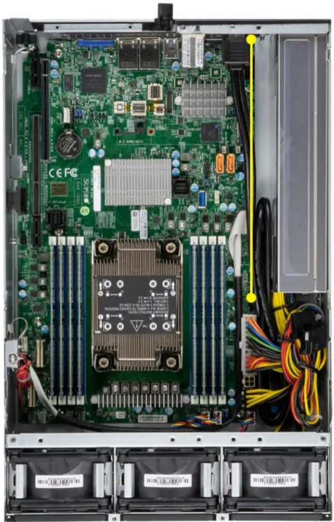
Top View
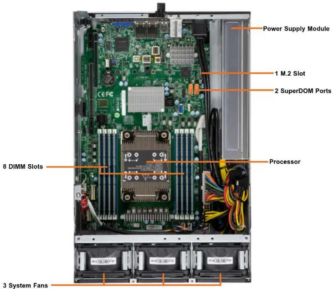
text_image
Power Supply Module 1 M.2 Slot 2 SuperDOM Ports 8 DIMM Slots Processor 3 System FansFigure 1-4. System: Top View
| System Features: Top | |
| Feature Description | |
| Power Supply Single | 600W module |
| M.2 slot Single PCIe | 3.0 x4/SATA3 M.2 |
| SuperDOM ports | Disk-on-Module port allows for flash cards to be mounted directly on the motherboard |
| DIMM slots Dual in-line | memory module (DIMM) slots |
| Processor Intel Xeon | Scalable Processor |
| System fans 8 x 3.8cm | heavy duty fans used to provide cooling for the system |
1.3 System Architecture
This section covers the locations of the electrical components of the motherboard and the overall system.
Main Components

text_image
RSC-W2R-666G4 X12SPW-TF-001Figure 1-5. Main Component Locations
1.4 Motherboard Layout
Below is a layout of the X12SPW-TF-001 motherboard with jumper, connector, and LED locations shown. See the table on the following page for descriptions. For detailed descriptions, pinout information, and jumper settings, refer to Chapter 4 or the motherboard manual.

text_image
UID-LED UID-SW VGA USB4/5 (3.0) UPM1 LAN USB0/1 COM1 SXB1A JPL2 COM2 LEDBMC JNCSI1 JPL1 SXB2 JNCSI2 J12C_EXP1 JPL3 M.2-H JPME1 JSD1 BT1 JSD2 S-SATA0 JPT1 S-SATA1 USB2/3 TPM/PORT80 JRT1 JBT1 USB6/7(3.0) JRK1 USB8(3.0) BMC Password Label SXB1B I-SATA4~7 CEFC I-SATA0~3 SXB1C S-SGPIO1 SUPER X12SPW-TF/F REV: 2.00 DESIGNED IN USA CPU DIMMC1 DIMMD1 DIMMA1 JSTBY1 DIMMF1 DIMME1 DIMMH1 DIMMG1 JPI2C1 JPWR3 CPU JNVI2C JIPMB1 NVME2/3 JPWR2 JPWR1 JVRM1 JVRM2 FAN1 NVME0/1 JL1 FAN6 FAN5 FAN4 FAN3 FAN2 FAN7 FAN5 FAN4 FAN3 FAN2Figure 1-6. Motherboard Layout
Quick Reference Table
Jumper Description Default Setting
| JBT1 CMOS Clear Open (Normal) |
| JPL3 LAN1/2 Enable/Disable Pins 1-2 (Enabled) |
| JPME1 ME Manufacturing Mode Pins 1-2 (Normal) |
LED Description Status
| LE3 Power LED Solid Green: Power On | |
| LE4 M.2 HDD LED Blinking Green: Device Working | |
| LEDBMC BMC Heartbeat LED Blinking Green: BMC Normal | |
| UID-LED Unit Identifier (UID) LED | Solid Blue: Unit Identified |
Connector Description
| BT1 Onboard CMOS Battery | |
| COM1, COM2 | COM Port, COM Header |
| FAN1 ~ FAN7 | CPU/System Fan Headers |
| I-SATA0 ~ I-SATA7 | Intel® PCH SATA 3.0 Ports (with RAID 0, 1, 5, 10) |
| IPMI_LAN | Dedicated IPMI LAN Port |
| JF1 Front Control Panel Header | |
| JI2C_EXP1 | 4-pin BMC External I^2C Header (for internal testing only) |
| JIPMB1 4-pin BMC External I | ^2C Header |
| JL1 | Chassis Intrusion Header |
| JNCSI1 NC-SI Header for IPMI Support | |
| JNVI ^2C | NVMe I^2C Header |
| JPI ^2C1 | Power System Management Bus (SMB) I^2C Header |
| JPWR1 | 8-pin Power Connector |
| JPWR2 | 4-pin Power Connector |
| JPWR3 | 24-pin ATX Power Connector |
| JRK1 | Intel RAID Key Header |
| JSD1, JSD2 | SATA DOM Power Connectors |
| JSTBY1 | Standby Power Header |
| JVRM1, JVRM2 | SMBus Clock/DATA header connected to CPU/Mem VRMs |
| LAN1, LAN2 | LAN (RJ45) Ports |
| M.2-H | M.2 PCIe 3.0 x4/SATA3 Slot (supports M-Key 2280 and 22110) |
| NVME0/1, NVME2/3 | PCIe 4.0 x8 Slimline SAS Connector |
| SXB1A, SXB1B, SXB1C | Supermicro Proprietary WIO Left Add-on Card Slots |
Connector Description
SXB2 Supermicro Proprietary WIO Right Add-on Card Slot
S-SATA0, S-SATA1 SATA 3.0 Ports with SATA DOM Power
S-SGPIO1 Serial Link General Purpose I/O Connection Header
TPM Trusted Platform Module/Port 80 Connector
UID-SW Unit Identifier (UID) Switch
USB0/1 Back Panel Universal Serial Bus (USB) 2.0 Ports
USB2/3 Front Accessible USB 2.0 Headers
USB4/5 (3.2 Gen 1) Back Panel USB 3.2 Gen 1 Ports
USB6/7 (3.2 Gen 1) Front Accessible USB 3.2 Gen 1 Header
USB8 (3.2 Gen 1) USB 3.2 Gen 1 Type-A Header
VGA VGA Port
Chipset Block Diagram
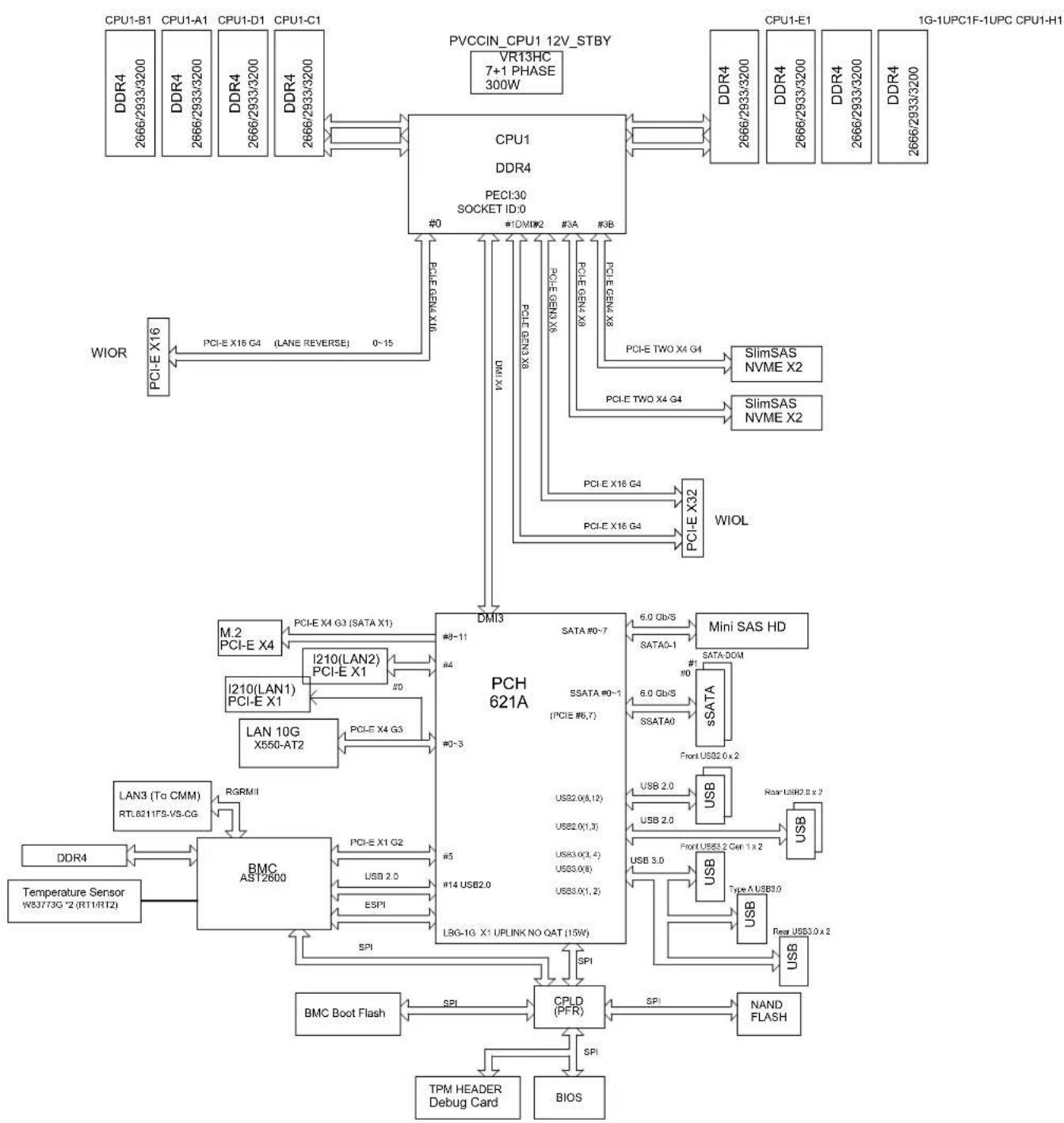
flowchart
System architecture diagram showing CPU, PCH 621A, and BMC AS12800 components with signal paths and data flow between devices like CPU, I/O ports, and memory interfaces.Figure 1-7. Chipset Block Diagram
Chapter 2
Server Installation
2.1 Overview
This chapter provides advice and instructions for mounting your system in a server rack. If your system is not already fully integrated with processors, system memory, etc., refer to Chapter 3 for details on installing those specific components.
Caution: Electrostatic Discharge (ESD) can damage electronic components. To prevent such damage to PCBs (printed circuit boards), it is important to use a grounded wrist strap, handle all PCBs by their edges, and keep them in anti-static bags when not in use.
2.2 Unpacking the System
Inspect the box in which the SuperServer was shipped, and note if it was damaged in any way. If any equipment appears damaged, file a damage claim with the carrier who delivered it. Decide on a suitable location for the rack unit that will hold the server. It should be situated in a clean, dust-free area that is well ventilated. Avoid areas where heat, electrical noise, and electromagnetic fields are generated. It will also require a grounded AC power outlet nearby. Be sure to read the precautions and considerations noted in Appendix A.
2.3 Preparing for Setup
The box in which the system was shipped should include the rackmount hardware needed to install it into the rack. Please read this section in its entirety before you begin the installation.
Choosing a Setup Location
- The system should be situated in a clean, dust-free area that is well ventilated. Avoid areas where heat, electrical noise, and electromagnetic fields are generated.
- Leave enough clearance in front of the rack so that you can open the front door completely (\~25 inches) and approximately 30 inches of clearance in the back of the rack to allow sufficient space for airflow and access when servicing.
- This product should be installed only in a Restricted Access Location (dedicated equipment rooms, service closets, etc.).
- This product is not suitable for use with visual display workplace devices according to §2 of the German Ordinance for Work with Visual Display Units.
Rack Precautions
- Ensure that the leveling jacks on the bottom of the rack are extended to the floor so that the full weight of the rack rests on them.
- In single rack installations, stabilizers should be attached to the rack. In multiple rack installations, the racks should be coupled together.
- Always make sure the rack is stable before extending a server or other component from the rack.
- You should extend only one server or component at a time; extending two or more simultaneously may cause the rack to become unstable.
Server Precautions
- Review the electrical and general safety precautions in Appendix A.
- Determine the placement of each component in the rack before you install the rails.
- Install the heaviest server components at the bottom of the rack first and then work your way up.
- Use a regulating uninterruptible power supply (UPS) to protect the server from power surges and voltage spikes and to keep your system operating in case of a power failure.
- Allow any drives and power supply modules to cool before touching them.
- When not servicing, always keep the front door of the rack and all covers/panels on the servers closed to maintain proper cooling.
Rack Mounting Considerations
Ambient Operating Temperature
If installed in a closed or multi-unit rack assembly, the ambient operating temperature of the rack environment may be greater than the room's ambient temperature. Therefore, consideration should be given to installing the equipment in an environment compatible with the manufacturer's maximum rated ambient temperature (TMRA).
Airflow
Equipment should be mounted into a rack so that the amount of airflow required for safe operation is not compromised.
Mechanical Loading
Equipment should be mounted into a rack so that a hazardous condition does not arise due to uneven mechanical loading.
Circuit Overloading
Consideration should be given to the connection of the equipment to the power supply circuitry and the effect that any possible overloading of circuits might have on overcurrent protection and power supply wiring. Appropriate consideration of equipment nameplate ratings should be used when addressing this concern.
Reliable Ground
A reliable ground must be maintained at all times. To ensure this, the rack itself should be grounded. Particular attention should be given to power supply connections other than the direct connections to the branch circuit (i.e. the use of power strips, etc.).

To prevent bodily injury when mounting or servicing this unit in a rack, you must take special precautions to ensure that the system remains stable. The following guidelines are provided to ensure your safety:
- This unit should be mounted at the bottom of the rack if it is the only unit in the rack.
- When mounting this unit in a partially filled rack, load the rack from the bottom to the top with the heaviest component at the bottom of the rack.
- If the rack is provided with stabilizing devices, install the stabilizers before mounting or servicing the unit in the rack.
- Slide rail mounted equipment is not to be used as a shelf or a work space.
2.4 Wall Mount Procedure
The CSE-E403iF-000NBP can be mounted directly on a surface using the mounting brackets and mounting screws or nails. The following procedure describes how to mount the system to a sturdy surface. Note that formal testing has only been performed on dry wall. Use screws or nails of sufficient strength to support the weight of the system.
Mounting the Chassis
- Attach the three mounting brackets to the chassis using the ten M4xL4 screws that came with the system. See the figure below. The mounting bracket along the I/O panel is pre-attached.
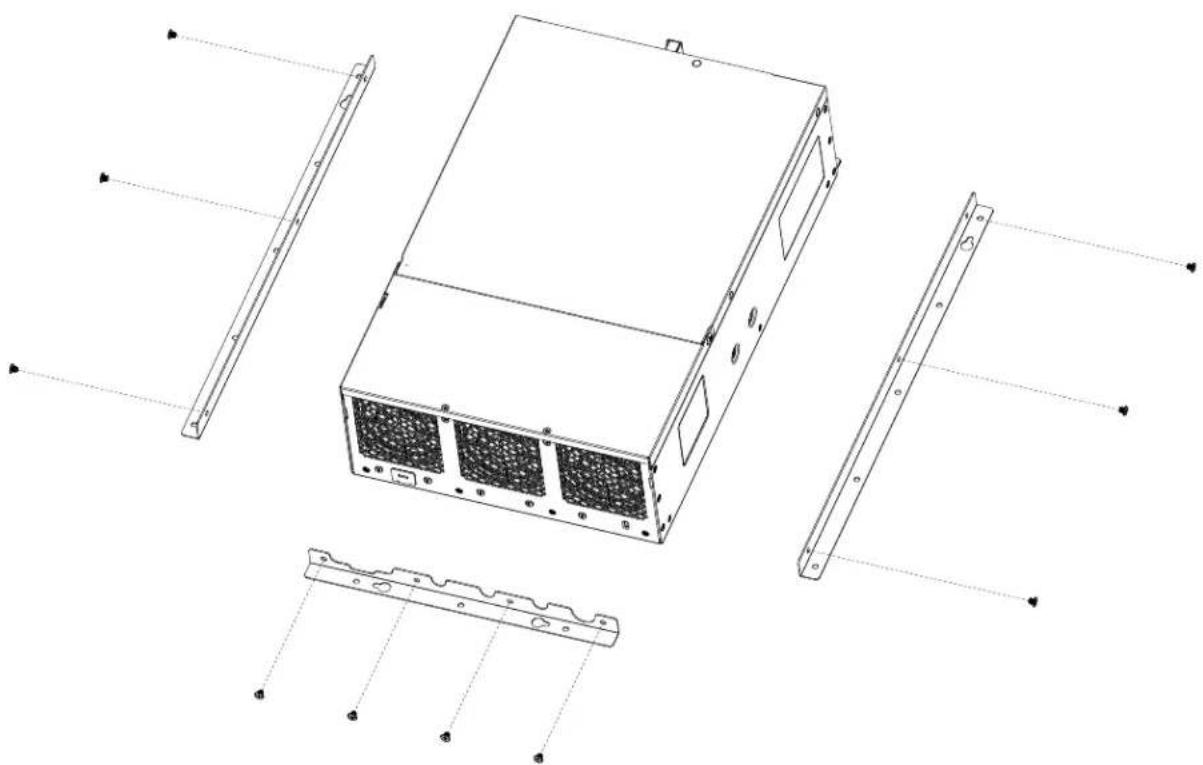
natural_image
Technical line drawing of a server rack with internal components and mounting brackets (no text or symbols)Figure 2-1. Installing the Mounting Brackets
- Decide on an orientation to mount the server. The server can only be mounted with the I/O panel facing left or right.

text_image
76.20 mm 420 mm I/O Facing Left
text_image
76.20 mm 420 mm 76.20 mm I/O Facing RightFigure 2-2. Possible Mounting Orientations
- Mark two keyhole spots on the surface where the server will be mounted. The two keyholes for each orientation are circled in red. See Figure 2-2.
- Install the two keyhole screws or nails.
- Mount the server onto the two screws or nails.
- Install screws or nails in all the holes circled in blue. See Figure 2-2.
Note: The weight of a fully populated system can reach 21lbs (8.3kg).
Chapter 3
Maintenance and Component Installation
This chapter provides instructions on installing and replacing main system components. To prevent compatibility issues, only use components that match the specifications and/or part numbers given.
Installation or replacement of most components require that power first be removed from the system. Please follow the procedures given in each section.
3.1 Removing Power
Use the following procedure to ensure that power has been removed from the system. This step is necessary when removing or installing non hot-swap components or when replacing a non-redundant power supply.
- Use the operating system to power down the system.
- After the system has completely shut down, disconnect the AC power cord(s) from the power strip or outlet. (If your system has more than one power supply, remove the AC power cords from all power supply modules.)
- Disconnect the power cord(s) from the power supply module(s).
3.2 Accessing the System
The CSE-E403iF-000NBP chassis features a removable top cover, which allows easy access to the inside of the chassis.
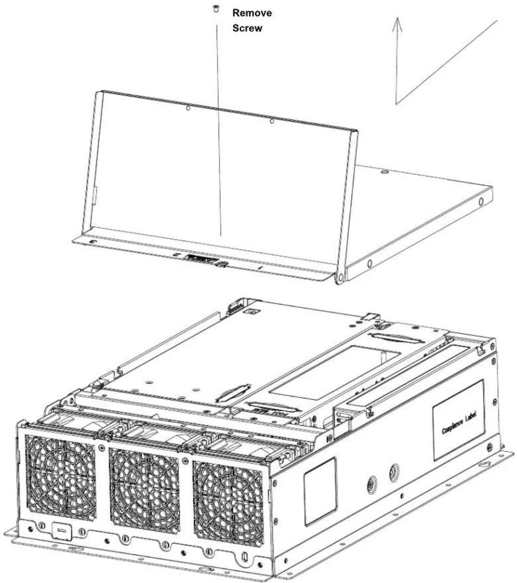
Removing the Chassis Cover
-
Power down the system as described in Section 3.1.
-
Remove the three screws and rotate the rear portion of the cover upward.
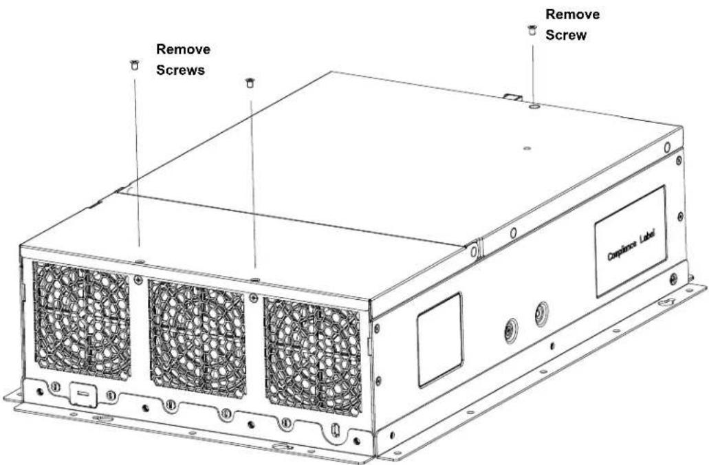
text_image
Remove Screws Remove Screw Compliance LabelFigure 3-1. Removing the Chassis Cover
- Remove the final screw, then slide the cover toward the rear and lift.

Caution: Except for short periods of time, do not operate the server without the cover in place. The chassis cover must be in place to allow proper airflow and prevent overheating.
text_image
Remove Screw Corpliance LabelFigure 3-2. Removing the Chassis Cover
Enabling the Top Cover Lock Function
The chassis includes a lock tab that allows the top cover to be locked.
- Pull the lock tab into a vertical position.
- Close the fan cover. Make sure the lock tab fits through the slot on the cover.
- Install two screws on the fan cover.
- Install a lock on the lock tab.
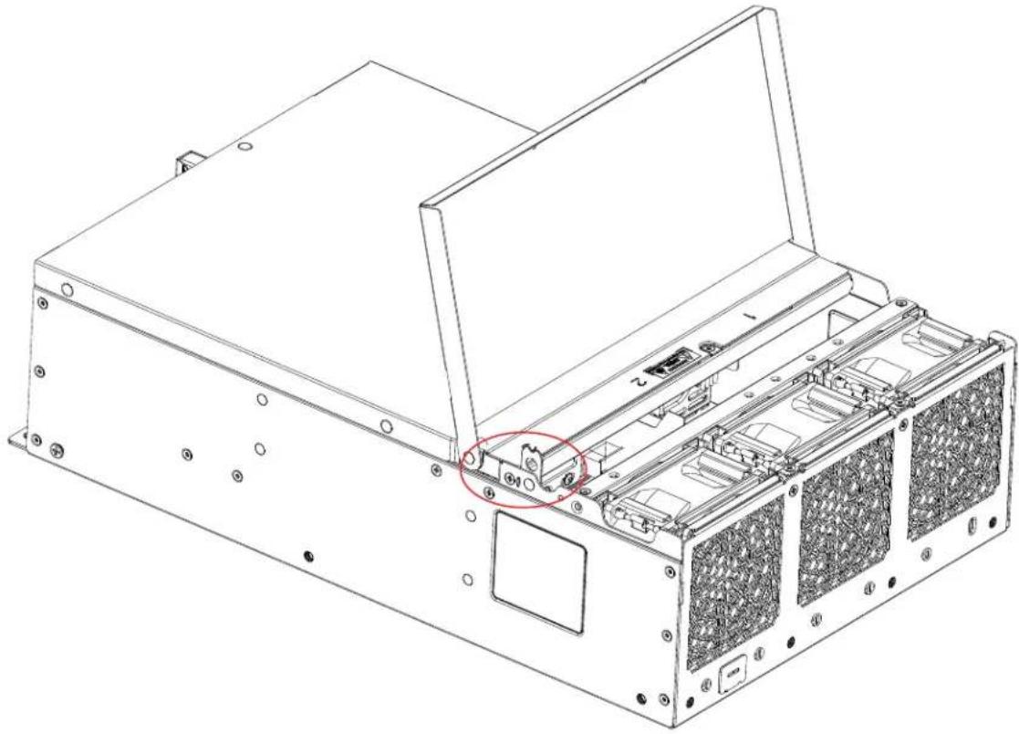
natural_image
Technical line drawing of an internal computer or server unit with mounting holes and a highlighted component (no text or symbols present)Figure 3-3. Pulling the Lock Tab Up
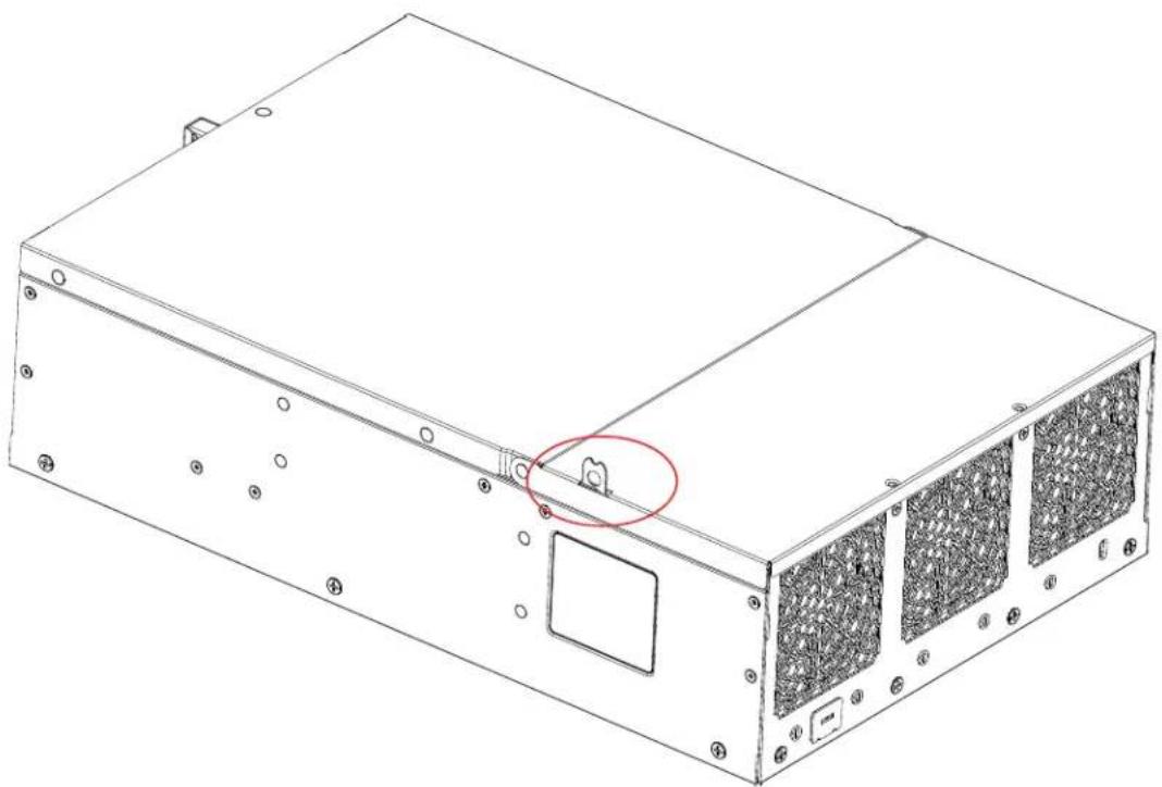
natural_image
Technical line drawing of a computer drive chassis with mounting holes and a red circle highlighting a component (no text or symbols present)Figure 3-4. Top Cover Lock Tab
3.3 Processor and Heatsink Installation
The processor (CPU) and processor carrier should be assembled together first to form the processor carrier assembly. This will be attached to the heatsink to form the processor heatsink module (PHM) before being installed onto the CPU socket.
Notes:
- Use ESD protection.
- Unplug the AC power cord from all power supplies after shutting down the system.
- Check that the plastic protective cover is on the CPU socket and none of the socket pins are bent. If they are, contact your retailer.
- When handling the processor, avoid touching or placing direct pressure on the LGA lands (gold contacts). Improper installation or socket misalignment can cause serious damage to the processor or CPU socket, which may require manufacturer repairs.
• Thermal grease is pre-applied on a new heatsink. No additional thermal grease is needed.
• Refer to the Supermicro website for updates on processor support. - All graphics in this manual are for illustration only. Your components may look different.
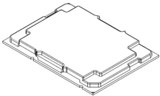
natural_image
Isometric line drawing of a rectangular electronic component with mounting holes and internal channels (no text or symbols)Figure 3-5. Processor
The Processor Carrier Assembly
The processor carrier assembly is comprised of the processor and the processor carrier.
To create the processor carrier assembly, please follow the steps below:
Note: Before installation, be sure to review the Static-Sensitive Devices section earlier in this chapter.
-
Hold the processor with the gold pins (LGA lands) facing down. Locate the gold triangle at the corner of the processor and the corresponding hollowed triangle on the processor carrier as shown below. These triangles indicate the location of pin 1.
-
Turn the processor over (with the gold pins up). Locate the CPU keys on the processor and the four latches on the carrier as shown below.

(with Processor Seated inside the Carrier)
- Locate the lever on the carrier and press it down as shown below.
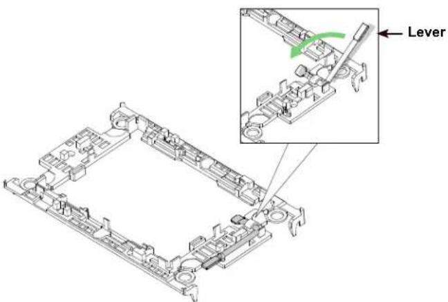
text_image
Lever- Using pin 1 as a guide, carefully align the CPU keys on the processor (A & B) with those on the carrier (a & b) as shown below.

text_image
CPU Key (on the processor) CPU Key (on the carrier) Latch 1 2 A a CPU Key (on the processor) CPU Key (on the carrier) Latch-
Once aligned, carefully place one end of the processor under latch 1 on the carrier, and then press the other end down until it snaps into latch 2.
-
After the processor is placed inside the carrier, examine the four sides of the processor, making sure that the processor is properly seated on the carrier.
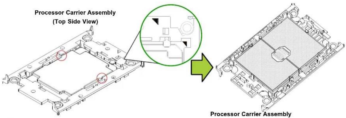
text_image
Processor Carrier Assembly (Top Side View) Processor Carrier AssemblyThe Processor Heatsink Module (PHM)
After creating the processor carrier assembly, mount the heatsink onto the carrier assembly to form the processor heatsink module (PHM).
Note: If this is a new heatsink, the thermal grease has been pre-applied. Otherwise, apply the proper amount of thermal grease to the underside of the heatsink.
-
Turn the heatsink over with the thermal grease facing up. Note the two triangle cutouts (A, B) located at the diagonal corners of the heatsink as shown in the drawing below.
-
On the processor carrier assembly, find pin 1, as noted by the triangles. Hold the processor carrier assembly over so that the gold LGA is facing up.
-
Align clip "a" (pin 1) on the carrier assembly with the triangular cutout A on the heatsink and b, c, d on the carrier assembly with B, C, D on the heatsink.
-
Push the carrier assembly onto the heatsink, making sure that all four clips on each corner are properly secured.

text_image
Processor Carrier Assembly a b d Pin1 C D B A C HeatsinkInstalling the PHM into the CPU Socket
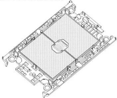
- Remove the plastic protective cover from the CPU socket. Gently squeeze the grip tabs, then pull the cover off.

text_image
CPU Socket with Plastic Protective Cover Grip Tabs- Locate four threaded fasteners (a, b, c, d) on the CPU socket.
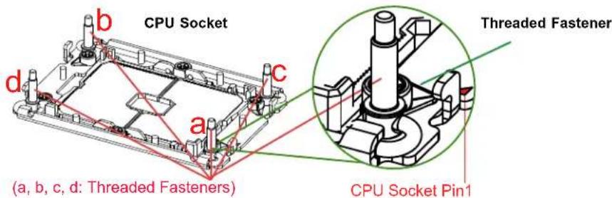
text_image
CPU Socket Threaded Fastener a b c d (a, b, c, d: Threaded Fasteners) CPU Socket Pin1- Locate four PEEK nuts (A, B, C, D) and four rotating wires (1, 2, 3, 4) on the heatsink as shown below.
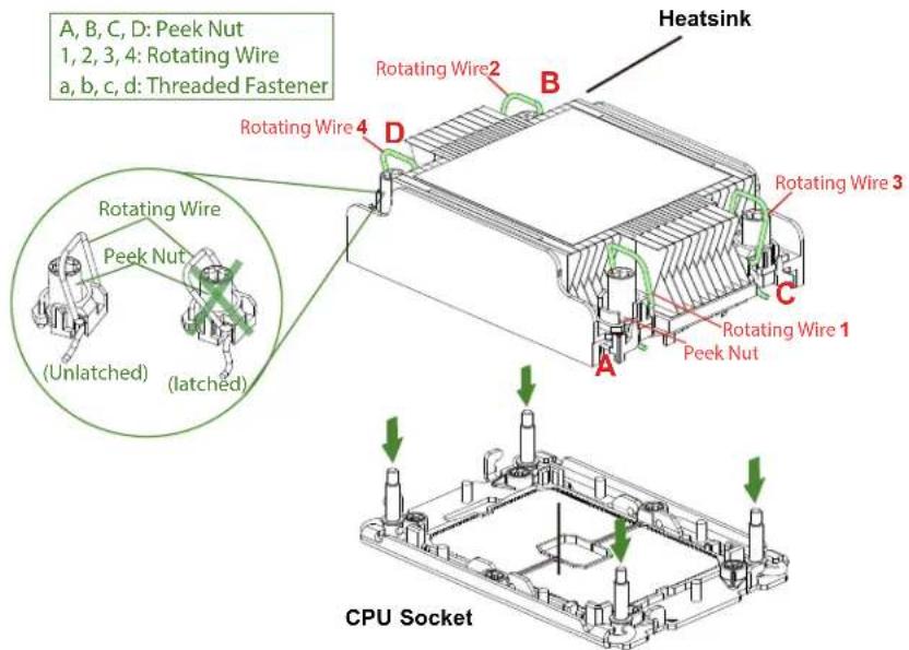
text_image
A, B, C, D: Peek Nut 1, 2, 3, 4: Rotating Wire a, b, c, d: Threaded Fastener Heatsink Rotating Wire 2 B Rotating Wire 4 D Rotating Wire 3 Rotating Wire 1 Peek Nut A CPU Socket Rotating Wire Peek Nut (Unlatched) (latched)- Check that the rotating wires (1, 2, 3, 4) are in the unlatched position as shown.

text_image
Unlatched State Rotating Wire Side View Top View Peek Nut-
Align nut A (next to the triangles and pin 1) on the heatsink with threaded fastener "a" on the CPU socket. Also align nuts B, C, D on the heatsink with threaded fasteners b, c, d on the CPU socket.
-
Gently place the heatsink on the CPU socket, making sure that each nut is properly aligned with its corresponding threaded fastener.
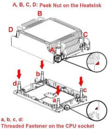
text_image
A, B, C, D: Peek Nut on the Heatsink B D C A b c a, b, c, d: Threaded Fastener on the CPU socket- Press all four rotating wires outward to latch the PHM onto the CPU socket.
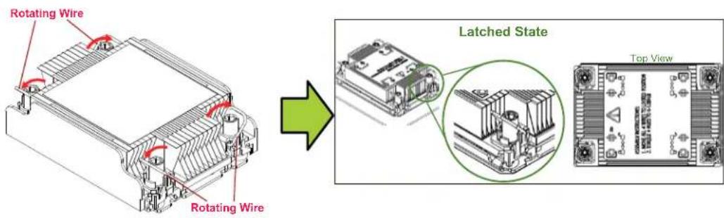
text_image
Rotating Wire Rotating Wire Latched State Top View- With a t30-bit screwdriver, tighten all PEEK nuts in the sequence of A, B, C, and D with even pressure no greater than 12 lbf-in.
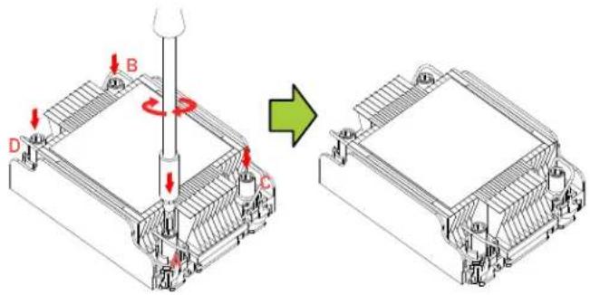
text_image
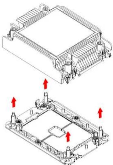
Technical diagram showing a mechanical assembly with labeled components A, B, C, D and directional arrows indicating motion or transformation.Removing the PHM from the CPU Socket
Be sure the system is shut down and all AC power cords are unplugged.
- Use a t30-bit screwdriver to loosen the four PEEK nuts on the heatsink in the sequence of A, B, C, and D.
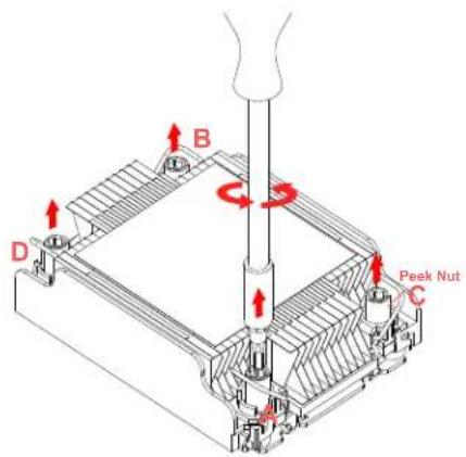
text_image
B D Peek Nut C- Press the four rotating wires inward to unlatch the PHM as shown below.

text_image
Unlatched State Rotating Wire Side View Peek Nut- Gently lift the PHM upward to remove it from the CPU socket.
natural_image
Technical line drawing of a mechanical housing with mounting holes and internal components, showing two views with red arrows indicating direction (no text or symbols present)Removing the Processor Carrier Assembly from the PHM
Detach the four plastic clips (a, b, c, d) on the processor carrier assembly from the four corners of the heatsink (A, B, C, D) as shown below, and lift off the processor carrier assembly.

Removing the Processor from the Carrier Assembly
Unlock the lever from its locked position and push it upwards to disengage the processor from the carrier as shown below right. Carefully remove the processor from the carrier.
Processor Carrier Assembly
natural_image
Isometric technical drawing of a mechanical component with no visible text or symbols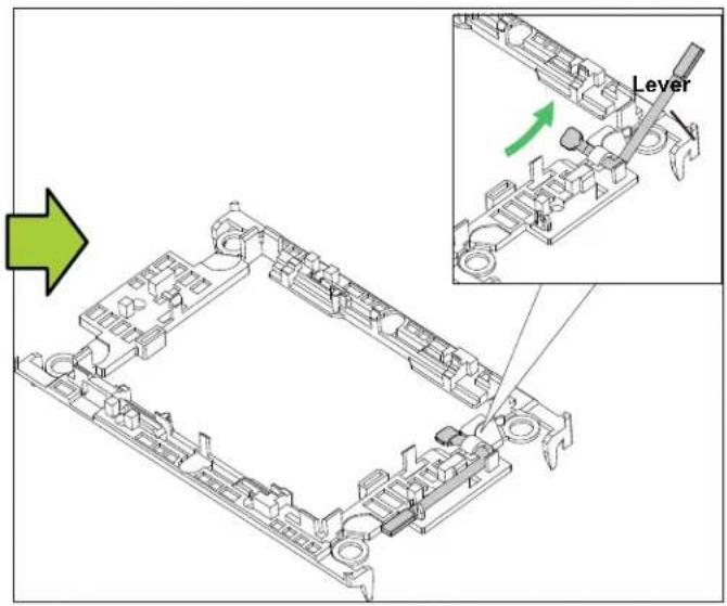
text_image
Technical diagram showing a mechanical assembly with an inset highlighting the lever mechanism, labeled 'Lever'Note: Handle the processor with care to avoid damage.

natural_image
Isometric technical diagram of a mechanical assembly with no visible text or symbols3.4 Memory
Memory Support
The X12SPW-TF supports up to 2048GB of ECC RDIMM/LRDIMM/LRDIMM 3DS with speeds of up to 3200MHz in eight slots. Refer to the tables below for the recommended DIMM population order and additional memory information. Use our Product Resources page.
| 1 CPU, 8-DIMM Slots | |
| Number of DIMMs Memory Population Sequence | |
| 1 DIMMA1 | |
| 2 DIMMA1 / DIMME1 | |
| 4 DIMMA1 / DIMME1 / DIMMC1 / DIMMG1 | |
| 6 DIMMA1 / DIMME1 / DIMMC1 / DIMMG1 / DIMMB1 / DIMMF1 | |
| 8 DIMMA1 / DIMME1 / DIMMC1 / DIMMG1 / DIMMB1 / DIMMF1 / DIMMD1 / DIMMH1 | |
| Type | Ranks Per DIMM and Data Width | DIMM Capacity (GB) | Speed (MT/s); Voltage (V); Slot Per Channel (SPC) and DIMM Per Channel (DPC)*Data below assumes 2 SPC unless otherwise noted. | |
| 1DPC | ||||
| 8 Gb 16 Gb 1.2V | ||||
| RDIMM | SRx8 8 GB 16 GB | 3200 | ||
| SRx4 16 GB 32 GB | ||||
| DRx8 16 GB 32 GB | ||||
| DRx4 32GB 64 GB | ||||
| RDIMM-3DS (4R/8R) x4 | 2H-64F GB 4H-128 GB | 2H-128 GB 4H 256 GB | 3200 | |
| LRDIMM | QRx4 | 64 GB | 128 GB | 3200 |
| LRDIMM-3DS | (4R/8R) X4 | 4H-128 GB | 2H-128 GB 4H-256 GB | 3200 |
Check the Supermicro website for possible updates to memory support.
General Guidelines for Optimizing Memory Performance
- For optimal performance, use DDR4 memory of the same type, size, and speed.
- Mixed DIMM speeds can be installed. However, all DIMMs will run at the speed of the slowest DIMM.
- The motherboard will support odd-numbered modules (one or three modules installed). However, to achieve the best memory performance, a balanced memory population is recommended.
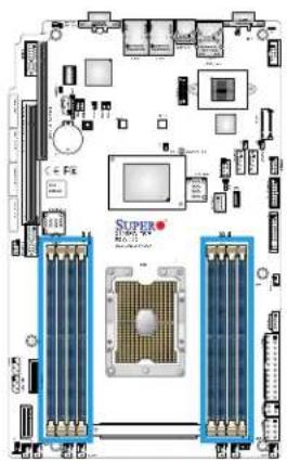
DIMM Installation
- Insert the desired number of DIMMs into the memory slots based on the recommended DIMM population table.
- Push the release tabs outwards on both ends of the DIMM slot to unlock it.
- Align the key of the DIMM module with the receptive point on the memory slot.
- Align the notches on both ends of the module against the receptive points on the ends of the slot.
- Press the ends of the module straight down into the slot until the module snaps into place.
- Press the release tabs to the lock positions to secure the DIMM module into the slot.
DIMM Removal
Press both release tabs on the ends of the DIMM module to unlock it. Once the DIMM module is loosened, remove it from the memory slot.
natural_image
Top-down schematic of a computer motherboard showing CPU socket, RAM slots, and drive components (no readable text or labels)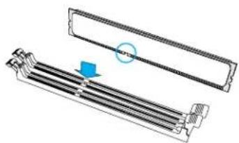
natural_image
Technical illustration of a mechanical component with a circular arrow indicating rotation (no text or symbols present)
text_image
Notches Release Tabs
text_image
Press both ends straight down into the memory slot.3.5 Motherboard Battery
The motherboard uses non-volatile memory to retain system information when system power is removed. This memory is powered by a lithium battery residing on the motherboard.
Replacing the Battery
Begin by removing power from the system.
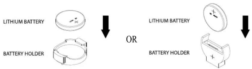
- Push aside the small clamp that covers the edge of the battery. When the battery is released, lift it out of the holder.
- To insert a new battery, slide one edge under the lip of the holder with the positive (+) side facing up. Then push the other side down until the clamp snaps over it.
Note: Handle used batteries carefully. Do not damage the battery in any way; a damaged battery may release hazardous materials into the environment. Do not discard a used battery in the garbage or a public landfill. Please comply with the regulations set up by your local hazardous waste management agency to dispose of your used battery properly.
text_image
LITHIUM BATTERY BATTERY HOLDER OR LITHIUM BATTERY BATTERY HOLDERFigure 3-6. Installing the Onboard Battery
Warning: There is a danger of explosion if the onboard battery is installed upside down (which reverses its polarities). This battery must be replaced only with the same or an equivalent type recommended by the manufacturer (CR2032).
3.6 Storage Drives
The system supports up to four fixed 2.5" SATA storage drives that are installed to a drive cage and then inserted into the chassis. For compatible storage drives, see the SYS-E403-12P-FN2T system page.
Note: Enterprise level hard disk drives are recommended for use in Supermicro chassis and servers. For information on recommended HDDs, visit the Supermicro website product pages.
Hard Drives
Your server may or may not have come with fixed internal hard drives installed. Up to four 2.5" hard drives are supported by the chassis.
Installing Drives
The system supports two SATA3 drives by default. The motherboard should be installed before installing the drives.
-
Remove the system power as described in section 2.1 and remove the chassis cover.
-
Remove the two screws that secure the drive cage to the chassis, as shown.
- Pull the drive cage upwards using the provided plastic handles.
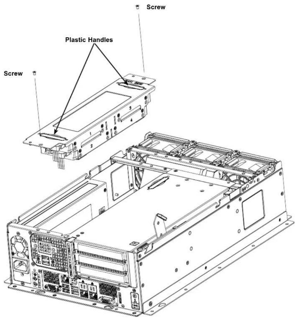
text_image
Screw Plastic Handles ScrewFigure 3-7. Preparing to Install the Storage Drives
- Place the drives inside the cage, stacked up to two units on each end, then secure them inside the drive bays with the included screws, as shown below.

natural_image
Exploded view diagram of a device showing internal components and assembly (no text or labels)Figure 3-8. Installing the Drives
- Connect the drive data and power cables.
- Secure the hard drive cage back to the chassis with the screws previously set aside.
- Attach the cables to the appropriate motherboard connectors.
- Reinstall the chassis cover and power up the system.
M.2 Solid State Drives
An M.2 solid state drive (SSD) can be installed on the motherboard, supporting PCIe and SATA.
Two lengths are supported, 80mm or 110mm. For each length, there is a hole in the motherboard for a plastic standoff.
Installing an M.2 SSD
Caution: Use industry-standard anti-static equipment, such as gloves or a wrist strap, and follow precautions to avoid damage caused by ESD.
Locate the M.2 slot on the motherboard and the standoff holes for each possible length card, MH10 and MH11. There is a plastic standoff in one of the holes. If necessary move the plastic standoff to the correct hole. Slide the M.2 SSD into the socket, then secure it by pushing the plug into the standoff.
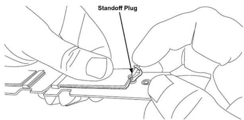
text_image
Standoff PlugFigure 3-9. Inserting the Standoff Plug
(Note: Your installation may look different, but the standoff functions the same.)
3.7 PCI Expansion Cards
The system supports up to three PCIe cards on a riser card with three PCIe 4.0 x16 slots. Use the jumper on the riser card, JSEL1, to configure.
The system supports full height or low profile expansion cards, although you must modify the air shroud when using full height.
Installing or Replacing the Expansion Card Module
- Power down the system as described in Section 3.1 and remove the chassis cover.
- Remove the screws, as shown in the diagram on the following page.
- Pull the locking lever up to release the expansion card module.
- Gently pull the expansion card module upward with the aid of the plastic handle. There are two cables connecting the motherboard and the expansion card module, so take care not to jerk the cables.
- If needed, detach the cables for convenient operation.
- In the removed expansion card module, install expansion cards. For full height cards, install first in the top-most slot, then the middle, and then the bottom slot. Note that you must also modify the main air shroud to fit full height cards.
- If the cables have been detached, reconnect the cables.
- Replace the expansion card module and secure it with two screws.
- Reinstall the chassis top cover, reconnect the AC power cord, and power up the system.
Caution: If installing three NVIDIA T4 GPUs in the expansion card module, the processor must consume less than or equal to 165W TDP.

text_image
Screws Plastic Handle Expansion Card Module Locking LeverFigure 3-10. Expansion Card Module
3.8 System Cooling
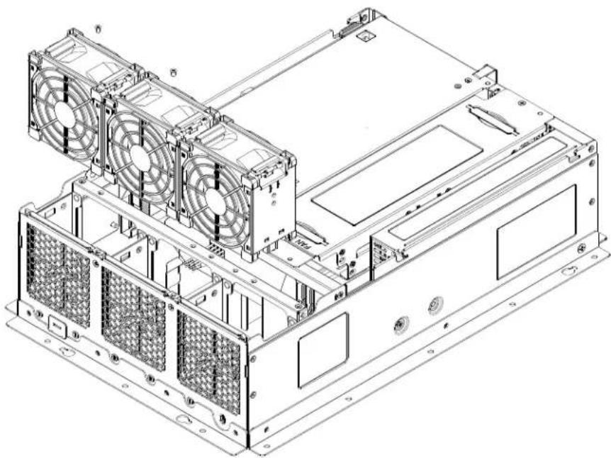
The SuperServer SYS-E403-12P-FN2T includes three replaceable 8-cm x 3.8-cm fans and one air shroud to direct air flow. Make sure the chassis top cover makes a good seal so the cooling air circulates properly through the chassis.
Caution: Since the system continues to draw a small amount of power in standby mode (and fans are off), there is a potential for overheating if the system is idle for a long time. In this situation, there is no warning from the overheat/fan fail LED.
Fans
Three 8-cm x 3.8-cm fans provide the cooling for the system. These fans circulate air through the chassis as a means of lowering the chassis internal temperature. The fans can adjust their speed according to the heat level sensed in the system, which results in more efficient and quieter fan operation. Fan speed is controlled by IPMI. Each fan has its own separate tachometer.

natural_image
Interior view of a server rack with labeled components (no text or symbols on the main body)Figure 3-11. Fan Positions
Replacing Fans
If a fan fails, the remaining fans will ramp up to full speed, the overheat/fan fail LED on the control panel will blink on and off. Replace any failed fan at your earliest convenience with the same type and model.
- Power down the system and remove the AC power cord and the chassis cover.
-
Remove the old fan from the fan brace by pressing the fan latch and pulling it up.
-
Slide the new fan into the fan brace until the fan latch snaps into the notch and you hear a click sound.
- Reinstall the chassis top cover, reconnect the AC power cord, and power up the system.
natural_image
Technical line drawing of a computer tower with multiple fans and drive bays (no text or labels)Figure 3-12. Replacing the System Fans
Air Shrouds
The SYS-E403-12P-FN2T supports an air shroud that concentrates airflow to maximize fan efficiency. It does not require screws to install.
Replacing the Air Shroud
- If you are installing full height PCIe expansion cards, you must cut one, two, or three sections of the shroud to create space for the cards.
- Remove the chassis cross bracket by removing the screw from each side of the chassis.
- Place the air shroud. The small rectangular portion covers the DIMMA1/DIMMB1/ DIMMC1 memory modules.
- Replace the chassis cross bracket.
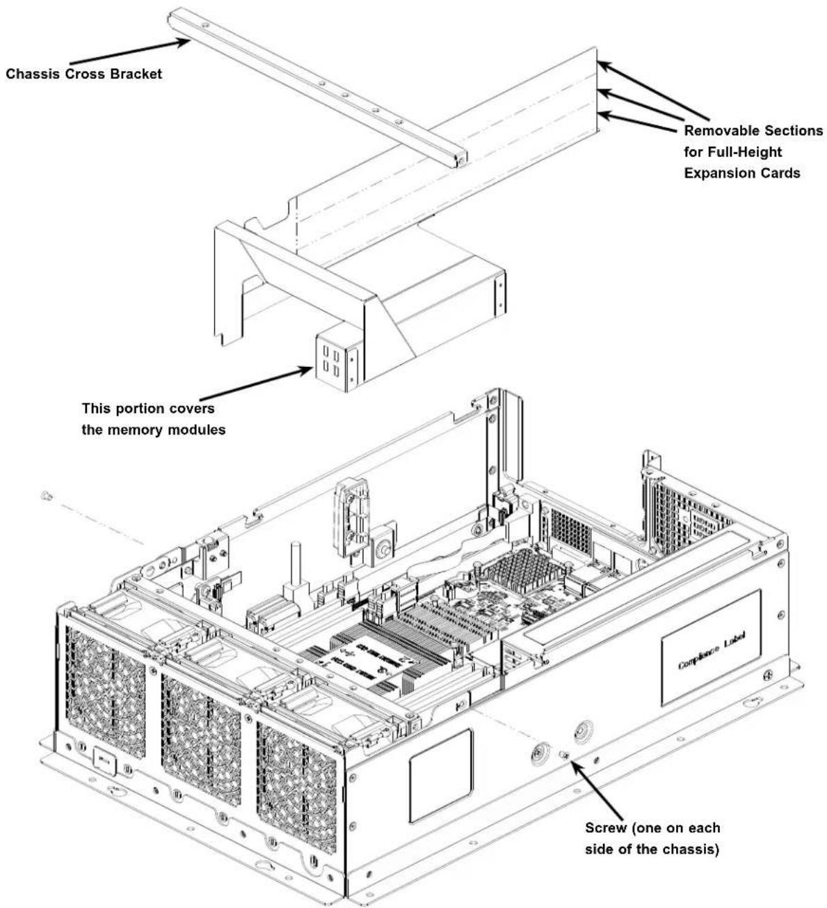
text_image
Chassis Cross Bracket Removable Sections for Full-Height Expansion Cards This portion covers the memory modules Screw (one on each side of the chassis)Figure 3-13. Installing the Memory Air Shroud
Checking the Server Air Flow
- Make sure there are no objects to obstruct airflow in and out of the server.
- Use only recommended server parts.
- Make sure no wires or foreign objects obstruct air flow through the chassis. Pull all excess cabling out of the airflow path or use shorter cables.
The control panel LEDs display system heat status. See “Control Panel” in Chapter 1 for details.
Overheating
There are several possible responses if the system overheats.
If the server overheats:
- Use the overheat/fan fail LED to determine the nature of the overheating condition.
- Confirm that the chassis covers are installed properly.
- Make sure all fans are present and operating normally.
- Check the routing of the cables.
- Verify that the air shroud is installed properly.
3.9 Power Supply
The CSE-E403iF-000NBP chassis has one 600W AC power supply. The power supply can operate at a 100-240VAC input range. New units can be ordered directly from Supermicro or authorized distributors.
Power Supply Failure
The SYS-E403-12P-FN2T includes an internal power supply that can be replaced.
Replacing the Power Supply
- Disconnect the power cord from the power strip or outlet.
- Remove the top cover.
- To access the motherboard, remove the expansion card module and the hard drives as described previously. Make sure to disconnect the extension cables from the motherboard and the power supply.
- With access to the motherboard, remove the ATX power connection (JPWR1) and the 8-pin power connection (JPV1).
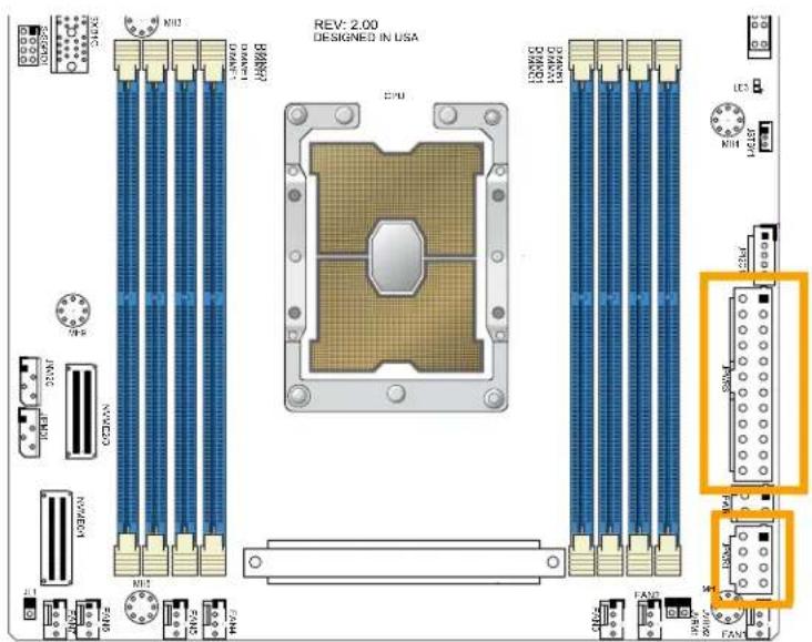
Figure 3-14. Removing the ATX and 8-pin Connections
-
Remove three screws on the chassis as shown in Figure 3-15 and set them aside.
-
Lift the power supply out of the chassis.
-
Place a new power supply into the chassis with the fan at the top front. Install the three screws.
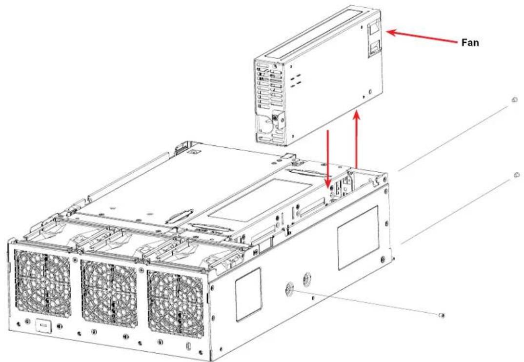
text_image
FanFigure 3-15. Removing the Power Supply
- Reconnect the ATX and 8-pin power connection to the motherboard.
- If necessary reconnect the expansion card power supply and replace the expansion card module.
- Reconnect the hard drive data and power extension cables and replace the hard drive cage.
- Replace the chassis top cover.
- Reconnect the power supply cord to the power supply inlet and the power source.
Note: The figure above is intended to show the power supply locations only. The chassis and serverboard may differ from those found in the SYS-E403-12P-FN2T.
3.10 Cable Routing Diagram
Refer to the diagram below for a representation of how the main cables are routed throughout the system. When disconnecting cables to add or replace components, refer to this diagram when adding or replacing components so you can reroute them in the same manner. Proper cable routing is important in maintaining proper airflow through the system.
USB 3.0 Cable
CBL-CUSB-0832
Online Cable Matrix
natural_image
Interior view of a computer motherboard showing CPU socket, RAM slots, and wiring (no readable text or symbols)Figure 3-16. Cable Routing Diagram
Chapter 4
Motherboard Connections
This section describes the connections on the motherboard and provides pinout definitions. Note that depending on how the system is configured, not all connections are required. The LEDs on the motherboard are also described here. A motherboard layout indicating component locations may be found in Chapter 1. More detail can be found in the Motherboard Manual. Please review the Safety Precautions in Appendix A before installing or removing components.
4.1 Power Connections
Two power connections supply the motherboard and several more supply for onboard devices.
ATX Power Supply Connector
The 24-pin power supply connector (JPWR3) meets the ATX SSI EPS 12V specification. You must also connect the 8-pin (JPWR1) and 4-pin (JPWR2) processor power connector to the power supply.
| ATX Power 24-pin Connector Pin Definitions | ||
| Pin# Definition Pin# Definition | ||
| 13 +3.3V 1 +3.3V | ||
| 14 -12V 2 +3.3V | ||
| 15 Ground 3 Ground | ||
| 16 PS_ON 4 +5V | ||
| 17 Ground 5 Ground | ||
| 18 Ground 6 +5V | ||
| 19 Ground 7 Ground | ||
| 20 Res (NC) 8 PWR_OK | ||
| 21 +5V 9 5VSB | ||
| 22 +5V 10 +12V | ||
| 23 +5V 11 +12V | ||
| 24 Ground 12 +3.3V | ||
Required Connection
8-Pin Power Connector
JPWR1 is an 8-pin 12V DC power input for the CPU that must be connected to the power supply. Refer to the table below for pin definitions.
| 8-pin PowerPin Definitions | |
| Pin# Definition | |
| 1 - 4 Ground | |
| 5 - 8 P12V (12V Power) |
Required Connection
4-Pin Power Connector
JPWR2 is an 4-pin 12V DC power input for the CPU that must be connected to the power supply. Refer to the table below for pin definitions.
| 4-pin PowerPin Definitions |
| Pin# Definition |
| 1 - 2 Ground |
| 3 - 4 P12V (12V Power) |
Required Connection
Important: To provide adequate power supply to the motherboard, be sure to connect the 24-pin ATX PWR, the 8-pin PWR, and 4-pin PWR connectors to the power supply. Failure to do so may void the manufacturer warranty on your power supply and motherboard.
4.2 Headers and Connectors
Headers
Fan Headers
There are seven 4-pin fan headers (FAN1 - FAN7) on the motherboard. All these 4-pin fan headers are backwards compatible with the traditional 3-pin fans. However, fan speed control is available for 4-pin fans only by the Thermal Management via the IPMI 2.0 interface. Refer to the table below for pin definitions.
| Fan HeaderPin Definitions |
| Pin# Definition |
| 1 Ground (Black) |
| 2 2.5A/+12V (Red) |
| 3 Tachometer |
| 4 PWM_Control |
SGPIO Headers
There is one Serial Link General Purpose Input/Output (S-SGPIO1) header located on the motherboard. S-SGPIO is for sSATA use. Refer to the tables below for pin definitions.
| SGPIO HeaderPin Definitions | ||
| Pin# Definition Pin# Definition | ||
| 1 NC 2 NC | ||
| 3 Ground 4 Data | ||
| 5 Load 6 Ground | ||
| 7 Clock 8 NC | ||
NC = No Connection
Disk-On-Module Power Connector
Two power connectors for SATA DOM (Disk-On-Module) devices are located at JSD1 and JSD2. Connect appropriate cables here to provide power support for your Serial Link DOM devices.
| DOM Power Pin Definitions | |
| Pin# Definition | |
| 1 5V | |
| 2 Ground | |
| 3 Ground | |
TPM/Port 80 Header
A Trusted Platform Module (TPM)/Port 80 header is located at JTPM1 to provide TPM support and Port 80 connection. Use this header to enhance system performance and data security. Refer to the table below for pin definitions. Please go to the following link for more information on the TPM: http://www.supermicro.com/manuals/other/TPM.pdf.
| Trusted Platform Module HeaderPin Definitions | ||
| Pin# Definition Pin# Definition | ||
| 1 +3.3V 2 SPI_CS# | ||
| 3 RESET# 4 SPI_MISO | ||
| 5 SPI_CLK 6 GND | ||
| 7 SPI_MOSI 8 NC | ||
| 9 +3.3V Stdby 10 SPI_IRQ# | ||
Standby Power
The Standby Power header is located at JSTBY1 on the motherboard. You must have a card with a Standby Power connector and a cable to use this feature. Refer to the table below for pin definitions.
| Standby Power Pin Definitions | |
| Pin# Definition | |
| 1 +5V | Standby |
| 2 Ground | |
| 3 No Connection | |
4-pin BMC External I²C Header
A System Management Bus header for IPMI 2.0 is located at JIPMB1. Connect the appropriate cable here to use the IPMB I ^2 C connection on your system. Refer to the table below for pin definitions.
| External I2C Header Pin Definitions | |
| Pin# | Definition |
| 1 | Data |
| 2 | Ground |
| 3 | Clock |
| 4 | P3V3 STBY |
Chassis Intrusion
A Chassis Intrusion header is located at JL1 on the motherboard. Attach the appropriate cable from the chassis to inform you of a chassis intrusion when the chassis is opened. Refer to the table below for pin definitions.
| Chassis Intrusion Pin Definitions | |
| Pin# Definition | |
| 1 Intrusion Input | |
| 2 Ground |
NVMe I²C Header
Connector JNVI ^2 C1 is a management header for the Supermicro AOC NVMe PCIe peripheral cards. Please connect the I ^2 C cable to this connector.
NC-SI Header for IPMI Support
A Network-Controller Sideband Interface (NC-SI) header is located at JNCSI1 on the motherboard. For remote management, connect the appropriate cable from this header to an add-on card to provide the out-of-band (sideband) connection between the onboard Baseboard Management Controller (BMC) and a Network Interface Controller (NIC). For the network sideband interface to work properly, you will need to use a NIC add-on card that supports NC-SI and must use a special cable. Please contact Supermicro at www.supermicro.com to purchase the cable for this header. Refer to the table below for pin definitions.
| NCSIPin Definition | |||
| Pin# Definition Pin# Definition | |||
| 1 NCSI | Clock 2 Ground | ||
| 3 NCSI | CRS_DV 4 Ground | ||
| 5 NCSI | RX_D0 6 Ground | ||
| 7 NCSI | RX_D1 8 Ground | ||
| 9 NCSI | TX_D0 10 Ground | ||
| 11 NCSI | TX_D1 12 Ground | ||
| 13 NCSI | TX_EN 14 NCSI | Present | N |
| 15 JNCSI | SRB_IN 16 JNCSI | ARB | OUT |
| 17 P5V | AUX 18 P5V_AUX | ||
| 19 P5V | AUX 20 P5V_AUX | ||
| 21 P5V | AUX 22 Test Point | ||
BMC External I²C Header
A System Management Bus header for IPMI 2.0 is located at JI2C_EXP1. Connect the appropriate cable here to use the IPMI connection on your system. Refer to the table below for pin definitions.
| External I2C Header Pin Definitions | |
| Pin# | Definition |
| 1 | Data |
| 2 | Ground |
| 3 | Clock |
| 4 | P3V3 STBY |
Power SMB (I²C) Header
The Power System Management Bus (I²C) connector JPI²C1) monitors the power supply, fan, and system temperatures. Refer to the table below for pin definitions.
| Power SMB HeaderPin Definitions |
| Pin# Definition |
| 1 Clock |
| 2 Data |
| 3 PMBUS_Alert |
| 4 Ground |
| 5 +3.3V |
SATA Ports
Eight SATA 3.0 ports are located on the motherboard and supported by the chipset. These SATA ports support RAID 0, 1, 5, and 10. In addition, there are also two S-SATA ports (S-SATA0, S-SATA1) that include SATA DOM power.
Note: For more information on the SATA HostRAID configuration, please refer to the Intel SATA HostRAID user's guide posted on our website at http://www.supermicro.com.
M.2 Slot
The motherboard has one M.2 slot. M.2 was formerly known as Next Generation Form Factor (NGFF) and serves to replace mini PCIe. M.2 allows for a variety of card sizes, increased functionality, and spatial efficiency. The M.2 socket on the motherboard supports PCIe 3.0 x4/SATA3 SSD cards in the 2280 and 22110 form factors.
Intel RAID Key Header
The JRK1 header allows you to enable RAID functions for NVMe connections. Refer to the table below for pin definitions.
| Intel RAID Key HeaderPin Definitions | |
| Pin# Definition | |
| 1 GND | |
| 2 PU 3.8V Stdby | |
| 3 | GND |
| 4 | PCH RAID KEY |
NVM Express Connections
There are two Slimline SAS connectors located on the motherboard to support two PCIe 4.0 x4 NVMe connections. This connector provides high-speed and low-latency connections directly from the CPU to NVMe Solid State (SSD) drives. This greatly increases SSD data-throughput performance and significantly reduces PCIe latency by simplifying driver/software requirements resulting from direct PCIe interface from the CPU to the NVMe SSD drives.
| NVME0/1 Connector Pin Definitions | ||
| Pin# Signal Pin# Signal | ||
| 1 GND | 20 RX4P | |
| 2 RX0P | 21 RX4N | |
| 3 RX0N | 22 GND | |
| 4 GND | 23 RX5P | |
| 5 RX1P | 24 RX5N | |
| 6 RX1N | 25 GND | |
| 7 GND | 26 SB7B | |
| 8 SB7A | 27 SB4B | |
| 9 SB4A | 28 GND | |
| 10 GND | 29 SBB+ | |
| 11 SBA+ | 30 SBB- | |
| 12 | SBA- 31 GND | |
| 13 GND | 32 RX6P | |
| 14 R2XP | 33 RX6N | |
| 15 RX2N | 34 GND | |
| 16 GND | 35 RX7P | |
| 17 RX3P | 36 RX7N | |
| 18 RX3N | 37 GND | |
| 19 GND | ||
4.3 Input/Output Ports
Rear I/O Ports
See the figure below for the locations and descriptions of the I/O ports on the rear of the motherboard.

text_image
Diagram showing six labeled network ports (1–6) with corresponding logos and numbers, likely representing server or network equipment.Figure 4-1. Rear I/O Ports
| Rear I/O Ports | |
| # Description # Description | |
| 1 COM Port 1 6 USB5 (3.2 Gen 1) | |
| 2 Dedicated IPMI LAN 7 LAN1 | |
| 3 USB0 (2.0) 8 LAN2 | |
| 4 USB1 (2.0) 9 VGA Port | |
| 5 USB4 (3.2 Gen 1) |
4.4 Jumpers
Explanation of Jumpers
To modify the operation of the motherboard, jumpers can be used to choose between optional settings. Jumpers create shorts between two pins to change the function of the connector. Pin 1 is identified with a square solder pad on the printed circuit board. See the diagram below for an example of jumping pins 1 and 2. Refer to the motherboard layout page for jumper locations.
Note: On two-pin jumpers, "Closed" means the jumper is on and "Open" means the jumper is off the pins.

text_image
Connector Pins Jumper Setting 3 2 1 ● ● ■ 3 2 1CMOS Clear
JBT1 is used to clear CMOS, which will also clear any passwords. Instead of pins, this jumper consists of contact pads to prevent accidentally clearing the contents of CMOS.
To Clear CMOS
- Power down the system and unplug the power cord(s).
- Remove the cover of the chassis to access the motherboard.
- Remove the onboard battery from the motherboard.
- Short the CMOS pads with a metal object such as a small screwdriver for at least four seconds.
- Remove the screwdriver (or shorting device).
- Replace the cover, reconnect the power cord(s), and power on the system.
Note: Clearing CMOS will also clear all passwords.
Do not use the PW_ON connector to clear CMOS.

JBT1 contact pads
LAN Port Enable/Disable
Use JPL3 to enable or disable LAN ports 1 and 2.
| LAN Port Enable/Disable Jumper Settings | |
| Jumper Setting Definition | |
| Pins 1-2 Enabled | |
| Pins 2-3 Disabled | |
ME Manufacturing Mode
Close pins 2-3 of jumper JPME1 to bypass SPI flash security and force the system to operate in the manufacturing mode, which will allow the user to flash the system firmware from a host server for system setting modifications. Refer to the table below for jumper settings. The default setting is Normal.
| Manufacturing ModeJumper Settings | |
| Jumper Setting Definition | |
| Pins 1-2 Normal | |
| Pins 2-3 Manufacturing Mode | |
4.5 LED Indicators
LAN LEDs
Two LAN ports (LAN 1 and LAN 2) are located on the I/O back panel of the motherboard. Each Ethernet LAN port has two LEDs. The green LED indicates activity, while the other Link LED may be green, amber, or off to indicate the speed of the connection. Refer to the tables below for more information.
| LAN1/2 Activity LED (Right)LED State | ||
| Color Status Definition | ||
| Green Flashing Active | ||
| LAN1/2 Link LED (Left)LED State | |
| LED Color Definition | |
| Green 10Gbps | |
| Yellow/Amber 1Gbps | |
IPMI LAN LEDs
In addition to LAN1 and LAN2, an IPMI LAN is also located on the I/O back panel. The amber LED on the right indicates activity, while the green LED on the left indicates the speed of the connection. Refer to the table below for more information.
| IPMI LAN LEDs | ||
| Color/State Definition | ||
| Link (left) | Green: Solid Amber: Solid | 100 Mbps 1Gbps |
| Activity (Right) Amber: Blinking Active | ||
Unit ID LED
A rear UID LED indicator (UID-LED) is located near the UID switch on the I/O back panel. This UID indicator provides easy identification of a system unit that may need service.
| UID LEDLED Indicator | |
| LED Color Definition | |
| Blue: On Unit | Identified |
BMC Heartbeat LED
A BMC Heartbeat LED is I coated at LEDBMC on the motherboard. When LEDBMC is blinking, the BMC is functioning normally. Refer to the table below for more information.
| BMC Heartbeat LED Indicator |
| LED Color Definition |
| Green: Blinking BMC Normal |
Power LED
The Power LED is located at LE3 on the motherboard. When this LED is on, the system is on. Be sure to turn off the system and unplug the power cord before removing or installing components. Refer to the table below for more information.
| Onboard Power LED Indicator | |
| LED Color Definition | |
| Off | System Off(power cable not connected) |
| Green System | On |
M.2 LED
An M.2 LED is located at LE4 on the motherboard. When LE4 is blinking, M.2 functions normally. Refer to the table below for more information.
| M.2 LED State | |
| LED Color Definition | |
| Green: Blinking Device Working |
Chapter 5
Software
After the hardware has been installed, you can install the Operating System (OS), configure RAID settings, and install the drivers.
5.1 Microsoft Windows OS Installation
If you will be using RAID, you must configure RAID settings before installing the Windows OS and the RAID driver. Refer to the RAID Configuration User Guides posted on our website at www.supermicro.com/support/manuals.
Installing the OS
- Create a method to access the MS Windows installation ISO file. That might be a DVD, perhaps using an external USB/SATA DVD drive, or a USB flash drive, or the BMC KVM console.
- Retrieve the proper RST/RSTe driver. Go to the Supermicro web page for your motherboard and click on "Download the Latest Drivers and Utilities", select the proper driver, and copy it to a USB flash drive.
- Boot from a bootable device with Windows OS installation. You can see a bootable device list by pressing [F11] during the system startup.
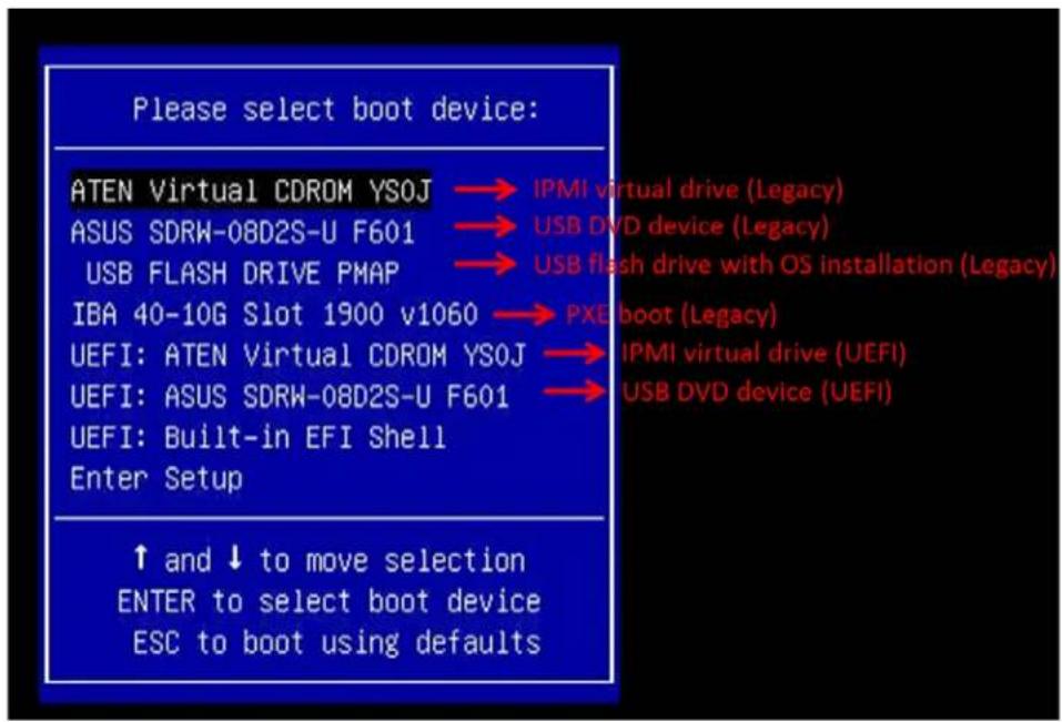
text_image
Please select boot device: ATEN Virtual CDROM YSOJ → IPMI virtual drive (Legacy) ASUS SDRW-08D2S-U F601 → USB DVD device (Legacy) USB FLASH DRIVE PMAP → USB flash drive with OS installation (Legacy) IBA 40-10G Slot 1900 v1060 → PXE boot (Legacy) UEFI: ATEN Virtual CDROM YSOJ → IPMI virtual drive (UEFI) UEFI: ASUS SDRW-08D2S-U F601 → USB DVD device (UEFI) UEFI: Built-in EFI Shell Enter Setup ↑ and ↓ to move selection ENTER to select boot device ESC to boot using defaultsFigure 5-1. Select Boot Device
- During Windows Setup, continue to the dialog where you select the drives on which to install Windows. If the disk you want to use is not listed, click on "Load driver" link at the bottom left corner.
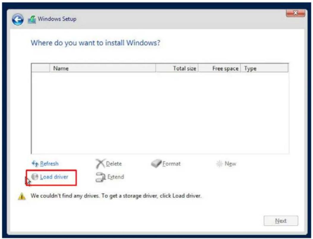
text_image
Where do you want to install Windows? Name Total size Free space Type Refresh Delete Format New Load driver Extend We couldn't find any drives. To get a storage driver, click Load driver. NextFigure 5-2. Load Driver Link
To load the driver, browse the USB flash drive for the proper driver files.
- For RAID, choose the SATA/sSATA RAID driver indicated, then choose the storage drive on which you want to install it.
-
For non-RAID, choose the SATA/sSATA AHCI driver indicated, then choose the storage drive on which you want to install it.
-
Once all devices are specified, continue with the installation.
- After the Windows OS installation has completed, the system will automatically reboot multiple times.
5.2 Driver Installation
The Supermicro website contains drivers and utilities for your system at https://www.supermicro.com/wdl. Some of these must be installed, such as the chipset driver.
After accessing the website, go into the CDR_Images (in the parent directory of the above link) and locate the ISO file for your motherboard. Download this file to a USB flash drive or a DVD. (You may also use a utility to extract the ISO file if preferred.)
Another option is to go to the Supermicro website at http://www.supermicro.com/products/. Find the product page for your motherboard, and "Download the Latest Drivers and Utilities". Insert the flash drive or disk and the screenshot shown below should appear.
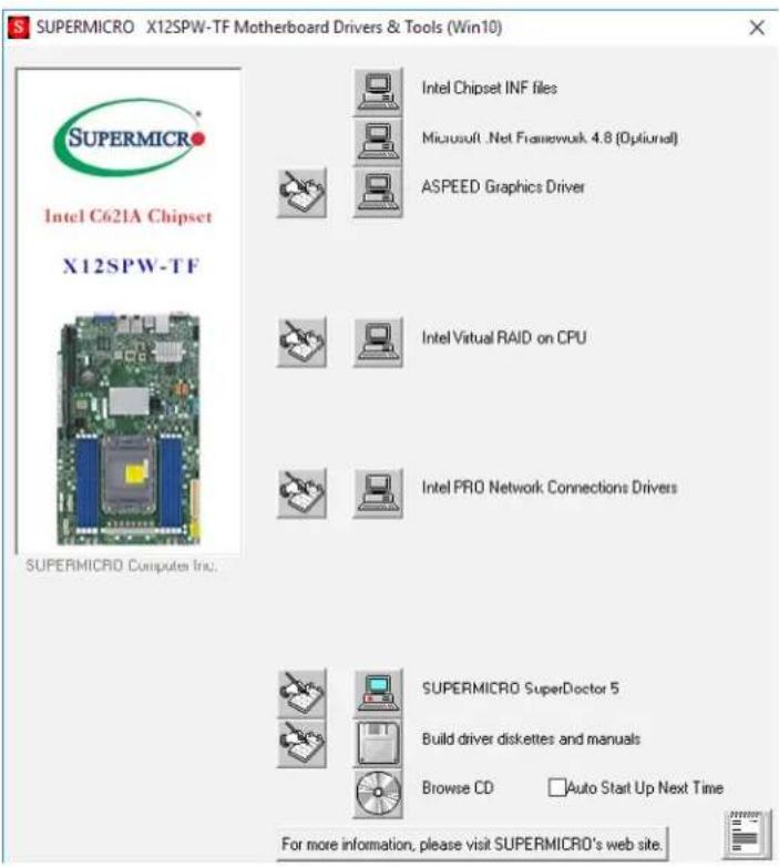
text_image
SUPERMICRO X12SPW-TF Motherboard Drivers & Tools (Win10) Intel C621A Chipset X12SPW-TF SUPERMICRO Computers Inc. Intel Chipset INF files Microsoft .Net Framework 4.8 (Optional) ASPEED Graphics Driver Intel Virtual RAID on CPU Intel PRO Network Connections Drivers SUPERMICRO SuperDoctor 5 Build driver diskettes and manuals Browse CD Auto Start Up Next Time For more information, please visit SUPERMICRO's web site.Figure 5-3. Driver & Tool Installation Screen
Note: Click the icons showing a hand writing on paper to view the readme files for each item. Click the computer icons to the right of these items to install each item (from top to the bottom) one at a time. After installing each item, you must re-boot the system before moving on to the next item on the list. The bottom icon with a CD on it allows you to view the entire contents.
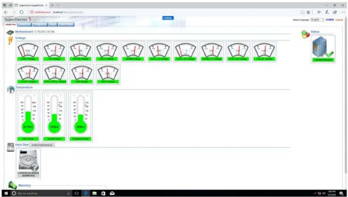
5.3 SuperDoctor® 5
The Supermicro SuperDoctor 5 is a program that functions in a command-line or web-based interface for Windows and Linux operating systems. The program monitors such system health information as CPU temperature, system voltages, system power consumption, and fan speed, and provides alerts via email or Simple Network Management Protocol (SNMP).
SuperDoctor 5 comes in local and remote management versions and can be used with Nagios to maximize your system monitoring needs. With SuperDoctor 5 Management Server (SSM Server), you can remotely control power on/off and reset chassis intrusion for multiple systems with SuperDoctor 5 or BMC. SuperDoctor 5 Management Server monitors HTTP, FTP, and SMTP services to optimize the efficiency of your operation.
SuperDoctor® Manual and Resources
text_image
SuperMicro SuperDocs Certificate error location (MIA) (SuperDoctor) Loading Motherboard: C70350-CB-ML Voltage Temperature Hard Disk install Instruments Memory Select language: English / AEMINE / Install Status Chassis Insettes SuperMicro SuperDocs 1.0V 1.0V 1.0V 1.0V 1.0V 1.0V 1.0V 1.0V 1.0V 1.0V 1.0V 1.0V 1.0V 1.0V 1.0V 1.0V 1.0V 1.0V 1.0V 1.0V 1.0V CPU Time 24/196.2 32/89.6 29/42.2 SuperMicro Superdo 2.0V 1.0V 1.0V 1.0V 1.0V 1.0V 1.0V 1.0V 1.0V 1.0V 1.0V 2.0V 1.0V 1.0V 1.0V 1.0V 1.0V 1.0V 1.0V 1.0V 2.0V 1.0V 1.0V 1.0V 1.0V 1.0V 1.0V 1.0V 2.0V 1.0V 1.0V 1.0V 1.0V 1.0V 1.0V 2.0V 1.0V 1.0V 1.0V 1.0V 1.0V 1.0V 2.0V 1.0V 1.0V 1.0V 1.0V 1.0V 2.0V 1.0V 1.0V 1.0V 1.0V 1.0V 2.0V 1.0V 1.0V 1.0V 1.0V 1.0V 2.0V 1.0V 24/27/28/29/30/31/32/33/34/35/36/37/38/39/40/41/42/43/44/45/46/47/48/49/50/51/52/53/54/55/56/57/58/59/60/61/62/63/64/65/66/67/68/69/70/71/72/73/74/75/76/77/78/79/80/81/82/83/84/85/86/87/88/89/90/91/92/93/94/95/96/97/98/99/100/101/102/103/104/105/106/107/108/109/110/111/112/113/114/115/116/117/118/119/120/121/122/123/124/125/126/127/128/129/130/131/132/133/134/135/136/137/138/139/140/141/142/143/144/145/146/147/148/149/150/151/152/153/154/155/156/157/158/159/160Figure 5-4. SuperDoctor 5 Interface Display Screen (Health Information)
5.4 BMC
The X12SPW-TF provides remote access, monitoring, and management through the baseboard management controller (BMC) and other management controllers distributed among different system modules. There are several BIOS settings that are related to BMC.
For general documentation and information on BMC, visit our website at: https://www.supermicro.com/en/solutions/management-software/bmc-resources
BMC ADMIN User Password
For security, each system is assigned a unique default BMC password for the ADMIN user. This can be found on a sticker on the chassis and a sticker on the motherboard. The sticker also displays the BMC MAC address.

text_image
BMC AC1F6BC PWD SUOKJFigure 5-5. BMC Password Label
See Chapter 1 for the locations of the labels.
Chapter 6
Optional Components
This chapter describes optional system components and installation procedures.
6.1 Optional Parts List
| Optional Parts List | ||
| Description Part Number Quantity | ||
| GPU auxiliary power cable CBL-PWEX-1041 1 | ||
6.2 GPU Auxiliary Power Cable
The CBL-PWEX-1041 cable connects from PWS for extra power to high performance GPU cards.
Chapter 7
Troubleshooting and Support
7.1 Information Resources
Website
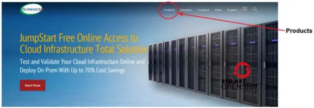
A great deal of information is available on the Supermicro website, supermicro.com.
text_image
SuperMPC JumpStart Free Online Access to Cloud Infrastructure Total Solution Test and Validate Your Cloud Infrastructure Online and Deploy On-Prem With Up to 70% Cost Savings Start Now Products Red Hat OPENSHIPFigure 7-1. Supermicro Website
- Specifications for servers and other hardware are available by clicking on Products.
- The Support option offers downloads (manuals, BIOS/IPMI, drivers, etc.), FAQs, RMA, warranty, and other service extensions.
Direct Links for the SYS-E403-12P-FN2T System
Web SYS-E403-12P-FN2T specifications page
X12SPW-TF motherboard page for links to the Quick Reference Guide, User Manual, validated storage drives, etc.
Direct Links for General Support and Information
Frequently Asked Questions
Add-on card descriptions
TPM User Guide
General Memory Configuration Guide: X12
IPMI User Guide
SuperDoctor5 Large Deployment Guide
For validated memory, use our Product Resources page
Product Matrices page for links to tables summarizing specs for systems, motherboards, power supplies, riser cards, add-on cards, etc.
Security Center for recent security notices
Supermicro Phone and Addresses
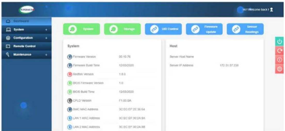
7.2 Intelligent Platform Management Interface (IPMI)
The system supports the Intelligent Platform Management Interface (IPMI). IPMI is used to provide remote access, monitoring, and management. There are several BIOS settings that are related to IPMI.
For general documentation and information on IPMI, please visit our website at: https://www.supermicro.com/solutions/IPMI.cfm.
text_image
SYSTEM Dashboard System Configuration Remote Control Maintenance System Firmware Version 00.10.76 Firmware Build Time 12/03/2020 Redfish Version 1.8.0 BIOS Firmware Version 1.0 BIOS Build Time 12/03/2020 CPLD Version F1.00.BA SMC MAC Address 3C:EC:EF:2E:36.64 LAN 1 MAC Address 3C:EC EF:30.2A.BA LAN 2 MAC Address 3C:EC EF:30.2A.BB Host Server Host Name Server IP Address 172.51.57.238Figure 7-2. IPMI Sample
7.3 Troubleshooting Procedures
Use the following procedures to troubleshoot your system. If you have followed all of the procedures below and still need assistance, refer to the Technical Support Procedures or Returning Merchandise for Service sections in this chapter. Power down the system before changing any non hot-swap hardware components.
General Technique
If you experience unstable operation or get no boot response, try:
- With power off, remove all but one DIMM and other added components, such as add-on cards, from the motherboard. Make sure the motherboard is not shorted to the chassis.
- Set all jumpers to their default positions.
- Power up. If the system boots, check for memory errors and add-on card problems.
No Power
- Check that the power LED on the motherboard is on.

text_image
A125C W-110 REV: 2.00 DESIGNED IN USA CPU LE3Figure 7-3. Location of the MB Power LED
• Make sure that the power connector is connected to the power supply.
- Check that the motherboard battery still supplies \~3VDC. If it does not, replace it.
- Check that the system input voltage is 100-120V or 180-240V.
- Turn the power switch on and off to test the system
No Video
If the power is on but you have no video, remove all add-on cards and cables.
System Boot Failure
If the system does not display Power-On-Self-Test (POST) or does not respond after the power is turned on, try the following:
- Turn on the system with only one DIMM module installed. If the system boots, check for bad DIMM modules or slots by following the Memory Errors Troubleshooting procedure below.
Memory Errors
- Make sure that the DIMM modules are properly and fully installed.
- Confirm that you are using the correct memory. Also, it is recommended that you use the same memory type and speed for all DIMMs in the system. See Section 3.3 for memory details.
- Check for bad DIMM modules or slots by swapping modules between slots and noting the results.
Losing the System Setup Configuration
- Use a high quality power supply. A poor quality power supply may cause the system to lose the CMOS setup information.
- Check that the motherboard battery still supplies \~3VDC. If it does not, replace it.
If the above steps do not fix the setup configuration problem, contact your vendor for repairs.
When the System Becomes Unstable
If the system becomes unstable during or after OS installation, check the following:
- CPU/BIOS support: Make sure that your CPU is supported and that you have the latest BIOS installed in your system.
- Memory: Make sure that the memory modules are supported. Refer to the product page on our website at www.supermicro.com. Test the modules using memtest86 or a similar utility.
-
Storage drives: Make sure that all drives work properly. Replace if necessary.
-
System cooling: Check that all heatsink fans and system fans work properly. Check the hardware monitoring settings in the BMC to make sure that the CPU and system temperatures are within the normal range. Also check the Control panel Overheat LED.
- Adequate power supply: Make sure that the power supply provides adequate power to the system. Make sure that all power connectors are connected. Refer to the Supermicro website for the minimum power requirements.
- Proper software support: Make sure that the correct drivers are used.
If the system becomes unstable before or during OS installation, check the following:
- Source of installation: Make sure that the devices used for installation are working properly, including boot devices.
- Cable connection: Check to make sure that all cables are connected and working properly.
- Use the minimum configuration for troubleshooting: Remove all unnecessary components (starting with add-on cards first), and use the minimum configuration (but with a CPU and a memory module installed) to identify the trouble areas.
-
Identify a bad component by isolating it. Check and change one component at a time.
-
Remove a component in question from the chassis, and test it in isolation. Replace it if necessary.
- Or swap in a new component for the suspect one.
- Or install the possibly defective component into a known good system. If the new system works, the component is likely not the cause or the problem.
7.4 Crash Dump Using IPMI
In the event of a processor internal error (IERR) that crashes your system, you may want to provide information to support staff. You can download a crash dump of status information using IPMI. The IPMI manual is available at https://www.supermicro.com/solutions/IPMI.cfm.
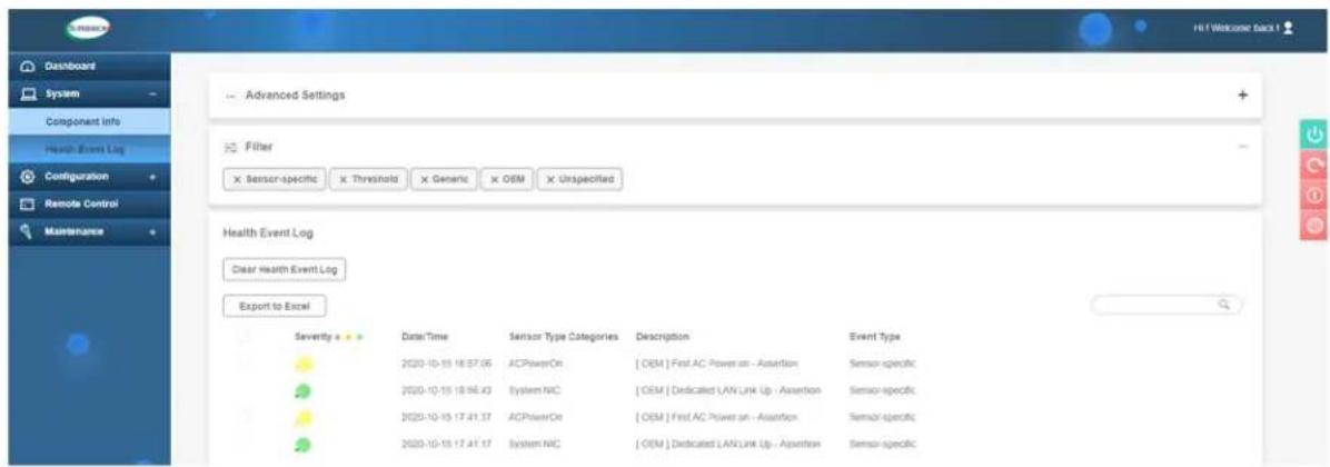
Check IPMI Error Log
- Access the IPMI web interface.
- Click the Server Health tab, then Event Log to verify an IERR error.
text_image
Health Event Log Clear Health Event Log Export to Excel Severity Date/Time Sensor Type Categories Description Event Type 2020-10-10 18:37:56 ACPowerOn [ OEM ] First AC Power on - Assertion Sensor-specific 2020-10-10 19:56:43 System AIC [ OEM ] Dedicated LAN Link Up - Assertion Sensor-specific 2020-10-10 17:41:37 ACPowerOn [ OEM ] First AC Power on - Assertion Sensor-specific 2020-10-10 17:41:37 System AIC [ OEM ] Dedicated LAN Link Up - Assertion Sensor-specificFigure 7-4. IPMI Event Log
In the event of an IERR, the IPMI executes a crash dump. You must download the crash dump and save it.
7.5 Where to Get Replacement Components
If you need replacement parts for your system, to ensure the highest level of professional service and technical support, purchase exclusively from our Supermicro Authorized Distributors/System Integrators/Resellers. A list can be found at: http://www.supermicro.com. Click the "Where to Buy" tab.
7.6 Reporting an Issue
Technical Support Procedures
Before contacting Technical Support, please take the following steps. If your system was purchased through a distributor or reseller, please contact them for troubleshooting services. They have the best knowledge of your specific system configuration.
- Please review the Troubleshooting Procedures in this manual and Frequently Asked Questions on our website before contacting Technical Support.
- BIOS upgrades can be downloaded from our website. Note: Not all BIOS can be flashed depending on the modifications to the boot block code.
-
If you still cannot resolve the problem, include the following information when contacting us for technical support:
-
System, motherboard, and chassis model numbers and PCB revision number
- BIOS release date/version (this can be seen on the initial display when your system first boots up)
- System configuration
An example of a Technical Support form is posted on our website. Distributors: For immediate assistance, please have your account number ready when contacting our technical support department by email.
Returning Merchandise for Service
A receipt or copy of your invoice marked with the date of purchase is required before any warranty service will be rendered. You can obtain service by calling your vendor for a Returned Merchandise Authorization (RMA) number. When returning to the manufacturer, the RMA number should be prominently displayed on the outside of the shipping carton, and mailed prepaid or hand-carried. Shipping and handling charges will be applied for all orders that must be mailed when service is complete.
For faster service, RMA authorizations may be requested online (http://www.supermicro.com/support/rma/).
Whenever possible, repack the chassis in the original Supermicro carton, using the original packaging material. If these are no longer available, be sure to pack the chassis securely, using packaging material to surround the chassis so that it does not shift within the carton and become damaged during shipping.
This warranty only covers normal consumer use and does not cover damages incurred in shipping or from failure due to the alteration, misuse, abuse, or improper maintenance of products.
During the warranty period, contact your distributor first for any product problems.
Vendor Support Filing System
For issues related to Intel, use the Intel IPS filing system:
https://www.intel.com/content/www/us/en/design/support/ips/training/welcome.html
For issues related to Red Hat Enterprise Linux, since it is a subscription-based OS, contact your account representative.
7.7 Feedback
Supermicro values your feedback as we strive to improve our customer experience in all facets of our business. Please email us at techwriterteam@supermicro.com to provide feedback on our manuals.
7.8 Contacting Supermicro
Headquarters
Address: Super Micro Computer, Inc.
980 Rock Ave.
San Jose, CA 95131 U.S.A.
Tel: +1 (408) 503-8000
Fax: +1 (408) 503-8008
Email: marketing@supermicro.com (General Information)
support@supermicro.com (Technical Support)
Website: www.supermicro.com
Europe
Address: Super Micro Computer B.V.
's-Hertogenbosch, The Netherlands
Tel: +31 (0) 73-6400390
Fax: +31 (0) 73-6416525
Email: sales@supermicro.nl (General Information)
support@supermicro.nl (Technical Support)
rma@supermicro.nl (Customer Support)
Website: www.supermicro.nl
Asia-Pacific
Address: Super Micro Computer, Inc.
3F, No. 150, Jian 1st Rd.
Zhonghe Dist., New Taipei City 235
Taiwan (R.O.C)
Tel: +886-(2) 8226-3990
Fax: +886-(2) 8226-3992
Email: support@supermicro.com.tw
Website: www.supermicro.com.tw
Appendix A
Standardized Warning Statements for AC Systems
About Standardized Warning Statements
The following statements are industry standard warnings, provided to warn the user of situations which have the potential for bodily injury. Should you have questions or experience difficulty, contact Supermicro's Technical Support department for assistance. Only certified technicians should attempt to install or configure components.
Read this appendix in its entirety before installing or configuring components in the Supermicro chassis.
These warnings may also be found on our website at http://www.supermicro.com/about/policies/safety_information.cfm.
Warning Definition

Warning! This warning symbol means danger. You are in a situation that could cause bodily injury. Before you work on any equipment, be aware of the hazards involved with electrical circuitry and be familiar with standard practices for preventing accidents.
警告の定義
この警告サインは危険を意味します。
Installation Instructions

Warning! Read the installation instructions before connecting the system to the power source.
設置手順書
Warning! This product relies on the building's installation for short-circuit (overcurrent) protection. Ensure that the protective device is rated not greater than: 250 V, 20 A.
サーキット・ブレーカー
Power Disconnection Warning
Warning! The system must be disconnected from all sources of power and the power cord removed from the power supply module(s) before accessing the chassis interior to install or remove system components.

text_image
CAUTION: This unit has redundant power sources. Please disconnect all the power cords before servicing.電源切断の警告
Equipment Installation

Warning! Only trained and qualified personnel should be allowed to install, replace, or service this equipment.
機器の設置
Warning! This unit is intended for installation in restricted access areas. A restricted access area can be accessed only through the use of a special tool, lock and key, or other means of security. (This warning does not apply to workstations).
アクセス制限区域
Warning! There is the danger of explosion if the battery is replaced incorrectly. Replace the battery only with the same or equivalent type recommended by the manufacturer. Dispose of used batteries according to the manufacturer's instructions
電池の取り扱い
Redundant Power Supplies

Warning! This unit might have more than one power supply connection. All connections must be removed to de-energize the unit.
冗長電源装置
Warning! Hazardous voltage or energy is present on the backplane when the system is operating. Use caution when servicing.
バックプレーンの電圧
Comply with Local and National Electrical Codes
Warning! Installation of the equipment must comply with local and national electrical codes.
地方および国の電気規格に準拠
Warning! Ultimate disposal of this product should be handled according to all national laws and regulations.
製品の廃棄
Warning! Hazardous moving parts. Keep away from moving fan blades. The fans might still be turning when you remove the fan assembly from the chassis. Keep fingers, screwdrivers, and other objects away from the openings in the fan assembly's housing.
ファン・ホットスワップの警告
Power Cable and AC Adapter
Warning! When installing the product, use the provided or designated connection cables, power cables and AC adaptors. Using any other cables and adaptors could cause a malfunction or a fire. Electrical Appliance and Material Safety Law prohibits the use of UL or CSA-certified cables (that have UL/CSA shown on the cord) for any other electrical devices than products designated by Supermicro only.
電源コードとACアダプター
System Specifications
Processors
3rd Generation Intel Xeon Scalable series [Socket P+ (LGA4189)] processor with up to 32 cores and a thermal design power (TDP) of up to 205W Note: Refer to the motherboard specifications pages on our website for updates to supported processors.
Chipset
Intel C621A
BIOS
256Mb AMI BIOS® SPI Flash BIOS
Memory
Eight slots support up to 2048GB of ECC RDIMM/LRDIMM/LRDIMM (3DS) with speeds up to 3200MHz; DIMM size up to 256GB at 1.2V
Storage Drives
Four fixed internal SATA3 2.5" drive bays
PCI Expansion Slots
Three PCIe 4.0 x16 slots One M.2 PCIe 3.0 x4/SATA3 Slot (supports M-Key 2280 and 22110)
Input/Output
Network: Two 10GbE LAN ports
IPMI: Dedicated LAN port
USB: Four USB 3.0 ports, two USB 2.0 ports
Video : One VGA port
Serial: One serial port
Motherboard
X12SPW-TF-001; 8" (W) x 13" (L) (203.2mm x 330.2mm)
Chassis
CSE-E403iF-000NBP Box Wall Mount, (WxHxD) 10.5 x 4.3 x 16in (267 x 109 x 406mm)
System Cooling
Three 8 x 3.8-cm heavy duty fans, one CPU heatsink, and one air shroud to direct airflow
Power Supply
Model: PWS-601-1H
AC Input Voltages: 100-240VAC
Rated Input Current: 3.5A-7.5A
Rated Input Frequency: 50-60Hz
Rated Output Power: 600W Single
Rated Output Voltages: +3.3V (16A), +5V (20A), +12V (49A (100-140VAC), 56A (180-240VAC)), +5VSB (3A)
Operating Environment
Operating Temperature: 0° to 45° C (32° to 113° F) Non-operating Temperature: -40° to 70° C (-40° to 158° F) Operating Relative Humidity: 8% to 90% (non-condensing) Non-operating Relative Humidity: 5% to 95% (non-condensing)
Certified Safety Models
Compliant with UL or CSA: E403iF-S6X12 and E403iF-6.
Regulatory Compliance
FCC, ICES, CE, UKCA, VCCI, RCM, NRTL, CB
Applied Directives, Standards
EMC/EMI: 2014/30/EU (EMC Directive)
Electromagnetic Compatibility Regulations 2016
FCC Part 15 Subpart B Class A
ICES-003
VCCI-CISPR 32
AS/NZS CISPR 32
EN/BS 55032
EN/BS 55035
CISPR 32
CISPR 24/CISPR 35
EN/BS 61000-3-2
EN/BS 61000-3-3
EN/BS 61000-4-2
EN/BS 61000-4-3
EN/BS 61000-4-4
EN/BS 61000-4-5
EN/BS 61000-4-6
EN/BS 61000-4-8
EN/BS 61000-4-11
Product Safety: 2014/35/EU (LVD Directive)
UL/CSA 62368-1 (USA and Canada)
Electrical Equipment (Safety) Regulations 2016
IEC/EN/BS 62368-1
Environment: 2011/65/EU (RoHS Directive)
EC 1907/2006 (REACH)
2012/19/EU (WEEE Directive)
California Proposition 65
Perchlorate Warning
California Best Management Practices Regulations for Perchlorate Materials: This Perchlorate warning applies only to products containing CR (Manganese Dioxide) Lithium coin cells. "Perchlorate Material-special handling may apply. See www.dtsc.ca.gov/hazardouswaste/perchlorate.