Arkan - Audio module Malstrom - Free user manual and instructions
Find the device manual for free Arkan Malstrom in PDF.

User questions about Arkan Malstrom
0 question about this device. Answer the ones you know or ask your own.
Ask a new question about this device
Download the instructions for your Audio module in PDF format for free! Find your manual Arkan - Malstrom and take your electronic device back in hand. On this page are published all the documents necessary for the use of your device. Arkan by Malstrom.
USER MANUAL Arkan Malstrom
text_image
ARKAN IN A CV BIA OUT IN CV B MALSTROMARKAN
USER MANUAL
CONTENTS
Description p. 3
Specs p. 4
Box Contents p. 4
Installation p. 4
Overview p. 5
Detailed view p. 6
Circuit Diagram p. 10
Patch Examples p. 11
Calibration & Settings p. 17
Warranty & Support p. 19
Special Thanks p. 19
DESCRIPTION
You must have seen this before: "You can never have enough VCAs". A voltage polarizer (also known as a bipolar VCA or a 4-quadrant multiplier) is often viewed as the VCA better suited for CV. As it can be used as a unipolar VCA and it allows you to invert a signal when it is modulated with a negative voltage. Resulting in interesting movements in your modulations.
What sets Arkan apart from other voltage polarizers is the curvature control, a feature usually only seen in unipolar VCAs. By taking a different approach to the classic voltage polarizer circuitry, we divised a unique solution that provides a new way to shape your audio and CV. The non-linearity of the polarizer also makes Arkan really good at reaching silence when presented with a 0V CV signal.
At audio rate, Arkan acts as a ring-modulator with four controls to change timbres. Boosting adds odd harmonics (symmetrical distortion), while offsetting adds even harmonics (asymmetrical distortion). The modulation curve changes ring modulation sharpness, and modulation strength determines the carrier dominance.
Two identical channels with carefully selected features will make Arkan your go-to modulation control hub. We find Arkan especially useful for common utility duties such as mixing, scaling, inverting and offsetting. As well as CV modulation, feedback patching, and waveshaping. All this makes Arkan a very versatile tool that will certainly have a place in your patch!
FEATURES (per channel)
- Input attenuation with inverter switch gives you more precision and range, with voltage inversion and quick silencing.
- Bias input with attenuverter control to offset your input signal or mix/invert another signal.
- CV input with curvature control allows you to shape the polarizer and improve its 0V attenuation.
- CV modulation control to fade in the modulator, allowing you to determine the amount of modulation.
- Voltage gain and polarity led indicators showing you exactly what is happening under the radar.
- Output normalled internally and externally (to other Arkans) to easily mix signals.
ADDITIONAL FEATURES
- Optional signal boost (x4 / +12dB) via switch on the pcb to increase voltages when needed.
- 5V or 10V voltage reference selection for bias voltage and CV input range to adjust Arkan to your system.
SPECS
FORMAT
EURORACK
WIDTH
8HP
FRONT
15MM
BACK
28MM
WEIGHT
125GR
POWER @ +12V
90mA
POWER @ -12V
85mA
BOX CONTENT
1x Module
1x Ribbon power cable
1x Link cable
2x Screws
2x Washers
2x Stickers
Note: All of our packaging is made from recycled materials and is 100% recyclable. We also choose to provide digital manuals only!
INSTALLATION
!!! WARNING !!! Be smart, turn power off before you start!
- Check there is enough power available on the power supply.
- Connect the 2x5 connector of the provided ribbon cable to the module.
- Check if the red stripe on the ribbon cable is connected to the red stripe indicator on the module. The red stripe indicator is the -12V rail.
- Connect the 2x8 connector of provided ribbon cable to the busboard.
- Check if the red stripe on the ribbon cable is connected to the -12V position on the busboard.
- Fasten the provided screws to lock the module onto the eurorack system rails.
- Turn power on and enjoy!
Note: Malstrom modules have reverse polarity protection. Reversed power connection will not damage the module.
OVERVIEW

flowchart
graph TD
    A["1"] --> B["2"]
    B --> C["3"]
    C --> D["10"]
    D --> E["11"]
    E --> F["12"]
    F --> G["13"]
    G --> H["16"]
    H --> I["OUT"]
    style A fill:#f9f,stroke:#333
    style B fill:#f9f,stroke:#333
    style C fill:#f9f,stroke:#333
    style D fill:#f9f,stroke:#333
    style E fill:#f9f,stroke:#333
    style F fill:#f9f,stroke:#333
    style G fill:#f9f,stroke:#333
    style H fill:#f9f,stroke:#333
    style I fill:#f9f,stroke:#333
    subgraph Section A
        A1["IN"] --> A2["6"]
        A2 --> A3["5"]
        A3 --> A4["7"]
        A4 --> A5["9"]
        A5 --> A6["4"]
        A6 --> A7["15"]
        A7 --> A8["14"]
        A8 --> A9["16"]
        A9 --> A10["18"]
        A10 --> A11["12"]
        A11 --> A12["13"]
        A12 --> A13["17"]
        A2 -->|BIAIS| B
        A3 -->|BIAIS| B
        A4 -->|BIAIS| B
        A5 -->|BIAIS| B
        A6 -->|OUT| B
        A7 -->|OUT| B
        A8 -->|OUT| B
        A9 -->|OUT| B
        A10 -->|OUT| B
        A11 -->|OUT| B
        A12 -->|OUT| B
        A13 -->|OUT| B
        A14 -->|OUT| B
        A15 -->|OUT| B
        A16 -->|OUT| B
        A17 -->|OUT| B
        A18 -->|OUT| B
        A19 -->|OUT| B
        A20 -->|OUT| B
    end
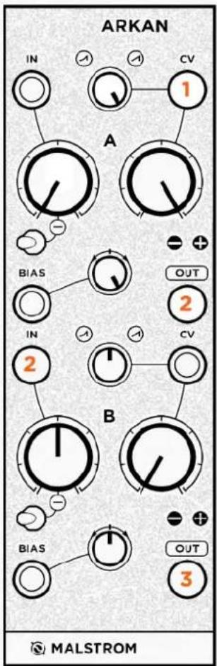
- Channel A Input
- Channel A Gain Knob
- Channel A Bias Input
- Channel A Bias Attenuverter
- Channel A Modulation (CV) Input
- Channel A Modulation Curve
- Channel A Modulation Strength
- Channel A Output
-
Channel A Inverter Switch
-
Channel B Input
- Channel B Gain Knob
- Channel B Bias Input
- Channel B Bias Attenuverter
- Channel B Modulation (CV) Input
- Channel B Modulation Curve
- Channel B Modulation Strength
- Channel B Output
- Channel B Inverter Switch
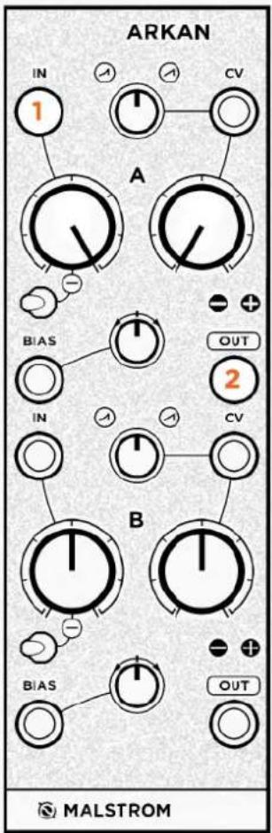
DETAILED VIEW
text_image
IN CV A BIA OUTArkan is vertically divided into two identical channels like the layout on the left.
This layout can be divided into four sections. The input, bias, modulation and output sections.
INPUT
The input section consists of an input, linear gain knob and inverter switch.
This section does nothing when there is no source in the input. Once you patch the input you can adjust the gain with the knob. The knob reaches unity gain at the second line (see note).
The inverter switch inverts the incoming input signal when it is set to the right position (the switch is facing the inverting symbol). Otherwise it does not invert.
text_image
INNote: this knob is set to gain x4 (+12dB). Particularly useful for distortion, or line to modular level conversion. Alternatively it can only attenuate see page 18 to learn how to set it.
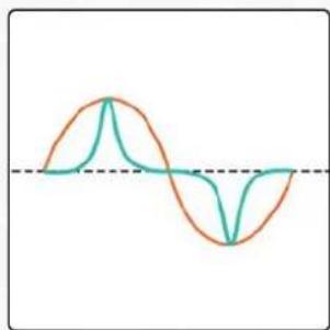
If the input gain knob is set to amplify x4 (as stated on the previous page), the input signal will start to distort once it passes \~10V. This distortion is symmetrical hard clipping and adds uneven harmonics.
The graph on the right shows the result (cyan) of hard clipping on a sine wave (orange).

natural_image
Pure wave-like diagram with two overlapping curves and a horizontal dashed line (no text or symbols)BIAS
The bias section consists of an input and an attenuverter trimmer.
This section works slightly different to the input section. As it generates a voltage when it does not have anything patched in the input.
This voltage can be used to offset the signal of the input section, or to simply generate a voltage. The voltage corresponds to the knob position and can be negative or positive (see note). Offsetting a signal will cause it to shift up or down in voltage.
When the offset causes the input section signal to pass \~10V it will start to distort. This distortion is asymmetrical hard clipping and adds even harmonics. The graph on the right shows the result (cyan) of asymmetrical clipping on a sine wave (orange).
flowchart
graph TD
    A[" "] --> B[" "]
    style A fill:#fff,stroke:#000
    style B fill:#fff,stroke:#000

line
| x | Line 1 | Line 2 | | ---- | ------ | ------ | | 0 | 0.5 | 0.5 | | 1 | 0.7 | 0.6 | | 2 | 0.8 | 0.7 | | 3 | 0.6 | 0.8 | | 4 | 0.4 | 0.9 | | 5 | 0.2 | 0.8 | | 6 | 0.1 | 0.7 | | 7 | 0.3 | 0.6 | | 8 | 0.5 | 0.5 | | 9 | 0.7 | 0.4 | | 10 | 0.9 | 0.3 | | 11 | 0.8 | 0.2 | | 12 | 0.6 | 0.1 | | 13 | 0.4 | 0.0 | | 14 | 0.2 | -0.1 | | 15 | 0.1 | -0.2 | | 16 | 0.3 | -0.3 | | 17 | 0.5 | -0.4 | | 18 | 0.7 | -0.5 | | 19 | 0.9 | -0.6 | | 20 | 1.1 | -0.7 | | 21 | 1.3 | -0.8 | | 22 | 1.5 | -0.9 | | 23 | 1.7 | -1.0 | | 24 | 1.9 | -1.1 | | 25 | 2.1 | -1.2 | | 26 | 2.3 | -1.3 | | 27 | 2.5 | -1.4 | | 28 | 2.7 | -1.5 | | 29 | 2.9 | -1.6 | | 30 | 3.1 | -1.7 | | 31 | 3.3 | -1.8 | | 32 | 3.5 | -1.9 | | 33 | 3.7 | -2.0 | | 34 | 3.9 | -2.1 | | 35 | 4.1 | -2.2 | | 36 | 4.3 | -2.3 | | 37 | 4.5 | -2.4 | | 38 | 4.7 | -2.5 | | 39 | 4.9 | -2.6 | | 40 | 5.1 | -2.7 | | 41 | 5.3 | -2.8 | | 42 | 5.5 | -2.9 | | 43 | 5.7 | -3.0 | | 44 | 5.9 | -3.1 | | 45 | 6.1 | -3.2 | | 46 | 6.3 | -3.3 | | 47 | 6.5 | -3.4 | | 48 | 6.7 | -3.5 | | 49 | 6.9 | -3.6 | | 50 | 7.1 | -3.7 | | 51 | 7.3 | -3.8 | | 52 | 7.5 | -3.9 | | 53 | 7.7 | -4.0 | | 54 | 7.9 | -4.1 | | 55 | 8.1 | -4.2 | | 56 | 8.3 | -4.3 | | 57 | 8.5 | -4.4 | | 58 | 8.7 | -4.5 | | 59 | 8.9 | -4.6 | | 60 | 9.1 | -4.7 | | 61 | 9.3 | -4.8 | | 62 | 9.5 | -4.9 | | 63 | 9.7 | -5.0 | | 64 | 9.9 | -5.1 | | 65 | 10.1 | -5.2 | | 66 | 10.3 | -5.3 | | 67 | 10.5 | -5.4 | | 68 | 10.7 | -5.5 | | 69 | 10.9 | -5.6 | | 70 | 11.1 | -5.7 | | 71 | 11.3 | -5.8 | | 72 | 11.5 | -5.9 | | 73 | 11.7 | -6.0 | | 74 | 11.9 | -6.1 | | 75 | 12.1 | -6.2 | | 76 | 12.3 | -6.3 | | 77 | 12.5 | -6.4 | | 78 | 12.7 | -6.5 | | 79 | 12.9 | -6.6 | | 80 | 13.1 | -6.7 | | 81 | 13.3 | -6.8 | | 82 | 13.5 | -6.9 | | 83 | 13.7 | -7.0 | | 84 | 13.9 | -7.1 | | 85 | 14.1 | -7.2 | | 86 | 14.3 | -7.3 | | 87 | 14.5 | -7.4 | | 88 | 14.7 | -7.5 | | 89 | 14.9 | -7.6 | | 90+ (long) | ~0 | ~-0 |Alternatively the offset voltage can be replaced with a signal by inserting a cable in the bias input. In which case the signal is mixed with the input section. The attenuverter determines the bias input signal polarity and gain.
Note: this offset can be set to +-5V or +-10V. See page 17 to learn how to set it.
MODULATION
The modulation section consists of an input, a curvature trimmer and a modulation strength knob. This section is used to modulate the mix of the input and bias section.
The CV input (see note) is a voltage polarizer, which means that it changes the amplitude as well as the polarization of the mix. I.e. applying a negative voltage in the CV input, will cause the mix to be inverted.

text_image
A A CVA polarizer is especially useful for waveshaping. As the CV input responds to bipolar signals, such as audio. Additionally it is useful to modulate your modulation sources, as inverting can result into interesting movements that are unavailable with unipolar VCAs.
The curvature trimmer determines the shape response of the polarizer, moving from exponential to linear. The graph on the right shows how the function works in polarizer form. The linear (orange) line is how polarizers normally function, while the exponential (cyan) is what is also achievable with Arkan.
line
| Voltage | Current | | ------- | ------- | | +5V | -5V | | 0V | 0V |The curvature can also be used to adjust the sharpness of a modulation source. When the bias section is generating a voltage. The modulator signal is transferred to the output, but now has curve control. The graph on the right shows the result (cyan) of a sine wave LFO (orange) transfer.
natural_image
Two overlapping waveforms (orange and teal) with a horizontal dashed line at the bottom, no text or symbols present.This means that you can shape your audio or adjust the tone when using it as a ring modulator. Or make your modulation sources swoop more, coming in slow but strong.
Finally this non-linear function of the polarizer allows it to go silent really well when 0V is applied. Simply set it to anything but fully linear!
Note: the CV Input can be set to respond to +-5V or +-10V, see page 17 to learn how to set it.
The modulation-strength knob fades in the modulator signal. Meaning that the signal remains unmodulated when the modulation-strength knob is fully CCW. The signal is being modulated at maximum potential when the modulation-strength knob is fully CW.
With ring modulation; the modulation-strength knob determines the carrier (input & bias section) dominance. The graph on the right shows the result (cyan) of two sines waves (orange) modulating, with a more dominant carrier signal. Note that when the modulator is negative the carrier starts to fold into itself, opposed to fully inverting.
When a modulation source is being modulated the modulation-strength knob gives control over how dynamic your modulations are. As you turn the knob the result starts to deviate more from the original modulation signal and the new modulation signal becomes more apparent.

line
| Time | Series 1 | Series 2 | Series 3 | |------|----------|----------|----------| | 0 | 0 | 0 | 0 | | 1 | 100 | 0 | 0 | | 2 | 0 | 100 | 0 | | 3 | -100 | 0 | 0 | | 4 | 0 | 100 | 0 | | 5 | 100 | 0 | 0 | | 6 | 0 | 100 | 0 | | 7 | -100 | 0 | 0 | | 8 | 0 | 100 | 0 | | 9 | 100 | 0 | 0 | | 10 | 0 | 100 | 0 | | 11 | -100 | 0 | 0 | | 12 | 0 | 100 | 0 | | 13 | 100 | 0 | 0 | | 14 | 0 | 100 | 0 | | 15 | -100 | 0 | 0 | | 16 | 0 | 100 | 0 | | 17 | 100 | 0 | 0 | | 18 | 0 | 100 | 0 | | 19 | -100 | 0 | 0 | | 20 | 0 | 100 | 0 | | 21 | 100 | 0 | 0 | | 22 | 0 | 100 | 0 | | 23 | -100 | 0 | 0 | | 24 | 0 | 100 | 0 | | 25 | 100 | 0 | 0 | | 26 | 0 | 100 | 0 | | 27 | -100 | 0 | 0 | | 28 | 0 | 100 | 0 | | 29 | 100 | 0 | 0 | | 30 | 0 | 100 | 0 | | 31 | -100 | 0 | 0 | | 32 | 0 | 100 | 0 | | 33 | 100 | 0 | 0 | | 34 | 0 | 100 | 0 | | 35 | -100 | 0 | 0 | | 36 | 0 | 100 | 0 | | 37 | 100 | 0 | 0 | | 38 | 0 | 100 | 0 | | 39 | -100 | 0 | 0 | | 40 | 0 | 100 | 0 | | 41 | 100 | 0 | 0 | | 42 | 0 | 100 | 0 | | 43 | -100 | 0 | 0 | | 44 | 0 | 100 | 0 | | 45 | 100 | 0 | 0 | | 46 | 0 | 100 | 0 | | 47 | -100 | 0 | 0 | | 48 | 0 | 100 | 0 | | 49 | 100 | 0 | 0 | | 50 | 0 | 100 | 0 | | ... (multiple values)Finally if there is no CV input present the modulation-strength knob functions as an attenuator for the input and bias mix but in reverse (CCW is fully gained, CW is silent).
OUTPUT
Each output is equipped with two leds showing amount of gain from 0V. Where the “-” lights up whenever the output signal is below 0V and the “+” lights up whenever the output signal is above 0V.
Additionally the outputs are normalled, meaning that if an output is left unpatched its signal is passed and mixed at the next output. This link can be broken by inserting a cable in the first output. (Note: the outputs can be linked to other Arkans see page 18 for more info).
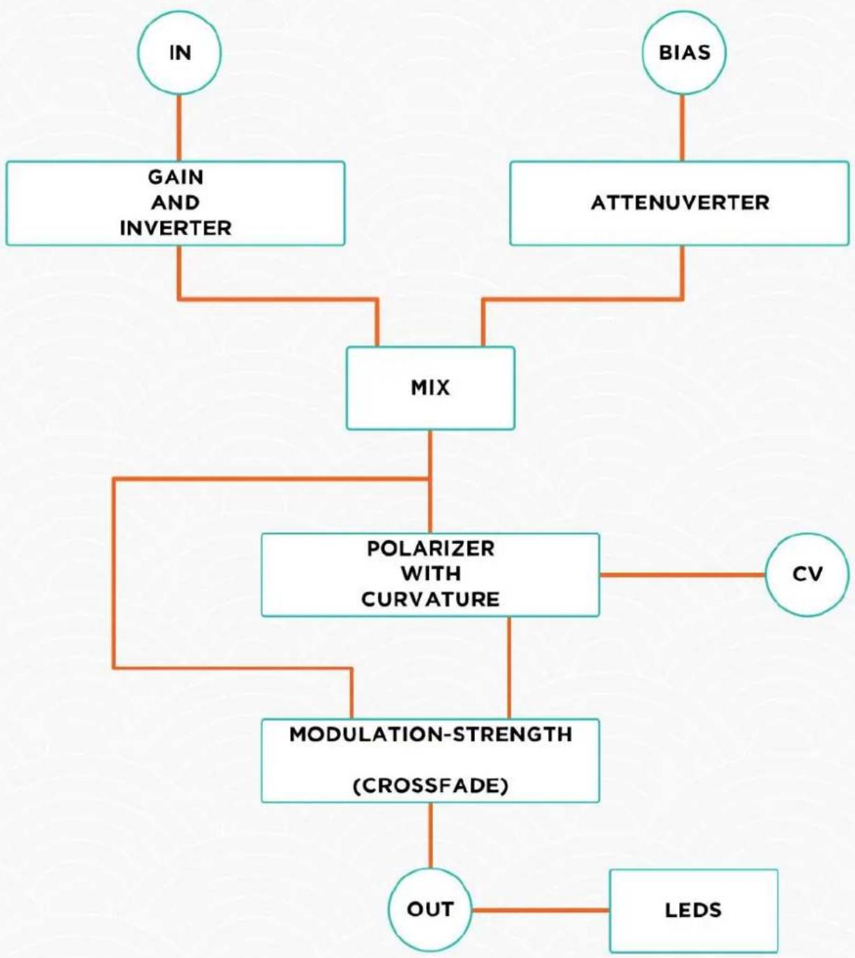
CIRCUIT DIAGRAM
The following diagram shows how one channel of Arkan is connected.
flowchart
graph TD
    IN["IN"] --> GAIN["GAIN AND INVERTER"]
    IN --> MIX["MIX"]
    BIAS["BIAS"] --> ATTENUVERTER["ATTENUVERTER"]
    MIX --> POLARIZER["POLARIZER WITH CURVATURE"]
    POLARIZER --> CV["CV"]
    POLARIZER --> MODULATION_STRENGTH(MODULATION-STRENGTH (CROSSFADE))]
    MODULATION_STRENGTH --> OUT["OUT"]
    OUT --> LED["LEDS"]
PATCH EXAMPLES
EXAMPLE 1: BASIC TOOL
This patch shows you how to use the very basic functions of a channel. The goal is to get a patch going as quickly as possible. To simplify we will only be using the first channel. And focus on setting gain, inverting and offsetting. Standard settings are used here (see page 18).
Start off by copying the knob positions as shown in the example below. And prepare a patch with an oscillator going into a filter. Make sure the CV attenuator on the filter is set fully CW.
PATCH
- Patch an LFO into Input 1.
- Patch Output 1 to a filter's cutoff CV input.
NOTES
The Input Gain Knob functions as a gain knob and will determine the LFO's strength. To get unity gain set it to the second line indicator. To invert the LFO's polarity, set the Inverter Switch to a different setting. The Bias Knob can be used to offset the LFO.
The Modulation-Strength Knob can be used to attenuate the input and bias section together. Just remember that maximum attenuation is at full CW position.
text_image
ARKAN IN 1 A CV BIA5 OUT 2 IN CV B BIA5 OUT MALSTROMEXAMPLE 2: BASIC AMPLITUDE MODULATOR
This patch dives into the modulation section and is meant to show how to get an amplitude modulation patch going. For this patch you will need two audio rate oscillators. Standard settings are used here (see page 18).
Start off by copying the knob positions as shown in the example below.
PATCH
- Patch an oscillator into Input 1.
- Patch an oscillator into CV Input 1.
- Patch Output 1 to anything.
NOTES
The Input Gain Knob controls the carrier gain.
The Modulation-Strength Knob controls the amount of modulation.
The Modulation Curve Trimmer controls the shape of the modulation.
Tip: Continue by unpatching Output 1 and inserting its cable into Output 2. Then patch more signals into all of the inputs.

text_image
ARKAN IN 1 CV 2 A B IN OUT 3 CV B MALSTROMEXAMPLE 3: WAVESHAPER AND DISTORTION
This patch is meant to show how you can utilize the two channels to create a waveshaper and distortion. It also shows two different building blocks that can be used. Standard settings are used here (see page 18).
Start off by copying the knob positions as shown in the example below.
PATCH
- Patch an oscillator into CV Input 1.
- Patch Output 1 to Input 2.
- Patch Output 2 to an audio mixer or filter (see note).
Note: Adding uneven harmonics adds offset to the sound. Patching to a filter or audio mixer will bring the signal back to \~0V!
NOTES
The first channel is used as a linear to exponential waveshaper. The bias section generates a voltage which is modulated. This results in a wave transfer where the Modulation Curve control adjusts the waveshape curve.
The second channel is used as a two type distortion. The Input Gain Knob is hard clipping and adds uneven harmonics. The Bias control is offset and adds uneven harmonics.
Tip: Continue by adding more sources to the different inputs. Combine mixing and amplitude modulation with waveshaping and distortion.
text_image
ARKAN IN CV 1 A BIA5 OUT 2 IN CV 2 B MALSTROM BIA5 OUT 3EXAMPLE 4: DYNAMIC MODULATION CONTROLLER
This patch dives into the modulation section and is meant to show how Arkan can be used to create dynamic modulations. Generally it works best with two modulation sources that have different time settings. With the carrier set up faster than the modulator. To create this patch you will need two LFOs. But we can recommend an envelope and LFO combination too. Standard settings are used here (see page 18).
Start off by copying the knob positions as shown in the example below. And prepare a patch with an oscillator going into a filter. Make sure the CV attenuator on the filter is set fully CW.
PATCH
- Patch an LFO into Input 1.
- Patch an envelope into CV Input 1.
- Patch Output 1 to a filters CV input.
NOTES
Now we can start make use of the several functions that Arkan gives us.
The Input Gain Knob determines the strength of the fast moving modulation.
The Bias controls the initial voltage as well as the range of the slow moving modulation.
The Modulation-Strength Knob controls how much the slow moving modulation will pass through.
The Curve Knob controls the shape of the slow moving modulation.
Tip: Continue with different knob settings, LFO time settings and modulation sources.

text_image
ARKAN IN CV A BIA OUT IN CV B MALSTROMEXAMPLE 5: OCTAVER AND TRIANGLE TO PARABOLIC WAVESHAPER
This patch works as a waveshaper and creates an octaver-like effect at audio rate. The idea is to modulate a signal with itself and make use of the modulation-strength knob to determine the shape and sound. It works best with a triangle wave but a sine wave can be used too. Additionally it can be used to convert a triangle wave to a parabolic wave. Standard settings are used for this patch (see page 18).
Start off by copying the knob positions as shown in the example below.
PATCH
- Patch a triangle wave at audio rate into Input 1.
- Patch the same triangle wave into CV Input 1, with a stackable or mult.
- Patch Output 1 to an audio mixer or filter (see note).
NOTES
As you increase the Modulation-Strength Knob the triangle wave will start to fold into itself. Creating a parabolic wave with the Modulation-Strength Knob at around 11:00. An inverted parabolic wave can be made by simply using the Inverter Switch.
With the Modulation-Strength Knob fully CW the folding effect results in a new wave that is double the speed of the original triangle wave, Thus creating a sound that is one octave higher. The Modulation-Strength Knob acts as a fader between the low and high octave waves.
Note: with this patch DC offset is added to the signal. Which is why in step 3 of the patch we follow up with an audio mixer or filter. Alternatively we can skip the first output and step 3. And use the second output instead. We can then use the DC offset at the second channel to compensate.

text_image
ARKAN IN 1 CV 2 A B IN OUT 3 CV B MALSTROMEXAMPLE 6: MELODY CONTROLLER
This patch works as a melody controller which combines stepped, random and smooth (LFOs) voltages to generate melodies. It is important to forget about the v/oct scale with the Arkan controls, as v/oct will not work in this case. Instead we will be using a quantizer to convert these voltages to v/oct. To create this patch you will need a quantizer that allows you to set scales. You will also need a sequencer, a stepped random source and an LFO source. Standard settings are used for this patch (see page 18).
Start off by copying the knob positions as shown in the example below. And prepare a patch with a quantizer going into an oscillator's v/oct.
PATCH
- Patch a stepped random source into Input 1.
- Patch a sequencer output into Bias Input 1.
- Patch an Ifo into CV Input 1.
- Patch Output 1 to a quantizer's v/oct input.
NOTES
The bias section controls the direction and range of your sequencer melody. Remember that v/oct is not transferred directly. So your sequencer's output are only reference voltages.
The input section controls how strong the randomness will occur within the melody. Leaving the Input Gain knob CCW will result in no randomness. Increasing randomness as you turn it CW.

text_image
ARKAN IN 1 CV 3 A BIA5 2 OUT 4 IN CV B BIA5 OUT MALSTROMThe modulation section adds sweeps and shifts to the melody. It also inverts your melody when it is fully CW.
Tip: Use a mult or stackable to send the output to a filters CV input. And make the cutoff follow the melody, increasing as the melody goes higher!
Note: this patch is a simplified version of one that was made by Maarten Vos. You can find a video of his patch on malstromaudio.com/arkan.
CALIBRATION & SETTINGS
CALIBRATION
You can calibrate the modulated and unmodulated signal to be the same level. I.e. if there is a +5V or +10V modulation source and the modulation-strength knob is to the right, the signal has the same gain as when the modulation-strength knob is to the left.
Arkan comes calibrated, only do this when you change settings or consider it necessary!
The calibration can be done by ear, or multi-meter when more accuracy is wanted.
Start off by copying the knob positions as shown in the example right. The example is for calibration by ear. To do calibration with a multi-meter: skip step 2.
- Patch Output 1 to CV Input 2.
- Insert an oscillator to Bias Input 2.
- Patch Output 2 to listen or measure.

text_image
ARKAN IN CV A BIA OUT 1 IN CV 1 B BIA 2 OUT 3 MALSTROMWe will now compare the output when the
Modulation-Strength Knob of channel B is fully CCW and fully CW. The goal is to get them more or less the same, by adjusting the pcb trimmer labeled as "VCA ADJUST". Go back and forth with the Modulation-Strength Knob, adjusting until you are satisfied.
CV AND BIAS VOLTAGE RANGE SETTING
Arkans CV and bias voltage range can be set to your needs. Meaning that the full CV gain can be either +-5V or +-10V. The bias voltage generated also uses this setting as its range. So remember that this is one setting.
Change this setting by switching to the preferred setting on the pcb switch labeled as "V-REF". Once you change this you will need to proceed and follow the calibration instructions above!
BOOST SETTING
The Input Gain Knobs can boost x1 or x4 (+12dB). This setting applies to both Input Gain Knobs of the two channels. We recommend x4 when using Arkan mostly as distortion or waveshaper. Change this setting by switching to the preferred setting on the pcb switch labeled as "BOOST".
DAISY CHAINING
When you have more Arkans, their outputs can be chained and mixed. Use the provided link cable to connect the pcb pin labeled as "OUT" of one module to the pcb pin labeled as "IN" of the other module. This connection can be broken by inserting a cable in the output of channel B of the Arkan that uses the "OUT" connection.
STANDARD SETTINGS
Standard factory settings are:
- "V-REF": +-5V.
- "BOOST": x4.
I/O SPECS
- All inputs are DC coupled.
- All inputs handle audio signals.
- All inputs have 100k input impedance.
- CV inputs expect +-5V or +-10V voltage range.
- All other inputs have +-10V input range.
- All inputs are over voltage protected.
- Bias voltage +-5V or +-10V voltage range.
- Output +-10V voltage range.
- Keyed power header and reverse power protection.
WARRANTY & SUPPORT
WARRANTY
We guarantee that all of our products are tested before shipping. However it may be that you are experiencing problems with a product. Do not worry we are here to help! Within one year after purchase, any damaged or malfunctioning products will be repaired, serviced and calibrated on a return-to-factory basis. However this service is only guaranteed if the damages are not caused during shipping, installation, incorrect usage or user inflicted damages.
Even after the one year warranty, or if the damages are caused by the before mentioned causes; we want to help you. Products will still be repaired but we reserve the right to charge you for labor, parts and transit expenses.
In any case we advise you to contact us about any issues!
SUPPORT
For any support head over to our support page: malstromaudio.com/support.
Or send us a mail at info@malstromaudio.com and we will get back to you as soon as possible.
SPECIAL THANKS
We would like to thank these people for feedback and testing:
Ben "Divkid" Wilson, Henning Schonvogel, Jason Brunton, Maarten Vos, Max Frimout, Morten "Momec" Berthelsen and Sjam Sjamsoedin.
And also:
Manu Retamero and Steve Grimley-Taylor.