Cascading Register - Synthesizer Omiindustriies - Free user manual and instructions
Find the device manual for free Cascading Register Omiindustriies in PDF.

User questions about Cascading Register Omiindustriies
0 question about this device. Answer the ones you know or ask your own.
Ask a new question about this device
Download the instructions for your Synthesizer in PDF format for free! Find your manual Cascading Register - Omiindustriies and take your electronic device back in hand. On this page are published all the documents necessary for the use of your device. Cascading Register by Omiindustriies.
USER MANUAL Cascading Register Omiindustriies
text_image
Cascading Register Clock CV Clock Out Clock in Clock Rate Data CV 1 + CV 2 + CV 3 + omiindustriies Seed ØØ Ø1 Ø2 Ø3 Ø4 Ø5 Ø6 Ø7The Cascading Register from omiiindustriiesisasourceofpseudo-randomvoltagesandgates usinganeight-bitshiftregister. It takes inspiration from digital shift registers, runglers, linear feedback shift registers (LFSR), and analog shift registers.
Quickstartguide
PlugtheCascadingRegisterintoyourEurorackpowersupply,makingsurethepowerisoffand theredstripeindicating-12Visfacingdown.Turnonthe powersupply.

natural_image
Close-up of a green printed circuit board with electronic components and traces (no readable text or symbols)Whenyoufirstpoweronthemodule,alloftheblueLEDs willbeonoroff.PressingtheSeedbuttonatthebottomof themoduleorpatchingagatesignalintotheDatainputwill addnewdataintotheregister,andyoushouldseethelights begintomovefromtoptobottom.Don'tbesurprisedifthe rateisn'tsteady,astethirdCVoutputmodulatesthe
frequencyoftheinternalclockoscillator.Nowyou'refreetopatchtheCascadingRegisterto otherpartsofyourEuroracksystem.
Try inputting different gate signals into the Data input or clock it from an external clock source such as aclockdivider. UseethreesteppedCVoutputstomodulateparameters such as pitchortimbreonanoscillatorandusethegatesignalstoprovidetimingsignalstoinitializean envelopeorplayasample.Nowthatyouhavethatgoing, let'stakealookunderthehood and explorethemodulemorein-depth

text_image
Cascading Register Clocking Clock CV Clock Out Clock in Clock Rate Data CV 1 + - CV 2 + - CV 3 + - omiindustries Seed Data Gate outputs 07 06 05 04 03 02 01 00The Cascading Registerist the continuation of ideas put forward with the first omi industries module, the Dual Digital Shift Register (DDSR). This module looked to Rob Hordijk's famous (or infamous) circuit at the heart of the Benjolin and Blippoo Box, the Rungler. But before wedive into the specific implementation of historic shift registers, we must look at how they actually work.
Shiftregistersindetail
DigitalShiftRegisters
A shift register has a clock input and a data input. In the case of digital shift registers, the data input is a binary input with only two states, on or off. On the rising edge of a timing/clock signal (typically a gate or trigger signal) greater than 0.5V at the clock input, the shift register looks at thedatainput.Ittakesthestateofthesignalpresentatthedatainputandputsitintothefirst stageoftheregister,(∅∅).Inthiscase,it'saneight-bitshiftregister,meaningithaseight stages,zero-indexedfrom∅∅to∅7.Ifthesignalpresentatthedatainputisabove0.5V,it movesahighsignalintothefirststage(∅∅),andifit'slow,itmovesalowstateintothefirst stage.Additionally,oneveryclockpulse,whateverdataisinthefirststagemovestothesecond (∅1),whateverisinthesecondstagemovestothethird(∅2),andsoonandsoforth.Whena bitofinformationreachesthfinalstage,∅7,thedataisshiftedoutoftheregister.
TheexternaldatainputisnottheonlysourceofdatawithintheCascadingRegister.The illuminatedSeedbuttononthebottomofthemoduleallowsyoutomanuallyseednewdatainto theregister.Additionally,threeofthestagesarefeedbackintothedatastreamalongwiththe externaldataandthebutton.
LinearFeedbackShiftRegister(LFSR)
ThisbringsustooursecondformofinspirationfortheCascadingRegister,thelinearfeedback shiftregister(LFSR).AnLFSRisacommonwaytogeneratepseudo-randomnumberswithin bothhardwareandsoftware.Duetothefactthatyoucannotreplicatethermalnoisepresentin analognoisegenerators,programmersmustgeneraterandomnesswithincode.Inlieuofan externaldatasource,anLFSRusesthedataintheregisterandfeedsthatbackintoitselfto generatethepseudo-randompattern.TheLFSRtakestwoormoreofthestagespresentinthe shiftregisterandcombinesthemthroughaBooleanlogicfunction,typicallyXOR.XORis
| A | B | XOR |
| — | — | — |
| — | ||
| — | ||
| — |
typicallyatwo-inputlogicgate,wheretheoutputisactiveifoneofthe inputsortheotherisactive,butinactiveifbothorneitherare.Put anotherway,theoutputisactiveifthetwoinputsdon'tmatch,and inactiveifthetwoinputsdomatch.
Theselectionofstageswithinashiftregisterdeterminesthelengthofthe pseudo-randompattern.Inaneight-bitshiftregister,takingthefourth, fifth,sixth,andeighthstagesoftheshiftregisterandXOR'ingthem togethergeneratesthelongeststreamofpseudo-randomnumbers,255
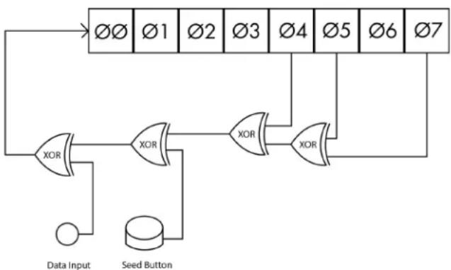
stageslong. This is called the maximal length shift register, whose length is 2^n-1, so to the eighth power, minus one. What happens if all the bits are 0? No data are recycled back into the register, so this is an invalid state. This is there as that the maximal length of the pattern is 2^n-1: there are 2^n possible combinations of bits, but were removed that will not work with the LFSR. The Cascading Register is not a maximal length shift register, as it takes only the 5th (04), 6th (05), and 8th (07) stages and XOR sthem with both the external data input and theseed button located on the bottom of the module. In order, 07 is XOR 'd with 05, that output is XOR 'd with 04, that is XOR 'd with theseed button, and that is XOR 'd with the external data input.
flowchart
graph TD
    A["∅Ø"] --> B["XOR"]
    C["∅1"] --> D["XOR"]
    E["∅2"] --> F["XOR"]
    G["∅3"] --> H["XOR"]
    I["∅4"] --> J["XOR"]
    K["∅5"] --> L["XOR"]
    M["∅6"] --> N["XOR"]
    O["∅7"] --> P["XOR"]
    Q["Data Input"] --> R["XOR"]
    S["Seed Button"] --> T["XOR"]
    U["∅"] --> V["XOR"]
    W["∅"] --> X["XOR"]
Tocreatethemaximallengthshiftregister configurationwiththeCascadingRegister, simplypatchtheoutputofthethirdstage ∅2, intotheexternaldatainput.
In addition to the eight gate outputs located on the right side of the Cascading Register, it includes three CV outputs. The state of the eight stages of the shift register determines the level of the CV outputs. The
moduleusesthreesimpledigitaltoanalogconverters(DACs)inordertogeneratesteppedCVs fromthegates.CV1isderivedfrombits∅∅,∅1,∅2,∅3,CV2comesfrombits∅2,∅3,∅4,∅5, andCV3usesbits∅4,∅5,∅6,∅7. Noticehowthefirststageofeachofthethreesetsis shiftedbytwostages. ThefourbitsofdatapresentinCV1passintoCV2aftertwoclockpulses, andthentoCV3afteranothertwoclockpulses. Thiscreatesaneffectreminiscentofananalog shiftregister.
AnalogShiftRegister(ASR)
Ananalogshiftregisterisessentiallyaseriesofsampleandholds.Insteadofbinarydatainput, thedataorsamplinginputonasampleandholdacceptscontinuousvoltages.Whenthesample andholdreceivesatimingsignalattheclockinput,ittakesasnapshotofthevoltagelevel presentatthesamplinginputandmovesittotheoutput.Whenitreceivesanothertimingsignal, thesampleandholdlooksagainatthesamplinginputandmovesthatvoltagelevelintothe output.Withananalogshiftregister,thevoltagelevelpassesfromonesampleandholdtothe nextoneinthelinearchainofvoltageinformation.Soeverytimetheanalogshiftregistergetsa timingsignal,thefirstsampleandholdsamplesanewvalueandtheoldvaluepassestothe secondsampleandholdintheline,almostlikeagameoftelephone.Whenusedtosequence thepitchofmultipleoscillators,itcreatesacanonicmusicalstructureknownasanarabesque. WhiletheCascadingRegisterusesadigitalshiftregisterinsteadofaseriesofsampleand holds,thesteppedpseudo-randomsequencepasseslinearlyfromthefirstCVoutputtothe secondandthenthird,harkeningbacktothatArabesquemusicalform.
TwooftheCVoutputsincludeanattenuverterandoneanattenuator.Anattenuatorallowsyou toreducetheamplitudeofthesignal,muchlikeavolumecontrol.Allthewaydown,nosignal, allthewayup,full-strengthsignal.Withanattenuverter,theoffpositionisinthecenter.Turning clockwiseincreasesthesignalpositivelywhileturningcounterclockwiseincreasesthesignal negatively.Theattenuverterallowsforbothpositiveandnegativemodulation,increasingor decreasingagivenmodulationdestination.
InputsandOutputs
The Cascading Register include destwogate inputs (clockanddata) and one C V input (clockCV), all marked with a white border around the corresponding jack. The eight gate outputs, three CV outputs, and clockoscillator outputs do not feature this border. The module includes normalization, presetsignal paths from one output to an input which can be overridden by patching another cable into that input jack, marked with a silver line from output to input. This include the output of the clockoscillator into the clock input and the output of CV3 to herate CV of the clockoscillator.

text_image
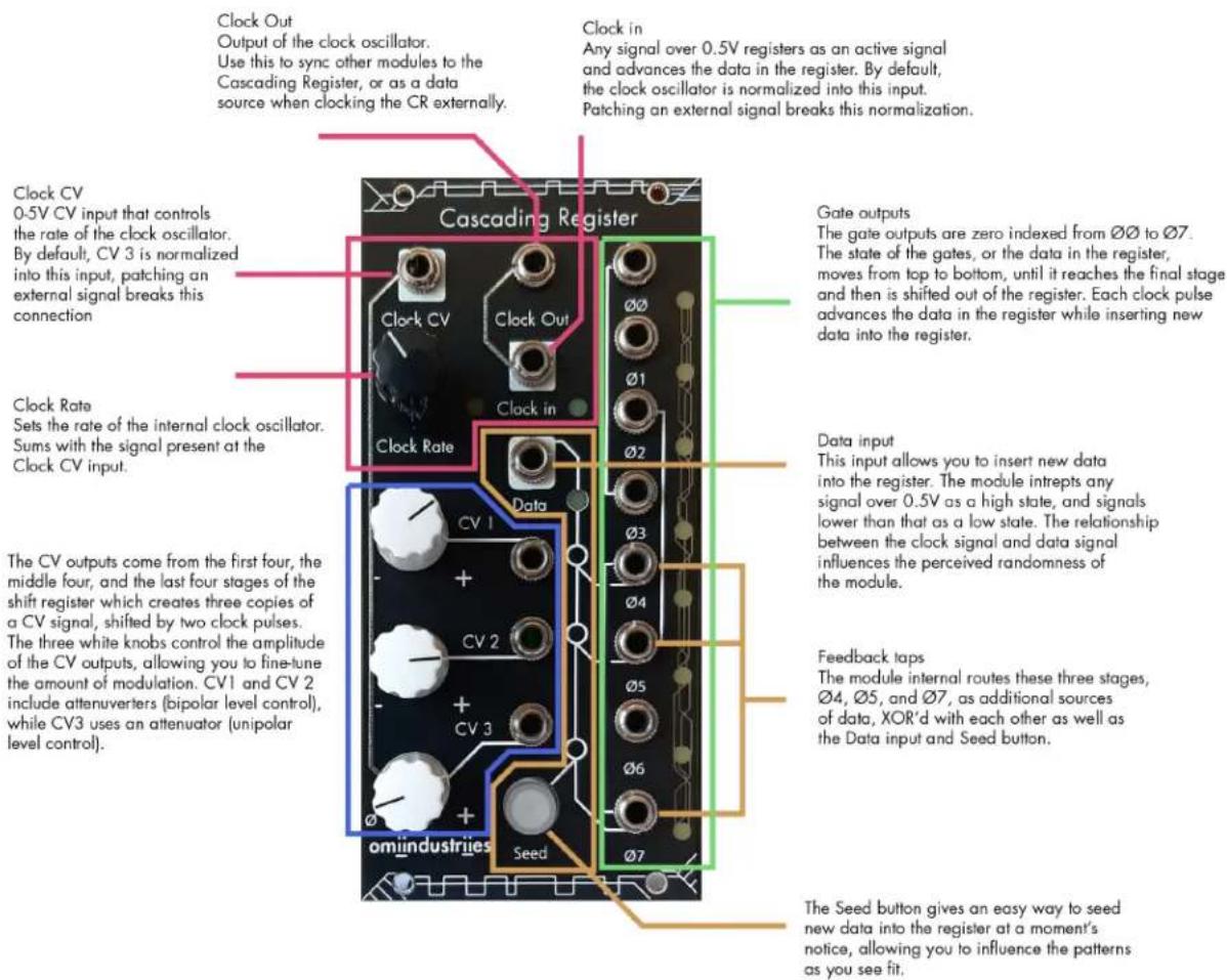
Clock Out Output of the clock oscillator. Use this to sync other modules to the Cascading Register, or as a data source when clocking the CR externally. Clock in Any signal over 0.5V registers as an active signal and advances the data in the register. By default, the clock oscillator is normalized into this input. Patching an external signal breaks this normalization. Clock CV 0-5V CV input that controls the rate of the clock oscillator. By default, CV 3 is normalized into this input, patching an external signal breaks this connection Clock Rate Sets the rate of the internal clock oscillator. Sums with the signal present at the Clock CV input. Cascading Register Clock CV Clock Out Clock In Clock Rate Data CV 1 + - CV 2 + - CV 3 + - omindustries Seed Ø7Internalandexternal clocks
Inadditiontoashiftregister,the CascadingRegisterincludesan internalvoltage-controlledclock oscillator.Thisclockoscillatorruns atsub-audiotolowaudioratesand featuresCVcontrolovertherate. Withnocablepresentattheclock inputjack,theclocksignalis normalizedintotheinputclock.A secondnormalizationroutesthe outputoftheCV3intotheCVinput oftheclockoscillator. Thiscreatesa self-modulatingfeedbackloop withouttheneedtopatchanything.
Sometimesyouwantafree-running
clockedmodulationsource,butothetimesyoumayfeeltheneedtosynctheCascading Register to an external clock signal. Patching into the clock input overrides the internal clock. Goodsourcesofclocksorgatesignalsinmodularsynthesisincludeclockdividers/multipliers, squarewaveLFOs,sequencers,touchcontrollers,oranotherrandomgatesource.Clockingthe CRfromasharedexternalclocksourceisagreatwaytogetyourCVandgatesinsyncwiththe restofyourpatch.
If youdodecidetoclocktheCascadingRegisterfromanexternalclocksource,theinternal clockisstillactive.Becausethisismodularsynthesis,youcanpatchthatclockelsewherein yoursystemorbackintotheCascadingRegister.SergeTcherepnin'sfamousSergemodular synthesizerspioneeredatechniquecalledpatchprogramming.Patchprogrammingbasically comesdowntochangingthefunctionofamodulebypatchingoneoftheoutputsdirectlyback intooneoftheinputsonthesamemodule.Usingthisconcept,wecanpatchtheoutputofthe clockoscillatorintotheexternaldatainput,turningitintoadatasource.Thisfreesupothergate signalsinyoursystemandallowstheCascadingRegistertofunctionasafully-fledgedclocked pseudo-randommodulationandtimingsourcewithonlyoneexternalclocksignalneeded.
While the internal clock runs at sub-audiotolowaudiorates, the Cascading Register accepts signals from sub-audio all the way into videorate. At audiorate, the CR becomes anoise generator with both stepped analog and digital noise outputs coming from the CV and gate outputs respectively.
When clocked at videorates, it creates pseudo-random noise and textures. Running one of the CV output stomodulate the frequency of the video oscillator is a great way to add an additional
layerofcomplexitytothepatterns.Itworksbestwithvideooscillators,withrampsandactual videosignalsgivingmixedresults,butexperimentwithdifferentinputsandseewhatyouget.
text_image
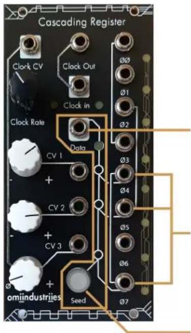
Cascading Register Clock CV Clock Out 00 01 Clock in Clock Rate Data CV 1 + CV 2 + CV 3 + omiindustries Seed Ø2 Ø3 Ø4 Ø5 Ø6 Ø7Data input
This input allows you to insert new data into the register. The module intrepts any signal over 0.5V as a high state, and signals lower than that as a low state. The relationship between the clock signal and data signal influences the perceived randomness of the module.
Feedback taps
The module internal routes these three stages, ∅4, ∅5, and ∅7, as additional sources of data, XOR'd with each other as well as the Data input and Seed button.
The Seed button gives an easy way to seed new data into the register at a moment's notice, allowing you to influence the patterns as you see fit.
Datainputandseed button
Ashiftregisterincludesadatainput topassinformationintotheregister. TheSeedbuttongivesaneasyway toseednewdataintotheregisterata moment'snotice,allowingyouto influencethepatternsasyouseefit. Thisisparticularlyusefulwhenfirst turningonthemodule,asallthe stagesmaybeactiveorinactive. Pressingthebuttonentersnewdata intotheregister,andyoushouldsee onandoffstagesmovingfromthetop tothebottomofthemodule.TheCR alsoincludesanexternaldatainput, allowingyoutopatchexternaldata
intothemodule.Usually,thistakestheformofagatesignal,butanysignalover0.5Vwill registerasahighstateandanysignalbelowthat(includingnegativevoltages)registersasa lowstate.
InadditiontotheexternaldatainputandtheSeedbutton, datacomesfromthreeofthestages oftheshiftregister, (∅4, ∅5, and ∅7), asindicatedbythewhitelinesonthepanel. Thisaddition ofthefeedbackstagesmeansthemodulegetsdatafromseveralsourcesandallowsforawider rangeofexternaldatasourcestobeusedwiththemodule.
CVoutputs
The CascadingRegister include three CV outputs derived from the state of the stages of the shift register. CV1 is determined by ∅∅, ∅1, ∅2, and ∅3. While ∅2, ∅3, ∅4, and ∅5 correspond to CV2 and ∅4, ∅5, ∅6, and ∅7 makeup CV3. This grouping of stages creates three copies of the same data shifted by twoclock pulses.
CV 1
CV 2
CV 3

natural_image
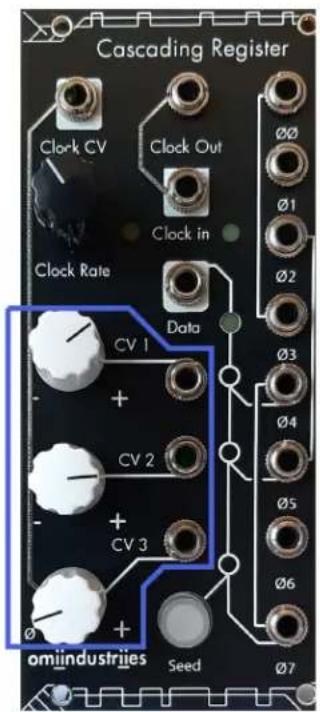
Abstract geometric pattern with interlocking lines and dashed grid lines (no text or symbols)The CV outputs come from the first four, the middle four, and the last four stages of the shift register which creates three copies of a CV signal, shifted by two clock pulses. The three white knobs control the amplitude of the CV outputs, allowing you to fine-tune the amount of modulation. CV1 and CV2 include attenuators (bipolar level control), while CV3 uses an attenuator (unipolar level control).
text_image
Cascading Register Clock CV Clock Out Clock in Clock Rate Data CV 1 + - CV 2 + - CV 3 + - omindustries Seed Ø0 Ø1 Ø2 Ø3 Ø4 Ø5 Ø6 Ø7ThethreewhiteknobscontroltheamplitudeoftheCVoutputs,allowingyoutofine-tunethe amountofmodulation.CV1and2haveassociatedattenuverters,whileCV3includesan attenuator.Attenuatorsgofromoffwhenthecontrolisallthewaycounterclockwise,andatfull amplitudewhenthecontrolisallthewayclockwise.Attenuverters,ontheotherhand,areoff whencentered.Turningtheknobclockwisefromthecenterincreasesthamplitudepositively whileturningcounterclockwisefromthecenterincreasesthamplitudenegatively.Increasing negativelymaysoundcounterintuitive,butifyoupatchintothepitchofanoscillator,the negativevoltagewillcausethepitchoftheoscillatortodecreaseratherthanincrease.(Note, notallmodulesacceptorregisternegativevoltage,soifitseemslikethenegativevoltageisn't doinganything,refertoyourmodule'smanual.)
Gateoutputs
The CascadingRegister includes gate outputsforeach of the eight stages of the shift register, labeled to 7. The outputs are binary gates signals, meaning they only have two states, on with an amplitude of +5V or off,0V. Gates fill a variety of uses within a modular synthesizer but are primarily used for timing information. This includes firing off an envelope, triggering as sample, advancing a sequence, generating a new random value from another random module.
Makingrhythmswiththegate outputsisfairlystraightforward. Thepositionfrom∅∅to∅7 determineswhereinthebarthebeatsland.Soifyoupatchtoakickdrumwith∅∅andasnare drumsoundwith∅2,yougetacallandresponseofthetwosoundsshiftedbytwoclockpulses. Combiningseveralofthestageoutputswithalogicmodulesuchastheomiindustriieslllyana allowsyoutoincreasethecomplexityofyourrhythms.
However, gates are not just fortiming, they also come in handy as modulations. This works especially well with percussives sounds sources and drum module that benefit from sudden and stepped changes in parameters. Attenuating or tenuverting the gates will help you fine-tun the amount of modulation from a 5V signal to am more incremental change.

text_image
Cascading Register Clock CV Clock Out Clock in Clock Rate Data CV 1 + CV 2 + CV 3 - + omindustries Seed ØØ Ø1 Ø2 Ø3 Ø4 Ø5 Ø6 Ø7Gate outputs
The gate outputs are zero indexed from 00 to 07. The state of the gates, or the data in the register, moves from top to bottom, until it reaches the final stage and then is shifted out of the register. Each clock pulse advances the data in the register while inserting new data into the register.
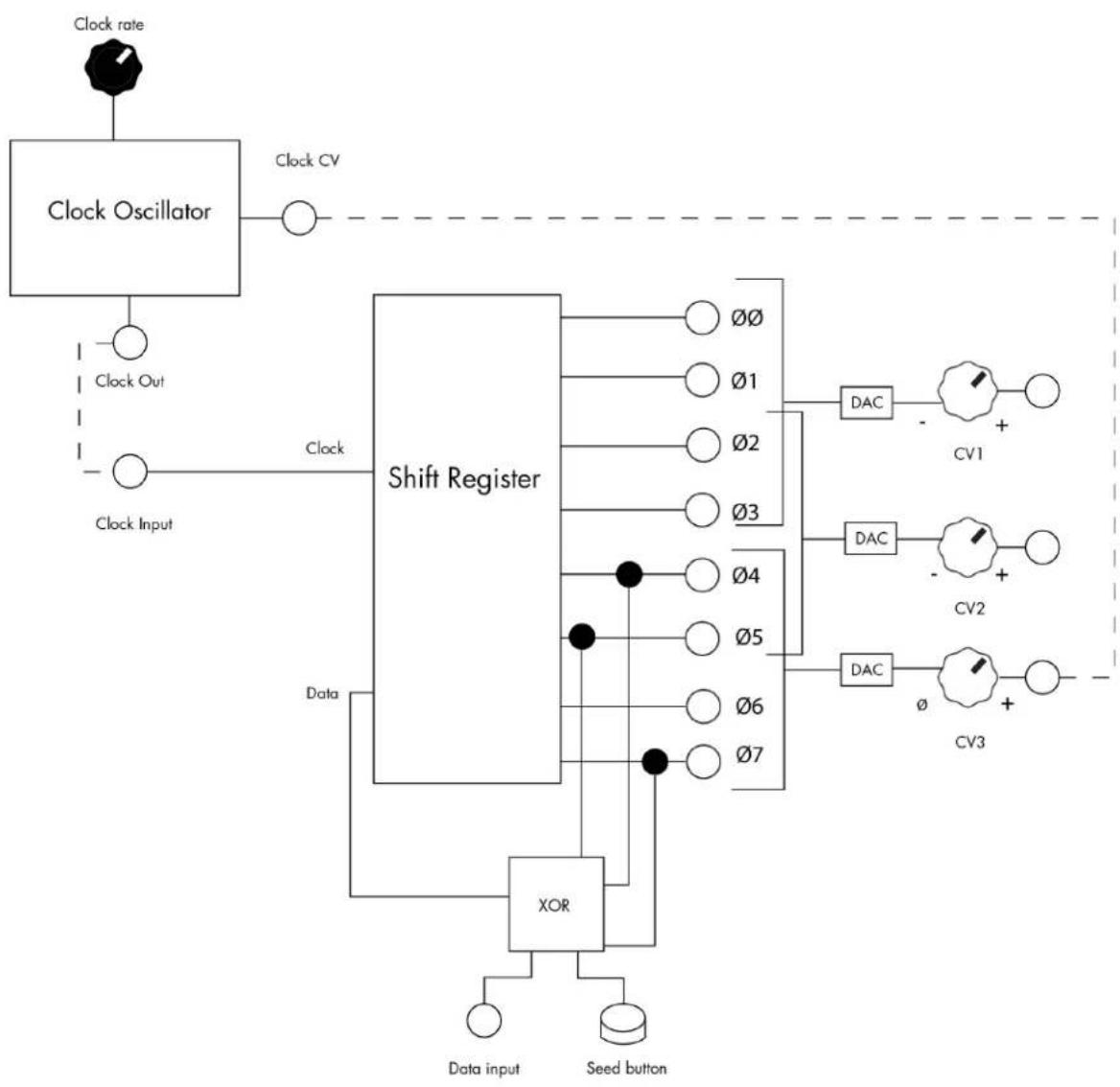
flowchart
graph TD
    A["Clock rate"] --> B["Clock Oscillator"]
    B --> C["Clock CV"]
    D["Clock Input"] --> E["Shift Register"]
    E --> F["Data"]
    F --> G["XOR"]
    G --> H["Data input"]
    G --> I["Seed button"]
    J["Clock Out"] --> K["Clock"]
    L["Clock"] --> M["Shift Register"]
    M --> N["00"]
    M --> O["01"]
    M --> P["02"]
    M --> Q["03"]
    M --> R["04"]
    M --> S["05"]
    M --> T["06"]
    M --> U["07"]
    V["DAC"] --> W["CV1"]
    X["DAC"] --> Y["CV2"]
    Z["DAC"] --> AA["CV3"]