SuperServer F619P2-FT+ - Server Supermicro - Free user manual and instructions
Find the device manual for free SuperServer F619P2-FT+ Supermicro in PDF.

User questions about SuperServer F619P2-FT+ Supermicro
0 question about this device. Answer the ones you know or ask your own.
Ask a new question about this device
Download the instructions for your Server in PDF format for free! Find your manual SuperServer F619P2-FT+ - Supermicro and take your electronic device back in hand. On this page are published all the documents necessary for the use of your device. SuperServer F619P2-FT+ by Supermicro.
USER MANUAL SuperServer F619P2-FT+ Supermicro
natural_image
Front view of a rack-mounted server rack with multiple drive bays and ports (no visible text or labels)USER'S MANUAL
Revision 1.0
The information in this User's Manual has been carefully reviewed and is believed to be accurate. The vendor assumes no responsibility for any inaccuracies that may be contained in this document, and makes no commitment to update or to keep current the information in this manual, or to notify any person or organization of the updates. Please Note: For the most up-to-date version of this manual, please see our website at www.supermicro.com.
Super Micro Computer, Inc. ("Supermicro") reserves the right to make changes to the product described in this manual at any time and without notice. This product, including software and documentation, is the property of Supermicro and/or its licensors, and is supplied only under a license. Any use or reproduction of this product is not allowed, except as expressly permitted by the terms of said license.
IN NO EVENT WILL Super Micro Computer, Inc. BE LIABLE FOR DIRECT, INDIRECT, SPECIAL, INCIDENTAL, SPECULATIVE OR CONSEQUENTIAL DAMAGES ARISING FROM THE USE OR INABILITY TO USE THIS PRODUCT OR DOCUMENTATION, EVEN IF ADVISED OF THE POSSIBILITY OF SUCH DAMAGES. IN PARTICULAR, SUPER MICRO COMPUTER, INC. SHALL NOT HAVE LIABILITY FOR ANY HARDWARE, SOFTWARE, OR DATA STORED OR USED WITH THE PRODUCT, INCLUDING THE COSTS OF REPAIRING, REPLACING, INTEGRATING, INSTALLING OR RECOVERING SUCH HARDWARE, SOFTWARE, OR DATA.
Any disputes arising between manufacturer and customer shall be governed by the laws of Santa Clara County in the State of California, USA. The State of California, County of Santa Clara shall be the exclusive venue for the resolution of any such disputes. Supermicro's total liability for all claims will not exceed the price paid for the hardware product.
FCC Statement: This equipment has been tested and found to comply with the limits for a Class A digital device pursuant to Part 15 of the FCC Rules. These limits are designed to provide reasonable protection against harmful interference when the equipment is operated in a commercial environment. This equipment generates, uses, and can radiate radio frequency energy and, if not installed and used in accordance with the manufacturer's instruction manual, may cause harmful interference with radio communications. Operation of this equipment in a residential area is likely to cause harmful interference, in which case you will be required to correct the interference at your own expense.
California Best Management Practices Regulations for Perchlorate Materials: This Perchlorate warning applies only to products containing CR (Manganese Dioxide) Lithium coin cells. "Perchlorate Material-special handling may apply. See www.dtsc.ca.gov/hazardouswaste/perchlorate".

WARNING: This product can expose you to chemicals including lead, known to the State of California to cause cancer and birth defects or other reproductive harm. For more information, go to www.P65Warnings.ca.gov.
The products sold by Supermicro are not intended for and will not be used in life support systems, medical equipment, nuclear facilities or systems, aircraft, aircraft devices, aircraft/emergency communication devices or other critical systems whose failure to perform be reasonably expected to result in significant injury or loss of life or catastrophic property damage. Accordingly, Supermicro disclaims any and all liability, and should buyer use or sell such products for use in such ultra-hazardous applications, it does so entirely at its own risk. Furthermore, buyer agrees to fully indemnify, defend and hold Supermicro harmless for and against any and all claims, demands, actions, litigation, and proceedings of any kind arising out of or related to such ultra-hazardous use or sale.
Manual Revision 1.0
Release Date: October 03, 2019
Unless you request and receive written permission from Super Micro Computer, Inc., you may not copy any part of this document. Information in this document is subject to change without notice. Other products and companies referred to herein are trademarks or registered trademarks of their respective companies or mark holders.
Copyright © 2019 by Super Micro Computer, Inc.
All rights reserved.
Printed in the United States of America
Preface
About this Manual
This manual is written for professional system integrators and PC technicians. It provides information for the installation and use of the FatTwin F619P2-FT+. Installation and maintenance should be performed by experienced technicians only.
Please refer to the F619P2-FT+ server specifications page on our website for updates on supported memory, processors and operating systems (http://www.supermicro.com).
Notes
For your system to work properly, please follow the links below to download all necessary drivers/utilities and the user's manual for your server.
• Supermicro product manuals: http://www.supermicro.com/support/manuals/
- Product drivers and utilities: https://www.supermicro.com/wftp/
- Product safety info: http://www.supermicro.com/about/policies/safety_information.cfm
If you have any questions, please contact our support team at: support@supermicro.com
This manual may be periodically updated without notice. Please check the Supermicro website for possible updates to the manual revision level.
Warnings
Special attention should be given to the following symbols used in this manual.

Warning! Indicates important information given to prevent equipment/property damage or personal injury.

Warning! Indicates high voltage may be encountered when performing a procedure.
Contents
Chapter 1 Introduction
1.1 Overview....9
1.2 Unpacking the System 9
1.3 FatTwin: System Notes ....10
Nodes....10
System Power....10
Firmware Integrity/System Security ....10
1.4 System Features .... 11
1.5 Server Chassis Features....12
Node Controls 12
Front Features....13
Rear Features....14
1.6 Motherboard Layout....15
Quick Reference Table....16
Chapter 2 Server Installation
2.1 Overview....18
2.2 Preparing for Setup....18
Choosing a Setup Location....18
Rack Precautions....18
Server Precautions....19
Rack Mounting Considerations....19
Ambient Operating Temperature....19
Airflow 19
Mechanical Loading....19
Circuit Overloading....20
Reliable Ground....20
2.3 Rack Mounting Instructions....21
Identifying the Sections of the Rack Rails....22
Adjusting the Rails ....22
Installing the Rails on a Rack....23
Chassis Installation 24
Chapter 3 Maintenance and Component Installation
3.1 Removing Power....25
3.2 Chassis Components ....26
Installing and Removing the Node Drawers ....26
Removing Nodes from the Chassis....27
Removing the Cover from the Node....27
Node Configurations....28
Overview of the Node....28
F418IF3-R2K20BP Node Layout....28
Nodes and Associated Hard Drives....29
Installing and Removing 2.5" Hard Drives....29
Drive Carrier Indicators....31
Hot-Swap for NVMe Drives ....31
Checking the Temperature of an NVMe Drive ....32
Installing Expansion Cards....33
Assembling the PCI-E Slot Bracket Assembly 34
Installing Air Shrouds 36
Air Shrouds....36
Removing and Installing System Fans ....37
Removing and Installing External System Fans....37
Replacing the Power Supplies ....38
Power Supply Replacement....38
3.3 Motherboard Components....39
Processor and Heatsink Installation....39
The Processor....39
Overview of the Processor Socket Assembly 40
Overview of the Processor Heatsink Module....41
Preparing the CPU Socket for Installation....42
Removing the Dust Cover from the CPU Socket 42
Attaching the Processor to the CPU/Heatsink Carrier....43
Attaching the CPU/Carrier Assembly to the Passive Heatsink to Form the Processor
Heatsink Module (PHM)....44
Installing the Processor Heatsink Module (PHM) 45
Removing the Processor Heatsink Module (PHM)....46
Memory Support and Installation....47
ESD Precautions....47
Precautions....47
Introduction to Intel® Optane DC Persistent Memory 47
Memory Support 47
Memory Installation Sequence 48
General Memory Population Requirements ....49
DIMM Installation ....51
DIMM Module Removal....51
Motherboard Battery ....52
Chapter 4 Motherboard Connections
4.1 Power Connections ....53
4.2 Headers and Connectors ....54
4.3 Front I/O Ports....57
4.4 Jumpers....60
Explanation of Jumpers....60
4.5 LED Indicators....61
Chapter 5 ofware
5.1 Microsoft Windows OS Installation....63
5.2 Driver Installation....65
5.3 SuperDoctor ^® 5....66
5.4 IPMI 66
Chapter 6 UEFI BIOS
6.1 Introduction....67
Starting the Setup Utility 67
6.2 Main Setup 68
6.3 Advanced Setup Configurations....70
6.4 Event Logs ....101
6.5 IPMI 103
6.6 Security Settings ....106
6.7 Boot Settings....109
6.8 Save & Exit....112
Appendix A BIOS Error Codes
Appendix B Standardized Warning Statements for AC Systems
Appendix C System Specifications
Appendix D UEFI BIOS Recovery
Appendix E BSMI Safety Warnings
Appendix F CPU-Based RAID for NVMe
Contacting Supermicro
Headquarters
Address: Super Micro Computer, Inc.
980 Rock Ave.
San Jose, CA 95131 U.S.A.
Tel: +1 (408) 503-8000
Fax: +1 (408) 503-8008
Email: marketing@supermicro.com (General Information)
support@supermicro.com (Technical Support)
Website: www.supermicro.com
Europe
Address: Super Micro Computer B.V.
's-Hertogenbosch, The Netherlands
Tel: +31 (0) 73-6400390
Fax: +31 (0) 73-6416525
Email: sales@supermicro.nl (General Information)
support@supermicro.nl (Technical Support)
rma@supermicro.nl (Customer Support)
Website: www.supermicro.nl
Asia-Pacific
Address: Super Micro Computer, Inc.
3F, No. 150, Jian 1st Rd.
Zhonghe Dist., New Taipei City 235
Taiwan (R.O.C)
Tel: +886-(2) 8226-3990
Fax: +886-(2) 8226-3992
Email: support@supermicro.com.tw
Website: www.supermicro.com.tw
Chapter 1
Introduction
1.1 Overview
This chapter provides a brief outline of the functions and features of the F619P2-FT+. The F619P2-FT+ is based on the X11DPFF-SNR motherboard and the F418IF3-R2K20BP chassis. This FatTwin system includes eight motherboard tray nodes in the chassis.
In addition to the motherboard and chassis, several important parts that are included with the system are listed below.
| Main Parts List | ||
| Description Part Number Quantity | ||
| 1U Passive CPU heatsinks with a Narrow Retention Mechanism (NRM) | SNK-P0067PS | 8 |
| 1U Passive CPU heatsinks with a 17-mm wide side air channel and Narrow Retention Mechanism | SNK-P0067PSC 8 | |
| F418IF3 mylar air shrouds (2-pcs) | MCP-310-41812-0B or MCP-310-41813-0B | 1 |
| 1U redundant power supplies | PWS-2K20A-1R (2200 Watt) or PWS-2K04A-1R (2000 Watt) | 4 |
| Fat twin F418 / F424 static rail set support 28-33.5 inch depth rail | MCP-290-41803-0N | 1 |
| Riser cards RSC-P-6 8 | ||
| Riser cards RSC-R1UF-E16R 8 | ||
1.2 Unpacking the System
Inspect the box the SuperServer F619P2-FT+ was shipped in and note if it was damaged in any way. If any equipment appears damaged, please file a damage claim with the carrier who delivered it.
Decide on a suitable location for the rack unit that will hold the server. It should be situated in a clean, dust-free area that is well ventilated. Avoid areas where heat, electrical noise and electromagnetic fields are generated. It will also require a grounded AC power outlet nearby.
Be sure to read the precautions and considerations noted in Appendix B.
1.3 FatTwin: System Notes
As a FatTwin configuration, the FatTwin F619P2-FT+ is a unique server system. With eight system boards incorporated into a single chassis acting as eight separate nodes, there are several points you should keep in mind.
Nodes
Each of the eight serverboards act as a separate node in the system. As independent nodes, each may be powered off and on without affecting the others. In addition, each node is a hot-swappable unit that may be removed from the chassis. The nodes are connected to the server backplane by means of an adapter card.
Note: A guide pin is located between the upper and lower nodes on the inner chassis wall. This guide pin also acts as a "stop" when a node is fully installed. If too much force is used when inserting a node this pin may break off. Take care to slowly slide a node in until you hear the "click" of the locking tab seating itself.
System Power
Four 2000 or 2200 Watt power supplies are used to provide the power for all serverboards. Each serverboard however, can be shut down independently of the others with the power button on its own control panel.
Firmware Integrity/System Security
The F619P2-FT+ system has RoT (Root of Trust) support to protect firmware security by detecting critical data corruption, and restoring platform integrity.
1.4 System Features
The following table provides you with an overview of the main features of the F619P2-FT+. Please refer to Appendix C for additional specifications.
| System Features |
| Motherboard |
| X11DPFF-SNR |
| Chassis |
| F418IF3-R2K20BP |
| CPU |
| Dual 81xx/61xx/51xx/41xx/31xx and 82xx/62xx/52xx/42xx/32xx processor which offer 2 UPI (UltraPath Interconnect) of up to 10.4GT/sNote: Both CPUs need to be installed for full access to the PCI-E slots, DIMM slots, and onboard controllers. Refer to the block diagram on page 16 to determine which slots or devices may be affected. |
| Socket Type |
| Socket P0 |
| Memory |
| Integrated memory controller embedded in the processor supports up to 1.5 TB of 3DS Load Reduced DIMM (3DS LRDIMM), Load Reduced DIMM (LRDIMM), 3DS Registered DIMM (3DS RDIMM), Registered DIMM (RDIMM), and NVDIMM DDR4 (288-pin) ECC memory of 2933/2666/2400/2133 MHz in 12 slots |
| Chipset |
| C621 chipset |
| Expansion Slots |
| The X11DPFF-SNR motherboard has the following expansion slots available.One PCI-E 3.0 x16 slot supported by CPU 1 (JPCIE4)One PCI-E 3.0 x8 slot supported by CPU 1 (Slot2)One PCI-E 3.0 x16 Super I/O Module slot supported by CPU 1 (SIOM)Two NVMe for PCI-E high-speed storage devices with option for two more drives, supported by CPU2 (PN-NVMe 0/1/2/3)One Riser card header for SDD1 devicesNote: only two slots are available in the front for use. |
| Hard Drives |
| The F619P2-FT+ has either two or four 2.5" SATA3 or NVMe drives |
| Power |
| Four 2000 or 2200 Watt redundant power supplies |
| Cooling |
| Up to eight 8-cm hot-swappable 13.5K RPM cooling fans shared by the system's eight serverboard nodes |
| Form Factor |
| Proprietary: 18.73" (L) x 8.54" (W) (475.74 mm x 216.92 mm) |
| Dimensions |
| (WxHxD) 17.63 x 6.96 x 29 in. (448 x 177 x 737 mm) |
1.5 Server Chassis Features
Node Controls
Each node has a power button and UID LED located with I/O ports on the front of the node. See Chapter 4 for details on the node controls.

natural_image
Diagram of a server rack with internal components and a close-up view of the internal circuit board (no text or labels)Figure 1-1. Node Controls
| Node Controls | ||
| Item Feature Description | ||
| 1 Power | Button | The main power button on each of the eight control panels is used to apply or remove power from the power supply to each of the eight systems in the chassis. Turning off system power with this button removes the main power, but keeps standby power supplied to the system. Therefore, you must unplug system before servicing. The power button has a built-in LED which will turn green when the power is on. |
| 2 UID LED | When used with a UID compatible serverboard, the UID indicator is used to turn on or off the blue light function of the LED. This is built into the front side of the UID button and at the rear end of each serverboard node, for those motherboards which support it. Once the blue light is activated, the unit can be easily located in very large racks and server banks. | |
Front Features
The F418IF3-R2K20BP is a 4U chassis with eight hot-swap server nodes. See the illustration below for the features included on the front of the chassis.
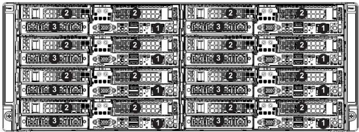
text_image
Diagram of a server rack with labeled ports and numbered connectors, showing internal layout and port connections.Figure 1-2. Chassis Front View
| Front Chassis Features | ||
| Item Feature Description | ||
| 1 Node | Ports and Controls (8) | See the section for node controls above for details, and see chapter 4 for node port details. |
| 2 Expansion | Card Slots | Each node has two bays in the front for low-profile expansion cards.See chapter 3 for details on the expansion cards. |
| 3 SIOM | module See Chapter 4 for details | on the SIOM modules. |
Rear Features
The illustration below shows the features included on the rear of the chassis.

text_image
Technical diagram of a multi-chamber electronic module with labeled components and mounting pointsFigure 1-3. Chassis Rear View
| Rear Chassis Features | ||
| Item Feature Description | ||
| 1 Power Supply Four (4) redundant 2000 or 2200 Watt power supplies | ||
| 2 Rear Fan | The chassis has eight rear fans for cooling. These are hot-swappable and can be replaced without powering down the system. | |
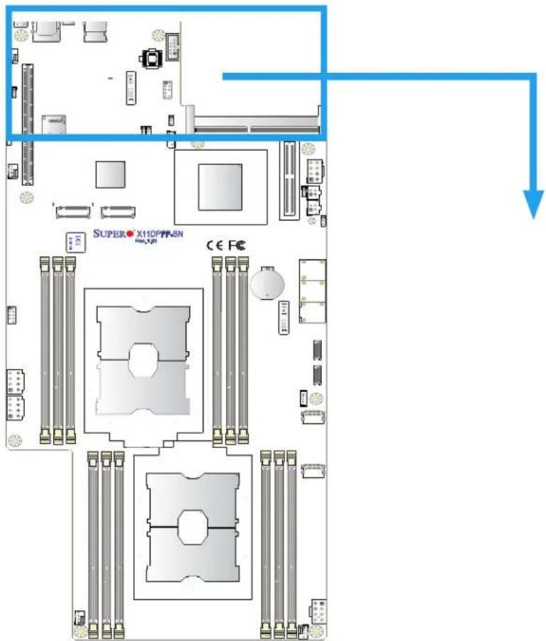
1.6 Motherboard Layout
Below is a layout of the X11DPFF-SNR with jumper, connector and LED locations shown. See the table on the following page for descriptions. For detailed descriptions, pinout information and jumper settings, refer to Chapter 4.
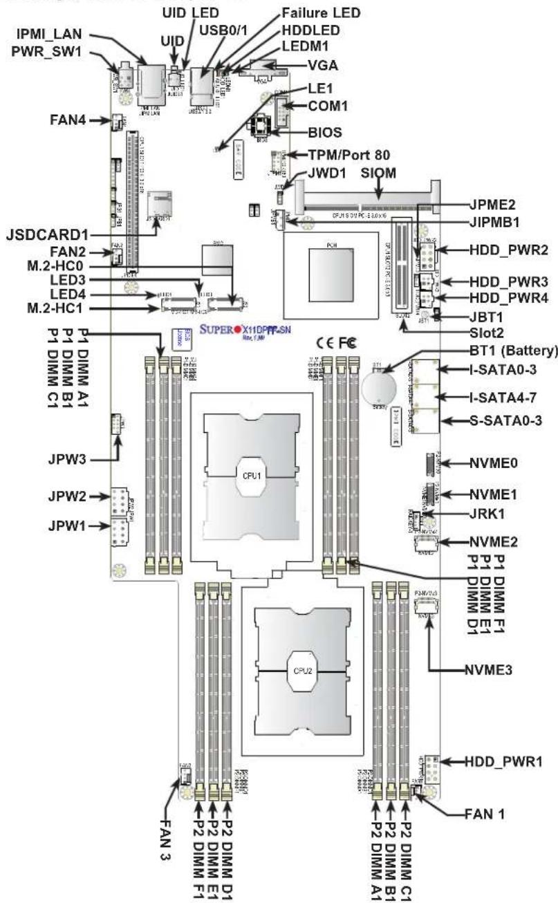
text_image
IPMI_LAN PWR_SW1 FAN4 JSDCARD1 FAN2 M.2-HC0 LED3 LED4 M.2-HC1 P1 DIMM A1 P1 DIMM B1 C1 JPW3 JPW2 JPW1 FAN 3 UID LED USB0/1 Failure LED HDDLED LEDM1 VGA LE1 COM1 BIOS TPM/Port 80 JWD1 SIOM JPM2 JIPMB1 HDD_PWR2 HDD_PWR3 HDD_PWR4 JBT1 Slot2 BT1 (Battery) I-SATA0-3 I-SATA4-7 S-SATA0-3 NVME0 NVME1 JRK1 NVME2 P1 DIMM F1 DIMM E1 P2 DIMM C1 P2 DIMM B1 P2 DIMM A1 CPU1 CPU2 FAN 1 HDD_PWR1Figure 1-4. Motherboard Layout
Notes:
• See Chapter 4 for detailed information on jumpers, I/O ports, and JF1 front panel connections.
- Jumpers/LED indicators not indicated are used for internal testing only.
Quick Reference Table
Jumper Description Default Setting
| JBT1 CMOS Clear Open (Normal) |
| JPME2 ME Manufacturing Mode Pins 1-2 (Normal) |
| JWD1 Watch Dog Timer Enable Pins 1-2 (Reset) |
Connector Description
| Battery (BT1) Onboard CMOS battery | |
| CPU1 Slot1 PCI-E (JPCEI4) PCI-E 3.0 x16 slot supported by CPU1 | |
| CPU1 Slot2 PCI-E (Slot 2) PCI-E 3.0 x8 slot supported by CPU1 | |
| CPU1 SIOM (SIOM) PCI-E 3.0 x16 Super IO Module (SIOM) slot supported by CPU1 | |
| COM (JCOM1) | COM Port1 |
| FAN1-FAN4 | System/CPU cooling fan headers |
| IPMB (JIPMB1) | System Management Bus header for IPMI 2.0 |
| IPMI_LAN (JIPMILAN) | Dedicated IPMI LAN port supported by BMC (Baseboard Management Controller) |
| HDD_PWR1/2 | 8-pin power connectors (1/2) used for HDD devices |
| HDD_PWR3/4 | 4-pin power connectors (3/4) used for HDD devices |
| JPW1/JPW2 (PB PWR1/2) | 12-V 8-pin power connectors for ADPs (via cables connected to power adaptor cards) |
| JPW3 (PB MISC) | 8-pin auxiliary power connector for ADP (via a cable connected to a power adaptor card) |
| JRK1 | NVMe RAID Key header |
| JSDCARD1 | BMC SD card header |
| M.2-HC0/M.2-HC1 (J30/J31) | PCI-E/SATA hybrid M.2 slots (M.2 slots with both PCI-E and SATA support) |
| PN-NVMe01/2/3 (NVME0/1/2/3) | Onboard NVMe connectors used for PCI-E high-speed storage devices supported by CPU2 |
| PWR (PWR_SW1) | Front panel power (on/off) switch |
| (I-)SATA0-3, 4-7 | SATA 3.0 connections supported by Intel PCH (I-SATA 0-3, 4-7) |
| (S-)SATA0-3 | SATA 3.0 ports supported by Intel PCH (S-SATA 0-3) |
| TPM/Port80 (JTPM1) | Trusted Platform Module (TPM)/Port 80 connector |
| USB0/1 (JUSB1) | Front panel USB 3.0 ports 0/1 |
| UID (JUID1) | Unit Identifier (UID) button |
| VGA (JVGA1) | VGA port |
| LED | Description | Status |
| FAILURE_LED1 | Overheat/Fan Fail LED | Solid Red: OH/Fan Failure |
| HDD_LED1 | HDD Activity LED | Blinking Green: HDD Active |
| LE1 | CPLD Heartbeat LED | Blinking Green: CPLD Normal |
| LED3 | M.2 LED (for M.2-HC0-J30) | Blinking Green: M.2-HC0 Active |
| LED4 | M.2 LED (for M.2-HC1-J31) | Blinking Green: M.2-HC1 Active |
| LEDM1 | BMC Heartbeat LED | Blinking Green: BMC Normal |
| UID_LED1 | UID LED | Solid Blue: Unit Identified |

flowchart
graph TD
    subgraph DDR4
        A["DDR4 2133/2666"] -->|6CH| B["Processor"]
        B -->|UPI| C["Processor"]
        C -->|16CH| D["DDR4 2133/2666"]
        B -->|P0 P1 P2| E["Processor"]
        E -->|UPI| C
    end

    subgraph PCH
        F["PCI-E X1 G3"] -->|6.0 Gb/S| G["PCI-E X16 G3"]
        H["PCI-E X1 G4"] -->|6.0 Gb/S| I["PCI-E X16 G3"]
        J["PCI-E X1 G5"] -->|6.0 Gb/S| K["PCI-E X16 G3"]
        L["PCI-E X1 G6"] -->|6.0 Gb/S| M["PCI-E X16 G3"]
        N["PCI-E X1 G7"] -->|6.0 Gb/S| O["PCI-E X16 G3"]
        P["PCI-E X1G"] -->|6.0 Gb/S| Q["PCI-E X16 G3"]
        R["PCI-E X1G"] -->|6.0 Gb/S| S["PCI-E X16 G3"]
        T["PCI-E X1G"] -->|6.0 Gb/S| U["PCI-E X16 G3"]
        V["PCI-E X1G"] -->|6.0 Gb/S| W["PCI-E X16 G3"]
        X["PCI-E X1G"] -->|6.0 Gb/S| Y["PCI-E X16 G3"]
        Z["PCI-E X1G"] -->|6.0 Gb/S| AA["PCI-E X16 G3"]
        AB["PCI-E X1G"] -->|6.0 Gb/S| AC["PCI-E X16 G3"]
        AD["PCI-E X1G"] -->|6.0 Gb/S| AE["PCI-E X16 G3"]
        AF["PCI-E X1G"] -->|6.0 Gb/S| AG["PCI-E X16 G3"]
        AH["PCI-E X1G"] -->|6.0 Gb/S| AI["PCI-E X16 G3"]
        AJ["PCI-E X1G"] -->|6.0 Gb/S| AK["PCI-E X16 G3"]
        AL["PCI-E X1G"] -->|6.0 Gb/S| AM["PCI-E X16 G3"]
        AN["PCI-E X1G"] -->|6.0 Gb/S| AO["PCI-E X16 G3"]
        AP["PCI-E X1G"] -->|6.0 Gb/S| AQ["PCI-E X16 G3"]
        AR["PCI-E X1G"] -->|6.0 Gb/S| AS["PCI-E X16 G3"]
        AT["PCI-E X1G"] -->|6.0 Gb/S| AU["PCI-E X16 G3"]
        AV["PCI-E X1G"] -->|6.0 Gb/S| AW["PCI-E X16 G3"]
        AX["PCI-E X1G"] -->|6.0 Gb/S| AY["PCI-E X16 G3"]
        AZ["PCI-E X1G"] -->|6.0 Gb/S| BA["PCI-E X16 G3"]
        BB["PCI-E X1G"] -->|6.0 Gb/S| BC["PCI-E X16 G3"]
        BD["PCI-E X1G"] -->|6.0 Gb/S| CA["PCI-E X16 G3"]
        CB["Mini SAS HD"] -->|6.0 Gy/S| AD
    end

    subgraph PCH
        AD["PCH"]
    end

    subgraph PCH
        AD
    end

    subgraph PCH
        AD
    end

    subgraph PCH
        AD
    end

    subgraph PCH
        AD
    end

    subgraph PCH
        AD
    end

    subgraph PCH
        AD
    end

    subgraph PCH
        AD
    end

    subgraph PCH
        AD
    end

    subgraph PCH
        AD
    end
Figure 1-5. System Block Diagram
Note: This is a general block diagram and may not exactly represent the features on your motherboard. See the System Specifications appendix for the actual specifications of your motherboard.
Chapter 2
Server Installation
2.1 Overview
This chapter provides advice and instructions for mounting your system in a server rack. If your system is not already fully integrated with processors, system memory etc., refer to Chapter 4 for details on installing those specific components.
Caution: Electrostatic Discharge (ESD) can damage electronic components. To prevent such damage to PCBs (printed circuit boards), it is important to use a grounded wrist strap, handle all PCBs by their edges and keep them in anti-static bags when not in use.
2.2 Preparing for Setup
The box in which the system was shipped should include the rackmount hardware needed to install it into the rack. Please read this section in its entirety before you begin the installation.
Choosing a Setup Location
- The system should be situated in a clean, dust-free area that is well ventilated. Avoid areas where heat, electrical noise and electromagnetic fields are generated.
- Leave enough clearance in front of the rack so that you can open the front door completely (\~25 inches) and approximately 30 inches of clearance in the back of the rack to allow sufficient space for airflow and access when servicing.
- This product should be installed only in a Restricted Access Location (dedicated equipment rooms, service closets, etc.).
- This product is not suitable for use with visual display workplace devices according to §2 of the German Ordinance for Work with Visual Display Units.
Rack Precautions
- Ensure that the leveling jacks on the bottom of the rack are extended to the floor so that the full weight of the rack rests on them.
- In single rack installations, stabilizers should be attached to the rack. In multiple rack installations, the racks should be coupled together.
- Always make sure the rack is stable before extending a server or other component from the rack.
- You should extend only one server or component at a time - extending two or more simultaneously may cause the rack to become unstable.
Server Precautions
- Review the electrical and general safety precautions in Appendix B.
- Determine the placement of each component in the rack before you install the rails.
- Install the heaviest server components at the bottom of the rack first and then work your way up.
- Use a regulating uninterruptible power supply (UPS) to protect the server from power surges and voltage spikes and to keep your system operating in case of a power failure.
- Allow any drives and power supply modules to cool before touching them.
- When not servicing, always keep the front door of the rack and all covers/panels on the servers closed to maintain proper cooling.
Rack Mounting Considerations
Ambient Operating Temperature
If installed in a closed or multi-unit rack assembly, the ambient operating temperature of the rack environment may be greater than the room's ambient temperature. Therefore, consideration should be given to installing the equipment in an environment compatible with the manufacturer's maximum rated ambient temperature (TMRA).
Airflow
Equipment should be mounted into a rack so that the amount of airflow required for safe operation is not compromised.
Mechanical Loading
Equipment should be mounted into a rack so that a hazardous condition does not arise due to uneven mechanical loading.
Note: Insert the nodes into the chassis from the bottom left to bottom right and then up all the way to the top (left first, then right). Do not insert the nodes on one side fully (leaving one side empty) and then the other side or it will be very hard to insert the last node.
Circuit Overloading
Consideration should be given to the connection of the equipment to the power supply circuitry and the effect that any possible overloading of circuits might have on overcurrent protection and power supply wiring. Appropriate consideration of equipment nameplate ratings should be used when addressing this concern.
Reliable Ground
A reliable ground must be maintained at all times. To ensure this, the rack itself should be grounded. Particular attention should be given to power supply connections other than the direct connections to the branch circuit (i.e. the use of power strips, etc.).

To prevent bodily injury when mounting or servicing this unit in a rack, you must take special precautions to ensure that the system remains stable. The following guidelines are provided to ensure your safety:
- This unit should be mounted at the bottom of the rack if it is the only unit in the rack.
- When mounting this unit in a partially filled rack, load the rack from the bottom to the top with the heaviest component at the bottom of the rack.
- If the rack is provided with stabilizing devices, install the stabilizers before mounting or servicing the unit in the rack.
2.3 Rack Mounting Instructions
This section provides information on installing the chassis into a rack unit with the rails provided. There are a variety of rack units on the market, which may mean that the assembly procedure will differ slightly from the instructions provided. You should also refer to the installation instructions that came with the rack unit you are using.
Note: This rail will fit a rack between 28" and 33.5" deep. The F418IF3 is not designed for installation into a Telco post-style rack unit.

Stability Hazard: The rack stabilizing mechanism must be in place, or the rack must be bolted to the floor before you slide the unit out for servicing. Failure to stabilize the rack can cause the rack to tip over.

Warning: Slide rail mounted equipment is not to be used as a shelf or a work space.
Warning: When initially installing the server to a rack, test that the rail locking tabs engage to prevent the server from being overextended. Have a rack lift in place as a precaution in case the test fails.
Warning: In any instance of pulling the system from the rack, always use a rack lift and follow all associated safety precautions.
Identifying the Sections of the Rack Rails
The chassis package includes two rail assemblies in the rack mounting kit. Each assembly consists of two sections: A front section which secures to the front post of the rack and a rear section which adjusts in length and secures to the rear post of the rack. These assemblies are specifically designed for the left and right side of the chassis (see Figure 2-1).
Adjusting the Rails
Each rail assembly has an adjusting screw. loosening this screw allows you to adjust the length of the rail to fit a variety of rack sizes.
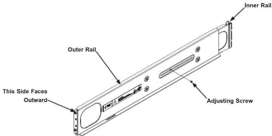
text_image
Inner Rail Outer Rail This Side Faces Outward Adjusting ScrewFigure 2-1. Identifying the Rail Sections

Slide rail mounted equipment is not to be used as a shelf or a work space.

Warning: do not pick up the server with the front handles. They are designed to pull the system from a rack only.
Installing the Rails on a Rack
Installing the Rails
- Adjust the length of both rails as described on the previous page.
- Align the front section of the outer rail with the slots on the front post of the rack. Secure the front of the outer rail to the rack with two screws.
- Pull out the rear section of the outer rail, adjusting the length until it fits within the posts of the rack.
- Align the rear section of the rail with the slots on the rear post of the rack. Secure the rear of the outer rail to the rear of the rack with two screws.
- Repeat steps 1-4 for the remaining rail.
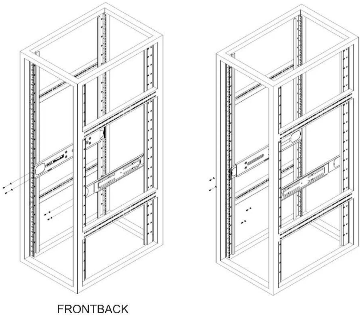
Figure 2-2. Attaching the Rails to a Rack
Chassis Installation
Installing the Chassis into a Rack
- Confirm that the rails are correctly installed on the rack.
- Align the bottom of the chassis with the bottom of the rails.
- Insert the chassis into the F619P2-FT+ rails, keeping the pressure even on both sides, pushing the chassis into the rack until it clicks into the locked position.
- Secure the chassis handles to the front of the rack.
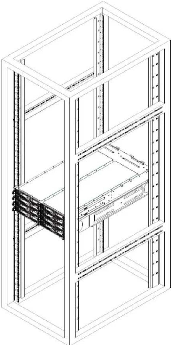
natural_image
Isometric line drawing of a server rack cabinet with multiple racks and ventilation grilles (no text or labels)Figure 2-3. Installing into a Rack
Note: The figure above is for illustration purposes only and does not represent exactly the same server in this manual. Always install servers to the bottom of the rack first.
Chapter 3
Maintenance and Component Installation
This chapter provides instructions on installing and replacing main system components. To prevent compatibility issues, only use components that match the specifications and/or part numbers given.
Installation or replacement of most components require that power first be removed from the system. Please follow the procedures given in each section.
3.1 Removing Power
Use the following procedure to ensure that power has been removed from the system. This step is necessary when removing or installing non hot-swap components or when replacing a non-redundant power supply.
Removing the Power Cord
- Use the operating system to power down the system, following the on-screen prompts.
- After the system has completely shut-down, carefully grasp the head of the power cord and gently pull it out of the back of the power supply.
- If your system has dual redundant power supplies, remove the cords from both power supplies.
- Disconnect the cord from the power strip or wall outlet.
3.2 Chassis Components
The chassis includes power supplies, fans and eight nodes. Each node is a separate system containing a drawer with a serverboard and other components. Each node may be removed from the chassis separately.
Installing and Removing the Node Drawers
The F418IF3 chassis contains eight individual motherboards in separate node drawers (Figure 3-1). Each motherboard node controls a set of two internal fixed hard drives. Note that if a motherboard node drawer is pulled out of the chassis, the hard drives associated with that node will power down as well.

text_image
Node Node 3 Node 2 Node 1 Node 8 Node 7 Node 6 Node 5Figure 3-1. Installing and Removing the Node Drawers
Removing Nodes from the Chassis
Each of the eight individual nodes may be removed from the chassis separately. Note that when a node is removed from the chassis, the hard drives located in the node will shut-down.
Removing a Node
- Grasp the node by the handles on both sides of the front of the node.
- Press down on the left handle to disengage the latch.
- While holding down the left handle, carefully pull the node forward and out of the chassis.
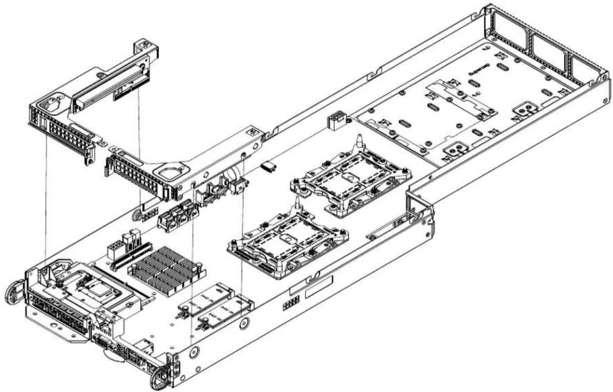
Removing the Cover from the Node
Removing the Node Cover
- Remove the node from the chassis as described above.
- Push the top cover toward the rear side of the node.
- Lift the cover up and off the node.
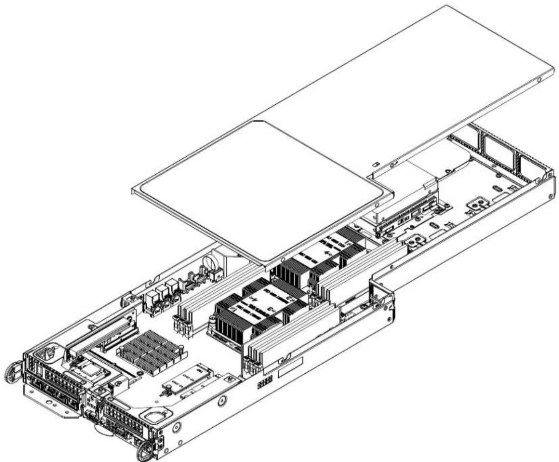
natural_image
Technical line drawing of an internal server rack with visible internal components and ventilation slots (no text or labels)Figure 3-2. Removing the Node Cover
Node Configurations
Overview of the Node
Node configuration for a typical node is shown below in Figure 3-3.

text_image
Front of the Node Rear of the NodeFigure 3-3. Front and Rear of the F418IF3-R2K20BP Node
F418IF3-R2K20BP Node Layout
The specifications for the F418IF3-R2K20BP nodes are shown in the table below.
| F418IF3-R2K20BP Node Layout Specifications | |
| Front of Node Rear of Node | |
| Two low-profile PCI-E expansion cards Up to four fixed internal HDD's | |
Nodes and Associated Hard Drives
The F418IF3 chassis contains up to eight individual motherboards in separate 1U nodes. Each node has two 2.5" drives, with an additional optional two 2.5" drives. Zero nodes have eight drives. Note that if a node is pulled out of the chassis, the hard drives associated with that node will power down as well. Refer to the charts below and on the following pages for your specific chassis configuration
Installing and Removing 2.5" Hard Drives
Removing 2.5" Fixed Hard Drives from the Node
- Remove the node from the chassis and remove the cover from the node as described previously in this section.
- Remove the screw securing the hard drive tray to the floor of the chassis.
- Lift the hard drive and tray up and out of the chassis.

natural_image
Technical line drawing of an internal server rack with multiple drive bays and ventilation slots (no text or labels)Figure 3-4. Removing a 2.5" Fixed Hard Drive in a Node
- Remove the screws securing the hard drive to the tray and set them aside for later use.

text_image
Technical diagram of a device stack with numbered components and an upward arrow indicating motion or assembly.Figure 3-5. Installing a Hard Drive in the Drive Carrier
- Lift the hard drive up and out of the tray.
- Install a replacement drive into the hard drive tray and secure it to the tray with the screws previously set aside.

natural_image
Isometric technical diagram of a server rack with internal components and a numbered component (no text or symbols)Figure 3-6. Replacing a 2.5" Fixed Hard Drive from the Node
- Secure the hard drive tray to the floor of the node with the screw previously set aside.
- Replace the node cover and return the node to its bay in the chassis.
Drive Carrier Indicators
Each drive carrier has two LED indicators: an activity indicator and a status indicator. For RAID configurations using a controller, the meaning of the status indicator is described in the table below. For OS RAID or non-RAID configurations, some LED indications are not supported, such as hot spare. For VROC configurations, refer to the VROC appendix in this manual.
| Drive Carrier LED Indicators | |||
| Color Blinking Pattern Behavior | for Device | ||
| Activity LED | Blue Solid On SAS/NVMe drive installed | ||
| Blue Blinking I/O activity | |||
| Status LED | Red Solid On Failure of drive with RSTe support | ||
| Red Blinking at 1 Hz Rebuilding drive with RSTe support | |||
| Red Blinking with two blinks and one stop at 1 Hz | Hot spare for drive with RSTe support (not supported in VMD mode) | ||
| Red On for five seconds, then off | Power on for drive with RSTe support | ||
| Red Blinking at 4 Hz Identify drive with RSTe support | |||
| Green Solid On Safe to remove NVMe device (not supported in VMD mode) | |||
| Amber Blinking at 1 Hz Attention state—do not remove NVMe device (not supported in VMD mode) | |||
Note: Enterprise level hard disk drives are recommended for use in Supermicro chassis and servers. For information on recommended HDDs, visit the Supermicro website at https://www.supermicro.com/products/nfo/Ultra.cfm.
Hot-Swap for NVMe Drives
An NVMe drive can be inserted and replaced using IPMI.
Note: If you are using VROC, see the VROC appendix in this manual instead.
Ejecting a Drive
- IPMI > Server Health > NVMe SSD
- Select Device, Group and Slot, and click Eject. After ejecting, the drive Status LED indicator turns green.
- Remove the drive.
Note that Device and Group are categorized by the CPLD design architecture.
Slot is the slot number on which the NVMe drives are mounted.
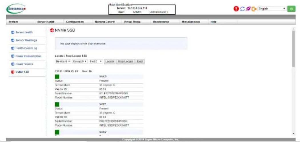
text_image
Host Identification Server: 172.051.049.118 User: ADMIN (Administrator) System Server Health Configuration Remote Control Virtual Media Maintenance Miscellaneous Help Server Health Sensor Readings Health Event Log Power Consumption Power Source NVMe SSD NVMe SSD This page displays NVMe SSD information Locate / Stop Locate $SD Device: 0 Group: 0 Slot: 0 Locate Stop Locate Eject CPLD / RPM ID: FF Rev: 10 Status: Present Temperature: 35 degrees C Vendor ID: 80.86 Serial Number: RTLPT2708E7MAP0IGN Model Number INTEL SSDPE2X0X40T7 Slot:1 Status: Present Temperature: 33 degrees C Vendor ID: 80.86 Serial Number: PHLFT20500S8HP0IGN Model Number INTEL SSDPE2X0X40T7 Slot:2 Copyright © 2014 Super Micro Computer, Inc.Figure 3-7. IPMI Screenshot
Replacing the Drive
- Insert the replacement drive.
- IPMI > Server Health > NVMe SSD
- Select Device, Group and slot and click Insert. The drive Status LED indicator flashes red, then turns off. The Activity LED turns blue.
Checking the Temperature of an NVMe Drive
There are two ways to check using IPMI.
Checking a Drive
- IPMI > Server Health > NVMe SSD – Shows the temperatures of all NVMe drives, as in Figure 3-4.
- IPMI > Server Health > Sensor Reading > NVME_SSD – Shows the single highest temperature among all the NVMe drives.
Installing Expansion Cards
Each of the eight nodes in the chassis has space for two low-profile expansion cards mounted in the front of the node. The following instructions are for chassis nodes in which the expansion cards are mounted in the front of the node.

text_image
PCI-E Slot Clip PCI-E Slot ShieldFigure 3-9. PCI-E Slot Configuration
Assembling the PCI-E Slot Bracket Assembly
Each node supports two expansion cards in front of the node. Each expansion card must be plugged into a riser card, which in turn plugs into the motherboard.
Assembling the PCI-E Slot Bracket Assembly
- Remove the node from the chassis and remove the cover from the node as described previously in this section.
- Open the PCI-E slot clip and remove the PCI-E slot shield. (See the illustration on the previous page)
- Remove the tool-less PCI-E slot bracket.
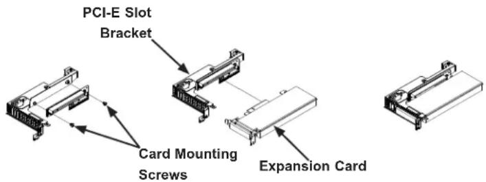
text_image
PCI-E Slot Bracket Card Mounting Screws Expansion CardFigure 3-10. Assembling the PCI-E Slot Bracket and Riser Card
-
Lift the PCI-E slot bracket out of the node.
-
Insert the riser card into the appropriate slot on the motherboard.
- Simultaneously insert the expansion card into the riser card, while sliding the expansion card bracket into the open PCI-E slot.
natural_image
Technical line drawing of an internal server rack with multiple modules and connectors (no text or labels)Figure 3-11. Installing the Expansion Card and Bracket into the Node
Installing Air Shrouds
Air Shrouds
Air shrouds concentrate airflow to maximize fan efficiency. The F418IF3 chassis require an air shroud in each node.
Installing an Air Shroud
- Remove the node from the chassis and remove the cover from the node as described previously in this section.
- Make sure that the motherboard and all components are properly installed in each node.
- Place the two (2) air shrouds over the motherboard, as illustrated below.
- Repeat the procedure for the remaining nodes.
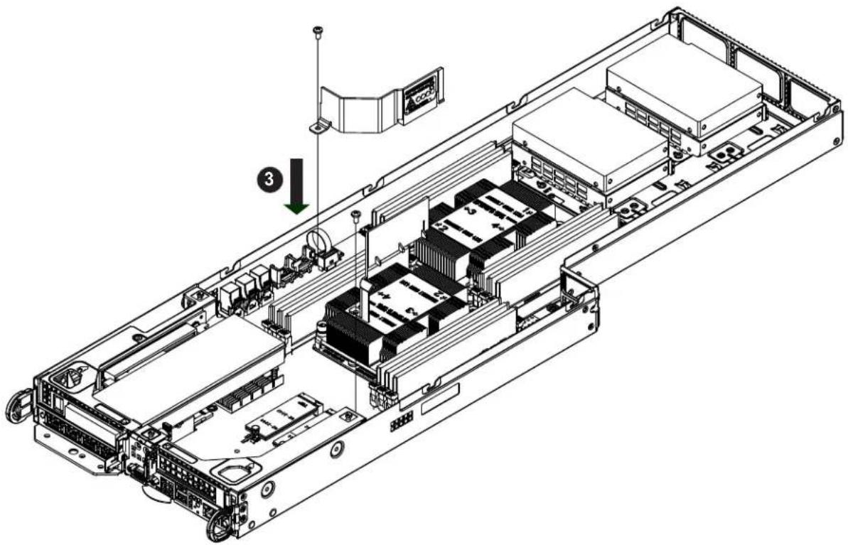
text_image
Technical diagram of an electronic device chassis with labeled components and a numbered indicator (3)Figure 3-12. Installing the Air Shroud
Removing and Installing System Fans
Removing and Installing External System Fans
The chassis has eight fans in the rear of the system. Fans that fail can be replaced by simply removing them from the rear without powering down the system.
Removing a Rear Exhaust Fan
- Determine which fan has failed.
- Press the release tabs on the fan and pull it away from rear of the system.
Installing a Rear Exhaust Fan
- Press the release tabs on the fan and insert it into the open fan bay.
- Push the fan into the bay until it clicks into the locked position.

natural_image
Technical line drawing of a server rack unit with multiple drive bays and mounting hardware (no text or labels)Figure 3-13. Installing the External Fan
Replacing the Power Supplies
The F418IF3 chassis includes four redundant 2000 or 2200 Watt power supplies. These power supplies are auto-switching capable. This enables the power supplies to automatically sense and operate at a 100v to 240v input voltage. An amber light will be illuminated on the power supply when the power is off. An illuminated green light indicates that the power supply is operating.
Power Supply Replacement
The F418IF3 chassis utilizes redundant power supplies. In the unlikely event that the power supply unit needs to be replaced, a power supply can be removed, without powering down the system. Replacement units can be ordered directly from Supermicro (See the contact information in the Preface of this manual).
Changing the Power Supply
- Disconnect the AC power cord on the back of the failed power supply.
- Press the release tab on the back of the power supply and pull the power supply out using the handle provided.
- Push the replacement power supply module into the power bay until it clicks into the locked position.
- Plug the AC power cord back into the power supply module and power it up.
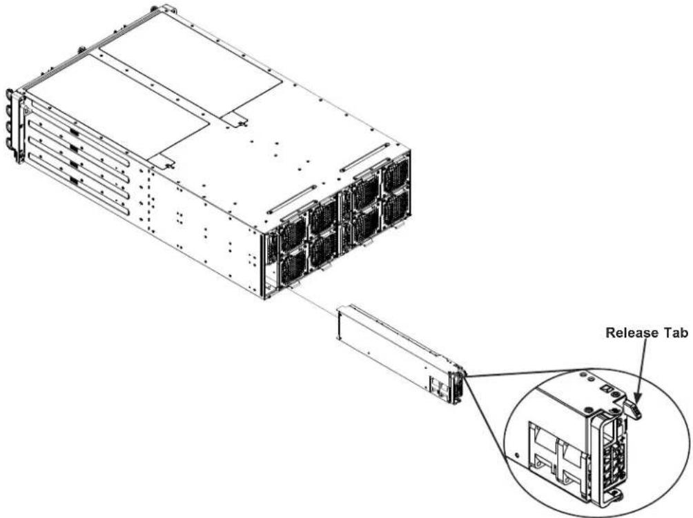
text_image
Release TabFigure 3-14. Changing the F418IF3 Chassis Power Supplies
3.3 Motherboard Components
Processor and Heatsink Installation
Warning: When handling the processor package, avoid placing direct pressure on the label area of the fan. Also, improper CPU installation or socket misalignment can cause serious damage to the CPU or the motherboard that will require RMA repairs. Please read and follow all instructions thoroughly before installing your CPU and heatsink.
Notes:
- Always connect the power cord last, and always remove it before adding, removing or changing any hardware components. Make sure that you install the processor into the CPU socket before you install the CPU heatsink.
- If you buy a CPU separately, make sure that you use an Intel-certified multi-directional heatsink only.
- Make sure to install the motherboard into the chassis before you install the CPU heatsink.
- When receiving a motherboard without a processor pre-installed, make sure that the plastic CPU socket cap is in place and none of the socket pins are bent; otherwise, contact your retailer immediately.
• Refer to the Supermicro website for updates on CPU support.
The Processor
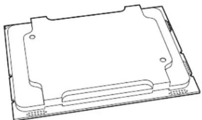
natural_image
Technical line drawing of a rectangular electronic component or tray (no text or symbols)(The 81xx/61xx/51xx/41xx/31xx and 82xx/62xx/52xx/42xx/32xx processor)
Note: All graphics, drawings and pictures shown in this manual are for illustration only. The components that came with your machine may or may not look exactly the same as those shown in this manual.
Overview of the Processor Socket Assembly
The processor socket assembly contains 1) the 81xx/61xx/51xx/41xx/31xx and 82xx/62xx/52xx/42xx/32xx processor 2) CPU/heatsink carrier, 3) dust cover, and 4) CPU socket.
- The 81xx/61xx/51xx/41xx/31xx and 82xx/62xx/52xx/42xx/32xx processor Processor
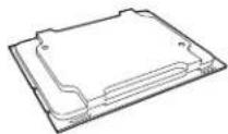
- CPU/Heatsink Carrier
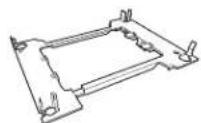
- Dust Cover

- CPU Socket
natural_image
Technical line drawing of a mechanical component with mounting holes and internal grating (no text or symbols)
text_image
CPU Socket AssemblyNote: Be sure to cover the CPU socket with the dust cover when the CPU is not installed.
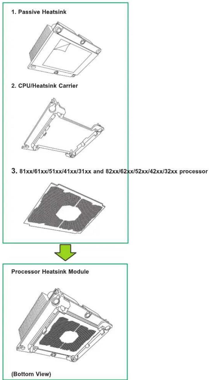
Overview of the Processor Heatsink Module
The processor heatsink module (PHM) contains 1) a passive heatsink, 2) a CPU/heatsink carrier, and 3) The 81xx/61xx/51xx/41xx/31xx and 82xx/62xx/52xx/42xx/32xx processor.
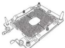
Preparing the CPU Socket for Installation
This motherboard comes with the CPU socket pre-assembled in the factory. The CPU socket contains 1) a dust cover, 2) a socket bracket, 3) the CPU (LGA3647) socket, and 4) a back plate. These components are pre-installed on the motherboard before shipping.
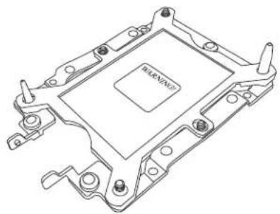
natural_image
Technical line drawing of a computer processor casing (no text or symbols)Processor Socket Assembly
Removing the Dust Cover from the CPU Socket
Remove the dust cover from the CPU socket, exposing the LGA3647 socket and socket pins as shown on the illustration below.
Note: Do not touch the socket pins to avoid damaging them, causing the CPU to malfunction.

text_image
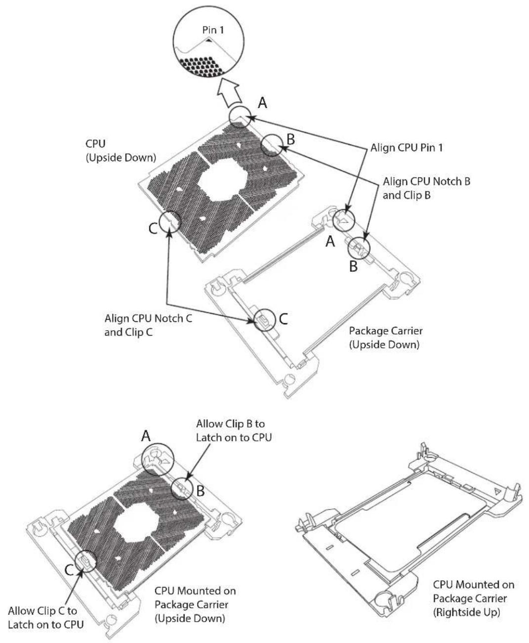
Socket Cover Socket Pins LGA3647 SocketAttaching the Processor to the CPU/Heatsink Carrier
To properly install the CPU onto the CPU/heatsink carrier, please follow the steps below. Installing the CPU onto the CPU/heatsink
- Locate Pin 1 (Notch A), Notch B, and Notch C on the CPU and locate Pin 1 (Notch A), Notch B, and Notch C on the CPU/heatsink carrier.
- Align Pin 1 (Notch A), Notch B, and Notch C on the CPU with the corresponding notches on the carrier. Once they are aligned, carefully insert the CPU into the carrier until you hear a click. Once the CPU is properly mounted onto the carrier, the CPU/ carrier assembly is made.
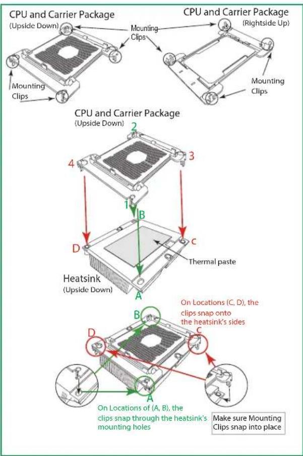
Attaching the CPU/Carrier Assembly to the Passive Heatsink to Form the Processor Heatsink Module (PHM)
After you have made a CPU/carrier assembly, please follow the steps below to mount the assembly onto the heatsink to create the Processor Heatsink Module (PHM).
-
Place the heatsink upside down with the thermal grease facing up. Locate two larger mounting holes (A, B) at the diagonal corners of the heatsink, and two smaller mounting holes (C, D) on the heatsink.
-
Hold the CPU/carrier at the center edge, and turn it upside down with the CPU pins facing up. Locate the two larger holes (1, 2) at the diagonal corners of the carrier and the smaller holes of the same size (3, 4) on the carrier. Please note the mounting clips located next to every mounting hole on the carrier.
-
Align the larger holes (1, 2) on the carrier against the larger mounting holes (A, B) on the heatsink and smaller holes (3, 4) on the carrier against the smaller mounting holes (C, D) on the heatsink. Insert the mounting clips next to the larger hole on the carrier into the larger mounting hole on the heatsink ( 1 A , 2 B ) and snap the mounting clips next to the smaller holes on the carrier onto the edges of the heatsink next to the smaller holes ( 3 C , 4 D ) making sure that the mounting clips snap into place, and that the CPU/carrier assembly is properly mounted onto the heatsink. By mounting the CPU/carrier assembly to the heatsink, the Processor Heatsink Module (PHM) is assembled.
flowchart
graph TD
    A["CPU and Carrier Package (Upside Down)"] --> B["Mounting Clips"]
    B --> C["Heatsink (Upside Down)"]
    C --> D["Thermal paste"]
    D --> E["On Locations (A, B), the clips snap through the heatsink's mounting holes"]
    E --> F["Make sure Mounting Clips snap into place"]
    G["CPU and Carrier Package (Rightside Up)"] --> H["Mounting Clips"]
    H --> I["Heatsink (Upside Down)"]
    I --> J["Thermal paste"]
    J --> K["On Locations (C, D), the clips snap onto the heatsink's sides"]
    K --> L["Make sure Mounting Clips snap into place"]
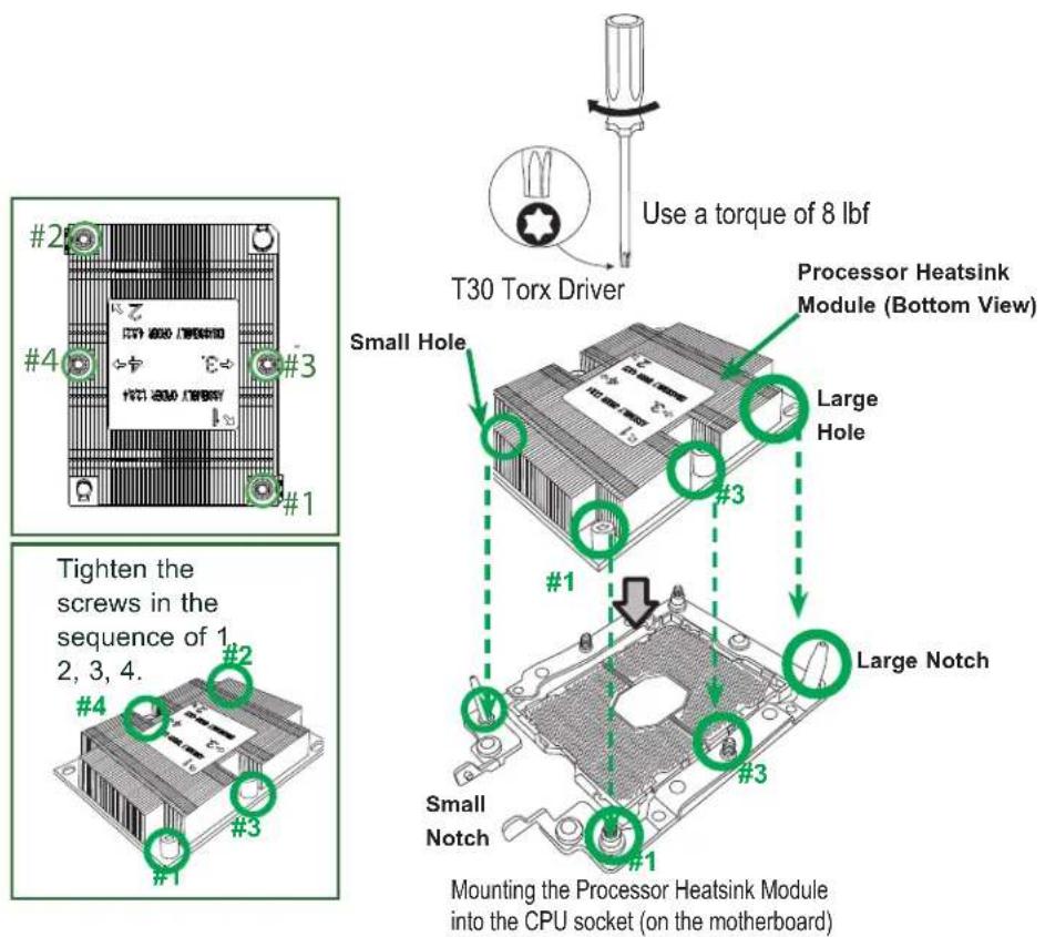
Installing the Processor Heatsink Module (PHM)
- Once you have assembled the processor heatsink module (PHM) by following the instructions listed on the previous page, align the processor heatsink module with the CPU socket on the motherboard.
- Align the large hole on the heatsink against the large notch on the CPU socket, the small hole on the heatsink against the small notch on the socket. Carefully insert the PHM into the socket, making sure that the large and small notches fit through the corresponding mounting holes on the socket. The PHM will only fit one way. If it does not fit correctly, remove it and try again.
- Using a T30-size star driver bit, tighten eight screws into the mounting holes on the socket to securely install the PHM into the motherboard, starting with the mounting hole marked #1 (in the sequence of 1, 2, 3, and 4).
Note: Do not use excessive force when tightening the screws to avoid damaging the CPU and the socket.
text_image
#2 #4 #3 #1 Tighten the screws in the sequence of 1, 2, 3, 4. #2 #4 #3 #1 Use a torque of 8 lbf T30 Torx Driver Small Hole Processor Heatsink Module (Bottom View) Large Hole #3 #1 Large Notch Small Notch #3 #1 Mounting the Processor Heatsink Module into the CPU socket (on the motherboard)Removing the Processor Heatsink Module (PHM)
Before starting to remove the processor heatsink module (PHM), unplug power cord from the power outlet.
- Using a T30-size star driver, turn the screws on the PHM counterclockwise to loosen it from the socket, starting with screw marked #4 (in the sequence of 4, 3, 2, 1).
- After all eight screws are removed, wiggle the PHM gently and pull up to remove it from the socket.
Note: To properly remove the processor heatsink module, be sure to loosen and remove the screws on the PHM in the sequence of 4, 3, 2, 1 as shown below.

text_image
#2 #4 #3 #1 #2 #4 #3 #1 Removing the screws in the sequence of 4, 3, 2, 1. #2 #4 #3 #1 Starting from here → #4 #2 #3Memory Support and Installation
Note: Check the Supermicro website for recommended memory modules.
Important: Exercise extreme care when installing or removing DIMM modules to prevent any damage.
ESD Precautions
Electrostatic Discharge (ESD) can damage electronic components including memory modules. To avoid damaging your DIMM modules, it is important to handle it very carefully. The following measures are generally sufficient to protect your equipment from ESD.
Precautions
- Use a grounded wrist strap designed to prevent static discharge.
- Handle the memory module by its edges only.
- Put the memory modules into the antistatic bags when not in use.
- Check the Supermicro website for recommended memory modules
Introduction to Intel® Optane DC Persistent Memory
Intel® 82xx/62xx/52xx/42xx supports new DCPMM (Optane™ DC Persistent Memory Modules) technology. DCPMM offers data persistence with higher capacity at lower latencies than the existing memory modules and provides hyper-speed storage capability for high performance computing platforms with flexible configuration options.
Memory Support
Integrated memory controller embedded in the processor supports up to 1.5 TB of 3DS Load Reduced DIMM (3DS LRDIMM), Load Reduced DIMM (LRDIMM), 3DS Registered DIMM (3DS RDIMM), Registered DIMM (RDIMM), and NVDIMM DDR4 (288-pin) ECC memory of 2933/2666/2400/2133 MHz in 12 slots
Note: 2933 MHz memory is supported by the 82xx/62xx series processors only.
| DDR4 Memory Support for 81xx/61xx/51xx/41xx/31xx Processors | ||||||
| Type | Ranks Per DIMM and Data Width | DIMM Capacity (GB) | Speed (MT/s) | |||
| One Slot per Channel | Two Slots per Channel | |||||
| DRAM Density | One DIMM per Channel | One DIMM per Channel | Two DIMMs per Channel | |||
| 4 Gb 8 Gb 1.2 Volts 1.2 Volts 1.2 Volts | ||||||
| RDIMM | SRx4 4 GB | 8 GB | 2666 2666 2666 | |||
| SRx8 8 GB | 16 GB | |||||
| DRx8 8 GB | 16 GB | |||||
| DRx4 16 GB | 32 GB | |||||
| RDIMM 3Ds | QRX4 N/A | 2H-64GB | ||||
| 8RX4 N/A | 4H-128GB | |||||
| LRDIMM QRx4 | 32 GB 64 GB | |||||
| LRDIMM 3Ds | QRx4 N/A | 2H-64GB | ||||
| 8Rx4 N/A | 4H-128 GB | |||||
| DDR4 Memory Support for 82xx/62xx/52xx/42xx/32xx Processors | |||||||
| Type | Ranks Per DIMM and Data Width | DIMM Capacity (GB) | Speed (MT/s) | ||||
| One Slot per Channel | Two Slots per Channel | ||||||
| DRAM Density | One DIMM per Channel | One DIMM per Channel | Two DIMMs per Channel | ||||
| 4 Gb 8 | Gb 16 Gb 1 | 2 Volts 1.2 | Volts 1.2 Volts | ||||
| RDIMM | SRx4 | 4 GB | 8 GB | 16 GB | 2933 | 2933 | 2933 |
| SRx8 | 8 GB | 16 GB | 32 GB | ||||
| DRx8 | 8 GB | 16 GB | 32 GB | ||||
| DRx4 | 16 GB | 32 GB | 64 GB | ||||
| RDIMM 3Ds | QRX4 | N/A 2H-64GB | 2H-128GB | ||||
| 8RX4 | N/A 4H-128GB | 4H-256GB | |||||
| LRDIMM | QRx4 | 32 GB | 64 GB | 128 GB | |||
| LRDIMM 3Ds | QRx4 | N/A 2H-64GB | 2H-64GB | ||||
| 8Rx4 | N/A 4H-128 GB | 4H-256 GB | |||||
Check the Supermicro website for possible updates to memory support.
Memory Installation Sequence
Memory modules for the X11 UP/DP/MP motherboards are populated using the "Fill First" method. The blue memory slot of each channel is considered the "first DIMM module" of the channel, and the black slot, the second module of the channel. When installing memory modules, be sure to populate the blue memory slots first and then populate the black slots. To maximize memory capacity and performance, please populate all DIMM slots on the motherboard, including all blue slots and black slots.
General Memory Population Requirements
- Be sure to use the memory modules of the same type and speed on the motherboard. Mixing of memory modules of different types and speeds is not allowed.
- Using unbalanced memory topology such as populating two DIMMs in one channel while populating one DIMM in another channel on the same motherboard will result in reduced memory performance.
- Populating memory slots with a pair of DIMM modules of the same type and size will result in interleaved memory, which will improve memory performance.
Note: Unbalanced memory configuration decreases memory performance and is not recommended for Supermicro motherboards.
Memory Population Table for X11DP Motherboards (w/12 Slots) based on the 81xx/61xx/51xx/41xx/31xx and 82xx/62xx/52xx/42xx/32xx Platforms
| Memory Population Tables for X11DP Motherboards w/12 DIMM Slots | |
| CPUs/DIMMs Memory Population Sequence | |
| 1 CPU & 1 DIMM CPU1: P1-DIMMA1 | |
| 1 CPU & 2 DIMMs CPU1: P1-DIMMA1/P1-DIMMD1 | |
| 1 CPU & 3 DIMMs CPU1: P1-DIMMC1/P1-DIMMB1/P1-DIMMA1 | |
| 1 CPU & 4 DIMMs CPU1: P1-DIMMB1/P1-DIMMA1/P1-DIMMD1/P1-DIMME1 | |
| 1 CPU & 5 DIMMs* CPU1: P1-DIMMC1/P1-DIMMB1/P1-DIMMA1/P1-DIMMD1/P1-DIMME1 | |
| 1 CPU & 6 DIMM CPU1: P1-DIMMC1/P1-DIMMB1/P1-DIMMA1/P1-DIMMD1/P1-DIMME1/P1-DIMMF1 | |
| 2 CPUs & 2 DIMMs | CPU1: P1-DIMMA1CPU2: P2-DIMMA1 |
| 2 CPUs & 4 DIMMs | CPU1: P1-DIMMA1/P1-DIMMD1CPU2: P2-DIMMA1/P2-DIMMD1 |
| 2 CPUs & 6 DIMMs | CPU1: P1-DIMMC1/P1-DIMMB1/P1-DIMMA1CPU2: P2-DIMMC1/P2-DIMMB1/P2-DIMMA1 |
| 2 CPUs & 8 DIMMs | CPU1: P1-DIMMB1/P1-DIMMA1/P1-DIMMD1/P1-DIMME1CPU2: P2-DIMMB1/P2-DIMMA1/P2-DIMMD1/P2-DIMME1 |
| 2 CPUs & 10 DIMMs | CPU1: P1-DIMMC1/P1-DIMMB1/P1-DIMMA1/P1-DIMMD1/P1-DIMME1/P1-DIMMF1CPU2: P2-DIMMB1/P2-DIMMA1/P2-DIMMD1/P2-DIMME1 |
| 2 CPUs & 12 DIMMs | CPU1: P1-DIMMC1/P1-DIMMB1/P1-DIMMA1/P1-DIMMD1/P1-DIMME1/P1-DIMMF1CPU2: P2-DIMMC1/P2-DIMMB1/P2-DIMMA1/P2-DIMMD1/P2-DIMME1/P2-DIMMF1 |
*Unbalanced, not recommended.
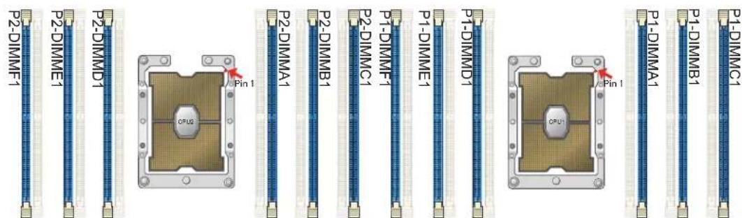
text_image
P2-DIMMF1 P2-DIMME1 P2-DIMMD1 Pin 1 OPUS P2-DIMMA1 P2-DIMMB1 P1-DIMMF1 P2-DIMMC1 P1-DIMME1 P1-DIMMD1 Pin 1 OPU1 P1-DIMMA1 P1-DIMMB1 P1-DIMMC1Note: The drawing above shows DIMM module population for each CPU installed on the motherboard. Please install your processors starting with CPU Socket 1.
DCPMM Table for the X11DP Motherboards (w/12 Slots) based on the 82xx/62xx/52xx/42xx Platform
| Symmetric Population within 1 CPU Socket | |||||||
| Modes | P1-DIMMF1 | P1-DIMME1 | P1-DIMMD1 | P1-DIMMA1 | P1-DIMMB1 | P1-DIMMC1 | Channel Config. |
| AD DCPMM DRAM1 DRAM1 DRAM1 DRAM1 DCPMM 1-1-1 | |||||||
| MM DCPMM DRAM1 DRAM1 DRAM1 DRAM1 DCPMM 1-1-1 | |||||||
| AD + MMDCPMM DRAM3 DRAM3 DRAM3 DRAM3 DCPMM 1-1-1 | |||||||
| Legend (for the table above) | |||||
| DDR4 Type Capacity | |||||
| DRAM1 | DIMM 3DS | RDIMM LRDIMM | MM | 3DSLRDIMM | Any Capacity |
| DRAM2 | RDIMM | - | - | Refer to Validation Matrix (DDR4 DIMMs validated with DCPMM) below. | |
| DRAM3 | RDIMM | 3DS RDIMM | LRDIMM | - | |
Note: DDR4 single rank x8 is not available for DCPMM Memory Mode or App-Direct Mode.
| Legend (for the first table above) | |
| Capacity | |
| DCPMM | Any Capacity (Uniformly for all channels for a given configuration) |
•* 2nd socket has no DCPMM DIMM
• For MM, general NM/FM ratio is between 1:4 and 1:16. Excessive capacity for FM can be used for AD. (NM = Near Memory; FM = Far Memory)
- For each individual population, rearrangements between channels are allowed as long as the resulting population is compliant with the PDG rules for the 82xx/62xx/52xx/42xx platform.
•For each individual population, please use the same DDR4 DIMM in all slots.
- For each individual population, sockets are normally symmetric with exceptions for 1 DCPMM per socket and 1 DCPMM per node case. Currently, DCPMM modules operate at 2666 MHz.
• No mixing of DCPMM and NVMDIMMs within the same platform is allowed.
•This DCPMM population guide targets a balanced DCPMM-to-DRAM-cache ratio in MM and MM + AD modes.
| Validation Matrix (DDR4 DIMMs Validated w/DCPMM) | |||
| DIMM Type | Ranks Per DIMM & Data Width (Stack) | DIMM Capacity (GB) | |
| DRAM Density | |||
| 4Gb | 8Gb | ||
| RDIMM | 1Rx4 | 8GB | 16GB |
| 2Rx8 | 8GB | 16GB | |
| 2Rx4 | 16GB | 32GB | |
| LRDIMM | 4Rx4 | N/A | 64GB |
| LRDIMM 3DS | 8Rx4 (4H) | N/A | 128GB |
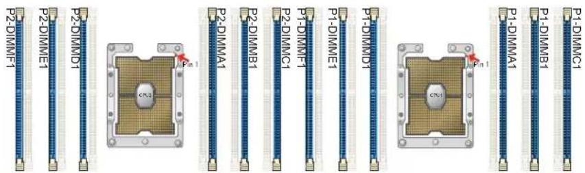
text_image
P2-DIMM1 P2-DIMM1 P2-DIMMD1 P2-DIMMA1 P2-DIMMB1 P1-DIMM1 P1-DIMM1 P1-DIMME1 P1-DIMMD1 P1-DIMMA1 P1-DIMMB1 P1-DIMMC1DIMM Installation
- Follow the instructions given in the memory population guidelines listed in the previous sections to install memory modules on your motherboard. For the system to work properly, please use memory modules of the same type and speed on the motherboard. (See the Note below.)
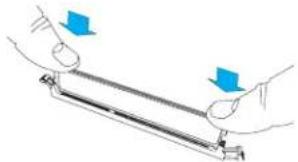
- Push the release tabs outwards on both ends of the DIMM slot to unlock it.
- Align the key of the DIMM module with the receptive point on the memory slot.
- Align the notches on both ends of the module against the receptive points on the ends of the slot.
- Use two thumbs together to press the DIMM module straight down into the slot until the module snaps into place.
- Press the release tabs to the lock positions to secure the DIMM module into the slot.

natural_image
Floor plan diagram of a computer room with green structural elements and no visible text or labels
text_image
Notches
text_image
Release TabsInsert the DIMM module into the memory slot.
natural_image
Illustration of two hands holding a metal rod with blue arrows indicating direction (no text or symbols)DIMM Module Removal
Press the release tabs on both ends of the DIMM socket to release the DIMM module from the socket as shown in the drawing on the right.

Warning! 1. T to avoid damage to the DIMM module or the DIMM socket, do not use excessive force when pressing the release tabs on the ends of the DIMM socket. 2. Handle DIMM modules with care. Carefully follow all the instructions given in Section 1 of this user guide to avoid ESD-related damage to your components or system. 3. All graphics, including the layout drawing above, are for reference only. Your system components may or may not look the same as shown in this user guide.
Motherboard Battery
The motherboard uses non-volatile memory to retain system information when system power is removed. This memory is powered by a lithium battery residing on the motherboard.
Replacing the Battery
Begin by removing power from the system as described in section 3.1.
- Push aside the small clamp that covers the edge of the battery. When the battery is released, lift it out of the holder.
- To insert a new battery, slide one edge under the lip of the holder with the positive (+) side facing up. Then push the other side down until the clamp snaps over it.
Note: Handle used batteries carefully. Do not damage the battery in any way; a damaged battery may release hazardous materials into the environment. Do not discard a used battery in the garbage or a public landfill. Please comply with the regulations set up by your local hazardous waste management agency to dispose of your used battery properly.

text_image
LITHIUM BATTERY BATTERY HOLDERFigure 3-15. Installing the Onboard Battery
Warning: There is a danger of explosion if the onboard battery is installed upside down (which reverses its polarities). This battery must be replaced only with the same or an equivalent type recommended by the manufacturer (CR2032).
Chapter 4
Motherboard Connections
This section describes the connections on the motherboard and provides pinout definitions. Note that depending on how the system is configured, not all connections are required. The LEDs on the motherboard are also described here. A severboard layout indicating component locations may be found in Chapter 1.
Please review the Safety Precautions in Chapter 3 before installing or removing components.
4.1 Power Connections
8-Pin Power Connectors for Power Adaptor Cards
Two 8-pin 12V power connectors, located at JPW1/JPW2, are used to provide main power to your system via power adaptor cards. Connect appropriate power cables to JPW1/JPW2 and the power adaptor cards to supply power to your system. See the table below for pin definitions.
| 12V 8-pin Power Pin Definitions |
| Pin# Definition |
| 1 - 4 Ground |
| 5 - 8 +12V |
Auxiliary Power Connector
The Auxiliary power connector is located at JPW3. Connect an appropriate power cable to JPW3 and a power adaptor card to provide power to your devices. See the table below for pin definitions.
| 9-pin PowerPin Definitions | |||
| Pin# Definitions Pin# Definition | |||
| 1 P5V | STBY 2 P5V_STBY | ||
| 3 SMB | CLK_P12V_HS 4 SCL_PMB_R | ||
| 5 SMB | DAT_P12V_HS 6 SDA_PMB_R | ||
| 7 PS_ON_N_PWR 8 PS_PMBUS | ALERT_N | ||
| 10 Ground | |||
8-Pin HDD Power Connectors
Two 8-pin HDD power connectors, located at HDD_PWR1/2, provide power to HDD devices. Connect appropriate power cables to use HDD power connectors. See the table below for pin definitions.
| 8-pin Power HDD_PWR1/2 Pin Definitions | |||
| Pin# Definitions Pin# Definition | |||
| 1 Ground | 2 P12V | ||
| 2 Ground | 4 P12V | ||
| 3 Ground | 6 P5V | ||
| 4 Ground | 10 P5V | ||
4-Pin HDD Power Connectors
In addition to 8-pin HDD power connectors, there are two 4-pin HDD power connectors (HDD_PWR3/4) on the motherboard. Connect appropriate power cables to these connectors to supply power to your HDD devices. See the table below for pin definitions.
| 4-pin Power HDD_PWR3/4Pin Definitions | |||
| Pin# Definitions Pin# Definition | |||
| 1 NA 3 P12V | |||
| 2 Ground 4 P5V | |||
4.2 Headers and Connectors
Onboard Fan Headers
Four 4-pin fan headers (FAN1-FAN4) are located on the motherboard to provide CPU/system cooling. These fan headers support both 3-pin fans and 4-pin fans; however, onboard fan speed control is available only when all 4-pin fans are used in your system. Fan speed control is supported by a thermal management setting in the BMC (Baseboard Management Controller). See the table below for pin definitions.
| Fan HeaderPin Definitions | |
| Pin# | Definition |
| 1 | Ground (Black) |
| 2 | +12V (Red) |
| 3 | Tachometer |
| 4 | PWM Control |
NVMe Connectors
Four NVMe connectors (NVMe0/NVMe1/NVMe2/NVMe3), supported by CPU2, can be used for PCI-E high-speed storage devices.
RAID Key Header
A RAID Key header is located at JRK1 on the motherboard. The RAID key is used to support NVMe SDD.
| Intel RAID KeyPin Definitions | |
| Pin# | Definition |
| 1 | Ground |
| 2 | 3.3V Standby |
| 3 | Ground |
| 4 | PCH RAID Key |
4-pin BMC External I²C Header
A System Management Bus header for IPMI 2.0 is located at JIPMB1. Connect a cable to this header to use the IPMB I²C connection on your system. See the table below for pin definitions.
| External I2C Header Pin Definitions | |
| Pin# | Definition |
| 1 | Data |
| 2 | Ground |
| 3 | Clock |
| 4 | No Connection |
TPM/Port 80 Header
The JTPM1 header is used to connect a Trusted Platform Module (TPM)/Port 80 card, which is available from Supermicro. A TPM/Port 80 module is a security device that supports encryption and authentication in hard drives. It allows the motherboard to deny access if the TPM associated with the hard drive is not installed in the system.
I-SATA 3.0 and S-SATA 3.0 Ports
Two (I-SATA) connectors and one S-SATA connector, supported by Intel PCH, are located on the motherboard. The two (I-)SATA connectors provide eight SATA 3.0 connections (I-SATA 0-3, 4-7), while the S-SATA connector provides four S-SATA 3.0 (S-SATA 0-3) connections.
PCI-E/SATA M.2 Hybrid Slots
This motherboard has two PCI-E/SATA Hybrid M.2 slots located at M.2-HC0 (J30)/M.2-HC1 (J31). The M.2, formerly known as "Next Generation Form Factor (NGFF)", replaces a mini PCI-E/SATA device and supports a variety of card sizes. M.2 offers increased functionality and improved spatial efficiency. The M.2 sockets located on the motherboard support PCI-E 3.0 X4 (32 Gb/s)/SATA SSD cards in the 2260, 2280 and 22110 form factors.
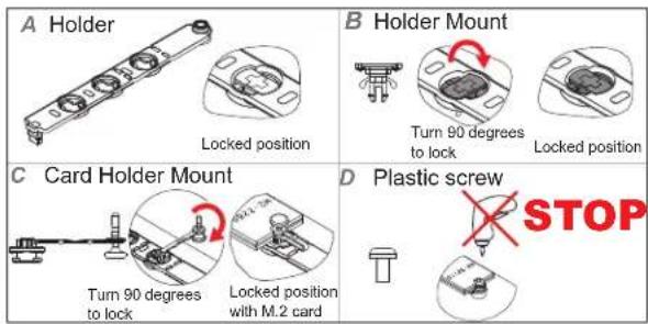
text_image
A Holder Locked position B Holder Mount Turn 90 degrees to lock Locked position C Card Holder Mount Turn 90 degrees to lock Locked position with M.2 card D Plastic screw STOP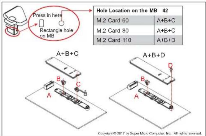
text_image
Press in here Rectangle hole on MB Hole Location on the MB 42 M.2 Card 60 A+B+C M.2 Card 80 A+B+C M.2 Card 110 A+B+D A+B+C A B+D Copyright © 2017 by Super Micro Computer, Inc. All rights reserved.4.3 Front I/O Ports
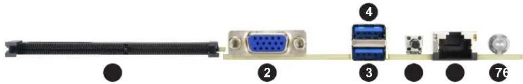
See the figure below for the locations and descriptions of the various I/O ports on the front of the motherboard.
text_image
SUPER X11DPPP-8N CE FCFigure 4-1. Front Panel I/O Port Locations and Definitions
text_image
Diagram showing labeled components of a network interface with connectors and ports| Front Panel I/O Ports | |||
| No. | Description No. | Description | |
| 1. | SIOM (Super I/O Module) | Slot 5. UID (Unit Identifier) | |
| 2. | VGA Port 6. | IPMI LAN | |
| 3. | USB 0 (USB 3.0) | 7. Power Switch (Power-on/Power-Off switch) | |
| 4. | USB 1 (USB 3.0) | ||
Universal Serial Bus (USB) Ports
There are two USB 3.0 ports (USB 0/1) on the I/O front panel. Please refer to the table below for pin-out definitions.
| Front Panel USB 0/1 (3.0)Pin Definitions | ||
| Pin# Definition Pin# Definition | ||
| A1 VBUS B1 Power | ||
| A2 D-B2 USB_N | ||
| A3 D+B3 USB_P | ||
| A4 GND B4 GND | ||
| A5 Stda_SSRX-B5 USB3_RN | ||
| A6 Stda_SSRX+B6 USB3_RP | ||
| A7 GND B7 GND | ||
| A8 Stda_SSTX-B8 USB3_TN | ||
| A9 Stda_SSTX+B9 USB3_TP | ||
IPMI LAN
The IPMI-dedicated LAN port is supported by the AST 2500 BMC (Baseboard Management Controller) It is located next to the power switch on the front panel, and accepts an RJ45 type cable. Please refer to the LED Indicator section below for LAN LED information.
Unit Identifier Switch/UID LED Indicator
A Unit Identifier (UID) switch, located on the front panel, and the UID LED (UIDLED1), located next to the UID switch on the motherboard, provide easy identification of a system that may be in need of service. When you press the UID switch, the UID LED will be turned on. Press the switch again to turn off the UID LED. Please note that the UID switch can also be triggered via IPMI on the motherboard. For more information, please refer to the IPMI User's Guide posted on our website at http://www.supermicro.com.)
| UID Switch Pin Definitions | |
| Pin# | Definition |
| 1 | Ground |
| 2 | Ground |
| 3 | Button In |
| 4 | Button In |
| UID LEDPin Definitions | |
| Color | Status |
| Blue: On | Unit Identified |
VGA Port
A VGA port is located next to the SIOM slot on the front panel. Use this connection for VGA display.
Super I/O Module (SIOM)
A Supermicro proprietary SIOM (Super I/O Module) connector, supported by CPU1, is located at each node's front. This SIOM slot supports PCI-E 3.0 x16 SIOM cards. Connect your SIOM cards into the SIOM slot with approved and qualified for FatTwin SIOM cards, indicated on the SIOM Networking AOC Compatibility Matrix.
Power Switch
A power switch is located next to the IPMP LAN on the front panel. Press this switch to turn on or turn off the system power.
4.4 Jumpers
Explanation of Jumpers
To modify the operation of the motherboard, jumpers are used to choose between optional settings. Jumpers create shorts between two pins to change the function associated with it. Pin 1 is identified with a square solder pad on the printed circuit board. See the motherboard layout page for jumper locations.
Note: On a two-pin jumper, "Closed" means the jumper is on both pins and "Open" indicates the jumper is either on only one pin or has been completely removed.
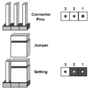
text_image
Connector Pins Jumper Setting 3 2 1 3 2 1CMOS Clear
JBT1 is used to clear CMOS, which will also clear any passwords. Instead of pins, this jumper consists of contact pads to prevent accidentally clearing the contents of CMOS.
To Clear CMOS
- First power down the system and unplug the power cord(s).
- Remove the cover of the chassis to access the motherboard.
- Remove the onboard battery from the motherboard.
- Short the CMOS pads with a metal object such as a small screwdriver for at least four seconds.
- Remove the screwdriver (or shorting device).
- Replace the cover, reconnect the power cord(s) and power on the system.
Notes: Clearing CMOS will also clear all passwords.
Do not use the PW_ON connector to clear CMOS.

JBT1 contact pads
ME Manufacturing Mode
Close pins 1 and 2 of JPME2 to bypass SPI flash security and force the system to use the ME Manufacturing Mode, which will allow you to flash the system firmware from a host server to modify system settings. See the table below for jumper settings.
| ME Manufacturing ModeJumper Settings | |
| Jumper Setting Definition | |
| Pins 1-2 Normal | (Default) |
| Pins 2-3 Manufacturing Mode | |
Watch Dog
JWD1 controls the Watch Dog timer function. Watch Dog is a monitor that can reboot the system when a software application hangs. Close pins 1-2 to allow the Watch Dog to reset the system if an application hangs. Close pins 2-3 to generate a non-maskable interrupt signal for the application that hangs. Watch Dog must also be enabled in BIOS. The default setting is Reset.
Note: When Watch Dog is enabled, the user needs to write their own application software to disable it.
| Watch DogJumper Settings | |
| Jumper Setting Definition | |
| Pins 1-2 Reset (default) | |
| Pins 2-3 NMI | |
| Open Disabled | |
4.5 LED Indicators
IPMI LAN LEDs
The IPMI-dedicated LAN is supported by the BMC, and is located on the front I/O panel of the motherboard. The amber LED on the right indicates activity, while the green LED on the left indicates the speed of the connection. See the table below for more information.
IPMI LAN

Activity LEDLink LED
| IPMI LAN LEDs | ||
| Color/State Definition | ||
| Link (left) Green: Solid 100 Mbps | ||
| Activity (right) Amber: Blinking Active | ||
HDD Activity LED
An HDD Activity LED is located at HDD_LED1 on the on the motherboard. When this LED is blinking, your hard drive devices are active. See the table below for the LED status.
| HDD Activity LED Indicator |
| LED LED State Definition |
| HDD_LED1 Blinking: Green HDD: Active |
BMC Heartbeat LED
LEDM1 on the I/O front panel is used as the BMC heartbeat LED. When the LED is blinking green, BMC is normal. See the table below for the LED status.
| BMC Heartbeat LED Indicator | ||
| LED LED State Definition | ||
| LEDM1 Blinking: Green BMC Normal | ||
Failure LED
When the Failure LED, located at Failure_LED1, is on, an incident of overheating, and/or fan failure has occurred. Please check your system to resolve the situation.
| Failure LED Indicator | |
| LED LED State Definition | |
| Failure_LED1 On: | Red Overheating and/or Fan Failure |
CPLD Heartbeat LED
When the CPLD Heartbeat LED, located at LE1, is blinking green, the onboard CPLD (Complex Programmable Logic Device) is normal. See the table below for the LED status.
| CPLD Heartbeat LED Indicator | |
| LED LED State Definition | |
| LE1 Blinking: Green CPLD: Normal | |
PCI-E/SATA M.2 Hybrid Slot Activity LEDs (LED3/LED4)
The Activity LED indicators for the onboard PCI-E/SATA M.2 hybrid slots (M.2-HC0/ M.2-HC1) are located at LED3 and LED4. When these LED indicators are blinking, these M.2 hybrid slots are active. See the table below for details.
| Activity LED Indicator for PCI-E/SATA M.2 Slots | ||
| LED LED | State Definition | |
| LED3 Blinking: Green PCI-E/SATA M.2 Slot1 (M.2-HC0-J30): Active | ||
| LED4 Blinking: Green PCI-E/SATA M.2 Slot2 (M.2-HC1-J31): Active | ||
Chapter 5
Software
After the hardware has been installed, you can install the Operating System (OS), configure RAID settings and install the drivers.
5.1 Microsoft Windows OS Installation
If you will be using RAID, you must configure RAID settings before installing the Windows OS and the RAID driver. Refer to the RAID Configuration User Guides posted on our website at www.supermicro.com/support/manuals.
Installing the OS
- Create a method to access the MS Windows installation ISO file. That might be a DVD, perhaps using an external USB/SATA DVD drive, or a USB flash drive, or the IPMI KVM console.
- Retrieve the proper RST/RSTe driver. Go to the Supermicro web page for your motherboard and click on "Download the Latest Drivers and Utilities", select the proper driver, and copy it to a USB flash drive.
- Boot from a bootable device with Windows OS installation. You can see a bootable device list by pressing F11 during the system startup.
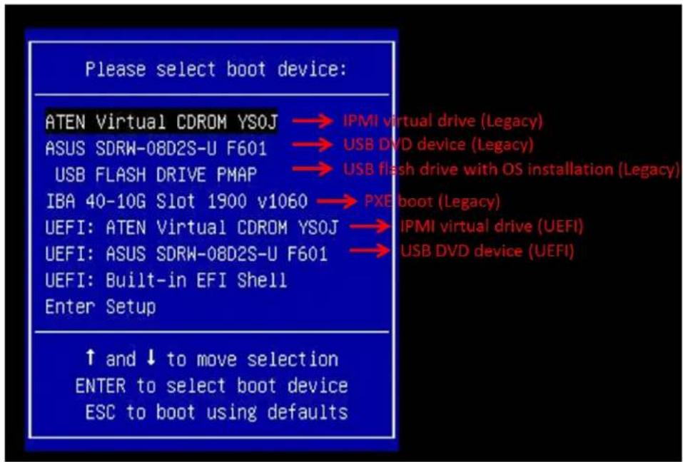
text_image
Please select boot device: ATEN Virtual CDROM YSOJ → IPMI virtual drive (Legacy) ASUS SDRW-08D2S-U F601 → USB DVD device (Legacy) USB FLASH DRIVE PMAP → USB flash drive with OS installation (Legacy) IBA 40-10G Slot 1900 v1060 → PXE boot (Legacy) UEFI: ATEN Virtual CDROM YSOJ → IPMI virtual drive (UEFI) UEFI: ASUS SDRW-08D2S-U F601 → USB DVD device (UEFI) UEFI: Built-in EFI Shell Enter Setup ↑ and ↓ to move selection ENTER to select boot device ESC to boot using defaultsFigure 5-1. Select Boot Device
- During Windows Setup, continue to the dialog where you select the drives on which to install Windows. If the disk you want to use is not listed, click on "Load driver" link at the bottom left corner.
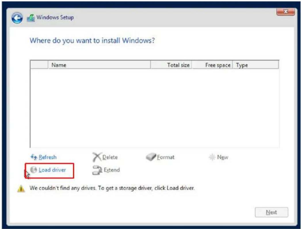
text_image
Where do you want to install Windows? Name Total size Free space Type Refresh Delete Format New Load driver Extend We couldn't find any drives. To get a storage driver, click Load driver. NextFigure 5-2. Load Driver Link
To load the driver, browse the USB flash drive for the proper driver files.
- For RAID, choose the SATA/sSATA RAID driver indicated then choose the storage drive on which you want to install it.
-
For non-RAID, choose the SATA/sSATA AHCI driver indicated then choose the storage drive on which you want to install it.
-
Once all devices are specified, continue with the installation.
- After the Windows OS installation has completed, the system will automatically reboot multiple times.
5.2 Driver Installation
The Supermicro website contains drivers and utilities for your system at https://www.supermicro.com/wftp/driver. Some of these must be installed, such as the chipset driver.
After accessing the website, go into the CDR_Images (in the parent directory of the above link) and locate the ISO file for your motherboard. Download this file to a USB flash drive or a DVD. (You may also use a utility to extract the ISO file if preferred.)
Another option is to go to the Supermicro website at http://www.supermicro.com/products/. Find the product page for your motherboard, and "Download the Latest Drivers and Utilities".
Insert the flash drive or disk and the screenshot shown below should appear.
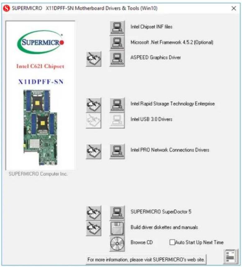
text_image
SUPERMICRO X11DPFF-SN Motherboard Drivers & Tools (Win10) Intel Chipset INF files Microsoft .Net Framework 4.5.2 (Optional) ASPEED Graphics Driver Intel Rapid Storage Technology Enterprise Intel USB 3.0 Drivers Intel PRO Network Connections Drivers SUPERMICRO Computer Inc. SUPERMICRO SuperDoctor 5 Build driver diskettes and manuals Browse CD Auto Start Up Next Time For more information, please visit SUPERMICRO's web site.Figure 5-1. Driver & Tool Installation Screen
Note: Click the icons showing a hand writing on paper to view the readme files for each item. Click the computer icons to the right of these items to install each item (from top to the bottom) one at a time. After installing each item, you must re-boot the system before moving on to the next item on the list. The bottom icon with a CD on it allows you to view the entire contents.
5.3 SuperDoctor® 5
The Supermicro SuperDoctor 5 is a program that functions in a command-line or web-based interface for Windows and Linux operating systems. The program monitors such system health information as CPU temperature, system voltages, system power consumption, fan speed, and provides alerts via email or Simple Network Management Protocol (SNMP).
SuperDoctor 5 comes in local and remote management versions and can be used with Nagios to maximize your system monitoring needs. With SuperDoctor 5 Management Server (SSM Server), you can remotely control power on/off and reset chassis intrusion for multiple systems with SuperDoctor 5 or IPMI. SuperDoctor 5 Management Server monitors HTTP, FTP, and SMTP services to optimize the efficiency of your operation.
Note: The default User Name and Password for SuperDoctor 5 is ADMIN / ADMIN.
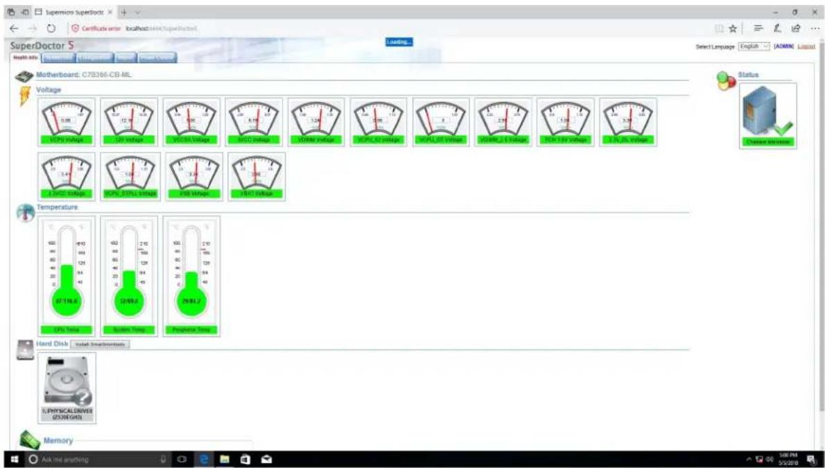
text_image
SuperDoctor 5 Health MIs Certificate error localhost:144k/SuperDoctor Loading... Select Language English (ADMIN) Layout Motherboard: C7B366-CB-ML Voltage 0.08 12.00 14.00 16.00 18.00 20.00 22.00 24.00 26.00 28.00 30.00 32.00 34.00 36.00 38.00 40.00 42.00 44.00 46.00 48.00 50.00 52.00 54.00 56.00 58.00 60.00 62.00 64.00 66.00 68.00 70.00 72.00 74.00 76.00 78.00 80.00 82.00 84.00 86.00 88.00 90.00 92.00 94.00 96.00 98.00 100.00 102.00 104.00 106.00 108.00 110.00 112.00 114.00 116.00 118.00 120.00 122.00 124.00 126.00 128.00 130.00 132.00 134.00 136.00 138.00 140.00 142.00 144.00 146.00 148.00 150.00 152.00 154.00 156.00 158.00 160.00 162.00 164.00 166.00 168.00 170.00 172.00 174.00 176.00 178.00 180.00 182.00 184.00 186.00 188.00 190.00 192.00 194.00 196.00 198.00 200.00 202.00 204.00 206.00 208.00 210.00 212.00 214.00 216.00 218.00 220.00 222.00 224.00 226.00 228.00 230.00 232.00 234.00 236.00 238.00 240.00 242.00 244.0Figure 5-2. SuperDoctor 5 Interface Display Screen (Health Information)
5.4 IPMI
The X11DPFF-SNR supports the Intelligent Platform Management Interface (IPMI). IPMI is used to provide remote access, monitoring and management. There are several BIOS settings that are related to IPMI.
For general documentation and information on IPMI, please visit our website at: http://www.supermicro.com/products/nfo/IPMI.cfm.
Chapter 6
UEFI BIOS
6.1 Introduction
This chapter describes the AMIBIOS™ setup utility for the X11DPFF-SNR motherboard. The BIOS ROM is stored on a chip and can be easily upgraded using a flash program.
Note: Due to periodic changes to the BIOS, some settings may have been added or deleted and might not yet be recorded in this manual. Please refer to the manual download area of our website for any changes to BIOS that may not be reflected in this manual.
Starting the Setup Utility
To enter the BIOS setup utility, press the
The Main BIOS screen has two main frames. The left frame displays all the options that can be configured. "Grayed-out" options cannot be configured. The right frame displays the key legend. Above the key legend is an area reserved for a text message. When an option is selected in the left frame, it is highlighted in white. Often a text message will accompany it. (Note that BIOS has default text messages built in. We retain the option to include, omit, or change any of these text messages.) Settings printed in Bold are the default values.
A "▶" indicates a submenu. Highlighting such an item and pressing the
The BIOS setup utility uses a key-based navigation system called hot keys. Most of these hot keys (
6.2 Main Setup
When you first enter the AMI BIOS setup utility, you will enter the Main setup screen. You can always return to the Main setup screen by selecting the Main tab on the top of the screen. The Main BIOS setup screen is shown below.
| System Date [Thu 07/05/2018] System Time [17:35:26] Supermicro X11DPFF-SN BIOS Version T20180525102358 Build Date 05/25/2018 CPLD Version 01.B1.20 Memory Information Total Memory 393216 MB | Set the Date. Use Tab to switch between Date elements. Default Ranges: Year: 2005-2099 Months: 1-12 Days: dependent on month |
| ++: Select Screen ↑↓: Select Item Enter: Select +/-: Change Opt. F1: General Help F2: Previous Values F3: Optimized Defaults F4: Save & Exit ESC: Exit | |
| Version 2.19.1268. Copyright (C) 2018 American Megatrends, Inc. | |
System Date/System Time
Use this feature to change the system date and time. Highlight System Date or System Time using the arrow keys on the keyboard. Press the
Note: The time is in the 24-hour format. For example, 5:30 P.M. appears as 17:30:00. The date's default value is 01/01/2014 after RTC reset.
Supermicro X11DPFF-SN
BIOS Version
This item displays the version of the BIOS ROM used in the system.
Build Date
This item displays the date when the version of the BIOS ROM used in the system was built.
CPLD Version
This item displays the version of the CPLD (Complex-Programmable Logical Device) used in the system.
Memory Information
Total Memory
This item displays the total size of memory available in the system.
6.3 Advanced Setup Configurations
Use the arrow keys to select the Advanced submenu and press

text_image
Aptio Setup Utility - Copyright (C) 2018 American Megatrends, Inc. Main Advanced Event Logs IPMI Security Boot Save & Exit ▶ Boot Feature ▶ CPU Configuration ▶ Chipset Configuration ▶ Server ME Information ▶ PCH SATA Configuration ▶ PCH SSATA Configuration ▶ PCIe/PCI/PnP Configuration ▶ Super IO Configuration ▶ Serial Port Console Redirection ▶ ACPI Settings ▶ Trusted Computing ▶ iSCSI Configuration ▶ Intel(R) Virtual RAID on CPU Boot Feature Configuration Page ++: Select Screen ↑↓: Select Item Enter: Select +/-: Change Opt. F1: General Help F2: Previous Values F3: Optimized Defaults F4: Save & Exit ESC: Exit Version 2.19.1268. Copyright (C) 2018 American Megatrends, Inc.Warning: Take Caution when changing the Advanced settings. An incorrect value, an incorrect DRAM frequency, or an incorrect BIOS timing setting may cause the system to malfunction. When this occurs, restore the setting to the manufacture default settings.
▶Boot Feature
Quiet Boot
Use this feature to select the screen between displaying POST messages or the OEM logo at bootup. Select Disabled to display the POST messages. Select Enabled to display the OEM logo instead of the normal POST messages. The options are Enabled and Disabled.
Note: POST message is always displayed regardless of the item setting.
Option ROM Messages
Use this feature to set the display mode for Option ROM message settings. Select Keep Current to use the current AddOn ROM display setting. Select Force BIOS to use the display mode that is set by the system BIOS. The options are Force BIOS and Keep Current.
Bootup NumLock State
Use this feature to set the Power-on state for the Numlock key. The options are Off and On.
Wait For 'F1' If Error
Select Enabled to force the system to wait until the 'F1' key is pressed if an error occurs. The options are Disabled and Enabled.
INT19 Trap Response
Interrupt 19 is the software interrupt that handles the boot disk function. When this feature is set to Immediate, the BIOS ROM of the host adaptors will "capture" Interrupt 19 at bootup immediately and allow the drives that are attached to these host adaptors to function as bootable disks. If this feature is set to Postponed, the BIOS ROM of the host adaptors will not capture Interrupt 19 immediately to allow the drives attached to these adaptors to function as bootable devices at bootup. The options are Immediate and Postponed.
Re-try Boot
When EFI (Expansible Firmware Interface) Boot is selected, the system BIOS will automatically reboot the system from an EFI boot device after an initial boot failure. Select Legacy Boot to allow the BIOS to automatically reboot the system from a Legacy boot device after an initial boot failure. The options are Disabled, Legacy Boot, and EFI Boot.
Install Windows 7 USB Support
Select Enabled to use a legacy USB keyboard/mouse in a Windows 7 system that does not have the XHCI driver pre-installed. After you've installed the Windows 7 and XHCI drivers, be sure to set this feature to "Disabled" (default). The options are Disabled and Enabled.
Port 61h Bit-4 Emulation
Select Enabled for I/O Port 61h-Bit 4 emulation support to enhance system compatibility. The options are Enabled and Disabled.
Power Configuration
Watch Dog Function
Select Enabled to allow the Watch Dog timer to reboot the system when it is inactive for more than 5 minutes. The options are Enabled and Disabled.
Restore on AC Power Loss
Use this feature to set the power state after a power outage. Select Power-Off for the system power to remain off after a power loss. Select Power-On for the system power to be turned on after a power loss. Select Last State to allow the system to resume its last power state before a power loss. The options are Stay-Off, Power-On, and Last State.
Power Button Function
This feature controls how the system shuts down when the power button is pressed. Select 4 Seconds Override for the user to power off the system after pressing and holding the power button for 4 seconds or longer. Select Instant Off to instantly power off the system as soon as the user presses the power button. The options are 4 Seconds Override and Instant Off.
Throttle on Power Fail
Select Enabled to decrease system power input by throttling CPU frequency when the power supply fails. The options are Enabled and Disabled.
▶CPU Configuration
Warning: Setting the wrong values in the following sections may cause the system to malfunction.
▶Processor Configuration
The following CPU information will be displayed:
- Processor BSP Revision
- Processor Socket
- Processor ID
- Processor Frequency
- Processor Max Ratio
- Processor Min Ratio
- Microcode Revision
- L1 Cache RAM
- L2 Cache RAM
- L3 Cache RAM
- Processor 0 Version
- Processor 1 Version
Hyper-Threading (ALL)
Select Enable to use Intel Hyper-Threading Technology to enhance CPU performance. The options are Enable and Disable.
Core Enabled
Use this feature to enable or disable CPU cores in the processor specified by the user. Enter 0 to enable all cores available in the processor. The default setting is 0.
Execute Disable Bit (Available if supported by the OS & the CPU)
Select Enable to keep mixed power-on frequency of each CPU socket. The options are Enable and Disable.
Intel Virtualization Technology
Select Enable to use Intel Virtualization Technology which will allow the I/O device assignments to be directly reported to the VMM (Virtual Memory Management) through the DMAR ACPI tables. This feature offers fully-protected I/O resource-sharing across the Intel platforms, providing the user with greater reliability, security and availability in networking and data-sharing. The settings are Enable and Disable.
PPIN Control
Select Unlock/Enable to use the Protected-Processor Inventory Number (PPIN) in the system. The options are Unlock/Enable and Unlock/Disable.
Hardware Prefetcher (Available when supported by the CPU)
If this feature is set to Enable, the hardware prefetcher will prefetch streams of data and instructions from the main memory to the Level 2 (L2) cache to improve CPU performance. The options are Disable and Enable.
Adjacent Cache Prefetch (Available when supported by the CPU)
Select Enable for the CPU to prefetch both cache lines for 128 bytes as comprised. Select Disable for the CPU to prefetch both cache lines for 64 bytes. The options are Disable and Enable.
Note: Please power off and reboot the system for the changes you've made to take effect. Please refer to Intel's website for detailed information.
DCU (Data Cache Unit) Streamer Prefetcher (Available when supported by the CPU)
If this feature is set to Enable, the DCU (Data Cache Unit) streamer prefetcher will prefetch data streams from the cache memory to the DCU (Data Cache Unit) to speed up data accessing and processing for CPU performance enhancement. The options are Disable and Enable.
DCU (Data Cache Unit) IP Prefetcher
If this feature is set to Enable, the IP prefetcher in the DCU (Data Cache Unit) will prefetch IP addresses to improve network connectivity and system performance. The options are Enable and Disable.
LLC Prefetch
If this feature is set to Enable, LLC (hardware cache) prefetching on all CPU threads will be supported. The options are Disable and Enable.
Extended APIC (Advanced Programmable Interrupt Controller)
Based on the Intel Hyper-Threading technology, each logical processor (thread) is assigned 256 APIC IDs (APIDs) in 8-bit bandwidth. When this feature is set to Enable, the APIC ID will be expanded from 8 bits to 16 bits to provide 512 APIDs to each thread to enhance CPU performance. The options are Disable and Enable.
AES-NI
Select Enable to use the Intel Advanced Encryption Standard (AES) New Instructions (NI) to ensure data security. The options are Enable and Disable.
▶Advanced Power Management Configuration
Power Technology
Select Energy Efficient to support power-saving mode. Select Custom to customize system power settings. Select Disabled to disable power-saving settings. The options are Disable, Energy Efficient, and Custom. When this feature is set to Custom, the following items will display.
Power Performance Tuning (Available when "Power Technology" is set to Custom)
Select BIOS Controls EPB to allow the system BIOS to configure Power-Performance Tuning Bias settings listed below. The options are BIOS Controls EPB and OS Controls EPB.
Energy\_PERF\_BIAS\_CFG (Energy Performance BIAS Configuration) Mode (Available when "Power Performance Tuning" is set to BIOS Controls EPB)
Use this feature to set the processor power use policy to achieve the desired operation settings for your machine by prioritizing system performance or energy savings. Select Maximum Performance to maximize system performance (to its highest potential); however, this may result in maximum power consumption as energy is needed to fuel the processor frequency. The higher the performance is, the higher the power consumption will be. Select Power to enhance power efficiency; however, system performance may be impacted as a result. The options are Maximum Performance, Performance, Balanced Performance, Balanced Power, and Power.
▶CPU P State Control (Available when "Power Technology" is set to Custom)
SpeedStep (PStates)
EIST (Enhanced Intel SpeedStep Technology) allows the system to automatically adjust processor voltage and core frequency in an effort to reduce power consumption and heat dissipation. Please refer to Intel's website for detailed information. The options are Disable and Enable.
EIST PSD Function (Available when SpeedStep is set to Enable)
Use this feature to configure the processor's P-State coordination settings. During a P-State, the voltage and frequency of the processor will be reduced when it is in operation. This makes the processor more energy efficient, resulting in further energy gains. The options are HW_ALL, SW_ALL and SW-ANY.
Turbo Mode (Available when SpeedStep is set to Enable)
Select Enable for processor cores to run faster than the frequency specified by the manufacturer. The options are Disable and Enable.
▶Hardware PM (Power Management) State Control (Available when "Power Technology" is set to Custom)
Hardware P-States
If this feature is set to Disable, hardware will choose a P-state setting for the system based on an OS request. If this feature is set to Native Mode, hardware will choose a P-state setting based on OS guidance. If this feature is set to Native Mode with No Legacy Support, hardware will choose a P-state setting independently without OS guidance. The options are Disable, Native Mode, Out of Band Mode, and Native Mode with No Legacy Support.
▶CPU C State Control (Available when "Power Technology" is set to Custom)
Autonomous Core C-State
Select Enable to support Autonomous Core C-State control which will allow the processor core to control its C-State setting automatically and independently. The options are Enable and Disable.
CPU C6 Report
Select Enable to allow the BIOS to report the CPU C6 state (ACPI C3) to the operating system. During the CPU C6 state, power to all caches is turned off. The options are Auto, Enable, and Disable.
Enhanced Halt State (C1E)
Select Enable to enable "Enhanced Halt State" support, which will significantly reduce the CPU's power consumption by minimizing CPU's clock cycles and reduce voltage during a "Halt State." The options are Disable and Enable.
▶Package C State Control (Available when "Power Technology" is set to Custom)
Package C State
Use this feature to set the limit on the C-State package register. The options are C0/1 state, C2 state, C6 (non-Retention) state, C6 (Retention) state, No Limit, and Auto.
▶CPU T State Control (Available when "Power Technology" is set to Custom)
Software Controlled T-States
If this feature is set to Enable, CPU throttling settings will be supported by the software of the system. The options are Disable and Enable.
▶ Chipset Configuration
▶North Bridge
This feature allows the user to configure the settings for the Intel North Bridge.
▶UPI (Ultra Path Interconnect) Configuration
This section displays the following UPI General Configuration information:
• Number of CPU
• Number of Active UPI Link
• Current UPI Link Speed
• Current UPI Link Frequency
• UPI Global MMIO Low Base/Limit
• UPI Global MMIO High Base/Limit
• UPI PCI-E Configuration Base/Size
Degrade Precedence
Use this feature to select the degrading precedence option for UPI (Ultra Path Interconnect) connections. Select Topology Precedent to degrade UPI features if system options are in conflict. Select Feature Precedent to degrade UPI topology if system options are in conflict. The options are Topology Precedence and Feature Precedence.
Link L0p Enable
Select Enable to enable Link L0p. The options are Disable, Enable, and Auto.
Link L1 Enable
Select Enable to enable Link L1 (Level 1 link). The options are Disable, Enable, and Auto.
IO Directory Cache (IODC)
Select Enable for the IODC to generate snoops instead of generating memory lockups for remote IIO (InvIToM) and/or WCiLF (Cores). Select Auto for the IODC to generate snoops (instead of memory lockups) for WCiLF (Cores). The options are Disable, Auto, Enable for Remote InvItoM Hybrid Push, InvItoM AllocFlow, Enable for Remote InvItoM Hybrid AllocNonAlloc, and Enable for Remote InvItoM and Remote WViLF.
SNC (Sub NUMA Cluster)
Select Enable for Sub-NUMA (Non-uniform memory access) Cluster support. Select Auto for 1-cluster or 2-cluster support depending on the satuts of IMC (Integrated Memory Controller) Interleaving. The options are Disable, Enable, and Auto.
XPT Prefetch (Extended Prediction Table Prefetch)
If this feature is set to Enable, a copy of a read request that is sent to the memory controller will be sent to the LLC (Last Level Cache) to improve memory performance. The options are Disable, and Enable.
KTI Prefetch
Select Enable to allow the memory read to start early on a DDR bus to enhance system performance. The options are Enable and Disable.
Local/Remote Threshold
Use this feature to configure the threshold settings for local and remote systems that are connected in the network. The options are Disable, Auto, Low, Medium, and High.
Stale AtoS (A to S)
Select Enable to remove the contents and the structures of the files that are no longer needed in the remote host server but are still in use by the local client machine from Directory A to Directory S in the NFS (Network File System) to optimize system performance. The options are Disable, Enable, and Auto.
LLC Dead Line Alloc
Select Enable to opportunistically fill the deadlines in LLC (Last Level Cache). The options are Enable, Disable, and Auto.
Isoc Mode
Select Enable to enable Isochronous support to meet QoS (Quality of Service) requirements. This feature is especially important for Virtualization Technology. The options are Disable, Enable, and Auto.
▶Memory Configuration
Enforce POR
Select POR to enforce POR restrictions for DDR4 memory frequency and voltage programming settings. The options are POR and Disable.
PPR Type
Use this feature to set the Post Package Repair type. The options are Auto, Hard PPR, Soft PPR, and PPR Disable.
Memory Frequency
Use this feature to set the maximum memory frequency for onboard memory modules. The options are Auto, 1866, 2000, 2133, 2200, 2400, 2600, and 2666.
Data Scrambling for NVDIMM
Select Enable to enable data scrambling for onboard NVDIMM memory to enhance system performance and security. The options are Auto, Disable, and Enable.
Data Scrambling for DDR4
Select Enable to enable data scrambling for DDR4 memory to enhance system performance and security. The options are Auto, Disable, and Enable.
tCCD\_L Relaxation
If this feature is enabled, SPD (Serial Presence Detect) will override tCCD_L ("Column to Column Delay-Long" or "Command to Command Delay-Long" on the column side.) If this feature is set to Disable, tCCD_L will be enforced based on the memory frequency. The options are Disable, and Auto.
tRWSR Relaxation
Select Enable to use the same tRWSR DDR timing setting among all memory channels, in which case, the worst value among all channels will be used. Select Disable to use different values for the tRWSR DDR timing settings for different channels as trained. The options are Disable and Enable.
Enable ADR (Available when an NVDIMM is detected)
Select Enable for ADR (Automatic Diagnostic Repository) support to enhance memory performance. The options are Enable and Disable.
Erase-Arm NVDIMMs (Available when an NVDIMM is detected & the item above: Enable ADR is set to Enable)
If this feature is set to Enable, the function that arms the NVDIMMs for save operations in the event of a power loss will be removed. The options are Enable and Disable.
Restore NVDIMMs (Available when an NVDIMM is detected & the item above: Enable ADR is set to Enable)
Select Enable to restore the functionality and the features of NVDIMMs. The options are Enable and Disable.
Interleave NVDIMMs (Available when an NVDIMM is detected & the item above: Enable ADR is set to Enable)
Select Enable for NVDIMM interleaving support to enhance NVDIMM performance. The options are Enable and Disable.
Reset Trigger ADR (Available when an NVDIMM is detected & the item above: Enable ADR is set to Enable)
Upon system power loss, an ADR (Automatic Diagnostic Repository) sequence will be triggered to allow ADR to flush the write-protected data buffers in the memory controller and place the DRAM in self-refresh. When this process is complete, the NVDIMM will then take control of the DRAM and transfer the contents to the onboard Flash. After the transfer is complete, the NVDIMM goes into a zero power state. The data transferred will be retained for the duration specified by the flash. The options are Enable and Disable.
S5 Trigger ADR (Available when an NVDIMM is detected & the item above: Enable ADR is set to Enable)
Select Enabled to support S5-Triggered ADR to enhance system performance and data integrity. The options are Disabled and Enabled.
2X Refresh
Select Enable for memory 2X refresh support to enhance memory performance. The options are Enable and Auto.
Page Policy
Use this feature to set the page policy for onboard memory support. The options are Closed, Adaptive, and Auto.
IMC Interleaving
Use this feature to configure interleaving settings for the IMC (Integrated Memory Controller), which will improve memory performance. The options are 1-way Interleave, 2-way Interleave, and Auto.
▶Memory Topology
This item displays the information of onboard memory modules as detected by the BIOS.
• P1DIMMA1/P1DIMMB1/P1DIMMC1/P1DIMMD1/P1DIMME1/P1DIMMF1
• P2DIMMA1/P2DIMMB1/P2DIMMC1/P2DIMMD1/P2DIMME1/P2DIMMF1
▶Memory RAS (Reliability\_Availability\_Serviceability) Configuration
Use this submenu to configure the following Memory RAS settings.
Static Virtual Lockstep Mode
Select Enable to support the Static Virtual Lockstep mode to enhance memory performance. The options are Enable and Disable.
Mirror Mode
Use this feature to configure the mirror mode settings for all 1LM/2LM memory modules installed in the system which will create a duplicate copy of data stored in the memory to increase memory security, but it will reduce the memory capacity into half. The options are Disable, Mirror Mode 1LM, and Mirror Mode 2LM.
Note: The setting for this feature can be edited when the item below: ADDDC Sparing is set to Disable.
UEFI ARM Mirror
If this feature is set to Enable, mirror mode configuration settings for UEFI-based Address Range memory will be enabled upon system boot. This will create a duplicate copy of data stored in the memory to increase memory security, but it will reduce the memory capacity into half. The options are Disable and Enable.
Note: The setting for this feature can be edited when both ADDDC Sparing and Mirror Mode are set to Disable.
Memory Rank Sparing
Select Enable to support memory-rank sparing to optimize memory performance. The options are Enable and Disable.
Notes. 1: This feature can will not be available when the item: Memory Mirror Mode is set to Enabled. 2: When this feature: Memory Rank Sparing is set to Enabled, the following item will be available:
Multi Rank Sparing (Available when Memory Rank Sparing is set to Enable)
Use this feature to set the multiple rank sparing number. The default setting and the maximum is two ranks per channel. The options are One Rank and Two Rank.
Correctable Error Threshold
Use this item to enter the threshold value for correctable memory errors. The default setting is 100.
Intel Run Sure (Available when this feature is supported by the CPU)
Select Enable to support Intel® Run Sure Technology to further enhance critical data protection and to increase system uptime and resiliency. The options are Enable and Disable.
SDDC Plus One (Available when this feature is supported by the CPU & the item: Intel Run Sure is set to Disable)
SDDC (Single Device Data Correction) checks and corrects single-bit or multiple-bit (4-bit max.) memory faults that affect an entire single x4 DRAM device. SDDC Plus One is the enhanced feature to SDDC. SDDC+1 will spare the faulty DRAM device out after an SDDC event has occurred. After the event, the SDDC+1 ECC mode is enabled to protect against any additional memory failure caused by a 'single-bit' error in the same memory rank. The options are Disable and Enable*. (The option "Enable" can be set as default when it is supported by the motherboard.)
ADDDC (Adaptive Double Device Data Correction) Sparing
Select Enable for Adaptive Double Device Data Correction (ADDDC) support, which will not only provide memory error checking and correction but will also prevent the system from issuing a performance penalty before a device fails. Please note that virtual lockstep mode will only start to work for ADDDC after a faulty DRAM module is spared. The options are Enable* and Disable. (The option "Enable" can be set as default when it is supported by the motherboard.)
Note: This feature is available when Intel Run Sure and Mirror Mode are both set to Disable.
Patrol Scrub
Patrol Scrubbing is a process that allows the CPU to correct correctable memory errors detected in a memory module and send the corrections to the requestor (the original source). When this item is set to Enable, the IO hub will read and write back one cache line every 16K cycles if there is no delay caused by internal processing. By using this method, roughly 64 GB of memory behind the IO hub will be scrubbed every day. The options are Enable and Disable.
Patrol Scrub Interval
Use this item to specify the number of hours (between 0 to 24) required for the system to complete a full patrol scrubbing. Enter 0 for patrol scrubbing to be performed automatically. The default setting is 24.
Note: This item is hidden when Patrol Scrub item is set to Disable.
▶IIO Configuration
EV DFX (Device Function On-Hide) Features
When this feature is set to Enable, the EV_DFX Lock Bits that are located in a processor will always remain clear during electric tuning. The options are Disable and Enable.
▶CPU1 Configuration/CPU2 Configuration
IOU0 (IIO PCIe Br1)
This feature configures the PCI-E Bifuraction setting for a PCI-E port specified by the user. The options are x4x4x4x4, x4x4x8, x8x4x4, x8x8, x16, and Auto.
IOU1 (IIO PCIe Br2)
This feature configures the PCI-E Bifuraction setting for a PCI-E port specified by the user. The options are x4x4x4x4, x4x4x8, x8x4x4, x8x8, x16, and Auto.
IOU2 (IIO PCIe Br3)
This feature configures the PCI-E Bifuraction setting for a PCI-E port specified by the user. The options are x4x4x4x4, x4x4x8, x8x4x4, x8x8, x16, and Auto.
MCP0 (IIO PCIe Br4)
This feature configures the PCI-E Bifuraction setting for a PCI-E port specified by the user. The options are x16 and Auto.
MCP1 (IIO PCIe Br5)
This feature configures the PCI-E Bifuraction setting for a PCI-E port specified by the user. The options are x16 and Auto.
▶CPU1 PCI-E Br0D00F0 - Port 0/DMI (Available for CPU 1 Configuration only)
Link Speed
This feature configures the link speed of a PCI-E port specified by the user. The options are Auto, Gen 1 (Generation 1) (2.5 GT/s), Gen 2 (Generation 2) (5 GT/s), and Gen 3 (Generation 3) (8 GT/s)
The following information will also be displayed:
• PCI-E Port Link Status
• PCI-E Port Link Max
• PCI-E Port Link Speed
PCI-E Port Max (Maximum) Payload Size (Available for CPU 1 Configuration only)
Select Auto for the BIOS to automatically set the maximum payload value for a PCI-E device specified by to user to enhance system performance. The options are Auto, 128B, and 256B.
▶IOAT Configuration
Disable TPH (TLP Processing Hint)
TPH is used for data-tagging with a destination ID among other important attributes. It can send critical data to a particular cache without writing through to memory. Select No in this item for TLP Processing Hint support, which will allow a "TPL request" to provide "hints" to help optimize the processing of each transaction occurred in the target memory space. The options are Yes and No.
Prioritize TPH (TLP Processing Hint) (Not Available when the item: Disable TPH is set to Yes)
Select Yes to prioritize the TPL requests that will allow the "hints" to be sent to help facilitate and optimize the processing of certain transactions in the system memory. The options are Enable and Disable.
Relaxed Ordering
Select Enable to allow certain transactions to be processed and completed before other transactions that have already been enqueued. The options are Disable and Enable.
▶Intel® VT for Directed I/O (VT-d)
Intel® VT for Directed I/O (VT-d)
Select Enable to use Intel Virtualization Technology support for Direct I/O VT-d by reporting the I/O device assignments to the VMM (Virtual Machine Monitor) through the DMAR ACPI tables. This feature offers fully-protected I/O resource sharing across Intel platforms, providing greater reliability, security and availability in networking and data-sharing. The options are Enable and Disable.
ACS Control (Available when the item: Intel VT for Directed I/O ((VT-d)) is set to Enable)
Use this feature to program Access Control Services (ACS) to the PCI-E Root Port Bridges. The options are Enable and Disable.
Interrupt Remapping (Available when the item: Intel VT for Directed I/O ((VT-d)) is set to Enable)
Select Enable for Interrupt Remapping support to enhance system performance. The options are Enable and Disable.
PassThrough DMA (Available when the item: Intel VT for Directed I/O ((VT-d)) is set to Enable)
Select Enable for the Non-Iscoh VT-d engine to pass through DMA (Direct Memory Access) to enhance system performance. The options are Enable and Disable.
ATS (Available when the item: Intel VT for Directed I/O ((VT-d)) is set to Enable)
Select Enable to enable ATS (Address Translation Services) support for the Non-Iscoh VT-d engine to enhance system performance. The options are Enable and Disable.
Posted Interrupt (Available when the item: Intel VT for Directed I/O ((VT-d)) is set to Enable)
Select Enable to support VT_D Posted Interrupt which will allow external interrupts to be sent directly from a direct-assigned device to a client machine in the non-root mode to improve virtualization efficiency by simplifying interrupt migration and lessening the need of physical interrupts. The options are Enable and Disable.
Coherency Support (Non-Isoch) (Available when the item: Intel VT for Directed I/O ((VT-d)) is set to Enable)
Select Enable for the Non-Iscoh VT-d engine to pass through DMA (Direct Memory Access) to enhance system performance. The options are Enable and Disable.
▶Intel® VMD Technology
▶Intel® VMD for Volume Management Device on CPU1
VMD Config for PStack1
Intel® VMD for Volume Management Device
Select Enable to use the Intel Volume Management Device Technology for this stack. The options are Disable and Enable.
*If the item "Intel VMD for Volume Management Device" above is set to Enable, the following items will be displayed:
VMD port 2A\~VMD port 2D (Available when the device is detected by the system)
Select Enable to use the Intel Volume Management Device Technology for this specific root port. The options are Disable and Enable.
Hot Plug Capable (Available when the device is detected by the system)
Use this feature to enable hot plug support for PCI-E root ports 2A\~2D. The options are Disable and Enable.
VMD Config for PStack2
Intel® VMD for Volume Management Device
Select Enable to use the Intel Volume Management Device Technology for this stack. The options are Disable and Enable.
*If the item "Intel VMD for Volume Management Device" above is set to Enable, the following items will be displayed:
VMD port 3C\~VMD port 3D (Available when the device is detected by the system)
Select Enable to use the Intel Volume Management Device Technology for this specific root port. The options are Disable and Enable.
Hot Plug Capable (Available when the device is detected by the system)
Use this feature to enable hot plug support for PCI-E root ports 3A\~3D. The options are Disable and Enable.
Intel® VMD for Volume Management Device on CPU2
VMD Config for PStack0
Intel® VMD for Volume Management Device
Select Enable to use the Intel Volume Management Device Technology for this stack. The options are Disable and Enable.
*If the item "Intel VMD for Volume Management Device" above is set to Enable, the following items will be displayed:
VMD port 1A\~VMD port 1B (Available when the device is detected by the system)
Select Enable to use the Intel Volume Management Device Technology for this specific root port. The options are Disable and Enable.
Hot Plug Capable (Available when the device is detected by the system)
Use this feature to enable hot plug support for PCI-E root ports 1A\~1B. The options are Disable and Enable.
VMD Config for PStack1
Intel® VMD for Volume Management Device
Select Enable to use the Intel Volume Management Device Technology for this stack. The options are Disable and Enable.
*If the item "Intel VMD for Volume Management Device" above is set to Enable, the following items will be displayed:
VMD port 2A\~VMD port 2D (Available when the device is detected by the system)
Select Enable to use the Intel Volume Management Device Technology for this specific root port. The options are Disable and Enable.
Hot Plug Capable (Available when the device is detected by the system)
Use this feature to enable hot plug support for PCI-E root ports 2A\~2D. The options are Disable and Enable.
VMD Config for PStack2
Intel® VMD for Volume Management Device
Select Enable to use the Intel Volume Management Device Technology for this stack. The options are Disable and Enable.
*If the item "Intel VMD for Volume Management Device" above is set to Enable, the following items will be displayed:
VMD port 3A\~VMD port 3D (Available when the device is detected by the system)
Select Enable to use the Intel Volume Management Device Technology for this specific root port. The options are Disable and Enable.
Hot Plug Capable (Available when the device is detected by the system)
Use this feature to enable hot plug support for PCI-E root ports 3A\~3D. The options are Disable and Enable.
II0-PCI-E Express Global Options
PCI-E Completion Timeout Disable
Use this feature to enable PCI-E Completion Timeout support for electric tuning. The options are Yes, No, and Per-Port.
▶ South Bridge
The following South Bridge information will display:
- USB Module Version
- USB Devices
Legacy USB Support
Select Enabled to support onboard legacy USB devices. Select Auto to disable legacy support if there are no legacy USB devices present. Select Disable to have all USB devices available for EFI applications only. The options are Enabled, Disabled and Auto.
XHCI Hand-Off
This is a work-around solution for operating systems that do not support XHCI (Extensible Host Controller Interface) hand-off. The XHCI ownership change should be claimed by the XHCI driver. The options are Enabled and Disabled.
Port 60/64 Emulation
Select Enabled for I/O port 60h/64h emulation support, which in turn, will provide complete legacy USB keyboard support for the operating systems that do not support legacy USB devices. The options are Enabled and Disabled.
PCI-E PLL SSC
Select Enable for PCH PCI-E Spread Spectrum Clocking support, which will allow the BIOS to monitor and attempt to reduce the level of Electromagnetic Interference caused by the components whenever needed. The options are Enable and Disable.
▶Server ME (Management Engine) Configuration
This feature displays the following system ME configuration settings.
- General ME Configuration
• Operational Firmware Version - Backup Firmware Version
• Recovery Firmware Version
• ME Firmware Status #1/ME Firmware Status #2 - Current State
- Error Code
▶PCH SATA Configuration
When this submenu is selected, the AMI BIOS automatically detects the presence of the SATA devices that are supported by the Intel PCH chip and displays the following items:
SATA Controller
This item enables or disables the onboard SATA controller supported by the Intel PCH chip. The options are Enable and Disable.
Configure SATA as (Available when the item above: SATA Controller is enabled)
Select AHCI to configure a SATA drive specified by the user as an AHCI drive. Select RAID to configure a SATA drive specified by the user as a RAID drive. The options are AHCI and RAID. (Note: This item is hidden when the SATA Controller item is set to Disabled.)
SATA HDD Unlock (Available when the item: SATA Controller is set to Enable)
Select Enable to unlock SATA HDD password in the OS. The options are Enable and Disable.
SATA RSTe Boot Info (Available when the item: "Configure SATA as" is set to RAID)
Select Enable to provide the full int13h support for SATA controller attached devices. The options are Disable and Enable.
Aggressive Link Power Management
When this item is set to Enabled, the SATA AHCI controller manages the power use of the SATA link. The controller will put the link in a low power mode during an extended period of I/O inactivity, and will return the link to an active state when I/O activity resumes. The options are Enable and Disable.
SATA RAID Option ROM/UEFI Driver (Available when the item: Configure SATA as is set to RAID)
Select EFI to load the EFI driver for system boot. Select Legacy to load a legacy driver for system boot. The options are Disable, EFI, and Legacy.
(I-)SATA Port 0 - SATA Port 7
Hot Plug
Select Enable to support Hot-plugging for the device installed on a selected SATA port which will allow the user to replace the device installed in the slot without shutting down the system. The options are Enable and Disable.
Spin Up Device
On an edge detect from 0 to 1, set this item to allow the SATA device installed on the SATA port specified by the user to start a COMRESET initialization. The options are Enable and Disable.
SATA Device Type
Use this item to specify if the device installed on the SATA port selected by the user should be connected to a Solid State drive or a Hard Disk Drive. The options are Hard Disk Drive and Solid State Drive.
▶ PCH sSATA Configuration
When this submenu is selected, AMI BIOS automatically detects the presence of the sSATA devices that are supported by the PCH sSATA controller and displays the following items:
sSATA Controller
This item enables or disables the onboard sSATA controller supported by the Intel PCH. The options are Enable and Disable.
Configure sSATA as
Select AHCI to configure an sSATA drive specified by the user as an AHCI drive. Select RAID to configure an sSATA drive specified by the user as a RAID drive. The options are AHCI and RAID. (Note: This item is hidden when the sSATA Controller item is set to Disabled.)
SATA HDD Unlock (Available when the item: sSATA Controller is set to Enable)
Select Enable to unlock sSATA HDD password in the OS. The options are Enable and Disable.
sSATA RSTe Boot Info (Available when the item: "Configure sSATA as" is set to RAID)
Select Enable to provide the full int13h support for sSATA controller attached devices. The options are Disable and Enable.
Aggressive Link Power Management
When this item is set to Enable, the sSATA AHCI controller manages the power use of the SATA link. The controller will put the link in a low power mode during an extended period of I/O inactivity, and will return the link to an active state when I/O activity resumes. The options are Disable and Enable.
sSATA RAID Option ROM/UEFI Driver (Available when the item: Configure sSATA as is set to RAID)
Select EFI to load the EFI driver for system boot. Select Legacy to load a legacy driver for system boot. The options are Disable, EFI, and Legacy.
sSATA Port 0 - sSATA Port 3
Hot Plug
Select Enable to support Hot-plugging for the device installed on an sSATA port selected by the user which will allow the user to replace the device installed in the slot without shutting down the system. The options are Disable and Enabled.
Spin Up Device
On an edge detect from 0 to 1, set this item to allow the sSATA device installed on the sSATA port specified by the user to start a COMRESET initialization. The options are Enable and Disable.
sSATA Device Type
Use this item to specify if the device installed on the sSATA port specified by the user should be connected to a Solid State drive or a Hard Disk Drive. The options are Hard Disk Drive and Solid State Drive.
▶PCIe/PCI/PnP Configuration
The following PCI information will be displayed:
• PCI Bus Driver Version
• PCI Devices Common Settings
Above 4G Decoding (Available if the system supports 64-bit PCI decoding)
Select Enabled to decode a PCI device that supports 64-bit in the space above 4G Address. The options are Enabled and Disabled.
SR-IOV Support (Available if the system supports Single-Root Virtualization)
Select Enabled for Single-Root IO Virtualization support. The options are Enabled and Disabled.
MMIO High Base
Use this feature to select the base memory size according to memory-address mapping for the IO hub. The base memory size must be between 4032G to 4078G. The options are 56T, 40T, 24T, 16T, 4T, 2T and 1T.
MMIO High Granularity Size
Use this feature to select the high memory size according to memory-address mapping for the IO hub. The options are 1G, 4G, 16G, 64G, 256G, and 1024G.
Maximum Read Request
Select Auto for the system BIOS to automatically set the maximum size for a read request for a PCI-E device to enhance system performance. The options are Auto, 128 Bytes, 256 Bytes, 512 Bytes, 1024 Bytes, 2048 Bytes, and 4096 Bytes.
MMCFG Base
This feature determines the lowest MMCFG (Memory-Mapped Configuration) base assigned to PCI devices. The options are 1G, 1.5G, 1.75G. 2G, 2.25G, and 3G.
NVMe Firmware Source
This feature determines which type of the NVMe firmware should be used in your system. The options are Vendor Defined Firmware and AMI Native Support.
VGA Priority
This feature selects the graphics device to be used as the primary video display for system boot. The options are Auto, Onboard and Offboard.
CPU1 Slot1 PCI-E 3.0 x16 OPROM/CPU1 Slot2 PCI-E 3.0 x8 OPROM/ Slot/SIOM: CPU1 PCI-E 3.0 x16 OPROM
Select EFI to allow the user to boot the computer using an EFI (Expansible Firmware Interface) device installed on the PCI-E slot specified by the user. Select Legacy to allow the user to boot the computer using a legacy device installed on the PCI-E slot specified by the user. The options are Disabled, Legacy and EFI. (Note: Riser card names may differ in each system.)
Bus Master Enable
Select Enabled to enable the Bus Driver Master bit. The options are Disabled and Enabled.
Onboard NVMe1 Option ROM/Onboard NVMe2 Option ROM/Onboard NVMe3 Option ROM/Onboard NVMe4 Option ROM
Select Disabled to deactivate the selected slot, Legacy to activate the slot in legacy mode, and EFI to activate the slot in EFI mode. The options are Disabled, Legacy, and EFI.
Onboard Video Option ROM
Use this feature to select the Onboard Video Option ROM type. The options are Disabled, Legacy and EFI.
▶ Network Stack Configuration
Network Stack
Select Enabled to enable PXE (Preboot Execution Environment) or UEFI (Unified Extensible Firmware Interface) for network stack support. The options are Enabled and Disabled.
*If "Network Stack" is set to Enabled, the following items will display:
Ipv4 PXE Support
Select Enabled to enable lpv4 PXE boot support. If this feature is disabled, it will not create the lpv4 PXE boot option. The options are Disabled and Enabled.
Ipv4 HTTP Support
Select Enabled to enable lpv4 HTTP boot support. If this feature is disabled, it will not create the lpv4 HTTP boot option. The options are Enabled and Disabled.
Ipv6 PXE Support
Select Enabled to enable lpv6 PXE boot support. If this feature is disabled, it will not create the lpv6 PXE boot option. The options are Disabled and Enabled.
Ipv6 HTTP Support
Select Enabled to enable lpv6 HTTP boot support. If this feature is disabled, it will not create the lpv6 HTTP boot option. The options are Enabled and Disabled.
PXE Boot Wait Time
Use this feature to select the wait time to press the
Media Detect Time
Use this feature to select the wait time in seconds for the BIOS ROM to detect the LAN media (Internet connection or LAN port). The default is 1.
▶ Super IO Configuration
Super IO Chip AST2500
▶ Serial Port 1 Configuration
Serial Port 1
Select Enabled to enable the onboard serial port specified by the user. The options are Enabled and Disabled.
Device Settings (Not Available when Serial Port 1 is set to Disabled.)
This feature displays the base I/O port address and the Interrupt Request address of a serial port specified by the user.
Change Settings (Not Available when Serial Port 1 is set to Disabled.)
This feature specifies the base I/O port address and the Interrupt Request address of Serial Port 1. Select Auto for the BIOS to automatically assign the base I/O and IRQ address to a serial port specified.
The options for Serial Port 1 are Auto, (IO=3F8h; IRQ=4), (IO=2F8h; IRQ=4), (IO=3E8h; IRQ=4), and (IO=2E8h; IRQ=4).
▶ Serial Port 2 Configuration
Serial Port 2
Select Enabled to enable the onboard serial port specified by the user. The options are Enabled and Disabled.
Device Settings (Not Available when Serial Port 2 is set to Disabled.)
This feature displays the base I/O port address and the Interrupt Request address of a serial port specified by the user.
Change Settings (Not Available when Serial Port 2 is set to Disabled.)
This feature specifies the base I/O port address and the Interrupt Request address of Serial Port 2. Select Auto for the BIOS to automatically assign the base I/O and IRQ address to a serial port specified. The options for Serial Port 2 are Auto, (IO=2F8h; IRQ=3), (IO=3F8h; IRQ=3), (IO=3E8h; IRQ=3), and (IO=2E8h; IRQ=3).
Serial Port 2 Attribute
Select SOL to use COM Port 2 as a Serial_Over_LAN (SOL) port for console redirection. The options are COM and SOL.
▶Serial Port Console Redirection
COM 1 Console Redirection
Select Enabled to enable COM Port 1 for Console Redirection, which will allow a client machine to be connected to a host machine at a remote site for networking. The options are Enabled and Disabled.
*If the item above set to Enabled, the following items will become available for configuration:
▶ Console Redirection Settings (when COM1 Console Redirection is Enabled)
Terminal Type
Use this feature to select the target terminal emulation type for Console Redirection. Select VT100 to use the ASCII Character set. Select VT100+ to add color and function key support. Select ANSI to use the Extended ASCII Character Set. Select VT-UTF8 to use UTF8 encoding to map Unicode characters into one or more bytes. The options are ANSI, VT100, VT100+, and VT-UTF8.
Bits Per second
Use this feature to set the transmission speed for a serial port used in Console Redirection. Make sure that the same speed is used in the host computer as well as the client computer. A lower transmission speed may be required for long and busy lines. The options are 9600, 19200, 38400, 57600 and 115200 (bits per second).
Data Bits
Use this feature to set the data transmission size for Console Redirection. The options are 7 (Bits) and 8 (Bits).
Parity
A parity bit can be sent along with regular data bits to detect data transmission errors. Select Even if the parity bit is set to 0, and the number of 1's in data bits is even. Select Odd if the parity bit is set to 0, and the number of 1's in data bits is odd. Select None if you do not want to send a parity bit with your data bits in transmission. Select Mark to add a mark as a parity bit to be sent along with the data bits. Select Space to add a Space as a parity bit to be sent with your data bits. The options are None, Even, Odd, Mark and Space.
Stop Bits
A stop bit indicates the end of a serial data packet. Select 1 Stop Bit for standard serial data communication. Select 2 Stop Bits if slower devices are used. The options are 1 and 2.
Flow Control
Use this feature to set the flow control for Console Redirection to prevent data loss caused by buffer overflow. Send a "Stop" signal to stop sending data when the receiving buffer is full. Send a "Start" signal to start sending data when the receiving buffer is empty. The options are None and Hardware RTS/CTS.
VT-UTF8 Combo Key Support
Select Enabled to enable VT-UTF8 Combination Key support for ANSI/VT100 terminals. The options are Enabled and Disabled.
Recorder Mode
Select Enabled to capture the data displayed on a terminal and send it as text messages to a remote server. The options are Disabled and Enabled.
Resolution 100x31
Select Enabled for extended-terminal resolution support. The options are Disabled and Enabled.
Legacy OS Redirection Resolution
Use this feature to select the number of rows and columns used in Console Redirection for legacy OS support. The options are 80x24 and 80x25.
Putty KeyPad
This feature selects Function Keys and KeyPad settings for Putty, which is a terminal emulator designed for the Windows OS. The options are VT100, LINUX, XTERMR6, SCO, ESCN, and VT400.
Redirection After BIOS Post
Use this feature to enable or disable legacy Console Redirection after BIOS POST. When the option - Bootloader is selected, legacy Console Redirection is disabled before booting the OS. When the option-Always Enable is selected, legacy Console Redirection remains enabled upon OS bootup. The options are Always Enable and Bootloader.
SOL (Serial-Over-LAN)
Console Redirection (for SOL/COM2)
Select Enabled to use the SOL port for Console Redirection. The options are Enabled and Disabled.
*If the item above set to Enabled, the following items will become available for user's configuration:
▶ Console Redirection Settings (for SOL/COM2)
Use this feature to specify how the host computer will exchange data with the client computer, which is the remote computer used by the user.
Terminal Type
Use this feature to select the target terminal emulation type for Console Redirection. Select VT100 to use the ASCII Character set. Select VT100+ to add color and function key support. Select ANSI to use the Extended ASCII Character Set. Select VT-UTF8 to use UTF8 encoding to map Unicode characters into one or more bytes. The options are ANSI, VT100, VT100+, and VT-UTF8.
Bits Per second
Use this feature to set the transmission speed for a serial port used in Console Redirection. Make sure that the same speed is used in the host computer and the client computer. A lower transmission speed may be required for long and busy lines. The options are 9600, 19200, 38400, 57600 and 115200 (bits per second).
Data Bits
Use this feature to set the data transmission size for Console Redirection. The options are 7 (Bits) and 8 (Bits).
Parity
A parity bit can be sent along with regular data bits to detect data transmission errors. Select Even if the parity bit is set to 0, and the number of 1's in data bits is even. Select Odd if the parity bit is set to 0, and the number of 1's in data bits is odd. Select None if you do not want to send a parity bit with your data bits in transmission. Select Mark to add a mark as a parity bit to be sent along with the data bits. Select Space to add a Space as a parity bit to be sent with your data bits. The options are None, Even, Odd, Mark and Space.
Stop Bits
A stop bit indicates the end of a serial data packet. Select 1 Stop Bit for standard serial data communication. Select 2 Stop Bits if slower devices are used. The options are 1 and 2.
Flow Control
Use this feature to set the flow control for Console Redirection to prevent data loss caused by buffer overflow. Send a "Stop" signal to stop sending data when the receiving buffer is full. Send a "Start" signal to start data-sending when the receiving buffer is empty. The options are None and Hardware RTS/CTS.
VT-UTF8 Combo Key Support
Select Enabled to enable VT-UTF8 Combination Key support for ANSI/VT100 terminals. The options are Enabled and Disabled.
Recorder Mode
Select Enabled to capture the data displayed on a terminal and send it as text messages to a remote server. The options are Disabled and Enabled.
Resolution 100x31
Select Enabled for extended-terminal resolution support. The options are Disabled and Enabled.
Legacy OS Redirection Resolution
Use this feature to select the number of rows and columns used in Console Redirection for legacy OS support. The options are 80x24 and 80x25.
Putty KeyPad
This feature selects Function Keys and KeyPad settings for Putty, which is a terminal emulator designed for the Windows OS. The options are VT100, LINUX, XTERMR6, SCO, ESCN, and VT400.
Redirection After BIOS Post
Use this feature to enable or disable legacy Console Redirection after BIOS POST (Power-On Self-Test). When this feature is set to Bootloader, legacy Console Redirection is disabled before booting the OS. When this feature is set to Always Enable, legacy Console Redirection remains enabled upon OS boot. The options are Always Enable and Bootloader.
Legacy Console Redirection
Legacy Console Redirection Port
Use the feature to select the COM port to display redirection of Legacy OS and Legacy OPROM messages. The options are COM1 and SOL/COM2.
Serial Port for Out-of-Band Management/Windows Emergency Management Services (EMS)
The submenu allows the user to configure Console Redirection settings to support Out-of-Band Serial Port management.
Console Redirection (for EMS)
Select Enabled to use a COM port selected by the user for EMS Console Redirection. The options are Disabled and Enabled.
*If the item above set to Enabled, the following items will become available for user's configuration:
▶(EMS) Console Redirection Settings
Out-of-Band Management Port
The feature selects a serial port in a client server to be used by the Windows Emergency Management Services (EMS) to communicate with a remote host server. The options are COM1 (Console Redirection) and SOL (Console Redirection).
Terminal Type
Use this feature to select the target terminal emulation type for Console Redirection. Select VT100 to use the ASCII character set. Select VT100+ to add color and function key support. Select ANSI to use the extended ASCII character set. Select VT-UTF8 to use UTF8 encoding to map Unicode characters into one or more bytes. The options are ANSI, VT100, VT100+, and VT-UTF8.
Bits Per Second
This feature sets the transmission speed for a serial port used in Console Redirection. Make sure that the same speed is used in both host computer and the client computer. A lower transmission speed may be required for long and busy lines. The options are 9600, 19200, 57600, and 115200 (bits per second).
Flow Control
Use this feature to set the flow control for Console Redirection to prevent data loss caused by buffer overflow. Send a "Stop" signal to stop data-sending when the receiving buffer is full. Send a "Start" signal to start data-sending when the receiving buffer is empty. The options are None, Hardware RTS/CTS, and Software Xon/Xoff.
The setting for each these features is displayed:
Data Bits, Parity, Stop Bits
▶ ACPI Settings
Use this feature to configure Advanced Configuration and Power Interface (ACPI) power management settings for your system.
NUMA Support (Available when the OS supports this feature)
Select Enabled to enable Non-Uniform Memory Access support to enhance system performance. The options are Enabled and Disabled.
WHEA Support
Select Enabled to support the Windows Hardware Error Architecture (WHEA) platform and provide a common infrastructure for the system to handle hardware errors within the Windows OS environment to reduce system crashes and to enhance system recovery and health monitoring. The options are Enabled and Disabled.
High Precision Event Timer
Select Enabled to activate the High Precision Event Timer (HPET) that produces periodic interrupts at a much higher frequency than a Real-time Clock (RTC) does in synchronizing multimedia streams, providing smooth playback and reducing the dependency on other timestamp calculation devices, such as an x86 RDTSC Instruction embedded in the CPU. The High Performance Event Timer is used to replace the 8254 Programmable Interval Timer. The options are Enabled and Disabled.
▶Trusted Computing (Available when a TPM device is detected and PTT Support under Server ME Configuration is not Enabled)
When a TPM (Trusted-Platform Module) device is detected in your machine, the following information will display.
- TPM2.0 Device Found
- Vendor
- Firmware Version
| Aptio Setup Utility - Copyright (C) 2017 American Megatrends, Inc. Trusted Computing | |
| TPM20 Device Found Vendor: IFX Firmware Version: 7.61 Security Device Support [Enable] Active PCR banks SHA-1,SHA256 Available PCR banks SHA-1,SHA256 Pending operation [None] Platform Hierarchy [Enabled] Storage Hierarchy [Enabled] Endorsement Hierarchy [Enabled] PH Randomization [Disabled] | |
| TXT Support [Disabled] | |
| Version 2.19.1266. Copyright (C) 2017 American Megatrends, Inc. | |
| Enables or Disables BIOS support for security device. O.S. will not show Security Device. TCG EFI protocol and INT1A interface will not be available. | |
| ++: Select Screen ↑↓: Select Item Enter: Select +/-: Change Opt. F1: General Help F2: Previous Values F3: Optimized Defaults F4: Save & Exit ESC: Exit |
Security Device Support
If this feature and the TPM jumper (JPT1), if available, are both enabled, the onboard security (TPM) device will be enabled in the BIOS to enhance data integrity and system security. Please note that the OS will not show the security device. Neither TCG EFI protocol nor INT1A interaction will be available for use. If you have made changes on the setting on this item, be sure to reboot the system for the change to take effect. The options are Disable and Enable. If this option is set to Enable, the following screen and items will display:
• Active PCR Banks
• Available PCR Banks
Pending Operation
Use this feature to schedule a TPM-related operation to be performed by a security (TPM) device at the next system boot to enhance system data integrity. Your system will reboot to carry out a pending TPM operation. The options are None and TPM Clear.
Note: Your system will reboot to carry out a pending TPM operation.
Platform Hierarchy (for TPM Version 2.0 and above)
Select Enabled for TPM Platform Hierarchy support which will allow the manufacturer to utilize the cryptographic algorithm to define a constant key or a fixed set of keys to be used for initial system boot. This early boot code is shipped with the platform and is included in the list of "public keys". During system boot, the platform firmware uses this trusted public key to verify a digital signature in an attempt to manage and control the security of the platform firmware used in a host system via a TPM device. The options are Enabled and Disabled.
Storage Hierarchy
Select Enabled for TPM Storage Hierarchy support that is intended to be used for non-privacy-sensitive operations by the platform owner such as an IT professional or the end user. Storage Hierarchy has an owner policy and an authorization value, both of which can be set and are held constant (-rarely changed) through reboots. This hierarchy can be cleared or changed independently of the other hierarchies. The options are Enabled and Disabled.
Endorsement Hierarchy
Select Enabled for Endorsement Hierarchy support, which contains separate controls to address the user's privacy concerns because the primary keys in this hierarchy are certified by the TPM or a manufacturer to be constrained to an authentic TPM device that is attached to an authentic platform. A primary key can be an encrypted, and a certificate can be created using TPM2_ActivateCredential. It allows the user to independently enable "flag, policy, and authorization value" without involving other hierarchies. A user with privacy concerns can disable the endorsement hierarchy while still using the storage hierarchy for TPM applications and permitting the platform software to use the TPM. The options are Enabled and Disabled.
PH (Platform Hierarchy) Randomization (for TPM Version 2.0 and above)
Select Enabled for Platform Hierarchy Randomization support, which is used only during the platform developmental stage. This feature cannot be enabled in the production platforms. The options are Disabled and Enabled.
TXT Support
Select Enabled to enable Intel Trusted Execution Technology (TXT) support to enhance system security and data integrity. The options are Disabled and Enabled.
Notes. 1: If the option for this item (TXT Support) is set to Enabled, be sure to disable EV DFX (Device Function On-Hide) support for the system to work properly. (EV DFX is under "IIO Configuration" in the "Chipset/North Bridge" submenu). 2: For more information on TPM, please refer to the TPM manual at http://www.supermicro.com/manuals/other.
▶iSCSI Configuration
iSCSI Initiator Name
This feature allows the user to enter the unique name of the iSCSI Initiator in IQN format. Once the name of the iSCSI Initiator is entered into the system, configure the proper settings for the following items.
▶ Add an Attempt
▶ Delete Attempts
▶ Change Attempt Order
Intel® Virtual RAID on CPU
When this submenu is selected and the RAID devices are detected, the BIOS screen displays the following items:
Intel® VROC with VMD Technology 5.4.0.1039
6.4 Event Logs
Use this feature to configure Event Log settings.
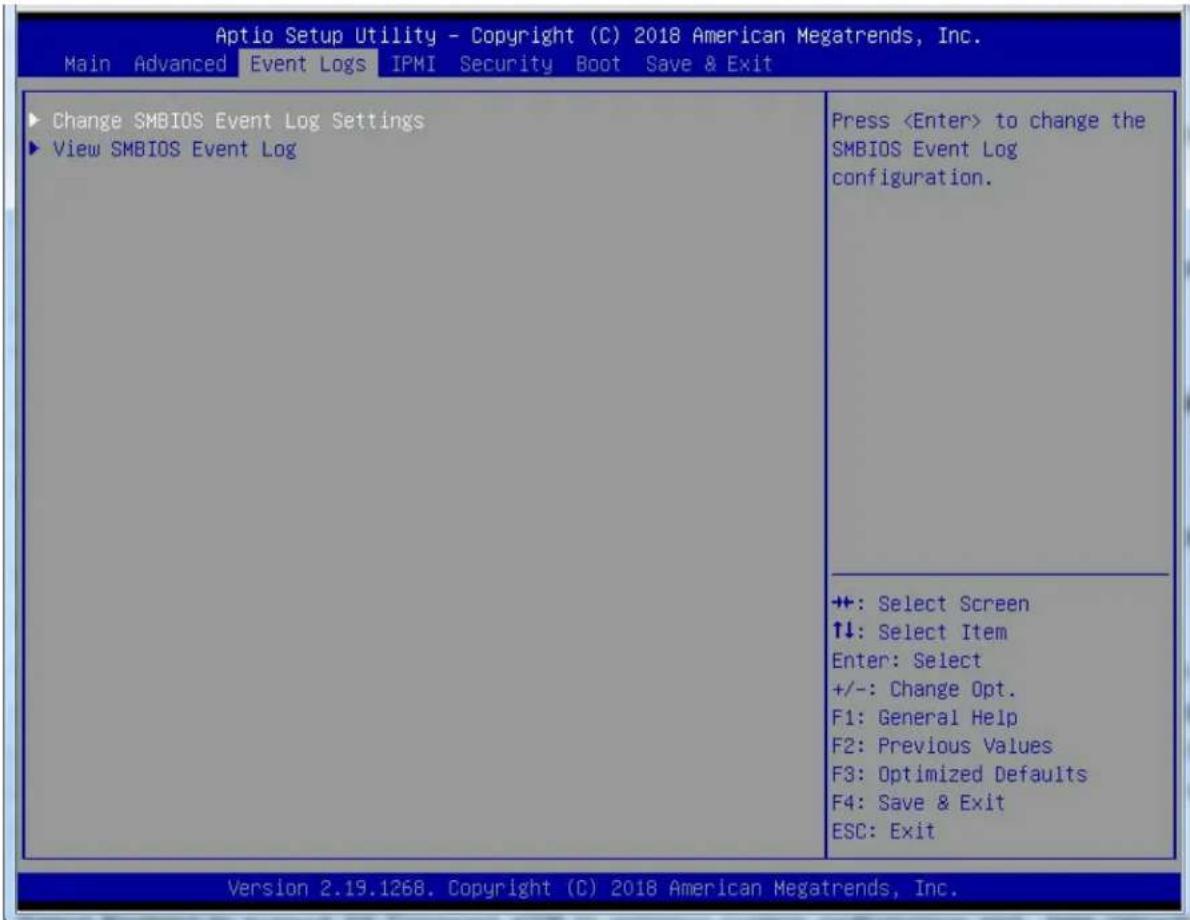
text_image
Aptio Setup Utility - Copyright (C) 2018 American Megatrends, Inc. Main Advanced Event Logs IPMI Security Boot Save & Exit ► Change SMBIOS Event Log Settings ► View SMBIOS Event Log Press▶Change SMBIOS Event Log Settings
Enabling/Disabling Options
SMBIOS Event Log
Select Enabled to enable SMBIOS (System Management BIOS) Event Logging during system boot. The options are Enabled and Disabled.
Erasing Settings
Erase Event Log (Available when the item: SMBIOS Event Log is set to Enabled)
Select Enabled to erase all error events in the SMBIOS (System Management BIOS) log before an event logging is initialized at bootup. The options are No, Yes, Next Reset, and Yes, Every Reset.
When Log is Full (Available when the item: SMBIOS Event Log is set to Enabled)
Select Erase Immediately to immediately erase all errors in the SMBIOS event log when the event log is full. Select Do Nothing for the system to do nothing when the SMBIOS event log is full. The options are Do Nothing, and Erase Immediately.
SMBIOS Event Log Standard Settings
Log System Boot Event (Available when the item: SMBIOS Event Log is set to Enabled)
Select Enabled to log system boot events. The options are Enabled and Disabled.
MECI (Multiple Event Count Increment) (Available when the item: SMBIOS Event Log is set to Enabled)
Enter the increment value for the multiple event counter. Enter a number between 1 to 255. The default setting is 1.
METW (Multiple Event Count Time Window) (Available when the item: SMBIOS Event Log is Enabled)
Use this feature to specify how long (in minutes) the multiple event counter should wait before generating a new event log. Enter a number between 0 to 99. The default setting is 60.
Note: Please reboot the system for the changes to take effect.
▶View SMBIOS Event Log
This item allows the user to view the event in the system event log. Select this feature and press
Date/Time/Error Code/Severity
6.5 IPMI
Use this feature to configure Intelligent Platform Management Interface (IPMI) settings.
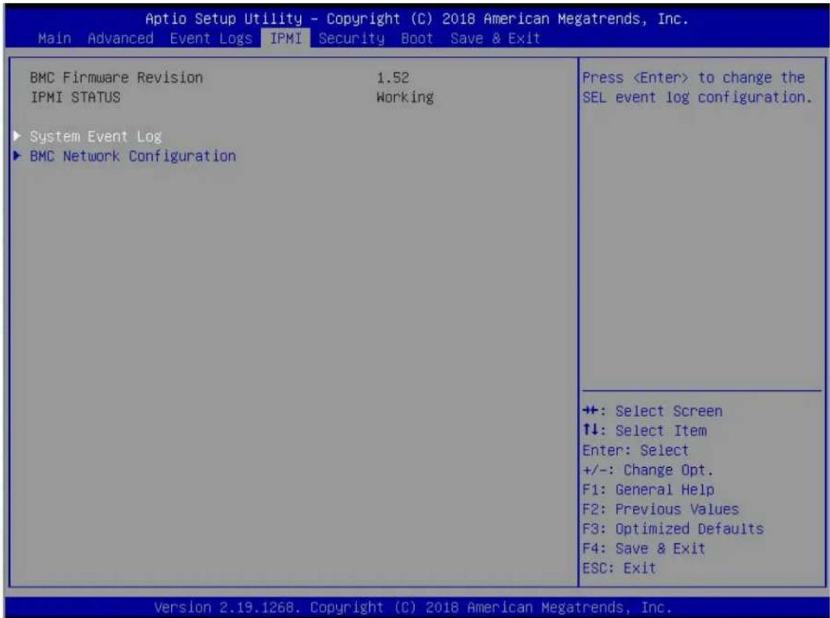
text_image
Aptio Setup Utility - Copyright (C) 2018 American Megatrends, Inc. Main Advanced Event Logs IPMI Security Boot Save & Exit BMC Firmware Revision 1.52 IPMI STATUS Working ► System Event Log ► BMC Network Configuration PressWhen you select this submenu and press the
- BMC Firmware Revision: This feature indicates the firmware revision of the BMC (Baseboard Management Controller) used in your system.
- IPMI Status: This feature indicates IPMI status of your system.
▶System Event Log
Enabling/Disabling Options
SEL Components
Select Enabled for all system event logging at bootup. The options are Enabled and Disabled.
Erasing Settings
Erase SEL (Available when the item: SEL Components is set to Enabled)
Select Yes, On next reset to erase all system event logs upon next system reboot. Select Yes, On every reset to erase all system event logs upon each system reboot. Select No to keep all system event logs after each system reboot. The options are No, Yes, On next reset, and Yes, On every reset.
When SEL is Full (Available when the item: SEL Components is set to Enabled)
This feature allows the user to specify what the BIOS should do when the system event log is full. Select Erase Immediately to erase all events in the log when the system event log is full. The options are Do Nothing and Erase Immediately.
▶BMC Network Configuration
Update IPMI LAN Configuration
Select Yes for the BIOS to implement all IP/MAC address changes at the next system boot. The options are No and Yes. The following items will be displayed:
- IPMI LAN Selection: This feature displays the IPMI LAN setting. The default setting is Failover.
- IPMI Network Link Status: This item displays the IPMI Network Link status. The default setting is Dedicated LAN.
- Configuration Address Source: This feature displays the source of the current IPMI LAN address. The default setting is DHCP (Dynamic Host Configuration Protocol).
- Station IP Address: This feature displays the Station IP address for this computer. This should be in decimal and in dotted quad form (i.e., 192.168.10.253).
- Subnet Mask: This feature displays the sub-network that this computer belongs to. The value of each three-digit number separated by dots should not exceed 255.
- Station MAC Address: This feature displays the Station MAC address for this computer. Mac addresses are 6 two-digit hexadecimal numbers.
- Gateway IP Address: This feature displays the Gateway IP address for this computer. This should be in decimal and in dotted quad form (i.e., 192.168.10.253).
- VLAN: Select Enabled to enable IPMI VLAN support. The options are Enabled and Disabled.
*If the item "Update IPMI LAN Configuration" is set to Yes, the following items will display:
IPMI LAN Selection
Use this feature to select the type of the IPMI LAN. The options are Dedicated, Shared, and Failover.
IPMI Network Link Status
This item displays the IPMI Network Link status. The default setting is Dedicated LAN.
Configuration Address Source
Use this feature to select the IP address source for this computer. If Static is selected, you will need to know the IP address of this computer and enter it to the system manually in the field. If DHCP is selected, AMI BIOS will search for a DHCP (Dynamic Host Configuration Protocol) server attached to the network and request the next available IP address for this computer. The options are DHCP and Static.
*When the option: Static is selected, the following features will be available for configuration:
- Station IP Address
- Subnet Mask
• Station MAC Address
VLAN
Select Enabled for IPMI VLAN support. The options are Disabled and Enabled.
*If the item above "VLAN" is set to Enabled, the following item will be available:
VLAN ID
Use this feature to set the VLAN ID number. The default setting is 0.
Configure IPV6 Support
IPV6 Support
Select Enabled for IPV6 support. The options are Enabled and Disabled.
Configuration Address Source
Use this feature to select the IP address source for this computer. If Static is selected, you will need to know the IP address of this computer and enter it to the system manually in the field. If DHCP is selected, AMI BIOS will search for a DHCP (Dynamic Host Configuration Protocol) server attached to the network and request the next available IP address for this computer. The options are DHCP and Static. When the option: Static is selected, the following features will be displayed:
• Station IPV6 Address
- Prefix Length
• IPV6 Router1 IP Address
6.6 Security Settings
This menu allows the user to configure the following security settings for the system.
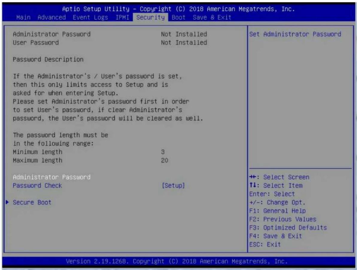
text_image
Aptio Setup Utility - Copyright (C) 2018 American Megatrends, Inc. Main Advanced Event Logs IPMI Security Boot Save & Exit Administrator Password Not Installed User Password Not Installed Password Description If the Administrator's / User's password is set, then this only limits access to Setup and is asked for when entering Setup. Please set Administrator's password first in order to set User's password, if clear Administrator's password, the User's password will be cleared as well. The password length must be in the following range: Minimum length 3 Maximum length 20 Administrator Password Password Check [Setup] ▶ Secure Boot Set Administrator Password ++: Select Screen ↑↓: Select Item Enter: Select +/-: Change Opt. F1: General Help F2: Previous Values F3: Optimized Defaults F4: Save & Exit ESC: Exit Version 2.19.1268. Copyright (C) 2018 American Megatrends, Inc.Administrator Password
Use this feature to set the administrator password which is required to enter the BIOS setup utility. The length of the password should be from 3 characters to 20 characters long.
User Password
Use this feature to set the user password which is required to enter the BIOS setup utility. The length of the password should be from 3 characters to 20 characters long.
Password Check
Select Setup for the system to check for a password at Setup. Select Always for the system to check for a password at bootup or upon entering the BIOS Setup utility. The options are Setup and Always.
▶Secure Boot
When you select this submenu and press the
- System Mode
- Secure Boot
- Vendor Keys
Secure Boot
If this feature is set to Enabled, Secure Boot will be activated when a Platform Key (PK) is entered. A Platform Key is a security key used to manage the security settings of the platform firmware used in your system. The options are Enabled and Disabled.
Secure Boot Mode
Use this feature to select the desired secure boot mode for the system. The options are Standard and Custom.
CSM Support
Select Enabled to enable Compatibility Service Module (CMS) which will support Legacy BIOS through UEFI to enhance system performance. The options are Enabled and Disabled
▶Key Management
Provision Factory Default Keys
Select Enabled to install all manufacturer default keys to configure the following system security settings. The options are Enabled and Disabled.
▶Enroll All Factor Default Keys
Select Yes to install all manufacturer defaults to configure the following system security settings. The options are Yes and No.
▶Enroll EFI Image
Select this item and press
▶Save All Secure Boot Variables
This feature allows the user to set and save the secure boot key variables specified by the user.
▶Platform Key (PK)
This feature allows the user to enter and configure a set of values to be used as a platform firmware key for the system. This set of values also indicate the size, the keys numbers, and the key source of the Platform Key. The options are Save to File, Set New, and Erase.
▶Key Exchange Keys
This feature allows the user to enter and configure a set of values to be used as a Key-Exchange-Keys for the system. This set of values also indicate the size, the keys numbers, and the key source of the Key-Exchange-Keys. The options are Save to File, Set New, and Erase.
▶Authorized Signatures
This feature allows the user to enter and configure a set of values to be used as Authorized Signatures for the system. These values also indicate the size, the keys numbers, and the key source of the Authorized Signatures. The options are Set New and Append.
Secure Boot Variable/Size/Key#/Key Sources The options are Save to File, Set New, and Erase.
▶Forbidden Signatures
This feature allows the user to enter and configure a set of values to be used as Forbidden Signatures for the system. These values also indicate the size, the keys numbers, and the key source of the Forbidden Signatures. The options are Save to File, Set New, and Erase.
▶Authorized TimeStamps
This feature allows the user to set and save the timestamps for Authorized Signatures to indicate when these signatures were entered into the system. The options are Save to File, Set New, and Erase.
▶OsRecovery Signatures
This feature allows the user to set and save the Authorized Signatures used for OS recovery. The options are Save to File, Set New, and Erase.
6.7 Boot Settings
Use this feature to configure Boot Settings:

text_image
Aptio Setup Utility - Copyright (C) 2018 American Megatrends, Inc. Main Advanced Event Logs IPMI Security Boot Save & Exit Boot Configuration Boot mode select [DUAL] LEGACY to EFI support [Disabled] FIXED BOOT ORDER Priorities Boot Option #1 [Hard Disk] Boot Option #2 [CD/DVD] Boot Option #3 [USB Hard Disk] Boot Option #4 [USB CD/DVD] Boot Option #5 [USB Key] Boot Option #6 [USB Floppy] Boot Option #7 [USB Lan] Boot Option #8 [Network] Boot Option #9 [UEFI Hard Disk] Boot Option #10 [UEFI CD/DVD] Boot Option #11 [UEFI USB Hard Disk] Boot Option #12 [UEFI USB CD/DVD] Boot Option #13 [UEFI USB Key] Boot Option #14 [UEFI USB Floppy] Boot Option #15 [UEFI USB Lan] Boot Option #16 [UEFI Network] Boot Option #17 [UEFI AP:UEFI: Bui...] ► Delete Boot Option Select boot mode LEGACY/UEFI ++: Select Screen ↑↓: Select Item Enter: Select +/-: Change Opt. F1: General Help F2: Previous Values F3: Optimized Defaults F4: Save & Exit ESC: Exit Version 2.19.1268. Copyright (C) 2018 American Megatrends, Inc.Boot Mode Select
Use this feature to select the type of devices to be used for system boot. The options are Legacy, UEFI (Unified Extensible Firmware Interface), and Dual.
Legacy to EFI Support
Select Enabled for the system to boot from an EFI OS when the Legacy OS fails. The options are Enabled and Disabled.
Fixed Boot Order Priorities
This feature prioritizes the order of a bootable device from which the system will boot. Press
*When the item above - "Boot Mode Select" is set to Dual (default), the following items will be displayed for configuration:
- Boot Option #1 - Boot Option #17
*When the item above - "Boot Mode Select" is set to Legacy, the following items will be display for configuration:
- Boot Option #1 - Boot Option #8
*When the item above - "Boot Mode Select" is set to UEFI, the following items will be display for configuration:
- Boot Option #1 - Boot Option #9
Add New Boot Option
This feature allows the user to add a new boot option to the boot priority features for your system.
Add Boot Option
Use this feature to specify the name for the new boot option.
Path for Boot Option
Use this feature to enter the path for the new boot option in the format fsx:\path\filename.efi.
Boot Option File Path
Use this feature to specify the file path for the new boot option.
Create
After the name and the file path for the boot option are set, press
▶ Add New Driver Option
Use this feature to select a new driver to add to the boot priority list.
Add Driver Option
Use this feature to specify the name of the driver that the new boot option is added to.
Path for Driver Option
Use this feature to specify the path to the driver that the new boot option is added to.
Driver Option File Path
Use this feature to specify the file path of the driver that the new boot option is added to.
Create
After the driver option name and the file path are set, press
▶ Delete Boot Option
Use this feature to select a boot device to delete from the boot priority list.
Delete Boot Option
Use this feature to remove an EFI boot option from the boot priority list.
▶ Delete Driver Option
Use this item to select a boot driver to delete from the boot priority list.
Delete Drive Option
Select the target boot driver to delete from the boot priority list.
▶ Hard Disk Drive BBS Priorities
- Boot Option #1 - #5
▶ Network Drive BBS Priorities
- Boot Option #1
▶USB Key Drive BBS Priorities
- Boot Option #1
▶ UEFI Hard Disk Drive BBS Priorities
- Boot Option #1
▶ UEFI USB Key Drive BBS Priorities
- Boot Option #1
▶ UEFI Application Boot Priorities
- Boot Option #1
6.8 Save & Exit
Select the Save & Exit tab from the BIOS setup screen to configure the settings below.

text_image
Aptio Setup Utility - Copyright (C) 2018 American Megatrends, Inc. Main Advanced Event Logs IPMI Security Boot Save & Exit Save Options Discard Changes and Exit Save Changes and Reset Save Changes Discard Changes Default Options Restore Optimized Defaults Save as User Defaults Restore User Defaults Boot Override UEFI: Built-in EFI Shell Save Changes done so far to any of the setup options. ++: Select Screen ↑↓: Select Item Enter: Select +/-: Change Opt. F1: General Help F2: Previous Values F3: Optimized Defaults F4: Save & Exit ESC: Exit Version 2.19.1268. Copyright (C) 2018 American Megatrends, Inc.Save Options
Discard Changes and Exit
Select this option to quit the BIOS setup without making any permanent changes to the system configuration and reboot the computer. Select Discard Changes and Exit from the Exit menu and press
Save Changes and Reset
When you have completed the system configuration changes, select this option to leave the BIOS setup utility and reboot the computer for the new system configuration parameters to take effect. Select Save Changes and Exit from the Exit menu and press
Save Changes
When you have completed the system configuration changes, select this option to save all changes made. This will not reset (reboot) the system.
Discard Changes
Select this option and press
Default Options
Restore Optimized Defaults
To set this feature, select Restore Defaults from the Exit menu and press
Save As User Defaults
To set this feature, select Save as User Defaults from the Exit menu and press
To set this feature, select Restore User Defaults from the Exit menu and press
Boot Override
This feature allows the user to override the Boot priorities sequence in the Boot menu, and immediately boot the system with a device specified by the user instead of the one specified in the boot list. This is a one-time override.
Appendix A
BIOS Error Codes
A-1 BIOS Error Beep (POST) Codes
During the POST (Power-On Self-Test) routines, which are performed each time the system is powered on, errors may occur.
Non-fatal errors are those which, in most cases, allow the system to continue the boot-up process. The error messages normally appear on the screen.
Fatal errors are those which will not allow the system to continue the boot-up procedure. If a fatal error occurs, you should consult with your system manufacturer for possible repairs.
These fatal errors are usually communicated through a series of audible beeps.
| BIOS Error Beep (POST) Codes | ||
| Beep Code Error | Message Description | |
| 1 short Refresh Circuits have been reset (Ready to power up) | ||
| 5 short, 1 long Memory error No memory detected in system | ||
| 5 long, 2 short Display memory read/write error Video adapter missing or with faulty memory | ||
| 1 long continuous System OH System overheat condition | ||
A-2 Additional BIOS POST Codes
The AMI BIOS supplies additional checkpoint codes, which are documented online at http://www.supermicro.com/support/manuals/ ("AMI BIOS POST Codes User's Guide").
When BIOS performs the Power On Self Test, it writes checkpoint codes to I/O port 0080h. If the computer cannot complete the boot process, a diagnostic card can be attached to the computer to read I/O port 0080h (Supermicro p/n AOC-LPC80-20).
For information on AMI updates, please refer to http://www.ami.com/products/.
Appendix B
Standardized Warning Statements for AC Systems
B.1 About Standardized Warning Statements
The following statements are industry standard warnings, provided to warn the user of situations which have the potential for bodily injury. Should you have questions or experience difficulty, contact Supermicro's Technical Support department for assistance. Only certified technicians should attempt to install or configure components.
Read this appendix in its entirety before installing or configuring components in the Supermicro chassis.
These warnings may also be found on our website at http://www.supermicro.com/about/policies/safety_information.cfm.
Warning Definition

Warning! This warning symbol means danger. You are in a situation that could cause bodily injury. Before you work on any equipment, be aware of the hazards involved with electrical circuitry and be familiar with standard practices for preventing accidents.
警告の定義
この警告サインは危険を意味します。
Installation Instructions

Warning! Read the installation instructions before connecting the system to the power source.
設置手順書
Warning! This product relies on the building's installation for short-circuit (overcurrent) protection. Ensure that the protective device is rated not greater than: 250 V, 20 A.
サーキット・ブレーカー
Power Disconnection Warning

Warning! The system must be disconnected from all sources of power and the power cord removed from the power supply module(s) before accessing the chassis interior to install or remove system components.
電源切断の警告
Equipment Installation

Warning! Only trained and qualified personnel should be allowed to install, replace, or service this equipment.
機器の設置
Warning! This unit is intended for installation in restricted access areas. A restricted access area can be accessed only through the use of a special tool, lock and key, or other means of security. (This warning does not apply to workstations).
アクセス制限区域
Warning! There is the danger of explosion if the battery is replaced incorrectly. Replace the battery only with the same or equivalent type recommended by the manufacturer. Dispose of used batteries according to the manufacturer's instructions
電池の取り扱い
Redundant Power Supplies

Warning! This unit might have more than one power supply connection. All connections must be removed to de-energize the unit.
冗長電源装置
Warning! Hazardous voltage or energy is present on the backplane when the system is operating. Use caution when servicing.
バックプレーンの電圧
Comply with Local and National Electrical Codes

Warning! Installation of the equipment must comply with local and national electrical codes.
地方および国の電気規格に準拠
Warning! Ultimate disposal of this product should be handled according to all national laws and regulations.
製品の廃棄
Warning! Hazardous moving parts. Keep away from moving fan blades. The fans might still be turning when you remove the fan assembly from the chassis. Keep fingers, screwdrivers, and other objects away from the openings in the fan assembly's housing.
ファン・ホットスワップの警告
Power Cable and AC Adapter

Warning! When installing the product, use the provided or designated connection cables, power cables and AC adaptors. Using any other cables and adaptors could cause a malfunction or a fire. Electrical Appliance and Material Safety Law prohibits the use of UL or CSA-certified cables (that have UL/CSA shown on the cord) for any other electrical devices than products designated by Supermicro only.
電源コードとACアダプター
System Specifications
Processors
Dual 81xx/61xx/51xx/41xx/31xx and 82xx/62xx/52xx/42xx/32xx processor in an Socket P0 type sockets for each node. Note: Please refer to the motherboard specifications pages on our website for updates to supported processors.
Chipset
C621 chipset
BIOS
32 MB SPI AMI BIOS® SM Flash UEFI BIOS
Memory
Integrated memory controller embedded in the processor supports up to 1.5 TB of 3DS Load Reduced DIMM (3DS LRDIMM), Load Reduced DIMM (LRDIMM), 3DS Registered DIMM (3DS RDIMM), Registered DIMM (RDIMM), and NVDIMM DDR4 (288-pin) ECC memory of 2933/2666/2400/2133 MHz in 12 slots Note: See the memory section in Chapter 3 for details and our website for updates to supported memory.
SATA Controller
On-chip (C621) controller
Drive Bays
Each node has two 2.5" SATA3/NVMe internal drives, with an optional kit that adds an additional two (2) internal SATA3/NVMe drives for a total of four (4) drives.
PCI Expansion Slots
The X11DPFF-SNR motherboard has the following expansion slots:
One PCI-E 3.0 x16 slot supported by CPU 1 (JPCIE4)
One PCI-E 3.0 x8 slot supported by CPU 1 (Slot2)
One PCI-E 3.0 x16 Super I/O Module slot supported by CPU 1 (SIOM)
Two NVMe for PCI-E high-speed storage devices with option for two more drives, supported by CPU2 (PN-NVMe 0/1/2/3)
One Riser card header for SDD1 devices
Motherboard
Eight X11DPFF-SNR motherboards, proprietary form factor (18.73" (L) x 8.54" (W) (475.74 mm x 216.92 mm))
Chassis
F418IF3-R2K20BP; 4U Rackmount,(WxHxD) 17.63 x 6.96 x 29 in. (448 x 177 x 737 mm)
Power
Four 2000 or 2200 Watt redundant power supplies
System Cooling
Up to eight 8-cm hot-swappable cooling fans mounted in the rear chassis
Power Supply
Model: PWS-2K20A-1R or PWS-2K04A-1R
AC Input Voltages: 100-240 VAC
Rated Input Current: 15-12A (100-127V) to 8.5-7A (200-240V)
Rated Input Frequency: 50-60 Hz
Rated Output Power: 2000W/2200W
Rated Output Voltages: 83A (+12V 100-127Vac), 100A (+12V 200-240Vac), 0-4A (+5Vsb)
Operating Environment
Operating Temperature: 10° to 35° C (50° to 95° F)
Non-operating Temperature: -40° to 60° C (-40° to 140° F)
Operating Relative Humidity: 8% to 90% (non-condensing)
Non-operating Relative Humidity: 5% to 95% (non-condensing)
Regulatory Compliance
Electromagnetic Emissions: FCC Class A, EN 55032 Class A, EN 61000-3-2/3-3, CISPR 32 Class A
Electromagnetic Immunity: EN 55024/CISPR 24, (EN 61000-4-2, EN 61000-4-3, EN 61000-4-4, EN 61000-4-5, EN 61000-4-6, EN 61000-4-8, EN 61000-4-11), CNS14336-1, CNS13438, GB4943.1-2011, GB9254-2008(Class A) and GB17625.1-2012
Safety: CSA/EN/IEC/UL 60950-1 Compliant, UL or CSA Listed (USA and Canada), CE Marking (Europe)
Other: VCCI-CISPR 32 and AS/NZS CISPR 32
Environmental: Directive 2011/65/EU and Delegated Directive (EU) 2015/863 and Directive 2012/19/EU
Perchlorate Warning
California Best Management Practices Regulations for Perchlorate Materials: This Perchlorate warning applies only to products containing CR (Manganese Dioxide) Lithium coin cells. "Perchlorate Material-special handling may apply. See www.dtsc.ca.gov/hazardouswaste/perchlorate"
Appendix D
UEFI BIOS Recovery
Warning: Do not upgrade the BIOS unless your system has a BIOS-related issue. Flashing the wrong BIOS can cause irreparable damage to the system. In no event shall Supermicro be liable for direct, indirect, special, incidental, or consequential damages arising from a BIOS update. If you need to update the BIOS, do not shut down or reset the system while the BIOS is updating to avoid possible boot failure.
D.1 Overview
The Unified Extensible Firmware Interface (UEFI) provides a software-based interface between the operating system and the platform firmware in the pre-boot environment. The UEFI specification supports an architecture-independent mechanism that will allow the UEFI OS loader stored in an add-on card to boot the system. The UEFI offers clean, hands-off management to a computer during system boot.
D.2 Recovering the UEFI BIOS Image
A UEFI BIOS flash chip consists of a recovery BIOS block and a main BIOS block (a main BIOS image). The recovery block contains critical BIOS codes, including memory detection and recovery codes for the user to flash a healthy BIOS image if the original main BIOS image is corrupted. When the system power is turned on, the recovery block codes execute first. Once this process is complete, the main BIOS code will continue with system initialization and the remaining POST (Power-On Self-Test) routines.
Note 1: Follow the BIOS recovery instructions below for BIOS recovery when the main BIOS block crashes.
Note 2: When the BIOS recovery block crashes, you will need to follow the procedures to make a Returned Merchandise Authorization (RMA) request. (For a RMA request, please see section 3.5 for more information). Also, you may use the Supermicro Update Manager (SUM) Out-of-Band (OOB) (https://www.supermicro.com.tw/products/nfo/SMS_SUM.cfm) to reflash the BIOS.
D.3 Recovering the Main BIOS Block with a USB Device
This feature allows the user to recover the main BIOS image using a USB-attached device without additional utilities used. A USB flash device such as a USB Flash Drive, or a USB CD/DVD ROM/RW device can be used for this purpose. However, a USB Hard Disk drive cannot be used for BIOS recovery at this time.
The file system supported by the recovery block is FAT (including FAT12, FAT16, and FAT32) which is installed on a bootable or non-bootable USB-attached device. However, the BIOS might need several minutes to locate the SUPER.ROM file if the media size becomes too large due to the huge volumes of folders and files stored in the device.
To perform UEFI BIOS recovery using a USB-attached device, follow the instructions below.
- Using a different machine, copy the "Super.ROM" binary image file into the Root "\" directory of a USB device or a writable CD/DVD.
Note: If you cannot locate the "Super.ROM" file in your drive disk, visit our website at www.supermicro.com to download the BIOS package. Extract the BIOS binary image into a USB flash device and rename it "Super.ROM" for the BIOS recovery use.
- Insert the USB device that contains the new BIOS image ("Super.ROM") into your USB drive and reset the system when the following screen appears.

text_image
PEI--Could Not Find Recovery Image... BMC IP:10.132.160.92 07- After locating the healthy BIOS binary image, the system will enter the BIOS Recovery menu as shown below.

text_image
Auto Setup Utility - Copyright (C) 2017 American Megatrends, Inc. Recovery WARNING! System Firmware is being updated. Keyboard is locked. DO NOT TURN THE POWER OFF till Once firmware update is completed press any key to reboot the system Program new data write new boot block... 17% +: Select Screen T4: Select Item Enter Select +/- Change Dot. F1: General Help F2: Previous Values F3: Optimized Defaults F4: Save & Exit ESC: Exit Version 0.19.1566. Copyright (C) 2017 American Megatrends, Inc.Note: At this point, you may decide if you want to start the BIOS recovery. If you decide to proceed with BIOS recovery, follow the procedures below.
- When the screen as shown above displays, use the arrow keys to select the item "Proceed with flash update" and press the
key. You will see the BIOS recovery progress as shown in the screen below.
Note: Do not interrupt the BIOS flashing process until it has completed.
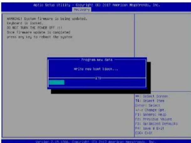
text_image
Notio Setup Utility - Copyright (C) 2017 American Megatrends, Inc. Recovery WARNING! System firmware is being updated. Keyboard is locked. DO NOT TURN THE POWER OFF IT Dice firmware update is completed press any key to reboot the system Program new data write new boot block... 17% +: Select Screen T4: Select item Enter: Select +/-: Change Opt. F1: General help F2: Previous Values F3: Optimized Defaults F4: Save & Exit ESC: Exit Version 2.15.1266. Copyright (C) 2017 American Megatrends, Inc.- After the BIOS recovery process is complete, press any key to reboot the system.

text_image
Rotio Setup Utility - Copyright ICT 2017 American Megatrends, Inc. Recovery WARNING! System firmware is being updated. Keyboard is locked. DO NOT TURN THE POWER OFF !!! Once firmware update is completed press any key to reboot the system Flash update Flash update completed. Press any key to reset the system +: Select Screen T4: Select Item Enter: Select +/-: Change Opt F1: General Help F2: Previous Values F3: Optimized Defaults F4: Save & Exit ESC: Exit Version 0.19.1056. Copyright © 2017 American Megatrends, Inc.-
Using a different system, extract the BIOS package into a USB flash drive.
-
Press
continuously during system boot to enter the BIOS Setup utility. From the top of the tool bar, select Boot to enter the submenu. From the submenu list, select Boot Option #1 as shown below. Then, set Boot Option #1 to [UEFI AP:UEFI: Built-in EFI Shell]. Pressto save the settings and exit the BIOS Setup utility.

text_image
Boot Configuration Boot mode select [DUAL] LESACY to EFI support [Disabled] FIXED BOOT ORDER PRIORities Boot Option #1 [DEFI #P:DEFI: Bui...] Boot Option #2 [CD/DVD] Boot Option #3 [USB Hard Disk] Boot Option #4 [USB CD/DVD] Boot Option #5 [USB Key:BandDisk] Boot Option #6 [USB Floppy] Boot Option #7 [USB Lan] Boot Option #8 [Network:IDA (E SI...)] Boot Option #9 [DEFI Hard Disk] Boot Option #10 [DEFI CD/DVD] Boot Option #11 [DEFI USB Hard Disk] Boot Option #12 [DEFI USB CD/DVD] Boot Option #13 [DEFI USB Key:EFI...] Boot Option #14 [DEFI USB Floppy] Boot Option #15 [DEFI USB Lan] Boot Option #16 [DEFI Network] Boot Option #17 [Hard Disk] Add New Boot Option Sets the system boot order +: Select Screen T1: Select Item Enter: Select +/+ Change Opt. F1: General Help F2: Previous Values F3: Optimized Defaults F4: Save & Exit ESC: Exit Version 2.19.1266, Copyright IX 2017 American Megatrends, Inc.- When the UEFI Shell prompt appears, type fs# to change the device directory path. Go to the directory that contains the BIOS package you extracted earlier from Step 6. Enter flash.nsh BIOSname.### at the prompt to start the BIOS update process.
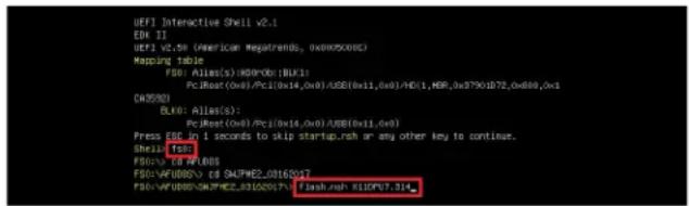
text_image
UIFI Interactive Shell v2.1 EIX 11 UIFI v2.5e (American MegaTrends, 0x0005000) Mapping Table F86: Alias(s):MD00b(BLK): PcJRoot(0x6)/PcC1(0x14,0x8)/AUSE(0x11,0x8)/HDI(1,HDR_0x97901B72,0x888,0x1 DW5920 BLK: Alias(s): PcJRoot(0x6)/PcC1(0x14,0x8)/AUSE(0x11,0x8) Press ESE in 1 seconds to skip startup.rash or any other key to continue. Shell: F86 F86: /CD F86/085 F86:WFURBSO CD SHAPHE2_03162017 F86:WFURBSO SHAPHE2_03162017 Flash.rash R110P67.314Note: Do not interrupt this process until the BIOS flashing is complete.
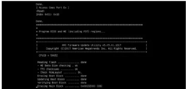
text_image
[ Access Ows Fort Ex ]Firmware Update Utility v5-49.01.1017
Copyright (C)2017 American Regatrends Inc. All Rights Reserved. CPUID = 50652 Reading flash ....... done - ME Data Size checking .. ok - FFS checksums ....... OK - Check ReLayout ....... BL Erasing Boot Block ....... done Updating Boot Block ....... done Verifying Boot Block ....... done _Verifying Main Block ....... 0x00132X00 [0x]- The screen above indicates that the BIOS update process is complete. When you see the screen above, unplug the AC power cable from the power supply, clear CMOS, and plug the AC power cable in the power supply again to power on the system.

text_image
Verifying HCB Block ......... done - Update success for FDB - Update success for IE, - - Successful update Recovery Leader to OPRx!! - Successful update F3811- - Successful update F1PRX!! - Successful update F05, D01 and I2B21!! - Successful update FLOB and I00X!! - ML Entire Image update success !!! WARNING : System next power-off to have the changes take effect! Moving FDS:AFU00S\SAFPHZE_03162017\t4xt\x4.efi -> FDS:AFU00S\SAFPHZE_03162017\t4x.f6.smc - [ok] Moving FDS:AFU00S\SAFPHZE_03162017\t4xfuf\x4.efi -> FDS:AFU00S\SAFPHZE_03162017\t4x.f6.smc - [ok] ********************************************************************** * - Please ignore this 'Shell cannot read from file - device tryer' + warning message due to it does not impact flashing process. * ********************************************************************** Deleting ' 1.00' (File) Delete successful. FDS:>- Press
continuously to enter the BIOS Setup utility. - Press
to load the default settings. - After loading the default settings, press
to save the settings and exit the BIOS Setup utility.
Appendix E
BSMI Safety Warnings
限用物質含有情況標示聲明書
Declaration of the Presence Condition of the Restricted Substances Marking
限制物質含有情況標示聲明書
Declaration of the Presence Condition of the Restricted Substances Marking
| 試者名稱:伺服器/ServerEquipment nam | ||||||
| 型號(型號):F418-22Type designation (Type)系列型號:F418-X11,SYS-F619P2-FT,SYS-F619P3-FT,SYS-F619P2-FT-RD-TS29T,SYS-F619P2-FT-IT1-TS29T,SYS-F619P2-FT-IT2-TS29T,SYS-F619P2-FT-IT3-TS29T,SYS-F619P2-FT-IT4-TS29T,SYS-F619P2-FT-IT5-TS29T,SYS-F619P2-FT-IT6-TS29T,SYS-F619P2-FT-IT7-TS29T,SYS-F619P2-FT-IT8-TS29T,SYS-F619P2-FT-IT9-TS29T,SYS-F619P2-FT-IT10-TS29T | ||||||
| 單元Unit | 現*物質及其化學符號Restricted substances and its chemical symbols | |||||
| 鉛Lead(Pb) | 長Mercury(Hg) | 銻Cadmium(Cd) | 六億錦Hexavalentchromium( Cr^+6 ) | 多溴聯苯Polybrominatedbiphenyls(PBB) | 多溴二苯酸Polybrominateddiphenyl ethers(PBDE) | |
| 機殼(Chassis) | ○ | ○ | ○ | ○ | ○ | ○ |
| 機殼風扇(Chassis Fan) | - | ○ | ○ | ○ | ○ | ○ |
| 線材(Cable) | ○ | ○ | ○ | ○ | ○ | ○ |
| 主機板(Motherboard) | - | ○ | ○ | ○ | ○ | ○ |
| 電源供應器(Power Supply) | - | ○ | ○ | ○ | ○ | ○ |
| 硬碟(Hard Disk) | - | ○ | ○ | ○ | ○ | ○ |
| 電源背板(PDB) | - | ○ | ○ | ○ | ○ | ○ |
| 附加卡(Add-on Card) | - | ○ | ○ | ○ | ○ | ○ |
| 備考1.“超出0.1 wt%”及“超出0.01 wt%”係指現*物質之百分比含量超出百分比含量基準值。Note 1:“Exceeding 0.1 wt %” and “exceeding 0.01 wt %” indicate that the percentage content of the restricted substance exceeds thereference percentage value of presence condition.備考2.“○”係指該項現*物質之百分比含量大超出百分比含量基準值。Note 2:“○” indicates that the percentage content of the restricted substance does not exceed the percentage of reference value of presence.備考3.“-”係指該項現*物質言排除項目。Note 3:The “-” indicates that the restricted substance corresponds to the exemption. | ||||||

警告使用者:
CPU-Based RAID for NVMe
Intel® Virtual RAID on CPU (Intel VROC) is an enterprise RAID solution for NVMe SSDs directly attached to Intel Xeon Scalable processors. Intel Volume Management Device (VMD) is an integrated controller inside the CPU PCI-E root complex.
- A single processor supports up to 12 NVMe SSDs and up to 6 RAID arrays.
- A dual processor system supports up to 24 NVMe SSDs and 12 RAID arrays.
Strip sizes are 4K, 8K, 16K, 32K, 64K, 128K.
Requirements and Restrictions
- Intel VROC is only available when the system is configured for UEFI boot mode.
- To enable the mdadm command and support for RSTe, install the patch from
- Linux: https://downloadcenter.intel.com/download/28158/Intel-Virtual-RAID-on-CPU-Intel-VROC-and-Intel-Rapid-Storage-Technology-enterprise-Intel-RSTe-Driver-for-Linux-
- Windows: https://downloadcenter.intel.com/download/28108/Intel-Virtual-RAID-on-CPU-Intel-VROC-and-Intel-Rapid-Storage-Technology-enterprise-Intel-RSTe-Driver-for-Windows-
- To enable Intel VROC, a hardware key must be inserted on the motherboard, and the appropriate processor's Virtual Management Devices must be enabled in the BIOS setup.
- It is possible to enable Intel VROC without a hardware key installed, but only RAID0 will be enabled.
- Intel VROC is not compatible with secure boot. This feature must be disabled.
- When creating bootable OS RAID1 devices, you must have both devices on the same CPU, and a VMD on that CPU.
- Spanning drives when creating RAID devices is not recommended to due to performance issues, even though it is supported.
Supported SSDs and Operating Systems
To see the latest support information: https://www.intel.com/content/www/us/en/support/articles/000030310/memory-and-storage/ssd-software.html
Additional Information
Additional information is available on the product page for the Supermicro add-on card and the linked manuals.
www.supermicro.com/products/accessories/addon/AOC-VROCxxxMOD.cfm
F.1 Hardware Key
The Intel VROC hardware key is a license key that detects the Intel VROC SKU and activates the function accordingly. The key must be plugged into the Supermicro motherboard (connector JRK1). The key options are:
| Intel® VROC Keys | |||
| VROC Package Description Part Number Intel MM Number | |||
| Standard | RAID 0, 1, 10Supports 3rd party SSDs | AOC-VROCSTNMOD 95 | 1605 |
| Premium | RAID 0, 1, 5, 10Supports 3rd party SSDs | AOC-VROCPREMOD 95 | 1606 |
| Intel SSD only | RAID 0, 1, 5, 10Supports Intel SSDs only | AOC-VROCINTMOD 95 | 822 |

text_image
VROC_HW_KEY PIN 1 GND KEY1 GND KEY2Figure F-1. Intel® VROC RAID Key and Motherboard Connector JRK1
F.2 Enabling NVMe RAID
RAID for NVMe SSDs must be enabled through the UEFI BIOS.
- Install the patch as described in the Restrictions and Requirements section on a previous page.
- Reboot the server.
- Press [DEL] key to enter BIOS.
- Switch to Advanced > Chipset Configuration > North Bridge > IIO Configuration > Intel® VMD Technology > CPU1 & CPU2.
- Enable the VMD according to the following rules.
- For U.2 NVMe, enable all the sub-items under each PStack, based on the your model server:
| VMD BIOS Setting for F619P2-FT+ | |
| CPU1 CPU2 | |
| VMD Config for PStack0 VMD | Config for PStack1 |
- For M.2 NVMe or NVMe AIC, enable the VMD according to which AOC card/slot it used. An example U.2 configuration follows.
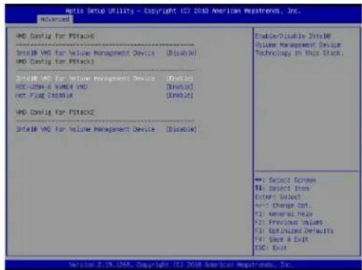
text_image
Auto Setup Utility - Copyright © 2010 American Mystrechn, Inc. Advanced VMD Config for P1s Select VMD for Value Management Device (Disable) VMD Config for P1s Select VMD for Value Management Device (Disable) VMD-USB & VMD VMD (Disable) VMT FLOW Disable (Enable) VMD Config for P1s Select VMD for Value Management Device (Disable) Enable/Disable SelectV Volume Management Device Technology in this Stock, Select Screen Select Item Enter Select +/- Change Out F1: General Help F2: Previous Values F3: Optimized Defaults F4: Save & Exit CID: Exit Version 3.19.208, Copyright © 2010 American Mystrechn, Inc.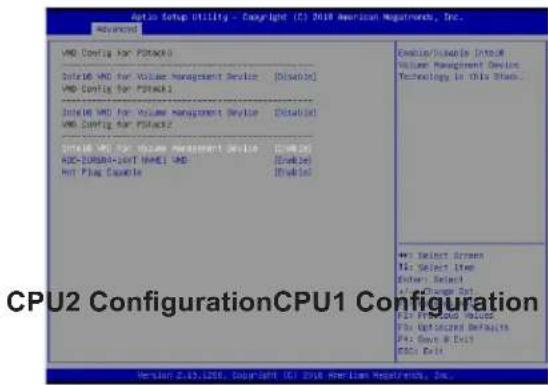
text_image
Auto Setup Utility - Copyright (C) 2018 American Guatemala, Inc. AutoSetup VMD Config For Portfolio Initise VMD for Volume Management Device [Disable] VMD Config For Portfolio Initise VMD for Volume Management Device [Disable] VMD Config For Portfolio Initise VMD for Volume Management Device [Disable] ADC-COMBAT-KEY NAME: VMD [Disable] Hot Flag Currency [Disable] Enable/Disable Into Our Volumet Management Device Technology in this block...Select Screen
Select Item
Enter SelectChange Set
Fid From Home to Close Fid Optimized Defaults Fid Cause & Exit Fid Data CPU2 ConfigurationCPU1 Configuration Version 2.47.1206, Copyright (C) 2018 American Guatemala, Inc.Figure F-2. BIOS VMD Setting Example for 24 Drives
- Press [F4] to save the configuration and reboot the system.
- Press [DEL] to enter BIOS.
- Switch to Advanced > Intel® Virtual RAID on CPU > All Intel VMD Controllers > Create RAID Volume.
- Set Name.
- Set RAID Level.
- If cross-controller RAID is required, select Enable RAID spanned over VMD Controller as shown in Figure F-4.

text_image
Auto Setup Utility - Copyright (C) 2018 American Markets, Inc. Created Create R&D Volume Name: Volume R&D Level: [USD] (Price) Director R&D Scanned Over AND Scheduling: $1 Select Division DNTL DESPECKSHATTI DRAPLEDSHOPHIPS: D0 DNTL DESPECKSHATTI DRAPLEDSHOPHIPS: D1 DNTL DESPECKSHATTI DRAPLEDSHOPHIPS: D2 DNTL DESPECKSHATTI DRAPLEDSHOPHIPS: D3 DNTL DESPECKSHATTI DRAPLEDSHOPHIPS: D4 Strip Size: [100%] Capacity: 100% ■ Create Volume E = To Select Struts ←: Select Struts PA: Select Struts Enter: Select +1: Design Not F1: General Help C2: Preview Values P2: Selection Defaults Fri: Save & Exit ISC1 Exit Version 2.15.2006. Copyright 157 2018 American Markets, Inc.Figure F-3. Created Volume without enabling RAID spanned over VMD controller

text_image
Auto Setup Utility - Copyright (C) 2008 American Markets, Inc. Advanced Create RMS Volume Name: A#D Level: A#D Volume Create RMS Volume over RMS Controller: [N] Select Blocks: [NTL, SOUTEXCHADY1 SOUTEL/SPRINGAPOPE] [NTL, SOUTEXCHADY1 SOUTEL/SPRINGAPOPE] [NTL, SOUTEXCHADY1 SOUTEL/SPRINGAPOPE] [NTL, SOUTEXCHADY1 SOUTEL/SPRINGAPOPE] Key by Box: Capacity (KB): 14356.88 Drive Volume A > No Select Box +/- Select Screen F1: Select Item Enter Select +/- Change Dot... F1: Generate Head F2: Previous Value F3: Options Defaults F4: Save & Exit ECC by End Version 2.17.2007, Copyright (C) 2008 American Markets, Inc.Figure F-4. Created Volume with enabling RAID spanned over VMD controller
- Select specific disks for RAID with an [X].
• RAID0: Select at least two [2 - 24] disks
• RAID1: Select only two disks
• RAID5: Select at least three [3 - 24] disks
• RAID10: Select only four disks
- Select Strip Size (Default 64KB).
- Select Create Volume.
- If another RAID is needed, start again at step 6.
- Press [F4] to save and reboot.
F.3 Status Indications
An LED indicator on the drive carrier shows the RAID status of the drive.
| Drive Carrier Status LED Indicator | |
| Status State (red) | |
| Normal function Off | |
| Locating 4 Hz blink | |
| Fault Solid on | |
| Rebuilding 1 Hz Blink | |
IBPI SFF 8489 Defined Status LED States
F.4 Hot Swap Drives
Intel VMD enables hot-plug and hot-unplug for NVMe SSDs, whether from Intel or other manufacturers. Under vSphere ESXi, several steps are necessary to avoid potential stability issues. See the information at link [1] below.
Hot-unplug
- Prevent devices from being re-detected during rescan:
esxcli storage core claiming autoclaim --enabled=false
- Unmount the VMFS volumes on the device. Check [2] for details.
- Detach the device. Check [3] for details.
- Physically remove the device.
Hot-plug
• Physically install the device.
ESXi will automatically discover NVMe SSDs, but a manual scan may be required in some cases.
Related Information Links
[1] https://kb.vmware.com/s/article/2151404
[2] https://docs.vmware.com/en/VMware-vSphere/6.5/com.vmware.vsphere.storage.doc/GUID-1B56EF97-F60E-4F21-82A7-8F2A7294604D.html
[3] https://docs.vmware.com/en/VMware-vSphere/6.5/com.vmware.vsphere.storage.doc/GUID-F2E75F67-740B-4406-9F0C-A2D99A698F2A.html