SuperServer 2029U-TR25M - Server Supermicro - Free user manual and instructions
Find the device manual for free SuperServer 2029U-TR25M Supermicro in PDF.

User questions about SuperServer 2029U-TR25M Supermicro
0 question about this device. Answer the ones you know or ask your own.
Ask a new question about this device
Download the instructions for your Server in PDF format for free! Find your manual SuperServer 2029U-TR25M - Supermicro and take your electronic device back in hand. On this page are published all the documents necessary for the use of your device. SuperServer 2029U-TR25M by Supermicro.
USER MANUAL SuperServer 2029U-TR25M Supermicro
natural_image
Front view of a server rack with multiple drive bays and indicator lights (no visible text or labels)USER'S MANUAL
Revision 1.0i
The information in this User's Manual has been carefully reviewed and is believed to be accurate. The vendor assumes no responsibility for any inaccuracies that may be contained in this document, and makes no commitment to update or to keep current the information in this manual, or to notify any person or organization of the updates. Please Note: For the most up-to-date version of this manual, please see our website at www.supermicro.com.
Super Micro Computer, Inc. ("Supermicro") reserves the right to make changes to the product described in this manual at any time and without notice. This product, including software and documentation, is the property of Supermicro and/or its licensors, and is supplied only under a license. Any use or reproduction of this product is not allowed, except as expressly permitted by the terms of said license.
IN NO EVENT WILL Super Micro Computer, Inc. BE LIABLE FOR DIRECT, INDIRECT, SPECIAL, INCIDENTAL, SPECULATIVE OR CONSEQUENTIAL DAMAGES ARISING FROM THE USE OR INABILITY TO USE THIS PRODUCT OR DOCUMENTATION, EVEN IF ADVISED OF THE POSSIBILITY OF SUCH DAMAGES. IN PARTICULAR, SUPER MICRO COMPUTER, INC. SHALL NOT HAVE LIABILITY FOR ANY HARDWARE, SOFTWARE, OR DATA STORED OR USED WITH THE PRODUCT, INCLUDING THE COSTS OF REPAIRING, REPLACING, INTEGRATING, INSTALLING OR RECOVERING SUCH HARDWARE, SOFTWARE, OR DATA.
Any disputes arising between manufacturer and customer shall be governed by the laws of Santa Clara County in the State of California, USA. The State of California, County of Santa Clara shall be the exclusive venue for the resolution of any such disputes. Supermicro's total liability for all claims will not exceed the price paid for the hardware product.
FCC Statement: This equipment has been tested and found to comply with the limits for a Class A digital device pursuant to Part 15 of the FCC Rules. These limits are designed to provide reasonable protection against harmful interference when the equipment is operated in an industrial environment. This equipment generates, uses, and can radiate radio frequency energy and, if not installed and used in accordance with the manufacturer's instruction manual, may cause harmful interference with radio communications. Operation of this equipment in a residential area is likely to cause harmful interference, in which case you will be required to correct the interference at your own expense.
California Best Management Practices Regulations for Perchlorate Materials: This Perchlorate warning applies only to products containing CR (Manganese Dioxide) Lithium coin cells. "Perchlorate Material-special handling may apply. See www.dtsc.ca.gov/hazardouswaste/perchlorate".

WARNING: This product can expose you to chemicals including lead, known to the State of California to cause cancer and birth defects or other reproductive harm. For more information, go to www.P65Warnings.ca.gov.
The products sold by Supermicro are not intended for and will not be used in life support systems, medical equipment, nuclear facilities or systems, aircraft, aircraft devices, aircraft/emergency communication devices or other critical systems whose failure to perform be reasonably expected to result in significant injury or loss of life or catastrophic property damage. Accordingly, Supermicro disclaims any and all liability, and should buyer use or sell such products for use in such ultra-hazardous applications, it does so entirely at its own risk. Furthermore, buyer agrees to fully indemnify, defend and hold Supermicro harmless for and against any and all claims, demands, actions, litigation, and proceedings of any kind arising out of or related to such ultra-hazardous use or sale.
Manual Revision 1.0i
Release Date: May 24, 2022
mk
Unless you request and receive written permission from Super Micro Computer, Inc., you may not copy any part of this document. Information in this document is subject to change without notice. Other products and companies referred to herein are trademarks or registered trademarks of their respective companies or mark holders.
Copyright © 2022 by Super Micro Computer, Inc.
All rights reserved.
Printed in the United States of America
Preface
About this Manual
This manual is written for professional system integrators and PC technicians. It provides information for the installation and use of this server. Installation and maintenance should be performed by experienced technicians only.
Please refer to the SYS-2029U-T Series server specifications page on our website for updates on supported memory, processors and operating systems (https://www.supermicro.com).
Notes
For your system to work properly, please follow the links below to download all necessary drivers/utilities and the user's manual for your server.
• Supermicro product manuals: https://www.supermicro.com/support/manuals/
- Product drivers and utilities: https://www.supermicro.com/wdl
- Product safety info: https://www.supermicro.com/about/policies/safety_information.cfm
If you have any questions, please contact our support team at: support@supermicro.com
This manual may be periodically updated without notice. Please check the Supermicro website for possible updates to the manual revision level.
Secure Data Deletion
A secure data deletion tool designed to fully erase all data from storage devices can be found on our website: https://www.supermicro.com/about/policies/disclaimer.cfm?url=/wdl/utility/Lot9_Secure_Data_Deletion_Utility/
Warnings
Special attention should be given to the following symbols used in this manual.

Warning! Indicates important information given to prevent equipment/property damage or personal injury.

Warning! Indicates high voltage may be encountered when performing a procedure.
Contents
Chapter 1 Introduction
1.1 Overview....8
1.2 Unpacking the System 8
1.3 System Features 9
1.4 Chassis Features ....10
Control Panel 10
Chassis Front....11
Chassis Rear....12
1.5 Motherboard Layout....13
Quick Reference 14
System Block Diagram....16
1.6 Where to Get Replacement Components....17
1.7 Returning Merchandise for Service....17
Chapter 2 Server Installation
2.1 Overview....18
2.2 Preparing for Setup....18
Choosing a Setup Location....18
Rack Precautions....18
Server Precautions....19
Rack Mounting Considerations....19
Ambient Operating Temperature....19
Airflow....19
Mechanical Loading....19
Circuit Overloading....20
Reliable Ground....20
2.3 Installing the Rails....21
Identifying the Rails....21
Releasing the Inner Rail....22
Installing the Inner Rails on the Chassis....23
Installing the Outer Rails onto the Rack....24
2.4 Installing the Chassis into a Rack....25
Removing the Chassis from the Rack....26
Chapter 3 Maintenance and Component Installation
3.1 Removing Power....27
3.2 Accessing the System....28
3.3 Motherboard Components....29
Processor and Heatsink Installation....29
The Processor 29
The Processor Carrier Assembly....29
Overview of the Processor Heatsink Module 30
Creating the Processor Carrier Assembly 31
Assembling the Processor Heatsink Module....32
Preparing the CPU Socket for Installation....33
Installing the Processor Heatsink Module 34
Memory 35
Memory Support 35
Memory Population Guidelines....36
Memory Population Sequence ....36
DCPMM Population Table (24 Slots) based on the 82xx/62xx/52xx/42xx....39
Installing Memory....41
Motherboard Battery 42
3.4 Chassis Components ....43
Storage Drives 43
Drive Carrier Indicators....43
Hot-Swap for NVMe Drives 46
Checking the Temperature of an NVMe Drive 47
M.2 Solid State Drives (with optional riser card)....48
System Cooling ....50
Fans....50
Installing the Air Shrouds....51
Checking the Server Air Flow....52
Overheating ....52
Power Supply....53
Power Supply LEDs....53
PCI Expansion Cards ....55
Installing Full Height Expansion Cards ....56
Installing the Low Profile Center Expansion Card....57
Installing the Internal Expansion Card ....58
Ultra Riser and Expansion Cards with Optional Storage Drives....59
Chapter 4 Motherboard Connections
4.1 Power Connections....60
4.2 Headers and Connectors ....61
Control Panel 64
4.3 Input/Output Ports 67
Rear I/O Ports 67
4.4 Jumpers....68
Explanation of Jumpers....68
4.5 LED Indicators....70
4.6 Storage Ports 72
Chapter 5 Software
5.1 Microsoft Windows OS Installation....73
5.2 Driver Installation....75
5.3 SuperDoctor® 5....76
5.4 IPMI 77
Chapter 6 UEFI BIOS
6.1 Introduction....78
Starting BIOS Setup Utility....78
6.2 Main Setup....78
6.3 Advanced Setup Configurations....80
6.4 Event Logs 126
6.5 BMC....128
6.6 Security....131
6.7 Boot....134
6.8 Save & Exit....136
Appendix A BIOS Error Codes
Appendix B Standardized Warning Statements for AC Systems
Appendix C System Specifications
Appendix D UEFI BIOS Recovery
Appendix E IPMI Crash Dump
Appendix F GPUs in 2U Ultra Systems
Appendix G CPU-Based RAID for NVMe
Contacting Supermicro
Headquarters
Address: Super Micro Computer, Inc.
980 Rock Ave.
San Jose, CA 95131 U.S.A.
Tel: +1 (408) 503-8000
Fax: +1 (408) 503-8008
Email: marketing@supermicro.com (General Information)
support@supermicro.com (Technical Support)
Website: www.supermicro.com
Europe
Address: Super Micro Computer B.V.
's-Hertogenbosch, The Netherlands
Tel: +31 (0) 73-6400390
Fax: +31 (0) 73-6416525
Email: sales@supermicro.nl (General Information)
support@supermicro.nl (Technical Support)
rma@supermicro.nl (Customer Support)
Website: www.supermicro.nl
Asia-Pacific
Address: Super Micro Computer, Inc.
3F, No. 150, Jian 1st Rd.
Zhonghe Dist., New Taipei City 235
Taiwan (R.O.C)
Tel: +886-(2) 8226-3990
Fax: +886-(2) 8226-3992
Email: support@supermicro.com.tw
Website: www.supermicro.com.tw
Chapter 1
Introduction
1.1 Overview
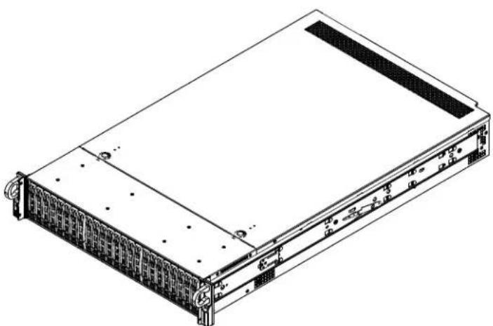
This chapter provides a brief outline of the functions and features of the SYS-2029U-T Series server. It is based on the X11DPU motherboard and the SC219U2AC4-R1K02-T chassis.
| SYS-2029U-T Series Models | ||
| System LAN Ports Ultra Riser Card | ||
| 2029U-TR25M Two | 25 GbE AOC-2UR68-M2TS | |
| 2029U-TR4 Four | GbE AOC-2UR68-I4G | |
| 2029U-TR4T Four | 10GBase-T AOC-2UR66-I4XTF | |
| 2029U-TRT Two | 10GBase-T AOC-2UR68-I2XT | |
| 2029U-TRTP Two | 10G SFP+ AOC-2UR68-I2XS | |
In addition to the motherboard and chassis, several important parts that are included with the system are listed below.
| Main Parts List | ||
| Description Part Number Quantity | ||
| Power supply modules PWS-1K02A-1R 2 | ||
| Backplane | BPN-SAS3-216A-N4 | 1 |
| Fans | FAN-0118L4 | 4 |
| Air Shrouds | MCP-310-82921-0N,MCP-310-82922-0N | 1 each |
| Heatsinks | SNK-P0068PS | 2 |
| Riser cards | RSC-R1UW-E8RRSC-R2UW-4E8 | 1 each |
| Rack mount rails | MCP-290-00057-0N | 1 set |
| PWS air shroud | MCP-310-81905-0B | 1 |
1.2 Unpacking the System
Inspect the box the system was shipped in and note if it was damaged in any way. If any equipment appears damaged, please file a damage claim with the carrier who delivered it.
Decide on a suitable location for the rack unit that will hold the server. It should be situated in a clean, dust-free area that is well ventilated. Avoid areas where heat, electrical noise and electromagnetic fields are generated. It will also require a grounded AC power outlet nearby. Be sure to read the precautions and considerations noted in Appendix B.
1.3 System Features
The following table is an overview of the main features of the SYS-2029U-T Series server.
| System Features |
| Motherboard |
| X11DPU |
| Chassis |
| SC219U2AC4-R1K02-T |
| CPU |
| Dual Intel Xeon 82xx/62xx/52xx/42xx/32xx or 81xx/61xx/51xx/41xx/31xx processors (in Socket P (LGA3647)) (Intel Xeon Processor Scalable Family). For the latest CPU/memory updates, refer to our website at http://www.supermicro.com/products/motherboard/Xeon/C620/X11DPU.cfm. |
| Memory |
| Twenty-four slots for up to 6 TB of 3DS Load Reduced DIMM (3DS LRDIMM), 3DS Registered DIMM (3DS RDIMM), or up to 3 TB of Load Reduced DIMM (LRDIMM) with speeds of up to 2933 MHz; support for Non-Volatile DIMM (NVDIMM) and Intel Optane DC Persistent Memory (DCPMM) |
| Chipset |
| Intel C621 |
| Expansion Slots |
| Two full-height, double-width, PCIe slots, four full-height, full-width PCIe slots, one low-profile PCIe slot, one internal low-profile PCIe slot (Ultra riser); Note: 2029U-TR4T model is different—see Ch 3 |
| Storage Drives |
| Twenty-four hot-swap 2.5" bays for fourteen SATA3 drives, or an option for twenty SAS3 plus four NVMe/SAS3 Two rear hot-swap 2.5" SATA/SAS3(Optional) M.2: Up to two PCIe M.2 or one SATA3 M.2 |
| Power |
| 1000 W redundant 80Plus Titanium level modules |
| Cooling |
| Four 8-cm heavy duty fans, two CPU heatsinks, two air shrouds to direct air flow |
| Input/Output |
| USB 3.0: Two ports on the rear I/O panel (USB 0/1)One serial port; one VGA port |
| LAN ports |
| Two or four, depending on the Utra riser card model; see previous page for detailsOne dedicated BMC port |
| Form Factor |
| 2U rackmount; (WxHxD) 17.2 x 3.5 x 28.5 in. (437 x 89 x 723 mm) |
1.4 Chassis Features
Control Panel
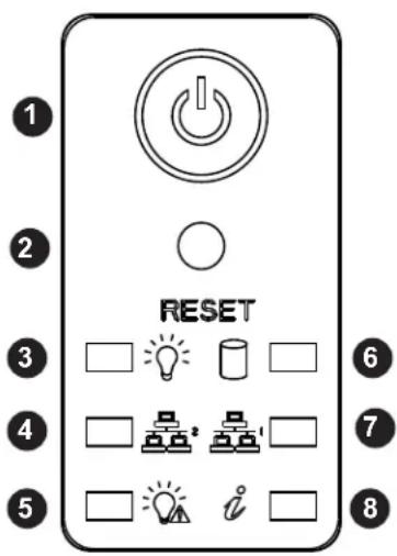
Power switches and status LEDs are located on the control panel on the front of the chassis.
text_image
1 2 RESET 3 4 5 6 7 8Figure 1-1. Control Panel
| Control Panel Features | ||
| Item Features Description | ||
| 1 Power button | The main power switch applies or removes primary power from the power supply to the server but maintains standby power. | |
| 2 Reset button Reboots the system. | ||
| 3 Power LED | Indicates power is being supplied to the system power supply units. This LED is illuminated when the system is operating normally. | |
| 4 NIC LED Indicates network activity on LAN2 when flashing. | ||
| 5 Power Fail LED Indicates a power supply module has failed. | ||
| 6 HDD LED Indicates activity on the hard drive when flashing. | ||
| 7 NIC LED Indicates network activity on LAN1 when flashing. | ||
| 8 Information LED Alerts operator to several states, as noted in the table below | ||
| Information LED | |
| Status Description | |
| Continuously on and red | An overheat condition has occurred. (This may be caused by cable congestion.) |
| Blinking red (1Hz) Fan failure, check for an inoperative fan. | |
| Blinking red (0.25Hz) | Power failure, check for a non-operational power supply. |
| Solid blue | UID has been activated locally to locate the server in a rack environment. |
| Blinking blue | UID has been activated using IPMI to locate the server in a rack environment. |
Chassis Front
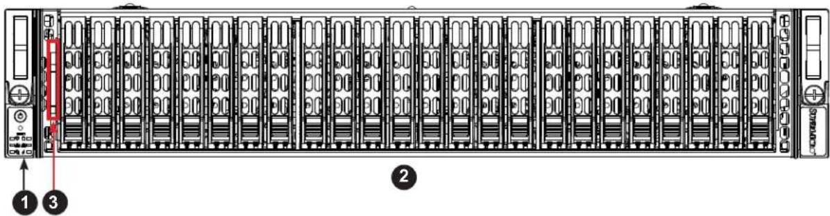
The illustration below shows the features included on the front of the chassis. Externally accessible hard drive carriers display status lights.
text_image
Diagram of a server rack with labeled ports and numbered components, showing front panel and side view.Figure 1-2. Front View
| Chassis Front Features | ||
| Item Features Description | ||
| 1 Control | Panel Power buttons and status indicators | |
| 2 Storage | Drives | Twenty-four 2.5" drive bays; see the "Storage Drive" section in Section 3.4 for details |
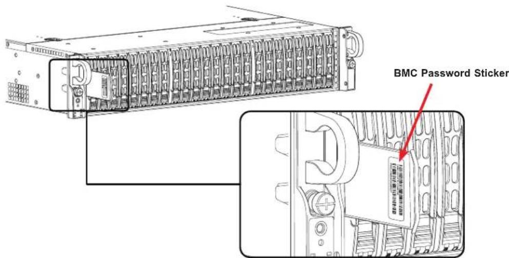
| 3 | Service/Asset Tag | Pull-out identifier (with BMC ADMIN default password sticker) |
text_image
BMC Password StickerFigure 1-3. Location of the BMC Password Label
Chassis Rear
The illustration below shows the features included on the rear of the chassis. Power supply modules display status lights.

text_image
Diagram of a server rack with labeled components and numbered parts, showing internal layout and ports.Figure 1-4. Rear View
| Chassis Rear Features | ||
| Item Features Description | ||
| 1 Power | Supply Two redundant | ant power supply modules, PWS1 on the left, PWS2 on the right |
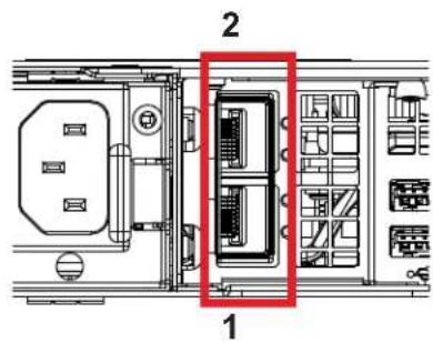
| 2 LAN | Two or four LAN ports, depending on your Ultra riser card (see Section 1.1 Overview for details; also see LAN numbering description below) | |
| 3 USB | Two USB 3.0 ports | |
| 4 BMC | LAN Dedicated LAN | port for |
| 5 COM | Serial port | |
| 6 UID | UID indicator and button to toggle the UID indicators | |
| 7 VGA | Video port | |
| 8 PCI | One PCIe low-profile slot | |
| 9 PCI | Six PCIe full-height slots | |

text_image
3 4 1 2Two or four 1G/10G LAN Ports
text_image
2 1Two 25G LAN Ports
Figure 1-5. LAN Numbering
1.5 Motherboard Layout
Below is a layout of the X11DPU with jumper, connector and LED locations shown. See the table on the following page for descriptions. For detailed descriptions, pinout information and jumper settings, refer to Chapter 4.
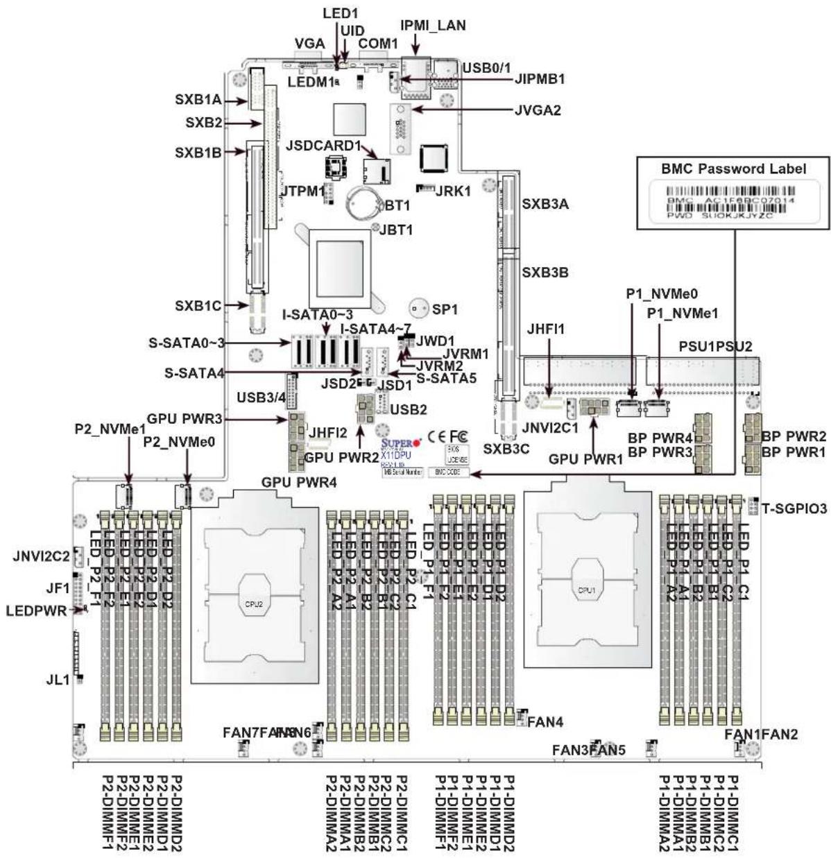
text_image
LED1 UID COM1 IPMI_LAN VGA LEDM1a JSDCARD1 JTPM1 BT1 JRT1 JRPMB1 JVGA2 USB0/1 JIPMB1 SXB3A SXB3B SP1 I-SATA0~3 I-SATA4~7 JWD1 JVRM1 JVRM2 S-SATA5 JSD2F JSD1 USB3/4 USB2 JHFI2 JNVI2C1 P1_NVMe0 P1_NVMe1 PSU1PSU2 SXB3C GPU PWR1 GPU PWR2 CPU SUPER X11DPU CE FC BMC CODE JNVI2C1 BP PWR4 BP PWR3 BP PWR2 BP PWR1 T-SGPIO3 JNVI2C2 JF1 LEDPWR JL1 P2-DIMMF1 P2-DIMMD2 P2-DIMME1 P2-DIMMD1 P2-DIMME2 P2-DIMMD2 P2-DIMME1 P2-DIMMD2 P2-DIMME2 P2-DIMMD1 P2-DIMME1 P2-DIMMD2 P2-DIMME2 P2-DIMMD1 P2-DIMME1 P2-DIMMD2 P2-DIMME2 P2-DIMMD1 P2-DIMME1 P2-DIMMD2 P2-DIMME2 P2-DIMMD1 P2-DIMME1 P2-DIMMD2 FAN7FAN6N6 FAN3FAN5 FAN1FAN2Figure 1-6. Motherboard Layout
Quick Reference
Jumper Description Default Setting
JBT1 CMOS Clear Open (Normal)
JWD1 Watch Dog Pins 1-2 (Reset)
Connector Description
| BP PWR1/2/3/4 8-pin power connectors 1/2/3/4 for backplane use | |
| BT1 Onboard battery | |
| COM1 COM port (COM1) on the I/O backplane | |
| FAN1 - FAN8 System/CPU fan headers | |
| GPU PWR1/2/3/4 8-pin power connectors 1/2/3/4 used for GPU devices | |
| IPMI_LAN Dedicated IPMI LAN Port | |
| I-SATA0-3, I-SATA4-7 Intel PCH SATA 3.0 ports (0-3, 4-7) | |
| JF1 | Front control panel header |
| JHFI1/JHFI2 | Host Fabric Interface sideband connection headers—not supported in this system |
| JIPMB1 | 4-pin BMC external IC header (for an IPMI card) |
| JL1 | Chassis intrusion header |
| JNVI2C1/2 | NVMe SMBus (I2C) headers used for PCIe hot-plug SMBus clock and data connections (a proprietary NVMe add-on card and cable are required; available only for Supermicro complete systems) |
| JRK1 | RAID_Key for onboard NVMe devices |
| JSD1/JSD2 | SATA DOM power connectors 1/2 |
| JSDCARD1 | Micro SD card slot (reserved for manufacture use) |
| JTPM1 | Trusted Platform Module/Port 80 connector |
| JUIDB2 | UID (Unit Identifier) switch |
| JVGA2 | Front VGA Port |
| JVRM1/JVRM2 | VRM I2C headers |
| P1_NVMe0/1 & P2_NVMe0/1 | Non-Volatile Memory Express (NVMe) 3.0 devices 0/1 supported by CPU1 & CPU2 |
| PSU1/PSU2 | Power Supply Unit (PSU) Connector 1/Power Supply Unit Connector 2 |
| S-SATA0-3 | SATA 3.0 ports 0-3 supported by Intel SCU chip |
| S-SATA4/S-SATA5 | SATA3.0 ports with power-pin built-in w/support of SuperDOM (Device-On Module) |
| SP1 | Internal speaker/buzzer |
| SXB1A/SXB1B/SXB1C | PCIe 3.0 (x16 + x16) slot supported by CPU2 for proprietary riser card (w/left riser card support) |
| SXB2 | PCIe 3.0 x8 (in x16) slot supported by CPU2 for center right riser card support |
| SXB3A/SXB3B/SXB3C | PCIe 3.0 (x16 + x16 + x8) slot from CPU1 for far_right ultra riser (SAS3 AOM & LAN options) |
| T-SGPIO3 | Serial_Link General Purpose I/O header for S-SATA4/5 |
| USB0/1 | Backplane Universal Serial Bus (USB) 3.0 ports 0/1 |
| USB3/4 | Front Accessible USB 3.0 header for USB 3/4 connections |
| USB2 | USB 3.0 Type A Header |
| VGA | VGA Port |
LED Description State: Status
| LED1 UID (Unit Identifier) LED Solid Blue: Unit Identified |
| LEDM1 BMC Heartbeat LED Blinking Green: BMC Normal |
| LEDPWR Onboard Power LED Solid Green: Power On |
Memory LED Description Status
| LED_P1_A1/LED_P1_A2 | Memory Fault LEDs for Memory Module P1_A1/Memory Module P1_A2 | Solid Red: Memory Error |
| LED_P1_B1/LED_P1_B2 | Memory Fault LEDs for Memory Module P1_B1/Memory Module P1_B2 | Solid Red: Memory Error |
| LED_P1_C1/LED_P1_C2 | Memory Fault LEDs for Memory Module P1_C1/Memory Module P1_C2 | Solid Red: Memory Error |
| LED_P1_D1/LED_P1_D2 | Memory Fault LEDs for Memory Module P1_D1/Memory Module P1_D2 | Solid Red: Memory Error |
| LED_P1_E1/LED_P1_E2 | Memory Fault LEDs for Memory Module P1_E1/Memory Module P1_E2 | Solid Red: Memory Error |
| LED_P1_F1/LED_P1_F2 | Memory Fault LEDs for Memory Module P1_F1/Memory Module P1_F2 | Solid Red: Memory Error |
| LED_P2_A1/LED_P2_A2 | Memory Fault LEDs for Memory Module P2_A1/Memory Module P2_A2 | Solid Red: Memory Error |
| LED_P2_B1/LED_P2_B2 | Memory Fault LEDs for Memory Module P2_B1/Memory Module P2_B2 | Solid Red: Memory Error |
| LED_P2_C1/LED_P2_C2 | Memory Fault LEDs for Memory Module P2_C1/Memory Module P2_C2 | Solid Red: Memory Error |
| LED_P2_D1/LED_P2_D2 | Memory Fault LEDs for Memory Module P2_D1/Memory Module P2_D2 | Solid Red: Memory Error |
| LED_P2_E1/LED_P2_E2 | Memory Fault LEDs for Memory Module P2_E1/Memory Module P2_E2 | Solid Red: Memory Error |
| LED_P2_F1/LED_P2_F2 | Memory Fault LEDs for Memory Module P2_F1/Memory Module P2_F2 | Solid Red: Memory Error |
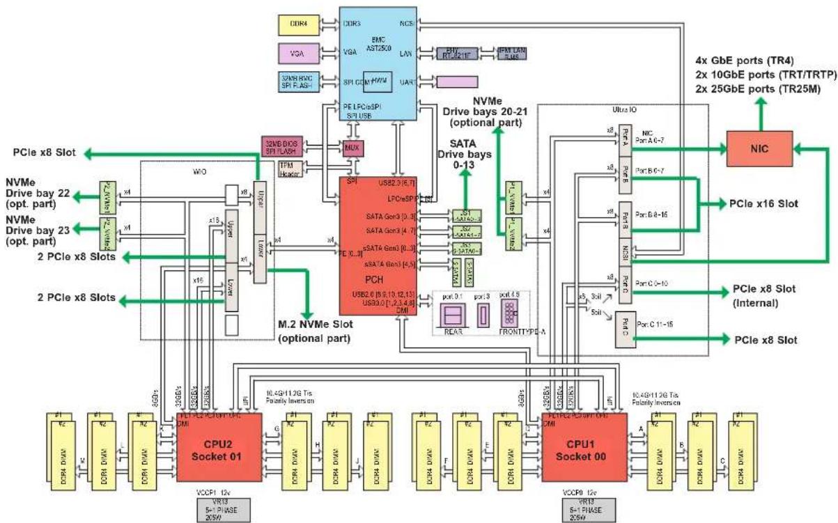
System Block Diagram
flowchart
graph TD
    subgraph_PCIe_x8_Slot["PCIe x8 Slot"]
        A1["DCR4"] --> B1["DDR3"]
        A2["VGA"] --> B2["SP1 CCM"]
        A3["SAS RWC SPI F.AS+"] --> B3["SP1 USB"]
        B1 --> C1["EMC AST25.0"]
        B2 --> C2["SPI CCM"]
        B3 --> C3["M7PWM"]
        C1 --> D1["PE LFCoSPI S/I USB"]
        C2 --> D2["MUX"]
        C3 --> D3["32MB DOS SPI FLASH"]
        D1 --> E1["USB2.0 (6.7)"]
        D2 --> E2["USB2.0 (6.7)"]
        D3 --> E3["USB2.0 (6.7)"]
        E1 --> F1["TFM Iboxc"]
        E2 --> F2["TFM Iboxc"]
        E3 --> F3["TFM Iboxc"]
        F1 --> G1["USB3.0 (1,2,3,4,6) CM"]
        F2 --> G2["USB3.0 (1,2,3,4,6) CM"]
        G1 --> H1["MUX"]
        G2 --> H2["MUX"]
        H1 --> I1["CPU2 Socket 01"]
        H2 --> I2["CPU2 Socket 01"]
        H3 --> I3["CPU2 Socket 01"]
        H4 --> I4["CPU2 Socket 01"]
        H5 --> I5["CPU2 Socket 01"]
        H6 --> I6["CPU2 Socket 01"]
        H7 --> I7["CPU2 Socket 01"]
        H8 --> I8["CPU2 Socket 01"]
        H9 --> I9["CPU2 Socket 01"]
        H10 --> I10["CPU2 Socket 01"]
        H11 --> I11["CPU2 Socket 01"]
        H12 --> I12["CPU2 Socket 01"]
        H13 --> I13["CPU2 Socket 01"]
        H14 --> I14["CPU2 Socket 01"]
        H15 --> I15["CPU2 Socket 01"]
        H16 --> I16["CPU2 Socket 01"]
        H17 --> I17["CPU2 Socket 01"]
        H18 --> I18["CPU2 Socket 01"]
        H19 --> I19["CPU2 Socket 01"]
        H20 --> I20["CPU2 Socket 01"]
    end

    subgraph M.2_NVMe_Slot["M.2 NVMe Slot (optional part)"]
        B1 --> C1
        B2 --> C2
        B3 --> C3
        B4 --> C4
        B5 --> C5
        B6 --> C6
        B7 --> C7
        B8 --> C8
        B9 --> C9
        B10 --> C10
    end

    subgraph_CPU_1_Socket_CPU_PCM["CPU1_Socket 00"]
        C1 --> D1
        C2 --> D2
        C3 --> D3
        C4 --> D4
        C5 --> D5
        C6 --> D6
        C7 --> D7
        C8 --> D8
        C9 --> D9
        C10 --> D10
    end

    subgraph CPU_2_Socket_CPU_PCM
        C1 --> D1
        C2 --> D2
        C3 --> D3
        C4 --> D4
        C5 --> D5
        C6 --> D6
        C7 --> D7
        C8 --> D8
        C9 --> D9
    end

    subgraph CPU_3_Socket_CPU_PCM
        C1 --> D1
        C2 --> D2
        C3 --> D3
        C4 --> D4
        C5 --> D5
        C6 --> D6
        C7 --> D7
        C8 --> D8
    end

    subgraph CPU_4_Socket_CPU_PCM
        C1 --> D1
        C2 --> D2
        C3 --> D3
        C4 --> D4
        C5 --> D5
        C6 --> D6
        C7 --> D7
    end

    subgraph CPU_5_Socket_CPU_PCM
        C1 --> D1
        C2 --> D2
        C3 --> D3
        C4 --> D4
        C5 --> D5
        C6 --> D6
    end

    subgraph CPU_6_Socket_CPU_PCM
        C1 --> D1
        C2 --> D2
        C3 --> D3
        C4 --> D4
        C5 --> D5
    end

    subgraph CPU_7_Socket_CPU_PCM
        C1 --> D1
        C2 --> D2
        C3 --> D3
        C4 --> D4
        C5 --> D5
    end

    subgraph CPU_8_Socket_CPU_PCM
        C1 --> D1
        C2 --> D2
        C3 --> D3
        C4 --> D4
        C5 --> D5

    end

    subgraph CPU_9_Socket_CPU_PCM
        C1 --> D1
        C2 --> D2
        C3 --> D3
        C4 --> D4
    end

    subgraph CPU_10_Socket_CPU_PCM
        C1 --> D1
        C2 --> D2
        C3 --> D3
        C4 --> D4
    end

    subgraph CPU_11_Socket_CPU_PCM
        C1 --> D1
        C2 --> D2
        C3 --> D3
    end

    subgraph CPU_12_Socket_CPU_PCM
        C1 --> D1
        C2 --> D2
        C3 --> D3
    end

    subgraph CPU_13_Socket_CPU_PCM
        C1 --> D1
        C2 --> D2
        C3 --> D3
    end

    subgraph CPU_14_Socket_CPU_PCM
        C1 --> D1
        C2 --> D2
        C3 --> D3
    end

    subgraph CPU_15_Socket_CPU_PCM
        C1 --> D1
        C2 --> D2
        C3 --> D3
    end

    subgraph CPU_16_Socket_CPU_PCM
        C1 --> D1
        C2 --> D2
        C3 --> D3

    subgraph CPU_17_Socket_CPU_PCM
        C1 --> D1
        C2 --> D2
        C3 --> D3

    subgraph CPU_18_Socket_CPU_PCM
        C1 --> D1
        C2 --> D2

    subgraph CPU_19_Socket_CPU_PCM
        C1 --> D1
        C2 --> D2

    subgraph CPU_20_Socket_CPU_PCM
        C1 --> D1
        C2 --> D2

    subgraph CPU_21_Socket_CPU_PCM
        C1 --> D1
        C2 --> D2

    subgraph CPU_22_Socket_CPU_PCM
        C1 --> D1
        C2 --> D2

    subgraph CPU_23_Socket_CPU_PCM
        C1 --> D1
        C2 --> D2

    subgraph CPU_24_Socket_CPU_PCM
        C1 --> D1
        C2 --> D2

    subgraph CPU_25_Socket_CPU_PCM
        C1 --> D1
        C2 --> D2

    subgraph CPU_26_Socket_CPU_PCM
        C1 --> D1
        C2 --> D2

    subgraph CPU_27_Socket_CPU_PCM
        C1 --> D1
        C2 --> D2

    subgraph CPU_28_Socket_CPU_PCM
        C1 --> D1
        C2 --> D2

    subgraph CPU_29_Socket_CPU_PCM
        C1 --> D1
        C2 --> D2

    subgraph CPU_30_Socket_CPU_PCM
        C1 --> D1
        C2 --> D2

    subgraph CPU_31_Socket_CPU_PCM
        C1 --> D1
        C2 --> D2

    subgraph CPU_32_Socket_CPU_PCM
        C1 --> D1
        C2 --> D2

    subgraph CPU_33_Socket_CPU_PCM
        C1 --> D1
        C2 --> D2

    subgraph CPU_34_Socket_CPU_PCM
        C1 --> D1
        C2 --> D2

    subgraph CPU_35_Socket_CPU_PCM
        C1 --> D1
        C2 --> D2

    subgraph CPU_36_Socket_CPU_PCM
        C1 --> D1
        C2 --> D2

    subgraph CPU_37_Socket_CPU_PCM
        C1 --> D1
        C2 --> D2

    subgraph CPU_38_Socket_CPU_PCM
        C1 --> D1
        C2 --> D2

    subgraph CPU_39_Socket_CPU_PCM
        C1 --> D1
        C2 --> D2

    subgraph CPU_40_Socket_CPU_PCM

    style CPU_40_Socket_CPU_PCM fill:#f9f,stroke:#333,stroke-width:2px
Figure 1-7. System Block Diagram, 2029U-TR4/TRT/TRTP/TR25M Models

flowchart
NVIDIA CPU architecture diagram showing data flow between Intel XL710+X557, M.2 NVMe slots, and peripheral components like CPU01/00, SATA, and I/O ports.Figure 1-8. System Block Diagram, 2029U-TR4T Model
1.6 Where to Get Replacement Components
If you need replacement parts for your system, to ensure the highest level of professional service and technical support, purchase exclusively from our Supermicro Authorized Distributors/System Integrators/Resellers. A list can be found at: http://www.supermicro.com. Click the "Where to Buy" link.
1.7 Returning Merchandise for Service
A receipt or copy of your invoice marked with the date of purchase is required before any warranty service will be rendered. You can obtain service by calling your vendor for a Returned Merchandise Authorization (RMA) number. When returning to the manufacturer, the RMA number should be prominently displayed on the outside of the shipping carton, and mailed prepaid or hand-carried. Shipping and handling charges will be applied for all orders that must be mailed when service is complete.
For faster service, RMA authorizations may be requested online (http://www.supermicro.com/support/rma/).
Whenever possible, repack the chassis in the original Supermicro carton, using the original packaging material. If these are no longer available, be sure to pack the chassis securely, using packaging material to surround the chassis so that it does not shift within the carton and become damaged during shipping.
This warranty only covers normal consumer use and does not cover damages incurred in shipping or from failure due to the alteration, misuse, abuse or improper maintenance of products.
During the warranty period, contact your distributor first for any product problems.
Chapter 2
Server Installation
2.1 Overview
This chapter provides advice and instructions for mounting your system in a server rack. If your system is not already fully integrated with processors, system memory etc., refer to Chapter 4 for details on installing those specific components.
Caution: Electrostatic Discharge (ESD) can damage electronic components. To prevent such damage to PCBs (printed circuit boards), it is important to use a grounded wrist strap, handle all PCBs by their edges and keep them in anti-static bags when not in use.
2.2 Preparing for Setup
The box in which the system was shipped should include the rackmount hardware needed to install it into the rack. Please read this section in its entirety before you begin the installation.
Choosing a Setup Location
- The system should be situated in a clean, dust-free area that is well ventilated. Avoid areas where heat, electrical noise and electromagnetic fields are generated.
- Leave enough clearance in front of the rack so that you can open the front door completely (\~25 inches) and approximately 30 inches of clearance in the back of the rack to allow sufficient space for airflow and access when servicing.
- This product should be installed only in a Restricted Access Location (dedicated equipment rooms, service closets, etc.).
- This product is not suitable for use with visual display workplace devices according to §2 of the German Ordinance for Work with Visual Display Units.
Rack Precautions
- Ensure that the leveling jacks on the bottom of the rack are extended to the floor so that the full weight of the rack rests on them.
- In single rack installations, stabilizers should be attached to the rack. In multiple rack installations, the racks should be coupled together.
- Always make sure the rack is stable before extending a server or other component from the rack.
- You should extend only one server or component at a time - extending two or more simultaneously may cause the rack to become unstable.
Server Precautions
- Review the electrical and general safety precautions in Appendix B.
- Determine the placement of each component in the rack before you install the rails.
- Install the heaviest server components at the bottom of the rack first and then work your way up.
- Use a regulating uninterruptible power supply (UPS) to protect the server from power surges and voltage spikes and to keep your system operating in case of a power failure.
- Allow any drives and power supply modules to cool before touching them.
- When not servicing, always keep the front door of the rack and all covers/panels on the servers closed to maintain proper cooling.
Rack Mounting Considerations
Ambient Operating Temperature
If installed in a closed or multi-unit rack assembly, the ambient operating temperature of the rack environment may be greater than the room's ambient temperature. Therefore, consideration should be given to installing the equipment in an environment compatible with the manufacturer's maximum rated ambient temperature (TMRA).
Airflow
Equipment should be mounted into a rack so that the amount of airflow required for safe operation is not compromised.
Mechanical Loading
Equipment should be mounted into a rack so that a hazardous condition does not arise due to uneven mechanical loading.
Circuit Overloading
Consideration should be given to the connection of the equipment to the power supply circuitry and the effect that any possible overloading of circuits might have on overcurrent protection and power supply wiring. Appropriate consideration of equipment nameplate ratings should be used when addressing this concern.
Reliable Ground
A reliable ground must be maintained at all times. To ensure this, the rack itself should be grounded. Particular attention should be given to power supply connections other than the direct connections to the branch circuit (i.e. the use of power strips, etc.).

To prevent bodily injury when mounting or servicing this unit in a rack, you must take special precautions to ensure that the system remains stable. The following guidelines are provided to ensure your safety:
- This unit should be mounted at the bottom of the rack if it is the only unit in the rack.
- When mounting this unit in a partially filled rack, load the rack from the bottom to the top with the heaviest component at the bottom of the rack.
- If the rack is provided with stabilizing devices, install the stabilizers before mounting or servicing the unit in the rack.
- Slide rail mounted equipment is not to be used as a shelf or a work space.
2.3 Installing the Rails
There are a variety of rack units on the market, which may require a slightly different assembly procedure. This rail set fits a rack between 26.8" and 36.4" deep.
The following is a basic guideline for installing the system into a rack with the rack mounting hardware provided. You should also refer to the installation instructions that came with the specific rack you are using.
Identifying the Rails
The chassis package includes two rail assemblies. Each assembly consists of three sections: An inner rail that secures directly to the chassis, an outer rail that secures to the rack, and a middle rail which extends from the outer rail. These assemblies are specifically designed for the left and right side of the chassis and labeled.
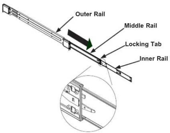
text_image
Outer Rail Middle Rail Locking Tab Inner RailFigure 2-1. Identifying the Outer Rail, Middle Rail and Inner Rail (Left Rail Assembly Shown)
Releasing the Inner Rail
Each inner rail has a locking latch. This latch prevents the server from coming completely out of the rack when when the chassis is pulled out for servicing.
To mount the rail onto the chassis, first release the inner rail from the outer rails.
- Pull the inner rail out of the outer rail until it is fully extended as illustrated below.
- Press the locking tab down to release the inner rail.
- Pull the inner rail all the way out.
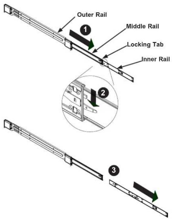
text_image
Outer Rail 1 Middle Rail Locking Tab Inner Rail 2 3Figure 2-2. Extending and Releasing the Inner Rail
Installing the Inner Rails on the Chassis
Installing the Inner Rails
- Identify the left and right inner rails. They are labeled.
- Place the inner rail firmly against the side of the chassis, aligning the hooks on the side of the chassis with the holes in the inner rail.
- Slide the inner rail forward toward the front of the chassis until the quick release bracket snaps into place, securing the rail to the chassis.
- Optionally, you can further secure the inner rail to the chassis with screws.

text_image
Inner Rails 4 3 2 4Figure 2-3. Installing the Inner Rails
natural_image
Line drawing of a server rack unit with ventilation grilles and drive bays (no text or symbols)Figure 2-4. Inner Rails Installed on the Chassis
Installing the Outer Rails onto the Rack
Each end of the assembled outer rail includes a bracket with hooks and square, spring-loaded pegs to fit into the square holes in your rack.
Installing the Outer Rail
- Press upward on the locking tab at the rear end of the middle rail.
- Push the middle rail back into the outer rail.
- Hang the hooks on the front of the outer rail onto the square holes on the front of the rack. If desired, use screws to secure the outer rails to the rack.
- Pull out the rear of the outer rail, adjusting the length until it just fits within the posts of the rack.
- Hang the hooks of the rear section of the outer rail onto the square holes on the rear of the rack. Take care that the proper holes are used so the rails are level. If desired, use screws to secure the rear of the outer rail to the rear of the rack.

text_image
Technical diagram illustrating four stages of a mechanical assembly: linear tracking, vertical rail, horizontal rail, and vertical support.Figure 2-5. Extending and Mounting the Outer Rails
Note: The figure above is for illustrative purposes only. Always install servers at the bottom of the rack first.

Stability hazard. The rack stabilizing mechanism must be in place, or the rack must be bolted to the floor before you slide the unit out for servicing. Failure to stabilize the rack can cause the rack to tip over.

Warning: Do not pick up the server with the front handles. They are designed to pull the system from a rack only.
2.4 Installing the Chassis into a Rack
Once rails are attached to the chassis and the rack, you can install the server.

Warning: Mounting the system into the rack requires at least two people to support the chassis during installation. Please follow safety recommendations printed on the rails.
Installing the Chassis into a Rack
- Extend the outer rails as illustrated.
- Align the inner rails of the chassis with the outer rails on the rack.
- Slide the inner rails into the outer rails, keeping the pressure even on both sides. When the chassis has been pushed completely into the rack, it should click into the locked position.
- Optional screws may be used to hold the front of the chassis to the rack.

text_image
Ball-Bearing Shuttle 1 2 2 4Figure 2-6. Installing the Server into the Rack
Note: Keep the ball bearing shuttle locked at the front of the middle rail during installation.
Note: Figure is for illustrative purposes only. Always install servers to the bottom of a rack first.
Removing the Chassis from the Rack
Caution! The system is heavy. It is dangerous for a single person to remove it from the rack.
Have sufficient personnel or use a lift to support the chassis.
- Pull the chassis forward out the front of the rack until it stops.
- Press the release latches on each of the inner rails downward simultaneously and continue to pull the chassis forward and out of the rack.
Chapter 3
Maintenance and Component Installation
This chapter provides instructions on installing and replacing main system components. To prevent compatibility issues, only use components that match the specifications and/or part numbers given.
Installation or replacement of most components require that power first be removed from the system. Please follow the procedures given in each section.
3.1 Removing Power
Use the following procedure to ensure that power has been removed from the system. This step is necessary when removing or installing non hot-swap components or when replacing a non-redundant power supply.
- Use the operating system to power down the system.
- After the system has completely shut-down, disconnect the AC power cord(s) from the power strip or outlet. (If your system has more than one power supply, remove the AC power cords from all power supply modules.)
- Disconnect the power cord(s) from the power supply module(s).
3.2 Accessing the System
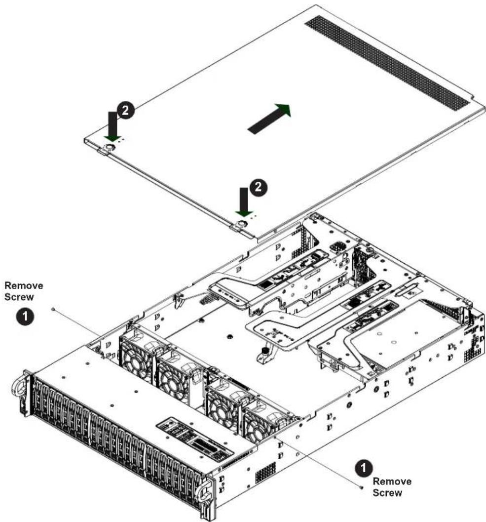
The SC219U chassis has a removable top cover to access internal components.
Removing the Top Cover
- Remove the two screws on each side of the cover, which secure the cover to the chassis. These two screws are optional and will not impact functionality if they are not installed.
- Press the two release buttons and slide the cover toward the rear and lift off.
Check that all ventilation openings on the top cover and the top of the chassis are clear and unobstructed.
Caution: Except for short periods of time, do not operate the server without the cover in place. The chassis cover must be in place to allow for proper airflow and to prevent overheating.
text_image
Remove Screw 1 2 1 Remove ScrewFigure 3-1. Removing the Chassis Cover
3.3 Motherboard Components
Processor and Heatsink Installation
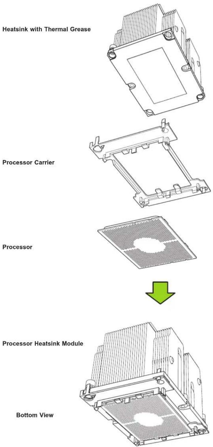
The processor (CPU) and processor carrier should be assembled together first to form the processor carrier assembly. This will be attached to the heatsink to form the processor heatsink module (PHM) before being installed onto the CPU socket.
Notes:
- Use ESD protection.
- Unplug the AC power cord from all power supplies after shutting down the system.
- Check that the plastic protective cover is on the CPU socket and none of the socket pins are bent. If they are, contact your retailer.
- When handling the processor, avoid touching or placing direct pressure on the LGA lands (gold contacts). Improper installation or socket misalignment can cause serious damage to the processor or CPU socket, which may require manufacturer repairs.
- Thermal grease is pre-applied on a new heatsink. No additional thermal grease is needed.
• Refer to the Supermicro website for updates on processor support. - All graphics in this manual are for illustration only. Your components may look different.
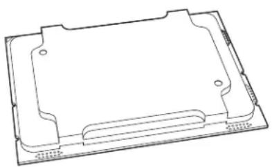
The Processor
The Intel Xeon 8100/6100/5100/4100/3100 processor series comes in two models: Fabric (F Model) and Non-Fabric (Non-F Model). Only the Non-Fabric model is supported for this system.
The Processor Carrier Assembly
The processor carrier assembly is the processor and a plastic carrier.
natural_image
Technical line drawing of a rectangular electronic component or enclosure with mounting holes and internal structure (no text or symbols)Processor

natural_image
Technical line drawing of a mechanical bracket or frame structure (no text or symbols)Processor Carrier
Overview of the Processor Heatsink Module
The Processor Heatsink Module (PHM) contains a heatsink, a processor carrier, and the processor.
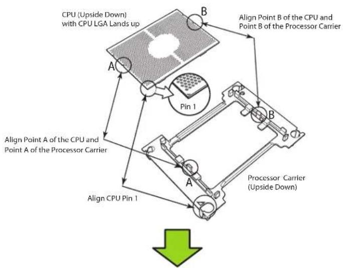
Creating the Processor Carrier Assembly
To install a processor into the processor carrier, follow the steps below:
- Hold the processor with the LGA lands (gold contacts) facing up. Locate the small, gold triangle in the corner of the processor and the corresponding hollowed triangle on the processor carrier. These triangles indicate pin 1. See the images below.
- Using the triangles as a guide, carefully align and place Point A of the processor into Point A of the carrier. Then gently flex the other side of the carrier for the processor to fit into Point B.
- Examine all corners to ensure that the processor is firmly attached to the carrier.
flowchart
graph TD
    A["CPU (Upside Down) with CPU LGA Lands up"] --> B["Pin 1"]
    B --> C["Align Point A of the CPU and Point A of the Processor Carrier"]
    B --> D["Align Point B of the CPU and Point B of the Processor Carrier"]
    B --> E["Processor Carrier (Upside Down)"]
    F["Align CPU Pin 1"] --> G["A"]
    G --> H["B"]
    H --> I["Pin 1"]
    I --> J["Computer Tower"]
    style A fill:#f9f,stroke:#333
    style B fill:#ccf,stroke:#333
    style C fill:#cfc,stroke:#333
    style D fill:#fcc,stroke:#333
    style E fill:#cff,stroke:#333
    style F fill:#ffc,stroke:#333
    style G fill:#cfc,stroke:#333
    style H fill:#fcc,stroke:#333
    style I fill:#ffc,stroke:#333
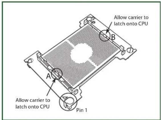
text_image
Allow carrier to latch onto CPU A B Allow carrier to latch onto CPU Pin 1Processor Carrier Assembly
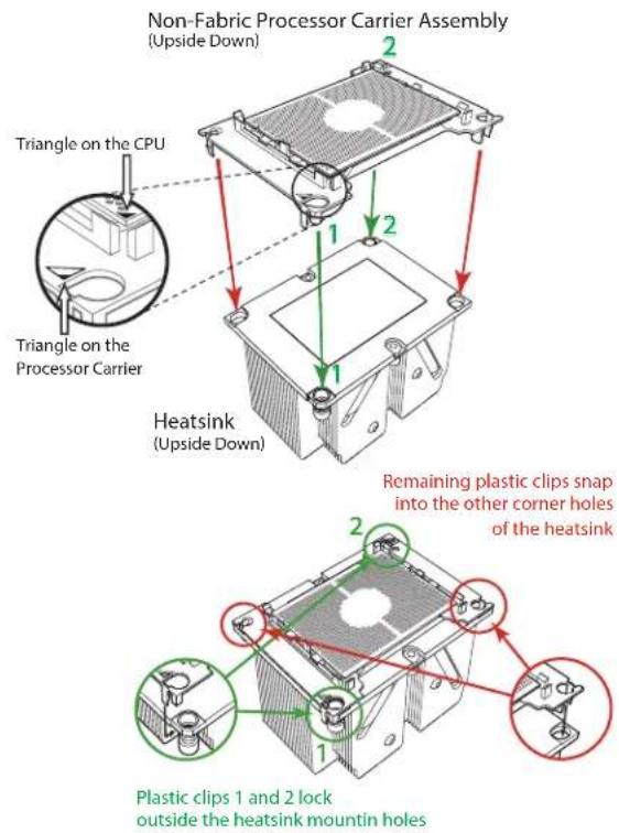
Assembling the Processor Heatsink Module
After creating the processor carrier assembly, mount it onto the heatsink to create the processor heatsink module (PHM):
-
Note the label on top of the heatsink, which marks the heatsink mounting holes as 1, 2, 3, and 4. If this is a new heatsink, the thermal grease has been pre-applied on the underside. Otherwise, apply the proper amount of thermal grease.
-
Turn the heatsink over with the thermal grease facing up. Hold the processor carrier assembly so the processor's gold contacts are facing up, then align the triangle on the assembly with hole 1 of the heatsink. Press the processor carrier assembly down. The plastic clips of the assembly will lock outside of holes 1 and 2, while the remaining clips will snap into their corresponding holes.
-
Examine all corners to ensure that the plastic clips on the processor carrier assembly are firmly attached to the heatsink.
text_image
Non-Fabric Processor Carrier Assembly (Upside Down) Triangle on the CPU Triangle on the Processor Carrier Heatsink (Upside Down) Remaining plastic clips snap into the other corner holes of the heatsink Plastic clips 1 and 2 lock outside the heatsink mountain holesPreparing the CPU Socket for Installation
This motherboard comes with a plastic protective cover on the CPU socket. Remove it carefully to install the Processor Heatsink Module (PHM).
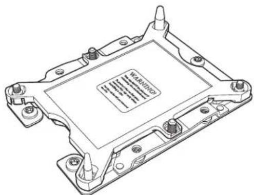
natural_image
Technical line drawing of a computer processor chassis with visible mounting holes and internal circuitry (no text or symbols)CPU Socket with Plastic Protective Cover
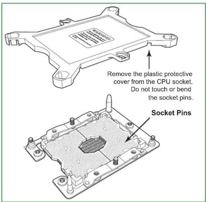
text_image
WARNING Remove the plastic protective cover from the CPU socket. Do not touch or bend the socket pins. Socket PinsInstalling the Processor Heatsink Module
After assembling the Processor Heatsink Module (PHM), install it onto the CPU socket:
- Align hole 1 of the heatsink with the printed triangle on the CPU socket. See the left image below.
- Make sure all four holes of the heatsink are aligned with the socket before gently placing the heatsink on top.
- With a T30 Torx-bit screwdriver, gradually tighten screws #1 – #4 to assure even pressure. The order of the screws is shown on the label on top of the heatsink. To avoid damaging the processor or socket, do not use a force greater than 12 lbf-in when tightening the screws.
- Examine all corners to ensure that the PHM is firmly attached to the socket.

text_image
Mounting the Processor Heatsink Module into the CPU socket (on the motherboard) Printed Triangle Large Guide Post Small Guide Post Printed Triangle T30 Torx Driver Use a torque of 12 lbf-in #1 #2 #3 #4 Tighten the screws in the sequence of 1, 2, 3, 4If at any time the PHM must be removed, power off, then loosen the screws in the sequence of #4, #3, #2, and #1.
Memory
Memory Support
The X11DPU has 24 DIMM slots for up to 6 TB of 3DS Load Reduced DIMM (3DS LRDIMM), 3DS Registered DIMM (3DS RDIMM), or up to 3 TB of Load Reduced DIMM (LRDIMM) with speeds of up to 2933 MHz. In addition it supports Non-Volatile DIMMs (NV-DIMM) and Intel Optane DC Persistent Memory (DCPMM).
| DDR4 Memory Support for 81xx/61xx/51xx/41xx/31xx Processors | ||||||
| Type | Ranks Per DIMM and Data Width | DIMM Capacity (GB) | Speed (MT/s) | |||
| One Slot per Channel | Two Slots per Channel | |||||
| DRAM Density | One DIMM per Channel | One DIMM per Channel | Two DIMMs per Channel | |||
| 4 Gb 8 Gb 1.2 Volts 1.2 Volts 1.2 Volts | ||||||
| RDIMM | SRx4 4 GB | 8 GB | 2666 2666 2666 | |||
| SRx8 8 GB | 16 GB | |||||
| DRx8 8 GB | 16 GB | |||||
| DRx4 16 GB | 32 GB | |||||
| RDIMM 3Ds | QRX4 N/A | 2H-64GB | ||||
| 8RX4 N/A | 4H-128GB | |||||
| LRDIMM QRx4 | 32 GB 64 GB | |||||
| LRDIMM 3Ds | QRx4 N/A | 2H-64GB | ||||
| 8Rx4 N/A | 4H-128 GB | |||||
| DDR4 Memory Support for 82xx/62xx/52xx/42xx/32xx Processors | |||||||
| Type | Ranks Per DIMM and Data Width | DIMM Capacity (GB) | Speed (MT/s) | ||||
| One Slot per Channel | Two Slots per Channel | ||||||
| DRAM Density | One DIMM per Channel | One DIMM per Channel | Two DIMMs per Channel | ||||
| 4 Gb* | 8 Gb | 16 Gb | 1.2 Volts | 1.2 Volts | 1.2 Volts | ||
| RDIMM | SRx4 4 GB | 8 GB | 16 GB | 2933** | 2933** | 2933** | |
| SRx8 8 GB | 16 GB | 32 GB | |||||
| DRx8 8 GB | 16 GB | 32 GB | |||||
| DRx4 16 GB | 32 GB | 64 GB | |||||
| RDIMM 3Ds | QRX4 | N/A | 2H-64GB | ||||
| 8RX4 N/A | 4H-128GB | 4H-256GB | |||||
| LRDIMM | QRx4 | 32 GB | 64 GB | 128 GB | |||
| LRDIMM 3Ds | QRx4 | N/A | 2H-64GB | 2H-64GB | |||
| 8Rx4 N/A | 4H-128 GB | 4H-256 GB | |||||
*4Gb DRAM density is only supported on speeds up to 2666 MT/s
**Only the 82xx and 62xx series support 2933 MT/s; for other processors, memory speed as supported by the CPU.
Check the Supermicro website for possible updates to memory support.
Memory Population Guidelines
• All DIMMs must be DDR4.
- Balance memory. Using unbalanced memory topology, such as populating two DIMMs in one channel while populating one DIMM in another channel, reduces performance. It is not recommended for Supermicro systems.
- In dual-CPU configurations, memory must be installed in the slots associated with the installed CPUs.
Guidelines Regarding Mixing DIMMs
- Populating slots with a pair of DIMM modules of the same type and size results in interleaved memory, which improves memory performance.
- Use memory modules of the same type and speed, as mixing is not allowed.
- x4 and x8 DIMMs can be mixed in the same channel.
- Mixing of LRDIMMs and RDIMMs is not allowed in the same channel, across different channels, and across different sockets.
- Mixing of non-3DS and 3DS LRDIMM is not allowed in the same channel, across different channels, and across different sockets.
DIMM Construction
- RDIMM (non-3DS) Raw Cards: A/B (2Rx4), C (1Rx4), D (1Rx8), E (2Rx8)
• 3DS RDIMM Raw Cards: A/B (4Rx4)
• LRDIMM (non-3DS) Raw Cards: D/E (4Rx4)
• 3DS LRDIMM Raw Cards: A/B (8Rx4)
Memory Population Sequence
Blue slots versus black slots: Install the first DIMM in the blue memory slot, which is the first of a memory channel. Then, if using two DIMMs per channel, install the second DIMM in the black slot.
The following memory population sequence table was created based on guidelines provided by Intel to support Supermicro motherboards. The diagram is for illustrative purposes; your motherboard may look different.
| Memory Population for the X11 DP Motherboard, 24 DIMM Slots | |
| CPUs/DIMMs Memory Population Sequence | |
| 1 CPU & 1 DIMM | CPU1: P1-DIMMA1 |
| 1 CPU & 2 DIMMs | CPU1: P1-DIMMA1/P1-DIMMD1 |
| 1 CPU & 3 DIMMs | CPU1: P1-DIMMC1/P1-DIMMB1/P1-DIMMA1 |
| 1 CPU & 4 DIMMs | CPU1: P1-DIMMB1/P1-DIMMA1/P1-DIMMD1/P1-DIMME1 |
| 1 CPU & 5 DIMMs* | CPU1: P1-DIMMC1/P1-DIMMB1/P1-DIMMA1/P1-DIMMD1/P1-DIMME1 |
| 1 CPU & 6 DIMM | CPU1: P1-DIMMC1/P1-DIMMB1/P1-DIMMA1/P1-DIMMD1/P1-DIMME1/P1-DIMMF1 |
| 1 CPU & 7 DIMMs* | CPU1: P1-DIMMB1/P1-DIMMB2/P1-DIMMA1/P1-DIMMA2/P1-DIMMD1/P1-DIMME1/P1-DIMMF1 |
| 1 CPU & 8 DIMMs | CPU1: P1-DIMMB1/P1-DIMMB2/P1-DIMMA1/P1-DIMMA2/P1-DIMMD2/P1-DIMMD1/P1-DIMME2/P1-DIMME1 |
| 1 CPU & 9 DIMMs* | CPU1: P1-DIMMC1/P1-DIMMC2/P1-DIMMB1/P1-DIMMB2/P1-DIMMA1/P1-DIMMA2/P1-DIMMD1/P1-DIMME1/P1-DIMMF1 |
| 1 CPU & 10 DIMMs* | CPU1: P1-DIMMC1/P1-DIMMB1/P1-DIMMB2/P1-DIMMA1/P1-DIMMA2/P1-DIMMD2/P1-DIMMD1/P1-DIMME2/P1-DIMME1/P1-DIMMF1 |
| 1 CPU & 11 DIMMs* | CPU1: P1-DIMMC1/P1-DIMMC2/P1-DIMMB1/P1-DIMMB2/P1-DIMMA1/P1-DIMMA2/P1-DIMMD2/P1-DIMMD1/P1-DIMME2/P1-DIMME1/P1-DIMMF1 |
| 1 CPU & 12 DIMMs | CPU1: P1-DIMMC1/P1-DIMMC2/P1-DIMMB1/P1-DIMMB2/P1-DIMMA1/P1-DIMMA2/P1-DIMMD2/P1-DIMMD1/P1-DIMME2/P1-DIMME1/P1-DIMMF2/P1-DIMMF1 |
| 2 CPUs & 2 DIMMs | CPU1: P1-DIMMA1CPU2: P2-DIMMA1 |
| 2 CPUs & 4 DIMMs | CPU1: P1-DIMMA1/P1-DIMMD1CPU2: P2-DIMMA1/P2-DIMMD1 |
| 2 CPUs & 6 DIMMs | CPU1: P1-DIMMC1/P1-DIMMB1/P1-DIMMA1CPU2: P2-DIMMC1/P2-DIMMB1/P2-DIMMA1 |
| 2 CPUs & 8 DIMMs | CPU1: P1-DIMMB1/P1-DIMMA1/P1-DIMMD1/P1-DIMME1CPU2: P2-DIMMB1/P2-DIMMA1/P2-DIMMD1/P2-DIMME1 |
| 2 CPUs & 10 DIMMs | CPU1: P1-DIMMC1/P1-DIMMB1/P1-DIMMA1/P1-DIMMD1/P1-DIMME1/P1-DIMMF1CPU2: P2-DIMMB1/P2-DIMMA1/P2-DIMMD1/P2-DIMME1 |
| 2 CPUs & 12 DIMMs | CPU1: P1-DIMMC1/P1-DIMMB1/P1-DIMMA1/P1-DIMMD1/P1-DIMME1/P1-DIMMF1CPU2: P2-DIMMC1/P2-DIMMB1/P2-DIMMA1/P2-DIMMD1/P2-DIMME1/P2-DIMMF1 |
| 2 CPUs & 14 DIMMs | CPU1: P1-DIMMB1/P1-DIMMB2/P1-DIMMA1/P1-DIMMA2/P1-DIMMD2/P1-DIMMD1/P1-DIMME2/P1-DIMME1CPU2: P2-DIMMC1/P2-DIMMB1/P2-DIMMA1/P2-DIMMD1/P2-DIMME1/P2-DIMMF1 |
| 2 CPUs & 16 DIMMs | CPU1: P1-DIMMB1/P1-DIMMB2/P1-DIMMA1/P1-DIMMA2/P1-DIMMD2/P1-DIMMD1/P1-DIMME2/P1-DIMME1CPU2: P2-DIMMB1/P2-DIMMB2/P2-DIMMA1/P2-DIMMA2/P2-DIMMD2/P2-DIMMD1/P2-DIMME2/P2-DIMME1 |
| 2 CPUs & 18 DIMMs | CPU1: P1-DIMMC1/P1-DIMMC2/P1-DIMMB1/P1-DIMMB2/P1-DIMMA1/P1-DIMMA2/P1-DIMMD2/P1-DIMMD1/P1-DIMME2/P1-DIMME1/P1-DIMMF2/P1-DIMMF1CPU2: P2-DIMMC1/P2-DIMMB1/P2-DIMMA1/P2-DIMMD1/P2-DIMME1/P2-DIMMF1 |
| 2 CPUs & 20 DIMMs | CPU1: P1-DIMMC1/P1-DIMMC2/P1-DIMMB1/P1-DIMMB2/P1-DIMMA1/P1-DIMMA2/P1-DIMMD2/P1-DIMMD1/P1-DIMME2/P1-DIMME1/P1-DIMMF2/P1-DIMMF1CPU2: P2-DIMMB1/P2-DIMMB2/P2-DIMMA1/P2-DIMMA2/P2-DIMMD2/P2-DIMMD1/P2-DIMME2/P2-DIMME1 |
| 2 CPUs & 22 DIMMs* | CPU1: P1-DIMMC1/P1-DIMMC2/P1-DIMMB1/P1-DIMMB2/P1-DIMMA1/P1-DIMMA2/P1-DIMMD2/P1-DIMMD1/P1-DIMME2/P1-DIMME1/P1-DIMMF1CPU2: P2-DIMMC1/P2-DIMMC2/P2-DIMMB1/P2-DIMMB2/P2-DIMMA1/P2-DIMMA2/P2-DIMMD2/P2-DIMMD1/P2-DIMME2/P2-DIMME1/P2-DIMMF1 |
| 2 CPUs & 24 DIMMs | CPU1: all slotsCPU2: all slots |
*Unbalanced, not recommended.

text_image
Pin 1 CPU2 P2-DIMMA2 P2-DIMMA1 P2-DIMMB1 P2-DIMMC1 P1-DIMME2 P1-DIMME1 P1-DIMMD2 CPU1 P1-DIMMA1 P1-DIMMB1 P1-DIMMC1 P2-DIMMF2 P2-DIMME2 P2-DIMMD2 P2-DIMMA2 P2-DIMMB2 P2-DIMMC2 P2-DIMME2 P2-DIMMD2 P1-DIMMA2 P1-DIMMB2 P1-DIMMC2 P1-DIMMD2 P1-DIMMA1 P1-DIMMB1 P1-DIMMC1Figure 3-2. Memory Slots
DCPMM Population Table (24 Slots) based on the 82xx/62xx/52xx/42xx
| Symmetric Population for Each CPU | ||||||||||||||
| DCP & DIMMs | Modes | P1/P2-DIMMF1 | P1/P2-DIMMF2 | P1/P2-DIMME1 | P1/P2-DIMME2 | P1/P2-DIMMD1 | P1/P2-DIMMD2 | P1/P2-DIMMA2 | P1/P2-DIMMA1 | P1/P2-DIMMB2 | P1/P2-DIMMB1 | P1/P2-DIMMC2 | P1/P2-DIMMC1 | Channel Config. |
| 12 DCP 12 DIMM | AD M1 | DCP M1 | DCP M1 | DCP DCP | M1 DCP M1 | 1 DCP M1 | 2-2-2 | |||||||
| MM M1 | DCP M1 | DCP M1 | DCP DCP | M1 DCP M1 | 1 DCP M1 | 2-2-2 | ||||||||
| AD + MM | M3 DCP | M3 DCP | M3 DCP | DCP M3 DCP | M3 DCP | M3 2-2-2 | ||||||||
| 4 DCP 12 DIMM | AD | M1 | - | M1 | - | M1 | DCP | DCP | M1 | - | M1 | - | M1 | 2-1-1 |
| MM | M2 | - | M2 | - | M2 | DCP | DCP | M2 | - | M2 | - | M2 | 2-1-1 | |
| AD + MM | M3 | M3 | - | M3 | DCP | DCP | M3 | - | M3 | - | M3 | 2-1-1 | ||
| 8 DCP 12 DIMM | AD M1 | - M1 DCP | M1 DCP | DCP M1 | DCP M1 - | M1 2-2-1 | ||||||||
| MM M1 | - M1 DCP | M1 DCP | DCP M1 | DCP M1 - | M1 2-2-1 | |||||||||
| AD + MM | M3 - M3 | DCP M3 | DCP DCP | M3 DCP | M3 - M3 2-2-1 | |||||||||
| 4 DCP 8 DIMM | AD | DCP | - | M1 | - | M1 | - | - | M1 | - | M1 | - | DCP | 1-1-1 |
| MM | DCP | - | M1 | - | M1 | - | - | M1 | - | M1 | - | DCP | 1-1-1 | |
| AD + MM | DCP | - | M3 | - | M3 | - | - | M3 | - | M3 | - | DCP | 1-1-1 | |
| 4 DCP 16 DIMM | AD DCP | - M1 M1 | M1 M1 M1 | M1 M1 M1 | M1 - DCP | 2-2-1 | ||||||||
AD: App Direct, MM: Memory Mode, M1/M2/M3: DRAM (see Legend below)
| Asymmetric Population for Each CPU | ||||||||||||||
| DCP & DIMMs | Modes | P1/P2-DIMMF1 | P1/P2-DIMMF2 | P1/P2-DIMME1 | P1/P2-DIMME2 | P1/P2-DIMMD1 | P1/P2-DIMMD2 | P1/P2-DIMMA2 | P1/P2-DIMMA1 | P1/P2-DIMMB2 | P1/P2-DIMMB1 | P1/P2-DIMMC2 | P1/P2-DIMMC1 | Channel Config. |
| 2/1 DCP | AD | M1 | - | M1 | - | M1 | - | DCP | M1 | - | M1 | - | M1 | 2/1-1-1 |
| 12DIMM | AD* | M1 | - | M1 | - | M1 | - | DCP | M1 | - | M1 | - | M1 | 2/1-1-1 |
*Second socket has no DCPMM
| Legend (for the two tables above) | |||||
| DDR4 Type Capacity | |||||
| M1 | RDIMM 3DS | RDIMM LR | DIMM 3DS | LRDIMM Any | Capacity |
| M2 | RDIMM - | - | Refer to the Validation Matrix below. | ||
| M3 | RDIMM 3DS | RDIMM LR | DIMM - | ||
Note: DDR4 single rank x8 is not available for DCP Memory Mode or App-Direct Mode.
| Validation Matrix (DDR4 DIMMs Validated with DCPMM) | |||
| DIMM Type | Ranks Per DIMM & Data Width (Stack) | DIMM Capacity (GB) | |
| DRAM Density | |||
| 4Gb | 8Gb | ||
| RDIMM | 1Rx4 | 8GB | 16GB |
| 2Rx8 | 8GB | 16GB | |
| 2Rx4 | 16GB 32GB | ||
| LRDIMM | 4Rx4 | N/A | 64GB |
| LRDIMM 3DS | 8Rx4 (4H) | N/A | 128GB |
Notes:
- For MM, general NM/FM ratio is between 1:4 and 1:16. Excessive capacity for FM can be used for AD. (NM = Near Memory; FM = Far Memory).
- For each individual population, rearrangements between channels are allowed as long as the resulting population is compliant with the PDG rules for the 82xx/62xx/52xx/42xx platform.
- For each individual population, use the same DDR4 DIMM in all slots.
- For each individual population, sockets are normally symmetric with exceptions for one DCPMM per socket and one DCPMM per node case. Currently, DCPMM modules operate at 2666 MHz.
- Do not mix DCPMM and NVDIMM within the same platform.
- This DCPMM population guide targets a balanced DCPMM-to-DRAM-cache ratio in MM and MM + AD modes.
Installing Memory
ESD Precautions
Electrostatic Discharge (ESD) can damage electronic components including memory modules. To avoid damaging DIMM modules, it is important to handle them carefully. The following measures are generally sufficient.
- Use a grounded wrist strap designed to prevent static discharge.
- Handle the memory module by its edges only.
- Put the memory modules into the antistatic bags when not in use.
Installing Memory
Begin by removing power from the system as described in Section 3.1. Follow the memory population sequence in the table above.
- Push the release tabs outwards on both ends of the DIMM slot to unlock it.

text_image
Notches Release Tabs- Align the key of the DIMM with the receptive point on the memory slot and with your thumbs on both ends of the module, press it straight down into the slot until the module snaps into place.

text_image
Key- Press the release tabs to the locked position to secure the DIMM module into the slot.
Caution: Exercise extreme caution when installing or removing memory modules to prevent damage to the DIMMs or slots.
Removing Memory
To remove a DIMM, unlock the release tabs then pull the DIMM from the memory slot.
Motherboard Battery
The motherboard uses non-volatile memory to retain system information when system power is removed. This memory is powered by a lithium battery residing on the motherboard.
Replacing the Battery
Begin by removing power from the system as described in section 3.1.
- Push aside the small clamp that covers the edge of the battery. When the battery is released, lift it out of the holder.
- To insert a new battery, slide one edge under the lip of the holder with the positive (+) side facing up. Then push the other side down until the clamp snaps over it.
Note: Handle used batteries carefully. Do not damage the battery in any way; a damaged battery may release hazardous materials into the environment. Do not discard a used battery in the garbage or a public landfill. Please comply with the regulations set up by your local hazardous waste management agency to dispose of your used battery properly.

text_image
LITHIUM BATTERY BATTERY HOLDERFigure 3-3. Installing the Onboard Battery
Warning: There is a danger of explosion if the onboard battery is installed upside down (which reverses its polarities). This battery must be replaced only with the same or an equivalent type recommended by the manufacturer (CR2032).
3.4 Chassis Components
This section provides instructions on installing and replacing system components. To assure compatibility, only use components that match the specifications or part numbers given.
Storage Drives
The SC219U chassis has twenty-four 2.5" hot-swap storage drive bays. Fourteen ports are connected to the onboard SATA by default, as the PCH supports only 14 drives on this X11DPU MB. An optional add-on card can provide twenty-four SAS drives, including four hybrid bays that support NVMe. Also, there is an option for two SATA 2.5" drives in the rear, and two internal M.2 solid state drives (1 SATA, 1 NVMe). It can also support two NVMe M.2 with AOC-SLG3-2M2 in a PCI-E x8 slot.
The drives are mounted in drive carriers that simplify their removal from the chassis. These carriers also help promote proper airflow. Even carriers without drives must remain in the chassis for proper airflow.
The server can be purchased with drives installed or without drives installed.
For VROC configurations, refer to the VROC appendix in this manual.
Note: Enterprise level hard disk drives are recommended for use in Supermicro chassis and servers. For information on recommended HDDs, visit the Supermicro website at https://www.supermicro.com/products/nfo/Ultra.cfm.
Drive Carrier Indicators
Each drive carrier has two LED indicators: an activity indicator and a status indicator. For RAID configurations using a controller, the meaning of the status indicator is described in the table below. For OS RAID or non-RAID configurations, some LED indications are not supported, such as hot spare.
| Drive Carrier LED Indicators | |||
| Color Blinking Pattern Behavior | for Device | ||
| Activity LED | Blue Solid On SAS/NVMe drive installed | ||
| Blue Blinking I/O activity | |||
| Status LED | Red Solid On Failure of drive with RSTe support | ||
| Red Blinking at 1 Hz Rebuilding drive with RSTe support | |||
| Red Blinking with two blinks and one stop at 1 Hz | Hot spare for drive with RSTe support (not supported in VMD mode) | ||
| Red On for five seconds, then off | Power on for drive with RSTe support | ||
| Red Blinking at 4 Hz Identify drive with RSTe support | |||
| Green Solid On Safe to remove NVMe device (not supported in VMD mode) | |||
| Amber Blinking at 1 Hz | Attention state—do not remove NVMe device (not supported in VMD mode) | ||
Removing a Hot-Swap Drive Carrier from the Chassis
- Press the release button on the drive carrier, which will extend the drive carrier handle.
- Use the drive carrier handle to pull the drive out of the chassis.
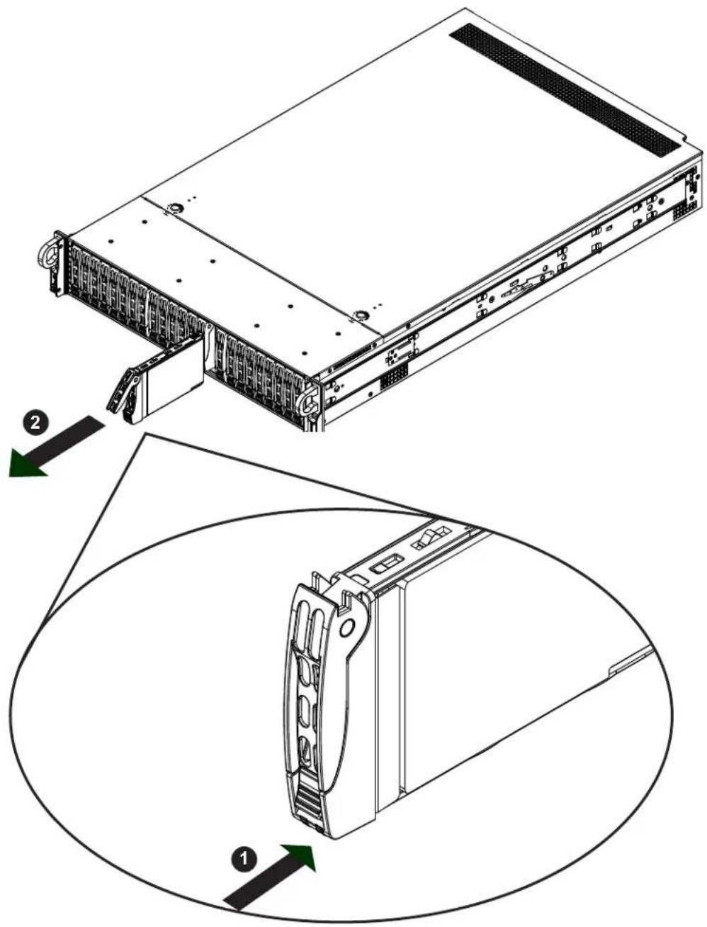
text_image
Technical diagram of a server rack with labeled components and directional arrows indicating assembly steps.Figure 3-4. Removing a Drive Carrier
Installing a Drive
- Remove the dummy drive, which comes pre-installed in the drive carrier, by removing the screws securing the dummy drive to the carrier. These screws are not used to mount the actual drive.

text_image
01-8888888-XXD 01-8888888-XXDFigure 3-5. Removing the Dummy Drive from a Carrier
- Insert a drive into the carrier with the PCB side facing down and the connector end toward the rear of the carrier. Align the drive in the carrier so that the screw holes line up. Note that there are holes in the carrier marked "SATA" to aid in correct installation.
- Secure the drive to the carrier with four M3 screws as illustrated below. These screws are included in the chassis accessory box.
- Insert the drive carrier with the disk drive into its bay, keeping the carrier oriented so that the hard drive is on the top of the carrier and the release button is on the right side. When the carrier reaches the rear of the bay, the release handle will retract.
- Push the handle in until it clicks into its locked position
Hot-Swap for NVMe Drives
Supermicro Ultra servers support NVMe surprise hot-swap. For even better data security, NVMe orderly hot-swap is recommended. NVMe drives can be ejected and replaced remotely using IPMI.
Note: If you are using VROC, see the VROC appendix in this manual instead.
Ejecting a Drive
- IPMI > Server Health > NVMe SSD
- Select Device, Group and Slot, and click Eject. After ejecting, the drive Status LED indicator turns green.
- Remove the drive.
Note that Device and Group are categorized by the CPLD design architecture. The 2029U-T Series server has one Device and one Group, except the 2029U-TN24 server which has one Device and two Groups.
Slot is the slot number on which the NVMe drives are mounted.

text_image
Host Identification Server: 172.031.048.114 User: ADMIN (Administrator) System Server Health Configuration Remote Control Virtual Media Maintenance Miscellaneous Help Server Health Sensor Readings Health Event Log Power Consumption Power Source NVMe SSD NVMe SSD This page displays NVMe SSD information. Locate / Stop Locate SSD Devices:0 Groucp0 Slot:9 Locate Stop Locate End CPLD / BPN ID: EF Rev: 10 Slot:0 Status Present Temperature 35 degrees C Vendor ID 80.86 Serial Number BTLF7270687N4P0IGN Model Number INTEL SSDPE2X040T7 Slot:1 Status Present Temperature 33 degrees C Vendor ID 80.86 Serial Number PHLF729690684P0IGN Model Number INTEL SSDPE2X040T7 Slot:2 Copyright © 2016 Topo Micro Computer, Inc.Figure 3-6. IPMI Screenshot
Replacing the Drive
- Insert the replacement drive.
- IPMI > Server Health > NVMe SSD
- Select Device, Group and slot and click Insert. The drive Status LED indicator flashes red, then turns off. The Activity LED turns blue.
Checking the Temperature of an NVMe Drive
There are two ways to check using IPMI.
Checking a Drive
- IPMI > Server Health > NVMe SSD – Shows the temperatures of all NVMe drives, as in Figure 3-4.
- IPMI > Server Health > Sensor Reading > NVME_SSD – Shows the single highest temperature among all the NVMe drives.
M.2 Solid State Drives (with optional riser card)
Up to two M.2 solid state drives (SSDs) can be installed on the optional RSC-UMR-8 riser card, with some restrictions. One M.2 socket supports PCI-E and one supports SATA.
Several SSD lengths are supported—42mm, 60mm 80mm or 110mm. For each length, there is an hole in the storage adapter card for a plastic standoff. The following combinations are supported:
- Two 42 or 60 ~mm
• One 42 and one 80 mm - One 110 ~mm

text_image
M1.2 SATA DESIGNED IN USA Holes for Standoffs (choose one or two) BAR CODE SSD SATA Socket SSD PCI-E Socket RSC-UMR-8REV-1.06 SLOT1 PCI-E 3.0 X8 SUPERO® FEFigure 3-7. M.2 SSDs on the Riser Card
If using the M.2 SATA socket, connect the optional cable, CBL-SAST-0538, to the motherboard at connectors S-SATA4 or S-SATA5.
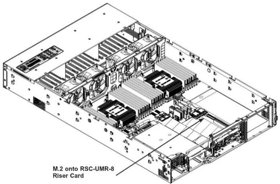
text_image
M.2 onto RSC-UMR-8 Riser CardFigure 3-8. M.2 SSDs on a Riser Card
Installing an M.2 SSD
Caution: Use industry-standard anti-static equipment, such as gloves or wrist strap, and follow precautions to avoid damage caused by ESD.
Locate the RSC-UMR-8 storage adapter card in the SXB2 slot on the motherboard. There is a plastic standoff in one of the holes. If it is the correct hole for your M.2 SSD, you can slide the SSD into the socket, and secure it by pushing the plug into the standoff.
If the plastic standoff not in the correct hole, or if you want to install two M.2 SSDs, you must remove the storage adapter card to move or add the standoff.
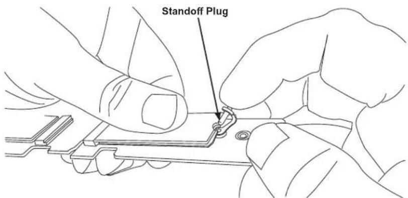
text_image
Standoff PlugFigure 3-9. Inserting the Standoff Plug
(Note: Your card looks different, but the standoff functions the same.)
Removing the Storage Adapter Card to Mount M.2 SSDs
- Remove the left WIO riser card as described in Figure 3-16.
- Remove the screw in the small L bracket that holds the RSC-UMR-8 storage adapter card.
- Pull the RSC-UMR-8 storage adapter card out of the motherboard slot.
- Push the plastic standoffs out of the riser card. Push them into the correct holes for your SSD lengths.
- Insert the SSD into the socket on the riser card. Then push it flat against the adapter card and the plastic standoff.
- Secure the SSD by firmly inserting the standoff plug.
- Replace the RSC-UMR-8 storage adapter card and the WIO riser card.
Note: A specialized air shroud is available for cooling the M.2 SSD. See the following "System Cooling" section for instructions.
System Cooling
Fans
The chassis contains four 8-cm high-performance fans. Fan speed is controlled by IPMI depending on the system temperature. If a fan fails, the remaining fans will ramp up to full speed. The system will continue to run with a failed fan, although it may shut down if the heat gets too great. Replace any failed fan at your earliest convenience with the same model. Failed fans can be identified through the IPMI.
Changing a System Fan
- Determine which fan has failed using IPMI, or if necessary, open the chassis while the system is running. Never run the server for long without the chassis cover.
- Push the release tab and pull the failed fan from the chassis. Fans can be replaced while the system is running.
- Replace the failed fan with an identical fan, available from Supermicro. Push the new fan into the housing, making sure the air flow direction is the same.
- Power up the system and check that the fan is working properly and that the LED on the control panel has turned off. Finish by replacing the chassis cover.

text_image
Technical diagram of a server rack with numbered components for identificationFigure 3-10. Fan Positions and Numbering
Installing the Air Shrouds
Air shrouds concentrate airflow to maximize fan efficiency. They do not require screws to install. If you use an M.2 SSD, a specialized shroud is installed instead of the standard shrouds. Some GPUs require specialized shrouds (see Appendix F).
Installing the Standard Air Shrouds
- Position the air shrouds as illustrated in the figure below, sliding the front notch over the pin on the fan tray.
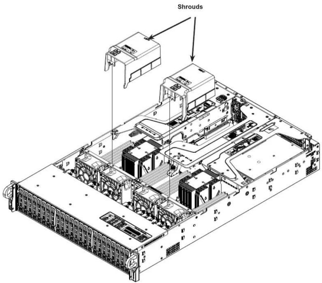
text_image
ShroudsFigure 3-11. Installing the Standard Air Shrouds
Installing a Specialized Air Shroud for M.2
- Position the air shroud as illustrated in the figure below, sliding the front notch over the pin on the fan tray.

natural_image
Technical line drawings of an internal server or rack system with labeled components (no text or symbols present)Figure 3-12. Installing the M.2 Air Shroud
Checking the Server Air Flow
• Make sure there are no objects to obstruct airflow in and out of the server.
- Do not operate the server without drives or drive carriers in the drive bays.
• Use only recommended server parts.
- Make sure no wires or foreign objects obstruct air flow through the chassis. Pull all excess cabling out of the airflow path or use shorter cables.
The control panel LEDs display system heat status. See "Control Panel" in Chapter 1 for details.
Overheating
There are several possible responses if the system overheats.
- Use the LEDs to determine the nature of the overheating condition.
- Confirm that the chassis covers are installed properly.
• Make sure all fans are present and operating normally. - Check the routing of the cables.
- Verify that the heatsinks are installed properly.
Power Supply
The system features redundant power supplies and will continue to operate if one module fails. It should be replaced as soon as convenient. They can be changed without powering down the system. New units can be ordered directly from Supermicro or authorized distributors.
These power supplies are auto-switching capable. This feature enables them to automatically sense the input voltage and operate at a 100-120v or 180-240v.
Power Supply LEDs
On the rear of the power supply module, an LED displays the status.
• Solid Green: When illuminated, indicates that the power supply is on.
- Blinking Green: When blinking, indicates that the power supply is plugged in and turned off by the system.
- Blinking Amber: When blinking, indicates that the power supply has a warning condition and continues to operate.
- Solid Amber: When illuminated, indicates that the power supply is plugged in, and is in an abnormal state. The system might need service. Please contact Supermicro technical support.
Changing the Power Supply Module:
- Unplug the AC cord from the module to be replaced.
- On the back of the module, push the release tab sideways.
- Pull the module out using the handle.

text_image
PWS1 PWS2 Release TabsFigure 3-13. Power Supply Release Tabs
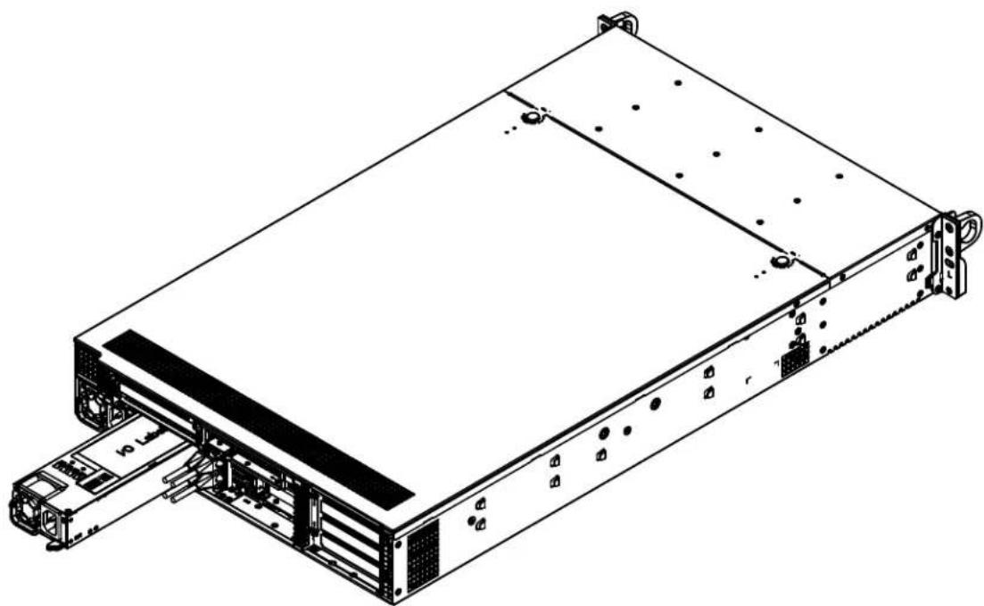
natural_image
Technical line drawing of a server rack unit with drive bays and mounting hardware (no text or symbols)Figure 3-14. Replacing the Power Supply
- Push the new power supply module into the power bay until it clicks. Replace with the same model.
- Plug the AC power cord back into the module.
PCI Expansion Cards
Riser cards on chassis brackets allow you to add PCI expansion cards. The total number of expansion cards depends on the model in the 2029U-T Series. All expansion cards are PCI-Express 3.0. For all models:
• RSC-R2UW-4E8 supports four standard size PCI-E x8 expansion cards (5-8).
• RSC-R1UW-E8R supports one low-profile x8 expansion card (4)
Additional expansion card capability depends on which Ultra riser card is installed in your model (see the table below). For details on installing GPUs, see Appendix F.
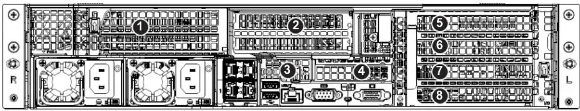
text_image
Diagram of an internal server rack with numbered components and labeled portsFigure 3-15. PCI Expansion Card Chassis Slots
| Expansion Card Configurations | |||
| Slot | Mechanical Electrical In Models | ||
| 1 | Double-width, full-height, full-length x16 (CPU1) All models | ||
| 2 | Double-width, full-height, full-length | x16 (CPU1)x8 (CPU1) | TR4TAll other models |
| 3 | Internal low-profile, half-length | NAx8 (CPU1) | TR4TAll other models |
| 4 | Low-profile, half-length x8 (CPU2) All models | ||
| 5 | Full-height, full-length x8 (CPU2) All modes | ||
| 6 | Full-height, full-length x8 (CPU2) All modes | ||
| 7 | Full-height, full-length x8 (CPU2) All modes | ||
| 8 | Full-height, full-length x8 (CPU2) All modes | ||
Full-height = 4.2", Low-profile = 2.5" Full-length = 10.5", Half-length = 6.6"
* This slot supports only Supermicro SAS Cards listed below.
| Supermicro SAS Cards | |
| Part Number Description | |
| AOC-S3008L-L8e(8-port HBA) | Std LP, 8 internal ports, 12 Gb/s per port, Gen 3, 122HDD, HBA |
| AOC-S3008L-L8i(8-port SW RAID) | Std LP, 8 internal ports, 12 Gb/s per port, Gen 3, 63HDD, RAID 0, 1, 1E |
| AOC-S3108L-H8iR(8-port HW RAID) | Std LP, 8 internal ports, 12 Gb/s per port, Gen 3, 240HDD, RAID 0, 1, 5, 6, 10, 50, 60 |
| AOC-S3108L-H8iR-16DD(8-port HW RAID) | Std LP, 8 internal ports, 12 Gb/s per port, Gen 3, 16HDD, RAID 0, 1, 5, 6, 10, 50, 60 |
Installing Full Height Expansion Cards
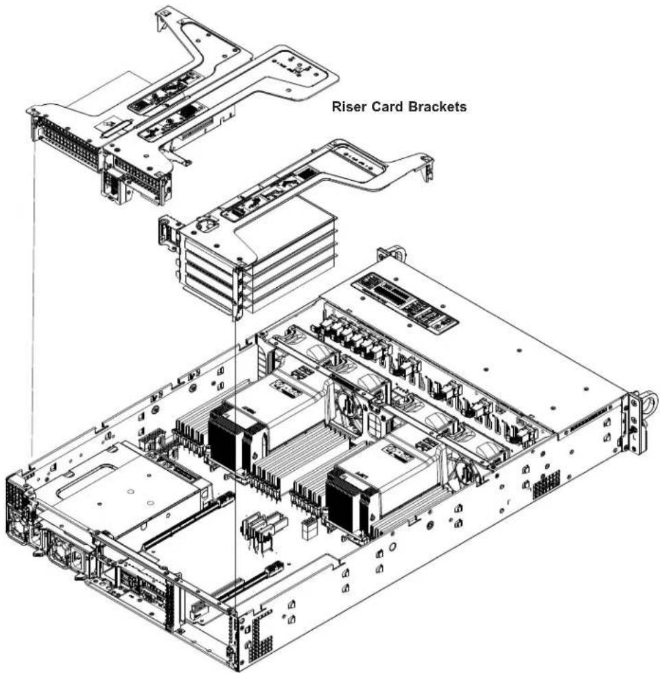
text_image
Riser Card BracketsFigure 3-16. Installing Expansion Cards
Installing PCI Expansion Cards
- Power down the system and remove the top chassis cover.
- Remove the riser card bracket, pictured above. On the rear of the chassis, each bracket is secured by a small black plastic flip-lever with an arrow on it. Flip open the appropriate lever to release the bracket, then pull the bracket out of the chassis.
- Insert the expansion card(s) into the riser card slot(s) while aligning the rear PCI shield.
- Replace the riser card into the motherboard expansion slot while aligning the bracket into the chassis. Flip the black plastic lever back in place, making sure it snaps closed with a click.
- Replace the chassis cover.
Installing the Low Profile Center Expansion Card

text_image
Riser Card SlotFigure 3-17. Installing Low Profile Expansion Card
Installing the Low Profile PCI Expansion Card (4)
- Power down the system and remove the top chassis cover.
- If necessary, remove the full height expansion card to access the low profile riser card slot, pictured above.
- Insert the expansion card into the riser card slot while aligning the rear PCI shield into the chassis. Add the screw to secure the PCI shield.
- Replace the full height expansion card above the low profile card if necessary, then replace the chassis cover.
Installing the Internal Expansion Card
For most models, the Ultra riser card that holds the LAN ports also offers another internal low profile card slot (③). Installation is pictured below.

text_image
View from Front of Chassis Thumb Screw to Secure Bracket Internal Expansion Card View from Rear of ChassisFigure 3-18. Ultra Riser Bracket and Expansion Cards
See previous procedures for details to access the riser card and bracket.
Ultra Riser and Expansion Cards with Optional Storage Drives
This server supports an option to add two storage drives in place of expansion cards.
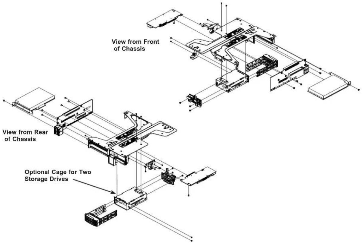
text_image
View from Front of Chassis View from Rear of Chassis Optional Cage for Two Storage DrivesFigure 3-19. Ultra Riser and Expansion Cards with Optional Storage Drives
Chapter 4
Motherboard Connections
This section describes the connections on the motherboard and provides pinout definitions.
Note that depending on how the system is configured, not all connections are required.
The LEDs on the motherboard are also described here. A motherboard layout indicating component locations may be found in Chapter 1.
Please review the Safety Precautions in Appendix B before installing or removing components.
4.1 Power Connections
Two power connections supply the motherboard and several more supply for onboard devices.
Main Power Connector
Two proprietary main power headers are located at PSU1 and PSU2. Connect appropriate power supply units to these two headers to provide adequate power to your system.
Important: To provide adequate power to the motherboard, connect the both main power connectors to the power supply. Failure to do so may void the manufacturer's warranty on your power supply and motherboard.
Backplane Power Connectors & GPU Power Connectors
In addition to the main power headers, eight 8-pin power connectors are also located on the motherboard to supply power to onboard devices. GPU Power Connectors 1-4 are used for GPU devices, while BP PWR 1-4 are used for backplane devices. Connect these connectors to your power supply to provide adequate power to your onboard devices.
| 8-pin GPU Power Pin Definitions | |
| Pin# | Definition |
| 1 - 4 | Ground |
| 5 - 8 | +12 V |
| 8-pin Backplane Power Pin Definitions | |
| Pin# Definition | |
| 1 - 4 Ground | |
| 5 - 6 +12V | |
| 7 - 8 +5V |
4.2 Headers and Connectors
Fan Headers
There are eight fan headers on the motherboard. These are 4-pin fan headers, although pins 1-3 are backward compatible with traditional 3-pin fans. Four-pin fans allow fan speeds to be controlled by Thermal Management in IPMI. When using the Thermal Management setting, use all 3-pin fans or all 4-pin fans.
| Fan HeaderPin Definitions | |
| Pin# | Definition |
| 1 | Ground (Black) |
| 2 | +12V (Red) |
| 3 | Tachometer |
| 4 | PWM Control |
T-SGPIO3 Header
A Serial General Purpose Input/Output header (T-SGPIO3) is located next to the TPM/Port 80 on the motherboard. This header is used to communicate with the enclosure management chip on the backplane.
| SGPIO HeaderPin Definitions | |||
| Pin# Definition Pin# Definition | |||
| 1 NC 2 NC | |||
| 3 Ground 4 DATA | Out | ||
| 5 Load 6 Ground | |||
| 7 Clock 8 NC | |||
| NC = No Connection | |||
Disk-On-Module Power Connector
The Disk-On-Module (DOM) power connectors at JSD1 and JSD2 provide 5V power to a solid-state DOM storage devices connected to one of the SATA ports.
| DOM Power Pin Definitions | |
| Pin# Definition | |
| 1 5V | |
| 2 Ground | |
| 3 Ground | |
TPM Header
The JTPM1 header is used to connect a Trusted Platform Module (TPM)/Port 80, which is available from Supermicro. A TPM/Port 80 connector is a security device that supports encryption and authentication in hard drives. It allows the motherboard to deny access if the TPM associated with the storage drive is not installed in the system.
| Trusted Platform Module/Port 80 Header Pin Definitions | ||
| Pin# Definition Pin# Definition | ||
| 1 P3V3 2 SPI_TPM_CS_N | ||
| 3 PCI-E_RESET_N# 4 SPI_PCH_MISO | ||
| 5 SPI_PCH_CLK# 6 Ground | ||
| 7 SPI_PCH_MOSI 8 N/A | ||
| 9 JTPM1_P3V3A 10 IRQ_TPM_SPIN_N | ||
Internal Speaker/Buzzer
The Internal Speaker/Buzzer (SP1) is used to provide audible indications for various beep codes.
| Internal BuzzerPin Definitions | ||
| Pin# Definition | ||
| 1 Pos | (+) Beep In | |
| 2 Neg | (-) Alarm Speaker | |
4-pin BMC External I²C Header
A System Management Bus header for IPMI 2.0 is located at JIPMB1. Connect a cable to this header to use the IPMB I ^2 C connection on your system..
| External I2C Header Pin Definitions | |
| Pin# | Definition |
| 1 | Data |
| 2 | Ground |
| 3 | Clock |
| 4 | No Connection |
Chassis Intrusion
A Chassis Intrusion header is located at JL1 on the motherboard. Attach the appropriate cable from the chassis to the header to inform you when the chassis is opened.
| Chassis Intrusion Pin Definitions | |
| Pins Definition | |
| 1 Intrusion Input | |
| 2 Ground |
RAID Key Header
A RAID Key header is located at JRK1 on the motherboard. It supports VMD used in creating optional advanced NVMe RAID configurations.
| RAID Key HeaderPin Definitions |
| Pin# Definition |
| 1 Ground |
| 2 RAID_KEY_PU |
| 3 Ground |
| 4 PCH_RAID_KEY |
Front VGA Port
One VGA port is located at JVGA2 on the motherboard. This VGA port provides front accessible video display.
Micro SD Card Slot
JSDCARD1: Micro SSD card slot (reserved for manufacture use only).
NVMe SMBus Headers
NVMe SMBus (I²C) headers (JNVI²C1/2), used for PCI-E SMBus clock and data connections, provide hot-plug support through a dedicated SMBus interface. This feature is only available for a Supermicro complete system with a proprietary NVMe add-on card and cable installed.
| NVMe SMBus Header Pin Definitions | |
| Pin# | Definition |
| 1 | Data |
| 2 | Ground |
| 3 | Clock |
| 4 | VCCIO |
Control Panel
JF1 contains header pins for various control panel connections. See the figure below for the pin locations and definitions of the control panel buttons and LED indicators.
All JF1 wires have been bundled into a single cable to simplify this connection. Make sure the red wire plugs into pin 1 as marked on the motherboard. The other end connects to the control panel PCB board.
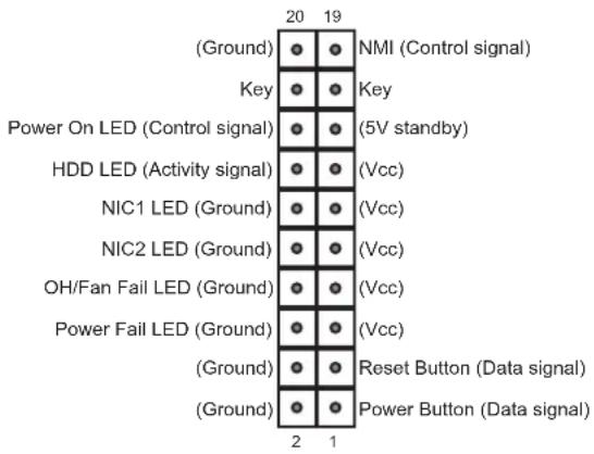
text_image
(Ground) Key Power On LED (Control signal) HDD LED (Activity signal) NIC1 LED (Ground) NIC2 LED (Ground) OH/Fan Fail LED (Ground) Power Fail LED (Ground) (Ground) (Ground) NMI (Control signal) Key (5V standby) (Vcc) (Vcc) (Vcc) (Vcc) Reset Button (Data signal) Power Button (Data signal)Figure 4-1. JF1 Control Panel Pins
Power Button
The Power Button connection is located on pins 1 and 2 of JF1. Momentarily contacting both pins will power on/off the system. This button can also be configured to function as a suspend button (with a setting in the BIOS - see Chapter 6). To turn off the power when the system is in suspend mode, press the button for 4 seconds or longer.
| Power ButtonPin Definitions (JF1) |
| Pin# Definition |
| 1 Signal |
| 2 Ground |
Reset Button
The Reset Button connection is located on pins 3 and 4 of JF1. Attach it to a hardware reset switch on the computer case.
| Reset ButtonPin Definitions (JF1) |
| Pin# Definition |
| 3 Reset |
| 4 Ground |
Power Fail LED
The Power Fail LED connection is located on pins 5 and 6 of JF1.
| Power Fail LEDPin Definitions (JF1) | |
| Pin# Definition | |
| 5 3.3V | |
| 6 PWR Supply Fail | |
Overheat (OH)/Fan Fail
Connect an LED cable to pins 7 and 8 of JF1 to use the Overheat/Fan Fail LED connections. The LED on pin 8 provides warnings of overheat or fan failure.
| OH/Fan Fail Indicator Status | |
| Status Definition | |
| Off Normal | |
| On Overheat | |
| Flashing Fan Fail | |
| OH/Fan Fail LEDPin Definitions (JF1) | |
| Pin# Definition | |
| 7 Blue | LED |
| 8 OH/Fan Fail LED | |
The NIC (Network Interface Controller) LED connection for LAN port 1 is located on pins 11 and 12 of JF1, and the LED connection for LAN Port 2 is on Pins 9 and 10. Attach the NIC LED cables here to display network activity.
| LAN1/LAN2 LEDPin Definitions (JF1) | |
| Pin# | Definition |
| 9 | NIC2 Activity LED |
| 10 | NIC2 Link LED |
| 11 | NIC1 Activity LED |
| 12 | NIC1 Link LED |
HDD LED/UID Switch
The HDD LED/UID Switch connection is located on pins 13 and 14 of JF1. Attach a cable to Pin 14 to show hard drive activity status. Attach a cable to Pin 13 to use UID switch. Refer to the table below for pin definitions.
| HDD LEDPin Definitions (JF1) | |
| Pin# Definition | |
| 13 3.3V Standby/UID Switch | |
| 14 HDD Active |
Power LED
The Power LED connection is located on pins 15 and 16 of JF1.
| Power LEDPin Definitions (JF1) |
| Pin# Definition |
| 15 3.3V |
| 16 Power LED |
NMI Button
The non-maskable interrupt button header is located on pins 19 and 20 of JF1.
| NMI ButtonPin Definitions (JF1) |
| Pin# Definition |
| 19 Control |
| 20 Ground |
4.3 Input/Output Ports
Rear I/O Ports
See the figure below for the locations and descriptions of the I/O ports on the rear of the motherboard.
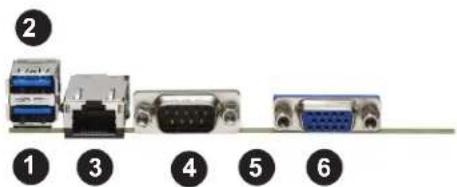
text_image
② ① ③ ④ ⑤ ⑥Figure 4-2. Rear I/O Ports
| Rear I/O Ports | |
| # Description | |
| 1. USB 0 (3.0) | |
| 2. USB 1 (3.0) | |
| 3. IPMI Dedicated LAN | |
| 4. COM Port 1 | |
| 5. UID switch/LED (not pictured) | |
| 6. VGA |
LAN Ports
There are two or four LAN ports on the chassis rear provided by the Ultra add-on card, depending on the model. There is also a dedicated IPMI LAN port on the I/O back panel. For more information on IPMI, refer to the IPMI User's Guide posted on our website at http://www.supermicro.com.
Unit Identifier Switch/UID LED Indicator
A Unit Identifier (UID) switch and a UID LED indicator are located on the rear of the system. When you press the UID switch, both front and rear UID LED indicators are toggled on or off. The UID indicators provide easy identification of a system in a rack.
Note: UID can also be triggered using IPMI.
4.4 Jumpers
Explanation of Jumpers
To modify the operation of the motherboard, jumpers are used to choose between optional settings. Jumpers create shorts between two pins to change the function associated with it. Pin 1 is identified with a square solder pad on the printed circuit board. See the motherboard layout page for jumper locations.
Note: On a two-pin jumper, "Closed" means the jumper is on both pins and "Open" indicates the jumper is either on only one pin or has been completely removed.
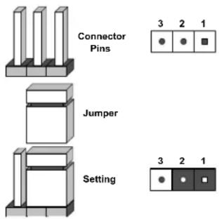
text_image
Connector Pins Jumper Setting 3 2 1 ● ● ■ 3 2 1CMOS Clear
JBT1 is used to clear CMOS, which will also clear any passwords. Instead of pins, this jumper consists of contact pads to prevent accidentally clearing the contents of CMOS.
To Clear CMOS
- First power down the system and unplug the power cord(s).
- Remove the cover of the chassis to access the motherboard.
- Remove the onboard battery from the motherboard.
- Short the CMOS pads with a metal object such as a small screwdriver for at least four seconds.
- Remove the screwdriver (or shorting device).
- Replace the cover, reconnect the power cord(s) and power on the system.
Notes: Clearing CMOS will also clear all passwords.
Do not use the PW_ON connector to clear CMOS.

JBT1 contact pads
Watch Dog
JWD controls the Watch Dog function. Watch Dog is a monitor that can reboot the system when a software application hangs. Jumping pins 1-2 will cause Watch Dog to reset the system if an application hangs. Jumping pins 2-3 will generate a non-maskable interrupt signal for the application that hangs. Watch Dog must also be enabled in BIOS.
The default setting is Reset.
Note: When Watch Dog is enabled, the user needs to write their own application software to disable it.
| Watch DogJumper Settings | |
| Jumper Setting Definition | |
| Pins 1-2 Reset | |
| Pins 2-3 NMI | |
| Open Disabled | |
I²C Bus for VRM
Jumpers JVRM1 and JVRM2 allow the BMC or the PCH to access CPU and memory VRM controllers. See the table below for jumper settings.
| VRMJumper Settings | |
| Jumper Setting Definition | |
| Pins 1-2 BMC (Normal) | |
| Pins 2-3 PCH | |
4.5 LED Indicators
LAN LEDs
The Ethernet ports each have two LEDs. One LED indicates activity when flashing, while the other LED may be green, amber or off to indicate the speed of the connection.
| LAN LED(Connection Speed Indicator) | |
| LED Color Definition | |
| Off 10 Mb/s | |
| Green 100 Mb/s | |
| Amber 1 Gb/s | |
IPMI-Dedicated LAN LEDs
A dedicated IPMI LAN port is also included on the motherboard. The amber LED on the right of the IPMI LAN port indicates activity, while the green LED on the left indicates the speed of the connection.
| IPMI LAN LED | |
| Color Definition | |
| Off No Connection | |
| Green 100 Mb/s |
Unit ID LED
A rear unit identifier (UID) indicator at LED1 is located near the UID switch on the I/O back panel. It provides easy identification of a unit that may need service.
Onboard Power LED
LEDPWR is an Onboard Power LED. When this LED is lit, it means power is present on the motherboard. In suspend mode this LED will blink on and off. Be sure to turn off the system and unplug the power cord(s) before removing or installing components
| Onboard Power LED Indicator | |
| LED Color Definition | |
| Off | System Off (power cable not connected) |
| Green System | On |
BMC Heartbeat LED
LEDM1 is the BMC heartbeat LED. When the LED is blinking green, BMC is functioning normally.
| Onboard Power LED Indicator | |
| LED Color Definition | |
| Green:Blinking | BMC Normal |
Memory Fault Indication LEDs
The memory fault LEDs provide visual notification to a service technician which memory DIMM slot(s) are at fault due to un-correctable memory errors during POST (Power-On Self-Test). A memory fault LED will remain "on" even after system reboots (or repeated "power cycling") until it is reset manually by the technician using the BIOS setup menu to turn it off. This feature allows the technician to easily identify and replace any bad DIMMs that may be at fault in the system.
| Memory Fault LED Indicators | |
| LED Description Status | |
| LED_P1_A1-A2 Memory Fault LEDs for Memory Module P1_A1-A2 Red: on (memory errors) | |
| LED_P1_B1-B2 Memory Fault LEDs for Memory Module P1_B1-B2 Red: on (memory errors) | |
| LED_P1_C1-C2 Memory Fault LEDs for Memory Module P1_C1-C2 Red: on (memory errors) | |
| LED_P1_D1-D2 Memory Fault LEDs for Memory Module P1_D1-D2 Red: on (memory errors) | |
| LED_P1_E1-E2 Memory Fault LEDs for Memory Module P1_E1-E2 Red: on (memory errors) | |
| LED_P1_F1-F2 Memory Fault LEDs for Memory Module P1_F1-F2 Red: on (memory errors) | |
| LED_P2_A1-A2 Memory Fault LEDs for Memory Module P2_A1-A2 Red: on (memory errors) | |
| LED_P2_B1-B2 Memory Fault LEDs for Memory Module P2_B1-B2 Red: on (memory errors) | |
| LED_P2_C1-C2 Memory Fault LEDs for Memory Module P2_C1-C2 Red: on (memory errors) | |
| LED_P2_D1-D2 Memory Fault LEDs for Memory Module P2_D1-D2 Red: on (memory errors) | |
| LED_P2_E1-E2 Memory Fault LEDs for Memory Module P2_E1-E2 Red: on (memory errors) | |
| LED_P2_F1-F2 Memory Fault LEDs for Memory Module P2_F1-F2 Red: on (memory errors) |
4.6 Storage Ports
I-SATA 3.0 and S-SATA 3.0 Ports
The X11DPU has eight I-SATA 3.0 ports (I-SATA0-3, I-SATA4-7) which are supported by the Intel C621 chipset. In addition, it also has six S-SATA 3.0 ports (S-SATA0-3, S-SATA4/S-SATA5) that are supported by the Intel SCU. S-SATA4/5 can be used with Supermicro SuperDOMs which are yellow SATA DOM connectors with power pins built in, and do not require external power cables. Supermicro SuperDOMs are backward-compatible with regular SATA HDDs or SATA DOMs that need external power cables.
NVM Express Connections
Four NVM Express ports are located on the motherboard. These NVMe ports provide PCI-E 3.0 x4 connections. P1_NVME0/1 are supported by CPU1. P2_NVME0/1 are supported by CPU2. The NVMe ports provide high-speed low-latency connections directly from the CPU to NVMe Solid State drives (SSDs). This greatly increases SSD data-throughput performance and significantly reduces PCI-E latency by simplifying driver/software requirements resulting from direct PCI-E interface from the CPU to the NVMe SSD drives.
Chapter 5
Software
After the hardware has been installed, you can install the Operating System (OS), configure RAID settings and install the drivers.
5.1 Microsoft Windows OS Installation
If you will be using RAID, you must configure RAID settings before installing the Windows OS and the RAID driver. Refer to the RAID Configuration User Guides posted on our website at www.supermicro.com/support/manuals.
Installing the OS
- Create a method to access the MS Windows installation ISO file. That can be a USB flash or media drive.
- Retrieve the proper RST/RSTe driver. Go to the Supermicro web page for your motherboard and click on "Download the Latest Drivers and Utilities", select the proper driver, and copy it to a USB flash drive.
- Boot from a bootable device with Windows OS installation. You can see a bootable device list by pressing F11 during the system startup.
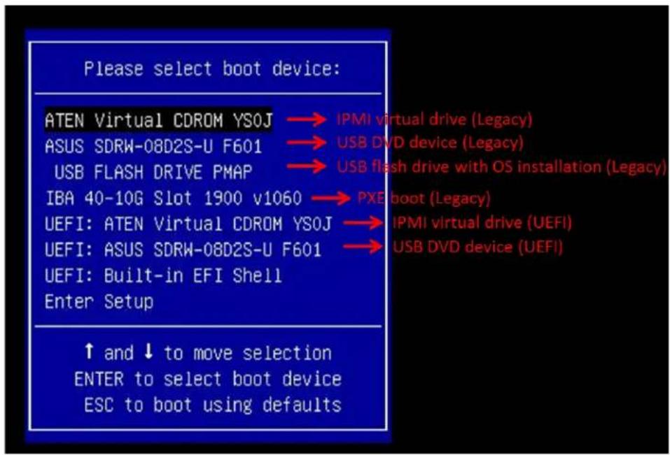
text_image
Please select boot device: ATEN Virtual CDROM YSOJ → IPMI virtual drive (Legacy) ASUS SDRW-08D2S-U F601 → USB DVD device (Legacy) USB FLASH DRIVE PMAP → USB flash drive with OS installation (Legacy) IBA 40-10G Slot 1900 v1060 → PXE boot (Legacy) UEFI: ATEN Virtual CDROM YSOJ → IPMI virtual drive (UEFI) UEFI: ASUS SDRW-08D2S-U F601 → USB DVD device (UEFI) UEFI: Built-in EFI Shell Enter Setup ↑ and ↓ to move selection ENTER to select boot device ESC to boot using defaultsFigure 5-1. Select Boot Device
- During Windows Setup, continue to the dialog where you select the drives on which to install Windows. If the disk you want to use is not listed, click on "Load driver" link at the bottom left corner.

text_image
Where do you want to install Windows? Name Total size Free space Type Refresh Delete Format New Load driver Extend We couldn't find any drives. To get a storage driver, click Load driver. NextFigure 5-2. Load Driver Link
To load the driver, browse the USB flash drive for the proper driver files.
- For RAID, choose the SATA/sSATA RAID driver indicated then choose the storage drive on which you want to install it.
-
For non-RAID, choose the SATA/sSATA AHCI driver indicated then choose the storage drive on which you want to install it.
-
Once all devices are specified, continue with the installation.
- After the Windows OS installation has completed, the system will automatically reboot multiple times.
5.2 Driver Installation
The Supermicro website contains drivers and utilities for your system at https://www.supermicro.com/wdl/driver. Some of these must be installed, such as the chipset driver.
After accessing the website, go into the CDR_Images (in the parent directory of the above link) and locate the ISO file for your motherboard. Download this file to a USB flash or media drive. (You may also use a utility to extract the ISO file if preferred.)
Another option is to go to the Supermicro website at http://www.supermicro.com/products/. Find the product page for your motherboard, and "Download the Latest Drivers and Utilities". Insert the flash drive or disk and the screenshot shown below should appear.

text_image
SUPERMICRO X11DPU Motherboard Drivers & Tools (Win7) SUPERMICRO Drivers & Tools Intel C620 Chipset X11 DPU SUPERMICRO Computer Inc. Intel Chipset INF files Microsoft Net Framework (Optional) ASPEED Graphics Driver Intel Rapid Storage Technology Enterprise Intel USB 3.0 Drivers Intel PRO Network Connections Drivers Intel Management Engine SUPERMICRO SuperDoctor 5 Build driver diskettes and manuals Browse CD Auto Start Up Next TimeFigure 5-3. Driver & Tool Installation Screen
Note: Click the icons showing a hand writing on paper to view the readme files for each item. Click the computer icons to the right of these items to install each item (from top to the bottom) one at a time. After installing each item, you must re-boot the system before moving on to the next item on the list. The bottom icon with a CD on it allows you to view the entire contents.
5.3 SuperDoctor® 5
The Supermicro SuperDoctor 5 is a program that functions in a command-line or web-based interface for Windows and Linux operating systems. The program monitors such system health information as CPU temperature, system voltages, system power consumption, fan speed, and provides alerts via email or Simple Network Management Protocol (SNMP).
SuperDoctor 5 comes in local and remote management versions and can be used with Nagios to maximize your system monitoring needs. With SuperDoctor 5 Management Server (SSM Server), you can remotely control power on/off and reset chassis intrusion for multiple systems with SuperDoctor 5 or IPMI. SuperDoctor 5 Management Server monitors HTTP, FTP, and SMTP services to optimize the efficiency of your operation.
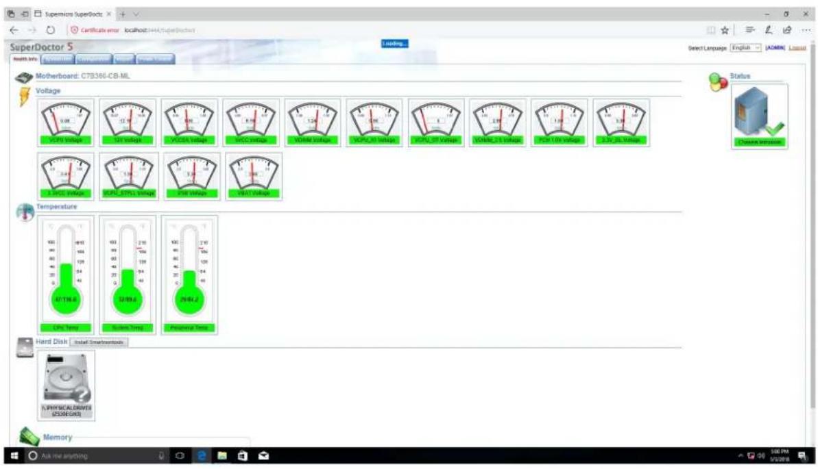
text_image
SuperDoctor 5 Matherboard: C7B366-CB-ML Voltage 10V 20V 30V 40V 50V 60V 70V 80V 90V 100V 110V 120V 130V 140V 150V 160V 170V 180V 190V 200V 210V 220V 230V 240V 250V 260V 270V 280V 290V 300V 310V 320V 330V 340V 350V 360V 370V 380V 390V 400V 410V 420V 430V 440V 450V 460V 470V 480V 490V 500V 510V 520V 530V 540V 550V 560V 570V 580V 590V 600V 610V 620V 630V 640V 650V 660V 670V 680V 690V 700V 710V 720V 730V 740V 750V 760V 770V 780V 790V 800V 810V 820V 830V 840V 850V 860V 870V 880V 890V 900V 910V 920V 930V 940V 950V 960V 970V 980V 990V 1000V 1010V 1020V 1030V 1040V 1050V 1060V 1070V 1080V 1090V 1100V 1110V 1120V 1130V 1140V 1150V 1160V 1170V 1180V 1190V 1200V 1210V 1220V 1230V 1240V 1250V 1260V 1270V 1280V 1290V 1300V 1310V 1320V 1330V 1340V 1350V 1360V 1370V 1380V 1390V 1400VFigure 5-4. SuperDoctor 5 Interface Display Screen (Health Information)
5.4 BMC
The motherboard provides remote access, monitoring and management through the baseboard management controller (BMC) and other management controllers distributed among different system modules. There are several BIOS settings that are related to BMC. For general documentation and information on BMC, visit our website at:
www.supermicro.com/en/solutions/management-software/bmc-resources
BMC ADMIN User Password
For security, each system is assigned a unique default BMC password for the ADMIN user. This can be found on a sticker on the chassis and a sticker on the motherboard. The sticker also displays the BMC MAC address. If necessary, the password can be reset using the Supermicro IPMICFG tool.

text_image
BMC AC1F6BC07014 PWD SUOKJKJYZCFigure 5-5. BMC Password Label
See Chapter 1 for the locations of the labels.
Chapter 6
UEFI BIOS
6.1 Introduction
This chapter describes the AMI UEFI BIOS setup utility for the X11DPU and provides the instructions on navigating the setup screens. The BIOS is stored in a Flash EEPROM and can be updated.
Note: Due to periodic changes to the BIOS, some settings may have been added or deleted since this manual was published.
Starting BIOS Setup Utility
To enter the BIOS setup utility screens, press the
The BIOS screens have three main frames. The large left frame displays options can be configured by the user. These are blue. When an option is selected, it is highlighted in white. Settings printed in Bold are the default values.
In the left frame, a "▶" indicates a submenu. Highlighting such an item and pressing the
The upper right frame displays helpful information for the user. The AMI BIOS has default informational messages built in. The manufacturer retains the option to include, omit, or change any of these informational messages.
The lower right frame lists navigational methods. The AMI BIOS setup utility uses a key-based navigation system called hot keys. Most of these hot keys can be used at any time during setup navigation. These keys include
Some system parameters may be changed.
6.2 Main Setup
When running the BIOS setup utility, it starts with the Main screen. You can always return to it by selecting the Main tab on the top of the screen.
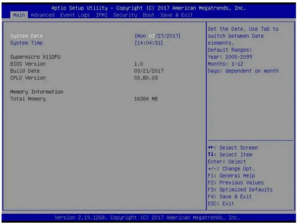
text_image
Aptio Setup Utility - Copyright (C) 2017 American Megatrends, Inc. Main Advanced Event Logs IPMI Security Boot Save & Exit System Date [Mon 03/27/2017] System Time [14:04:31] Supermicro X11DPU BIOS Version 1.0 Build Date 03/21/2017 CPLD Version 03.80.03 Memory Information Total Memory 16384 MB Set the Date. Use Tab to switch between Date elements. Default Ranges: Year: 2005-2099 Months: 1-12 Days: dependent on month +: Select Screen ↑↓: Select Item Enter: Select +/-: Change Opt. F1: General Help F2: Previous Values F3: Optimized Defaults F4: Save & Exit ESC: Exit Version 2.19.1268. Copyright (C) 2017 American Megatrends, Inc.The Main tab page allows you to set the date and time, and it displays system information.
System Date/System Time
Use this option to change the system date and time. Highlight System Date or System Time using the arrow keys. Enter new values using the keyboard. Press the
Note: The time is in the 24-hour format. For example, 5:30 P.M. appears as 17:30:00. The date's default value is 01/01/2016 after RTC reset.
Supermicro X11DPU (Motherboard model)
BIOS Version
Build Date (of the BIOS)
CPLD (Complex Programmable Logic Device) Version: This item displays the CPLD version used in the system.
Memory Information
Total Memory (for the system)
6.3 Advanced Setup Configurations
Use the arrow keys to select the Advanced tab and press
| Aptio Setup Utility - Copyright (C) 2019 American Megatrends, Inc. Main Advanced Event Logs IPMI Security Boot Save & Exit | |
| Boot Feature CPU Configuration Chipset Configuration Server ME Information PCH SATA Configuration PCH SSATA Configuration PCIe/PCI/PnP Configuration Super IO Configuration Serial Port Console Redirection ACPI Settings Trusted Computing HTTP BOOT Configuration TLS Authenticate Configuration ISCSI Configuration Intel(R) Optane(TM) DC Persistent Memory Configuration Driver Health | Boot Feature Configuration Page |
| ++: Select Screen ↑↓: Select Item Enter: Select +/-: Change Opt. F1: General Help F2: Previous Values F3: Optimized Defaults F4: Save & Exit ESC: Exit | |
| Version 2.20.1275. Copyright (C) 2019 American Megatrends, Inc. | |
Caution: Take caution when changing the Advanced settings. An incorrect value, a very high DRAM frequency, or an incorrect DRAM timing setting may make the system unstable. If this occurs, revert to the manufacture default settings.
▶Boot Feature
Quiet Boot
Use this feature to select the screen display between the POST messages and the OEM logo upon bootup. Select Disabled to display the POST messages. Select Enabled to display the OEM logo instead of the normal POST messages. The options are Disabled and Enabled.
Option ROM Messages
Use this feature to set the display mode for the Option ROM. Select Keep Current to display the current AddOn ROM setting. Select Force BIOS to use the Option ROM display set by the system BIOS. The options are Force BIOS and Keep Current.
Bootup NumLock State
Use this feature to set the Power-on state for the
Wait For "F1" If Error
Use this feature to force the system to wait until the 'F1' key is pressed if an error occurs. The options are Disabled and Enabled.
INT19 (Interrupt 19) Trap Response
Interrupt 19 is the software interrupt that handles the boot disk function. When this item is set to Immediate, the ROM BIOS of the host adaptors will "capture" Interrupt 19 at bootup immediately and allow the drives that are attached to these host adaptors to function as bootable disks. If this item is set to Postponed, the ROM BIOS of the host adaptors will not capture Interrupt 19 immediately and allow the drives attached to these adaptors to function as bootable devices at bootup. The options are Immediate and Postponed.
Re-try Boot
If this item is enabled, the BIOS will automatically reboot the system from a specified boot device after its initial boot failure. The options are Disabled, Legacy Boot, and EFI Boot.
Install Windows 7 USB support
Enable this feature to use the USB keyboard and mouse during the Windows 7 installation, since the native XHCI driver support is unavailable. Use a SATA optical drive as a USB drive. USB CD/DVD drives are not supported. Disable this feature after the XHCI driver has been installed in Windows. The options are Disabled and Enabled.
Port 61h Bit-4 Emulation
Select Enabled to support the emulation of Port 61h bit-4 toggling in SMM (System Management Mode). The options are Disabled and Enabled.
Power Configuration
Watch Dog Function
If enabled, the Watch Dog Timer will allow the system to reset or generate NMI based on jumper settings when it is expired for more than 5 minutes. The options are Disabled and Enabled.
Restore on AC Power Loss
Use this feature to set the power state after a power outage. Select Stay-Off for the system power to remain off after a power loss. Select Power-On for the system power to be turned on after a power loss. Select Last State to allow the system to resume its last power state before a power loss. The options are Stay Off, Power On, and Last State.
Power Button Function
This feature controls how the system shuts down when the power button is pressed. Select 4 Seconds Override for the user to power off the system after pressing and holding the power button for 4 seconds or longer. Select Instant Off to instantly power off the system as soon as the user presses the power button. The options are Instant Off and 4 Seconds Override.
Throttle on Power Fail
Throttling improves reliability and reduces power consumption in the processor via automatic voltage control during processor idle states. Select Enabled to decrease the system power by throttling CPU frequency when one power supply is failed. The options are Disabled and Enabled.
▶CPU Configuration
This submenu displays the information of the CPU as detected by the BIOS. It also allows the user to configuration CPU settings:
- Processor BSP Revision
- Processor Socket
- Processor ID
- Processor Frequency
- Processor Max Ration
- Processor Min Ration
- Microcode Revision
- L1 Cache RAM
- L2 Cache RAM
- L3 Cache RAM
- Processor 0 Version
- Processor 1 Version
Hyper-Threading [All] (Available when supported by the CPU)
Select Enabled to support Intel® Hyper-threading Technology to enhance CPU performance. The options are Disable and Enable.
Execute Disable Bit (Available if supported by the OS & the CPU)
Select Enable to enable the Execute-Disable Bit which will allow the processor to designate areas in the system memory where an application code can execute and where it cannot, thus preventing a worm or a virus from flooding illegal codes to overwhelm the processor or damage the system during an attack. (Please refer to Intel's website for more information.) The options are Disable and Enable.
Intel Virtualization Technology (Available when supported by the CPU)
Select Enable to use Intel® Virtualization Technology so that I/O device assignments will be reported directly to the VMM (Virtual Memory Management) through the DMAR ACPI Tables. This feature offers fully-protected I/O resource-sharing across the Intel® platforms, providing the user with greater reliability, security and availability in networking and data-sharing. The options are Disable and Enable.
Note: If a change is made to this setting, you will need to reboot the system for the change to take effect. Refer to Intel's website for detailed information.
PPIN Control
Select Unlock/Enable to use the Protected-Processor Inventory Number (PPIN) in the system. The options are Unlock/Disable and Unlock/Enable.
Hardware Prefetcher (Available when supported by the CPU)
If this item is set to Enable, the hardware prefetcher will prefetch streams of data and instructions from the main memory to the L2 cache to improve CPU performance. The options are Enable and Disable.
Adjacent Cache Prefetch (Available when supported by the CPU)
The CPU prefetches the cache line for 64 bytes if this feature is set to Disable. The CPU prefetches both cache lines for 128 bytes as comprised if this feature is set to Enable. The options are Enable and Disable.
DCU Streamer Prefetcher (Available when supported by the CPU)
Select Enabled to enable Intel CPU Advanced Encryption Standard (AES) Instructions for CPU to enhance data integrity. The options are Enable and Disable.
DCU IP Prefetcher (Available when supported by the CPU)
If this feature is set to Enable, the DCU (Data Cache Unit) IP prefetcher will prefetch IP addresses in advance to improve network connectivity and system performance. The options are Enable and Disable.
LLC Prefetch
Select Enable to support the LLC prefetch on all threads. The options are Disable and Enable.
Extended APIC
Select Enable to use the extended APIC (Advanced Programmable Interrupt Control) support to enhance power management. The options are Disable and Enable.
AES-NI
Select Enable to use the Intel® Advanced Encryption Standard (AES) New Instructions (NI) to ensure data security. The options are Disable and Enable.
▶Advanced Power Management Configuration
▶CPU P State Control
SpeedStep (Pstates)
EIST (Enhanced Intel® SpeedStep™ Technology) allows the system to automatically adjust processor voltage and core frequency to reduce power consumption and heat dissipation. The options are Disable and Enable.
EIST PSD Function
This feature allows the user to change the P-State (Power-Performance State) coordination type. P-State is also known as "SpeedStep" for Intel® processors. Select HW_ALL to change the P-State coordination type for all hardware components only. Select SW_ALL to change the P-State coordination type for all software installed in the system. Select SW_ANY to change the P-State coordination type for a particular software program specified by the user in the system. The options are HW_ALL, SW_ALL, and SW_ANY.
Turbo Mode (Available when Intel® EIST Technology is enabled)
Select Enable to use the Turbo Mode to boost system performance. The options are Disable and Enable.
▶Hardware PM State Control
Hardware P-States
This feature enables the hardware P-States support. The options are Disable, Native Mode, Out of Band Mode, and Native Mode with No Legacy Support.
▶CPU C State Control
Autonomous Core C-State
Use this feature to enable the autonomous core C-State control. The options are Disable and Enable.
CPU C6 report
Select Enable to allow the BIOS to report the CPU C6 State (ACPI C3) to the operating system. During the CPU C6 State, the power to all cache is turned off. The options are Disable, Enable, and Auto.
Enhanced Halt State (C1E)
Select Enable to use Enhanced Halt-State technology, which will significantly reduce the CPU's power consumption by reducing the CPU's clock cycle and voltage during a Halt-state. The options are Disable and Enable.
▶Package C State Control
Package C State
This feature allows the user to set the limit on the C-State package register. The options are C0/C1 state, C2 state, C6 (non Retention) state, C6 (Retention) state, No Limit, and Auto.
▶CPU T State Control
Software Controlled T-States
This feature enables the software controlled T-States support. The options are Disable and Enable
▶Chipset Configuration
Warning: Setting the wrong values in the following features may cause the system to malfunction.
▶ North Bridge
This feature allows the user to configure the following North Bridge settings.
▶UPI Configuration
UPI Configuration
The following information will be displayed:
- Number of CPU
- Number of IIO
- Current UPI Link Speed
• Current UPI Link Frequency
• UPI Global MMIO Low Base/Limit
• UPI Global MMIO High Base/Limit
• UPI Pci-e Configuration Base/Size
Degrade Precedence
Select Topology Precedence to degrade features if system options are in conflict. Select Feature Precedence to degrade topology if system options are in conflict. The options are Topology Precedence and Feature Precedence.
Link L0p Enable
Select Enable for the QPI to enter the L0p state for power saving. The options are Disable, Enable, and Auto.
Link L1 Enable
Select Enable for the QPI to enter the L1 state for power saving. The options are Disable, Enable, and Auto.
IO Directory Cache (IODC)
Use this feature to enable the IO Directory Cache (IODC) support. The options are Disable, Auto, Enable for Remote InvItoM Hybrid Push, InvItoM AllocFlow, Enable for Remote InvItoM Hybrid AllocNonAlloc, and Enable for Remote InvItoM and Remote WViLF.
Isoc Mode
Select Enable to enable Isochronous support to meet QoS (Quality of Service) requirements. This feature is especially important for Virtualization Technology. The options are Disable, Enable, and Auto.
▶ Memory Configuration
Integrated Memory Controller (iMC)
Enforce POR
Select Enable to enforce POR restrictions on DDR4 frequency and voltage programming. The options are POR and Disable.
Memory Frequency
Use this feature to set the maximum memory frequency for onboard memory modules. The options are Auto, 1866, 2000, 2133, 2200, 2400, 2600, and 2666.
Data Scrambling for NVMDIMM
Select Enable to enable data scrambling to enhance system performance and data integrity. The options are Auto, Disable, and Enable.
Data Scrambling for DDR4
Use this feature to enable data scrambling for DDR4. The options are Auto, Disable, and Enable.
Enable ADR
Select Enable for ADR (Automatic Diagnostic Repository) support to enhance memory performance. The options are Disable and Enable.
Refresh Options
Use this item to select the self refresh mode. The options are Accelerated Self Refresh and 2x Refresh.
▶Memory Topology
The following information will be displayed: P1 DIMMA1/P1 DIMMB1/P1 DIMMC1/P1 DIMMD1/P1 DIMME1/P1 DIMMF1
▶Memory RAS (Reliability\_Availability\_Serviceability) Configuration
Memory RAS Configuration Setup
Use this submenu to configure the following Memory RAS settings.
Static Virtual Lockstep Mode
Select Enable to support the static virtual lockstep mode. The options are Disable and Enable.
Mirror Mode
Use this item to select the mirror mode. The options are Disable, Mirror Mode 1LM, and Mirror Mode 2LM. If this item is set to Mirror Mode 1LM or Mirror Mode 2LM, the available memory capacity will be reduced by 50 percent.
UEFI ARM Mirror
Select Enable to support the UEFI-based address range mirroring with setup option. The options are Disable and Enable.
Memory Rank Sparing
Select Enable to enable memory-sparing support for memory ranks to improve memory performance. The options are Disable and Enable.
*If the item above "Memory Rank Sparing" is set to Enable, the following item will be displayed:
Multi Rank Sparing
Use this feature to set the multiple rank sparing number. The default setting and the maximum is two ranks per channel. The options are One Rank and Two Rank.
Correctable Error Threshold
Use this item to enter the threshold value for correctable memory errors. The default setting is 10.
SDDC Plus One
Single Device Data Correction (SDDC) allows data to be reconstructed when one of the memory devices fails on a DIMM. Use this feature to enable the SDDC support. The options are Disable and Enable.
ADDDC Sparing
Adaptive Double Device Data Correction (ADDDC) Sparing detects the predetermined threshold for correctable errors, copying the contents of the failing DIMM to spare
memory. The failing DIMM or memory rank will then be disabled. The options are Disable and Enable.
Patrol Scrub
Patrol Scrubbing is a process that allows the CPU to correct correctable memory errors detected on a memory module and send the correction to the requestor (the original source). When this item is set to Enable, read-and-write will be performed every 16K cycles per cache line if there is no delay caused by internal processing. The options are Disable and Enable.
Patrol Scrub Interval
This feature allows you to decide how many hours the system should wait before the next complete patrol scrub is performed. Use the keyboard to enter a value from 0-24. The Default setting is 24.
▶IIO Configuration
EV DFX Features
When this feature is set to Enable, the EV_DFX Lock Bits that are located on a processor will always remain clear during electric tuning. The options are Disable and Enable.
▶CPU1 Configuration
IOU0 (IIO PCIe Br1)
This feature configures the PCI-E port Bifurcation setting for a PCI-E port specified by the user. The options are x4x4x4x4, x4x4x8, x8x4x4, x8x8, x16, and Auto.
IOU1 (IIO PCIe Br2)
This feature configures the PCI-E port Bifurcation setting for a PCI-E port specified by the user. The options are x4x4x4x4, x4x4x8, x8x4x4, x8x8, x16, and Auto.
IOU2 (IIO PCIe Br3)
This feature configures the PCI-E port Bifurcation setting for a PCI-E port specified by the user. The options are x4x4x4x4, x4x4x8, x8x4x4, x8x8, x16, and Auto.
▶P1\_NVMe0
Link Speed
Use this feature to select the link speed for the PCIe port. The options are Auto, Gen 1 (2.5 GT/s), Gen 2 (5 GT/s), and Gen 3 (8 GT/s).
PCI-E Port Link Status
PCI-E Port Link Max
PCI-E Port Link Speed
PCI-E Port Max Payload Size
Select Auto for the system BIOS to automatically set the maximum payload value for a PCI-E device to enhance system performance. The options are 128B, 256B, and Auto.
▶P1\_NVMe1
Link Speed
Use this feature to select the link speed for the PCIe port. The options are Auto, Gen 1 (2.5 GT/s), Gen 2 (5 GT/s), and Gen 3 (8 GT/s).
PCI-E Port Link Status
PCI-E Port Link Max
PCI-E Port Link Speed
PCI-E Port Max Payload Size
Select Auto for the system BIOS to automatically set the maximum payload value for a PCI-E device to enhance system performance. The options are 128B, 256B, and Auto.
▶AOC-2UR68-I4G SLOT1
(The AOC model varies with your server model.)
Link Speed
This feature allows the user to select PCI-E support for the device installed in the system. The options are Auto, Gen 1 (2.5 GT/s), Gen 2 (5 GT/s), and Gen 3 (8 GT/s).
PCI-E Port Link Status
PCI-E Port Link Max
PCI-E Port Link Speed
PCI-E Port Max Payload Size
Select Auto for the system BIOS to automatically set the maximum payload value for a PCI-E device to enhance system performance. The options are 128B, 256B, and Auto.
▶AOC-2UR68-I4G SLOT2
(The AOC model varies with your server model.)
Link Speed
This feature allows the user to select PCI-E support for the device installed in the system. The options are Auto, Gen 1 (2.5 GT/s), Gen 2 (5 GT/s), and Gen 3 (8 GT/s).
PCI-E Port Link Status
PCI-E Port Link Max
PCI-E Port Link Speed
PCI-E Port Max Payload Size
Select Auto for the system BIOS to automatically set the maximum payload value for a PCI-E device to enhance system performance. The options are 128B, 256B, and Auto.
▶AOC-2UR68-I4G SLOT3
(The AOC model varies with your server model.)
Link Speed
This feature allows the user to select PCI-E support for the device installed in the system. The options are Auto, Gen 1 (2.5 GT/s), Gen 2 (5 GT/s), and Gen 3 (8 GT/s).
PCI-E Port Link Status
PCI-E Port Link Max
PCI-E Port Link Speed
PCI-E Port Max Payload Size
Select Auto for the system BIOS to automatically set the maximum payload value for a PCI-E device to enhance system performance. The options are 128B, 256B, and Auto.
CPU2 Configuration
IOU0 (IIO PCIe Br1)
This feature configures the PCI-E port Bifurcation setting for a PCI-E port specified by the user. The options are x4x4x4x4, x4x4x8, x8x4x4, x8x8, x16, and Auto.
IOU1 (IIO PCIe Br2)
This feature configures the PCI-E port Bifurcation setting for a PCI-E port specified by the user. The options are x4x4x4x4, x4x4x8, x8x4x4, x8x8, x16, and Auto.
IOU2 (IIO PCIe Br3)
This feature configures the PCI-E port Bifurcation setting for a PCI-E port specified by the user. The options are x4x4x4x4, x4x4x8, x8x4x4, x8x8, x16, and Auto.
▶RSC-R1UW-E8R SLOT1
Link Speed
This feature allows the user to select PCI-E support for the device installed in the system. The options are Auto, Gen 1 (2.5 GT/s), Gen 2 (5 GT/s), and Gen 3 (8 GT/s).
PCI-E Port Link Status
PCI-E Port Link Max
PCI-E Port Link Speed
PCI-E Port Max Payload Size
Select Auto for the system BIOS to automatically set the maximum payload value for a PCI-E device to enhance system performance. The options are 128B, 256B, and Auto.
▶P2\_NVMe0
Link Speed
This feature allows the user to select PCI-E support for the device installed in the system. The options are Auto, Gen 1 (2.5 GT/s), Gen 2 (5 GT/s), and Gen 3 (8 GT/s)..
PCI-E Port Link Status
PCI-E Port Link Max
PCI-E Port Link Speed
PCI-E Port Max Payload Size -
Select Auto for the system BIOS to automatically set the maximum payload value for a PCI-E device to enhance system performance. The options are 128B, 256B, and Auto.
▶P2\_NVMe1
Link Speed
This feature allows the user to select PCI-E support for the device installed in the system. The options are Auto, Gen 1 (2.5 GT/s), Gen 2 (5 GT/s), and Gen 3 (8 GT/s).
PCI-E Port Link Status
PCI-E Port Link Max
PCI-E Port Link Speed
PCI-E Port Max Payload Size -
Select Auto for the system BIOS to automatically set the maximum payload value for a PCI-E device to enhance system performance. The options are 128B, 256B, and Auto.
▶RSC-R2UW-4E8 SLOT1
Link Speed
This feature allows the user to select PCI-E support for the device installed in the system. The options are Auto, Gen 1 (2.5 GT/s), Gen 2 (5 GT/s), and Gen 3 (8 GT/s).
PCI-E Port Link Status
PCI-E Port Link Max
PCI-E Port Link Speed
PCI-E Port Max Payload Size
Select Auto for the system BIOS to automatically set the maximum payload value for a PCI-E device to enhance system performance. The options are 128B, 256B, and Auto.
▶RSC-R2UW-4E8 SLOT2
Link Speed
This feature allows the user to select PCI-E support for the device installed in the system. The options are Auto, Gen 1 (2.5 GT/s), Gen 2 (5 GT/s), and Gen 3 (8 GT/s).
PCI-E Port Link Status
PCI-E Port Link Max
PCI-E Port Link Speed
PCI-E Port Max Payload Size
Select Auto for the system BIOS to automatically set the maximum payload value for a PCI-E device to enhance system performance. The options are 128B, 256B, and Auto.
▶RSC-R2UW-4E8 SLOT3
Link Speed
This feature allows the user to select PCI-E support for the device installed in the system. The options are Auto, Gen 1 (2.5 GT/s), Gen 2 (5 GT/s), and Gen 3 (8 GT/s).
PCI-E Port Link Status
PCI-E Port Link Max
PCI-E Port Link Speed
PCI-E Port Max Payload Size
Select Auto for the system BIOS to automatically set the maximum payload value for a PCI-E device to enhance system performance. The options are 128B, 256B, and Auto.
▶RSC-R2UW-4E8 SLOT4
Link Speed
This feature allows the user to select PCI-E support for the device installed in the system. The options are Auto, Gen 1 (2.5 GT/s), Gen 2 (5 GT/s), and Gen 3 (8 GT/s)..
PCI-E Port Link Status
PCI-E Port Link Max
PCI-E Port Link Speed
PCI-E Port Max Payload Size
Select Auto for the system BIOS to automatically set the maximum payload value for a PCI-E device to enhance system performance. The options are 128B, 256B, and Auto.
▶ IOAT (Intel IO Acceleration) Configuration
Disable TPH
Select Yes to deactivate TLP Processing Hint support. The options are No and Yes.
Prioritize TPH
Use this feature to enable the prioritize TPH support. The options are Enable and Disable.
Relaxed Ordering
Select Enable to enable Relaxed Ordering support which will allow certain transactions to violate the strict-ordering rules of PCI bus for a transaction to be completed prior to other transactions that have already been enqueued. The options are Disable and Enable.
▶Intel VT for Directed I/O (VT-d)
Intel® VT for Directed I/O (VT-d)
Select Enable to use Intel® Virtualization Technology support for Direct I/O VT-d support by reporting the I/O device assignments to the VMM (Virtual Machine Monitor) through the DMAR ACPI Tables. This feature offers fully-protected I/O resource sharing across Intel® platforms, providing greater reliability, security and availability in networking and data-sharing. The options are Enable and Disable.
Interrupt Remapping
Select Enable for Interrupt Remapping support to enhance system performance. The options are Enable and Disable.
PassThrough DMA
Select Enable to use the Non-Isoch VT_D engine pass through DMA support. The options are Enable and Disable.
ATS
Select Enable to use the Non-Isoch VT_D engine ATS support. The options are Enable and Disable.
Posted Interrupt
Use this feature to enable VT_D posted interrupt. The options are Enable and Disable.
Coherency Support (Non-Isoch)
Select Enable for the Non-Iscoh VT-d engine to pass through DMA (Direct Memory Access) to enhance system performance. The options are Enable and Disable.
Intel® VMD technology
This section describes the configuration settings for the Intel® Volume Management Device (VMD) Technology.
Intel® VMD for Volume Management Device on CPU1
Intel® VMD for Volume Management Device for PStack0
Select Enable to use the Intel Volume Management Device Technology for this stack. The options are Disable and Enable.
*If this feature is set to Enable, the following features are available:
P1\_NVMe0 VMD
Select Enable to use the Intel Volume Management Device Technology for this device. The options are Disable and Enable.
P1\_NVMe1 VMD
Select Enable to use the Intel Volume Management Device Technology for this device. The options are Disable and Enable.
Hot Plug Capable
Use this feature to enable the hot plug support for PCIe root ports 1A–1D. The options are Disable and Enable.
Intel® VMD for Volume Management Device for PStack1
Select Enable to use the Intel Volume Management Device Technology for this stack. The options are Disable and Enable.
*If this feature is set to Enable, the following features are available.)
AOC-2UR68-I4G\* SLOT1 VMD
(*The AOC model varies with your server model.)
Select Enable to use the Intel Volume Management Device Technology for this device. The options are Disable and Enable.
AOC-2UR68-I4G\* SLOT3 VMD
(*The AOC model varies with your server model.)
Select Enable to use the Intel Volume Management Device Technology for this device. The options are Disable and Enable.
Hot Plug Capable
Use this feature to enable the hot plug support for PCIe root ports 2A–2D. The options are Disable and Enable.
Intel® VMD for Volume Management Device for PStack2
Select Enable to use the Intel Volume Management Device Technology for this stack. The options are Disable and Enable.
*If this feature is set to Enable, the following features are available.)
AOC-2UR68-I4G\* SLOT2 VMD
(*The AOC model varies with your server model.)
Select Enable to use the Intel Volume Management Device Technology for this device. The options are Disable and Enable.
Hot Plug Capable
Use this feature to enable the hot plug support for PCIe root ports 3A–3D. The options are Disable and Enable.
Intel® VMD for Volume Management Device on CPU2
Intel® VMD for Volume Management Device for PStack0
Select Enable to use the Intel Volume Management Device Technology for this stack. The options are Disable and Enable.
*If this feature is set to Enable, the following features are available:
RSC-R1UW-E8R SLOT1 VMD
Select Enable to use the Intel Volume Management Device Technology for this root port. The options are Disable and Enable.
P2\_NVMe0 VMD
Select Enable to use the Intel Volume Management Device Technology for this device. The options are Disable and Enable.
P2\_NVMe1 VMD
Select Enable to use the Intel Volume Management Device Technology for this device. The options are Disable and Enable.
Hot Plug Capable
Use this feature to enable the hot plug support for PCIe root ports 1A–1D. The options are Disable and Enable.
Intel® VMD for Volume Management Device for PStack1
Select Enable to use the Intel Volume Management Device Technology for this stack. The options are Disable and Enable.
*If this feature is set to Enable, the following features are available:
RSC-R2UW-4E8 SLOT1 VMD
Select Enable to use the Intel Volume Management Device Technology for this root port. The options are Disable and Enable.
RSC-R2UW-4E8 SLOT2 VMD
Select Enable to use the Intel Volume Management Device Technology for this root port. The options are Disable and Enable.
Hot Plug Capable
Use this feature to enable the hot plug support for PCIe root ports 2A–2D. The options are Disable and Enable.
Intel® VMD for Volume Management Device for PStack2
Select Enable to use the Intel Volume Management Device Technology for this stack. The options are Disable and Enable.
*If this feature is set to Enable, the following features are available:
RSC-R2UW-4E8 SLOT3 VMD
Select Enable to use the Intel Volume Management Device Technology for this root port. The options are Disable and Enable.
RSC-R2UW-4E8 SLOT4 VMD
Select Enable to use the Intel Volume Management Device Technology for this root port. The options are Disable and Enable.
Hot Plug Capable
Use this feature to enable the hot plug support for PCIe root ports 3A–3D. The options are Disable and Enable.
IIO-PCIE Express Global Options
PCI-E Completion Timeout Disable
Use this feature for PCI-E Completion Timeout support for electric tuning. The options are Yes, No, and Per-Port.
▶ South Bridge
The following South Bridge information will be displayed:
- USB Module Version
- USB Devices
Legacy USB Support
Select Enabled to support onboard legacy USB devices. Select Auto to disable legacy support if there are no legacy USB devices present. Select Disable to have all USB devices available for EFI applications only. The options are Enabled, Disabled, and Auto.
XHCI Hand-off
This is a work-around solution for operating systems that do not support XHCI (Extensible Host Controller Interface) hand-off. The XHCI ownership change should be claimed by the XHCI driver. The options are Enabled and Disabled.
Port 60/64 Emulation
Select Enabled for I/O port 60h/64h emulation support, which will provide complete legacy USB keyboard support for the operating systems that do not support legacy USB devices. The options are Disabled and Enabled.
▶Server ME Configuration
This feature displays the following system ME configuration settings.
• Operational Firmware Version
- Backup Firmware Version
• Recovery Firmware Version
• ME Firmware Status #1
• ME Firmware Status #2
- Current State
- Error Code
▶PCH SATA Configuration
SATA Controller
This item enables or disables the onboard SATA controller supported by the Intel® PCH chip. The options are Disable and Enable.
Configure SATA as
Select AHCI to configure a SATA drive specified by the user as an AHCI drive. Select RAID to configure a SATA drive specified by the user as a RAID drive. The options are AHCI and RAID.
SATA HDD Unlock
Select Enable to unlock the HDD password. The options are Disable and Enable.
Aggressive Link Power Management
When this item is set to Enable, the SATA AHCI controller manages the power usage of the SATA link. The controller will put the link to a low power state when the I/O is inactive for an extended period of time, and the power state will return to normal when the I/O becomes active. The options are Disable and Enable.
*If the item above "Configure SATA as" is set to AHCI, the following items will be displayed:
SATA Port 0\~ Port 7
This item displays the information detected on the installed SATA drive on the particular SATA port.
• Model number of drive and capacity
- Software Preserve Support
Hot Plug (SATA Port 0\~ Port 7)
Select Enabled to enable a SATA port specified by the user. The options are Disable and Enable.
Spin Up Device (SATA Port 0\~ Port 7)
On an edge detect from 0 to 1, set this item to allow the PCH to initialize the device. The options are Disable and Enable.
SATA Device Type (SATA Port 0\~ Port 7)
Use this item to specify if the SATA port specified by the user should be connected to a Solid State drive or a Hard Disk Drive. The options are Hard Disk Drive and Solid State Drive.
*If the item above "Configure SATA as" is set to RAID, the following items will be displayed:
SATA RSTe Boot Info
Select Enable to provide the full int13h support for SATA controller attached devices. The options are Disable and Enable.
Aggressive Link Power Management
When this item is set to Enable, the SATA AHCI controller manages the power usage of the SATA link. The controller will put the link to a low power state when the I/O is inactive for an extended period of time, and the power state will return to normal when the I/O becomes active. The options are Disable and Enable.
SATA RAID Option ROM/UEFI Driver
Select EFI to load the EFI driver for system boot. Select Legacy to load a legacy driver for system boot. The options are Disable, EFI, and Legacy.
SATA Port 0\~ Port 7
This item displays the information detected on the installed SATA drive on the particular SATA port.
• Model number of drive and capacity
- Software Preserve Support
Hot Plug (SATA Port 0\~ Port 7)
Select Enabled to enable a SATA port specified by the user. The options are Disable and Enable.
Spin Up Device (SATA Port 0\~ Port 7)
On an edge detect from 0 to 1, set this item to allow the PCH to initialize the device. The options are Disable and Enable.
SATA Device Type (SATA Port 0\~ Port 7)
Use this item to specify if the SATA port specified by the user should be connected to a Solid State drive or a Hard Disk Drive. The options are Hard Disk Drive and Solid State Drive.
▶PCH sSATA Configuration
sSATA Controller
This item enables or disables the onboard SATA controller supported by the Intel® PCH chip. The options are Enable and Disable.
Configure sSATA as
Select AHCI to configure a SATA drive specified by the user as an AHCI drive. Select RAID to configure a SATA drive specified by the user as a RAID drive. The options are AHCI and RAID.
SATA HDD Unlock
Select Enable to unlock the HDD password. The options are Disable and Enable.
Aggressive Link Power Management
When this item is set to Enable, the SATA AHCI controller manages the power usage of the SATA link. The controller will put the link to a low power state when the I/O is inactive for an extended period of time, and the power state will return to normal when the I/O becomes active. The options are Disable and Enable.
*If the item above "Configure sSATA as" is set to AHCI, the following items will be displayed:
sSATA Port 0\~ Port 5
This item displays the information detected on the installed SATA drive on the particular SATA port.
• Model number of drive and capacity
- Software Preserve Support
Hot Plug (sSATA Port 0\~ Port 5)
Select Enabled to enable a SATA port specified by the user. The options are Disable and Enable.
Spin Up Device (sSATA Port 0\~ Port 5)
On an edge detect from 0 to 1, set this item to allow the PCH to initialize the device. The options are Disable and Enable.
sSATA Device Type (sSATA Port 0\~ Port 5)
Use this item to specify if the SATA port specified by the user should be connected to a Solid State drive or a Hard Disk Drive. The options are Hard Disk Drive and Solid State Drive.
*If the item above "Configure SATA as" is set to RAID, the following items will be displayed:
sSATA RSTe Boot Info
Select Enable to provide the full int13h support for SATA controller attached devices. The options are Disable and Enable.
sSATA RAID Option ROM/UEFI Driver
Select EFI to load the EFI driver for system boot. Select Legacy to load a legacy driver for system boot. The options are Disable, EFI, and Legacy.
sSATA Port 0\~ Port 5
This item displays the information detected on the installed SATA drive on the particular SATA port.
• Model number of drive and capacity
- Software Preserve Support
Hot Plug (sSATA Port 0\~ Port 5)
Select Enabled to enable a SATA port specified by the user. The options are Disable and Enable.
Spin Up Device (sSATA Port 0\~ Port 5)
On an edge detect from 0 to 1, set this item to allow the PCH to initialize the device. The options are Disable and Enable.
sSATA Device Type (sSATA Port 0\~ Port 5)
Use this item to specify if the SATA port specified by the user should be connected to a Solid State drive or a Hard Disk Drive. The options are Hard Disk Drive and Solid State Drive.
▶PCIe/PCI/PnP Configuration
The following information will be displayed:
• PCI Bus Driver Version
PCI Devices Common Settings:
Above 4G Decoding (Available if the system supports 64-bit PCI decoding)
Select Enabled to decode a PCI device that supports 64-bit in the space above 4G Address. The options are Disabled and Enabled.
SR-IOV Support
Use this feature to enable or disable Single Root IO Virtualization support. The options are Disabled and Enabled.
MMIO High Base
Use this item to select the base memory size according to memory-address mapping for the IO hub. The options are 56T, 40T, 24T, 16T, 4T, and 1T.
MMIO High Granularity Size
Use this item to select the high memory size according to memory-address mapping for the IO hub. The options are 1G, 4G, 16G, 64G, 256G, and 1024G.
PCI PERR/SERR Support
Select Enabled to activate PCI Error and System Error report handling. The options are Disabled and Enabled.
Maximum Read Request
Select Auto to allow the system BIOS to automatically set the maximum read request size for a PCI-E device to enhance system performance. The options are Auto, 128 Bytes, 256 Bytes, 512 Bytes, 1024 Bytes, 2048 Bytes, and 4096 Bytes.
MMCFG Base
Use this feature to select the default value for the PCI MMIO (Memory-Mapped IO) base address. The options are 1G, 1.5G, 1.75G, 2G, 2.25G, and 3G.
NVMe Firmware Source
Use this item to select the NVMe firmware to support booting. The options are Vendor Defined Firmware and AMI Native Support. The default option, Vendor Defined Firmware, is pre-installed on the drive and may resolve errata or enable innovative functions for the drive. The other option, AMI Native Support, is offered by the BIOS with a generic method.
VGA Priority
Use this item to select the graphics device to be used as the primary video display for system boot. The options are Onboard and Offboard.
RSC-R1UW-E8RSLOT(1-4) PCI-E X8 OPROM
Select Disabled to deactivate the selected slots, Legacy to activate the slot in legacy mode, and EFI to activate the slot in EFI mode. The options are Disabled, Legacy, and EFI.
Onboard LAN Option ROM Type
Use this to select firmware type to be loaded for onboard LANs. The options are Legacy and EFI.
Onboard NVME1/NVME2/NVME3/NVME4 Option ROM
Select EFI to allow the user to boot the computer using an EFI (Expansible Firmware Interface) device installed on the NVME connector specified by the user. Select Legacy to allow the user to boot the computer using a legacy device installed on the NVME connector specified by the user. The options are Disabled, Legacy and EFI.
Onboard Video Option ROM
Use this feature to select the Onboard Video Option ROM type. The options are Disabled, Legacy and EFI.
▶Network Stack Configuration
Network Stack
Select Enabled to enable UEFI (Unified Extensible Firmware Interface) for network stack support. The options are Disabled and Enabled.
*If this feature is set to Enable, the following features are available:
Ipv4 PXE Support
Select Enabled to enable lpv4 PXE boot support. The options are Disabled and Enabled.
Ipv4 HTTP Support
Select Enabled to enable lpv4 HTTP boot support. The options are Disabled and Enabled.
Ipv6 PXE Support
Select Enabled to enable lpv6 PXE boot support. The options are Disabled and Enabled.
Ipv6 HTTP Support
Select Enabled to enable lpv6 HTTP boot support. The options are Disabled and Enabled.
PXE boot wait time
Use this option to specify the wait time to press the ESC key to abort the PXE boot. Press "+" or "-" on your keyboard to change the value. The default setting is 0.
Media detect count
Use this option to specify the number of times media will be checked. Press "+" or "-" on your keyboard to change the value. The default setting is 1.
▶Super IO Configuration
Super IO Configuration
The following Super IO information will be displayed:
• Super IO Chip AST2500
▶ Serial Port 1 Configuration
Serial Port 1 Configuration
This submenu allows the user the configure settings of Serial Port 1.
Serial Port 1
Select Enabled to enable the selected onboard serial port. The options are Disabled and Enabled.
Device Settings
This item displays the status of a serial part specified by the user.
Change Settings
This feature specifies the base I/O port address and the Interrupt Request address of a serial port specified by the user. Select Auto to allow the BIOS to automatically assign the base I/O and IRQ address. The options are Auto, (IO=3F8h; IRQ=4;), (IO=3F8h; IRQ=3, 4, 5, 6, 7, 9, 10, 11, 12;), (IO=2F8h; IRQ=3, 4, 5, 6, 7, 9, 10, 11, 12;), (IO=3E8h; IRQ=3, 4, 5, 6, 7, 9, 10, 11, 12;), and (IO=2E8h; IRQ=3, 4, 5, 6, 7, 9, 10, 11, 12;).
▶ Serial Port 2 Configuration
Serial Port 2 Configuration
This submenu allows the user the configure settings of Serial Port 2.
Serial Port 2
Select Enabled to enable the selected onboard serial port. The options are Disabled and Enabled.
Device Settings
This item displays the status of a serial part specified by the user.
Change Settings
This feature specifies the base I/O port address and the Interrupt Request address of a serial port specified by the user. Select Auto to allow the BIOS to automatically assign the base I/O and IRQ address. The options are Auto, (IO=2F8h; IRQ=3;), (IO=3F8h; IRQ=3, 4, 5, 6,
7, 9, 10, 11, 12;), (IO=2F8h; IRQ=3, 4, 5, 6, 7, 9, 10, 11, 12;), (IO=3E8h; IRQ=3, 4, 5, 6, 7, 9, 10, 11, 12;), and (IO=2E8h; IRQ=3, 4, 5, 6, 7, 9, 10, 11, 12;).
Serial Port 2 Attribute (Available for Serial Port 2 only)
Select SOL to use COM Port 2 as a Serial Over LAN (SOL) port for console redirection. The options are SOL and COM.
▶Serial Port Console Redirection
COM1
Console Redirection
Select Enabled to enable console redirection support for a serial port specified by the user. The options are Disabled and Enabled.
*If the item above is set to Enabled, the following items will become available for user's configuration:
▶Console Redirection Settings
This feature allows the user to specify how the host computer will exchange data with the client computer, which is the remote computer used by the user.
COM1
Console Redirection Settings
Terminal Type
This feature allows the user to select the target terminal emulation type for Console Redirection. Select VT100 to use the ASCII Character set. Select VT100+ to add color and function key support. Select ANSI to use the Extended ASCII Character Set. Select VT-UTF8 to use UTF8 encoding to map Unicode characters into one or more bytes. The options are VT100, VT100+, VT-UTF8, and ANSI.
Bits Per second
Use this feature to set the transmission speed for a serial port used in Console Redirection. Make sure that the same speed is used in the host computer and the client computer. A lower transmission speed may be required for long and busy lines. The options are 9600, 19200, 38400, 57600, and 115200 (bits per second).
Data Bits
Use this feature to set the data transmission size for Console Redirection. The options are 7 and 8.
Parity
A parity bit can be sent along with regular data bits to detect data transmission errors. Select Even if the parity bit is set to 0, and the number of 1's in data bits is even. Select Odd if the parity bit is set to 0, and the number of 1's in data bits is odd. Select None if you do not want to send a parity bit with your data bits in transmission. Select Mark to add a mark as a parity bit to be sent along with the data bits. Select Space to add a Space as a parity bit to be sent with your data bits. The options are None, Even, Odd, Mark, and Space.
Stop Bits
A stop bit indicates the end of a serial data packet. Select 1 Stop Bit for standard serial data communication. Select 2 Stop Bits if slower devices are used. The options are 1 and 2.
Flow Control
Use this feature to set the flow control for Console Redirection to prevent data loss caused by buffer overflow. Send a "Stop" signal to stop sending data when the receiving buffer is full. Send a "Start" signal to start sending data when the receiving buffer is empty. The options are None and Hardware RTS/CTS.
VT-UTF8 Combo Key Support
Select Enabled to enable VT-UTF8 Combination Key support for ANSI/VT100 terminals. The options are Disabled and Enabled.
Recorder Mode
Select Enabled to capture the data displayed on a terminal and send it as text messages to a remote server. The options are Disabled and Enabled.
Resolution 100x31
Select Enabled for extended-terminal resolution support. The options are Disabled and Enabled.
Legacy OS Redirection Resolution
Use this feature to select the number of rows and columns used in Console Redirection for legacy OS support. The options are 80x24 and 80x25.
Putty KeyPad
This feature selects the settings for the function keys and the key pad used for Putty, which is a terminal emulator designed for the Windows OS. The options are VT100, LINUX, XTERMR6, SC0, ESCN, and VT400.
Redirection After BIOS POST
Use this feature to enable or disable legacy console redirection after BIOS POST. When this feature is set to BootLoader, legacy console redirection is disabled before booting the OS. When this feature is set to Always Enable, legacy console redirection remains enabled when booting the OS. The options are Always Enable and BootLoader.
SOL
Console Redirection
Select Enabled to enable console redirection support for a serial port specified by the user. The options are Disabled and Enabled.
*If the item above is set to Enabled, the following items will become available for user's configuration:
▶Console Redirection Settings
This feature allows the user to specify how the host computer will exchange data with the client computer, which is the remote computer used by the user.
SOL
Console Redirection Settings
Terminal Type
This feature allows the user to select the target terminal emulation type for Console Redirection. Select VT100 to use the ASCII Character set. Select VT100+ to add color and function key support. Select ANSI to use the Extended ASCII Character Set. Select VT-UTF8 to use UTF8 encoding to map Unicode characters into one or more bytes. The options are VT100, VT100+, VT-UTF8, and ANSI.
Bits Per second
Use this feature to set the transmission speed for a serial port used in Console Redirection. Make sure that the same speed is used in the host computer and the client computer. A lower transmission speed may be required for long and busy lines. The options are 9600, 19200, 38400, 57600, and 115200 (bits per second).
Data Bits
Use this feature to set the data transmission size for Console Redirection. The options are 7 and 8.
Parity
A parity bit can be sent along with regular data bits to detect data transmission errors. Select Even if the parity bit is set to 0, and the number of 1's in data bits is even. Select Odd if the parity bit is set to 0, and the number of 1's in data bits is odd. Select None if you do not want to send a parity bit with your data bits in transmission. Select Mark to add a mark as a parity bit to be sent along with the data bits. Select Space to add a Space as a parity bit to be sent with your data bits. The options are None, Even, Odd, Mark, and Space.
Stop Bits
A stop bit indicates the end of a serial data packet. Select 1 Stop Bit for standard serial data communication. Select 2 Stop Bits if slower devices are used. The options are 1 and 2.
Flow Control
Use this feature to set the flow control for Console Redirection to prevent data loss caused by buffer overflow. Send a "Stop" signal to stop sending data when the receiving buffer is full. Send a "Start" signal to start sending data when the receiving buffer is empty. The options are None and Hardware RTS/CTS.
VT-UTF8 Combo Key Support
Select Enabled to enable VT-UTF8 Combination Key support for ANSI/VT100 terminals. The options are Disabled and Enabled.
Recorder Mode
Select Enabled to capture the data displayed on a terminal and send it as text messages to a remote server. The options are Disabled and Enabled.
Resolution 100x31
Select Enabled for extended-terminal resolution support. The options are Disabled and Enabled.
Legacy OS Redirection Resolution
Use this feature to select the number of rows and columns used in Console Redirection for legacy OS support. The options are 80x24 and 80x25.
Putty KeyPad
This feature selects the settings for the function keys and the key pad used for Putty, which is a terminal emulator designed for the Windows OS. The options are VT100, LINUX, XTERMR6, SC0, ESCN, and VT400.
Redirection After BIOS POST
Use this feature to enable or disable legacy console redirection after BIOS POST. When this feature is set to BootLoader, legacy console redirection is disabled before booting the OS. When this feature is set to Always Enable, legacy console redirection remains enabled when booting the OS. The options are Always Enable and BootLoader.
Legacy Console Redirection
Legacy Serial Redirection Port
Use the feature to select the COM port to display redirection of Legacy OS and Legacy OPROM messages. The options are COM1 and SOL.
Serial Port for Out-of-Band Management/Windows Emergency Management Services (EMS)
The submenu allows the user to configure Console Redirection settings to support Out-of-Band Serial Port management.
Console Redirection
Select Enabled to use a COM port selected by the user for EMS Console Redirection. The options are Disabled and Enabled.
*If the item above is set to Enabled, the following items will become available for user's configuration:
▶Console Redirection Settings
This feature allows the user to specify how the host computer will exchange data with the client computer, which is the remote computer used by the user.
Out-of-Band Management Port
The feature selects a serial port in a client server to be used by the Windows Emergency Management Services (EMS) to communicate with a remote host server. The options are COM1 and SOL.
Terminal Type
Use this feature to select the target terminal emulation type for Console Redirection. Select VT100 to use the ASCII character set. Select VT100+ to add color and function key support. Select ANSI to use the extended ASCII character set. Select VT-UTF8 to use UTF8 encoding to map Unicode characters into one or more bytes. The options are VT100, VT100+, VT-UTF8, and ANSI.
Bits Per second
This item sets the transmission speed for a serial port used in Console Redirection. Make sure that the same speed is used in both host computer and the client computer. A lower transmission speed may be required for long and busy lines. The options are 9600, 19200, 57600, and 115200 (bits per second).
Flow Control
Use this item to set the flow control for Console Redirection to prevent data loss caused by buffer overflow. Send a "Stop" signal to stop data-sending when the receiving buffer is full. Send a "Start" signal to start data-sending when the receiving buffer is empty. The options are None, Hardware RTS/CTS, and Software Xon/Xoff.
The settings below are displayed:
Data Bits, Parity, Stop Bits
▶ACPI Settings
NUMA (Available when the OS supports this feature)
Select Enabled to enable Non-Uniform Memory Access support to enhance system performance. The options are Disabled and Enabled.
WHEA Support
Select Enabled to support the Windows Hardware Error Architecture (WHEA) platform and provide a common infrastructure for the system to handle hardware errors within the Windows OS environment to reduce system crashes and to enhance system recovery and health monitoring. The options are Disabled and Enabled.
High Precision Event Timer
Select Enabled to activate the High Precision Event Timer (HPET) that produces periodic interrupts at a much higher frequency than a Real-time Clock (RTC) does in synchronizing multimedia streams, providing smooth playback and reducing the dependency on other timestamp calculation devices, such as an x86 RDTSC Instruction embedded in the CPU. The High Performance Event Timer is used to replace the 8254 Programmable Interval Timer. The options are Disabled and Enabled.
▶Trusted Computing (Available when a TPM device is installed and detected by the BIOS)
Security Device Support
If a Trusted Platform Module (TPM) device is connected to the TPM header (JTPM1) on the motherboard and this feature is set to Enable, onboard security devices will be available for the TPM support to enhance data integrity and network security. Please reboot the system for a change on this setting to take effect. The options are Disable and Enable.
*If the item above is set to Enable, the following items will become available for user's configuration:
The following Platform Configuration Register information will be displayed:
• Active PCR banks
• Available PCR banks
SHA-1 PCR Bank
Use this item to disable or enable the SHA-1 Platform Configuration Register (PCR) bank for the installed TPM device. The options are Disabled and Enabled.
SHA256 PCR Bank
Use this item to disable or enable the SHA256 Platform Configuration Register (PCR) bank for the installed TPM device. The options are Disabled and Enabled.
Pending operation
Use this item to schedule a TPM-related operation to be performed by a security device for system data integrity. Your system will reboot to carry out a pending TPM operation. The options are None and TPM Clear.
Platform Hierarchy
Use this item to disable or enable platform hierarchy for platform protection. The options are Disabled and Enabled.
Storage Hierarchy
Use this item to disable or enable storage hierarchy for cryptographic protection. The options are Disabled and Enabled.
Endorsement Hierarchy
Use this item to disable or enable endorsement hierarchy for privacy control. The options are Disabled and Enabled.
PH Randomization
Use this feature to disable or enable Platform Hierarchy Randomization. The options are Disabled and Enabled.
TXT Support
Intel® TXT (Trusted Execution Technology) helps protect against software-based attacks and ensures protection, confidentiality, and integrity of data stored or created on the system. Use this feature to enable or disable TXT Support. The options are Disabled and Enabled.
▶HTTP Boot Configuration
Use this feature to configure HTTP Boot settings for your system.
Http Boot One Time
If this feature is set to Enabled, the system will automatically boot into the HttpBoot setting that has been previously configured when it is powered up the first time. The options are Disabled and Enabled.
Input the Description
This feature allows the user to input the description of the boot.
Boot URI
This feature allows the user to boot the system from a network connection.
▶TLS Authenticate Configuration
When this submenu is selected, the following features will be displayed:
▶Server CA Configuration
This feature allows the user to configure the client certificate that is to be used by the server.
▶Enroll Certification
This feature allows the user to enroll the certificate in the system.
▶Enroll Cert (Certification) Using File
This feature allows the user to enroll the security certificate in the system by using a file.
Cert (Certification) GUID (Global Unique Identifier)
This feature displays the GUID for this system.
▶Commit Changes and Exit
Select this feature to keep the changes you have made and exit from the system.
▶Discard Changes and Exit
Select this feature to discard the changes you have made and exit from the system.
▶ Delete Certification
If this feature is set to Enable, the certificate enrolled in the system will be deleted. The options are Enable and Disable.
▶iSCSi Configuration
iSCSI Initiator Name
This feature allows the user to enter the unique name of the iSCSI Initiator in IQN format. Once the name of the iSCSI Initiator is entered into the system, configure the proper settings for the following features.
▶ Add an Attempt
▶ Delete Attempts
▶Change Attempt order
Intel® Virtual RAID on CPU
This submenu displays the information of the Intel VMD controllers as detected by the BIOS.
Intel® Optane(TM) DC Persistent Memory Configuration
(Available when a DCPMM device is plugged in)
This submenu configures DCPMM device parameters and displays driver version.
Note: All DCPMM items and strings displayed on the BIOS screen are provided by Intel and may vary with the driver version.
Version: 1.0.0.3380
Select an action below.
Detected DIMMs: This feature displays the number of DIMMs as detected by the system. All DIMMs are healthy.
DIMMs
This feature configures and displays the information of a selected DCPMM.
Select a specific DIMM to view more information.
DIMMs on socket 0x0000: (an example socket ID; several may be available)
▶DIMM ID 0x0001 (an example DIMM ID; several may be available)
Press
View settings or select an action below.
(The values below are examples; yours may vary)
DIMM UID 8089-A2-1837-0000115D
DIMM handle 0x0001
DIMM physical ID 0x0019
Manageability state [Manageable]
Health state [Healthy]
Health state reason None
Capacity 252.4 GiB
Firmware version 01.00.00.5127
Firmware API Version 01.11
Lock state [Disabled]
Staged firmware version N/A
Firmware update status Update loaded successfully
Manufacturer Intel
Show more details +
Enable this feature to display additional information about this DIMM. The options are Disabled and Enabled.
*If the feature, Show more details +, is set to Enabled, the following will be displayed:
| Serial number | 0x0000115D |
| Part number | NMA1XBD256GQS |
| Socket | 0x0 |
| Memory controller ID | 0x0 |
| Vendor ID | 0x8089 |
| Device ID | 0x5141 |
| Subsystem vendor ID | 0x8089 |
| Subsystem device ID | 0x97A |
| Device locator | P1-DIMMA2 |
| Subsystem revision ID | 0x18 |
| Interface format code | 0x0301 (Non-Energy Backed Byte Addressable) |
| Manufacturing info valid | 1 |
| Manufacturing date | 18-37 |
| Manufacturing location | 0xA2 |
| Memory type | Logical Non-Volatile Device |
| Memory bank label | P0_Node0_Channel0_Dimm1 |
| Data width label [b] | 64 |
| Total width [b] | 72 |
| Speed [MHz] | 2666 |
| Channel ID | 0x0000 |
| Channel position | 1 |
| Revision ID | 0x0 |
| Form factor | [DIMM] |
| Manufacturer ID | 0x8089 |
| Controller revision ID | B0 (0x0020) |
| Is new | 0 |
| Memory capacity | 252.0 GiB |
App Direct capacity 0 B
Unconfigured capacity 0 B
Inaccessible capacity 0 B
Reserved capacity 465.2 MiB
Peak power budget [mW] 20000
Avg power budget [mW] 15000
Max average power budget [mW] 10000
Package sparing capable 1
Package sparing enabled 1
Package spares available 1
Configuration status [Valid]
SKU violation 0
ARS status [Completed]
Overwrite DIMM status [Not started]
Last shutdown time Fri Dec 21 17:29:23 UTC 2018
First fast refresh 0
Viral policy enable 0
Viral state 0
Latched Last shutdown status:
PM ADR Command Received, DDRT Power Fail Command Received, PMIC 12V/DDRT 1.2V Power Loss (PLI), Controller's FW State Flush Complete, Write Data Flush Complete, PM Idle Received
Unlatched last shutdown status: Unknown
Security capabilities Encryption, Erase
Modes supported Memory Mode, App Direct
Boot status Success
AIT DRAM enabled [1]
Error injection enabled [0]
Media temperature injection enabled [0]
Software triggers enabled [0]
Software triggers enabled details None
Poison error injection counter 0
Poison error clear counter 0
Media temperature injection counter 0
Software triggers counter 0
Master Passphrase Enabled 0
▶Monitor health
Sensor Type [Health]
Value
Sensor Type [Controller temperature]
Value <42 C>
Non-critical threshold 98
Critical lower threshold 99
Critical upper threshold 98
Fatal threshold 102
State [Normal]
Alarm enabled state
Use this setting to establish the non-critical threshold alarm. Choices are 1 and 0.
Sensor Type [Media temperature]
Value <39 C>
Non-critical threshold 82
Critical lower threshold 83
Critical upper threshold 83
Fatal threshold 85
State [Normal]
Alarm enabled state
Use this setting to establish the non-critical threshold alarm. Choices are 1 and 0.
Sensor Type [Percentage remaining]
Value <100 %>
Non-critical threshold 50
State [Normal]
Alarm enabled state
Use this setting to establish the non-critical threshold alarm. Choices are 1 and 0.
Sensor Type [Latched dirty shutdown count]
Value <6>
Sensor Type [Power on time]
Value <7172661 S>
Sensor Type [Up time]
Value <345287 S>
Sensor Type [Power cycles]
Value <1783>
Sensor Type [FW error count]
Value <8>
Sensor Type [Unlatched dirty shutdown count]
Value <138>
Modify non-critical thresholds
Controller temperature [C] 98
Media temperature [C] 82
Percentage remaining [%] 50
▶Apply changes
Press
▶Update firmware
Specify the firmware image to load on the DIMMs on the next system restart and select Update.
Current firmware version: 01.00.00.5127
Selected firmware version: None
File:
Press
Staged firmware version: N/A
▶Update
Press
▶Configure security
Specify the security settings on ALL the DIMMs.
State: [Disabled]
Shows current state [Disabled, Frozen]
Enable security
Use this feature to enable security by entering a new passphrase. Press
Secure erase
Use this feature to erase all persistent data. The options are Yes and No
Freeze lock
Use this feature to prevent further lock state changes until the next reboot.
▶Configure data policy
Specify the data policy settings on ALL the DIMMs.
First fast refresh state: Disabled or Enabled
Depending on the settings of the following feature, Enable/Disable first fast refresh, [Disabled] or [Enabled] will be displayed.
▶Enable/Disable first fast refresh
Use this feature to enable/disable the feature above, First fast refresh state.
▶Regions
Use this submenu to configure and display regions.
Current configuration
▶Region ID1
Region ID: 0x0001
DIMM ID: 0x1011, 0x1021
ISet ID: 0x0000000000000000
Persistent memory type: App Direct
Capacity: 1004.0 GiB
Free capacity: 1044.0 GiB
Health: Pending
Socket ID: 0x0001
Memory allocation goal configuration
▶DIMM ID 0x001 (an example DIMM ID; several may be available)
Socket ID: 0x0001
DIMM ID: 0x1001
Memory Mode size: 0 B
App Direct #1 size: 170.0 GiB
App Direct #1 index: 1
App Direct #1 settings x6 - 4KB IMC x 4KB Channel
App Direct #2 size: 0 B
App Direct #2 index: N/A
App Direct #2 settings N/A
A reboot is required for the memory allocation goal to be processed by the BIOS.
▶Create goal config
Use this submenu to create goal configuration of DIMM regions.
Select the scope of the new region then set the desired sizes.
Create goal config for:
Use this feature to select target to create goal configuration. The options are Platform and Socket.
Reserved [%]:
Enter a value (0-100) to reserve a percentage of the requested DIMM capacity that will not be mapped into the system physical address space.
Memory Mode [%]:
Enter a value (0-100) to set the percentage of the total capacity to use in Memory Mode.
Persistent memory type:
Use this feature to select the type of the persistent memory capacity to create. The options are App Direct and App Direct Not interleaved.
Namespace Label version:
While creating goals, use this feature to display and modify the namespace label version to initialize. The options are 1.2 and 1.1.
▶ Create goal config
Use this to create goal configuration of the DIMM regions.
▶ Delete goal config
Use this to discard the region goal configuration.
▶Namespaces
Use this submenu to display, create, modify, and delete namespaces.
Select a namespace to view more information.
(*If a namespace has been created, it is displayed here.)
NamespaceID Name Health Status.
▶0x00000101 Healthy
Use this feature to display details for or modify selected namespace.
View details for or modify selected namespace.
UUID 66B9E696-0E38-47B3-81
5E-99FFAFC26A23
ID 0x00000101
Name
Press
Region 1
Health [Healthy]
Mode [None]
Block size [4096 B]
Units
Use this feature to change the units of the input namespace capacity. The options are B, MB, MiB, GB, GiB, TB, and TiB.
Capacity 125.0
Label version 1.2
▶ Save
Use this feature to save current namespace.
▶ Delete
Use this feature to delete current namespace.
▶Create namespace
Name
Press
Region ID
This feature displays the region ID on which to create namespace.
Mode
Use this feature to set namespace mode. The options are None and Sector. The option, None, is for raw access only. Set this feature to Sector to guarantee powerfail write automaticity via a block translation table (BTT)
Capacity input
The options are Remaining and Manual. Set this feature to Remaining to use the maximum available capacity. Set this feature to Manual to enter the capacity manually.
Units
Use this feature to change the units of the input namespace capacity. The options are B, MB, MiB, GB, GiB, TB, and TiB.
Capacity
This feature displays the capacity of namespace.
▶ Create namespace
Press
▶Total capacity
The following information is displayed.
Total DCPMM resource allocation across the host server.
Raw capacity: 2.9 TiB
App Direct capacity: 1004.0 GiB
Memory capacity: 0 B
Unconfigured capacity: 0 TiB
Inaccessible capacity: 3.5 GiB
Reserved capacity: 1.9 TiB
▶ Diagnostics
Perform diagnostic tests on DIMMS.
Choose diagnostics type:
Quick diagnostics
Select Enabled to perform quick diagnostics test. The options are Disabled and Enabled.
DIMM ID 0x0001
Select Enabled to enable the diagnostics procedure for this DIMM. The options are Disabled and Enabled.
DIMM ID 0x0101
Select Enabled to enable the diagnostics procedure for this DIMM. The options are Disabled and Enabled.
(Additional DIMMs are listed if detected.)
Config diagnostics
Select Enabled to enable the platform configuration diagnostics test. The options are Disabled and Enabled.
FW diagnostics
Select Enabled to enable the firmware diagnostics test. The options are Disabled and Enabled.
Security diagnostics
Select Enabled to enable the security diagnostics test. The options are Disabled and Enabled.
▶ Execute tests
Press
TestName: Quick
State: Ok
Message:
The quick health check succeeded.
TestName: Config
State: Ok
Message:
The platform configuration check succeeded.
TestName: Security
State: Ok
Message:
The security check succeeded.
TestName: FW
State: Ok
Message:
The firmware consistency and settings check succeeded.
▶ Preferences
Use this submenu to display or modify user preferences.
View and/or modify user preferences.
Default DIMM ID:
Use this feature to modify the default display of DIMM identifiers. The options are Handle and UID.
Capacity units:
This feature is to modify the default units for displaying capacities. Use auto (x1024) or Auto_10 (x1000) to automatically select the best format. The options are Auto, Auto_10, B, MB, MiB, GB, GiB, TB, and TiB.
App Direct settings:
This feature is to view or modify the interleaving settings for creating App Direct capacity. The default setting is 4KB_4KB (Recommended).
App Direct granularity:
This feature is to or modify the minimum App Direct granularity per DIMM. The options are Recommended and 1.
▶Driver Health
This submenu displays the health status of the drivers and controllers as detected by the system. The following information is displayed.
▶Intel(R) DCPMM 1.0.0.3380 Driver Healthy
Intel(R) DCPMM Controller Healthy
Intel Persistent Memory DIMM 25 Controller Healthy
Intel Persistent Memory DIMM 33 Controller Healthy
Intel Persistent Memory DIMM 41 Controller Healthy
(Additional controllers are listed if detected.)
▶Intel(R) DCPMM 1.0.0.3380 HII Driver Healthy
Controller 665c5c98 Child 0 Healthy
▶Intel(R) 10GbE Driver 7.0.19 x64 Healthy
Controller 63f38f18 Child 0 Healthy
Intel(R) Ethernet Controller 10 Gigabit X540-AT2 Healthy
Controller 63f37398 Child 0 Healthy
Intel(R) Ethernet Controller 10 Gigabit X540-AT2 Healthy
▶Intel(R) PRO/1000 8.5.21 PCI-E Healthy
6.4 Event Logs
Use this tab page to configure Event Log settings.

text_image
Aptio Setup Utility - Copyright (C) 2017 American Megatrends, Inc. Main Advanced Event Logs IPMI Security Boot Save & Exit Change SMBIOS Event Log Settings View SMBIOS Event Log Press▶Change SMBIOS Event Log Settings
Enabling/Disabling Options
SMBIOS Event Log
Change this item to enable or disable all features of the SMBIOS (System Management BIOS) Event Logging during system boot. The options are Disabled and Enabled.
Erasing Settings
Erase Event Log
If No is selected, data stored in the event log will not be erased. Select Yes, Next Reset, data in the event log will be erased upon next system reboot. Select Yes, Every Reset, data in the event log will be erased upon every system reboot. The options are No, (Yes, Next reset), and (Yes, Every reset).
When Log is Full
Select Erase Immediately for all messages to be automatically erased from the event log when the event log memory is full. The options are Do Nothing and Erase Immediately.
SMBIOS Event Log Standard Settings
Log System Boot Event
This option toggles the System Boot Event logging to enabled or disabled. The options are Enabled and Disabled.
MECI
The Multiple Event Count Increment (MECI) counter counts the number of occurrences that a duplicate event must happen before the MECI counter is incremented. This is a numeric value. The default value is 1.
METW
The Multiple Event Time Window (METW) defines number of minutes must pass between duplicate log events before MECI is incremented. This is in minutes, from 0 to 99. The default value is 60.
Note: After making changes on a setting, be sure to reboot the system for the changes to take effect.
▶View SMBIOS Event Log
This section displays the contents of the SMBIOS Event Log.
6.5 IPMI
Use this tab page to configure Intelligent Platform Management Interface (IPMI) settings.

text_image
Aptio Setup Utility - Copyright (C) 2017 American Megatrends, Inc. Main Advanced Event Logs IPMI Security Boot Save & Exit BMC Firmware Revision 1.13 IPMI STATUS Working ► System Event Log ► BMC Network Configuration PressBMC Firmware Revision
This item indicates the IPMI firmware revision used in your system.
IPMI STATUS (Baseboard Management Controller)
This item indicates the status of the IPMI firmware installed in your system.
▶System Event Log
Enabling/Disabling Options
SEL Components
Select Enabled for all system event logging at bootup. The options are Disabled and Enabled.
Erasing Settings
Erase SEL
Select Yes, On next reset to erase all system event logs upon next system reboot. Select Yes, On every reset to erase all system event logs upon each system reboot. Select No to keep all system event logs after each system reboot. The options are No, (Yes, On next reset), and (Yes, On every reset).
When SEL is Full
This feature allows the user to decide what the BIOS should do when the system event log is full. Select Erase Immediately to erase all events in the log when the system event log is full. The options are Do Nothing and Erase Immediately.
Note: After making changes on a setting, be sure to reboot the system for the changes to take effect.
▶BMC Network Configuration
BMC Network Configuration
Configure IPV4 support
IPMI LAN Selection
This item displays the IPMI LAN setting. The default setting is Failover.
IPMI Network Link Status
This item displays the IPMI Network Link status. The default setting is Shared LAN.
Update IPMI LAN Configuration
Select Yes for the BIOS to implement all IP/MAC address changes at the next system boot. The options are No and Yes.
*If the item above is set to Yes, the following items will become available for user's configuration:
Configuration Address Source
This feature allows the user to select the source of the IP address for this computer. If Static is selected, you will need to know the IP address of this computer and enter it to the system manually in the field. If DHCP is selected, the BIOS will search for a DHCP (Dynamic Host Configuration Protocol) server in the network that is attached to and request the next available IP address for this computer. The options are Static and DHCP.
This item displays the current configuration address for this computer.
Station IP Address
This item displays the Station IP address for this computer. This should be in decimal and in dotted quad form (i.e., 192.168.10.253).
Subnet Mask
This item displays the sub-network that this computer belongs to. The value of each three-digit number separated by dots should not exceed 255.
Station MAC Address
This item displays the Station MAC address for this computer. Mac addresses are 6 two-digit hexadecimal numbers.
Gateway IP Address
This item displays the Gateway IP address for this computer. This should be in decimal and in dotted quad form (i.e., 172.31.0.1).
VLAN
Use this item to enable or disable the IPMI VLAN function. The options are Disable and Enable.
*If the item above is set to Enable, the item below "VLAN ID" will become available for user's configuration:
VLAN ID
Use this item to enter the VLAN ID. The default setting is 0.
Configure IPV6 support
Lan channel 1
IPV6 Support
This item displays the IPMI LAN setting. The default setting is Enabled.
*If the item above is set to Enabled, the following items will become available for user's configuration:
Configuration Address Source
This feature allows the user to select the source of the IP address for this computer. If Static is selected, you will need to know the IP address of this computer and enter it to the system manually in the field. If DHCP is selected, the BIOS will search for a DHCP (Dynamic Host Configuration Protocol) server in the network that is attached to and request the next available IP address for this computer. The options are Unspecified, Static and DHCP.
The following information is displayed:
• Current Configuration Address source
- Station IPV6 address
- Prefix Length
• IPV6 Router1 IP Address
- IPV6 address status
• IPV6 DHCP Algorithm
6.6 Security
Use this tab page to configure Security settings.
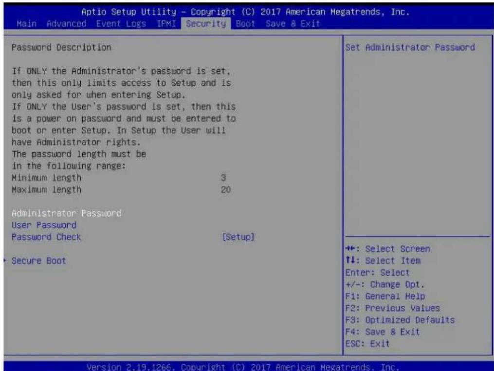
text_image
Aptio Setup Utility - Copyright (C) 2017 American Megatrends, Inc. Main Advanced Event Logs IPMI Security Boot Save & Exit Password Description If ONLY the Administrator's password is set, then this only limits access to Setup and is only asked for when entering Setup. If ONLY the User's password is set, then this is a power on password and must be entered to boot or enter Setup. In Setup the User will have Administrator rights. The password length must be in the following range: Minimum length 3 Maximum length 20 Administrator Password User Password Password Check [Setup] - Secure Boot Set Administrator Password ++: Select Screen ↑↓: Select Item Enter: Select +/-: Change Opt. F1: General Help F2: Previous Values F3: Optimized Defaults F4: Save & Exit ESC: Exit Version 2.19.1266. Copyright (C) 2017 American Megatrends, Inc.Administrator Password
Press Enter to set the user password which is required to enter the BIOS setup utility. The length of the password should be from 3 characters to 20 characters long.
User Password
Press Enter to set the user password which is required to enter the BIOS setup utility. The length of the password should be from 3 characters to 20 characters long.
Password Check
Select Setup for the system to check for a password at Setup. Select Always for the system to check for a password at bootup or upon entering the BIOS Setup utility. The options are Setup and Always.
▶Secure Boot
This section displays the contents of the following secure boot features:
- System Mode
- Secure Boot
- Vendor Keys
Secure Boot
Use this item to enable secure boot. The options are Disabled and Enabled.
Secure Boot Mode
Use this item to select the secure boot mode. The options are Standard and Custom.
CSM Support
Select Enabled to support the EFI Compatibility Support Module (CSM), which provides compatibility support for traditional legacy BIOS for system boot. The options are Disabled and Enabled.
▶Key Management
This submenu allows the user to configure the following Key Management settings.
Provision Factory Defaults
Select Enabled to install the default Secure-Boot keys set by the manufacturer. The options are Disabled and Enabled.
▶Enroll all Factory Default Keys
Select Yes to install all default secure keys set by the manufacturer. The options are Yes and No.
▶Enroll Efi Image
This feature allows the image to run in Secure Boot Mode. Enroll SHA256 Hash Certificate of the image into the Authorized Signature Database.
▶ Save all Secure Boot variables
This feature allows the user to decide if all secure boot variables should be saved.
Secure Boot variable: Size/Key#/Key Source
▶ Platform Key (PK)
This feature allows the user to configure the settings of the platform keys.
Set New
Use this feature to load the new platform keys (PK) from the manufacturer's defaults.
▶Key Exchange Keys (KEK)
Select Set New to load the KEK from the manufacturer's defaults. Select Append to add the KEK from the manufacturer's defaults list to the existing KEK. The default setting is Set New.
▶ Authorized Signatures
Authorized Signature Database (DB) contains authorized signing certificates and digital signatures. Select Set New to load the DB from the manufacturer's defaults. Select Append to add the database from the manufacturer's defaults to the existing DB. The default setting is Set New.
▶Forbidden Signatures
Forbidden Signature Database (DBX) contains forbidden certificates and digital signatures. Select Set New to load the DBX from the manufacturer's defaults. Select Append to add the DBX from the manufacturer's defaults to the existing DBX. The default setting is Set New.
▶ Authorized TimeStamps
Select Set New to load the Authorized Timestamp Database (DBT) from the manufacturer's defaults. Select Append to add the DBT from the manufacturer's defaults list to the existing DBT. The default setting is Set New.
▶OsRecovery Signatures
Select Set New to load the OsRecovery Signatures Database (DBR) from the manufacturer's defaults. Select Append to add the DBR from the manufacturer's defaults list to the existing DBR. The default setting is Set New.
6.7 Boot
Use this tab page to configure Boot Settings.

text_image
Aptio Setup Utility - Copyright (C) 2017 American Megatrends, Inc. Main Advanced Event Logs IPMI Security Boot Save & Exit Boot Configuration Boot mode select [DUAL] LEGACY to EFI support [Disabled] FIXED BOOT ORDER Priorities Boot Option #1 [Hard Disk] Boot Option #2 [CD/DVD] Boot Option #3 [USB Hard Disk] Boot Option #4 [USB CD/DVD] Boot Option #5 [USB Key:Sony Stor...] Boot Option #6 [USB Floppy] Boot Option #7 [USB Lan] Boot Option #8 [Network:IBA XE S1...] Boot Option #9 [UEFI Hard Disk] Boot Option #10 [UEFI CD/DVD] Boot Option #11 [UEFI USB Hard Disk] Boot Option #12 [UEFI USB CD/DVD] Boot Option #13 [UEFI USB Key] Boot Option #14 [UEFI USB Floppy] Boot Option #15 [UEFI USB Lan] Boot Option #16 [UEFI Network] Boot Option #17 [UEFI AP:UEFI: Bui...] ► Delete Boot Option Select boot mode LEGACY/UEFI +: Select Screen ↑↓: Select Item Enter: Select +/-: Change Opt. F1: General Help F2: Previous Values F3: Optimized Defaults F4: Save & Exit ESC: Exit Version 2.19.1266. Copyright (C) 2017 American Megatrends, Inc.Boot mode select
Use this item to select the type of device that the system is going to boot from. The options are LEGACY, UEFI, and DUAL. The default setting is DUAL.
LEGACY to EFI support
Use this item to enable the EFI boot support. The options are Disabled and Enabled.
FIXED BOOT ORDER Priorities
This option prioritizes the order of bootable devices that the system to boot from. Press
*If the item above set to Legacy/UEFI/Dual, the following items will be displayed:
• Legacy/UEFI/Dual Boot Order #1
• Legacy/UEFI/Dual Boot Order #2
• Legacy/UEFI/Dual Boot Order #3
• Legacy/UEFI/Dual Boot Order #4
• Legacy/UEFI/Dual Boot Order #5
• Legacy/UEFI/Dual Boot Order #6
• Legacy/UEFI/Dual Boot Order #7
• Legacy/UEFI/Dual Boot Order #8
• UEFI/Dual Boot Order #9
- Dual Boot Order #10
• Dual Boot Order #11
• Dual Boot Order #12
• Dual Boot Order #13
• Dual Boot Order #14
• Dual Boot Order #15
• Dual Boot Order #16
• Dual Boot Order #17
▶ Delete Boot Option
Use this feature to remove a pre-defined boot device from which the system will boot during startup. The options are Select one to Delete and UEFI: Built-in EFI Shell.
▶UEFI Application Boot Priorities
This feature allows the user to specify which UEFI devices are boot devices.
Boot Option #1
The options are UEFI: Built-in EFI Shell and Disabled.
▶Network Drive BBS Priorities
This feature allows the user to specify which available network drives are boot devices.
Boot Option #1
The options are IBA XE Slot 1800 v2358 and Disabled.
6.8 Save & Exit
Use this tab page to configure Save & Exit settings.
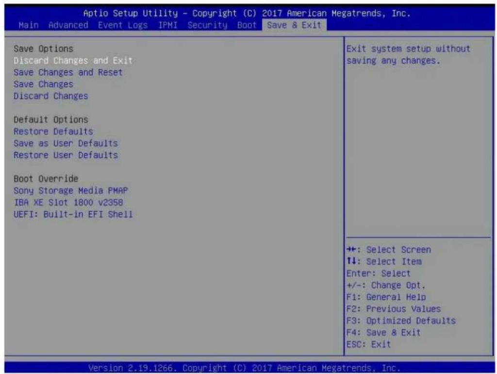
text_image
Aptio Setup Utility - Copyright (C) 2017 American Megatrends, Inc. Main Advanced Event Logs IPMI Security Boot Save & Exit Save Options Discard Changes and Exit Save Changes and Reset Save Changes Discard Changes Default Options Restore Defaults Save as User Defaults Restore User Defaults Boot Override Sony Storage Media PMAP IBA XE Slot 1800 v2358 UEFI: Built-in EFI Shell Exit system setup without saving any changes. +: Select Screen ↑↓: Select Item Enter: Select +/-: Change Opt. F1: General Help F2: Previous Values F3: Optimized Defaults F4: Save & Exit ESC: Exit Version 2.19.1266. Copyright (C) 2017 American Megatrends, Inc.Save Options
Discard Changes and Exit
Select this option to quit the BIOS Setup without making any permanent changes to the system configuration, and reboot the computer. Select Discard Changes and Exit from the Exit menu and press
Save Changes and Reset
After completing the system configuration changes, select this option to save the changes you have made. This will reset (reboot) the system.
Save Changes
When you have completed the system configuration changes, select this option to save all changes made. This will not reset (reboot) the system.
Discard Changes
Select this option and press
Listed on this section are other boot options for the system (i.e., Built-in EFI shell). Select an option and press
Default Options
Restore Defaults
To set this feature, select Restore Optimized Defaults from the Save & Exit menu and press
Save As User Defaults
To set this feature, select Save as User Defaults from the Exit menu and press
To set this feature, select Restore User Defaults from the Exit menu and press
Boot Override
Listed on this section are other boot options for the system (i.e., Built-in EFI shell). Select an option and press
Appendix A
BIOS Error Codes
A.1 BIOS Error Beep (POST) Codes
During the POST (Power-On Self-Test) routines, which are performed each time the system is powered on, errors may occur.
Non-fatal errors are those which, in most cases, allow the system to continue the boot-up process. The error messages normally appear on the screen.
Fatal errors are those which will not allow the system to continue the boot-up procedure. If a fatal error occurs, you should consult with your system manufacturer for possible repairs.
These fatal errors are usually communicated through a series of audible beeps. The table below lists some common errors and their corresponding beep codes encountered by users.
| BIOS Error Beep (POST) Codes | ||
| Beep Code Error | Message Description | |
| 1 short Refresh Circuits have been reset (Ready to power up) | ||
| 5 short, 1 long Memory error No memory detected in system | ||
| 5 long, 2 short Display memory read/write error Video adapter missing or with faulty memory | ||
| 1 long continuous System OH System overheat condition | ||
A.2 Additional BIOS POST Codes
The AMI BIOS supplies additional checkpoint codes, which are documented online at http://www.supermicro.com/support/manuals/ ("AMI BIOS POST Codes User's Guide").
When BIOS performs the Power On Self Test, it writes checkpoint codes to I/O port 0080h. If the computer cannot complete the boot process, a diagnostic card can be attached to the computer to read I/O port 0080h (Supermicro p/n AOC-LPC80-20).
For information on AMI updates, please refer to http://www.ami.com/products/.
Appendix B
Standardized Warning Statements for AC Systems
About Standardized Warning Statements
The following statements are industry standard warnings, provided to warn the user of situations which have the potential for bodily injury. Should you have questions or experience difficulty, contact Supermicro's Technical Support department for assistance. Only certified technicians should attempt to install or configure components.
Read this appendix in its entirety before installing or configuring components in the Supermicro chassis.
These warnings may also be found on our website at http://www.supermicro.com/about/policies/safety_information.cfm.
Warning Definition

Warning! This warning symbol means danger. You are in a situation that could cause bodily injury. Before you work on any equipment, be aware of the hazards involved with electrical circuitry and be familiar with standard practices for preventing accidents.
警告の定義
この警告サインは危険を意味します。
Installation Instructions

Warning! Read the installation instructions before connecting the system to the power source.
設置手順書
Warning! This product relies on the building's installation for short-circuit (overcurrent) protection. Ensure that the protective device is rated not greater than: 250 V, 20 A.
サーキット・ブレーカー
Power Disconnection Warning

Warning! The system must be disconnected from all sources of power and the power cord removed from the power supply module(s) before accessing the chassis interior to install or remove system components.
電源切断の警告
Equipment Installation

Warning! Only trained and qualified personnel should be allowed to install, replace, or service this equipment.
機器の設置
Warning! This unit is intended for installation in restricted access areas. A restricted access area can be accessed only through the use of a special tool, lock and key, or other means of security. (This warning does not apply to workstations).
アクセス制限区域
Warning! There is the danger of explosion if the battery is replaced incorrectly. Replace the battery only with the same or equivalent type recommended by the manufacturer. Dispose of used batteries according to the manufacturer's instructions
電池の取り扱い
Redundant Power Supplies

Warning! This unit might have more than one power supply connection. All connections must be removed to de-energize the unit.
冗長電源装置
Warning! Hazardous voltage or energy is present on the backplane when the system is operating. Use caution when servicing.
バックプレーンの電圧
Comply with Local and National Electrical Codes

Warning! Installation of the equipment must comply with local and national electrical codes.
地方および国の電気規格に準拠
Warning! Ultimate disposal of this product should be handled according to all national laws and regulations.
製品の廃棄
Warning! Hazardous moving parts. Keep away from moving fan blades. The fans might still be turning when you remove the fan assembly from the chassis. Keep fingers, screwdrivers, and other objects away from the openings in the fan assembly's housing.
ファン・ホットスワップの警告
Power Cable and AC Adapter

Warning! When installing the product, use the provided or designated connection cables, power cables and AC adaptors. Using any other cables and adaptors could cause a malfunction or a fire. Electrical Appliance and Material Safety Law prohibits the use of UL or CSA-certified cables (that have UL/CSA shown on the cord) for any other electrical devices than products designated by Supermicro only.
電源コードとACアダプター
System Specifications
Processors
Dual Intel Xeon 82xx/62xx/52xx/42xx/32xx or 81xx/61xx/51xx/41xx/31xx processors in a P (LGA3647) type socket Note: Please refer to the motherboard specifications pages on our website for updates to supported processors.
Chipset
Intel C621 chipset
BIOS
AMI 32Mb SPI Flash ROM
Memory
Twenty-four slots for up to 6 TB of 3DS Load Reduced DIMM (3DS LRDIMM), 3DS Registered DIMM (3DS RDIMM), or up to 3 TB of Load Reduced DIMM (LRDIMM) with speeds of up to 2933 MHz; support for Non-Volatile DIMM (NVDIMM) and Intel Optane DC Persistent Memory (DCPMM); DIMM size up to 256 GB at 1.2 V
Drive Bays
Twenty-four hot-swap 2.5" bays for fourteen SATA3 drives, or an option for twenty SAS3 plus four NVMe/SAS3 (Optional) Two rear hot-swap 2.5" SATA (Optional) M.2: 1 M.2 NVMe (2242/2260/2280*/22110*); 1 M.2 SATA (2242/2260/2280*/22110*) via optional SATA cable
PCI Expansion Slots
Two full-height, double-width, PCIe slots (one x8, one x16), four full-height, full-width x8 PCIe slots, one low-profile x8 PCIe slot, one internal low-profile PCIe x8 slot (Ultra riser) Note: Model E1CR4T is different--see pg 53.
Motherboard
X11DPU; Length 17.0", width 16.8" (431.8 mm x 426.7 mm)
Chassis
SC219U2AC4-R1K02-T; 2U Rackmount, (WxHxD) 17.2 x 3.5 x 27.8 in. (437 x 89 x 706 mm)
System Cooling
Four 80x80x38 mm, 9.5K RPM fans, two CPU heatsinks, two air shrouds to direct air flow
Weight
Net Weight: 39 lbs (17.7 kg) Gross Weight: 63 lbs (28.6 kg)
Power Supply
Model: PWS-1K02A-1R, 800/1000 W redundant modules, 80Plus Titanium level Input: 100-127Vac / 9.8–7 A / 50-60 Hz 200-240Vac / 7–5 A / 50-60 Hz +12V: Max: 66.7 A / Min: 0 A (100-127 Vac) Max: 83 A / Min: 0 A (200-240 Vac) +12 V standby: Max: 2.1 A / Min: 0 A
Operating Environment
Operating Temperature: 10^ to 35^ ( 50^ to 95^ )
Non-operating Temperature: -40^ to 70^ ( -40^ to 158^ )
Operating Relative Humidity: 8% to 90% (non-condensing)
Non-operating Relative Humidity: 5% to 95% (non-condensing)
Regulatory Compliance
Electromagnetic Emissions: FCC Class A, EN 55032 Class A, EN 61000-3-2/3-3, CISPR 32 Class A
Electromagnetic Immunity: EN 55024/CISPR 24, (EN 61000-4-2, EN 61000-4-3, EN 61000-4-4, EN 61000-4-5, EN 61000-4-6, EN 61000-4-8, EN 61000-4-11)
Other: VCCI-CISPR 32 and AS/NZS CISPR 32
Environmental: Directive 2011/65/EU and Delegated Directive (EU) 2015/863 and Directive 2012/19/EU
Safety: CSA/EN/IEC/UL 60950-1 Compliant, UL or CSA Listed (USA and Canada), CE Marking (Europe)
Perchlorate Warning
California Best Management Practices Regulations for Perchlorate Materials: This Perchlorate warning applies only to products containing CR (Manganese Dioxide) Lithium coin cells. "Perchlorate Material-special handling may apply. See www.dtsc.ca.gov/hazardouswaste/perchlorate"
Appendix D
UEFI BIOS Recovery
Warning: Do not upgrade the BIOS unless your system has a BIOS-related issue. Flashing the wrong BIOS can cause irreparable damage to the system. In no event shall Supermicro be liable for direct, indirect, special, incidental, or consequential damages arising from a BIOS update. If you do update the BIOS, do not shut down or reset the system while the BIOS is updating to avoid possible boot failure.
D.1 Overview
The Unified Extensible Firmware Interface (UEFI) provides a software-based interface between the operating system and the platform firmware in the pre-boot environment. The UEFI specification supports an architecture-independent mechanism that will allow the UEFI OS loader stored in an add-on card to boot the system. The UEFI offers clean, hands-off management to a computer during system boot.
D.2 Recovering the UEFI BIOS Image
A UEFI BIOS flash chip consists of a recovery BIOS block and a main BIOS block (a main BIOS image). The recovery block contains critical BIOS codes, including memory detection and recovery codes for the user to flash a healthy BIOS image if the original main BIOS image is corrupted. When the system power is turned on, the recovery block codes execute first. Once this process is complete, the main BIOS code will continue with system initialization and the remaining POST (Power-On Self-Test) routines.
Note 1: Follow the BIOS recovery instructions below for BIOS recovery when the main BIOS block crashes.
Note 2: When the BIOS recovery block crashes, you will need to follow the procedures to make a Returned Merchandise Authorization (RMA) request. Also, you may use the Supermicro Update Manager (SUM) Out-of-Band (https://www.supermicro.com.tw/products/nfo/SMS_SUM.cfm) to reflash the BIOS.
D.3 Recovering the Main BIOS Block with a USB Device
This feature allows the user to recover the main BIOS image using a USB-attached device without additional utilities used. A USB flash device such as a USB Flash Drive, or a USB CD/DVD ROM/RW device can be used for this purpose. However, a USB Hard Disk drive cannot be used for BIOS recovery at this time.
The file system supported by the recovery block is FAT (including FAT12, FAT16, and FAT32) which is installed on a bootable or non-bootable USB-attached device. However, the BIOS might need several minutes to locate the SUPER.ROM file if the media size becomes too large due to the huge volumes of folders and files stored in the device.
To perform UEFI BIOS recovery using a USB-attached device, follow the instructions below.
- Using a different machine, copy the "Super.ROM" binary image file into the Root "\" directory of a USB device or a writable CD/DVD.
Note 1: If you cannot locate the "Super.ROM" file in your drive disk, visit our website at www.supermicro.com to download the BIOS package. Extract the BIOS binary image into a USB flash device and rename it "Super.ROM" for the BIOS recovery use.
Note 2: Before recovering the main BIOS image, confirm that the "Super.ROM" binary image file you download is the same version or a close version meant for your motherboard.
- Insert the USB device that contains the new BIOS image ("Super.ROM") into your USB drive and reset the system when the following screen appears.
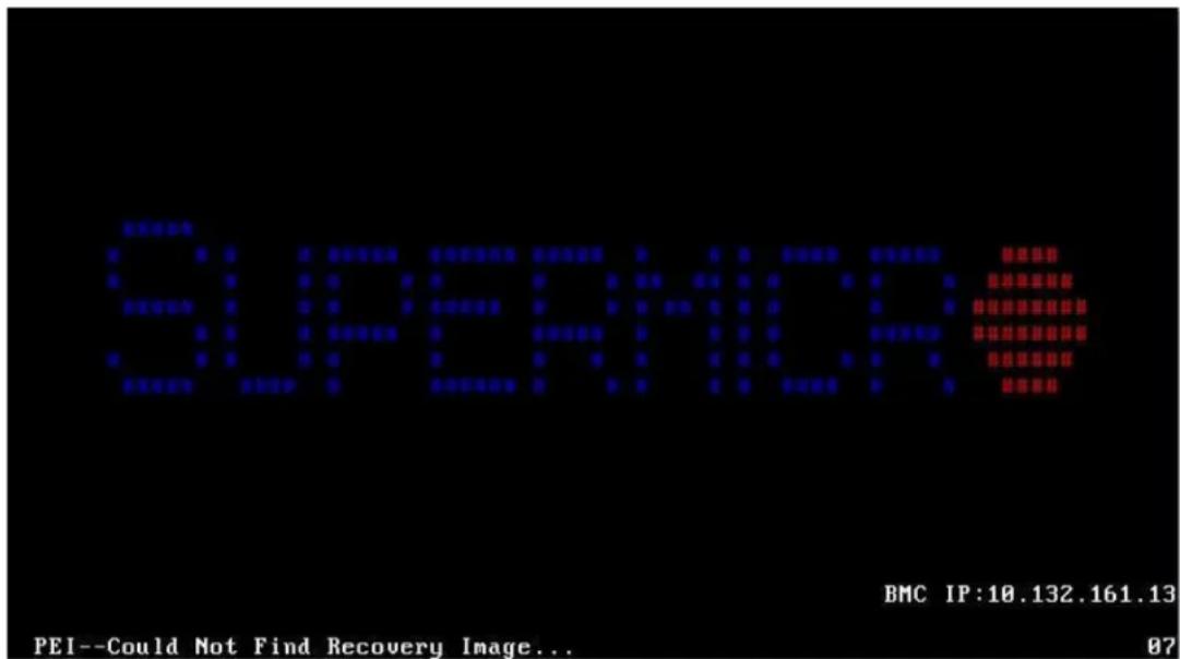
text_image
SUPERIOR BMC IP:10.132.161.13 PEI--Could Not Find Recovery Image... 87- After locating the healthy BIOS binary image, the system will enter the BIOS Recovery menu as shown below.
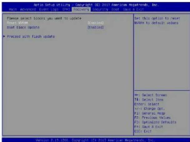
text_image
Optin Setup Utility - Copyright (C) 2017 American Megatrends, Inc. Main Advanced Event Log (PWI Recovery Security Boot Save a Exit Please select blocks you want to update Reset View [Enabled] Boot Block Update [Enabled] ► Proceed with flash update Set this option to reset MVRW to default values +1: Select Screen T4: Select Item Enter: Select +/-: Change Out. F1: General Help F2: Previous Values F3: Optimized Defaults F4: Save & Exit ESC: Exit Version 2.19.1706 Copyright (C) 2017 American Megatrends, Inc.Note: At this point, you may decide if you want to start the BIOS recovery. If you decide to proceed with BIOS recovery, follow the procedures below.
- When the screen as shown above displays, use the arrow keys to select the item "Proceed with flash update" and press the
key. You will see the BIOS recovery progress as shown in the screen below.
Note: Do not interrupt the BIOS flashing process until it has completed.
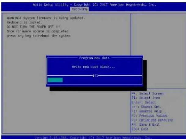
text_image
Aotis Setup Utility - Copyright (C) 2017 American Megatrends, Inc. Anotis WARNING! System firmware is being updated. Keyboard is locked. DO NOT TURN THE POWER OFF!!! Slice firmware update is completed press any key to reboot the system Program new data Write new boot block... 178 +: Select Screen T4: Select item Enter: Select +/-: Change Opt. F1: General Help F2: Previous Values F3: Optimized Defaults F4: Save & Exit ECC: Exit Version 2.19.1266. Copyright (C) 2017 American Megatrends, Inc.- After the BIOS recovery process is complete, press any key to reboot the system.
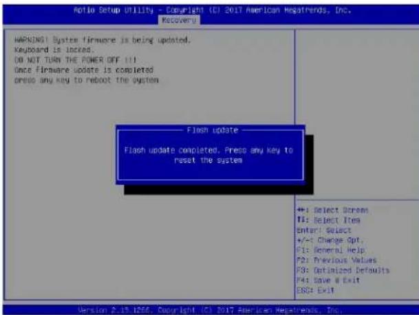
text_image
Aptio Setup Utility - Copyright (C) 2017 American Hegafriends, Inc. Recovery WARNING System firmware is being updated. Keyboard is locked... DO NOT TURN THE POWER OFF !!! Once firmware update is completed press any key to reboot the system Flash update Flash update completed. Press any key to reset the system +: Select Screen T1: Select Item Enter: Select +/-t Change Opt. F1: General Help F2: Previous Values F3: Optimized Defaults F4: Save @ Exit ESC: Exit Version 2.19.1256, Copyright (C) 2017 American Hegafriends, Inc.- Using a different system, extract the BIOS package into a USB flash drive.
- Press
continuously during system boot to enter the BIOS Setup utility. From the top of the tool bar, select Boot to enter the submenu. From the submenu list, select Boot Option #1 as shown below. Then, set Boot Option #1 to [UEFI AP:UEFI: Built-in EFI Shell]. Pressto save the settings and exit the BIOS Setup utility.

text_image
Boot Configuration Boot mode select LEGNOV to EFI support FD803 BOOT ONION Priorities Boot Option #1 Boot Option #2 Boot Option #3 Boot Option #4 Boot Option #5 Boot Option #6 Boot Option #7 Boot Option #8 Boot Option #9 Boot Option #10 Boot Option #11 Boot Option #12 Boot Option #13 Boot Option #14 Boot Option #15 Boot Option #16 Boot Option #17 Add New Boot Option [DUAL] [Disabled] [DEF1 UP/UEFI: Null...] [COV/DVD] [USB Hard Disk] [USB Co/DVI] [USB Key/SanDisk] [USB Floppy] [USB Lan] [Network: IBM OE 91...] [UEFI Hard Disk] [UEFI USB/DVD] [UEFI USB Hard Disk] [UEFI USB CO/DVI] [UEFI USB Key/UEFI...] [UEFI USB Floppy] [UEFI USB Lan] [UEFI Network] [Hard Disk] Sets the system boot order +: Select Screen T4: Select Item Enters: Select +/-: Change Opt. (F1 General) help Fst Previous Values #3: Optimized Defaults F4: Save & Exit ESC: Exit Version 8.19.1266. Copyright (C) 2017 American Megatrends, Inc.- When the UEFI Shell prompt appears, type fs# to change the device directory path. Go to the directory that contains the BIOS package you extracted earlier from Step 6. Enter flash.nsh BIOSname.### at the prompt to start the BIOS update process.
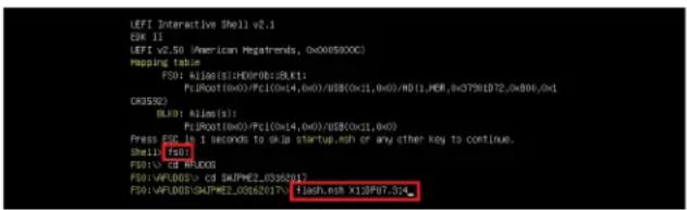
text_image
LEFI Interactive Shell v2.1 ESK 11 LEFI v2.50 (American Regatrends, 0x00890XX) Mapping table: F30: A106(0x1):H0D(P01:BKL1): PcJR001(0x0)/PcI(0x14,0x0)/uB(0x11,0x0)/M01_MER,0xG7901D2,0x806,0x1 OR3532) BLXD: BLXD(s): PcJR001(0x0)/PcI(0x14,0x0)/uB(0x11,0x0) Press ESCB is 1 seconds to disk startup.msh or any other key to continue. Shell (f5) F30: CD BRUDOS F30:VAPL005> CD SKAPME2_03562017 F30:VAPL005@SKAPME2_03562017\ flash.nsh X13P07.SXNote: Do not interrupt this process until the BIOS flashing is complete.
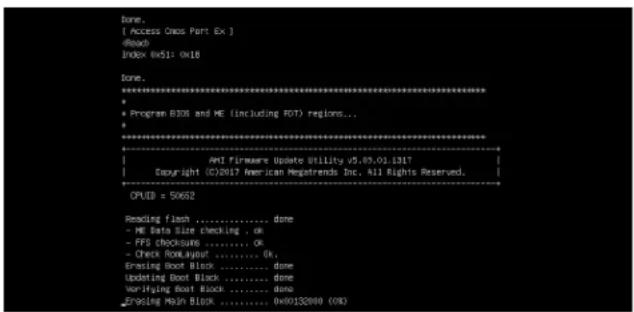
text_image
Done. [ Access Oxxx Part Ex ] Reads Index 0x51: 0x18 Done. ********************************************************************** * Program BIOS and ME (including RDT) regions... ****************************************************************... AMT Firmware Update Utility v5.49.01.1317 Copyright ©2017 American Registrends Inc. All Rights Reserved. OPUD = 50652 Reading Flash ....... done - ME Data Size checking . ok - PFS checksums ....... ok - Check BookLayout ....... ok Erasing Boot Block ....... done Updating Boot Block ....... done Verifying Boot Block ....... done Zranging Mesh Block ....... 0x00152000 (OK)- The screen above indicates that the BIOS update process is complete. When you see the screen above, unplug the AC power cable from the power supply, clear CMOS, and plug the AC power cable in the power supply again to power on the system.

text_image
Verifying HCB Block ....... done - Update success for FEM - Update success for SE. - Successful Update Recovery Loader to (PRx!! - Successful Update MFSB11- - Successful Update FTRM11- - Successful Update NFs, [081 and 19021] - Successful Update FLOD and UTOK11 - ML entire image update success 11 WAVRNDG : System must power-sif to have the changes take effect! Moving FS01\AFUDOS\SKJPME2_03162027\fdxt64.efi -> FS01\AFUDOS\SKJPME2_03162017\f df.sac - [c4] Moving FS01\AFUDOS\SKJPME2_03162027\fauffix64.efi -> FS01\AFUDOS\SKJPME2_0316201 ?fauffix_sac - [c4] ****************************************************************************************** * * Please ignore this 'shell cannot read from file - device error' * Warning message due to it does not impact flashing process. * ****************************************************************************************** baating ' ' Delete successful. FSb-> _- Press
continuously to enter the BIOS Setup utility. - Press
to load the default settings. - After loading the default settings, press
to save the settings and exit the BIOS Setup utility.
Appendix E
IPMI Crash Dump
In the event of a processor internal error (IERR) that crashes your system, you may want to provide information to support staff. You can download a crash dump of status information using IPMI. The IPMI manual is available at https://www.supermicro.com/solutions/IPMI.cfm.
Check IPMI Error Log
- Access the IPMI web interface.
- Click the Server Health tab, then Event Log to verify an IERR error.

text_image
Host Identification Server: 172 031 040 125 User: ADMIN (Administrator) System Server Health Configuration Remote Control Virtual Media Maintenance Miscellaneous Help Server Health Sensor Readings Event Log Event Log For more special event log settings, please click here This page displays events from the system's event log. You can choose a category from the pull-down box to filter the events and also sort them by clicking on a column header Clear Event Log Save Select an event log category: All Events Event ID Time Stamp Sensor Name Sensor Type Description 1 2017/10/19 15:38:37 Processor IERR - Assertion 2 2017/10/19 15:50:20 Processor IERR - AssertionFigure E-1. IPMI Event Log
In the event of an IERR, the BMC executes a crash dump. You must download the crash dump and save it.
Downloading the Crash Dump File
- In the IPMI interface, click the Miscellaneous tab, then the Trouble Shooting option.
- Click the Dump button and wait five minutes for the file to be created. (No confirmation message will appear.)
- Click the Download button and a Save As dialog appears.
- Save the zipped dump file, noting the name and location.
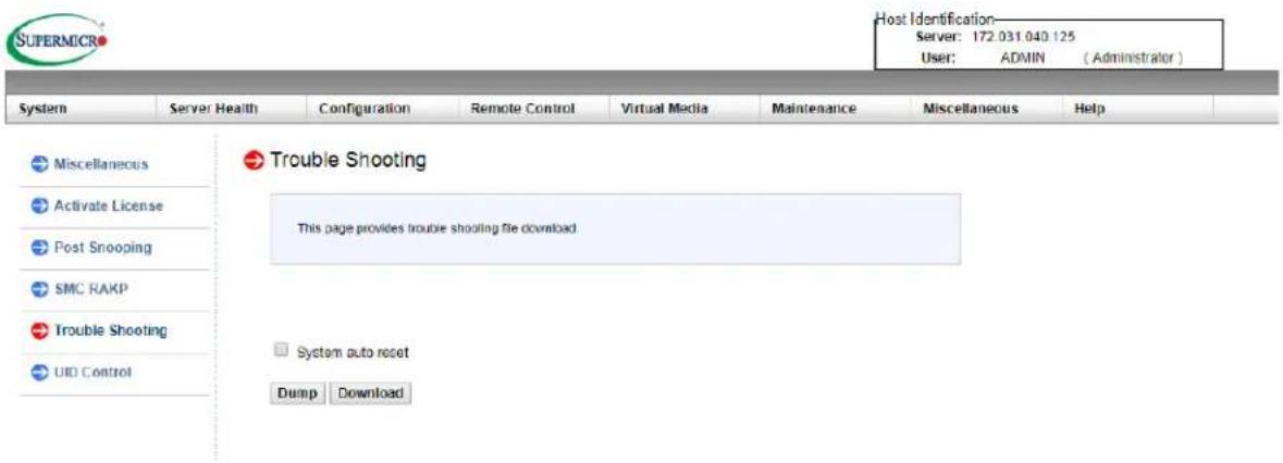
text_image
Host Identification Server: 172.031.040.125 User: ADMIN (Administrator) System Server Health Configuration Remote Control Virtual Media Maintenance Miscellaneous Help Miscellaneous Activate License Post Snooping SMC RAKP Trouble Shooting UID Control Trouble Shooting This page provides trouble shooting file download System auto reset Dump DownloadFigure E-2. IPMI Crash Dump Download
Note: The System auto reset check box dictates behavior after an IERR. If checked, the system will restart automatically, and the dump file will be erased. If not, the system remains in a failed state. Do not check this box until after the dump file has been sent to Support.
Appendix F
GPUs in 2U Ultra Systems
Supermicro 2U Ultra systems support graphic processing units (GPUs) when installed with some additional optional parts. The GPUs have cooling requirements that can be assisted by specialized dual-level air shrouds to direct the flow from the system fans.

text_image
Diagram of a server rack with labeled components including ports, connectors, and memory drivesFigure F-1. Expansion Card Chassis Slots
In the diagram above, slots 1, 2, 5/6, and 7/8 can be used for GPUs. Note that due to thermal limitations, a maximum of two GPUs should normally be installed. Positions 1 and 2 cannot be installed in the same system; the air shrouds are mutually exclusive. Position 7/8 should only be used after consultation with Supermicro.
| Default Expansion Card Configurations | |||
| Slot | Mechanical Electrical In Models | ||
| 1 Double-width, full-height, full-length x16 (CPU1) All models | |||
| 2 Double-width, full-height, full-length | x16 (CPU1)x8 (CPU1) | Depends on model | |
| 5/6 Full-height, full-length x8 (CPU2) All models | |||
| 7/8* Full-height, full-length x8 (CPU2) All models | |||
*Only supported in special circumstances, in consultation with Supermicro
Optional Riser Cards
• AOC-2UR66-i4G: Slot 1 x16 (CPU1), Slot 2 x16 (CPU1), Slot 3 N/A
• RSC-R2UW-2E8E16: Slot 5 x16 (CPU2), Slot 7 x8 (CPU2), Slot 8 x8 (CPU2)
• RSC-W2-66: Slot 5 x16 (CPU2), Slot 7 x16 (CPU2)
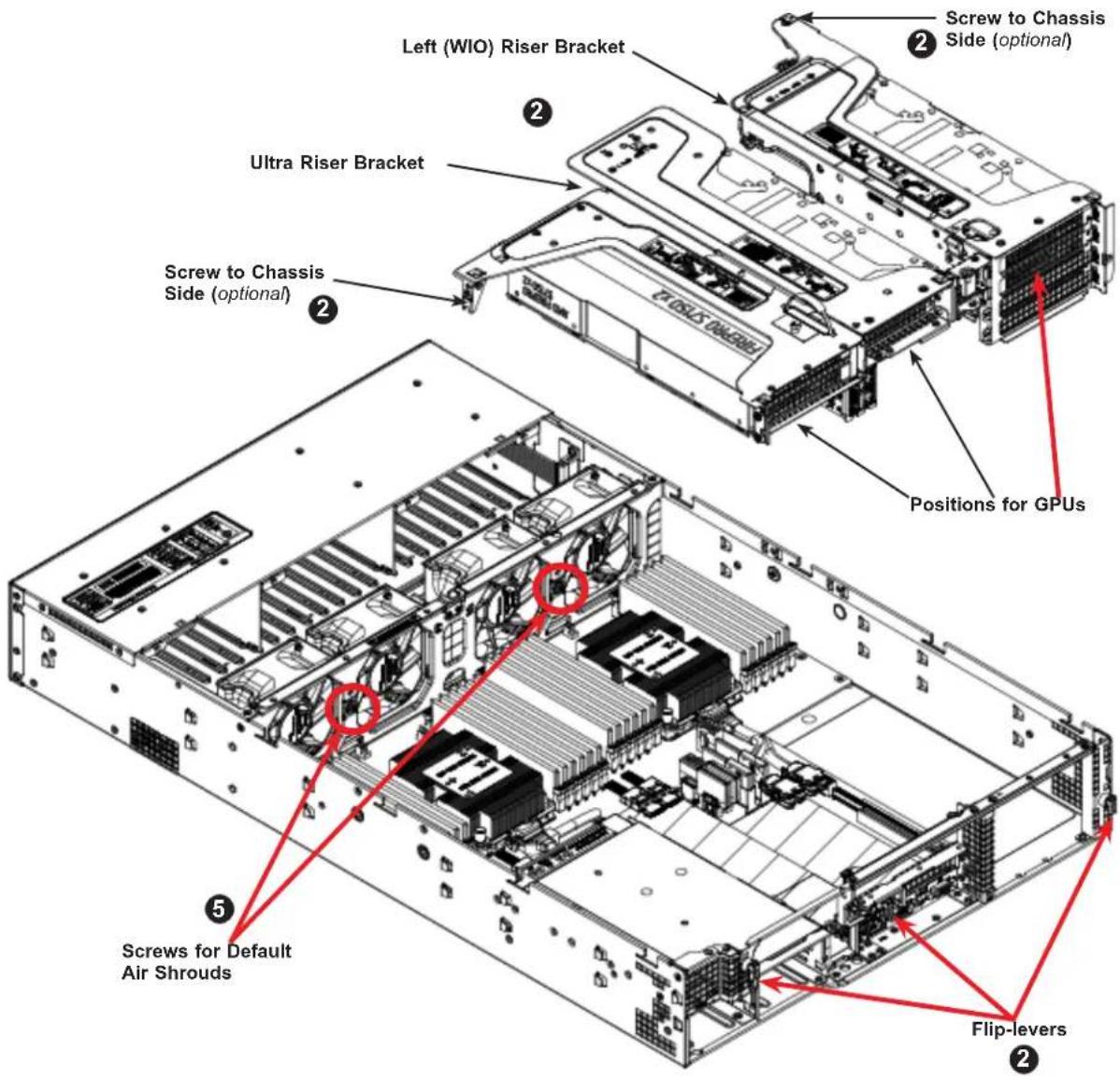
text_image
Screw to Chassis Side (optional) Left (WIO) Riser Bracket Ultra Riser Bracket Screw to Chassis Side (optional) Positions for GPUs Screws for Default Air Shrouds Flip-leversFigure F-2. Riser Cards and GPU Positions
Adding GPUs
- Power down the system, unplug AC cords, and remove the top chassis cover.
- Remove the appropriate riser card bracket, pictured above. On the rear of the chassis, each bracket is secured by a small black plastic flip-lever with an arrow on it. Flip open the appropriate lever to release the bracket, then pull the bracket out of the chassis. For the Ultra riser (center) bracket, there is a thumbscrew to a standoff in the chassis center.
- Insert the GPU into the riser card slot while aligning the GPU rear L-shaped mounting bracket. Add screws to secure the GPU L-shaped mounting bracket.

text_image
GPU Rear L Bracket for Left-side GPUFigure F-3. Inserting the Left-side GPUs into the Riser Card Bracket

text_image
GPU Rear L Bracket for Middle GPU Screw to Standoff on Chassis Floor Rear L Bracket for Right-side GPU GPUFigure F-4. Inserting the Middle and Right-side GPUs into the Riser Card Bracket
- Secure the front end of the GPU to the bracket with screws. For one left-side GPU, a middle GPU, or a right-side GPU the front bracket is pre-installed on the riser card bracket.
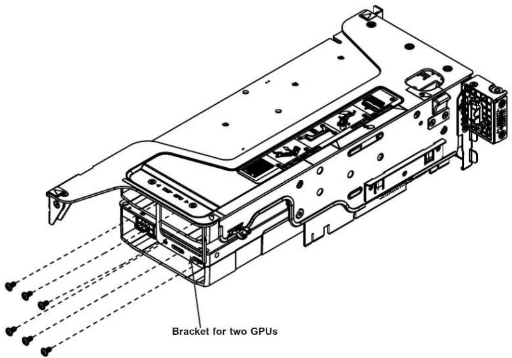
text_image
Bracket for two GPUsFigure F-5. Attaching the Front Bracket for the Left-side GPUs
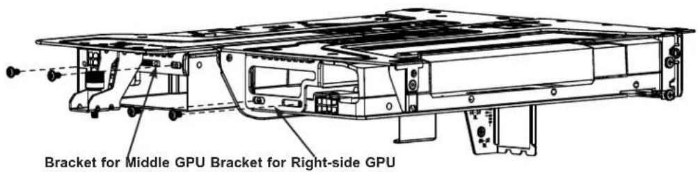
text_image
Bracket for Middle GPU Bracket for Right-side GPUFigure F-6. Attaching the Front Bracket for Middle and Right-side GPUs
- Remove the two screws on the fan housing that secure the default air shrouds. (See Figure F-2)
- Place the appropriate air shroud (see the following notes). Insert the shroud tabs into the slot at the top of the fan housing.
- Place the riser card bracket with GPU into the chassis. First, insert the cables and front end of the GPU into the throat of the air shroud. Then align and insert the riser card into the motherboard slot while aligning the bracket into the chassis.
- Secure the bracket into the chassis. At the chassis rear, flip the small black plastic flip-lever to secure it. For the Ultra riser (center) bracket, use the thumbscrew to secure the bracket to the standoff in the chassis center. For either bracket, an optional screw can secure it to the chassis side.
- Route the GPU power cable and plug it into the motherboard.
- Close and power up the system.
Notes for Installing in the Upper Left-side Position (5/6)
- Break off the necessary portions of the shroud to allow for cables. In particular, remove some tabs on the top, as indicated.
- Position the shroud as shown in Figure F-3. The right wall of the shroud just covers CPU2.
- Routing the GPU power cables: Guide the cables up between the GPU and the shroud, then over the top of the shroud and down to the GPU_PWR3 or GPU_PWR4 connector on the motherboard. Make cables flat as possible. It is normal for the shroud to bend slightly under the cables.
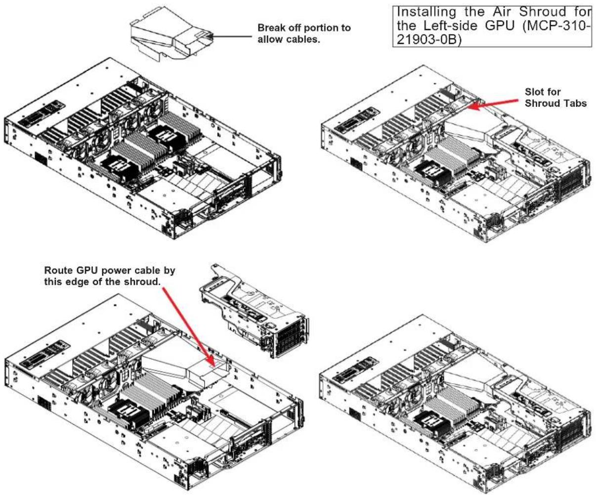
text_image
Break off portion to allow cables. Installing the Air Shroud for the Left-side GPU (MCP-310-21903-0B) Slot for Shroud Tabs Route GPU power cable by this edge of the shroud.Figure F-7. Installing a GPU on the Upper Left-side
Notes for Installing in the Lower Left-side Position (7/8)
Installation of a GPU in the 7/8 position is not supported without consultation with Supermicro due to thermal limitations. If the 7/8 position is used, mounting requires MCP-120-82904-0N bracket from accessory box.
Notes for Installing in the Middle Position (2)
- Break off the necessary portions of the shroud to allow for cables. In particular, remove the top row of the shroud "ramp" as labeled below.
- Position the shroud as shown. The right side wall of the shroud should not cover the right-most DIMM (P1-DIMMC1). The hole near the center of the shroud fits over the standoff in the center of the chassis. The left wall of the shroud fits next to CPU2.
- Routing the GPU power cables: You will likely have to route the cables to the motherboard connector before fully seating the riser bracket. Guide the cables to the right between the GPU and the shroud and down to the GPU_PWR1 connector on the motherboard.

text_image
Installing the Air Shroud for the Middle GPU (MCP-310-21904-0B) Break off tabs if necessary. Break off top row of shroud "ramp." Slot for Shroud Tabs Route GPU power cable by this edge of the shroud.Figure F-8. Installing a GPU in the Middle of the Chassis
Notes for Installing in the Right-side Position (1)
- Break off the necessary portions of the shroud to allow for cables.
- Position the shroud as shown. The right side wall of the shroud should not cover the right-most DIMM (P1-DIMMC1). The hole near the center of the shroud fits over the standoff in the center of the chassis. The left wall of the shroud fits next to CPU2.
- Routing the GPU power cables: Connect the cable to GPU_PWR1 on the motherboard before placing the riser bracket and GPU into the chassis. Guide the cables to the left between the GPU and the shroud.
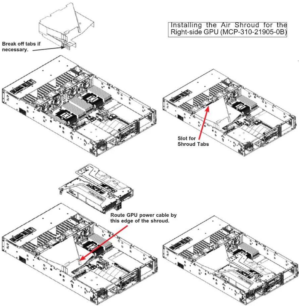
text_image
Break off tabs if necessary. Installing the Air Shroud for the Right-side GPU (MCP-310-21905-0B) Slot for Shroud Tabs Route GPU power cable by this edge of the shroud.Figure F-9. Installing a GPU on the Right-side
Appendix G
CPU-Based RAID for NVMe
Intel® Virtual RAID on CPU (Intel VROC) is an enterprise RAID solution for NVMe SSDs directly attached to Intel Xeon Scalable processors. Intel Volume Management Device (VMD) is an integrated controller inside the CPU PCI-E root complex.
- A single processor supports up to 12 NVMe SSDs and up to 6 RAID arrays.
- A dual processor system supports up to 24 NVMe SSDs and 12 RAID arrays.
Strip sizes are 4K, 8K, 16K, 32K, 64K, 128K.
Requirements and Restrictions
- Intel VROC is only available when the system is configured for UEFI boot mode.
- To enable the mdadm command and support for RSTe, install the patch from
- Linux: https://downloadcenter.intel.com/download/28158/Intel-Virtual-RAID-on-CPU-Intel-VROC-and-Intel-Rapid-Storage-Technology-enterprise-Intel-RSTe-Driver-for-Linux-
- Windows: https://downloadcenter.intel.com/download/28108/Intel-Virtual-RAID-on-CPU-Intel-VROC-and-Intel-Rapid-Storage-Technology-enterprise-Intel-RSTe-Driver-for-Windows-
- To enable Intel VROC, a hardware key must be inserted on the motherboard, and the appropriate processor's Virtual Management Devices must be enabled in the BIOS setup.
- It is possible to enable Intel VROC without a hardware key installed, but only RAID0 will be enabled.
- Intel VROC is not compatible with secure boot. This feature must be disabled.
- When creating bootable OS RAID1 devices, you must have both devices on the same CPU, and a VMD on that CPU.
- Spanning drives when creating RAID devices is not recommended to due to performance issues, even though it is supported.
Supported SSDs and Operating Systems
To see the latest support information: https://www.intel.com/content/www/us/en/support/articles/000030310/memory-and-storage/ssd-software.html
Additional Information
Additional information is available on the product page for the Supermicro add-on card and the linked manuals.
www.supermicro.com/products/accessories/addon/AOC-VROCxxxMOD.cfm
G.1 Hardware Key
The Intel VROC hardware key is a license key that detects the Intel VROC SKU and activates the function accordingly. The key must be plugged into the Supermicro motherboard (connector JRK1). The key options are:
| Intel® VROC Keys | |||
| VROC Package Description Part Number Intel MM Number | |||
| Standard | RAID 0, 1, 10Supports 3rd party SSDs | AOC-VROCSTNMOD 95 | 1605 |
| Premium | RAID 0, 1, 5, 10Supports 3rd party SSDs | AOC-VROCPREMOD 95 | 1606 |
| Intel SSD only | RAID 0, 1, 5, 10Supports Intel SSDs only | AOC-VROCINTMOD 95 | 822 |

text_image
VROC_HW_KEY PIN 1 GND KEY1 GND KEY2Figure G-1. Intel® VROC RAID Key and Motherboard Connector JRK1
G.2 Enabling NVMe RAID
RAID for NVMe SSDs must be enabled through the UEFI BIOS.
- Install the patch as described in the Restrictions and Requirements section on a previous page.
- Reboot the server.
- Press [DEL] key to enter BIOS.
- Switch to Advanced > Chipset Configuration > North Bridge > IIO Configuration > Intel® VMD Technology > CPU1 & CPU2.
- Enable the VMD according to the following rules.
- For U.2 NVMe, enable all the sub-items under each PStack, based on the your model server:
| VMD BIOS Setting for Ultra Servers | ||
| Model CPU1 CPU2 | ||
| 1029U-T VMD Config for PStack0 not needed | ||
| 6019U-TN42029U-T2029U-E1C2029UZ-T6029U-T6029U-E1C6029UZ-T | VMD Config for PStack0 VMD Config for PStack0 | |
| 1029U-TN10 | VMD Config for PStack1VMD Config for PStack2 | VMD Config for PStack1VMD Config for PStack2 |
| 2029U-TN24 VMD Config for PStack1 VMD Config for PStack2 | ||
| 1029UZ-TN20 | VMD Config for PStack0VMD Config for PStack1VMD Config for PStack2 | VMD Config for PStack0VMD Config for PStack1VMD Config for PStack2 |
| 2029UZ-TN20 | VMD Config for PStack0VMD Config for PStack1VMD Config for PStack2 | VMD Config for PStack0VMD Config for PStack2 |
| 1029U-E1C6019U-T | U.2 NVMe not supported | |
- For M.2 NVMe or NVMe AIC, enable the VMD according to which AOC card/slot it used. Examples for some U.2 configurations follow.
• For 1029U-TN10RT populated with ten U.2 NVMe drives:

text_image
VMB Config for Pt/ack VBITAB VMD for Volume Management Device (Database) VMD Config for Pt/ack1 VBITAB VMD for Volume Management Device (Database) AOC-VMMC-22XT WMCE1 VMD (Database) AOC-VMMC-22XT WMCE2 VMD (Database) HOT Plug Capable (Database) VMD Config for Pt/ack2 VBITAB VMD for Volume Management Device (Database) AOC-VMMC-22XT WMCE3 VMD (Database) AOC-VMMC-22XT WMCE4 VMD (Database) AOC-VMMC-22XT WMCE5 VMD (Database) AOC-VMMC-22XT WMCE6 VMD (Database) HOT Plug Capable (Database) Double/Disable Intel8 Volume Management Device Technology in this State. CPU1 Configuration M: Select Screen TA: Select Time Orders: Select w/o Change On, F1: General Hold F2: Previous Value F3: Not Closed Defaults F4: Save & Exit DSC: Exit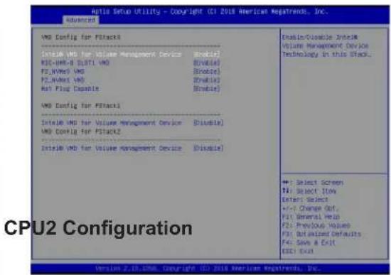
text_image
VMD Config for PStack1 Initial VMD for Value Management Device (Disable) RDC-VMX-D ULST1 VMD F2,NWes1 VMD F2,NWes2 VMD Hot Plug Capsule VMD Config for PStack1 Initial VMD for Value Management Device (Disable) VMD Config for PStack2 Initial VMD for Value Management Device (Disable) Enable/Disable Initial Volume Management Device Technology in this Stack... CPU2 Configuration +1: Select Screen +2: Select Flow Enter: Select +/-5 Change Out. F1: General Web F2: Previous Values F3: Untailized Defaults F4: Save A Exit ESC: Exit• For 2029U-TR or 2029U-E1CR populated with four U.2 NVMe drives:
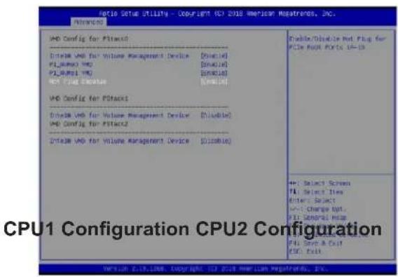
text_image
CPU1 Configuration CPU2 Configuration V4D Config for Pstacks V4D Config for Volume Management Device [Single] P1_Pstack V4D [Single] P1_Pstack V4D [Single] V4D Config for Pstacks V4D Config for Pstacks V4D Config for Volume Management Device [Disable] V4D Config for Pstacks2 V4D Config for Volume Management Device [Disable]
text_image
Auto Setup Utility - Copyright (S) 2018 American Newsrends, Inc. VMD Config for P3ack3 Select VMD for Value Management Device [Enable] RDC-MLA-ERK SLRTI VMD [Disable] PCL-NAo VMD [Enable] PCL-NAo VMD [Enable] NCS-PLC Enable [Disable] VMD Config for P3ack1 Select VMD for Value Management Device [Disable] VMD Config for P3ack2 Select VMD for Value Management Device [Disable] Unable/Disable Not Plot for PC5e Root Parts 14-10 Select Screen T4: Select View Enter Select +/- Draw Out F1: Complete Help F1: From Lost Views F2: Distributed Defaults F4: Save & Exit RSD: EXIT• For 2029U-TN24R4T populated with 24 U.2 NVMe drives:

text_image
Auto Setup Utility - Copyright (C) 2018 American Magistrands, Inc. Advanced VMD Config for PS3600 Intel® VMD for Volume Management Device [Disable] VMD Config for PS3601 Intel® VMD for Volume Management Device [Disable] VMD Config for PS3602 Intel® VMD for Volume Management Device [Enable] ADO=SUMMER+LEAT NAME: VMD [Enable] Hut Plan Console [Enable] Example/Disable Intel® Volume Management Device Technology in this Stock... +:- Select Screen Fkt Select Item Enter: Select +/-: Change Opt. Fkt General Help Fkt Properties Value Fkt Default/Default Defaults Fkt Share & Exit ECD: Exit Version 2.17.1250. Copyright 01 July American Magistrands, Inc.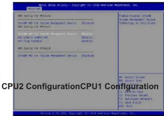
text_image
Auto Setup Utility - Copyright (C) 2008 American Repatriere, Inc. Advanced VMD Config for Stack3 Select VMD for Volume Management Device [Disziable] VMD Config for Stack1 Select VMD for Volume Management Device [Disziable] HDD-DCM4-S NAME: VMD [Disziable] HCP FLOW CREAMLE [Disziable] VMD Config for Stack2 Select VMD for Volume Management Device [Disziable] Enable/Disable SelectVDD McDue Management Device Technology in this Stack. ... Select Screens B: Select Item CPU2 ConfigurationCPU1 Configuration Version 2.19.1268, Copyright 102 New American Repatriere, Inc.Figure G-2. BIOS VMD Setting Examples for Ultra Servers
- Press [F4] to save the configuration and reboot the system.
- Press [DEL] to enter BIOS.
- Switch to Advanced > Intel(R) Virtual RAID on CPU > All Intel VMD Controllers > Create RAID Volume.
- Set Name.
- Set RAID Level.
- If cross-controller RAID is required, select Enable RAID spanned over VMD Controller as shown in Figure G-4.
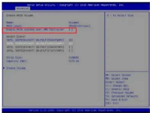
text_image
Auto Setup Utility - Copyright (I) 2018 American Mapsrends, Inc. Created: A35D Volume Name: A35D Level Create A35D Volume over VMD Controller Select Offset DETAIL SUPPECKXHATY SOUTHEPTZASAKAPWNT DETAIL SUPPECKXHATY SOUTHEPTZASAKAPWNT DETAIL SUPPECKXHATY SOUTHEPTZASAKAPWNT DETAIL SUPPECKXHATY SOUTHEPTZASAKAPWNT Details Capacity (GB/T) Create Value E - To Select Disk ←1 Select Screen Ftl Select Item Enter Select Add Change Out Ftl General Hits Ftl Previous Values Ftl Optimized Defaults Ftl Base & Exit Ftl ExitFigure G-3. Created Volume without enabling RAID spanned over VMD controller

text_image
Auto Setup Utility - Copyright ©2018 American Markets, Inc. Advanced Create ISO Volume Name: ISO Level: Volume: [ISO/ISO-ISO-ISO] Enable ISO command over ISO Controller [ISO] Select Buski: [ISO, ISOPECKSHATTS ENRAPETOSOPOPOPO] [ISO] [ISO, ISOPECKSHATTS ENRAPETOSOPOPOPO] [ISO] [ISO, ISOPECKSHATTS ENRAPETOSOPOPOPO] [ISO] [ISO, ISOPECKSHATTS ENRAPETOSOPOPOPO] [ISO] Strip Size: Capacity: [100%] Capacity: 14000.00 ■ Create volume V - to Select Disk ■ Select Screen [ ] Select Item Options: Select +/- Change Dot +/- General Hub P21: Previous values P35: Optotic Defaults P41: Save & Exit A351: ExitFigure G-4. Created Volume with enabling RAID spanned over VMD controller
- Select specific disks for RAID with an [X].
• RAID0: Select at least two [2 - 24] disks
• RAID1: Select only two disks
• RAID5: Select at least three [3 - 24] disks
• RAID10: Select only four disks
- Select Strip Size (Default 64KB).
- Select Create Volume.
- If another RAID is needed, start again at step 6.
- Press [F4] to save and reboot.
G.3 Status Indications
An LED indicator on the drive carrier shows the RAID status of the drive.
| Drive Carrier Status LED Indicator | |
| Status State (red) | |
| Normal function Off | |
| Locating 4 Hz blink | |
| Fault Solid on | |
| Rebuilding 1 Hz Blink | |
IBPI SFF 8489 Defined Status LED States
G.4 Hot Swap Drives
Intel VMD enables hot-plug and hot-unplug for NVMe SSDs, whether from Intel or other manufacturers. Under vSphere ESXi, several steps are necessary to avoid potential stability issues. See the information at link [1] below.
Hot-unplug
- Prevent devices from being re-detected during rescan:
esxcli storage core claiming autoclaim --enabled=false
- Unmount the VMFS volumes on the device. Check [2] for details.
- Detach the device. Check [3] for details.
- Physically remove the device.
Hot-plug
• Physically install the device.
ESXi will automatically discover NVMe SSDs, but a manual scan may be required in some cases.
Related Information Links
[1] https://kb.vmware.com/s/article/2151404
[2] https://docs.vmware.com/en/VMware-vSphere/6.5/com.vmware.vsphere.storage.doc/GUID-1B56EF97-F60E-4F21-82A7-8F2A7294604D.html
[3] https://docs.vmware.com/en/VMware-vSphere/6.5/com.vmware.vsphere.storage.doc/GUID-F2E75F67-740B-4406-9F0C-A2D99A698F2A.html