SuperServer 2029BZ-HNR - Server Supermicro - Free user manual and instructions
Find the device manual for free SuperServer 2029BZ-HNR Supermicro in PDF.

User questions about SuperServer 2029BZ-HNR Supermicro
0 question about this device. Answer the ones you know or ask your own.
Ask a new question about this device
Download the instructions for your Server in PDF format for free! Find your manual SuperServer 2029BZ-HNR - Supermicro and take your electronic device back in hand. On this page are published all the documents necessary for the use of your device. SuperServer 2029BZ-HNR by Supermicro.
USER MANUAL SuperServer 2029BZ-HNR Supermicro
natural_image
Front view diagram of a rack-mounted server rack with multiple drive bays and ventilation grilles (no text or labels)USER'S MANUAL
Revision 1.0c
The information in this User's Manual has been carefully reviewed and is believed to be accurate. The vendor assumes no responsibility for any inaccuracies that may be contained in this document, and makes no commitment to update or to keep current the information in this manual, or to notify any person or organization of the updates. Please Note: For the most up-to-date version of this manual, please see our website at www.supermicro.com.
Super Micro Computer, Inc. ("Supermicro") reserves the right to make changes to the product described in this manual at any time and without notice. This product, including software and documentation, is the property of Supermicro and/or its licensors, and is supplied only under a license. Any use or reproduction of this product is not allowed, except as expressly permitted by the terms of said license.
IN NO EVENT WILL Super Micro Computer, Inc. BE LIABLE FOR DIRECT, INDIRECT, SPECIAL, INCIDENTAL, SPECULATIVE OR CONSEQUENTIAL DAMAGES ARISING FROM THE USE OR INABILITY TO USE THIS PRODUCT OR DOCUMENTATION, EVEN IF ADVISED OF THE POSSIBILITY OF SUCH DAMAGES. IN PARTICULAR, SUPER MICRO COMPUTER, INC. SHALL NOT HAVE LIABILITY FOR ANY HARDWARE, SOFTWARE, OR DATA STORED OR USED WITH THE PRODUCT, INCLUDING THE COSTS OF REPAIRING, REPLACING, INTEGRATING, INSTALLING OR RECOVERING SUCH HARDWARE, SOFTWARE, OR DATA.
Any disputes arising between manufacturer and customer shall be governed by the laws of Santa Clara County in the State of California, USA. The State of California, County of Santa Clara shall be the exclusive venue for the resolution of any such disputes. Supermicro's total liability for all claims will not exceed the price paid for the hardware product.
FCC Statement: This equipment has been tested and found to comply with the limits for a Class A or Class B digital device pursuant to Part 15 of the FCC Rules. These limits are designed to provide reasonable protection against harmful interference when the equipment is operated in industrial environment for Class A device or in residential environment for Class B device. This equipment generates, uses, and can radiate radio frequency energy and, if not installed and used in accordance with the manufacturer's instruction manual, may cause harmful interference with radio communications. Operation of this equipment in a residential area is likely to cause harmful interference, in which case you will be required to correct the interference at your own expense.
California Best Management Practices Regulations for Perchlorate Materials: This Perchlorate warning applies only to products containing CR (Manganese Dioxide) Lithium coin cells. "Perchlorate Material-special handling may apply. See www.dtsc.ca.gov/hazardouswaste/perchlorate".

WARNING: This product can expose you to chemicals including lead, known to the State of California to cause cancer and birth defects or other reproductive harm. For more information, go to www.P65Warnings.ca.gov.
The products sold by Supermicro are not intended for and will not be used in life support systems, medical equipment, nuclear facilities or systems, aircraft, aircraft devices, aircraft/emergency communication devices or other critical systems whose failure to perform be reasonably expected to result in significant injury or loss of life or catastrophic property damage. Accordingly, Supermicro disclaims any and all liability, and should buyer use or sell such products for use in such ultra-hazardous applications, it does so entirely at its own risk. Furthermore, buyer agrees to fully indemnify, defend and hold Supermicro harmless for and against any and all claims, demands, actions, litigation, and proceedings of any kind arising out of or related to such ultra-hazardous use or sale.
Manual Revision 1.0c
Release Date: November 05, 2021
mk
Unless you request and receive written permission from Super Micro Computer, Inc., you may not copy any part of this document. Information in this document is subject to change without notice. Other products and companies referred to herein are trademarks or registered trademarks of their respective companies or mark holders.
Copyright © 2021 by Super Micro Computer, Inc.
All rights reserved.
Printed in the United States of America
Preface
About this Manual
This manual is written for professional system integrators and PC technicians. It provides information for the installation and use of the server. Installation and maintenance should be performed by experienced technicians only.
Please refer to the 2029BZ-HNR server specifications page on our website for updates on supported memory, processors and operating systems (http://www.supermicro.com).
Notes
For your system to work properly, please follow the links below to download all necessary drivers/utilities and the user's manual for your server.
- Supermicro product manuals: http://www.supermicro.com/support/manuals/
- Product drivers and utilities: https://www.supermicro.com/wdl
- Product safety info: http://www.supermicro.com/about/policies/safety_information.cfm
If you have any questions, please contact our support team at:
support@supermicro.com
This manual may be periodically updated without notice. Please check the Supermicro website for possible updates to the manual revision level.
Secure Data Deletion
A secure data deletion tool designed to fully erase all data from storage devices can be found on our website: https://www.supermicro.com/about/policies/disclaimer.cfm?url=/wftp/utility/Lot9_Secure_Data_Deletion_Utility/
Warnings
Special attention should be given to the following symbols used in this manual.

Warning! Indicates important information given to prevent equipment/property damage or personal injury.

Warning! Indicates high voltage may be encountered when performing a procedure.
Contents
Chapter 1 Introduction
1.1 Overview....8
1.2 Unpacking the System 8
1.3 System Features 9
1.4 Server Chassis Features....10
Control Panel 10
Front Features....11
Rear Features ....12
Input/Output Rear Panel....13
Node Trays....13
1.5 Motherboard Layout....14
Quick Reference 15
System Block Diagram....16
1.6 Where to Get Replacement Components....17
1.7 Returning Merchandise for Service....17
Chapter 2 Server Installation
2.1 Overview....18
2.2 Preparing for Setup....18
Choosing a Setup Location....18
Rack Precautions....18
Server Precautions....19
Rack Mounting Considerations....19
Ambient Operating Temperature....19
Airflow 19
Mechanical Loading....19
Circuit Overloading....20
Reliable Ground....20
2.3 Rack Mounting Instructions....21
Overview of the Rack Rails....21
Adjusting the Rail Length ....21
Installing the Rails on a Rack....22
Chassis Installation 23
Chapter 3 Maintenance and Component Installation
3.1 Removing Power....24
3.2 Accessing the System....25
Removing a Computing Node Drawer....25
Removing the Chassis Cover ....26
3.3 Motherboard Components....27
Processor and Heatsink Installation....27
The Processor ....27
The Processor Carrier Assembly....27
Overview of the Processor Heatsink Module 28
Creating the Processor Carrier Assembly 29
Assembling the Processor Heatsink Module....30
Preparing the CPU Socket for Installation....31
Installing the Processor Heatsink Module 32
Memory 33
Memory Support 33
Memory Population Guidelines....34
Memory Population Sequence ....34
Installing Memory....37
Motherboard Battery ....38
3.4 Chassis Components ....39
Storage Drives 39
Drive Carriers....39
Drive Configuration....40
Installing Drives 41
M.2 Solid State Drives (with optional riser card)....43
Removing the M.2 Carrier Card ....45
Installing Expansion Cards....46
SIOM Card 47
System Fans 48
Installing the Air Shrouds....50
Checking the Server Air Flow....51
Overheating ....51
Power Supply....52
Chapter 4 Motherboard Connections
4.1 Power Connections ....53
4.2 Headers and Connectors ....54
Control Panel....56
4.3 Ports ....58
Input/Output Rear Panel....58
4.4 Jumpers....59
Explanation of Jumpers....59
4.5 LED Indicators....60
4.6 PCIe 3.0 Slots....60
4.7 SATA Ports 61
Chapter 5 Software
5.1 OS Installation....62
Installing the Windows OS for a RAID System ....62
Installing Windows to a Non-RAID System 62
5.2 Driver Installation....63
5.3 SuperDoctor ^® 5....64
5.4 IPMI 65
Chapter 6 BIOS
6.1 Introduction....66
Starting BIOS Setup Utility....66
6.2 Main Setup....66
6.3 Advanced Setup Configurations....68
6.4 Event Logs 94
6.5 IPMI 96
6.6 Security....99
6.7 Boot....102
6.8 Save & Exit....104
Appendix A BIOS Error Codes
Appendix B Standardized Warning Statements for AC Systems
Appendix C System Specifications
Appendix D UEFI BIOS Recovery
Appendix E IPMI Crash Dump
Contacting Supermicro
Headquarters
Address: Super Micro Computer, Inc.
980 Rock Ave.
San Jose, CA 95131 U.S.A.
Tel: +1 (408) 503-8000
Fax: +1 (408) 503-8008
Email: marketing@supermicro.com (General Information)
support@supermicro.com (Technical Support)
Website: www.supermicro.com
Europe
Address: Super Micro Computer B.V.
's-Hertogenbosch, The Netherlands
Tel: +31 (0) 73-6400390
Fax: +31 (0) 73-6416525
Email: sales@supermicro.nl (General Information)
support@supermicro.nl (Technical Support)
rma@supermicro.nl (Customer Support)
Website: www.supermicro.nl
Asia-Pacific
Address: Super Micro Computer, Inc.
3F, No. 150, Jian 1st Rd.
Zhonghe Dist., New Taipei City 235
Taiwan (R.O.C)
Tel: +886-(2) 8226-3990
Fax: +886-(2) 8226-3992
Email: support@supermicro.com.tw
Website: www.supermicro.com.tw
Chapter 1
Introduction
1.1 Overview
This chapter provides a brief outline of the functions and features of the 2029BZ-HNR server. It is based on the X11DPT-BH motherboard and the CSE-217BHQ+-R2K60FP chassis.
In addition to the motherboard and chassis, several important parts that are included with the system are listed below.
| Main Parts List | ||
| Description Part Number Quantity | ||
| Power supply modules PWS-2K60A-1R 2 | ||
| Backplane BPN-NVME3-217BHQ 1 | ||
| Daughter card BPN-ADP-6NVME3-1UB 4 | ||
| Fans FAN-0193L4 16 | ||
| Air Shrouds MCP-310-21720-0B 4 | ||
| Heatsinks | SNK-P0067PSMB | 4 |
| SNK-P0071VS | 4 | |
| Riser cards | RSC-R1UTP-E16R | 4 |
| RSC-P-6 | 4 | |
| Rack mount rails MCP-290-00144-0N 1 set | ||
1.2 Unpacking the System
Inspect the box the system was shipped in and note if it was damaged in any way. If any equipment appears damaged, please file a damage claim with the carrier who delivered it.
Decide on a suitable location for the rack unit that will hold the server. It should be situated in a clean, dust-free area that is well ventilated. Avoid areas where heat, electrical noise and electromagnetic fields are generated. It will also require a grounded AC power outlet nearby. Be sure to read the precautions and considerations noted in Appendix B.
1.3 System Features
The following table is an overview of the main features of the 2029BZ-HNR server.
| System Features |
| Motherboard |
| X11DPT-BH (per node) |
| Chassis |
| CSE-217BHQ+-R2K60FP |
| CPU (per node) |
| Dual Intel Xeon 82xx/62xx/52xx/42xx/32xx or 81xx/61xx/51xx/41xx/31xx processors (in Socket P (LGA 3647)) (Intel Xeon Processor Scalable Family). For the latest CPU/memory updates, refer to our website at https://www.supermicro.com/products/motherboard/Xeon/C620/X11DPT-BH.cfm |
| Memory (per node) |
| Up to 6 TB of memory with DDR4 up to 2933 MT/s ECC Load Reduced DIMMs (LRDIMM) and Registered DIMMs (RDIMM) in 24 DIMM slots; up to 256 GB; Support for Non-Volatile DIMM (NV-DIMM) and Intel Optane DC Persistent Memory (DCPMM; up to four slots) |
| Chipset |
| Intel C621 chipset |
| Expansion Slots (per node) |
| Two low-profile, PCI-E x16 slots |
| Storage Drives |
| Twenty-four hot-swap 2.5" NVMe bays, each node controls six drives(Optional) M.2: Up to two NVMe or SATA (2240/2260/2280) via optional AOC-SMG3-2H8M2-B per node |
| Power |
| 2600 W redundant 80Plus Titanium level modules |
| Cooling (per node) |
| Four 4-cm heavy duty fans, two CPU heatsinks, two air shrouds to direct air flow |
| Input/Output (per node) |
| USB 3.0: Two ports on the rear I/O panel (USB 0/1)Video: One VGA portDOM: One SuperDOM port |
| Networking (per node) |
| One SIOM slot (SIOM cards support Ethernet/IB/OPA with speeds ranging from 1G to 100G)One dedicated LAN port for BMC |
| Form Factor |
| 2U rackmount; (WxHxD) 17.6 x 3.5 x 28.8 in. (447 x 88 x 730 mm) |
1.4 Server Chassis Features
Control Panel
The are four control panels on the front outside edges of the chassis. Each control panel houses power buttons and status monitoring lights for one node.

text_image
POWER U i UD Node D SUPERO 1 2 3 4Figure 1-1. Control Panel
| Control Panel Features | ||
| Item Feature Description | ||
| 1 Power button | The main power switch applies or removes primary power from the power supply to the node but maintains standby power. | |
| 2 NIC LED Indicates network activity on the LAN when flashing. | ||
| 3 Information LED Alerts operator to several states, as noted in the table below | ||
| 4 UID button | The unit identification (UID) button turns on or off the blue light function of the Information LED and a blue LED on the rear of the chassis. These are used to locate the server in large racks and server banks. | |
| Information LED | |
| Status Description | |
| Continuously on and red | An overheat condition has occurred. (This may be caused by cable congestion.) |
| Blinking red (1Hz) Fan failure, check for an inoperative fan. | |
| Blinking red (0.25Hz) | Power failure, check for a non-operational power supply. |
| Solid blue | UID has been activated locally to locate the server in a rack environment. |
| Blinking blue | UID has been activated using the BMC to locate the server in a rack environment. |
Front Features
The chassis front offers access to the storage drives and a control panel for each node.
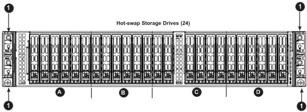
text_image
Hot-swap Storage Drives (24) 1 A B C D 1Figure 1-2. Chassis Front View
| Front Chassis Features | ||
| Item Feature | Description | |
| 1 Control Panels | Controls a node as labeled | |
| A Drive bays | Six drives controlled by node | A |
| B Drive bays | Six drives controlled by node | B |
| C Drive bays | Six drives controlled by node | C |
| D Drive bays | Six drives controlled by node | D |
Rear Features
The illustration below shows the features included on the rear of the chassis.
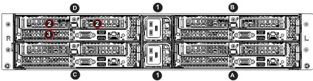
text_image
D 1 B 2 3 C 1 AFigure 1-3. Chassis Rear View
| Rear Chassis Features | ||
| Item Feature Description | ||
| A, B, C, D Node A, B, C, D Independent computing nodes | ||
| 1 Power Supplies Redundant power modules | ||
| 2 PCI Slots Two PCI-E 3.0 x16 slots in each node | ||
| 3 SIOM port | Network ports in each node; refer to table below for available SIOM cards | |
| Unlabeled I/O ports Described on next page and Chapter 4 | ||
| SIOM Networking Add-on Card Options | ||
| Speed Ports | Add-on Card Part Number | |
| GbE | Two RJ45 AOC-MGP-i2M | |
| Four RJ45 AOC-MGP-i4M | ||
| 10 G SFP+ | Two SFP+ AOC-MTGN-i2SM | |
| Four SFP+ AOC-MTG-i4SM | ||
| 10GBase-T | Two RJ45 AOC-MTG-i2TM | |
| 25GbE | Two SFP28 & two RJ45 | AOC-MH25G-m2S2TM |
| IB FDR | Two QSFP & two RJ45 | AOC-MHIBF-m2Q2GM |
| One QSFP & two RJ45 | AOC-MHIBF-m1Q2GM | |
Updates: https://www.supermicro.com/support/resources/AOC/AOC_Compatibility_SIOM.cfm
Input/Output Rear Panel
Each node provides the following input/output ports.
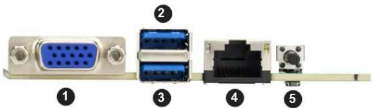
text_image
Diagram of electronic device ports with labeled connectors and connectorsFigure 1-4. I/O Panel
| Rear Panel I/O Ports | |||
| No. | Description No. | Description | |
| 1. VGA port 4. Dedicated BMC LAN | |||
| 2. USB1 (3.0) 5. Unit Identifier Switch | |||
| 3. USB0 (3.0) | |||
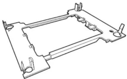
Node Trays
The chassis contains four separate computing node drawers, each with its own motherboard.
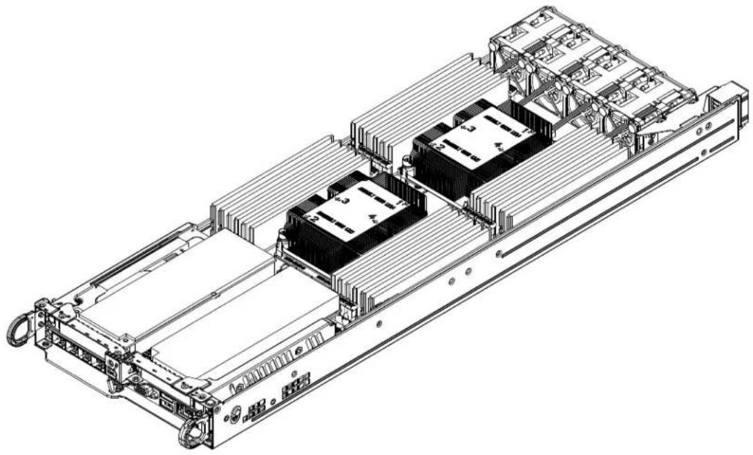
natural_image
Technical line drawing of a server rack with multiple internal components and mounting brackets (no text or symbols)Figure 1-5. Node Tray
1.5 Motherboard Layout
Below is a layout of the X11DPT-BH with jumper, connector and LED locations shown. See the table on the following page for descriptions. For detailed descriptions, pinout information and jumper settings, refer to Chapter 4.
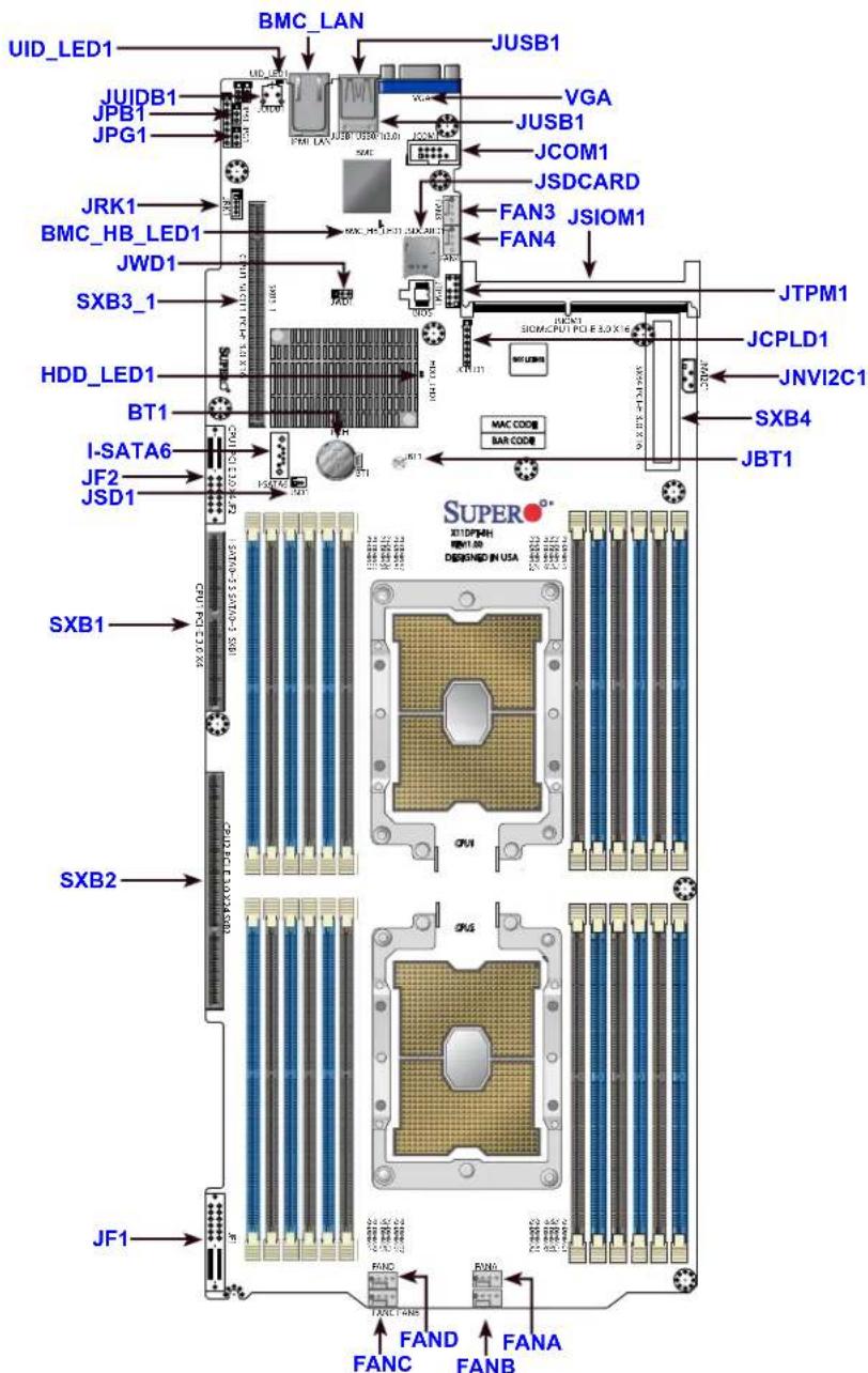
text_image
BMC_LAN UID_LED1 JUSB1 JUIDB1 JUSB1 JPB1 JCOM1 JPG1 JRCN JSDCARD JRK1 JSCI JSC3_1 JWD1 FAN3 JSIOM1 SXB3_1 JCPD1 HDD_LED1 JTPM1 BT1 JCPD2 JCPD3_1 JCPD4_1 JCPD5_1 JCPD6_1 JCPD7_1 JCPD8_1 JCPD9_1 JCPD10_1 JCPD11_1 JCPD12_1 JCPD13_1 JCPD14_1 JCPD15_1 JCPD16_1 JCPD17_1 JCPD18_1 JCPD19_1 JCPD20_1 JCPD21_1 JCPD22_1 JCPD23_1 JCPD24_1 JCPD25_1 JCPD26_1 JCPD27_1 JCPD28_1 JCPD29_1 JCPD30_1 JCPD31_1 JCPD32_1 JCPD33_1 JCPD34_1 JCPD35_1 JCPD36_1 JCPD37_1 JCPD38_1 JCPD39_1 JCPD40_1 JCPD41_1 JCPD42_1 JCPD43_1 JCPD44_1 JCPD45_1 JCPD46_1 JCPD47_1 JCPD48_1 JCPD49_1 JCPD50_1 JCPD51_1 JCPD52_1 JCPD53_1 JCPD54_1 JCPD55_1 JCPD56_1 JCPD57_1 JCPD58_1 JCPD59_1 JCPD60_1 JCPD61_1 JCPD62_1 JCPD63_1 JCPD64_1 JCPD65_1 JCPD66_1 JCPD67_1 JCPD68_1 JCPD69_1 JCPD70_1 JCPD71_1 JCPD72_1 JCPD73_1 JCPD74_1 JCPD75_1 JCPD76_1 JCPD77_1 JCPD78_1 JCPD79_1 JCPD80_1 JCPD81_1 JCPD82_1 JCPD83_1 JCPD84_1 JCPD85_1 JCPD86_1 JCPD87_1 JCPD88_1 JCPD89_1 JCPD90_1 JCPD91_1 JCPD92_1 JCPD93_1 JCPD94_1 JCPD95_1 JCPD96_1 JCPD97_1 JCPD98_1 JCPD99_1 JCPD00_1 JCP00A FANC FANB FANC FANB FANC FANB FANC FANB FANC FANB FANC FANB FANC FANB FANC FANB FANC FANB FANC FANB FANC FANB FANC FANB FANC FANB FANc FANb FANc FANb FANc FANb FANc FANb FANc FANb FANc FANb FANc FANb FANc FANb FANc FANb FANc FANb FANc FANb FANc FANb FANc FANb FANb FANc FANb FANc FANb FANc FANb FANc FANb FANc FANb FANc FANb FANc FANb FANc FANb FANc FANb FANc FANb FANc FANb FANc FANa FANb FANc FANb FANc FANb FANc FANb FANc FANb FANc FANb FANc FANb FANc FANb FANc FANb FANc FANb FANc FANb FANc FANb FANc FANc FANb FANc FANb FANc FANb FANc FANb FANc FANb FANc FANb FANc FANb FANc FANb FANc FANb FANc FANb FANc FANb FANc FANb FAN cFigure 1-6. Motherboard Layout
- "indicates the location of Pin 1."
- Jumpers/LED indicators not indicated are used for internal testing only.
Quick Reference
Jumper Description Default Setting
| JBT1 Clear CMOS Open (Normal) |
| JPME1 ME Recovery Pins 1-2 (Normal) |
| JWD1 Watch Dog Timer Enable Pins 1-2 (Normal) |
| JPG1 VGA Enable/Disable Pins 1-2 (Enabled) |
| JPB1 BMC Enable Pins 1-2 (Enabled) |
Connector Description
| Battery (BT1) Onboard CMOS battery | |
| JCOM1 COM port 1 | |
| FANA~FAND | System cooling fan headers |
| BMC_LAN | Dedicated BMC LAN port |
| JF1 | Front control panel header |
| JF2 | PCI-E 3.0 x4 slot (CPU1) |
| JNV1^2C1 | NVMe I^2C header |
| JRK1 | RAID Key for onboard NVMe devices |
| JSD1 | SATA DOM power connector |
| JSDCARD1 | Micro SD card slot (reserved for manufacturer use only) |
| JTPM1 | Trusted Platform Module (TPM)/Port 80 connector |
| SIOM1 | CPU1 PCI-E 3.0 x16 networking slot |
| SXB1 | PCI-E 3.0 (x4 + x4) slot supported by CPU1 and SATA connections (I-SATA0~5 & S-SATA0~5) |
| SXB2 | PCI-E 3.0 x24 (x16 + x8) slot for SMCI storage add-on card (AOC) |
| SXB3_1 | PCI-E 3.0 x16 left hand riser slot supported by CPU1 |
| SXB4 | PCI-E 3.0 x16 right hand riser slot supported by CPU2 |
| I-SATA0~5 | I-SATA 3.0 connectors supported by the Intel PCH |
| S-SATA0~5 | S-SATA 3.0 connectors supported by the Intel PCH |
| I-SATA6 | SATADOM power |
| UID-SW | UID switch |
| USB0/1 | Back panel USB 3.0 ports |
| VGA | Back panel VGA port |
LED Description
State Status
| BMC_HB_LED1 | BMC Heartbeat LED | Green: Blinking | BMC Normal |
| HDD_LED1 | HDD Activity LED | Green: Blinking | HDD Normal |
| UID_LED1 | Rear UID LED | Blue: On | Unit Identified |
System Block Diagram

flowchart
graph TD
    A["Intel PCH"] -->|PCI-E X1| B["SIOM"]
    A -->|PCI-E X3| C["SMI"]
    A -->|PCI-E X4 | D["PCI-E X4 #3C"]
    A -->|PCI-E X5 | E["PCI-E X5 #3D"]
    A -->|PCI-E X6 | F["PCI-E X6 #3C"]
    A -->|PCI-E X7 | G["PCI-E X7 #3C"]
    A -->|PCI-E X8 | H["PCI-E X8 #3C"]
    A -->|PCI-E X9 | I["PCI-E X9 #3C"]
    A -->|PCI-E X10 | J["PCI-E X10 #3C"]
    A -->|PCI-E X11 | K["PCI-E X11 #3C"]
    A -->|PCI-E X12 | L["PCI-E X12 #3C"]
    A -->|PCI-E X13 | M["PCI-E X13 #3C"]
    A -->|PCI-E X14 | N["PCI-E X14 #3C"]
    A -->|PCI-E X15 | O["PCI-E X15 #3C"]
    A -->|PCI-E X16 | P["PCI-E X16 #3C"]
    A -->|PCI-E X17 | Q["PCI-E X17 #3C"]
    A -->|PCI-E X18 | R["PCI-E X18 #3C"]
    A -->|PCI-E X19 | S["PCI-E X19 #3C"]
    A -->|PCI-E X20 | T["PCI-E X20 #3C"]
    A -->|PCI-E X21 | U["PCI-E X21 #3C"]
    A -->|PCI-E X22 | V["PCI-E X22 #3C"]
    A -->|PCI-E X23 | W["PCI-E X23 #3C"]
    A -->|PCI-E X24 | X["PCI-E X24 #3C"]
    A -->|PCI-E X25 | Y["PCI-E X25 #3C"]
    A -->|PCI-E X26 | Z["PCI-E X26 #3C"]
    A -->|PCI-E X27 | AA["PCI-E X27 #3C"]
    A -->|PCI-E X28 | AB["PCI-E X28 #3C"]
    A -->|PCI-E X29 | AC["PCI-E X29 #3C"]
    A -->|PCI-E X30 | AD["PCI-E X30 #3C"]
    A -->|PCI-E X31 | AE["PCI-E X31 #3C"]
    A -->|PCI-E X32 | AF["PCI-E X32 #3C"]
    A -->|PCI-E X33 | AG["PCI-E X33 #3C"]
    A -->|PCI-E X34 | AH["PCI-E X34 #3C"]
    A -->|PCI-E X35 | AI["PCI-E X35 #3C"]
    A -->|PCI-E X36 | AJ["PCI-E X36 #3C"]
    A -->|PCI-E X37 | AK["PCI-E X37 #3C"]
    A -->|PCI-E X38 | AL["PCI-E X38 #3C"]
    A -->|PCI-E X39 | AM["PCI-E X39 #3C"]
    A -->|PCI-E X40 | AN["PCI-E X40 #3C"]
    A -->|PCI-E X41 | AO["PCI-E X41 #3C"]
    A -->|PCI-E X42 | AP["PCI-E X42 #3C"]
    A -->|PCI-E X43 | AQ["PCI-E X43 #3C"]
    A -->|PCI-E X44 | AR["PCI-E X44 #3C"]
    A -->|PCI-E X45 | AS["PCI-E X45 #3C"]
    A -->|PCI-E X46 | AT["PCI-E X46 #3C"]
    A -->|PCI-E X47 | AU["PCI-E X47 #3C"]
    A -->|PCI-E X48 | AV["PCI-E X48 #3C"]
    A -->|PCI-E X49 | AW["PCI-E X49 #3C"]
    A -->|PCI-E X50 | AX["PCI-E X50 #3C"]
    A -->|PCI-E X51 | AY["PCI-E X51 #3C"]
    A -->|PCI-E X52 | AZ["PCI-E X52 #3C"]
    A -->|PCI-E X53 | BA["PCI-E X53 #3C"]
    A -->|PCI-E X54 | BB["PCI-E X54 #3C"]
    A -->|PCI-E X55 | BC["PCI-E X55 #3C"]
    A -->|PCI-E X56 | BD["PCI-E X56 #3C"]
    A -->|PCI-E X57 | BE["PCI-E X57 #3C"]
    A -->|PCI-E X58 | BF["PCI-E X58 #3C"]
    A -->|PCI-E X59 | BG["PCI-E X59 #3C"]
    A -->|PCI-E X60 | BH["PCI-E X60 #3C"]
    A -->|PCI-E X61 | BI["PCI-E X61 #3C"]
    A -->|PCI-E X62 | BJ["PCI-E X62 #3C"]
    A -->|PCI-E X63 | BK["PCI-E X63 #3C"]
    A -->|PCI-E X64 | BL["PCI-E X64 #3C"]
    A -->|PCI-E X65 | BM["PCI-E X65 #3C"]
    A -->|PCI-E X66 | BN["PCI-E X66 #3C"]
    A -->|PCI-E X67 | BO["PCI-E X67 #3C"]
    A -->|PCI-E X68 | BP["PCI-E X68 #3C"]
    A -->|PCI-E X69 | BQ["PCI-E X69 #3C"]
    A -->|PCI-E X70 | BR["PCI-E X70 #3C"]
    A -->|PCI-E X71 | BS["PCI-E X71 #3C"]
    A -->|PCI-E X72 | BT["PCI-E X72 #3C"]
    A -->|PCI-E X73 | BU["PCI-E X73 #3C"]
    A -->|PCI-E X74 | BV["PCI-E X74 #3C"]
    A -->|PCI-E X75 | BW["PCI-E X75 #3C"]
    A -->|PCI-E X76 | BX["PCI-E X76 #3C"]
    A -->|PCI-E X77 | BY["PCI-E X77 #3C"]
    A -->|PCI-E X78 | BZ["PCI-E X78 #3C"]
    A -->|PCI-E X79 | CA["PCI-E X79 #3C"]
    A -->|PCI-E X80 | CB["PCI-E X80 #3C"]
Figure 1-7. SYS-2029BZ-HNR System Block Diagram
1.6 Where to Get Replacement Components
If you need replacement parts for your system, to ensure the highest level of professional service and technical support, purchase exclusively from our Supermicro Authorized Distributors/System Integrators/Resellers. A list can be found at: http://www.supermicro.com. Click the "Where to Buy" link.
1.7 Returning Merchandise for Service
A receipt or copy of your invoice marked with the date of purchase is required before any warranty service will be rendered. You can obtain service by calling your vendor for a Returned Merchandise Authorization (RMA) number. When returning to the manufacturer, the RMA number should be prominently displayed on the outside of the shipping carton, and mailed prepaid or hand-carried. Shipping and handling charges will be applied for all orders that must be mailed when service is complete.
For faster service, RMA authorizations may be requested online (http://www.supermicro.com/support/rma/).
Whenever possible, repack the chassis in the original Supermicro carton, using the original packaging material. If these are no longer available, be sure to pack the chassis securely, using packaging material to surround the chassis so that it does not shift within the carton and become damaged during shipping.
This warranty only covers normal consumer use and does not cover damages incurred in shipping or from failure due to the alteration, misuse, abuse or improper maintenance of products.
During the warranty period, contact your distributor first for any product problems.
Chapter 2
Server Installation
2.1 Overview
This chapter provides advice and instructions for mounting your system in a server rack. If your system is not already fully integrated with processors, system memory etc., refer to Chapter 4 for details on installing those specific components.
Caution: Electrostatic Discharge (ESD) can damage electronic components. To prevent such damage to PCBs (printed circuit boards), it is important to use a grounded wrist strap, handle all PCBs by their edges and keep them in anti-static bags when not in use.
2.2 Preparing for Setup
The box in which the system was shipped should include the rackmount hardware needed to install it into the rack. Please read this section in its entirety before you begin the installation.
Choosing a Setup Location
- The system should be situated in a clean, dust-free area that is well ventilated. Avoid areas where heat, electrical noise and electromagnetic fields are generated.
- Leave enough clearance in front of the rack so that you can open the front door completely (\~25 inches) and approximately 30 inches of clearance in the back of the rack to allow sufficient space for airflow and access when servicing.
- This product should be installed only in a Restricted Access Location (dedicated equipment rooms, service closets, etc.).
- This product is not suitable for use with visual display workplace devices according to §2 of the German Ordinance for Work with Visual Display Units.
Rack Precautions
- Ensure that the leveling jacks on the bottom of the rack are extended to the floor so that the full weight of the rack rests on them.
- In single rack installations, stabilizers should be attached to the rack. In multiple rack installations, the racks should be coupled together.
- Always make sure the rack is stable before extending a server or other component from the rack.
- You should extend only one server or component at a time - extending two or more simultaneously may cause the rack to become unstable.
Server Precautions
- Review the electrical and general safety precautions in Appendix B.
- Determine the placement of each component in the rack before you install the rails.
- Install the heaviest server components at the bottom of the rack first and then work your way up.
- Use a regulating uninterruptible power supply (UPS) to protect the server from power surges and voltage spikes and to keep your system operating in case of a power failure.
- Allow any drives and power supply modules to cool before touching them.
- When not servicing, always keep the front door of the rack and all covers/panels on the servers closed to maintain proper cooling.
Rack Mounting Considerations
Ambient Operating Temperature
If installed in a closed or multi-unit rack assembly, the ambient operating temperature of the rack environment may be greater than the room's ambient temperature. Therefore, consideration should be given to installing the equipment in an environment compatible with the manufacturer's maximum rated ambient temperature (TMRA).
Airflow
Equipment should be mounted into a rack so that the amount of airflow required for safe operation is not compromised.
Mechanical Loading
Equipment should be mounted into a rack so that a hazardous condition does not arise due to uneven mechanical loading.
Circuit Overloading
Consideration should be given to the connection of the equipment to the power supply circuitry and the effect that any possible overloading of circuits might have on overcurrent protection and power supply wiring. Appropriate consideration of equipment nameplate ratings should be used when addressing this concern.
Reliable Ground
A reliable ground must be maintained at all times. To ensure this, the rack itself should be grounded. Particular attention should be given to power supply connections other than the direct connections to the branch circuit (i.e. the use of power strips, etc.).

To prevent bodily injury when mounting or servicing this unit in a rack, you must take special precautions to ensure that the system remains stable. The following guidelines are provided to ensure your safety:
- This unit should be mounted at the bottom of the rack if it is the only unit in the rack.
- When mounting this unit in a partially filled rack, load the rack from the bottom to the top with the heaviest component at the bottom of the rack.
- If the rack is provided with stabilizing devices, install the stabilizers before mounting or servicing the unit in the rack.
- Slide rail mounted equipment is not to be used as a shelf or a work space.
2.3 Rack Mounting Instructions
This section provides information on installing the chassis into a rack unit with the rails provided. There are a variety of rack units on the market, which may mean that the assembly procedure will differ slightly from the instructions provided. You should also refer to the installation instructions that came with the rack unit you are using. Note: This rail will fit a rack between 28" and 33.5" deep.
Overview of the Rack Rails
The package includes two rail assemblies. Each is specifically designed for the left or right side of the chassis, and so marked. Each rail consists of two sections: a front section which secures to the front post of the rack and a rear section which adjusts in length and secures to the rear post of the rack.
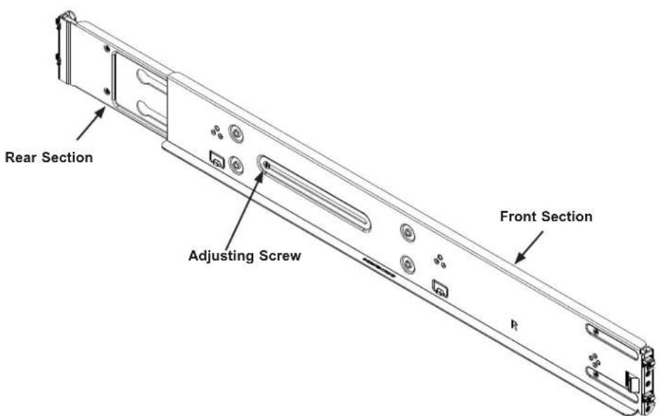
text_image
Rear Section Adjusting Screw Front SectionFigure 2-1. Rackmount Rail (Right rail assembly shown)
Adjusting the Rail Length
Each rail assembly has a locking screw to adjust the length of the rail to fit the depth of your rack.
Installing the Rails on a Rack
- Loosen the adjusting screw to allow the rear section to slide into the front section.
- Push the small hooks on the front section of the rail into the holes on the front post of the rack and then down, until the spring-loaded pegs snap into the rack holes. Secure the rail to the rack with screws.
- Pull out the rear section of the outer rail, adjusting the length until it fits within the posts of the rack and align the small hooks with the appropriate holes on the rear post of the rack. Be sure the rail is level, then mount the rear section onto the rack. Secure the rail with screws.
- Tighten the adjusting screw.

natural_image
Technical line drawing of a server rack with labeled components (no text or symbols)Figure 2-2. Attaching the Rail Front to the Rack (Left rail shown)
Note: Figures are for illustrative purposes only. Always install servers into racks from the bottom up.
Chassis Installation
Slide the chassis into the rack so that the bottom of the chassis slides onto the bottom lip of the rails.
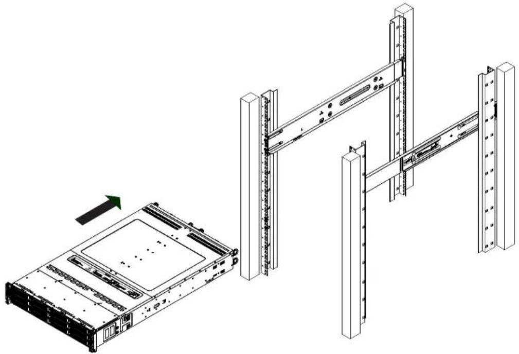
natural_image
Technical line drawing of a server rack with an attached drive unit and a green arrow indicating direction (no text or symbols)Figure 2-3. Sliding the Chassis into the Rack
Note: Figures are for illustrative purposes only. Always install servers into racks from the bottom up.

Stability hazard. The rack stabilizing mechanism must be in place, or the rack must be bolted to the floor before you slide the unit out for servicing. Failure to stabilize the rack can cause the rack to tip over.
Chapter 3
Maintenance and Component Installation
This chapter provides instructions on installing and replacing main system components. To prevent compatibility issues, only use components that match the specifications and/or part numbers given.
Installation or replacement of most components require that power first be removed from the system. Please follow the procedures given in each section.
3.1 Removing Power
Before performing some setup or maintenance tasks, use the following procedure to ensure that power has been removed from the system.
Removing Power from a Node
- Use the operating system to power down the node.
- Grasp the head of the power cord and gently pull it out of the back of the power supply.
Removing Power from the System
- Use the operating system to power down all nodes.
- Grasp the head of each power cord and gently pull it out of the back of the power supply.
- Disconnect the cords from the power strip or wall outlet.
3.2 Accessing the System
Removing a Computing Node Drawer
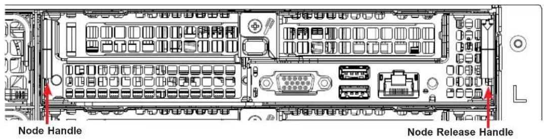
text_image
Node Handle Node Release HandleFigure 3-1. Removing a Node Tray
Removing a Node
- Use the operating system to power down the node.
- Remove any cables attached to the node
- Pull down the node release handle and use both handles to slide the node out the chassis rear.
Removing the Chassis Cover
You can access some chassis components, such as fans, by removing the cover.

text_image
Remove two screwsFigure 3-2. Removing the Chassis Cover
Removing the Chassis Cover
The chassis top cover can be lifted off after removing two screws.
Caution: Except for short periods of time, do not operate the server without the cover in place. It provides proper airflow to prevent overheating.
3.3 Motherboard Components
Processor and Heatsink Installation
The processor (CPU) and processor carrier should be assembled together first to form the processor carrier assembly. This will be attached to the heatsink to form the processor heatsink module (PHM) before being installed onto the CPU socket.
Notes:
- Use ESD protection.
- Unplug the AC power cord from all power supplies after shutting down the system.
- Check that the plastic protective cover is on the CPU socket and none of the socket pins are bent. If they are, contact your retailer.
- When handling the processor, avoid touching or placing direct pressure on the LGA lands (gold contacts). Improper installation or socket misalignment can cause serious damage to the processor or CPU socket, which may require manufacturer repairs.
- Thermal grease is pre-applied on a new heatsink. No additional thermal grease is needed.
• Refer to the Supermicro website for updates on processor support. - All graphics in this manual are for illustration only. Your components may look different.
The Processor
The Intel Xeon 82xx/62xx/52xx/42xx/32xx or 81xx/61xx/51xx/41xx/31xx processor series comes in two models: Fabric (F Model) and Non-Fabric (Non-F Model). Only the Non-Fabric model is supported for this system.
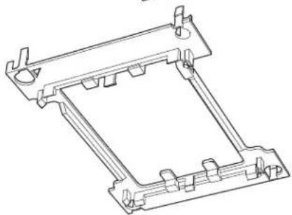
The Processor Carrier Assembly
The assembly is the processor and a plastic carrier.

natural_image
Technical line drawing of a rectangular electronic component or enclosure with mounting holes and internal structure (no text or symbols)Processor
natural_image
Technical line drawing of a mechanical bracket or frame structure (no text or symbols)Processor Carrier
Heatsinks
The 2029BZ-HNR server uses a slightly different heatsink design for each CPU. The SNK-P0067PSMB model is used for CPU2, the CPU closer to the mid-chassis fans.
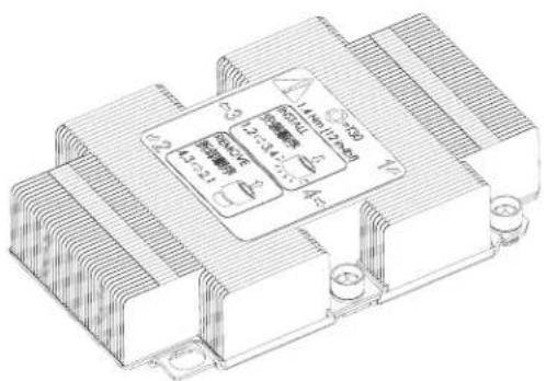
natural_image
Technical line drawing of a heat exchanger or cooling unit with cooling fins and cooling elements (no text or symbols)Figure 3-3. Heatsink SNK-P0071-VS (for CPU1)

text_image
SNK-F06 TPSMB VYPRM871Figure 3-4. Heatsink SNK-P0067PSMB (for CPU2)
Overview of the Processor Heatsink Module
The Processor Heatsink Module (PHM) contains a heatsink, a processor carrier, and the processor.
Heatsink with Thermal Grease
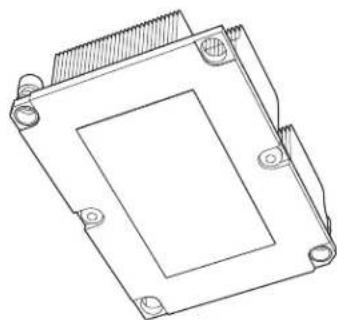
natural_image
Technical line drawing of a mechanical component with mounting holes and a central square housing (no text or symbols)Processor Carrier
natural_image
Technical line drawing of a mechanical bracket or mounting frame (no text or symbols)Processor
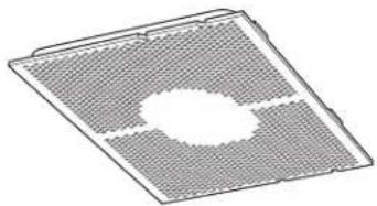
natural_image
3D diagram of a square grid with a central oval cutout and a horizontal line, no text or symbols present.Processor Heatsink Module


natural_image
Technical line drawing of a computer processor cooling module (no text or symbols)Bottom View
Creating the Processor Carrier Assembly
To install a processor into the processor carrier, follow the steps below:
- Hold the processor with the LGA lands (gold contacts) facing up. Locate the small, gold triangle in the corner of the processor and the corresponding hollowed triangle on the processor carrier. These triangles indicate pin 1. See the images below.
- Using the triangles as a guide, carefully align and place Point A of the processor into Point A of the carrier. Then gently flex the other side of the carrier for the processor to fit into Point B.
- Examine all corners to ensure that the processor is firmly attached to the carrier.

flowchart
graph TD
    A["CPU (Upside Down) with CPU LGA Lands up"] --> B["Pin 1"]
    B --> C["Align Point A of the CPU and Point A of the Processor Carrier"]
    B --> D["Align Point B of the CPU and Point B of the Processor Carrier"]
    B --> E["Processor Carrier (Upside Down)"]
    F["Align CPU Pin 1"] --> G["Pin 1"]
    G --> H["Pin 2"]

text_image
Allow carrier to latch onto CPU A B Allow carrier to latch onto CPU Pin 1Processor Carrier Assembly
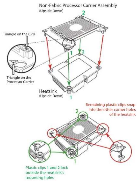
Assembling the Processor Heatsink Module
After creating the processor carrier assembly, mount it onto the heatsink to create the processor heatsink module (PHM):
-
Note the label on top of the heatsink, which marks the heatsink mounting holes as 1, 2, 3, and 4. If this is a new heatsink, the thermal grease has been pre-applied on the underside. Otherwise, apply the proper amount of thermal grease.
-
Turn the heatsink over with the thermal grease facing up. Hold the processor carrier assembly so the processor's gold contacts are facing up, then align the triangle on the assembly with hole 1 of the heatsink. Press the processor carrier assembly down. The plastic clips of the assembly will lock outside of holes 1 and 2, while the remaining clips will snap into their corresponding holes.
-
Examine all corners to ensure that the plastic clips on the processor carrier assembly are firmly attached to the heatsink.
text_image
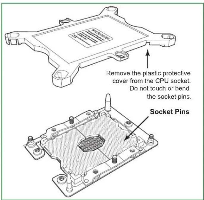
Non-Fabric Processor Carrier Assembly (Upside Down) Triangle on the CPU Triangle on the Processor Carrier Heatsink (Upside Down) Remaining plastic clips snap into the other corner holes of the heatsink Plastic clips 1 and 2 lock outside the heatsink's mounting holesPreparing the CPU Socket for Installation
This motherboard comes with a plastic protective cover on the CPU socket. Remove it carefully to install the Processor Heatsink Module (PHM).

natural_image
Technical line drawing of a computer processor casing with visible pins and a warning label (no text or symbols beyond the warning label)CPU Socket with Plastic Protective Cover
text_image
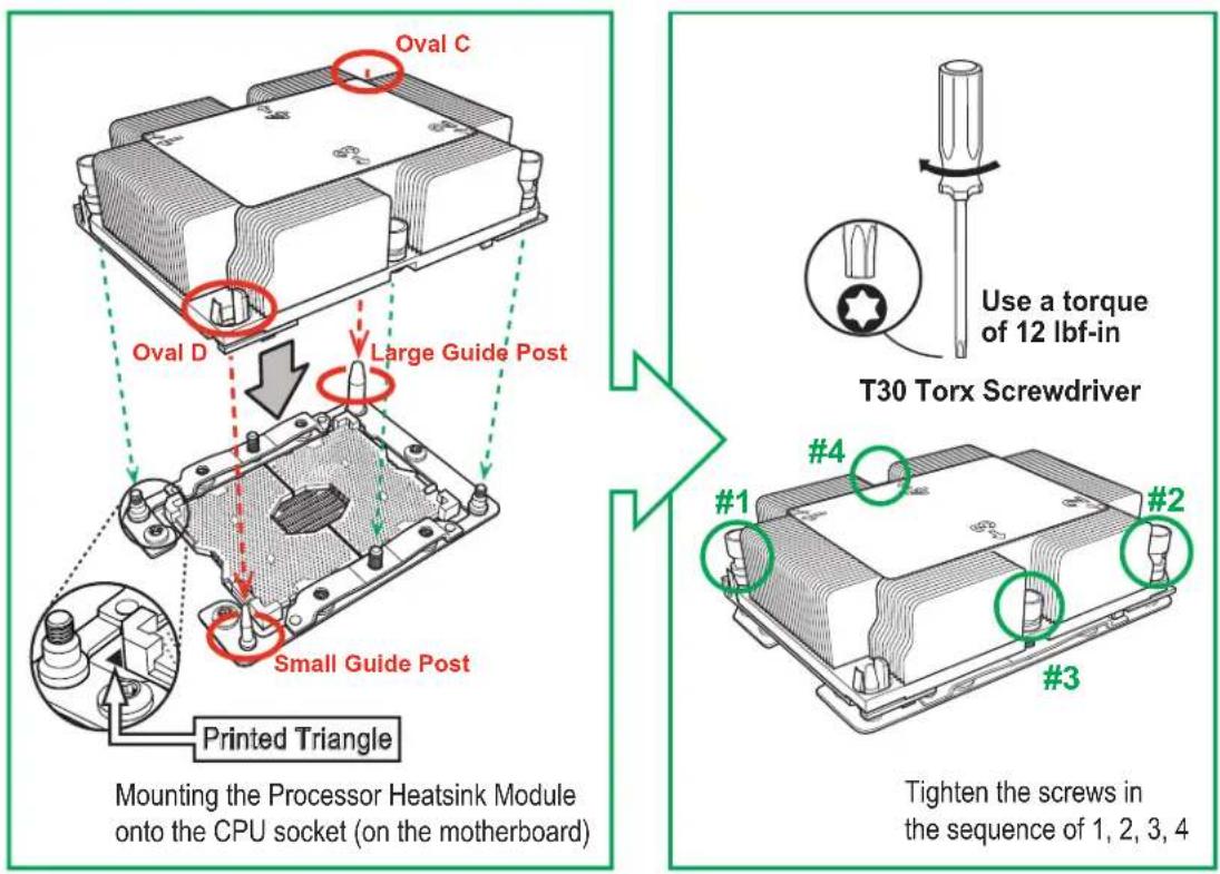
WARNING Remove the plastic protective cover from the CPU socket. Do not touch or bend the socket pins. Socket PinsInstalling the Processor Heatsink Module
After assembling the Processor Heatsink Module (PHM), install it onto the CPU socket:
- Align hole 1 of the heatsink with the printed triangle on the CPU socket. See the left image below.
- Make sure all four holes of the heatsink are aligned with the socket before gently placing the heatsink on top.
- With a T30 Torx-bit screwdriver, gradually tighten screws #1 – #4 to assure even pressure. The order of the screws is shown on the label on top of the heatsink. To avoid damaging the processor or socket, do not use a force greater than 12 lbf-in when tightening the screws.
- Examine all corners to ensure that the PHM is firmly attached to the socket.
text_image
Oval C Oval D Large Guide Post Small Guide Post Printed Triangle Mounting the Processor Heatsink Module onto the CPU socket (on the motherboard) T30 Torx Screwdriver Use a torque of 12 lbf-in #1 #2 #3 Tighten the screws in the sequence of 1, 2, 3, 4If at any time the PHM must be removed, power off, then loosen the screws in the sequence of #4, #3, #2, and #1.
Memory Installation
Memory Support
The X11DPT-BH supports up to 24 DIMM slots for up to 6 TB of memory with DDR4 ECC Load Reduced DIMMs (LRDIMM) and Registered DIMMs (RDIMM). In addition it supports Non-Volatile DIMMs (NVDIMM) and Intel Optane DC Persistent Memory (DCPMM; up to four slots).
| DDR4 Memory Support for 81xx/61xx/51xx/41xx/31xx Processors | ||||||
| Type | Ranks Per DIMM and Data Width | DIMM Capacity (GB) | Speed (MT/s) | |||
| One Slot per Channel | Two Slots per Channel | |||||
| DRAM Density | One DIMM per Channel | One DIMM per Channel | Two DIMMs per Channel | |||
| 4 Gb 8 Gb 1.2 Volts 1.2 Volts 1.2 Volts | ||||||
| RDIMM | SRx4 4 GB | 8 GB | 2666 2666 2666 | |||
| SRx8 8 GB | 16 GB | |||||
| DRx8 8 GB | 16 GB | |||||
| DRx4 16 GB | 32 GB | |||||
| RDIMM 3Ds | QRX4 N/A | 2H-64GB | ||||
| 8RX4 N/A | 4H-128GB | |||||
| LRDIMM QRx4 | 32 GB 64 GB | |||||
| LRDIMM 3Ds | QRx4 N/A | 2H-64GB | ||||
| 8Rx4 N/A | 4H-128 GB | |||||
| DDR4 Memory Support for 82xx/62xx/52xx/42xx/32xx Processors | |||||||
| Type | Ranks Per DIMM and Data Width | DIMM Capacity (GB) | Speed (MT/s) | ||||
| One Slot per Channel | Two Slots per Channel | ||||||
| DRAM Density | One DIMM per Channel | One DIMM per Channel | Two DIMMs per Channel | ||||
| 4 Gb* | 8 Gb | 16 Gb | 1.2 Volts | Volts 1.2 Volts | |||
| RDIMM | SRx4 4 GB | 8 GB | 16 GB | 2933** | 2933* | 2933* | |
| SRx8 8 GB | 16 GB | 32 GB | |||||
| DRx8 8 GB | 16 GB | 32 GB | |||||
| DRx4 16 GB | 32 GB | 64 GB | |||||
| RDIMM 3Ds | QRX4 | N/A | 2H-64GB | 2H-128GB | |||
| 8RX4 N/A | 4H-128GB | 4H-256GB | |||||
| LRDIMM | QRx4 | 32 GB | 64 GB | 128 GB | |||
| LRDIMM 3Ds | QRx4 | N/A | 2H-64GB | 2H-64GB | |||
| 8Rx4 N/A | 4H-128 GB | 4H-256 GB | |||||
*4Gb DRAM density is only supported on speeds up to 2666 MT/s
**Only the 82xx and 62xx series support 2933 MT/s; for other processors, memory speed as supported by the CPU.
Check the Supermicro website for possible updates to memory support.
Memory Population Guidelines
• All DIMMs must be DDR4.
- Balance memory. Using unbalanced memory topology, such as populating two DIMMs in one channel while populating one DIMM in another channel, reduces performance. It is not recommended for Supermicro systems.
- In dual-CPU configurations, memory must be installed in the slots associated with the installed CPUs.
Guidelines Regarding Mixing DIMMs
- Populating slots with a pair of DIMM modules of the same type and size results in interleaved memory, which improves memory performance.
- Use memory modules of the same type and speed, as mixing is not allowed.
- x4 and x8 DIMMs can be mixed in the same channel.
- Mixing of LRDIMMs and RDIMMs is not allowed in the same channel, across different channels, and across different sockets.
- Mixing of non-3DS and 3DS LRDIMM is not allowed in the same channel, across different channels, and across different sockets.
DIMM Construction
- RDIMM (non-3DS) Raw Cards: A/B (2Rx4), C (1Rx4), D (1Rx8), E (2Rx8)
• 3DS RDIMM Raw Cards: A/B (4Rx4)
• LRDIMM (non-3DS) Raw Cards: D/E (4Rx4)
• 3DS LRDIMM Raw Cards: A/B (8Rx4)
Memory Population Sequence
Blue slots versus black slots: Install the first DIMM in the blue memory slot, which is the first of a memory channel. Then, if using two DIMMs per channel, install the second DIMM in the black slot.
The following memory population sequence table was created based on guidelines provided by Intel to support Supermicro motherboards. The diagram is for illustrative purposes; your motherboard may look different.
| Memory Population for the X11 DP Motherboard, 24 DIMM Slots | |
| CPUs/DIMMs Memory Population Sequence | |
| 1 CPU & 1 DIMM CPU1: P1-DIMMA1 | |
| 1 CPU & 2 DIMMs CPU1: P1-DIMMA1/P1-DIMMD1 | |
| 1 CPU & 3 DIMMs CPU1: P1-DIMMC1/P1-DIMMB1/P1-DIMMA1 | |
| 1 CPU & 4 DIMMs CPU1: P1-DIMMB1/P1-DIMMA1/P1-DIMMD1/P1-DIMME1 | |
| 1 CPU & 5 DIMMs* CPU1: P1-DIMMC1/P1-DIMMB1/P1-DIMMA1/P1-DIMMD1/P1-DIMME1 | |
| 1 CPU & 6 DIMM CPU1: P1-DIMMC1/P1-DIMMB1/P1-DIMMA1/P1-DIMMD1/P1-DIMME1/P1-DIMMF1 | |
| 1 CPU & 7 DIMMs* | CPU1: P1-DIMMB1/P1-DIMMB2/P1-DIMMA1/P1-DIMMA2/P1-DIMMD1/P1-DIMME1/P1-DIMMF1 |
| 1 CPU & 8 DIMMs | CPU1: P1-DIMMB1/P1-DIMMB2/P1-DIMMA1/P1-DIMMA2/P1-DIMMD2/P1-DIMMD1/P1-DIMME2/P1-DIMME1 |
| 1 CPU & 9 DIMMs* | CPU1: P1-DIMMC1/P1-DIMMC2/P1-DIMMB1/P1-DIMMB2/P1-DIMMA1/P1-DIMMA2/P1-DIMMD1/P1-DIMME1/P1-DIMMF1 |
| 1 CPU & 10 DIMMs* | CPU1: P1-DIMMC1/P1-DIMMB1/P1-DIMMB2/P1-DIMMA1/P1-DIMMA2/P1-DIMMD2/P1-DIMMD1/P1-DIMME2/P1-DIMME1/P1-DIMMF1 |
| 1 CPU & 11 DIMMs* | CPU1: P1-DIMMC1/P1-DIMMC2/P1-DIMMB1/P1-DIMMB2/P1-DIMMA1/P1-DIMMA2/P1-DIMMD2/P1-DIMMD1/P1-DIMME2/P1-DIMME1/P1-DIMMF1 |
| 1 CPU & 12 DIMMs | CPU1: P1-DIMMC1/P1-DIMMC2/P1-DIMMB1/P1-DIMMB2/P1-DIMMA1/P1-DIMMA2/P1-DIMMD2/P1-DIMMD1/P1-DIMME2/P1-DIMME1/P1-DIMMF2/P1-DIMMF1 |
| 2 CPUs & 2 DIMMs | CPU1: P1-DIMMA1CPU2: P2-DIMMA1 |
| 2 CPUs & 4 DIMMs | CPU1: P1-DIMMA1/P1-DIMMD1CPU2: P2-DIMMA1/P2-DIMMD1 |
| 2 CPUs & 6 DIMMs | CPU1: P1-DIMMC1/P1-DIMMB1/P1-DIMMA1CPU2: P2-DIMMC1/P2-DIMMB1/P2-DIMMA1 |
| 2 CPUs & 8 DIMMs | CPU1: P1-DIMMB1/P1-DIMMA1/P1-DIMMD1/P1-DIMME1CPU2: P2-DIMMB1/P2-DIMMA1/P2-DIMMD1/P2-DIMME1 |
| 2 CPUs & 10 DIMMs | CPU1: P1-DIMMC1/P1-DIMMB1/P1-DIMMA1/P1-DIMMD1/P1-DIMME1/P1-DIMMF1CPU2: P2-DIMMB1/P2-DIMMA1/P2-DIMMD1/P2-DIMME1 |
| 2 CPUs & 12 DIMMs | CPU1: P1-DIMMC1/P1-DIMMB1/P1-DIMMA1/P1-DIMMD1/P1-DIMME1/P1-DIMMF1CPU2: P2-DIMMC1/P2-DIMMB1/P2-DIMMA1/P2-DIMMD1/P2-DIMME1/P2-DIMMF1 |
| 2 CPUs & 14 DIMMs | CPU1: P1-DIMMB1/P1-DIMMB2/P1-DIMMA1/P1-DIMMA2/P1-DIMMD2/P1-DIMMD1/P1-DIMME2/P1-DIMME1CPU2: P2-DIMMC1/P2-DIMMB1/P2-DIMMA1/P2-DIMMD1/P2-DIMME1/P2-DIMMF1 |
| 2 CPUs & 16 DIMMs | CPU1: P1-DIMMB1/P1-DIMMB2/P1-DIMMA1/P1-DIMMA2/P1-DIMMD2/P1-DIMMD1/P1-DIMME2/P1-DIMME1CPU2: P2-DIMMB1/P2-DIMMB2/P2-DIMMA1/P2-DIMMA2/P2-DIMMD2/P2-DIMMD1/P2-DIMME2/P2-DIMME1 |
| 2 CPUs & 18 DIMMs | CPU1: P1-DIMMC1/P1-DIMMC2/P1-DIMMB1/P1-DIMMB2/P1-DIMMA1/P1-DIMMA2/P1-DIMMD2/P1-DIMMD1/P1-DIMME2/P1-DIMME1/P1-DIMMF2/P1-DIMMF1CPU2: P2-DIMMC1/P2-DIMMB1/P2-DIMMA1/P2-DIMMD1/P2-DIMME1/P2-DIMMF1 |
| 2 CPUs & 20 DIMMs | CPU1: P1-DIMMC1/P1-DIMMC2/P1-DIMMB1/P1-DIMMB2/P1-DIMMA1/P1-DIMMA2/P1-DIMMD2/P1-DIMMD1/P1-DIMME2/P1-DIMME1/P1-DIMMF2/P1-DIMMF1CPU2: P2-DIMMB1/P2-DIMMB2/P2-DIMMA1/P2-DIMMA2/P2-DIMMD2/P2-DIMMD1/P2-DIMME2/P2-DIMME1 |
| 2 CPUs & 22 DIMMs* | CPU1: P1-DIMMC1/P1-DIMMC2/P1-DIMMB1/P1-DIMMB2/P1-DIMMA1/P1-DIMMA2/P1-DIMMD2/P1-DIMMD1/P1-DIMME2/P1-DIMME1/P1-DIMMF1CPU2: P2-DIMMC1/P2-DIMMC2/P2-DIMMB1/P2-DIMMB2/P2-DIMMA1/P2-DIMMA2/P2-DIMMD2/P2-DIMMD1/P2-DIMME2/P2-DIMME1/P2-DIMMF1 |
| 2 CPUs & 24 DIMMs | CPU1: all slotsCPU2: all slots |
*Unbalanced, not recommended.
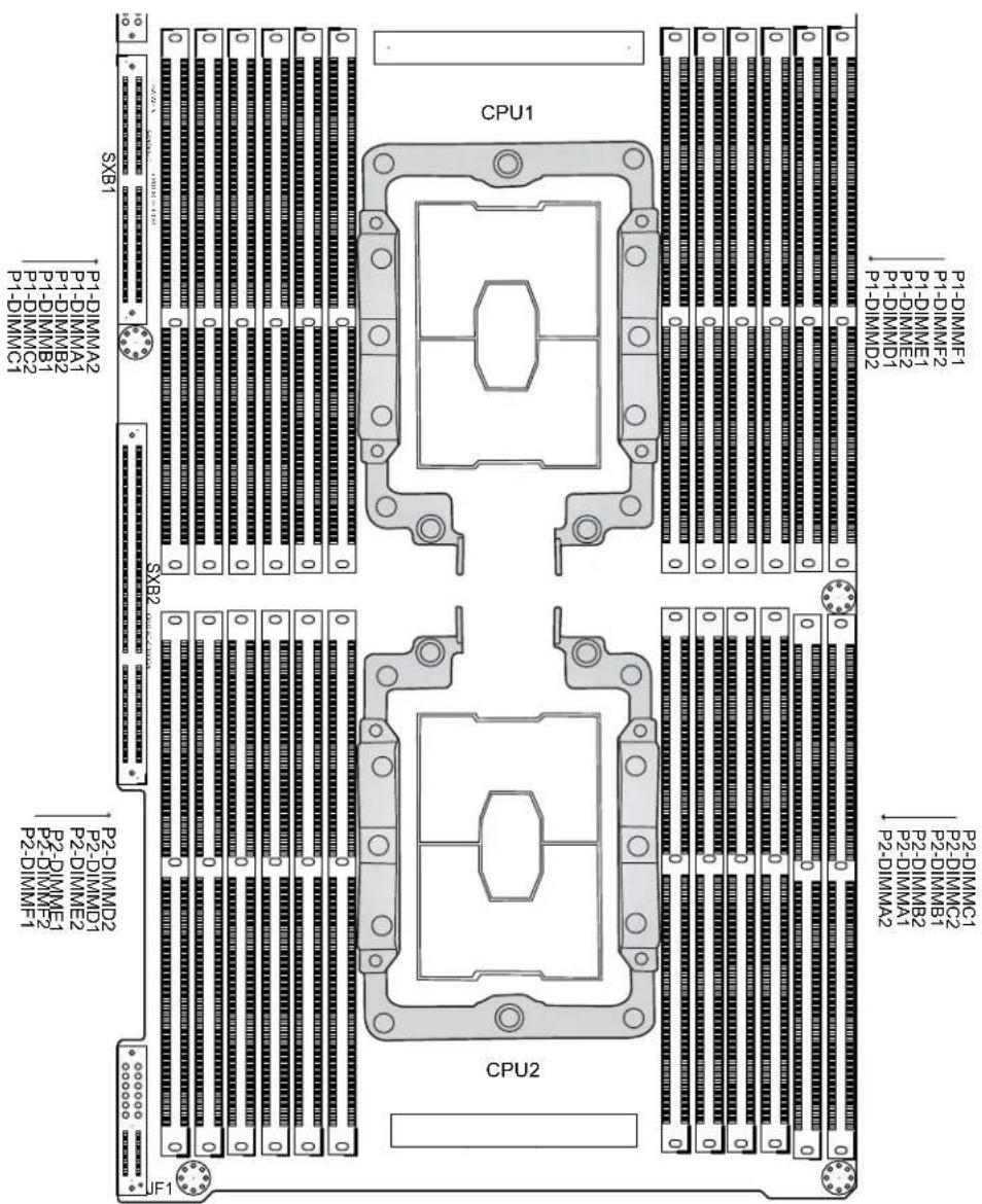
text_image
P1-DIMM01 P1-DIMM02 P1-DIMM03 P1-DIMM04 P1-DIMM05 P1-DIMM06 P1-DIMM07 P1-DIMM08 P1-DIMM09 P1-DIMM10 P1-DIMM11 P1-DIMM12 P1-DIMM13 P1-DIMM14 P1-DIMM15 P1-DIMM16 P1-DIMM17 P1-DIMM18 P1-DIMM19 P1-DIMM20 P2-DIMM01 P2-DIMM02 P2-DIMM03 P2-DIMM04 P2-DIMM05 P2-DIMM06 P2-DIMM07 P2-DIMM08 P2-DIMM09 P2-DIMM10 P2-DIMM11 P2-DIMM12 P2-DIMM13 P2-DIMM14 P2-DIMM15 P2-DIMM16 P2-DIMM17 P2-DIMM18 P2-DIMM19 P2-DIMM20 SXB1 SXB2 CPU1 CPU2 IF1Figure 3-4. DIMM Locations
DCPMM Population Table (24 Slots) based on the 82xx/62xx/52xx/42xx
| Symmetric Population for Each CPU | ||||||||||||||
| DCP & DIMMs | Modes | P1/P2-DIMMF1 | P1/P2-DIMMF2 | P1/P2-DIMME1 | P1/P2-DIMME2 | P1/P2-DIMMD1 | P1/P2-DIMMD2 | P1/P2-DIMMA2 | P1/P2-DIMMA1 | P1/P2-DIMMB2 | P1/P2-DIMMB1 | P1/P2-DIMMC2 | P1/P2-DIMMC1 | Channel Config. |
| 4 DCP 12DIMM | AD | M1 | - | M1 | - | M1 | DCP | DCP | M1 | - | M1 | - | M1 | 2-1-1 |
| MM | M2 | - | M2 | - | M2 | DCP | DCP | M2 | - | M2 | - | M2 | 2-1-1 | |
| AD + MM | M3 | - | M3 | - | M3 | DCP | DCP | M3 | - | M3 | - | M3 | 2-1-1 | |
| 4 DCP 8 DIMM | AD | DCP | - | M1 | - | M1 | - | - | M1 | - | M1 | - | DCP | 1-1-1 |
| MM | DCP | - | M1 | - | M1 | - | - | M1 | - | M1 | - | DCP | 1-1-1 | |
| AD + MM | DCP | - | M3 | - | M3 | - | - | M3 | - | M3 | - | DCP | 1-1-1 | |
AD: App Direct, MM: Memory Mode, M1/M2/M3: DRAM (see Legend below)
| Asymmetric Population for Each CPU | ||||||||||||||
| DCP & DIMMs | Modes | P1/P2-DIMMF1 | P1/P2-DIMMF2 | P1/P2-DIMME1 | P1/P2-DIMME2 | P1/P2-DIMMD1 | P1/P2-DIMMD2 | P1/P2-DIMMA2 | P1/P2-DIMMA1 | P1/P2-DIMMB2 | P1/P2-DIMMB1 | P1/P2-DIMMC2 | P1/P2-DIMMC1 | Channel Config. |
| 2/1 DCP | AD | M1 | - | M1 | - | M1 | - | DCP | M1 | - | M1 | - | M1 | 2/1-1-1 |
| 12DIMM | AD* | M1 | - | M1 | - | M1 | - | DCP | M1 | - | M1 | - | M1 | 2/1-1-1 |
*Second socket has no DCPMM
| Legend (for the two tables above) | |||||
| DDR4 Type Capacity | |||||
| M1 | RDIMM 3DS RDIMM LR | DIMM 3DS | LRDIMM Any | Capacity | |
| M2 | RDIMM - - - | Refer to the Validation Matrix below. | |||
| M3 | RDIMM 3DS RDIMM LR | DIMM - | |||
Note: DDR4 single rank x8 is not available for DCP Memory Mode or App-Direct Mode.
| Validation Matrix (DDR4 DIMMs Validated with DCPMM) | |||
| DIMM Type | Ranks Per DIMM & Data Width (Stack) | DIMM Capacity (GB) | |
| DRAM Density | |||
| 4Gb 8Gb | |||
| RDIMM | 1Rx4 | 8GB | 16GB |
| 2Rx8 | 8GB | 16GB | |
| 2Rx4 | 16GB | 32GB | |
| LRDIMM | 4Rx4 | N/A | 64GB |
| LRDIMM 3DS | 8Rx4 (4H) | N/A | 128GB |
Notes:
- For MM, general NM/FM ratio is between 1:4 and 1:16. Excessive capacity for FM can be used for AD. (NM = Near Memory; FM = Far Memory).
- For each individual population, rearrangements between channels are allowed as long as the resulting population is compliant with the PDG rules for the 82xx/62xx/52xx/42xx platform.
- For each individual population, use the same DDR4 DIMM in all slots.
-
For each individual population, sockets are normally symmetric with exceptions for one DCPMM per socket and one DCPMM per node case. Currently, DCPMM modules operate at 2666 MHz.
-
Do not mix DCPMM and NVDIMM within the same platform.
- This DCPMM population guide targets a balanced DCPMM-to-DRAM-cache ratio in MM and MM + AD modes.
- DCPMM population is restricted to four slots due to thermal limitations.
Installing Memory
ESD Precautions
Electrostatic Discharge (ESD) can damage electronic components including memory modules. To avoid damaging DIMM modules, it is important to handle them carefully. The following measures are generally sufficient.
- Use a grounded wrist strap designed to prevent static discharge.
- Handle the memory module by its edges only.
- Put the memory modules into the antistatic bags when not in use.
Installing Memory
Begin by removing power from the system as described in Section 3.1. Follow the memory population sequence in the table above.
- Push the release tabs outwards on both ends of the DIMM slot to unlock it.

text_image
Notches Release Tabs- Align the key of the DIMM with the receptive point on the memory slot and with your thumbs on both ends of the module, press it straight down into the slot until the module snaps into place.

text_image
Key- Press the release tabs to the locked position to secure the DIMM module into the slot.
Caution: Exercise extreme caution when installing or removing memory modules to prevent damage to the DIMMs or slots.
Removing Memory
To remove a DIMM, unlock the release tabs then pull the DIMM from the memory slot.
Motherboard Battery
The motherboard uses non-volatile memory to retain system information when system power is removed. This memory is powered by a lithium battery residing on the motherboard.
Replacing the Battery
Begin by removing power from the system as described in section 3.1.
- Push aside the small clamp that covers the edge of the battery. When the battery is released, lift it out of the holder.
- To insert a new battery, slide one edge under the lip of the holder with the positive (+) side facing up. Then push the other side down until the clamp snaps over it.
Note: Handle used batteries carefully. Do not damage the battery in any way; a damaged battery may release hazardous materials into the environment. Do not discard a used battery in the garbage or a public landfill. Please comply with the regulations set up by your local hazardous waste management agency to dispose of your used battery properly.

text_image
LITHIUM BATTERY BATTERY HOLDERFigure 3-3. Installing the Onboard Battery
Warning: There is a danger of explosion if the onboard battery is installed upside down (which reverses its polarities). This battery must be replaced only with the same or an equivalent type recommended by the manufacturer (BR2032).
3.4 Chassis Components
This section provides instructions on installing and replacing system components. To assure compatibility, only use components that match the specifications or part numbers given.
Storage Drives
The 217 chassis supports twenty-four hot-swap 2.5" storage drives. Each node controls six NVMe drives.
Note: Enterprise level NVMe drives are recommended for use in Supermicro chassis and servers. For information on recommended NVMe drives, visit the Supermicro website at https://www.supermicro.com/products/nfo/BigTwin.cfm.
Note: For VROC configurations, refer to the VROC appendix in this manual
Drive Carriers
The drives are mounted in drive carriers that simplify their removal from the chassis. These carriers also help promote proper airflow. Even carriers without drives must remain in the chassis for proper airflow.
Each drive carrier has two LED indicators: an activity indicator and a status indicator. In RAID configurations, the status indicator lights to indicate the status of the drive. In non-RAID configurations, the status indicator remains off. See the table below for details.
| Drive Carrier LED Indicators | |||
| Color Blinking Pattern Behavior | for Device | ||
| Activity LED | Blue Solid On SAS/NVMe drive installed | ||
| Blue Blinking I/O activity | |||
| Status LED | Red Solid On Failure of drive with RSTe support | ||
| Red Blinking at 1 Hz Rebuild drive with RSTe support | |||
| Red Blinking with two blinks and one stop at 1 Hz | Hot spare for drive with RSTe support (not supported in VMD mode) | ||
| Red On for five seconds, then off | Power on for drive with RSTe support | ||
| Red Blinking at 4 Hz Identify drive with RSTe support | |||
| Green Solid On Safe to remove NVMe device (not supported in VMD mode) | |||
| Amber Blinking at 1 Hz Attention state—do not remove NVMe device (not supported in VMD mode) | |||
Drive Configuration
The 217 chassis contains four separate computing node drawers, each with its own motherboard. Each node controls a set of six drives. If a node drawer is pulled out of the chassis, the drives associated with that node will power down.
| Node B controls drivesB1, B2, B3, B4, B5 and B6 | Node D controls drivesD1, D2, D3, D4, D5 and D6 |
| Node A controls drivesA1, A2, A3, A4, A5 and A6 | Node C controls drivesC1, C2, C3, C4, C5 and C6 |

text_image
Node A Node B Node C Node D A B C DFigure 3-4. Storage Drives and the Corresponding Nodes
Installing Drives
Removing Drive Carriers from the Chassis
- Press the release button on the drive carrier. This extends the drive carrier handle.
- Use the handle to pull the carrier out of the chassis (Figure 3-5).
- Remove the dummy drive from the carrier (Figure 3-6).
Caution: Except for short periods of time (swapping drives), do not operate the server with the drive carriers removed from the bays, regardless of how many drives are installed, for proper airflow.

text_image
Technical diagram showing server rack and internal device with labeled components and directional arrows indicating assembly or rotation.Figure 3-5. Removing a Drive Carrier

text_image
Technical diagram of an electronic device showing internal components with labeled parts in ChineseFigure 3-6. Removing a Dummy Drive from the Drive Carrier
Installing a Drive
-
Install a new drive into the carrier with the printed circuit board side facing down so that the mounting holes in the drive align with those in the carrier.
-
Secure the hard drive into the carrier with the screws.

natural_image
Technical line drawing of a device chassis with a rectangular box and internal components (no text or symbols)Figure 3-7. Installing the Hard Drive
-
Insert the drive and carrier into its bay vertically, keeping the carrier oriented so that the release button is on the bottom. When the carrier reaches the rear of the bay, the release handle starts to retract.
-
Push the upper part of the drive carrier handle until it clicks into the locked position.
Installing M.2 Solid State Drives
Each node can accommodate one or two M.2 solid state drives (SSDs) using an optional carrier card (AOC-SMG3-2H8M2-B).
Note: The system only supports SATA M.2 SSDs with operating temperature specification rated 70C or higher, and NVMe M.2 SSDs with operating specification rated at least 80C or higher.
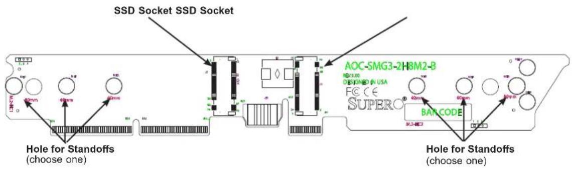
text_image
SSD Socket SSD Socket Hole for Standoffs (choose one) AOC-SMG3-2H8M2-B DESIGNED IN USA FCCC SUPERO® BAN CODE Hole for Standoffs (choose one)Figure 3-8. M.2 SSD Add-on Card (AOC-SMG3-2H8M2-B)
To Install M.2 SSDs and the Carrier Card
Caution: Use industry-standard anti-static equipment, such as gloves or wrist strap, and follow precautions to avoid damage caused by ESD.
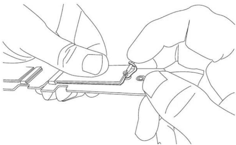
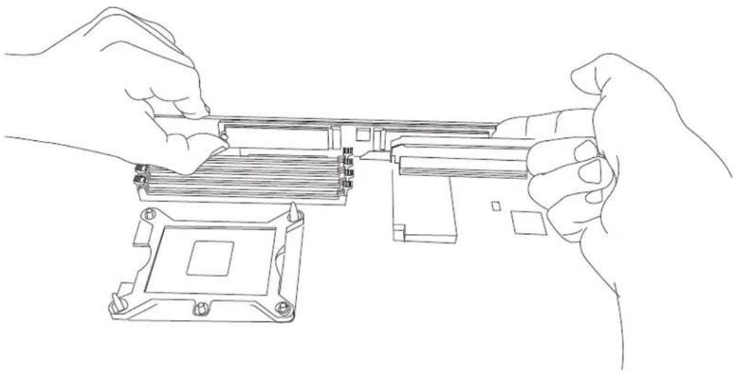
- For each SSD, install the standoff in the appropriate hole that corresponds with the form factor of the SSD to be installed (42mm, 60mm or 80mm length SSDs are supported). Push the plastic standoff until it snaps into the carrier card.

natural_image
Line drawing of two hands assembling a mechanical component (no text or symbols)Figure 3-9. Inserting the Standoff (drawing shows hole for 60 mm SSD)
- Insert the SSD into the socket on the expansion card. Then push it flat against the carrier card and the plastic standoff.
- Secure the SSD by firmly inserting the standoff plug.
natural_image
Line drawing of two hands assembling or adjusting a small electronic component (no text or symbols present)Figure 3-10. Inserting the Standoff Plug
text_image
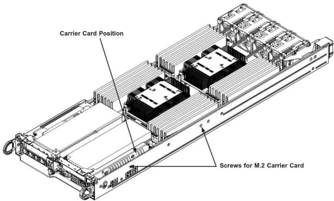
Carrier Card Position Screws for M.2 Carrier CardFigure 3-11. Locating the M.2 Carrier Card Slot and Screws
- Power down the node and remove it from the chassis.
-
On the motherboard, remove any DIMMs obstructing access to the carrier card slot.
-
Push the carrier card into the slot on the motherboard. With the screws provided, secure it to the side of the node chassis.
- Replace any DIMMs that may have been removed.
- Replace the node into the chassis, and power up the system.
Removing the M.2 Carrier Card
- Power down the node as described in Section 3.1 and remove it from the chassis.
- Remove any DIMMs obstructing access to the M.2 carrier card.
- Remove the two screws from the left side (viewed from the chassis front) of the node chassis that secure the M.2 carrier card to the node chassis. (Figure 3-11)
natural_image
Line drawing of hands assembling a CPU socket (no text or symbols present)Figure 3-12. Removing the Carrier Card
- Pull the card out of the socket by both notched edges (front and back) of the card. Be careful not to exert any force on any M.2 SSDs already installed on the card.
- If you want to remove an installed SSD, remove the plug from the standoff and allow the M.2 SSD to lift up at an angle before removing it from the M.2 socket.
Installing Expansion Cards
The system can accommodate two low-profile PCI-E 3.0 x16 cards per node, for a total of eight in the chassis.
Installing an Expansion Card
-
Power down the node and remove it from the chassis.
-
Remove the screws holding the riser card brackets.
- For the right side (looking from the node rear), remove the three screws on the right. - For the left side, remove the three screws on the left.
-
Remove the blank PCI shield from the bracket.
-
Slide the expansion card bracket into the open PCI slot while plugging the expansion card into the riser card.
-
Secure the expansion card bracket into the PCI slot with a screw.
-
Replace the riser card brackets and secure with the screws.

text_image
Riser Card Bracket screw Riser Card Bracket screw Riser Card Bracket screw Riser Card Bracket screwFigure 3-13. Installing the Expansion Card
SIOM Card
The Supermicro Input/Output module (SIOM) card provides options for network connection. It is inserted into a SIOM slot on the motherboard. This installation is usually performed by a system integrator or manufacturer.
Installing the SIOM Card
Before installing the motherboard into the node drawer:
- Power down the node and remove it from the chassis.
- Insert the SIOM card into the motherboard as shown.
- Secure it with a screw. Note: Torque range is 0.20-0.28 Nm.
- Install the covering bracket on the rear of the node drawer.
- Install the motherboard including the other screw on the SIOM card.
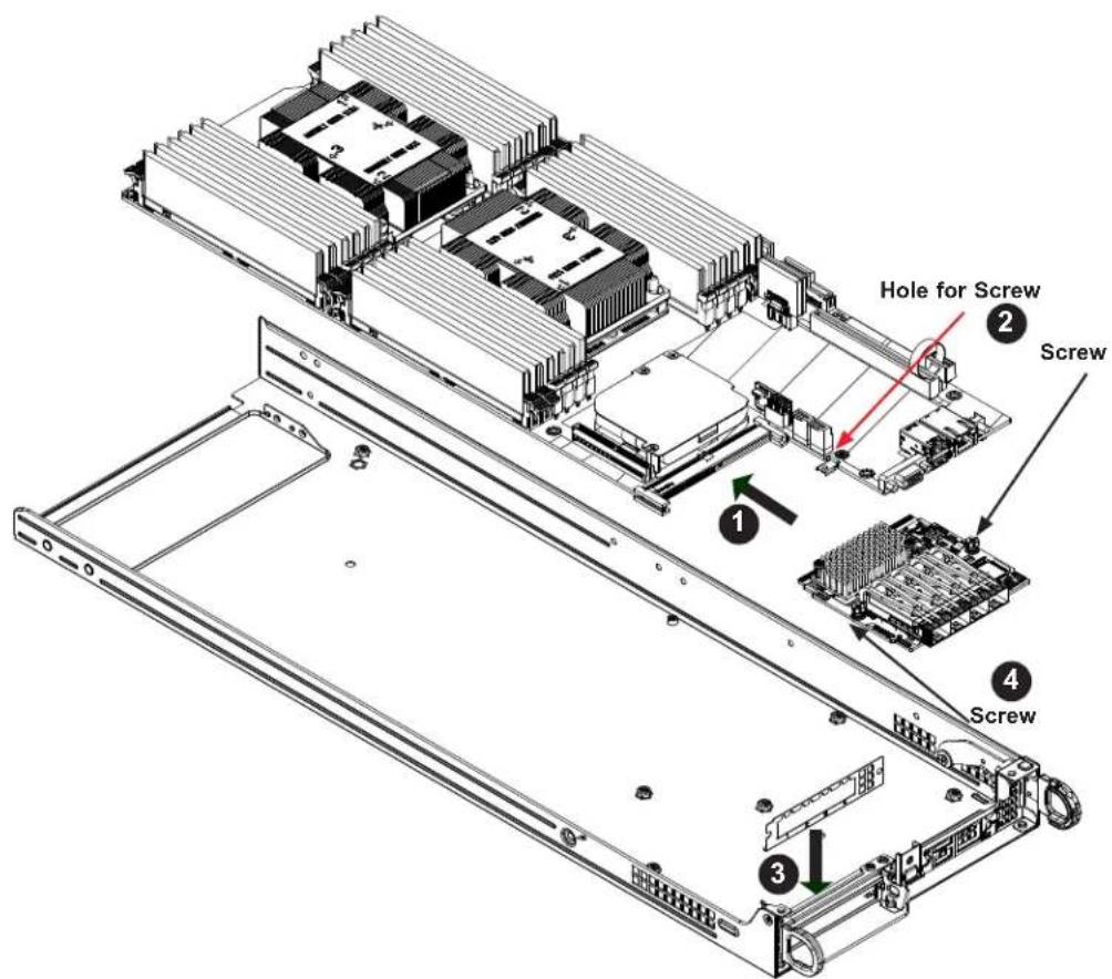
text_image
Hole for Screw Screw 1 2 3 4 ScrewFigure 3-14. SIOM Card Position on Node Drawer Rear
System Fans
Four fans provide cooling. They can be replaced without powering down the entire system. Fan speed is controlled by a system temperature setting in IPMI. If a fan fails, the remaining fans will ramp up to full speed. The system can continue to run with a failed fan. Replace any failed fan at your earliest convenience with the same type and model.

natural_image
Technical line drawing of an internal server rack with multiple drive bays and ventilation ducts (no text or symbols)Figure 3-15. System Fan Placement
Changing a System Fan
- Determine which fan is failing. Fan status can be found in the IPMI sensor log.
- Power down the associated node as described in Section 3.1.
- Remove the node drawer from the chassis.
- Remove all the fan power cables from the motherboard connections.
- Lift the fan housing up and out of the node.
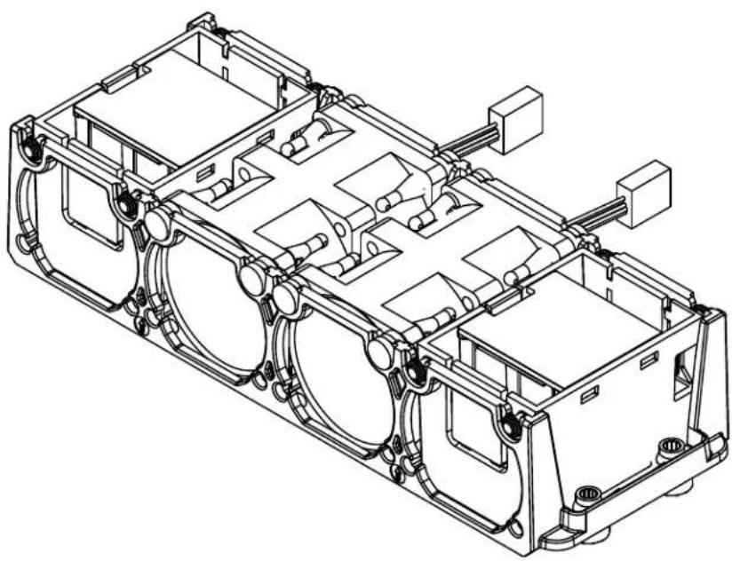
natural_image
Technical line drawing of an internal combustion engine housing assembly (no text or labels)Figure 3-16. Fans in Housing
- Push the fan up from the bottom and out of the top of the housing.
- Place the replacement fan into the vacant space in the housing while making sure the arrows on the top of the fan (indicating air direction) point in the same direction as the arrows on the other fans.
- Put the fan housing back into the node and reconnect the cables.
- Replace the node and confirm that the fan is working properly before replacing the chassis cover.
Installing the Air Shrouds
Air shrouds concentrate airflow to maximize fan efficiency. The system requires air shrouds for each motherboard node.
Installing an Air Shroud
The motherboard, any expansion cards, and all components must be installed in the node tray. Place the air shrouds as shown below. Secure with screws as needed.
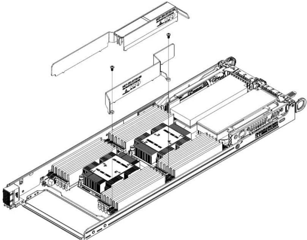
natural_image
Technical line drawing of an electronic device chassis showing internal components and mounting hardware (no text or symbols)Figure 3-17. Installing an Air Shroud
Checking the Server Air Flow
- Make sure there are no objects to obstruct airflow in and out of the server.
- Do not operate the server without drives or drive carriers in the drive bays.
- Use only recommended server parts.
- Make sure no wires or foreign objects obstruct air flow through the chassis. Pull all excess cabling out of the airflow path or use shorter cables.
The control panel LEDs display system heat status. See “Control Panel” in Chapter 1 for details.
Overheating
There are several possible responses if the system overheats.
- Use the LEDs to determine the nature of the overheating condition.
- Confirm that the chassis covers are installed properly.
- Make sure all fans are present and operating normally.
- Check the routing of the cables.
- Verify that the heatsinks are installed properly.
Power Supply
The chassis features redundant power supplies. The power modules can be changed without powering down the system. New units can be ordered directly from Supermicro or authorized distributors.
These power supplies are auto-switching capable. This feature enables them to automatically sense the input voltage and operate at a 100-120v or 180-240v. An amber light will be illuminated on the power supply when the power is off. An illuminated green light indicates that the power supply is operating.
Note: PWS-2K60A-1R power supplies use an IEC320 C20 AC input connector
Replacing the Power Supply
- Unplug the AC cord from the module to be replaced.
- Push the release tab on the back of the power supply as illustrated.

text_image
3 2 Release TabFigure 3-18. Power Supply Release Tab
- Pull the power supply out using the handle provided.
- Replace the failed power module with the same model.
- Push the new power supply module into the power bay until it clicks.
- Plug the AC power cord back into the module.
Chapter 4
Motherboard Connections
This section describes the connections on the motherboard and provides pinout definitions.
Note that depending on how the system is configured, not all connections are required.
The LEDs on the motherboard are also described here. A motherboard layout indicating component locations may be found in Chapter 1.
Please review the Safety Precautions in Appendix B before installing or removing components.
4.1 Power Connections
Power to the nodes is provided through the backplane.
4.2 Headers and Connectors
Fan Headers
There are four fan headers on the motherboard (FANA-FAND). These are 4-pin fan headers; pins 1-3 are backward compatible with traditional 3-pin fans. The onboard fan speeds are controlled by Thermal Management in IPMI. When using Thermal Management setting, please use all 3-pin fans or all 4-pin fans.
| Fan HeaderPin Definitions |
| Pin# Definition |
| 1 Ground (Black) |
| 2 +12V (Red) |
| 3 Tachometer |
| 4 PWM Control |
TPM Header
The JTPM1 header is used to connect a Trusted Platform Module (TPM), which is available from Supermicro. A TPM is a security device that supports encryption and authentication in hard drives. It enables the motherboard to deny access if the TPM associated with the hard drive is not installed in the system. More information at http://www.supermicro.com/manuals/other/TPM.pdf.
| Trusted Platform Module/Port 80 Header Pin Definitions | ||
| Pin# Definition Pin# Definition | ||
| 1 +3.3V 2 SPI_CS# | ||
| 3 RESET# 4 SPI_MISO | ||
| 5 SPI_CLK 6 GND | ||
| 7 SPI_MOSI 8 | ||
| 9 +3.3V Stdby 10 SPI_IRQ# | ||
RAID Key Header
A RAID Key header is located at JRK1 on the motherboard. It supports VMD used in creating optional advanced NVMe RAID configurations.
| Intel RAID KeyPin Definitions | |
| Pins Definition | |
| 1 GND | |
| 2 PU 3.3V Stdby | |
| 3 GND | |
| 4 PCH RAID KEY | |
Powered SATADOM (SuperDOM)
A SATADOM (Device-on-Disk) is located at I-SATA6 on the motherboard. I-SATA6 is used with a Supermicro SuperDOM, which is a yellow SATADOM connector with a power pin built in, and no external power supply is needed. Supermicro SuperDOM is backward-compatible with a regular SATA HDD or SATADOM that requires an external power supply.
Control Panel
JF1 contains header pins for various control panel connections. See the figure below for the pin locations and definitions of the control panel buttons and LED indicators.
All JF1 wires have been bundled into a single cable to simplify this connection. Make sure the red wire plugs into pin 1 as marked on the motherboard. The other end connects to the control panel PCB board.
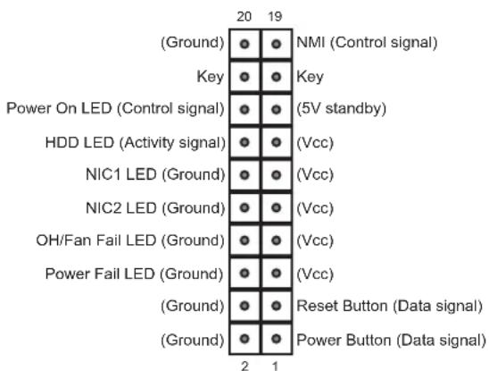
text_image
(Ground) Key Power On LED (Control signal) HDD LED (Activity signal) NIC1 LED (Ground) NIC2 LED (Ground) OH/Fan Fail LED (Ground) Power Fail LED (Ground) Reset Button (Data signal) Power Button (Data signal)Figure 4-1. JF1: Control Panel Pins
Power Button
The Power Button connection is located on pins 1 and 2 of JF1. Momentarily contacting both pins will power on/off the system. This button can also be configured to function as a suspend button (with a setting in the BIOS - see Chapter 6). To turn off the power when the system is in suspend mode, press the button for 4 seconds or longer.
| Power ButtonPin Definitions (JF1) | |
| Pin# Definition | |
| 1 Signal | |
| 2 Ground | |
Reset Button
The Reset Button connection is located on pins 3 and 4 of JF1. Attach it to a hardware reset switch on the computer case.
| Reset ButtonPin Definitions (JF1) |
| Pin# Definition |
| 3 Reset |
| 4 Ground |
Power Fail LED
The Power Fail LED connection is located on pins 5 and 6 of JF1.
| Power Fail LEDPin Definitions (JF1) | |
| Pin# Definition | |
| 5 3.3V | |
| 6 PWR Supply Fail | |
Overheat (OH)/Fan Fail
Connect an LED cable to pins 7 and 8 of JF1 to use the Overheat/Fan Fail LED connections. The LED on pin 8 provides warnings of overheat or fan failure.
| OH/Fan Fail Indicator Status | |
| Status Definition | |
| Off Normal | |
| On Overheat | |
| Flashing Fan Fail |
| OH/Fan Fail LEDPin Definitions (JF1) | |
| Pin# Definition | |
| 7 Blue | LED |
| 8 OH/Fan Fail LED | |
The NIC (Network Interface Controller) LED connection for LAN port 1 is located on pins 11 and 12 of JF1, and the LED connection for LAN Port 2 is on pins 9 and 10. Attach the NIC LED cables here to display network activity.
| LAN1/LAN2 LEDPin Definitions (JF1) | |
| Pin# | Definition |
| 9 | NIC2 Activity LED |
| 10 | NIC2 Link LED |
| 11 | NIC1 Activity LED |
| 12 | NIC1 Link LED |
HDD LED/UID Switch
The HDD LED/UID Switch connection is located on pins 13 and 14 of JF1. Attach a cable to pin 14 to show hard drive activity status. Attach a cable to pin 13 to use UID switch. Refer to the table below for pin definitions.
| HDD LEDPin Definitions (JF1) |
| Pin# Definition |
| 13 3.3V Standby/UID Switch |
| 14 HDD Active |
Power LED
The Power LED connection is located on pins 15 and 16 of JF1.
| Power LEDPin Definitions (JF1) |
| Pin# Definition |
| 15 3.3V |
| 16 Power LED |
NMI Button
The non-maskable interrupt button header is located on pins 19 and 20 of JF1.
| NMI ButtonPin Definitions (JF1) |
| Pin# Definition |
| 19 Control |
| 20 Ground |
4.3 Ports
Input/Output Rear Panel
Each node provides the following input/output ports.

text_image
Diagram showing five labeled components of an electronic device, including a VGA, Ethernet ports, and a connector.Figure 4-2. I/O Panel
| Rear Panel I/O Ports | |||
| No. | Description No. | Description | |
| 1. VGA Port 4. Dedicated IPMI LAN | |||
| 2. USB1 (3.0) 5. Unit Identifier Switch | |||
| 3. USB0 (3.0) | |||
LAN Ports
Network ports are provided by a SIOM card. Several models are available.
There is also a dedicated IPMI LAN port on the I/O back panel.
4.4 Jumpers
Explanation of Jumpers
To modify the operation of the motherboard, jumpers are used to choose between optional settings. Jumpers create shorts between two pins to change the function associated with it. Pin 1 is identified with a square solder pad on the printed circuit board. See the motherboard layout page for jumper locations.
Note: On a two-pin jumper, "Closed" means the jumper is on both pins and "Open" indicates the jumper is either on only one pin or has been completely removed.
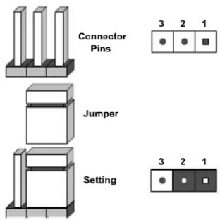
text_image
Connector Pins Jumper Setting 3 2 1 3 2 1CMOS Clear
JBT1 is used to clear CMOS, which will also clear any passwords. Instead of pins, this jumper consists of contact pads to prevent accidentally clearing the contents of CMOS.
To Clear CMOS
- First power down the system and unplug the power cord(s).
- Remove the cover of the chassis to access the motherboard.
- Remove the onboard battery from the motherboard.
- Short the CMOS pads with a metal object such as a small screwdriver for at least four seconds.
- Remove the screwdriver (or shorting device).
- Replace the cover, reconnect the power cord(s) and power on the system.
Notes: Clearing CMOS will also clear all passwords.
Do not use the PW_ON connector to clear CMOS.

JBT1 contact pads
4.5 LED Indicators
IPMI LAN LEDs
A dedicated IPMI LAN port is also included on the motherboard. The amber LED on the right of the IPMI LAN port indicates activity, while the LED on the left indicates the speed of the connection.
IPMI LAN

Activity LEDLink LED
| IPIMI LAN LED(Connection Speed Indicator) | |
| LED Color Definition | |
| Off No connection | |
| Green 100 Mb/s | |
| Amber 1 Gb/s |
BMC Heartbeat LED
BMC_HB_LED1 is the BMC heartbeat LED. When the LED is blinking green, BMC is functioning normally.
4.6 PCIe 3.0 Slots
- Two x16 slots on the motherboard. SXB3 is supported by CPU1 and SXB42 is supported by CPU2.
- One x4 slot supported by CPU1, located at SXB1. SXB1 is used for I-SATA0\~5 and S-SATA0\~5.
• One x24 slot supported by CPU2 is located at SXB2.
Super IO Module (SIOM) Networking Slot
There is one SIOM networking slot (PCI-E 3.0 x16).
4.7 SATA Ports
I-SATA 3.0 and S-SATA 3.0 Ports
The X11DPT-BHX11DPT-BH has eight SATA 3.0 ports (I-SATA0-5/S-SATA0-5/I-SATA6 + 1 SATA DOM). These are supported by the Intel C621 chipset. I-SATA0-5 and S-SATA0-5 are located at SXB1 and are supported by CPU1.
Chapter 5
Software
After the hardware has been installed, you can install the Operating System (OS), configure RAID settings and install the drivers.
5.1 Microsoft Windows OS Installation
If you will be using RAID, you must configure RAID settings before installing the Windows OS and the RAID driver. Refer to the RAID Configuration User Guides posted on our website at www.supermicro.com/support/manuals.
Installing the OS
- Create a method to access the MS Windows installation ISO file. That might be a DVD, perhaps using an external USB/SATA DVD drive, or a USB flash drive, or the IPMI KVM console.
- Retrieve the proper RST/RSTe driver. Go to the Supermicro web page for your motherboard and click on "Download the Latest Drivers and Utilities", select the proper driver, and copy it to a USB flash drive.
- Boot from a bootable device with Windows OS installation. You can see a bootable device list by pressing F11 during the system startup.

text_image
Please select boot device: ATEN Virtual CDROM YSOJ → IPMI virtual drive (Legacy) ASUS SDRW-08D2S-U F601 → USB DVD device (Legacy) USB FLASH DRIVE PMAP → USB flash drive with OS installation (Legacy) IBA 40-10G Slot 1900 v1060 → PXE boot (Legacy) UEFI: ATEN Virtual CDROM YSOJ → IPMI virtual drive (UEFI) UEFI: ASUS SDRW-08D2S-U F601 → USB DVD device (UEFI) UEFI: Built-in EFI Shell Enter Setup ↑ and ↓ to move selection ENTER to select boot device ESC to boot using defaultsFigure 5-1. Select Boot Device
- During Windows Setup, continue to the dialog where you select the drives on which to install Windows. If the disk you want to use is not listed, click on "Load driver" link at the bottom left corner.
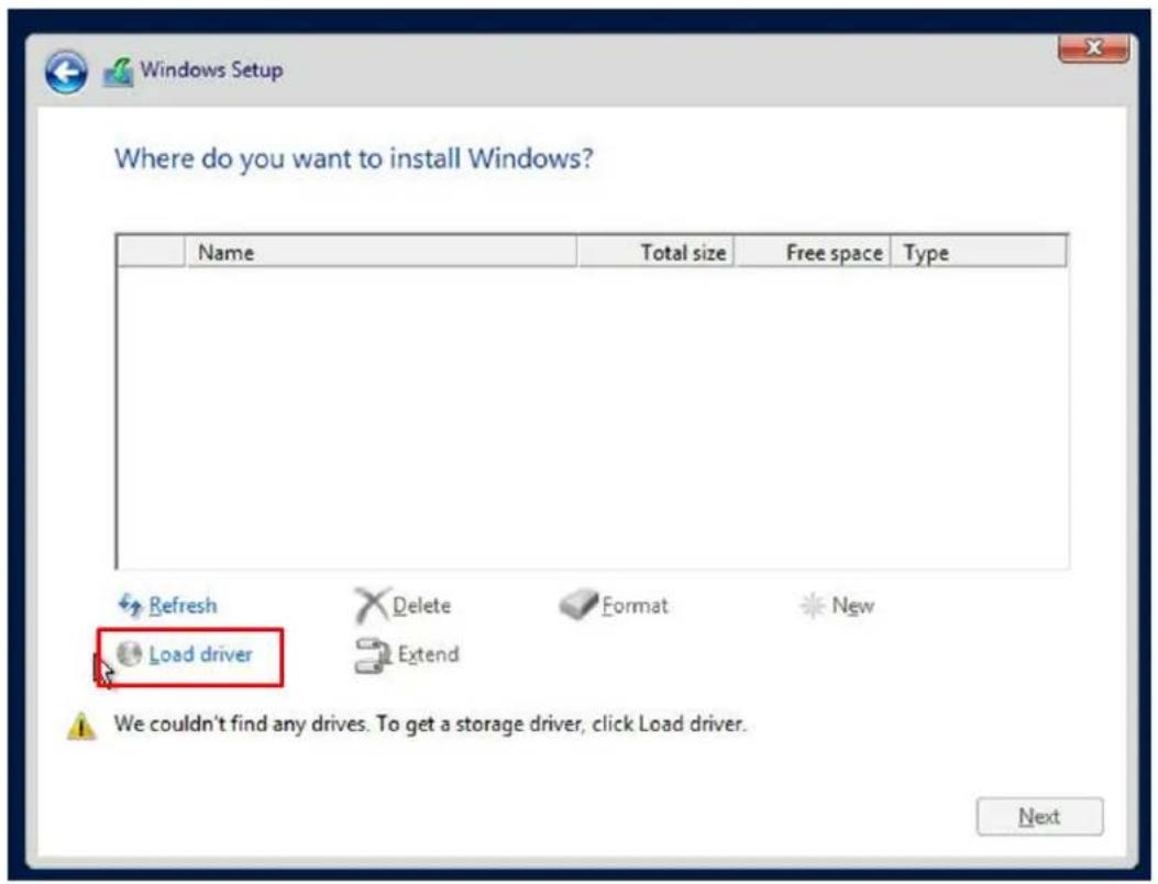
text_image
Where do you want to install Windows? Name Total size Free space Type Refresh Delete Format New Load driver Extend We couldn't find any drives. To get a storage driver, click Load driver. NextFigure 5-2. Load Driver Link
To load the driver, browse the USB flash drive for the proper driver files.
- For RAID, choose the SATA/sSATA RAID driver indicated then choose the storage drive on which you want to install it.
-
For non-RAID, choose the SATA/sSATA AHCI driver indicated then choose the storage drive on which you want to install it.
-
Once all devices are specified, continue with the installation.
- After the Windows OS installation has completed, the system will automatically reboot multiple times.
5.2 Driver Installation
The Supermicro website contains drivers and utilities for your system at https://www.supermicro.com/wdl/driver. Some of these must be installed, such as the chipset driver.
After accessing the website, go into the CDR_Images (in the parent directory of the above link) and locate the ISO file for your motherboard. Download this file to a USB flash drive or a DVD. (You may also use a utility to extract the ISO file if preferred.)
Another option is to go to the Supermicro website at http://www.supermicro.com/products/. Find the product page for your motherboard, and "Download the Latest Drivers and Utilities". Insert the flash drive or disk and the screenshot shown below should appear.
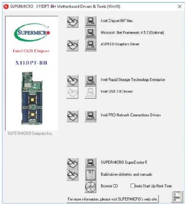
text_image
SUPERMICRO X11DPT-BH Motherboard Drivers & Tools (Win10) SUPERMICRO Intel C621 Chipset X11DPT-BH SUPERMICRO Computer Inc. Intel Chipset INF files Microsoft .Net Framework 4.5.2 (Optional) ASPEED Graphics Driver Intel Rapid Storage Technology Enterprise Intel USB 3.0 Drivers Intel PRO Network Connections Drivers SUPERMICRO SuperDoctor 5 Build driver disketes and manuals Browse CC Auto Start Up Next Time For more information, please visit SUPERMICRO's website.Figure 5-3. Driver & Tool Installation Screen
Note: Click the icons showing a hand writing on paper to view the readme files for each item. Click the computer icons to the right of these items to install each item (from top to the bottom) one at a time. After installing each item, you must re-boot the system before moving on to the next item on the list. The bottom icon with a CD on it allows you to view the entire contents.
5.3 SuperDoctor® 5
The Supermicro SuperDoctor 5 is a program that functions in a command-line or web-based interface for Windows and Linux operating systems. The program monitors such system health information as CPU temperature, system voltages, system power consumption, fan speed, and provides alerts via email or Simple Network Management Protocol (SNMP).
SuperDoctor 5 comes in local and remote management versions and can be used with Nagios to maximize your system monitoring needs. With SuperDoctor 5 Management Server (SSM Server), you can remotely control power on/off and reset chassis intrusion for multiple systems with SuperDoctor 5 or IPMI. SuperDoctor 5 Management Server monitors HTTP, FTP, and SMTP services to optimize the efficiency of your operation.

text_image
SuperDoctor 5 Home info: www.humanlab.com Certificate error: localhost:1044/superdoctor SuperDoctor 5 Select Language: English (ADMIN) Language Motherboard: C78366-CB-ML Voltage 0.0V 12.0V 14.0V 16.0V 18.0V 20.0V 22.0V 24.0V 26.0V 28.0V 30.0V 32.0V 34.0V 36.0V 38.0V 40.0V 42.0V 44.0V 46.0V 48.0V 50.0V 52.0V 54.0V 56.0V 58.0V 60.0V 62.0V 64.0V 66.0V 68.0V 70.0V 72.0V 74.0V 76.0V 78.0V 80.0V 82.0V 84.0V 86.0V 88.0V 90.0V 92.0V 94.0V 96.0V 98.0V 100.0V 102.0V 104.0V 106.0V 108.0V 110.0V 112.0V 114.0V 116.0V 118.0V 120.0V 122.0V 124.0V 126.0V 128.0V 130.0V 132.0V 134.0V 136.0V 138.0V 140.0V 142.0V 144.0V 146.0V 148.0V 150.0V 152.0V 154.0V 156.0V 158.0V 160.0V 162.0V 164.0V 166.0V 168.0V 170.0V 172.0V 174.0V 176.0V 178.0V 180.0V 182.0V 184.0V 186.0V 188.0V 190.0V 192.0V 194.0V 196.0V 198.0V 200.0V 202.0V 204.0V 206.0V 208.0V 210.0V 212.0V 214.0V 216.0V 218.0V 220.0V 222.0V 224.0V 226.0V 228.0V 230.0V 232.0V 234.0V 236.0V 238.0V 240.0VFigure 5-4. SuperDoctor 5 Interface Display Screen (Health Information)
.4 BMC
The motherboard provides remote access, monitoring and management through the baseboard management controller (BMC) and other management controllers distributed among different system modules. There are several BIOS settings that are related to BMC. For general documentation and information on BMC, visit our website at:
www.supermicro.com/en/solutions/management-software/bmc-resources
BMC ADMIN User Password
For security, each system is assigned a unique default BMC password for the ADMIN user. This can be found on a sticker on the chassis and a sticker on the motherboard. The sticker also displays the BMC MAC address. If necessary, the password can be reset using the Supermicro IPMICFG tool.

text_image
BMC AC1F6BC PWD SUOKJFigure 5-5. BMC Password Label
Chapter 6
BIOS
6.1 Introduction
This chapter describes the AMI BIOS setup utility for the X11DPT-BH and provides the instructions on navigating the setup screens. The BIOS is stored in a Flash EEPROM and can be updated.
Note: Due to periodic changes to the BIOS, some settings may have been added or deleted since this manual was published.
Starting BIOS Setup Utility
To enter the AMI BIOS setup utility screens, press the
The BIOS screens have three main frames. The large left frame displays options can be configured by the user. These are blue. When an option is selected, it is highlighted in white. Settings printed in Bold are the default values.
In the left frame, a "▶" indicates a submenu. Highlighting such an item and pressing the
The upper right frame displays helpful information for the user. The AMI BIOS has default informational messages built in. The manufacturer retains the option to include, omit, or change any of these informational messages.
The lower right frame lists navigational methods. The AMI BIOS setup utility uses a key-based navigation system called hot keys. Most of these hot keys can be used at any time during setup navigation. These keys include
Some system parameters may be changed.
6.2 Main Setup
When running the AMI BIOS setup utility, it starts with the Main screen. You can always return to it by selecting the Main tab on the top of the screen.
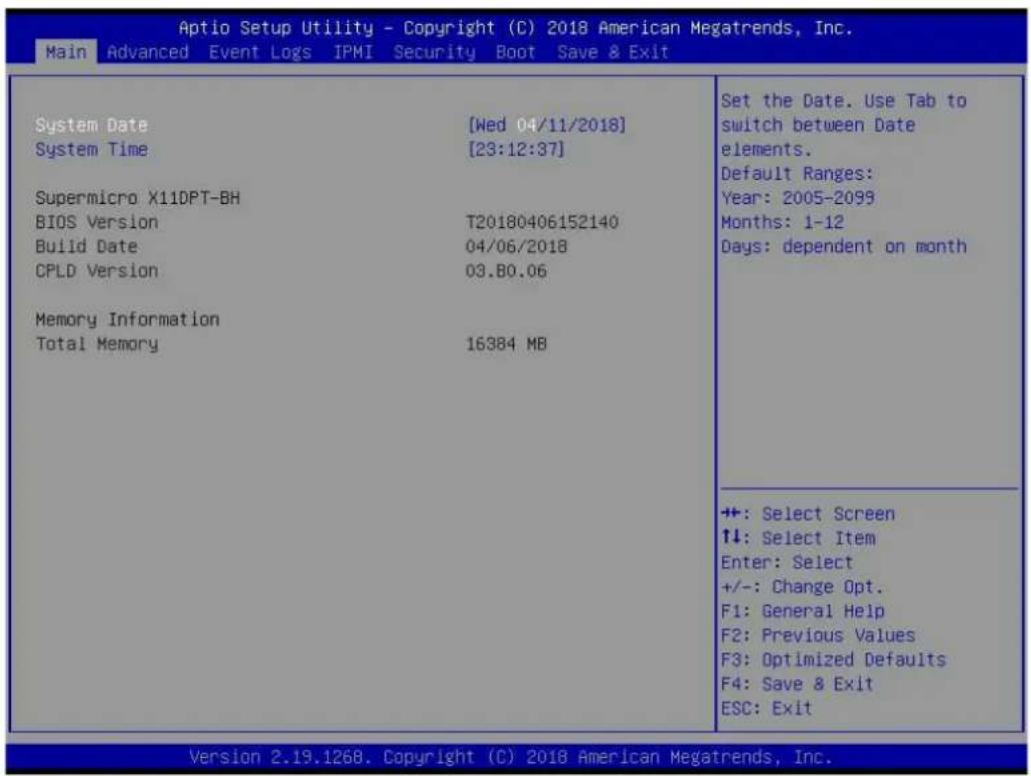
text_image
Aptio Setup Utility - Copyright (C) 2018 American Megatrends, Inc. Main Advanced Event Logs IPMI Security Boot Save & Exit System Date [Wed 04/11/2018] System Time [23:12:37] Supermicro X11DPT-BH BIOS Version T20180406152140 Build Date 04/06/2018 CPLD Version 03.80.06 Memory Information Total Memory 16384 MB Set the Date. Use Tab to switch between Date elements. Default Ranges: Year: 2005-2099 Months: 1-12 Days: dependent on month +: Select Screen ↑↓: Select Item Enter: Select +/-: Change Opt. F1: General Help F2: Previous Values F3: Optimized Defaults F4: Save & Exit ESC: Exit Version 2.19.1268. Copyright (C) 2018 American Megatrends, Inc.The Main tab page allows you to set the date and time, and it displays system information.
System Date/System Time
Use this option to change the system date and time. Highlight System Date or System Time using the arrow keys. Enter new values using the keyboard. Press the
Note: The time is in the 24-hour format. For example, 5:30 P.M. appears as 17:30:00. The date's default value is 01/01/2016 after RTC reset.
Supermicro X11DPT-BH (Motherboard model)
BIOS Version
Build Date (of the BIOS)
CPLD (Complex Programmable Logic Device) Version: This item displays the CPLD version used in the system.
Memory Information
Total Memory (for the system)
Memory Speed
6.3 Advanced Setup Configurations
Use the arrow keys to select the Advanced tab and press
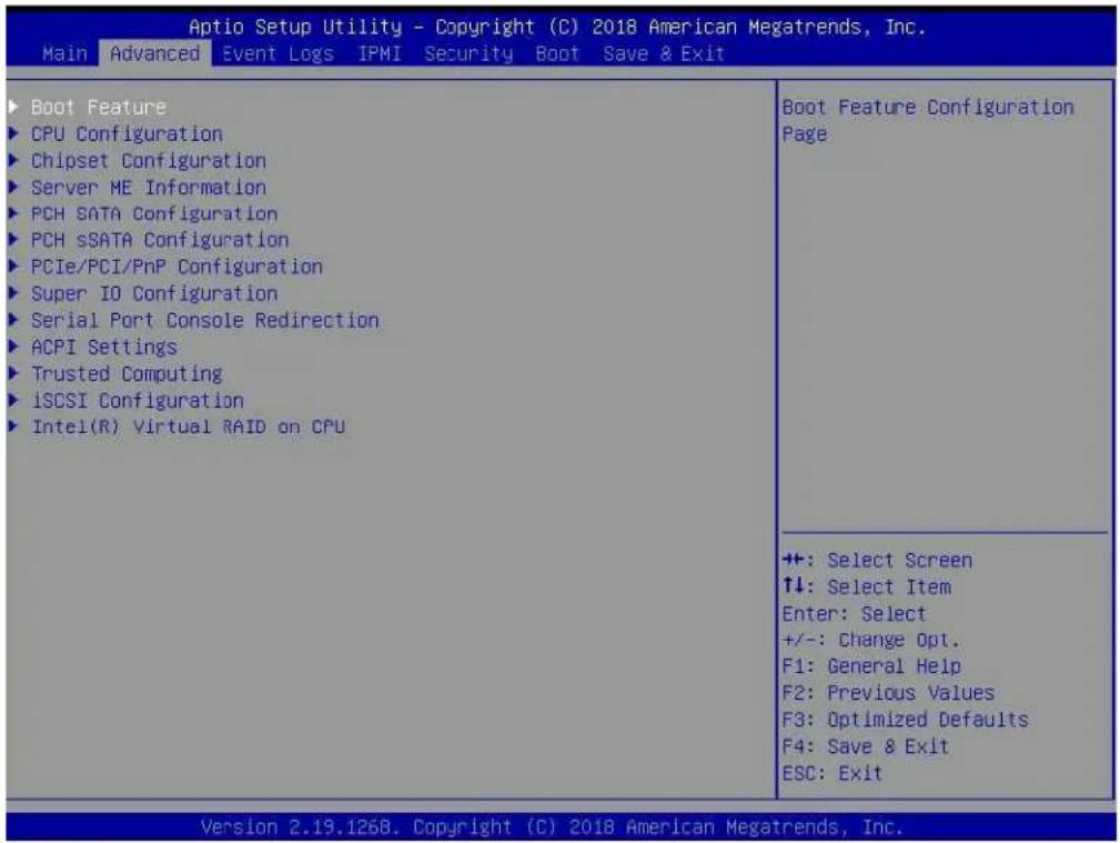
text_image
Aptio Setup Utility - Copyright (C) 2018 American Megatrends, Inc. Main Advanced Event Logs IPMI Security Boot Save & Exit ▶ Boot Feature ▶ CPU Configuration ▶ Chipset Configuration ▶ Server ME Information ▶ PCH SATA Configuration ▶ PCH SSATA Configuration ▶ PCIe/PCI/PnP Configuration ▶ Super IO Configuration ▶ Serial Port Console Redirection ▶ ACPI Settings ▶ Trusted Computing ▶ iSDSI Configuration ▶ Intel(R) Virtual RAID on CPU Boot Feature Configuration Page ++: Select Screen ↑↓: Select Item Enter: Select +/-: Change Opt. F1: General Help F2: Previous Values F3: Optimized Defaults F4: Save & Exit ESC: Exit Version 2.19.1268. Copyright (C) 2018 American Megatrends, Inc.Caution: Take caution when changing the Advanced settings. An incorrect value, a very high DRAM frequency, or an incorrect DRAM timing setting may make the system unstable. If this occurs, revert to the manufacture default settings.
▶Boot Feature
Quiet Boot
Use this feature to select the screen display between the POST messages and the OEM logo upon bootup. Select Disabled to display the POST messages. Select Enabled to display the OEM logo instead of the normal POST messages. The options are Disabled and Enabled.
Option ROM Messages
Use this feature to set the display mode for the Option ROM. Select Keep Current to display the current AddOn ROM setting. Select Force BIOS to use the Option ROM display set by the system BIOS. The options are Force BIOS and Keep Current.
Bootup NumLock State
Use this feature to set the Power-on state for the
Wait For "F1" If Error
Use this feature to force the system to wait until the 'F1' key is pressed if an error occurs. The options are Disabled and Enabled.
INT19 (Interrupt 19) Trap Response
Interrupt 19 is the software interrupt that handles the boot disk function. When this item is set to Immediate, the ROM BIOS of the host adaptors will "capture" Interrupt 19 at bootup immediately and allow the drives that are attached to these host adaptors to function as bootable disks. If this item is set to Postponed, the ROM BIOS of the host adaptors will not capture Interrupt 19 immediately and allow the drives attached to these adaptors to function as bootable devices at bootup. The options are Immediate and Postponed.
Re-try Boot
If this item is enabled, the BIOS will automatically reboot the system from a specified boot device after its initial boot failure. The options are Disabled, Legacy Boot, and EFI Boot.
Install Windows 7 USB support
Enable this feature to use the USB keyboard and mouse during the Windows 7 installation, since the native XHCI driver support is unavailable. Use a SATA optical drive as a USB drive, and USB CD/DVD drives are not supported. Disable this feature after the XHCI driver has been installed in Windows. The options are Disabled and Enabled.
Port 61h Bit-4 Emulation
Select Enabled to enable the emulation of Port 61h but-4 toggling in SMM (System Management Mode). The options are Disabled and Enabled.
▶Power Configuration
Watch Dog Function
If enabled, the Watch Dog Timer will allow the system to reset or generate NMI based on jumper settings when it is expired for more than five minutes. The options are Disabled and Enabled.
Restore on AC Power Loss
Use this feature to set the power state after a power outage. Select Stay Off for the system power to remain off after a power loss. Select Power On for the system power to be turned on after a power loss. Select Last State to allow the system to resume its last power state before a power loss. The options are Stay Off, Power On, and Last State.
Power Button Function
This feature controls how the system shuts down when the power button is pressed. Select 4 Seconds Override for the user to power off the system after pressing and holding the power
button for 4 seconds or longer. Select Instant Off to instantly power off the system as soon as the user presses the power button. The options are Instant Off and 4 Seconds Override.
Throttle on Power Fail
Use this feature to decrease system power by throttling CPU frequency when one power supply has failed. The options are Disabled and Enabled.
System Firmware Progress Log
▶CPU Configuration
Processor Configuration
The following CPU information will display:
- Processor BSP Revision
- Processor Socket
- Processor ID
- Processor Frequency
- Processor Max Ratio
- Processor Min Ratio
- Microcode Revision
- L1 Cache RAM
- L2 Cache RAM
- L3 Cache RAM
- Processor 0 Version
- Processor 1 Version
Hyper-Threading (ALL) (Available when supported by the CPU)
Select Enable to support Intel Hyper-threading Technology to enhance CPU performance. The options are Disable and Enable.
Execute Disable Bit (Available if supported by the OS & the CPU)
Select Enabled to enable the Execute-Disable Bit, which will allow the processor to designate areas in the system memory where an application code can execute and where it cannot, thus preventing a worm or a virus from flooding illegal codes to overwhelm the processor
or damage the system during an attack. The default is Enable. (Refer to the Intel® and Microsoft® websites for more information.)
Intel Virtualization Technology
Select Enable to use Intel Virtualization Technology which will allow the I/O device assignments to be directly reported to the VMM (Virtual Memory Management) through the DMAR ACPI tables. This feature offers fully protected I/O resource-sharing across Intel platforms, providing the user with greater reliability, security, and availability in networking and data-sharing. The settings are Enable and Disable.
PPIN Control
Select Unlock/Enable to use the Protected-Processor Inventory Number (PPIN) in the system. The options are Unlock/Disable and Unlock/Enable
Hardware Prefetcher (Available when supported by the CPU)
If set to Enabled, the hardware prefetcher will prefetch streams of data and instructions from the main memory to the L2 cache to improve CPU performance. The options are Disable and Enable.
Adjacent Cache Prefetch (Available when supported by the CPU)
The CPU prefetches the cache line for 64 bytes if this feature is set to Disabled. The CPU prefetches both cache lines for 128 bytes as comprised if this feature is set to Enable.
DCU Streamer Prefetcher (Available when supported by the CPU)
Select Enabled to enable the DCU (Data Cache Unit) Streamer Prefetcher which will stream and prefetch data and send it to the Level 1 data cache to improve data processing and system performance. The options are Disable and Enable.
DCU IP Prefetcher (Available when supported by the CPU)
Select Enabled for DCU (Data Cache Unit) IP Prefetcher support, which will prefetch IP addresses to improve network connectivity and system performance. The options are Enable and Disable.
LLC Prefetch
If set to Enabled, the hardware prefetcher will prefetch streams of data and instructions from the main memory to the L3 cache to improve CPU performance. The options are Disable and Enable.
Extended APIC
Select Enable to activate APIC (Advanced Programmable Interrupt Controller) support. The options are Disable and Enable.
AES-NI
Select Enable to use the Intel Advanced Encryption Standard (AES) New Instructions (NI) to ensure data security. The options are Disable and Enable.
▶Advanced Power Management Configuration
Power Technology
This feature allows for switching between stored CPU Power Management profiles. The options are Disable, Energy Efficient and Custom.
Power Performance Tuning (Available when "Power Technology" is set to Custom
Select BIOS to allow the system BIOS to configure the Power-Performance Tuning Bias setting below. The options are BIOS Controls EPB and OS Controls EPB.
ENERGY\_PERF\_BIAS\_CFG Mode Energy (ENERGY PERFORMANCE BIAS CONFIGURATION Mode) (Available when supported by the Processor and when "Power Performance Tuning" is set to BIOS Controls EPB)
This feature allows the user to set the desired processor power use policy for the machine by prioritizing system performance or energy savings. Selecting Maximum Performance will maximize performance (to its highest potential); however, this may result in maximum power consumption. The higher the performance is, the higher the power consumption will be. Select Max Power Efficient to prioritize power saving; however, system performance may be substantially impacted. The options are Maximum Performance, Performance, Balanced Performance, Balanced Power, Power, and Max Power Efficient.
▶CPU P State Control
This feature allows the user to configure the following CPU power settings
Speedstep (Pstates)
Intel SpeedStep Technology allows the system to automatically adjust processor voltage and core frequency to reduce power consumption and heat dissipation. The options are Disabled and Enabled.
EIST PSD Funtion
This feature allows the user to choose between Hardware and Software to control the processor's frequency and performance (P-state). In HW_ALL mode, the processor hardware is responsible for coordinating the P-state, and the OS is responsible for keeping the P-state request up to date on all logical processors. In SW_ALL mode, the OS Power Manager is responsible for coordinating the P-state, and must initiate the transition on all Logical Processors. In SW_ANY mode, the OS Power Manager is responsible for coordinating the P-state and may initiate the transition on any Logical Processors. Options available: HW_ALL/SW_ALL/SW_ANY. Default setting is HW_ALL.
Turbo Mode
This feature will enable dynamic control of the processor, allowing it to run above stock frequency. The options are Disable and Enable.
▶Hardware PM State Control
Hardware P-States
If this feature is set to Disable, hardware will choose a P-state setting for the system based on an OS request. If this feature is set to Native Mode, hardware will choose a P-state setting based on OS guidance. If this feature is set to Native Mode with No Legacy Support, hardware will choose a P-state setting independently without OS guidance. The options are Disable, Native Mode, Out of Band Mode, and Native Mode with No Legacy Support.
▶CPU C State Control
Autonomous Core C-State
Select Enable to support Autonomous Core C-State control which will allow the processor core to control its C-State setting automatically and independently. The options are Enable and Disable.
CPU C6 Report
Select Enabled to allow the BIOS to report the CPU C6 State (ACPI C3) to the operating system. During the CPU C6 State, the power to all cache is turned off. The options are Disable, Enable, and Auto.
Enhanced Halt State (C1E)
Select Enabled to use Enhanced Halt-State technology, which will significantly reduce the CPU's power consumption by reducing the CPU's clock cycle and voltage during a Halt-state. The options are Disable and Enable.
▶Package C State Control
Package C State
This feature allows the user to set the limit on the C State package register. The options are C0/C1 State, C2 State, C6 (Non Retention) State, C6 (Retention) state, No Limit, and Auto..
▶CPU T State Control
Software Controlled T-States
Select Enable to support Software Controlled Throttling states for CPUs installed on the motherboard. Such throttling states control the running time of CPUs with the goal of cooling down CPUs and preventing them from burning out. The options are Disable and Enable.
▶Chipset Configuration
Warning: Setting the wrong values in the following features may cause the system to malfunction.
▶ North Bridge
This feature allows the user to configure the following North Bridge settings.
▶UPI Configuration
▶ UPI General Configuration
The following UPI information will display:
• Number of CPU
• Number of IIO
• Current UPI Link Speed
• Current UPI Link Frequency
• UPI Global MMIO Low Base / Limit
• UPI Global MMIO High Base / Limit
• UPI Pci-e Configuration Base / Size
Degrade Precedence
Use this feature to set degrade precedence when system settings are in conflict. Select Topology Precedence to degrade Features. Select Feature Precedence to degrade Topology. The options are Topology Precedence and Feature Precedence.
Link L0p Enable
Select Enable for Link L0p support. The options are Enable and Disable.
Link L1 Enable
Select Enable for Link L1 support. The options are Enable and Disable.
IO Directory Cache (IODC)
IO Directory Cache is an 8-entry cache that stores the directory state of remote IIO writes and memory lookups, and saves directory updates. Use this feature to lower cache to cache (C2C) transfer latencies. The options are Disable, Auto, Enable for Remote InvItoM Hybrid Push, InvItoM AllocFlow, Enable for Remote InvItoM Hybrid AllocNonAlloc, and Enable for Remote InvItoM and Remote WViLF.
SNC
Sub NUMA Clustering (SNC) is a feature that breaks up the Last Level Cache (LLC) into clusters based on address range. Each cluster is connected to a subset of the memory controller. Enabling SNC improves average latency and reduces memory access congestion to achieve higher performance. Select Auto for 1-cluster or 2-clusters depending on IMC interleave. Select Enable for Full SNC (2-clusters and 1-way IMC interleave). The options are Disable, Enable, and Auto.
XPT Prefetch
XPT Prefetch speculatively makes a copy to the memory controller of a read request being sent to the LLC. If the read request maps to the local memory address and the recent memory reads are likely to miss the LLC, a speculative read is sent to the local memory controller. The options are Disable and Enable.
KTI Prefetch
KTI Pretech enables memory read to start early on a DDR bus, where the KTI Rx path will directly create a Memory Speculative Read command to the memory controller. The options are Disable and Enable.
Local/Remote Threshold
This feature allows the user to set the threshold for the Interrupt Request (IRQ) signal, which handles hardware interruptions. The features are Disable, Enable, Auto, Low, Medium, and High.
Stale AtoS
This feature optimizes A to S directory. When all snoop responses found in directory A are found to be Rspl, then all data is moved to directory S and is returned in S-state. The options are Disable, Enable, and Auto.
LLC Dead Line Alloc
Select Enable to optimally fill dead lines in LLC. Select Disable to never fill dead lines in LLC. The options are Disable, Enable, and Auto.
Isoc Mode
Select Enabled for Isochronous support to meet QoS (Quality of Service) requirements. This feature is especially important for Virtualization Technology. The options are Enable and Disable.
▶ Memory Configuration
Enforce POR
Select Enable to enforce POR restrictions on DDR4 frequency and voltage programming. The options are Enabled and Disable.
Memory Frequency
Use this feature to set the maximum memory frequency for onboard memory modules. The options are Auto, 1333, 1400, 1600, 1800, 1867, 2000, 2133, 2200, and 2400.
Data Scrambling for NVDIMM
Use this feature to enable or disable data scrambling for non-volatile DIMM (NVDIMM) memory. The options are Auto, Disable, and Enable.
Data Scrambling for DDR4
Use this feature to enable or disable data scrambling for DDR4 memory. The options are Auto, Disable, and Enable.
tCCD\_L Relaxation
If this feature is set to Enable, SPD (Serial Presence Detect) will override tCCD_L ("Column to Column Delay-Long", or "Command to Command Delay-Long" on the column side.) If this feature is set to Disable, tCCD_L will be enforced based on the memory frequency. The options are Enable and Disable.
tRWSR Relaxation
If this feature is set to Enabled, the tRWSR overrides the SPD. When this feature is set to Disabled, it is enforced based on memory frequency. The options are Enable and Disable.
Enable ADR
Select Enable for ADR (Automatic Diagnostic Repository) support to enhance memory performance. The options are Disable and Enable.
2X REFRESH
This option allows the user to select 2X refresh mode. The options are Auto, Enabled, and Disabled.
Page Policy
This feature allows the user to determine the desired page mode for IMC. When Auto is selected, the memory controller will close or open pages based on the current operation. Closed policy closes that page after reading or writing. Adaptive is similar to open page policy, but can be dynamically modified. The default is Auto.
IMC Interleaving
This feature allows the user to configure Integrated Memory Controller (IMC) Interleaving settings. The options are Auto, 1-way Interleave, and 2-way Interleave.
▶ Memory Topology
This feature displays DIMM population information.
▶ Memory RAS Configuration
Static Virtual Lockstep Mode
Select Enable to run the system's memory channels in lockstep mode to minimize memory access latency. The options are Disable and Enable.
Mirror Mode
This feature allows memory to be mirrored between two channels, providing 100% redundancy. The options are Disable, Mirror Mode 1LM, and Mirror Mode 2LM.
UEFI ARM Mirror
This options allows the system to imitate the behavior of the UEFI based Address Range Mirror with setup option. The options are Disable and Enable.
Memory Rank Sparing
Select Enable to enable memory-sparing support for memory ranks to improve memory performance. The options are Disable and Enable.
Correctable Error Threshold
Use this item to specify the threshold value for correctable memory-error logging, which sets a limit on the maximum number of events that can be logged in the memory-error log at a given time. The default setting is 10.
Intel Run Sure
Intel Run Sure technology improves reliability, availability, and serviceability (RAS) on Intel® Xeon® Scalable processor enabled systems. Intel Run Sure uses advanced Machine Check Architecture Recovery to help reduce system downtime and increase data integrity by reducing fatal events when multiple recoverable faults occur in close proximity. The options are Disabled and Enabled.
SDDC Plus One
Single Device Data Correction (SDDC) organizes data in a single bundle (x4/x8 DRAM). If any or all the bits become corrupted, corrections occur. The x4 condition is corrected on all cases. The x8 condition is corrected only if the system is in Lockstep Mode. The options are Disable and Enable.
ADDDC Sparing
Adaptive Double Device Data Correction (ADDDC) Sparing detects when the predetermined threshold for correctable errors is reached, copying the contents of the failing DIMM to spare memory. The failing DIMM or memory rank will then be disabled. The options are Disable and Enable.
Patrol Scrub
Patrol Scrubbing is a process that allows the CPU to correct correctable memory errors detected on a memory module and send the correction to the requestor (the original source). When this item is set to Enable, the IO hub will read and write back one cache line every 16K cycles, if there is no delay caused by internal processing. By using this method, roughly 64 GB of memory behind the IO hub will be scrubbed every day. The options are Disable and Enable.
Patrol Scrub Interval
This feature allows you to decide how many hours the system should wait before the next complete patrol scrub is performed. Use the keyboard to enter a value from 0-24. The default setting is 24.
▶IIO Configuration
EV DFX Features
▶CPU1 Configuration
IOU0 (II0 PCIe Br1)
This item configures the PCI-E port Bifuraction setting for a PCI-E port specified by the user. The options are x4x4x4x4, x4x4x8, x8x4x4, x8x8, x16, and Auto.
IOU1 (II0 PCIe Br2)
This item configures the PCI-E port Bifuraction setting for a PCI-E port specified by the user. The options are x4x4x4x4, x4x4x8, x8x4x4, x8x8, x16, and Auto.
IOU2 (II0 PCIe Br3)
This item configures the PCI-E port Bifuraction setting for a PCI-E port specified by the user. The options are x4x4x4x4, x4x4x8, x8x4x4, x8x8, x16, and Auto.
MCP0 (II0 PCIe Br4)
This item configures the PCI-E port Bifuraction setting for a PCI-E port specified by the user. The options are x4x4x4x4, x4x4x8, x8x4x4, x8x8, x16, and Auto.
MCP1 (II0 PCIe Br5)
This item configures the PCI-E port Bifuraction setting for a PCI-E port specified by the user. The options are x4x4x4x4, x4x4x8, x8x4x4, x8x8, x16, and Auto.
▶ CPU1 PcieBr0D00F0 - Port 0/DMI/CPU1 PcieBr1D00F0 - Port 1A/CPU1 PcieBr2D00F0 - Port 2A/CPU1 PcieBr3D00F0 - Port 3A/CPU1 PcieBr3D02F0 - Port 3C/CPU1 PcieBr3D03F0 - Port 3D/CPU1 PcieBr4D00F0 - MCP 0/ CPU1 PcieBr5D00F0 - MCP 1
Link Speed
Use this item to select the link speed for the PCI-E port specified by the user. The options are Auto, Gen 1 (2.5 GT/s), Gen 2 (5 GT/s), and Gen 3 (8 GT/s).
PCI-E Port Max Payload Size
Selecting Auto for this feature will enable the motherboard to automatically detect the maximum Transaction Layer Packet (TLP) size for the connected PCI-E device, allowing for maximum I/O efficiency. Selecting 128B or 256B will designate maximum packet size of 128 or 256. Options are Auto, 128, and 256. Auto is enabled by default.
▶ IOAT Configuration
Disable TPH
Transparent Hugepages is a Linux memory management system that enables communication in larger blocks (pages). Enabling this feature will increase performance. The options are No and Yes.
Prioritize TPH
Use this feature to enable Prioritize TPH support. The options are Enable and Disable.
Relaxed Ordering
Select Enable to enable Relaxed Ordering support which will allow certain transactions to violate the strict-ordering rules of PCI bus for a transaction to be completed prior to other transactions that have already been enqueued. The options are Disable and Enable.
▶Intel® VT for Directed I/O (VT-d)
Intel® VT for Directed I/O (VT-d)
Select Enable to use Intel Virtualization Technology for Direct I/O VT-d support by reporting the I/O device assignments to the VMM (Virtual Machine Monitor) through the DMAR ACPI tables. This feature offers fully-protected I/O resource sharing across Intel platforms, providing greater reliability, security and availability in networking and data-sharing. The options are Disabled and Enabled.
ACS (Access Control Services) Control
Access Control Services (ACS) provides a mechanism by which a P2P PCIe transaction can be forced to go up through the Root Complex in a virtualization environment. This is may affect P2P bandwidth, and GPU systems may request ACS to be disabled for better performance. The options are Disable and Enable.
Interrupt Remapping
Select Enable for Interrupt Remapping support to enhance system performance. The options are Enable and Disable.
PassThrough DMA
Use this feature to allow devices such as network cards to access the system memory without using a processor. Select Enable to use the Non-Isoch VT_D Engine Pass Through Direct Memory Access (DMA) support. The options are Enable and Disable.
ATS
Use this feature to enable Non-Isoch VT-d Engine Address Translation Services (ATS) support. ATS translates virtual addresses to physical addresses. The options are Enable and Disable.
Posted Interrupt
Use this feature to enable VT_D Posted Interrupt. The options are Enable and Disable.
Coherency Support (Non-Isoch)
Use this feature to maintain setting coherency between processors or other devices. Select Enable for the Non-Iscoh VT-d engine to pass through DMA to enhance system performance. The options are Enable and Disable.
Intel® VMD Technology
Intel® VMD for Volume Management Device on CPU1
VMD Config for PStack1
Intel® VMD for Volume Management Device
Select Enable to use the Intel Volume Management Device Technology for this stack. The options are Disable and Enable.
*If the item "Intel VMD for Volume Management Device" above is set to Enable, the following items will be displayed:
Intel® VMD for Volume Management Device
Select Enable to use the Intel Volume Management Device Technology for this stack. The options are Disable and Enable.
CPU SLOT1 VMD port 2A\~CPU SLOT1 VMD port 2D (Available when the device is detected by the system)
Select Enable to use the Intel Volume Management Device Technology for this specific root port. The options are Disable and Enable.
Hot Plug Capable (Available when the device is detected by the system)
Select Enable to enable hot plug support for PCIe root ports 2A\~2D, which will allow the user to change the devices populated on PCI-E Slots 2A\~2D without turning off the system. The options are Disable and Enable.
VMD Config for PStack2
Intel® VMD for Volume Management Device
Select Enable to use the Intel Volume Management Device Technology for this stack. The options are Disable and Enable.
*If the item "Intel VMD for Volume Management Device" above is set to Enable, the following items will be displayed:
CPU1 SXB1 M.2 VMD port 3C\~CPU1 JF2 M.2 VMD port 3D (Available when the device is detected by the system)
Select Enable to use the Intel Volume Management Device Technology for this specific root port. The options are Disable and Enable.
Hot Plug Capable (Available when the device is detected by the system)
Select Enable to enable hot plug support for PCIe root ports 3C\~3D, which will allow the user to change the devices populated on PCI-E Slots 3C\~3D without turning off the system. The options are Disable and Enable.
PCI-E Completion Timeout Disable
Use this feature to enable PCI-E Completion Timeout support for electric tuning. The options are Yes, No, and Per-Port.
▶ South Bridge
Legacy USB Support
This feature enables support for USB 2.0 and older. The options are Enabled and Disabled. Default setting is Enabled.
XHCI Hand-off
When disabled, the motherboard will not support USB 3.0. The options are Enabled and Disabled. Default setting is Disabled.
Port 60/64 Emulation
This feature allows legacy I/O support for USB devices like mice and keyboards. The options are Enabled and disabled. Default setting is Enabled.
PCIe PLL SSC
Use this feature to enable PCIE PLL spread spectrum clocking (SSC). The options are Disable and Enable.
▶Server ME (Management Engine) Configuration
This feature displays the following system ME configuration settings.
• Operational Firmware Version
• Backup Firmware Version
• Recovery Firmware Version
• ME Firmware Status #1
• ME Firmware Status #2
- Current State
- Error Code
▶PCH SATA Configuration
When this submenu is selected, the AMI BIOS automatically detects the presence of the SATA devices that are supported by the Intel PCH chip and displays the following items:
SATA Controller
This item enables or disables the onboard SATA controller supported by the Intel PCH chip. The options are Disable and Enable.
Configure SATA as
Select IDE to configure a SATA drive specified by the user as an IDE drive. Select AHCI to configure a SATA drive specified by the user as an AHCI drive. Select RAID to configure a SATA drive specified by the user as a RAID drive. The options are IDE, AHCI, and RAID.
SATA HDD Unlock
This feature allows the user to remove any password-protected SATA disk drives.
Aggressive Link Power Management
When this item is set to Enabled, the SATA AHCI controller manages the power usage of the SATA link. The controller will put the link in a low power mode during extended periods of I/O inactivity, and will return the link to an active state when I/O activity resumes. The options are Disabled and Enabled.
*If the item above "Configure SATA as" is set to RAID, the following items will display:
SATA Port 0 \~ Port 7
This item displays the information detected on the installed SATA drive on the particular SATA port.
• Model number of drive and capacity
- Software Preserve Support
Port 0 \~ Port 7 Hot Plug
Set this item to Enabled for hot-plugging support, which will allow the user to replace a SATA drive without shutting down the system. The options are Disabled and Enabled.
Port 0 \~ Port 7 Spin Up Device
On an edge detect from 0 to 1, set this item to allow the PCH to initialize the device. The options are Disabled and Enabled.
Port 0 \~ Port 7 SATA Device Type
Use this item to specify if the SATA port specified by the user should be connected to a Solid State drive or a Hard Disk Drive. The options are Hard Disk Drive and Solid State Drive.
▶PCH sSATA Configuration
When this submenu is selected, the AMI BIOS automatically detects the presence of the SATA devices that are supported by the Intel PCH chip and displays the following items:
sSATA Controller
This item enables or disables the onboard sSATA controller supported by the Intel PCH chip. The options are Disable and Enable.
Configure sSATA as
Select AHCI to configure an sSATA drive specified by the user as an AHCI drive. Select RAID to configure an sSATA drive specified by the user as a RAID drive. The options are AHCI, and RAID.
SATA HDD Unlock
This feature allows the user to remove any password-protected SATA disk drives.
Aggressive Link Power Management
When this item is set to Enabled, the SATA AHCI controller manages the power usage of the SATA link. The controller will put the link in a low power mode during extended periods of I/O inactivity, and will return the link to an active state when I/O activity resumes. The options are Disabled and Enabled.
*If the item above "Configure SATA as" is set to RAID, the following items will display:
sSATA Port 0 \~ Port 5
This item displays the information detected on the installed sSATA drive on the particular sSATA port.
• Model number of drive and capacity
- Software Preserve Support
Port 0 \~ Port 5 Hot Plug
Set this item to Enabled for hot-plugging support, which will allow the user to replace a SATA drive without shutting down the system. The options are Disabled and Enabled.
Port 0 \~ Port 5 Spin Up Device
On an edge detect from 0 to 1, set this item to allow the PCH to initialize the device. The options are Disabled and Enabled.
Port 0 \~ Port 5 SsATA Device Type
Use this item to specify if the SATA port specified by the user should be connected to a Solid State drive or a Hard Disk Drive. The options are Hard Disk Drive and Solid State Drive.
▶PCIe/PCI/PnP Configuration
The following information will display:
• PCI Bus Driver Version
• PCI Devices Common Settings:
Above 4G Decoding (Available if the system supports 64-bit PCI decoding)
Select Enabled to decode a PCI device that supports 64-bit in the space above 4G Address. The options are Disabled and Enabled.
SR-IOV Support
Use this feature to enable or disable Single Root IO Virtualization Support. The options are Disabled and Enabled.
MMIO High Base
Use this item to select the base memory size according to memory-address mapping for the IO hub. The options are 56 TB, 40 TB, 24 TB, 3 TB, 2 TB, and 1 TB.
MMIO High Granularity Size
Use this item to select the high memory size according to memory-address mapping for the IO hub. The options are 256 GB, 128 GB, 512 GB, and 1024 GB.
Maximum Read Request
Select Auto for the system BIOS to automatically set the maximum size for a read request for a PCI-E device to enhance system performance. The options are Auto, 128 Bytes, 256 Bytes, 512 Bytes, 1024 Bytes, 2048 Bytes, and 4096 Bytes.
MMCFG Base
Use this item to select the low base address for PCIE adapters to increase base memory. The options are 1G, 1.5G, 1.75G, 2G, 2.25G, and 3G.
NVMe Firmware Source
Use this item to select the NVMe firmware to support booting. The options are Vendor
VGA Priority
Use this item to select the graphics device to be used as the primary video display for system boot. The options are Onboard and Offboard.
CPU1 SLOT1 PCI-E 3.0 x16 OPROM
This feature Enables or Disables Option ROM support to boot the computer using a device installed on the slot specified by the user. The options are Disabled, Legacy, and EFI.
CPU1 SXB1 PCI-E 3.0 x4 OPROM
This feature Enables or Disables Option ROM support to boot the computer using a device installed on the slot specified by the user. The options are Disabled, Legacy, and EFI.
CPU1 JF2 PCI-E 3.0 x4 OPROM
This feature Enables or Disables Option ROM support to boot the computer using a device installed on the slot specified by the user. The options are Disabled, Legacy, and EFI.
SIOM: CPU1 PCI-E 3.0 x16 OPROM
Onboard SAS Option ROM
Use this item to select the Onboard Video Option ROM type. The options are Disabled, Legacy, and EFI.
Bus Master Enable
This feature enables a device connected to the bus to initiate Direct Memory Access (DMA) transactions. When Disabled is selected, the PCI Bus Driver disables Bus Master Attribute for Pre-Boot DMA Protection. When Enabled is selected, the PCI Bus Driver enables Bus Master Attribute for DMA transactions. Some devices request Bus Master to be enabled for operations. The options are Disabled and Enabled.
Onboard LAN Option ROM Type
Use this to select firmware type to be loaded for onboard LANs. The options are Legacy and EFI.
Onboard LAN1 Option ROM
Use this feature to select the type of device installed in LAN Port1 used for system boot. The options are Legacy, EFI and Disabled.
Onboard LAN2 Option ROM
Use this feature to select the type of device installed in LAN Port2 used for system boot. The options are Legacy, EFI and Disabled.
Onboard LAN3 Option ROM
Use this feature to select the type of device installed in LAN Port3 used for system boot. The options are Legacy, EFI and Disabled.
Onboard LAN4 Option ROM
Use this feature to select the type of device installed in LAN Port4 used for system boot. The options are Legacy, EFI and Disabled.
Onboard NVMe1 Option ROM
Use this feature to select the type of device installed in NVMe Port1 used for system boot. The options are Legacy, EFI and Disabled.
Onboard NVMe2 Option ROM
Use this feature to select the type of device installed in NVMe Port2 used for system boot. The options are Legacy, EFI and Disabled.
Onboard NVMe3 Option ROM
Use this feature to select the type of device installed in NVMe Port3 used for system boot. The options are Legacy, EFI and Disabled.
Onboard NVMe4 Option ROM
Use this feature to select the type of device installed in NVMe Port4 used for system boot. The options are Legacy, EFI and Disabled.
Onboard Video Option ROM
Use this feature to select the Onboard Video Option ROM type. The options are Disabled, Legacy and EFI.
Network Stack Configuration
Network Stack
Select Enabled to enable PXE (Preboot Execution Environment) or UEFI (Unified Extensible Firmware Interface) for network stack support. The options are Enabled and Disabled.
*If "Network Stack" is set to Enabled, the following items will display:
Ipv4 PXE Support
Use this feature to enable lpv4 PXE Boot Support. If this feature is disabled, it will not create the lpv4 PXE Boot option. The options are Disabled and Enabled.
Ipv4 HTTP Support
Use this feature to enable lpv4 HTTP Boot Support. If this feature is disabled, it will not create the lpv4 HTTP Boot option. The options are Disabled and Enabled.
Ipv6 PXE Support
Use this feature to enable lpv6 PXE Boot Support. If this feature is disabled, it will not create the lpv6 PXE Boot option. The options are Disabled and Enabled.
PXE Boot Wait Time
Use this feature to select the wait time to press the ESC key to abort the PXE boot. The default is 0.
Media Detect Count
Use this feature to select the wait time in seconds to detect LAN media. The default is 1.
▶Super IO Configuration
The following Super IO information will display:
• Super IO Chip 2500
▶ Serial Port 1 Configuration
Serial Port 1
Select Enabled to enable the onboard serial port specified by the user. The options are Enabled and Disabled.
Device Settings
This item displays the base I/O port address and the Interrupt Request address of a serial port specified by the user.
Note: This item is hidden when Serial Port 1 is set to Disabled.
Change Port 1 Settings
This feature specifies the base I/O port address and the Interrupt Request address of Serial Port 1. Select Auto for the BIOS to automatically assign the base I/O and IRQ address to a serial port specified.
The options for Serial Port 2 are Auto, (IO=3F8h; IRQ=4), (IO=3F8h; IRQ=3, 4, 5, 6, 7, 9, 10, 11, 12), (IO=2F8h; IRQ=3, 4, 5, 6, 7, 9, 10, 11, 12); (IO=3E8h; IRQ=3, 4, 5, 6, 7, 9, 10, 11, 12), and (IO=2E8h; IRQ=3, 4, 5, 6, 7, 9, 10, 11, 12).
▶ Serial Port 2 Configuration
Serial Port 2
Select Enabled to enable the onboard serial port specified by the user. The options are Enabled and Disabled.
Device Settings
This item displays the base I/O port address and the Interrupt Request address of a serial port specified by the user.
Note: This item is hidden when Serial Port 2 is set to Disabled.
Change Port 2 Settings
This feature specifies the base I/O port address and the Interrupt Request address of Serial Port 2. Select Auto for the BIOS to automatically assign the base I/O and IRQ address to a serial port specified.
The options for Serial Port 2 are Auto, (IO=3F8h; IRQ=4), (IO=3F8h; IRQ=3, 4, 5, 6, 7, 9, 10, 11, 12), (IO=2F8h; IRQ=3, 4, 5, 6, 7, 9, 10, 11, 12); (IO=3E8h; IRQ=3, 4, 5, 6, 7, 9, 10, 11, 12), and (IO=2E8h; IRQ=3, 4, 5, 6, 7, 9, 10, 11, 12).
Serial Port 2 Attribute
Select SOL to use COM Port 2 as a Serial_Over_LAN (SOL) port for console redirectoin. The options are COM and SOL.
▶Serial Port Console Redirection
COM1 Console Redirection
Select Enabled to enable console redirection support for a serial port specified by the user. The options are Enabled and Disabled.
*If the item above set to Enabled, the following items will become available for user's configuration:
▶SOL/COM2 Console Redirection Settings
This feature allows the user to specify how the host computer will exchange data with the client computer, which is the remote computer used by the user.
Terminal Type
This feature allows the user to select the target terminal emulation type for Console Redirection. Select VT100 to use the ASCII Character set. Select VT100+ to add color and function key support. Select ANSI to use the Extended ASCII Character Set. Select VT-UTF8 to use UTF8 encoding to map Unicode characters into one or more bytes. The options are VT100, VT100+, VT-UTF8, and ANSI.
Bits per second
Use this feature to set the transmission speed for a serial port used in Console Redirection. Make sure that the same speed is used in the host computer and the client computer. A lower transmission speed may be required for long and busy lines. The options are 9600, 19200, 38400, 57600 and 115200 (bits per second).
Data Bits
Use this feature to set the data transmission size for Console Redirection. The options are 7 Bits and 8 Bits.
Parity
A parity bit can be sent along with regular data bits to detect data transmission errors. Select Even if the parity bit is set to 0, and the number of 1's in data bits is even. Select Odd if the parity bit is set to 0, and the number of 1's in data bits is odd. Select None if you do not want to send a parity bit with your data bits in transmission. Select Mark to add a mark as a parity bit to be sent along with the data bits. Select Space to add a Space as a parity bit to be sent with your data bits. The options are None, Even, Odd, Mark, and Space.
Stop Bits
A stop bit indicates the end of a serial data packet. Select 1 Stop Bit for standard serial data communication. Select 2 Stop Bits if slower devices are used. The options are 1 and 2.
Flow Control
Use this feature to set the flow control for Console Redirection to prevent data loss caused by buffer overflow. Send a "Stop" signal to stop sending data when the receiving buffer is full. Send a "Start" signal to start sending data when the receiving buffer is empty. The options are None and Hardware RTS/CTS.
VT-UTF8 Combo Key Support
Select Enabled to enable VT-UTF8 Combination Key support for ANSI/VT100 terminals. The options are Disabled and Enabled.
Recorder Mode
Select Enabled to capture the data displayed on a terminal and send it as text messages to a remote server. The options are Disabled and Enabled.
Resolution 100x31
Select Enabled for extended-terminal resolution support. The options are Disabled and Enabled.
Legacy OS Redirection Resolution
Use this feature to select the number of rows and columns used in Console Redirection for legacy OS support. The options are 80x24 and 80x25.
Putty KeyPad
This feature selects the settings for Function Keys and KeyPad used for Putty, which is a terminal emulator designed for the Windows OS. The options are VT100, LINUX, XTERMR6, SC0, ESCN, and VT400.
Redirection After BIOS POST
Use this feature to enable or disable legacy console redirection after BIOS POST. When set to Bootloader, legacy console redirection is disabled before booting the OS. When set to Always Enable, legacy console redirection remains enabled when booting the OS. The options are Always Enable and Bootloader.
▶Legacy Console Redirection Settings
Legacy Serial Redirection Port
Use this feature to select a COM port to display redirection of Legacy OS and Legacy OPROM messages. The options are COM1 and SOL/COM2
▶EMS Console Redirection Settings
EMS Console Redirection
This feature allows the user to specify how the host computer will exchange data with the client computer, which is the remote computer used by the user.
*If the item above set to Enabled, the following items will become available for user's configuration:
Out-of-Band Management Port
The feature selects a serial port in a client server to be used by the Windows Emergency Management Services (EMS) to communicate with a remote host server. The options are COM1 and SOL.
Terminal Type
Use this feature to select the target terminal emulation type for Console Redirection. Select VT100 to use the ASCII character set. Select VT100+ to add color and function key support. Select ANSI to use the extended ASCII character set. Select VT-UTF8 to use UTF8 encoding to map Unicode characters into one or more bytes. The options are VT100, VT100+, VT-UTF8, and ANSI.
Bits Per Second
This item sets the transmission speed for a serial port used in Console Redirection. Make sure that the same speed is used in the host computer and the client computer. A lower transmission speed may be required for long and busy lines. The options are 9600, 19200, 57600, and 115200 (bits per second).
Flow Control
Use this item to set the flow control for Console Redirection to prevent data loss caused by buffer overflow. Send a "Stop" signal to stop sending data when the receiving buffer is full. Send a "Start" signal to start sending data when the receiving buffer is empty. The options are None, Hardware RTS/CTS, and Software Xon/Xoff.
Data Bits
Use this feature to set the data transmission size for Console Redirection. The options are 7 Bits and 8 Bits.
Parity
A parity bit can be sent along with regular data bits to detect data transmission errors. Select Even if the parity bit is set to 0, and the number of 1's in data bits is even. Select Odd if the parity bit is set to 0, and the number of 1's in data bits is odd. Select None if you do not want to send a parity bit with your data bits in transmission. Select Mark to add a mark as a parity bit to be sent along with the data bits. Select Space to add a Space as a parity bit to be sent with your data bits. The options are None, Even, Odd, Mark and Space.
Stop Bits
A stop bit indicates the end of a serial data packet. Select 1 Stop Bit for standard serial data communication. Select 2 Stop Bits if slower devices are used. The options are 1 and 2.
▶ACPI Settings
Numa
Select Enable for Non-Uniform Memory Access (NUMA) support which will improve memory-to-processor communication and performance. The options are Enabled or Disabled.
WHEA Support
Select Enabled to support the Windows Hardware Error Architecture (WHEA) platform and provide a common infrastructure for the system to handle hardware errors within the Windows OS environment to reduce system crashes and to enhance system recovery and health monitoring. The options are Enabled and Disabled.
High Precision Timer
Select Enabled to activate the High Precision Event Timer (HPET) that produces periodic interrupts at a much higher frequency than a Real-time Clock (RTC) does in synchronizing multimedia streams, providing smooth playback and reducing the dependency on other timestamp calculation devices, such as an x86 RDTSC Instruction embedded in the CPU. The High Performance Event Timer is used to replace the 8254 Programmable Interval Timer. The options are Enabled and Disabled.
▶Trusted Computing (Available when a TPM device is installed and detected by the BIOS)
When a TPM (Trusted-Platform Module) device is detected in your machine, the following information will be displayed.
- TPM2.0 Device Found
- Vendor
- Firmware Version
Security Device Support
If this feature and the TPM jumper (JPT1 if installed onboard) on the motherboard are both enabled, the onboard security (TPM) device will be enabled in the BIOS to enhance data integrity and system security. Please note that the OS will not show the security device. Neither TCG EFI protocol nor INT1A interaction will be made available for use. If you have made changes on the setting on this item, be sure to reboot the system for the change to take effect. The options are Disable and Enable. If this option is set to Enable, the following screen and items will display:
• Active PCR Banks
• Available PCR Banks
Pending Operation
Use this feature to schedule a TPM-related operation to be performed by a security (TPM) device at the next system boot to enhance system data integrity. Your system will reboot to carry out a pending TPM operation. The options are None and TPM Clear.
Note: Your system will reboot to carry out a pending TPM operation.
Platform Hierarchy (for TPM Version 2.0 and above)
Select Enabled for TPM Platform Hierarchy support which will allow the manufacturer to utilize the cryptographic algorithm to define a constant key or a fixed set of keys to be used for initial system boot. This early boot code is shipped with the platform and is included in the list of "public keys". During system boot, the platform firmware uses this trusted public key to verify a digital signature in an attempt to manage and control the security of the platform firmware used in a host system via a TPM device. The options are Enabled and Disabled.
Storage Hierarchy
Select Enabled for TPM Storage Hierarchy support that is intended to be used for non-privacy-sensitive operations by the platform owner such as an IT professional or the end user. Storage Hierarchy has an owner policy and an authorization value, both of which can be set and are held constant (-rarely changed) through reboots. This hierarchy can be cleared or changed independently of the other hierarchies. The options are Enabled and Disabled.
Endorsement Hierarchy
Select Enabled for Endorsement Hierarchy support, which contains separate controls to address the user's privacy concerns because the primary keys in this hierarchy are certified by the TPM or a manufacturer to be constrained to an authentic TPM device that is attached to an authentic platform. A primary key can be an encrypted, and a certificate can be created using TPM2_ActivateCredential. It allows the user to independently enable "flag, policy, and authorization value" without involving other hierarchies. A user with privacy concerns can disable the endorsement hierarchy while still using the storage hierarchy for TPM applications and permitting the platform software to use the TPM. The options are Enabled and Disabled.
PH (Platform Hierarchy) Randomization (for TPM Version 2.0 and above)
Select Enabled for Platform Hierarchy Randomization support, which is used only during the platform developmental stage. This feature cannot be enabled in the production platforms. The options are Disabled and Enabled.
TXT Support
Select Enabled to enable Intel Trusted Execution Technology (TXT) support to enhance system security and data integrity. The options are Disabled and Enabled.
Note 1: If the option for this item (TXT Support) is set to Enabled, be sure to disable EV DFX (Device Function On-Hide) support for the system to work properly. (EV DFX is under "IIO Configuration" in the "Chipset/North Bridge" submenu).
Note 2: For more information on TPM, please refer to the TPM manual at http://www.supermicro.com/manuals/other.
▶iSCSI Configuration
iSCSI Initiator Name
This feature allows the user to enter the unique name of the iSCSI Initiator in IQN format. Once the name of the iSCSI Initiator is entered into the system, configure the proper settings for the following items.
▶ Add an Attempt
▶ Delete Attempts
▶ Change Attempt Order
▶Intel(R) Virtual RAID on CPU
Intel(R) VROC with VMD Technology
RAID volumes and Intel VMD Controllers information will be displayed if they are detected by the system.
6.4 Event Logs
Use this tab page to configure Event Log settings.

text_image
Aptio Setup Utility - Copyright (C) 2018 American Megatrends, Inc. Main Advanced Event Logs IPMI Security Boot Save & Exit Change SMBIOS Event Log Settings View SMBIOS Event Log Press▶Change SMBIOS Event Log Settings
Enabling/Disabling Options
SMBIOS Event Log
Change this item to enable or disable all features of the SMBIOS Event Logging during system boot. The options are Enabled and Disabled.
Erasing Settings
Erase Event Log
If No is selected, data stored in the event log will not be erased. Select Yes, Next Reset, data in the event log will be erased upon next system reboot. Select Yes, Every Reset, data in the event log will be erased upon every system reboot. The options are No, Yes, Next reset, and Yes, Every reset.
When Log is Full
Select Erase Immediately for all messages to be automatically erased from the event log when the event log memory is full. The options are Do Nothing and Erase Immediately.
SMBIOS Event Long Standard Settings
Log System Boot Event
This option toggles the System Boot Event logging to enabled or disabled. The options are Disabled and Enabled.
MECI
The Multiple Event Count Increment (MECI) counter counts the number of occurrences that a duplicate event must happen before the MECI counter is incremented. This is a numeric value. The default value is 1.
METW
The Multiple Event Time Window (METW) defines number of minutes must pass between duplicate log events before MECI is incremented. This is in minutes, from 0 to 99. The default value is 60.
Note: After making changes on a setting, be sure to reboot the system for the changes to take effect.
▶View SMBIOS Event Log
This section displays the contents of the SMBIOS Event Log. The following categories will be displayed: Date/Time/Error Codes/Severity.
6.5 IPMI
Use this tab page to configure Intelligent Platform Management Interface (IPMI) settings.

text_image
Aptio Setup Utility - Copyright (C) 2018 American Megatrends, Inc. Main Advanced Event Logs IPMI Security Boot Save & Exit BMC Firmware Revision 1.48 IPMI STATUS Working ► System Event Log ► BMC Network Configuration PressBMC Firmware Revision
This item indicates the IPMI firmware revision used in your system.
IPMI Status (Baseboard Management Controller)
This item indicates the status of the IPMI firmware installed in your system.
▶System Event Log
Enabling/Disabling Options
SEL Components
Select Enabled for all system event logging at bootup. The options are Enabled and Disabled.
Erasing Settings
Erase SEL
Select Yes, On next reset to erase all system event logs upon next system reboot. Select Yes, On every reset to erase all system event logs upon each system reboot. Select No to keep all system event logs after each system reboot. The options are No, Yes, On next reset, and Yes, On every reset.
When SEL is Full
This feature allows the user to decide what the BIOS should do when the system event log is full. Select Erase Immediately to erase all events in the log when the system event log is full. The options are Do Nothing and Erase Immediately.
Note: After making changes on a setting, be sure to reboot the system for the changes to take effect.
▶BMC Network Configuration
BMC Network Configuration
Configure IPV4 support
IPMI LAN Selection
This item displays the IPMI LAN setting. The default setting is Failover.
IPMI Network Link Status
This item displays the IPMI Network Link status. The default setting is Dedicated LAN.
Configuration Address Source
This feature allows the user to select the source of the IP address for this computer. If Static is selected, you will need to know the IP address of this computer and enter it to the system manually in the field. If DHCP is selected, the BIOS will search for a DHCP (Dynamic Host Configuration Protocol) server in the network that is attached to and request the next available IP address for this computer. The options are DHCP and Static.
Station IP Address
This item displays the Station IP address for this computer. This should be in decimal and in dotted quad form (i.e., 192.168.10.253).
Subnet Mask
This item displays the sub-network that this computer belongs to. The value of each three-digit number separated by dots should not exceed 255.
Station MAC Address
This item displays the Station MAC address for this computer. Mac addresses are 6 two-digit hexadecimal numbers.
Gateway IP Address
This item displays the Gateway IP address for this computer. This should be in decimal and in dotted quad form (i.e., 172.31.0.1).
VLAN
This item displays the virtual LAN settings.
Configure IPV6 Support
This section displays configuration features for IPV6 support.
IPV6 Support
Use this feature to enable IPV6 support. The options are Enabled and Disabled.
Configuration Address Source
This feature allows the user to select the source of the IP address for this computer. If Static is selected, you will need to know the IP address of this computer and enter it to the system manually in the field. If DHCP is selected, the BIOS will search for a DHCP (Dynamic Host Configuration Protocol) server in the network that is attached to and request the next available IP address for this computer. The options are Unspecified, Static, and DHCP.
*If the item "Configuration Address Source" above is set to Static, the following items will become available for configuration:
• Station IPV6 Address
- Prefix Length
• IPV6 Router1 IP Address
6.6 Security
Use this tab page to configure Security settings.

text_image
Aptio Setup Utility - Copyright (C) 2018 American Megatrends, Inc. Main Advanced Event Logs IPMI Security Boot Save & Exit Administrator Password Not Installed User Password Not Installed Password Description If the Administrator's / User's password is set, then this only limits access to Setup and is asked for when entering Setup. Please set Administrator's password first in order to set User's password, if clear Administrator's password, the User's password will be cleared as well. The password length must be in the following range: Minimum length 3 Maximum length 20 Administrator Password Password Check [Setup] Secure Boot Set Administrator Password +: Select Screen ↑↓: Select Item Enter: Select +/-: Change Opt. F1: General Help F2: Previous Values F3: Optimized Defaults F4: Save & Exit ESC: Exit Version 2.19.1268. Copyright (C) 2018 American Megatrends, Inc.Administrator Password
Use this feature to set the administrator password which is required to enter the BIOS setup utility. The length of the password should be from 3 characters to 20 characters long.
Password Check
Select Setup for the system to check for a password at Setup. Select Always for the system to check for a password at bootup or upon entering the BIOS Setup utility. The options are Setup and Always.
▶Secure Boot
When you select this submenu and press the
- System Mode
- Secure Boot
- Vendor Keys
Secure Boot
If this item is set to Enabled, Secure Boot will be activated when a Platform Key (PK) is entered. A Platform Key is a security key used to manage the security settings of the platform firmware used in your system. The options are Disabled and Enabled.
Secure Boot Mode
Use this feature to select the desired secure boot mode for the system. The options are Standard and Custom.
CSM Support
Use this feature to select the desired secure boot mode for the system. The options are Disabled and Enabled.
▶Key Management
Provision Factory Defaults
Select Enabled to install all manufacturer default keys for the following system security settings. The options are Disabled and Enabled.
▶Enroll all Factory Default Keys
Select Yes to install all manufacturer defaults for the following system security settings. The options are Yes and No.
▶Enroll EFI Image
Select this item and press
▶Save All Secure Boot Variables
This feature allows the user to set and save the secure boot key variables specified by the user.
Secure Boot Variable/Size/Key#/Key Sources
▶Platform Key (PK)
This feature allows the user to enter and configure a set of values to be used as a platform firmware key for the system. This set of values also indicate the size, the keys numbers, and the key source of the Platform Key. The options are Save to File, Set New, and Erase
▶Key Exchange Keys
This feature allows the user to enter and configure a set of values to be used as a KeyExchange-Keys for the system. This set of values also indicate the size, the keys numbers,
and the key source of the Key-Exchange-Keys. The options are Save to File, Set New, Append and Erase.
▶ Authorized Signatures
This feature allows the user to enter and configure a set of values to be used as Authorized Signatures for the system. This set of values also indicate the size, the keys numbers, and the key source of the Authorized Signatures. The options are Save to File, Set New, Append and Erase.
▶Forbidden Signatures
This feature allows the user to enter and configure a set of values to be used as Forbidden Signatures for the system. This set of values also indicate the size, the keys numbers, and the key source of the Forbidden Signatures. The options are Save to File, Set New, Append and Erase.
▶Authorized TimeStamps
This feature allows the user to set and save the timestamps for Authorized Signatures to indicate when these signatures were entered into the system. The options are Save to File, Set New, Append and Erase.
▶OsRecovery Signatures
This feature allows the user to set and save the Authorized Signatures used for OS recovery. The options are Save to File, Set New, Append and Erase.
6.7 Boot
Use this tab page to configure Boot Settings.

text_image
Aptio Setup Utility - Copyright (C) 2018 American Megatrends, Inc. Main Advanced Event Logs IPMI Security Boot Save & Exit Boot Configuration Boot mode select [DUAL] LEGACY to EFI support [Disabled] FIXED BOOT ORDER Priorities Boot Option #1 [Hard Disk] Boot Option #2 [CD/DVD] Boot Option #3 [USB Hard Disk] Boot Option #4 [USB CD/DVD] Boot Option #5 [USB Key] Boot Option #6 [USB Floppy] Boot Option #7 [USB Lan] Boot Option #8 [Network: IBA GE Sl...] Boot Option #9 [UEFI Hard Disk] Boot Option #10 [UEFI CD/DVD] Boot Option #11 [UEFI USB Hard Disk] Boot Option #12 [UEFI USB CD/DVD] Boot Option #13 [UEFI USB Key] Boot Option #14 [UEFI USB Floppy] Boot Option #15 [UEFI USB Lan] Boot Option #16 [UEFI Network] Boot Option #17 [UEFI AP:UEFI: Bui...] ► Delete Boot Option Select boot mode LEGACY/UEFI +: Select Screen ↑↓: Select Item Enter: Select +/-: Change Opt. F1: General Help F2: Previous Values F3: Optimized Defaults F4: Save & Exit ESC: Exit Version 2.19.1268. Copyright (C) 2018 American Megatrends, Inc.Boot Mode Select
Use this feature to select the type of devices that the system is going to boot from. The options are Legacy, UEFI (Unified Extensible Firmware Interface), and Dual.
Legacy to EFI Support
Select Enabled to boot EFI OS support after Legacy boot order has failed. The options are Disabled and Enabled.
Fixed Boot Order Priorities
This feature prioritizes the order of a bootable device from which the system will boot. Press
When the item above - "Boot Mode Select" is set to Dual (default), the following items will be displayed for configuration:
- Boot Option #1 - Boot Option #17
When the item above - "Boot Mode Select" is set to Legacy, the following items will be display for configuration:
- Boot Option #1 - Boot Option #8
When the item above - "Boot Mode Select" is set to UEFI, the following items will be display for configuration:
- Boot Option #1 - Boot Option #9
▶ Delete Boot Option
Use this feature to select a boot device to delete from the boot priority list.
Delete Boot Option
Use this feature to remove an EFI boot option from the boot priority list.
▶UEFI Application Boot Priorities
This feature sets the system boot order of detected devices.
- Boot Option #1
▶NETWORK Drive BBS Priorities
This feature sets the system boot order of detected devices.
- Boot Option #1
6.8 Save & Exit
Use this tab page to configure Save & Exit settings.

text_image
Aptio Setup Utility - Copyright (C) 2018 American Megatrends, Inc. Main Advanced Event Logs IPMI Security Boot Save & Exit Save Options Discard Changes and Exit Save Changes and Reset Save Changes Discard Changes Default Options Restore Optimized Defaults Save as User Defaults Restore User Defaults Boot Override IBA GE Slot 1700 v1584 UEFI: Built-In EFI Shell Exit system setup without saving any changes. ++: Select Screen ↑↓: Select Item Enter: Select +/-: Change Opt. F1: General Help F2: Previous Values F3: Optimized Defaults F4: Save & Exit ESC: Exit Version 2.19.1268. Copyright (C) 2018 American Megatrends, Inc.Save Options
Discard Changes and Exit
Select this option to quit the BIOS setup without making any permanent changes to the system configuration and reboot the computer. Select Discard Changes and Exit from the Exit menu and press
Save Changes and Reset
When you have completed the system configuration changes, select this option to leave the BIOS setup utility and reboot the computer for the new system configuration parameters to take effect. Select Save Changes and Exit from the Exit menu and press
Save Changes
When you have completed the system configuration changes, select this option to save all changes made. This will not reset (reboot) the system.
Discard Changes
Select this option and press
Default Options
Restore Optimized Defaults
To set this feature, select Restore Defaults from the Exit menu and press
Save As User Defaults
To set this feature, select Save as User Defaults from the Exit menu and press
To set this feature, select Restore User Defaults from the Exit menu and press
Boot Override
This feature allows the user to override the Boot priorities sequence in the Boot menu, and immediately boot the system with a device specified by the user instead of the one specified in the boot list. This is a one-time override.
Appendix A
BIOS Error Codes
A.1 BIOS Error Beep (POST) Codes
During the POST (Power-On Self-Test) routines, which are performed each time the system is powered on, errors may occur.
Non-fatal errors are those which, in most cases, allow the system to continue the boot-up process. The error messages normally appear on the screen.
Fatal errors are those which will not allow the system to continue the boot-up procedure. If a fatal error occurs, you should consult with your system manufacturer for possible repairs.
These fatal errors are usually communicated through a series of audible beeps. The table below lists some common errors and their corresponding beep codes encountered by users.
| BIOS Error Beep (POST) Codes | ||
| Beep Code Error | Message Description | |
| 1 short Refresh Circuits have been reset (Ready to power up) | ||
| 5 short, 1 long Memory error No memory detected in system | ||
| 5 long, 2 short Display memory read/write error Video adapter missing or with faulty memory | ||
| 1 long continuous System OH System overheat condition | ||
A.2 Additional BIOS POST Codes
The AMI BIOS supplies additional checkpoint codes, which are documented online at http://www.supermicro.com/support/manuals/ ("AMI BIOS POST Codes User's Guide").
When BIOS performs the Power On Self Test, it writes checkpoint codes to I/O port 0080h. If the computer cannot complete the boot process, a diagnostic card can be attached to the computer to read I/O port 0080h (Supermicro p/n AOC-LPC80-20).
For information on AMI updates, please refer to http://www.ami.com/products/.
Appendix B
Standardized Warning Statements for AC Systems
About Standardized Warning Statements
The following statements are industry standard warnings, provided to warn the user of situations which have the potential for bodily injury. Should you have questions or experience difficulty, contact Supermicro's Technical Support department for assistance. Only certified technicians should attempt to install or configure components.
Read this appendix in its entirety before installing or configuring components in the Supermicro chassis.
These warnings may also be found on our website at http://www.supermicro.com/about/policies/safety_information.cfm.
Warning Definition

Warning! This warning symbol means danger. You are in a situation that could cause bodily injury. Before you work on any equipment, be aware of the hazards involved with electrical circuitry and be familiar with standard practices for preventing accidents.
警告の定義
この警告サインは危険を意味します。
Installation Instructions

Warning! Read the installation instructions before connecting the system to the power source.
設置手順書
Warning! This product relies on the building's installation for short-circuit (overcurrent) protection. Ensure that the protective device is rated not greater than: 250 V, 20 A.
サーキット・ブレーカー
Power Disconnection Warning

Warning! The system must be disconnected from all sources of power and the power cord removed from the power supply module(s) before accessing the chassis interior to install or remove system components.

text_image
CAUTION: This unit has redundant power sources. Please disconnect all the power cords before servicing.電源切断の警告
Equipment Installation

Warning! Only trained and qualified personnel should be allowed to install, replace, or service this equipment.
機器の設置
Warning! This unit is intended for installation in restricted access areas. A restricted access area can be accessed only through the use of a special tool, lock and key, or other means of security. (This warning does not apply to workstations).
アクセス制限区域
Warning! There is the danger of explosion if the battery is replaced incorrectly. Replace the battery only with the same or equivalent type recommended by the manufacturer. Dispose of used batteries according to the manufacturer's instructions
電池の取り扱い
Redundant Power Supplies

Warning! This unit might have more than one power supply connection. All connections must be removed to de-energize the unit.
冗長電源装置
Warning! Hazardous voltage or energy is present on the backplane when the system is operating. Use caution when servicing.
バックプレーンの電圧
Comply with Local and National Electrical Codes

Warning! Installation of the equipment must comply with local and national electrical codes.
地方および国の電気規格に準拠
Warning! Ultimate disposal of this product should be handled according to all national laws and regulations.
製品の廃棄
Warning! Hazardous moving parts. Keep away from moving fan blades. The fans might still be turning when you remove the fan assembly from the chassis. Keep fingers, screwdrivers, and other objects away from the openings in the fan assembly's housing.
ファン・ホットスワップの警告
Power Cable and AC Adapter

Warning! When installing the product, use the provided or designated connection cables, power cables and AC adaptors. Using any other cables and adaptors could cause a malfunction or a fire. Electrical Appliance and Material Safety Law prohibits the use of UL or CSA-certified cables (that have UL/CSA shown on the cord) for any other electrical devices than products designated by Supermicro only.
電源コードとACアダプター
System Specifications
Processors (per node)
Dual Intel Xeon 82xx/62xx/52xx/42xx/32xx or 81xx/61xx/51xx/41xx/31xx processors in a P (LGA 3647) type socket
Note: Please refer to the motherboard specifications pages on our website for updates to supported processors.
Chipset
Intel C621 chipset
BIOS
AMI 32Mb SPI Flash ROM
Memory (per node)
Up to 3 TB 3DS Load Reduced DIMM (LRDIMM), or Registered DIMM (RDIMM), up to 2666 MHz ECC DDR4 SDRAM or Non-Volatile DIMM (NVDIMM) modules in 24 slots; DIMM size up to 128 GB at 1.2 V.
Drive Bays
Twenty four DIMM slots supporting up to 6 TB of memory with DDR4 2933 MT/s ECC Load Reduced DIMMs (LRDIMM) and Registered DIMMs (RDIMM); also supports Non-Volatile DIMM (NV-DIMM) and Intel Optane DC Persistent Memory (DCPMM) (Optional) M.2: Up to two NVMe or SATA (2240/2260/2280) via optional AOC-SMG3-2H8M2-B per node
PCI Expansion Slots (per node)
Two low-profile, PCIe x16 slots
Motherboard (per node)
X11DPT-BH; Length 18.9", width 7.62" (194 mm x 479 mm)
Input/Output (per node)
Networking: One SIOM slot (SIOM cards support Ethernet/IB/OPA with speeds ranging from 1G to 100G) One dedicated LAN port for IPM
USB 3.0: Two ports on the rear I/O panel (USB 0/1)
Video: One VGA port
DOM: One SuperDOM port
Chassis
SC217BHQ+-R2K60FP; 2U Rackmount, (WxHxD) 17.6 x 3.5 x 28.8 in. (447 x 89 x 730 mm)
System Cooling
Sixteen heavy duty 40x56mm PWM fans (4 per node); two CPU heatsinks, two air shrouds to direct air flow (per node)
Weight
Net Weight: 54.5 lbs (24.7 kg)
Gross Weight: 85 lbs (38.6 kg)
Power Supply
Model: PWS-2K60A-1R, 2600 W redundant 80Plus Titanium level modules
Input:
208-240Vac/15-12.5A
220-240Vdc/13.5-12.5A (For CQC only)
Output, +12V
Max: 216.6A / Min: 0A
12Vsb
Max: 4.5A / Min: 0A
Operating Environment
Operating Temperature: 10° to 35° C (50° to 95° F)
Non-operating Temperature: -40^ to 60^ C ( -40^ to 140^ F)
Operating Relative Humidity: 8% to 90% (non-condensing)
Non-operating Relative Humidity: 5% to 95% (non-condensing)
Regulatory Compliance
FCC, ICES, CE, UKCA, VCCI, RCM, NRTL, CB
Applied Directives, Standards
EMC/EMI: 2014/30/EU (EMC Directive)
Electromagnetic Compatibility Regulations 2016
FCC Part 15
ICES-003
VCCI-CISPR 32
AS/NZS CISPR 32
BS/EN55032
BS/EN55035
CISPR 32
CISPR 24/CISPR 35
BS/EN 61000-3-2
BS/EN 61000-3-3
BS/EN 61000-4-2
BS/EN 61000-4-3
BS/EN 61000-4-4
BS/EN 61000-4-5
BS/EN 61000-4-6
BS/EN 61000-4-8
BS/EN 61000-4-11
Environment:
2011/65/EU (RoHS Directive)
EC 1907/2006 (REACH)
2012/19/EU (WEEE Directive)
California Proposition 65
Product Safety: 2014/35/EU (LVD Directive)
UL/CSA 62368-1 (USA and Canada)
Electrical Equipment (Safety) Regulations 2016
IEC/BS/EN 62368-1
Perchlorate Warning
California Best Management Practices Regulations for Perchlorate Materials: This Perchlorate warning applies only to products containing CR (Manganese Dioxide) Lithium coin cells. "Perchlorate Material-special handling may apply. See www.dtsc.ca.gov/hazardouswaste/perchlorate"
限 限用物質含有情況標示聲明書
Declaration of the Presence Condition of the Restricted Substances Marking
| 設備名稱: 伺服器/Server Equipment name Type designation (Type) 型號(型式): F10404 (系列型號:217BZ-26,217B-26,SYS-2029BZ-HNR) | ||||||
| 單元Unit | Restricted substances and its chemical symbols 限用物質及其化學符號 | |||||
| 鉛Lead(Pb) | 汞Mercury(Hg) | 鎘Cadmium(Cd) | 六價鉻Hexavalent chromium(Cr+°) | 多溴聯苯Polybrominated biphenyls(PBB) | 多溴二苯醚Polybrominated diphenyl ethers(PBDE) | |
| 機殼(Chassis) | ○ | ○ | ○ | ○ | ○ | ○ |
| 機殼風扇(Chassis Fan) | - | ○ | ○ | ○ | ○ | ○ |
| 線材(Cable) | ○ | ○ | ○ | ○ | ○ | ○ |
| 主機板(Motherboard) | - | ○ | ○ | ○ | ○ | ○ |
| 電源供應器(Power Supply) | - | ○ | ○ | ○ | ○ | ○ |
| 電源背板(PDB) | - | ○ | ○ | ○ | ○ | ○ |
| 硬碟(SSD) | - | ○ | ○ | ○ | ○ | ○ |
| 附加卡(Add-on Card) | - | ○ | ○ | ○ | ○ | ○ |
| 備考1. “超出0.1 wt %”及“超出0.01 wt %”係指限用物質之百分比含量超出百分比含量基準值。 Note 1: “Exceeding 0.1 wt %” and “exceeding 0.01 wt %” indicate that the percentage content of the restricted substance exceeds the reference percentage value of presence condition. Note 2: “○” indicates that the percentage content of the restricted substance does not exceed the percentage of reference value of presence. 備考2. “○”係指該項限用物質之百分比含量未超出百分比含量基準值。 Note 3: The “-” indicates that the restricted substance corresponds to the exemption. 備考3. “-”係指該項限用物質為排除項目。 | ||||||
警告使用者:
Warning: Do not upgrade the BIOS unless your system has a BIOS-related issue. Flashing the wrong BIOS can cause irreparable damage to the system. In no event shall Supermicro be liable for direct, indirect, special, incidental, or consequential damages arising from a BIOS update. If you do update the BIOS, do not shut down or reset the system while the BIOS is updating to avoid possible boot failure.
D.1 Overview
The Unified Extensible Firmware Interface (UEFI) provides a software-based interface between the operating system and the platform firmware in the pre-boot environment. The UEFI specification supports an architecture-independent mechanism that will allow the UEFI OS loader stored in an add-on card to boot the system. The UEFI offers clean, hands-off management to a computer during system boot.
D.2 Recovering the UEFI BIOS Image
A UEFI BIOS flash chip consists of a recovery BIOS block and a main BIOS block (a main BIOS image). The recovery block contains critical BIOS codes, including memory detection and recovery codes for the user to flash a healthy BIOS image if the original main BIOS image is corrupted. When the system power is turned on, the recovery block codes execute first. Once this process is complete, the main BIOS code will continue with system initialization and the remaining POST (Power-On Self-Test) routines.
Note 1: Follow the BIOS recovery instructions below for BIOS recovery when the main BIOS block crashes.
Note 2: When the BIOS recovery block crashes, you will need to follow the procedures to make a Returned Merchandise Authorization (RMA) request. (For a RMA request, please see section 3.5 for more information). Also, you may use the Supermicro Update Manager (SUM) Out-of-Band (OOB) (https://www.supermicro.com.tw/products/nfo/SMS_SUM.cfm) to reflash the BIOS.
D.3 Recovering the Main BIOS Block with a USB Device
This feature allows the user to recover the main BIOS image using a USB-attached device without additional utilities used. A USB flash device such as a USB Flash Drive, or a USB CD/DVD ROM/RW device can be used for this purpose. However, a USB Hard Disk drive cannot be used for BIOS recovery at this time.
The file system supported by the recovery block is FAT (including FAT12, FAT16, and FAT32) which is installed on a bootable or non-bootable USB-attached device. However, the BIOS might need several minutes to locate the SUPER.ROM file if the media size becomes too large due to the huge volumes of folders and files stored in the device.
To perform UEFI BIOS recovery using a USB-attached device, follow the instructions below.
- Using a different machine, copy the "Super.ROM" binary image file into the Root "\" directory of a USB device or a writable CD/DVD.
Note 1: If you cannot locate the "Super.ROM" file in your drive disk, visit our website at www.supermicro.com to download the BIOS package. Extract the BIOS binary image into a USB flash device and rename it "Super.ROM" for the BIOS recovery use.
Note 2: Before recovering the main BIOS image, confirm that the "Super.ROM" binary image file you download is the same version or a close version meant for your motherboard.
- Insert the USB device that contains the new BIOS image ("Super.ROM") into your USB drive and reset the system when the following screen appears.

text_image
SUPERMO BMC IP:10.132.161.13 PEI--Could Not Find Recovery Image... 07- After locating the healthy BIOS binary image, the system will enter the BIOS Recovery menu as shown below.

text_image
Optin Setup Utility - Copyright (C) 2017 American Megatrends, Inc. Main Advanced Event Log (DW) Recovery Security Boot Save & Exit Please select blocks you want to update Reset OK/OK [Enabled] Boot Block Update [Enabled] ► Proceed with flash update Set this option to reset WARM to default values +: Select Screen T4: Select Item Enter: Select +/- Change Out. F1: General Help F2: Previous Values F3: Optimized Defaults F4: Save & Exit ESC: Exit Version 2.19.1766. Copyright (C) 2017 American Megatrends, Inc.Note: At this point, you may decide if you want to start the BIOS recovery. If you decide to proceed with BIOS recovery, follow the procedures below.
- When the screen as shown above displays, use the arrow keys to select the item "Proceed with flash update" and press the
key. You will see the BIOS recovery progress as shown in the screen below.
Note: Do not interrupt the BIOS flashing process until it has completed.

text_image
Aotia Setup Utility - Copyright (C) 2017 American Megatrends, Inc. No Security WARNING System firmware is being updated. Keyboard is locked. DO NOT TURN THE POWER OFF III Drive firmware update is completed press any key to reboot the system Program new data Write new boot block... 178 +: Select Screen F4: Select item Enter: Select +/-: Change Opt. F1: General Help F2: Previous Values F3: Optimized Defaults F4: Save a Exit ESC: Exit Version 2.19.1266. Copyright (C) 2017 American Megatrends, Inc.- After the BIOS recovery process is complete, press any key to reboot the system.

text_image
Raptor Setup Utility - Copyright (C) 2017 American Regatrends, Inc. Recovery WARNING! System firmware is being updated. Keyboard is locked... DO NOT TURN THE POWER OFF!!! Once firmware update is completed press any key to reboot the system Flash update Flash update completed. Press any key to reset the system #: Select Screen F#: Select Item Enter: Select +/-: Change Opt. F1: General Help F2: Previous Values F3: Optimized Defaults F4: Save & Exit ESC: Exit Version 2.15.1266; Copyright (C) 2017 American Regatrends, Inc.- Using a different system, extract the BIOS package into a USB flash drive.
- Press
continuously during system boot to enter the BIOS Setup utility. From the top of the tool bar, select Boot to enter the submenu. From the submenu list, select Boot Option #1 as shown below. Then, set Boot Option #1 to [UEFI AP:UEFI: Built-in EFI Shell]. Pressto save the settings and exit the BIOS Setup utility.
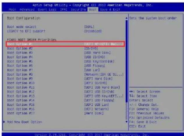
text_image
Auto Setup Utility - Copyright (C) 2017 American Megatrends, Inc. Main Advanced Event Logs IPM Security BOOT Save & Exit Boot Configuration Boot mode select [DUAL] LEGACY to EFI support [Disabled] FIXED BOOT ORDER Priorities Boot Option #1 [DEFI AP:DEFI: No...] Boot Option #2 [OSV/DVD] Boot Option #3 [USB Hard Disk] Boot Option #4 [USB CD/DVD] Boot Option #5 [USB Key:SSND[isk] Boot Option #6 [USB Floppy] Boot Option #7 [USB Lan] Boot Option #8 [Network:IDA GE SI...] Boot Option #9 [UEFI Hard Disk] Boot Option #10 [UEFI CD/DVD] Boot Option #11 [UEFI USB Hard Disk] Boot Option #12 [UEFI USB CD/DVD] Boot Option #13 [UEFI USB Key:UEFI...] Boot Option #14 [UEFI USB Floppy] Boot Option #15 [UEFI USB Lan] Boot Option #16 [DEFI Network] Boot Option #17 [Hard Disk] ▶ Pick New Boot Option Sets the system boot order <<: Select Screen T4: Select Item Enters Select +/-: Change Dot. F1: General) Help F2: Previous Values F3: Optimized Defaults F4: Save & Exit EOG: Exit Version 2.19.1266. Copyright (C) 2017 American Megatrends, Inc.- When the UEFI Shell prompt appears, type fs# to change the device directory path. Go to the directory that contains the BIOS package you extracted earlier from Step 6. Enter flash.nsh BIOSname.### at the prompt to start the BIOS update process.
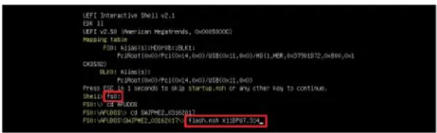
text_image
LEFI Interactive Shell v2.1 ESK 11 LEFI v2.50 (American Regatrends, 0x0089XXC) Mapping table: F30: A106(0):H0D(F0):BLK1; PcJW001(0x0)/PcI(0x14,0x0)/US$(0x11,0x0)/H01_MER_0xG7901D2_0xB06_0x1 OR3532) BLK0: Rile(s): PcJW001(0x0)/PcI(0x14,0x0)/US$(0x11,0x0) Press ESCR is 1 seconds to skip startup.msh or any other key to continue. Shell (f30) F30: CD BLKOS F30:VAFUOOS> CD SKAPME2_0362017 F30:VAFUOOS SKAPME2_0362017 flash.nsh X13P07.5XNote: Do not interrupt this process until the BIOS flashing is complete.
text_image
Done. [Access Ows Part Ex] Index 0x51: 0x18 Done. ********************************************************************** * Program BIOS and ME (including RDT) regions... ********************************************************************** AMI Firmware Update Utility v5.09.01.1317 Copyright ©2017 American Regatrends Inc. All Rights Reserved. OPUD = 50652 Reading Flash ....... done - ME Data Size checking . ok - PFS checksums ....... ok - Check RowLayout ....... ok, Erasing Boot Block ....... done Updating Boot Block ....... done Verifying Boot Block ....... done Zrading Mesh Block ....... 0x00152000 (00)- The screen above indicates that the BIOS update process is complete. When you see the screen above, unplug the AC power cable from the power supply, clear CMOS, and plug the AC power cable in the power supply again to power on the system.
text_image
Verifying HCB Book ....... done - Update success for FSK - Update success for EE - - Successful Update Recovery Loader to (PRx1) - Successful Update MFSB11- - Successful Update FTRM11- - Successful Update NFS, [081 and 19021] - Successful Update FLOD and UTOX11 - ML entire image update success ll WAVRNDK : System must power-off to have the changes take effect! Moving F501:AFUD005/SJPM2E_03162037/40x64,efi -> F501:AFUD005/SJPM2E_03162017-y df.sac - [c4] Moving F501:AFUD005/SJPM2E_03162037/aufemfix4,efi -> F501:AFUD005/SJPM2E_0316201 ?rafuefi.sac - [c4] ********************************************************************** * * Please ignore this 'Shell cannot read from file - device error' * Warning message due to it does not impact flashing process. * ********************************************************************** initating * Delete successful. F501->- Press
continuously to enter the BIOS Setup utility. - Press
to load the default settings. - After loading the default settings, press
to save the settings and exit the BIOS Setup utility.
Appendix E
IPMI Crash Dump
In the event of a processor internal error (IERR) that crashes your system, you may want to provide information to support staff. You can download a crash dump of status information using IPMI. The IPMI manual is available at https://www.supermicro.com/solutions/IPMI.cfm.
Check IPMI Error Log
- Access the IPMI web interface.
- Click the Server Health tab, then Event Log to verify an IERR error.
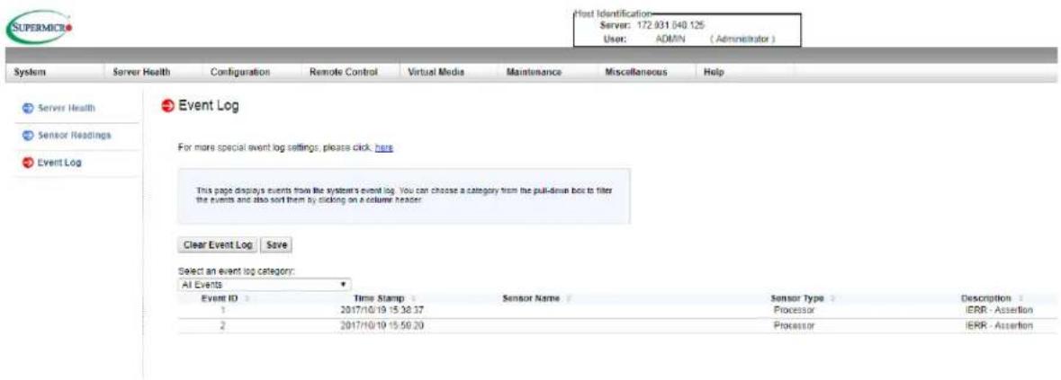
text_image
Host Identification Server: 172 831 640 125 User: ADMIN (Administrator) System Server Health Configuration Remote Control Virtual Media Maintenance Miscellaneous Help Server Health Sensor Readings Event Log Event Log For more special event log settings, please click here. This page displays events from the system's event log. You can choose a category from the pull-down box to filter the events and also sort them by clicking on a column header. Clear Event Log Save Select an event log category: All Events Event ID Time Stamp Sensor Name Sensor Type Description 1 2017/10/19 15:38:37 Processor IERR - Assertion 2 2017/10/19 15:50:20 Processor IERR - AssertionFigure E-1. IPMI Event Log
In the event of an IERR, the BMC executes a crash dump. You must download the crash dump and save it.
Downloading the Crash Dump File
- In the IPMI interface, click the Miscellaneous tab, then the Trouble Shooting option.
- Click the Dump button and wait five minutes for the file to be created. (No confirmation message will appear.)
- Click the Download button and a Save As dialog appears.
- Save the zipped dump file, noting the name and location.
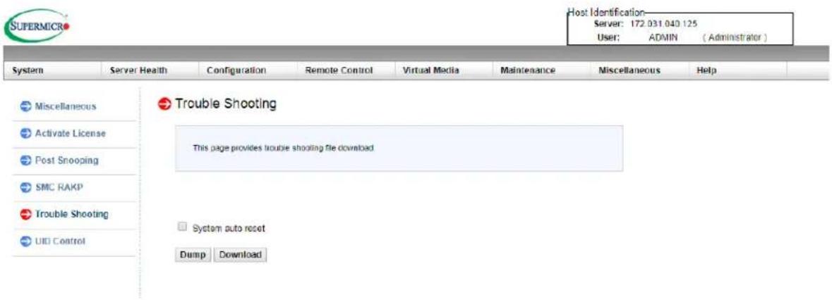
text_image
SUPERMICRO Host Identification Server: 172.031.040.125 User: ADMIN (Administrator) System Server Health Configuration Remote Control Virtual Media Maintenance Miscellaneous Help Miscellaneous Activate License Post Snooping SMC RAKP Trouble Shooting UID Control Trouble Shooting This page provides trouble shooting file download System auto reset Dump DownloadFigure E-2. IPMI Crash Dump Download
Note: The System auto reset check box dictates behavior after an IERR. If checked, the system will restart automatically, and the dump file will be erased. If not, the system remains in a failed state. Do not check this box until after the dump file has been sent to Support.
Appendix F
CPU-Based RAID for NVMe
Intel® Virtual RAID on CPU (Intel VROC) is an enterprise RAID solution for NVMe SSDs directly attached to Intel Xeon Scalable processors. Intel Volume Management Device (VMD) is an integrated controller inside the CPU PCI-E root complex.
- A single processor supports up to 12 NVMe SSDs and up to 6 RAID arrays.
- A dual processor system supports up to 24 NVMe SSDs and 12 RAID arrays.
Strip sizes are 4K, 8K, 16K, 32K, 64K, 128K.
Requirements and Restrictions
- Intel VROC is only available when the system is configured for UEFI boot mode.
- To enable the mdadm command and support for RSTe, install the patch from
- Linux: https://downloadcenter.intel.com/download/28158/Intel-Virtual-RAID-on-CPU-Intel-VROC-and-Intel-Rapid-Storage-Technology-enterprise-Intel-RSTe-Driver-for-Linux-
- Windows: https://downloadcenter.intel.com/download/28108/Intel-Virtual-RAID-on-CPU-Intel-VROC-and-Intel-Rapid-Storage-Technology-enterprise-Intel-RSTe-Driver-for-Windows-
- To enable Intel VROC, a hardware key must be inserted on the motherboard, and the appropriate processor's Virtual Management Devices must be enabled in the BIOS setup.
- It is possible to enable Intel VROC without a hardware key installed, but only RAID0 will be enabled.
- Intel VROC is not compatible with secure boot. This feature must be disabled.
- When creating bootable OS RAID1 devices, you must have both devices on the same CPU, and a VMD on that CPU.
- Spanning drives when creating RAID devices is not recommended due to performance issues, even though it is supported.
Supported SSDs and Operating Systems
To see the latest support information: https://www.intel.com/content/www/us/en/support/articles/000030310/memory-and-storage/ssd-software.html
Additional Information
Additional information is available on the product page for the Supermicro add-on card and the linked manuals.
www.supermicro.com/products/accessories/addon/AOC-VROCxxxMOD.cfm
F.1 Hardware Key
The Intel VROC hardware key is a license key that detects the Intel VROC SKU and activates the function accordingly. The key must be plugged into the Supermicro motherboard (connector JRK1). The key options are:
| Intel® VROC Keys | |||
| VROC Package Description Part Number Intel MM Number | |||
| Standard | RAID 0, 1, 10Supports 3rd party SSDs | AOC-VROCSTNMOD 95 | 1605 |
| Premium | RAID 0, 1, 5, 10Supports 3rd party SSDs | AOC-VROCPREMOD 95 | 1606 |
| Intel SSD only | RAID 0, 1, 5, 10Supports Intel SSDs only | AOC-VROCINTMOD 95 | 822 |
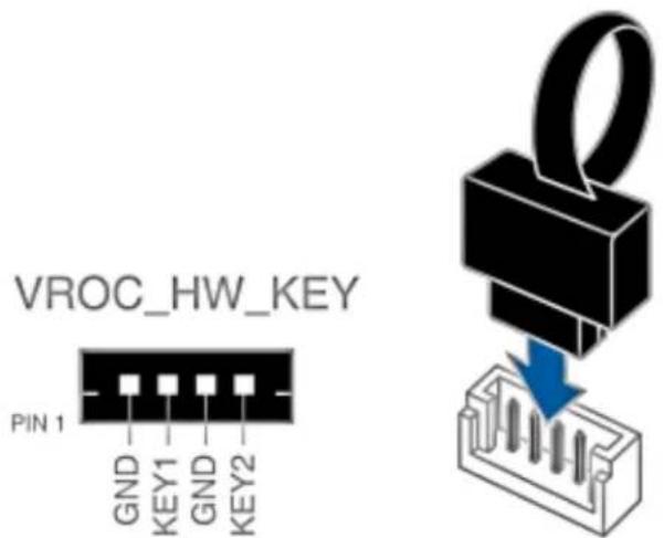
text_image
VROC_HW_KEY PIN 1 GND KEY1 GND KEY2Figure F-1. Intel® VROC RAID Key and Motherboard Connector JRK1
F.2 Enabling NVMe RAID
RAID for NVMe SSDs must be enabled through the UEFI BIOS.
- Install the patch as described in the Restrictions and Requirements section on a previous page.
- Reboot the server.
- Press [DEL] key to enter BIOS.
- Switch to Advanced > Chipset Configuration > North Bridge > IIO Configuration > Intel VMD Technology > Intel VMD for Volume Management on CPU2.
- Enable the VMD.
Enable VMD Config for PStack0 and PStack2 and enable all the sub-items under PStack0 and PStack2.
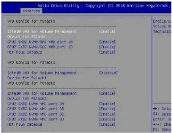
text_image
Apollo Setup Utility - Copyright (C) 2018 American Megatrends Advanced VMD Config for PStack0 Intel® VMD for volume Management [Enable] Device for PStack0 CPU2 SXE2 NAME/SAS VMD port 1B [Enable] CPU2 SXE2 NAME/SAS VMD port 1B [Enable] Hot Plug Capable [Enable] VMD Config for PStack1 Intel® VMD for volume Management [OLisable] Device for PStack1 VMD Config for PStack2 Intel® VMD for volume Management [Enable] Device for PStack2 CPU2 SXE2 NAME VMD port 3A [Enable] CPU2 SXE2 NAME VMD port 3B [Enable] CPU2 SXE2 NAME VMD port 3C [Enable] CPU2 SXE2 NAME VMD port 3D [Enable] Hot Plug Capable [Enable] Enable/0 Volume M Technolo ++: Sell F1: Sell Enter: S +/-: Cha F1: GenoFigure F-2. BIOS VMD Settings
- Press [F4] to save the configuration and reboot the system.
- Press [DEL] to enter BIOS.
- Switch to Advanced > Intel® Virtual RAID on CPU > All Intel VMD Controllers > Create RAID Volume.
- Set Name.
- Set RAID Level.
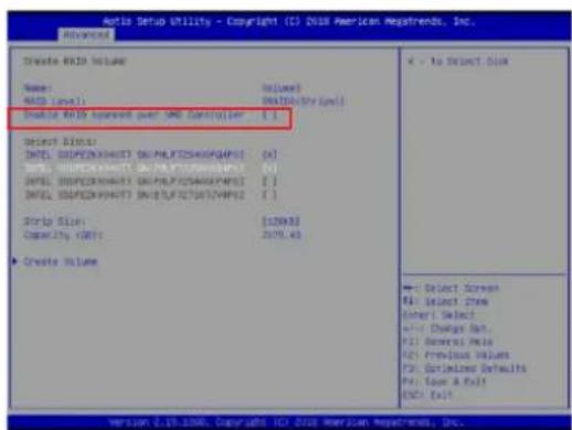
text_image
AutoCAD Utility - Copyright (C) 2018 American Markets, Inc. Advanced Create RAID Volume Name: BIAS Level: 0.0000 BIAS Level: 0.0000 Disable RAID spread over SMD Controller: [ ] Drive Base: BIAS SPEDENXHUSTO DOUTRFDZSHKQPAI52 (A) BIAS SPEDENXHUSTO DOUTRFDZSHKQPAI52 (B) BIAS SPEDENXHUSTO DOUTRFDZSHKQPAI52 (C) BIAS SPEDENXHUSTO DOUTRFDZSHKQPAI52 (D) Strip Size: [129MB] Capacity: [MB]: 3276.43 Create Volume ← To Select Disk → Select Screen File Select Item Enter Select +/- Change Rate +/- General Rate +/- Previous Value +/- Optimal Defaults File Save As Help OK! Exit Version 0.10.2000. Copyright: HCI 2018 American Markets, Inc.Figure F-3. Created Volume without enabling RAID spanned over VMD controller
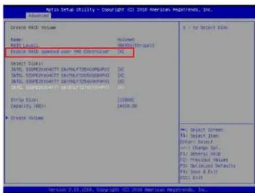
text_image
Auto Setup Utility - Copyright (C) 2008 American Markets, Inc. Advanced Create RMS Volume Name: HOLD LEVELS Volume: HOLD Destination Enable RMS speedout over HMI Controller: [AC] Select Display HDL STOPEXCHARTS SAUHALTY/SPAPPROPS HDL STOPEXCHARTS SAUHALTY/SPAPPROPS HDL STOPEXCHARTS SAUHALTY/SPAPPROPS HDL STOPEXCHARTS SAUHALTY/SPAPPROPS Strip Size: Capacity: 10000 Capacity: 14000.00 Create Volume X = to Select Disk Select Screen Select Item Enter Wizard +/- Change Del. F1: General Help F2: Precise Values F3: Default Defaults F4: Save A Exit F5: Exit Version 2.13, USA, Copyright 2008 American Markets, Inc.Figure F-4. Created Volume with enabling RAID spanned over VMD controller
- If cross-controller RAID is required, select Enable RAID spanned over VMD Controller as shown in Figure F-4.
- Select specific disks for RAID with an [X].
• RAID0: Select at least two [2 - 24] disks
• RAID1: Select only two disks
• RAID5: Select at least three [3 - 24] disks
• RAID10: Select only four disks
- Select Strip Size (Default 64KB).
- Select Create Volume.
- If another RAID is needed, start again at step 6.
- Press [F4] to save and reboot.
F.3 Status Indications
An LED indicator on the drive carrier shows the RAID status of the drive.
| Drive Carrier Status LED Indicator | |
| Status State (red) | |
| Normal function Off | |
| Locating 4 Hz blink | |
| Fault Solid on | |
| Rebuilding 1 Hz Blink | |
IBPI SFF 8489 Defined Status LED States
F.4 Hot Swap Drives
Intel VMD enables hot-plug and hot-unplug for NVMe SSDs, whether from Intel or other manufacturers. Under vSphere ESXi, several steps are necessary to avoid potential stability issues. See the information at link [1] below.
Hot-unplug
- Prevent devices from being re-detected during rescan:
esxcli storage core claiming autoclaim --enabled=false
- Unmount the VMFS volumes on the device. Check [2] for details.
- Detach the device. Check [3] for details.
- Physically remove the device.
Hot-plug
• Physically install the device.
ESXi will automatically discover NVMe SSDs, but a manual scan may be required in some cases.
Related Information Links
[1] https://kb.vmware.com/s/article/2151404
[2] https://docs.vmware.com/en/VMware-vSphere/6.5/com.vmware.vsphere.storage.doc/GUID-1B56EF97-F60E-4F21-82A7-8F2A7294604D.html
[3] https://docs.vmware.com/en/VMware-vSphere/6.5/com.vmware.vsphere.storage.doc/GUID-F2E75F67-740B-4406-9F0C-A2D99A698F2A.html