SuperServer SSG-110P-NTR10 - Server Supermicro - Free user manual and instructions
Find the device manual for free SuperServer SSG-110P-NTR10 Supermicro in PDF.

User questions about SuperServer SSG-110P-NTR10 Supermicro
0 question about this device. Answer the ones you know or ask your own.
Ask a new question about this device
Download the instructions for your Server in PDF format for free! Find your manual SuperServer SSG-110P-NTR10 - Supermicro and take your electronic device back in hand. On this page are published all the documents necessary for the use of your device. SuperServer SSG-110P-NTR10 by Supermicro.
USER MANUAL SuperServer SSG-110P-NTR10 Supermicro
natural_image
Front view of a black rack-mounted server unit with multiple NVMs drive bays and ports (no visible text or labels)USER'S MANUAL
Revision 1.0b
The information in this User's Manual has been carefully reviewed and is believed to be accurate. The vendor assumes no responsibility for any inaccuracies that may be contained in this document, and makes no commitment to update or to keep current the information in this manual, or to notify any person or organization of the updates. Please Note: For the most up-to-date version of this manual, please see our website at www.supermicro.com.
Super Micro Computer, Inc. ("Supermicro") reserves the right to make changes to the product described in this manual at any time and without notice. This product, including software and documentation, is the property of Supermicro and/or its licensors, and is supplied only under a license. Any use or reproduction of this product is not allowed, except as expressly permitted by the terms of said license.
IN NO EVENT WILL Super Micro Computer, Inc. BE LIABLE FOR DIRECT, INDIRECT, SPECIAL, INCIDENTAL, SPECULATIVE OR CONSEQUENTIAL DAMAGES ARISING FROM THE USE OR INABILITY TO USE THIS PRODUCT OR DOCUMENTATION, EVEN IF ADVISED OF THE POSSIBILITY OF SUCH DAMAGES. IN PARTICULAR, SUPER MICRO COMPUTER, INC. SHALL NOT HAVE LIABILITY FOR ANY HARDWARE, SOFTWARE, OR DATA STORED OR USED WITH THE PRODUCT, INCLUDING THE COSTS OF REPAIRING, REPLACING, INTEGRATING, INSTALLING OR RECOVERING SUCH HARDWARE, SOFTWARE, OR DATA.
Any disputes arising between manufacturer and customer shall be governed by the laws of Santa Clara County in the State of California, USA. The State of California, County of Santa Clara shall be the exclusive venue for the resolution of any such disputes. Supermicro's total liability for all claims will not exceed the price paid for the hardware product.
FCC Statement: This equipment has been tested and found to comply with the limits for a Class A or Class B digital device pursuant to Part 15 of the FCC Rules. These limits are designed to provide reasonable protection against harmful interference when the equipment is operated in industrial environment for Class A device or in residential environment for Class B device. This equipment generates, uses, and can radiate radio frequency energy and, if not installed and used in accordance with the manufacturer's instruction manual, may cause harmful interference with radio communications. Operation of this equipment in a residential area is likely to cause harmful interference, in which case you will be required to correct the interference at your own expense.
California Best Management Practices Regulations for Perchlorate Materials: This Perchlorate warning applies only to products containing CR (Manganese Dioxide) Lithium coin cells. "Perchlorate Material-special handling may apply. See www.dtsc.ca.gov/hazardouswaste/perchlorate".

WARNING: This product can expose you to chemicals including lead, known to the State of California to cause cancer and birth defects or other reproductive harm. For more information, go to www.P65Warnings.ca.gov.
The products sold by Supermicro are not intended for and will not be used in life support systems, medical equipment, nuclear facilities or systems, aircraft, aircraft devices, aircraft/emergency communication devices or other critical systems whose failure to perform be reasonably expected to result in significant injury or loss of life or catastrophic property damage. Accordingly, Supermicro disclaims any and all liability, and should buyer use or sell such products for use in such ultra-hazardous applications, it does so entirely at its own risk. Furthermore, buyer agrees to fully indemnify, defend and hold Supermicro harmless for and against any and all claims, demands, actions, litigation, and proceedings of any kind arising out of or related to such ultra-hazardous use or sale.
Manual Revision 1.0b
Release Date: December 04, 2023
Unless you request and receive written permission from Super Micro Computer, Inc., you may not copy any part of this document. Information in this document is subject to change without notice. Other products and companies referred to herein are trademarks or registered trademarks of their respective companies or mark holders.
Copyright © 2023 by Super Micro Computer, Inc.
All rights reserved.
Printed in the United States of America
Preface
About this Manual
This manual is written for professional system integrators and PC technicians. It provides information for the installation and use of the server. Installation and maintenance should be performed by certified service technicians only.
Please refer to the SSG-110P-NTR10/NTR10-EU server specifications page on our website for updates on supported memory, processors and operating systems (http://www.supermicro.com).
Notes
For your system to work properly, please follow the links below to download all necessary drivers/utilities and the user's manual for your server.
• Supermicro product manuals: http://www.supermicro.com/support/manuals/
• Product drivers and utilities: https://www.supermicro.com/wdl
- Product safety info: http://www.supermicro.com/about/policies/safety_information.cfm
If you have any questions, please contact our support team at:
support@supermicro.com
This manual may be periodically updated without notice. Please check the Supermicro website for possible updates to the manual revision level.
Secure Data Deletion
A secure data deletion tool designed to fully erase all data from storage devices can be found on our website: https://www.supermicro.com/about/policies/disclaimer.cfm?url=/wdl/utility/Lot9_Secure_Data_Deletion_Utility/
Warnings
Special attention should be given to the following symbols used in this manual.

Warning! Indicates important information given to prevent equipment/property damage or personal injury.

Warning! Indicates high voltage may be encountered when performing a procedure.
Contents
Chapter 1 Introduction
1.1 Overview....9
1.2 System Features ....10
Control Panel....11
Rear View....12
1.3 System Architecture ....13
Board Location....13
1.4 Motherboard Layout....14
Quick Reference Table....15
Motherboard Block Diagram ....17
Chapter 2 Server Installation
2.1 Overview....18
2.2 Unpacking the System....18
2.3 Preparing for Setup....18
Choosing a Setup Location....18
Rack Precautions....19
Server Precautions....19
Rack Mounting Considerations....19
Ambient Operating Temperature....19
Airflow 20
Mechanical Loading....20
Circuit Overloading....20
Reliable Ground....20
2.4 Installing the Rails....22
Identifying the Rails....22
Installing the Inner Rails ....23
Assembling the Outer Rails ....24
Installing the Outer Rails....25
2.5 Installing into the Rack....26
Installing the Server onto a Telco Rack....27
Chapter 3 Maintenance and Component Installation
3.1 Removing Power....28
3.2 Accessing the System....28
3.3 Processor and Heatsink Installation....30
The Processor Carrier Assembly ....31
The Processor Heatsink Module (PHM)....33
Installing the PHM into the CPU Socket....34
Removing the PHM from the CPU Socket ....37
Removing the Processor Carrier Assembly from the PHM 38
Removing the Processor from the Carrier Assembly....39
3.4 Memory....40
General Guidelines for Optimizing Memory Performance 41
DIMM Installation 42
DIMM Removal 42
3.5 Motherboard Battery....43
3.6 Storage Drives....44
NVMe Drives 44
NVMe Drive Carrier Indicators 44
Installing an M.2 Solid State Drive....47
Hot-Swap for NVMe Drives....49
Checking the Temperature of an NVMe Drive 50
PCI Expansion Card Installation....51
3.7 System Cooling ....53
Changing a System Fan ....53
Air Shroud ....54
Checking the Airflow ....54
3.8 Power Supply ....55
Power Supply Failure ....55
3.9 Cable Routing Diagram....56
3.10 BMC Reset....57
Chapter 4 Motherboard Connections
4.1 Power Connections ....58
4.2 Headers and Connectors ....60
Control Panel....65
4.3 Input/Output Ports 68
4.4 Jumpers....71
How Jumpers Work....71
4.5 LED Indicators....73
Chapter 5 Software
5.1 Microsoft Windows OS Installation....75
5.2 Driver Installation....77
5.3 SuperDoctor ^® 5....78
5.4 BMC....79
BMC ADMIN User Password ....79
Chapter 6 Optional Components
6.1 Optional Parts List....80
6.2 TPM Security Module....80
6.3 Intel Virtual RAID on CPU (VROC)....81
Requirements and Restrictions....81
Supported SSDs and Operating Systems 81
Additional Information 82
Hardware Key 82
Enabling NVMe RAID....83
Status Indications....85
Hot Swap Drives 85
Hot-unplug 85
Hot-plug 85
Chapter 7 Troubleshooting and Support
7.1 Information Resources ....86
Website 86
Direct Links for the SSG-110P-NTR10/NTR10-EU System 86
Direct Links for General Support and Information 86
7.2 Baseboard Management Controller (BMC)....87
7.3 Troubleshooting Procedures .....88
General Technique....88
No Power 88
No Video 89
System Boot Failure 89
Memory Errors 89
Losing the System Setup Configuration ....89
When the System Becomes Unstable....89
7.4 BIOS Error Beep (POST) Codes .....91
Additional BIOS POST Codes 91
7.5 Crash Dump Using BMC....92
7.6 UEFI BIOS Recovery 93
Overview 93
Recovering the UEFI BIOS Image....93
Recovering the Main BIOS Block with a USB Device....93
7.7 CMOS Clear....98
7.8 Where to Get Replacement Components....99
7.9 Reporting an Issue....99
Technical Support Procedures....99
Returning Merchandise for Service....99
Vendor Support Filing System ....100
7.10 Feedback....100
Appendix A Standardized Warning Statements for AC Systems Appendix B System Specifications
Contacting Supermicro
Headquarters
Address: Super Micro Computer, Inc.
980 Rock Ave.
San Jose, CA 95131 U.S.A.
Tel: +1 (408) 503-8000
Fax: +1 (408) 503-8008
Email: marketing@supermicro.com (General Information)
Sales-USA@supermicro.com (Sales Inquiries)
Government_Sales-USA@supermicro.com (Gov. Sales Inquiries)
support@supermicro.com (Technical Support)
RMA@supermicro.com (RMA Support)
Webmaster@supermicro.com (Webmaster)
Website: www.supermicro.com
Europe
Address: Super Micro Computer B.V.
's-Hertogenbosch, The Netherlands
Tel: +31 (0) 73-6400390
Fax: +31 (0) 73-6416525
Email: Sales_Europe@supermicro.com (Sales Inquiries)
Support_Europe@supermicro.com (Technical Support)
RMA_Europe@supermicro.com (RMA Support)
Website: www.supermicro.nl
Asia-Pacific
Address: Super Micro Computer, Inc.
3F, No. 150, Jian 1st Rd.
Zhonghe Dist., New Taipei City 235
Taiwan (R.O.C)
Tel: +886-(2) 8226-3990
Fax: +886-(2) 8226-3992
Email: Sales-Asia@supermicro.com.tw (Sales Inquiries)
Support@supermicro.com.tw (Technical Support)
RMA@supermicro.com.tw (RMA Support)
Website: www.supermicro.com.tw
Chapter 1
Introduction
1.1 Overview
This chapter provides a brief outline of the functions and features of the SuperServer SSG-110P-NTR10/NTR10-EU. It is based on the X12SPO-NTF motherboard and the CSE-116TS-R860CBP-N10/RCNBP-N10 chassis.
The following provides an overview of the specifications and capabilities.
| System Overview | |
| Motherboard | X12SPO-NTF |
| Chassis | SSG-110P-NTR10: CSE-116TS-R860CBP-N10SSG-110P-NTR10-EU: CSE-116TS-RCNBP-N10 |
| Processor Support | Single 3rd generation Intel Xeon Scalable Processor (Socket P+ (LGA4189)) with up to 40 cores and a thermal design power (TDP) of up to 270 W |
| Chipset | Intel PCH C621A (LBG-R) |
| Memory | Supports up to 2048 GB of ECC RDIMM/LRDIMM/LRDIMM (3DS) with speeds up to 3200 MHz in eight slots |
| Drive Support | Ten front 2.5" hot-swap U.2 NVMe drivesTwo onboard M.2 PCIe 3.0 x4/SATA3 slot |
| Expansion Slots | One PCIe 4.0 x16 FHHL slot |
| Networking | Dual 10G BASE-T Ports via Intel Ethernet Controller X550One Dedicated BMC LAN located on the rear I/O panel |
| I/O Ports | One serial port on the rear I/O panel (COM1)One serial port header (COM2)Two SATA 3.0 ports with SATA DOM power (S-SATA0, S-SATA1)One VGA connection on the rear I/O panel |
| System Cooling | Six cooling fans |
| Power | SSG-110P-NTR10: Redundant 860 W power supplies, 80Plus level PlatinumSSG-110P-NTR10-EU: Redundant 860 W power supplies, 80Plus level Titanium |
| Form Factor | 1U rackmount; (WxHxD) 17.2 x 1.7 x 23.5 in (437 x 43 x 597 mm) |
A Quick Reference Guide can be found on the product page of the Supermicro website. The following safety agency or regulatory models associated with the SSG-110P-NTR10/NTR10-EU have been certified as compliant with CSA or UL: 116-8 or 116-R8X12.
1.2 System Features
The CSE-116TS-R860CBP-N10/RCNBP-N10 is a 1U chassis that supports ten front hot-swappable U.2 NVMe drives.
Front View
The chassis front offers access to the storage drives and a control panel for each node.
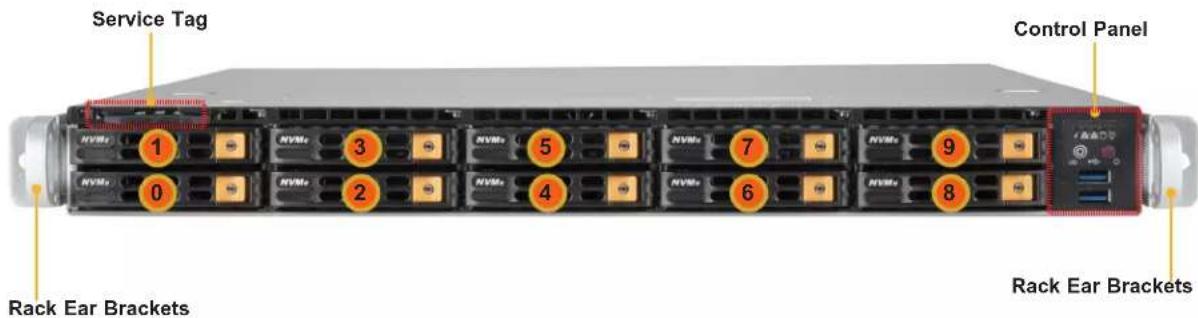
text_image
Service Tag Control Panel Rack Ear Brackets 1 2 3 4 5 6 7 8 9 0 NVMs NVMs NVMs NVMs NVMs NVMs NVMs NVMs NVMs NVMsFigure 1-1. Front View
| System Features: Front | |
| Feature Description | |
| Service Tag Pull-out service tag with BMC password label. | |
| 0, 1, etc. | Ten drive bays for 2.5" hot-swap NVMe drive carriers. |
| Control Panels Control panel for the server. See the Control Panel section on the next page. | |
| Rack Ear Brackets Secures the server chassis to the rack. | |

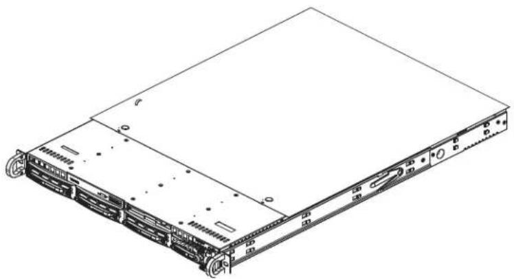
natural_image
Technical line drawing of a server rack with two views: top view showing internal components and side view (no text or symbols)Figure 1-2. Location of Service Tag
Control Panel
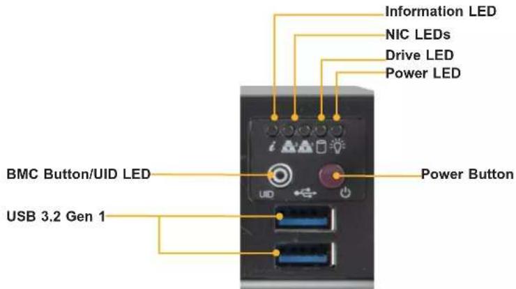
text_image
Information LED NIC LEDs Drive LED Power LED BMC Button/UID LED USB 3.2 Gen 1 Power ButtonFigure 1-3. Control Panel
| Control Panel Features | |
| Feature Description | |
| Power Button | The main power switch applies or removes primary power from the power supply to the server but maintains standby power. |
| NIC LEDs Indicates network activity on the LAN when flashing. | |
| Information LED Information LED (see table below for details). | |
| Drive LED Indicates drive activity when flashing. | |
| Power LED | Indicates power is being supplied to the system's power supply units. This LED should normally be illuminated when the system is operating. |
| BMC Button/UID LED | The BMC reset button resets the BMC firmware when pressed. The unit identification (UID) button turns on or off the blue light function of the Information LED and a blue LED on the rear of the chassis. These are used to locate the server in large racks and server banks. |
| USB ports Two USB 3.2 Gen 1 ports | |
| Information LED | |
| Color, Status Description | |
| Red, solid An overheat condition has occurred. | |
| Red, blinking at 1 Hz Fan failure, check for an inoperative fan. | |
| Red, blinking at 0.25 Hz Power failure, check for a non-operational power supply. | |
| Red, solid, with Power LED blinking green Fault detected | |
| Blue and red, blinking at 10 Hz Recovery mode | |
| Blue, solid | UID has been activated locally to locate the server in a rack environment. |
| Blue, blinking at 1 Hz | UID has been activated using the BMC to locate the server in a rack environment. |
| Blue, blinking at 2 Hz BMC is resetting | |
| Blue, blinking at 4 Hz BMC is setting factory defaults | |
| Blue, blinking at 10 Hz with Power LED blinking green | BMC/BIOS firmware is updating |
Rear View
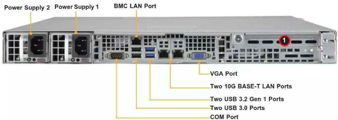
text_image
Power Supply 2 Power Supply 1 BMC LAN Port VGA Port Two 10G BASE-T LAN Ports Two USB 3.2 Gen 1 Ports Two USB 3.0 Ports COM PortFigure 1-4. System: Rear View
| System Features: Rear | |
| Feature Description | |
| Power Supplies Two 860 W redundant power supplies | |
| LAN Ports Two 10G BASE-T LAN and one dedicated BMC LAN port | |
| USB Ports Two USB 3.2 Gen 1 ports and two USB 2.0 ports | |
| COM Port Serial COM port | |
| VGA Port Video port |
| Expansion Slot Locations | |
| Item Description | |
| 1 Slot for FHHL expansion (add-on) card | |
CPU1
1.3 System Architecture
This section covers the printed circuit board (PCB) locations.
Board Location
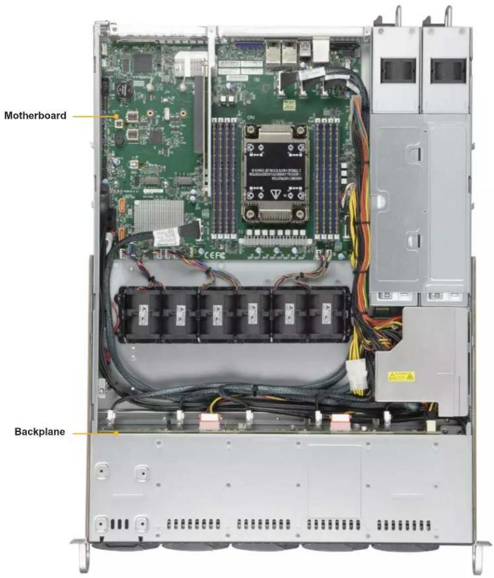
text_image
Motherboard BackplaneFigure 1-5. Board Location
1.4 Motherboard Layout
Below is a layout of the X12SPO-NTF motherboard with jumper, connector and LED locations shown. See the table on the following page for descriptions. For detailed descriptions, pinout information and jumper settings, refer to Chapter 4 or the Motherboard Manual.

text_image
BMC Password Label BMC ACIFQBCQBDIAC PWD SIOKJNTEO UID SW USB6/7 (3.2 Gen 1) JNCSI1 SLOT6 JPL1 LED2 VGA LAN2 LAN1 BMCI_LAN USB0/1 JPN1 COM1 FAN5 JSEN1 JIPMB1 JSTBY1 BMC_HB_LED COM2 BT1 JCPLD1 JNVI2C1 JVRM1 JWD1 LED_CATERR JD1 SP1 USB2/3 USB4/5 JTPM1 M.2-H_1 USB8/9 (3.2 Gen 1) M.2-H_2 S-SATA0 JSD1 I-SATA0~3 I-SATA4~7 JSD2 JL1 S_SATA1 JF1 POWER_LED JLED1 FANB USB10 (3.2 Gen 1) SUPERX12SPO-NTF/FREV: 2.0 DESIGNED IN USA SVM0000000000000000000000000000000000000000000000000000000000000000000000000000000000000000000000000000 NVM6/7 (3.2 Gen 1) SVM1A MASCAR OCEE SVM2 MASCAR OCEE SVM3 MASCAR OCEE SVM4 MASCAR OCEE SVM5 MASCAR OCEE SVM6 MASCAR OCEE SVM7 MASCAR OCEE SVM8 MASCAR OCEE SVM9 MASCAR OCEE SVM10 MASCAR OCEE SVM11 MASCAR OCEE SVM12 MASCAR OCEE SVM13 MASCAR OCEE SVM14 MASCAR OCEE SVM15 MASCAR OCEE SVM16 MASCAR OCEE SVM17 MASCAR OCEE SVM18 MASCAR OCEE SVM19 MASCAR OCEE SVM20 MASCAR OCEE SVM21 MASCAR OCEE SVM22 MASCAR OCEE SVM23 MASCAR OCEE SVM24 MASCAR OCEE SVM25 MASCAR OCEE SVM26 MASCAR OCEE SVM27 MASCAR OCEE SVM28 MASCAR OCEE SVM29 MASCAR OCEE SVM30 MASCAR OCEE SVM31 MASCAR OCEE SVM32 MASCAR OCEE SVM33 MASCAR OCEE SVM34 MASCAR OCEE SVM35 MASCAR OCEE SVM36 MASCAR OCEE SVM37 MASCAR OCEE SVM38 MASCAR OCEE SVM39 MASCAR OCEE SVM40 MASCAR OCEE SVM41 MASCAR OCEE SVM42 MASCAR OCEE SVM43 MASCAR OCEE SVM44 MASCAR OCEE SVM45 MASCAR OCEE SVM46 MASCAR OCEE SVM47 MASCAR OCEE SVM48 MASCAR OCEE SVM49 MASCAR OCEE SVM50 MASCAR OCEE SVM51 MASCAR OCEE SVM52 MASCAR OCEE SVM53 MASCAR OCEE SVM54 MASCAR OCEE SVM55 MASCAR OCEE SVM56 MASCAR OCEE SVM57 MASCAR OCEE SVM58 MASCAR OCEE SVM59 MASCAR OCEE SVM60 MASCAR OCEE SVM61 MASCAR OCEE SVM62 MASCAR OCEE SVM63 MASCAR OCEE SVM64 MASCAR OCEE SVM65 MASCAR OCEE SVM66 MASCAR OCEE SVM67 MASCAR OCEE SVM68 MASCAR OCEE SVM69 MASCAR OCEE SVM70 MASCAR OCEE SVM71 MASCAR OCEE SVM72 MASCAR OCEE SVM73 MASCAR OCEE SVM74 MASCAR OCEE SVM75 MASCAR OCEE SVM76 MASCAR OCEE SVM77 MASCAR OCEE SVM78 MASCAR OCEE SVM79 MASCAR OCEEFigure 1-6. Motherboard Layout
Quick Reference Table
Jumper Description Default Setting
| JBT1 CMOS Clear Open (Normal) | |
| JPL1 LAN1/LAN2 Enable | Pins 1-2 (Enabled) |
| Pins 2-3 (Disabled) | |
| JPME2 ME Manufacturing Mode Pins 1-2 (Normal) | |
| JWD1 Watch Dog Timer | Pins 1-2 (Reset) |
| Pins 2-3 (NMI) | |
LED Description Status
| BMC_HB_LED BMC Heartbeat LED Blinking Green: BMC Normal | ||
| LED2 Unit Identifier (UID) LED Solid Blue: Unit Identified | ||
| LED_CATERR | CARTERR LED | Solid Orange: System CARTERR (Catastrophic error) |
| POWER_LED | Onboard Power LED | Solid Green: Power On |
Connector Description
| BT1 | Onboard CMOS Battery(To Clear CMOS, remove the battery, short pins 1-2 for more than 10 seconds and install the battery.) |
| COM1/COM2 | COM Port/COM Header |
| FAN1~FAN5, FANA, FANB | CPU/System Fan Headers |
| BMC_LAN | Dedicated BMC 2.0 LAN Port |
| I-SATA0 ~ I-SATA7 | Intel® PCH SATA 3.0 Ports (with RAID 0, 1, 5, 10) |
| JD1 | Speaker/Buzzer Header (Pins 1-4: Speaker) |
| JF1 | Front Control Panel Header |
| JIPMB1 | 4-pin BMC External I2C Header (for an BMC card) |
| JL1 | Chassis Intrusion Header |
| JNCSI1 | NC-SI Header for BMC Support |
| JNVI2C1 | NVMe I2C Header |
| JPI2C1 | Power Supply SMBus I2C Header |
| JPWR1 | 24-pin ATX Power Connector |
| JPWR2 | 8-pin Power Connector |
| JPWR3 | 4-pin Power Connector |
| JRK1 | Intel RAID Key Header |
| JSD1, JSD2 | SATA DOM Power Connectors |
| JSEN1 | System Front Intel Temperature Sensor Header |
| JSTBY1 | Standby Power Header |
| JTPM1 | Trusted Platform Module/Port 80 Connector |
| LAN1, LAN2 LAN 10G/1G Base-T (Intel X550 for 10G [-NTF] or I350 for 1G [-F]) Ports | |
| M.2-H_1, M.2-H_2 | M.2 M-Key 2280/22110 (supports PCIe 3.0 x4/SATA3) Slot |
Connector Description
NVMe0\~9 PCIe 4.0 x8 Slimline SAS Connectors (NVMe4\~9 for -NTF only)
SLOT6 CPU PCIe 4.0 x16 Slot
SP1 Onboard Buzzer
S-SATA0, S-SATA1 SATA 3.0 Ports with SATA DOM Power
S-SGPIO1 Serial Link General Purpose I/O Connection Header
UID Unit Identifier (UID) Switch
USB0/1 Back Panel Universal Serial Bus (USB) 2.0 Ports
USB2/3, USB4/5 Front Access USB 2.0 Headers
USB6/7 Back Panel USB 3.2 Gen 1 Ports
USB8/9 Front Accessible USB 3.2 Gen 1 Header
USB10 USB 3.2 Gen 1 Type-A Header
VGA VGA Port
Motherboard Block Diagram
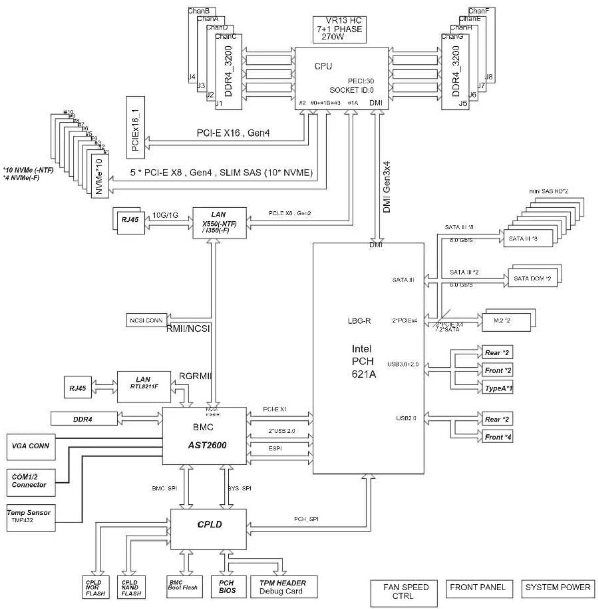
flowchart
graph TD
    subgraph CPU
        A["CPU PECI:30 SOCKET ID:0"] -->|PCI-E X16, Gen4| B["PCIEX16_1"]
        A -->|PCI-E X8, Gen4, SLIM SAS (10* NVME)| C["NVMe*10"]
        A -->|DMI Gen3x4| D["RJ45"]
        D --> E["LAN X550(-NTF) / I350(-F)"]
        E --> F["RJ45"]
        F --> G["LAN RTL8211F"]
        G --> H["BMC AST2600"]
        H --> I["DDR4"]
        I --> J["VGA CONN"]
        J --> K["COM1/2 Connector"]
        K --> L["Temp Sensor TMP432"]
        H --> M["CPLD"]
        M --> N["CPLD NOR FLASH"]
        M --> O["CPLD NAND FLASH"]
        M --> P["BMC Boot Flash"]
        M --> Q["PCH BIOS"]
        M --> R["TPM HEADER Debug Card"]
    end

    subgraph PLC
        S["LDG-R Intel PCH 621A"] --> T["SATA III"]
        S --> U["2*PCIEX4"]
        S --> V["USB3.0+2.0"]
        S --> W["USB2.0"]
    end

    subgraph Memory
        X["RAMII/NCSI"] --> Y["RGRMI"]
        Y --> Z["RCSE F23600"]
        AA["PCI-E X1"] --> AB["2*USB 2.0"]
        AC["ESPI"] --> AD["PCHE SPI"]
    end

    subgraph Control
        AE["MINI SAS HD*2"] --> AF["SATA III *8"]
        AE --> AG["SATA III *8"]
        AE --> AH["SATA III *2"]
        AE --> AI["SATA DOM *2"]
        AE --> AJ["M.2 *2"]
        AK["Rear *2"] --> AL["Front *2"]
        AK --> AM["TypeA*1"]
        AN["Rear *2"] --> AO["Front *4"]
    end

    subgraph System Power
        AP["FAN SPEED CTRL"] --> AQ["FRONT PANEL"] --> AR["SYSTEM POWER"]
    end
Figure 1-7. Motherboard Block Diagram
Chapter 2
Server Installation
2.1 Overview
This chapter provides advice and instructions for mounting your system in a server rack. If your system is not already fully integrated with processors, system memory etc., refer to Chapter 3 for details on installing those specific components.
Caution: Electrostatic Discharge (ESD) can damage electronic components. To prevent such damage to PCBs (printed circuit boards), it is important to use a grounded wrist strap, handle all PCBs by their edges and keep them in anti-static bags when not in use.
2.2 Unpacking the System
Inspect the box in which the SuperServer SSG-110P-NTR10/NTR10-EU was shipped, and note if it was damaged in any way. If any equipment appears damaged, file a damage claim with the carrier who delivered it.
Decide on a suitable location for the rack unit that will hold the server. It should be situated in a clean, dust-free area that is well ventilated. Avoid areas where heat, electrical noise and electromagnetic fields are generated. It will also require a grounded AC power outlet nearby. Be sure to read the precautions and considerations noted in Appendix A.
2.3 Preparing for Setup
The box in which the system was shipped should include the rackmount hardware needed to install it into the rack. Please read this section in its entirety before you begin the installation.
Choosing a Setup Location
- The system should be situated in a clean, dust-free area that is well ventilated. Avoid areas where heat, electrical noise and electromagnetic fields are generated.
- Leave enough clearance in front of the rack so that you can open the front door completely (approximately 25 inches) and approximately 30 inches of clearance in the back of the rack to allow sufficient space for airflow and access when servicing.
- This product should be installed only in a Restricted Access Location (dedicated equipment rooms, service closets, etc.).
- This product is not suitable for use with visual display workplace devices according to §2 of the German Ordinance for Work with Visual Display Units.
Rack Precautions
- Ensure that the leveling jacks on the bottom of the rack are extended to the floor so that the full weight of the rack rests on them.
- In single rack installations, stabilizers should be attached to the rack. In multiple rack installations, the racks should be coupled together.
- Always make sure the rack is stable before extending a server or other component from the rack.
- You should extend only one server or component at a time - extending two or more simultaneously may cause the rack to become unstable.
Server Precautions
- Review the electrical and general safety precautions in Appendix A.
- Determine the placement of each component in the rack before you install the rails.
- Install the heaviest server components at the bottom of the rack first and then work your way up.
- Use a regulating uninterruptible power supply (UPS) to protect the server from power surges and voltage spikes and to keep your system operating in case of a power failure.
- Allow any drives and power supply modules to cool before touching them.
- When not servicing, always keep the front door of the rack and all covers/panels on the servers closed to maintain proper cooling.
- To maintain proper cooling, always keep all chassis panels closed and all SATA carriers installed when not being serviced.
Rack Mounting Considerations
Ambient Operating Temperature
If installed in a closed or multi-unit rack assembly, the ambient operating temperature of the rack environment may be greater than the room's ambient temperature. Therefore, consideration should be given to installing the equipment in an environment compatible with the manufacturer's maximum rated ambient temperature (TMRA).
Airflow
Equipment should be mounted into a rack so that the amount of airflow required for safe operation is not compromised.
Mechanical Loading
Equipment should be mounted into a rack so that a hazardous condition does not arise due to uneven mechanical loading.
Circuit Overloading
Consideration should be given to the connection of the equipment to the power supply circuitry and the effect that any possible overloading of circuits might have on overcurrent protection and power supply wiring. Appropriate consideration of equipment nameplate ratings should be used when addressing this concern.
Reliable Ground
A reliable ground must be maintained at all times. To ensure this, the rack itself should be grounded. Particular attention should be given to power supply connections other than the direct connections to the branch circuit (i.e. the use of power strips, etc.).

To prevent bodily injury when mounting or servicing this unit in a rack, you must take special precautions to ensure that the system remains stable. The following guidelines are provided to ensure your safety:
- This unit should be mounted at the bottom of the rack if it is the only unit in the rack.
- When mounting this unit in a partially filled rack, load the rack from the bottom to the top with the heaviest component at the bottom of the rack.
- If the rack is provided with stabilizing devices, install the stabilizers before mounting or servicing the unit in the rack.
- Slide rail mounted equipment is not to be used as a shelf or a work space.

Warning: Do not pick up the server with the front handles. They are designed to pull the system from a rack only.

Slide rail mounted equipment is not to be used as a shelf or a work space.
2.4 Installing the Rails
There are a variety of rack units on the market, which may require a slightly different assembly procedure. This rail set fits a rack between 25.6" and 33" deep.
The following is a basic guideline for installing the system into a rack with the rack mounting hardware provided. You should also refer to the installation instructions that came with the specific rack you are using.
Identifying the Rails
The inner and outer rails comes in pairs and are labeled left and right. The outer rail includes a front and rear bracket as well as a middle rail that can be extended.

text_image
Inner Rail Middle Rail (not shown)-- slides forward from the outer rail Outer Rail, Front and Rear BracketsFigure 2-1. Inner and Outer Rails
Installing the Inner Rails
Installing the Inner Rails to the Chassis
- Place the correct rail on the side of the chassis, aligning the hooks of the chassis with the inner rail holes. Make sure the rail faces "outward" so that it will fit the rack's mounting bracket.
- Slide the rail toward the front of the chassis to hook the inner rail onto the side of the chassis.
- If desired, secure the rail with a flat head M4 x 4mm screw.
- Repeat for the other rail.
natural_image
Line drawing of a server rack unit with multiple drive bays and ventilation slots (no text or labels)Figure 2-2. Installing the Inner Rails to the Chassis
Assembling the Outer Rails
Each outer rail comes in two sections that must be assembled before mounting onto the rack.
Assembling the Outer Rails
-
Identify the left and right outer rails by examining the ends, which bend outward. Match the left front outer rail with the left rear outer rail and the same for the right rails.
-
Align the round post in the rear rail (B) with the round hole at the end of the slot in the front rail (A), and slide the front section into the rear section.
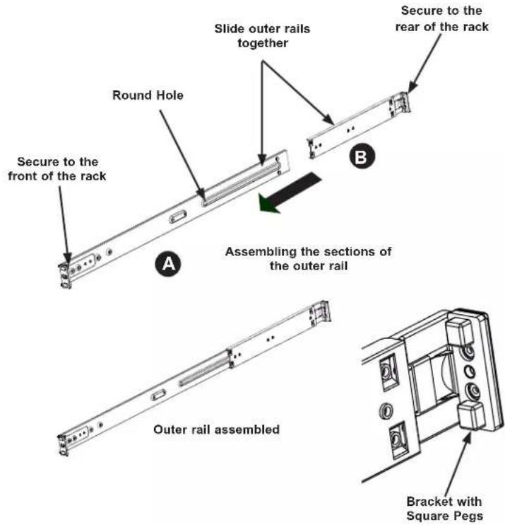
text_image
Secure to the front of the rack Round Hole Slide outer rails together Secure to the rear of the rack Assembling the sections of the outer rail Outer rail assembled Bracket with Square PegsFigure 2-3. Assembling the Outer Rails
Installing the Outer Rails
Each end of the assembled outer rail includes a bracket with square pegs to fit into your rack. Outer Rail Installation
- Align the square pegs on the front end of the rail with the square holes on the front of the rack (C). Push the rail into the rack until the quick release bracket snaps into place, securing the rail to the rack. Keep the rail horizontal.
- Adjust the rail to reach just past the full depth of your rack.
- Align the square pegs on the rear end of the rail to the holes on the rack (D) and push the rail into the rack until the quick release bracket snaps into place, securing the rail to the rack.
- Repeat the procedure for the other outer rail assembly.

natural_image
Isometric line drawing of a multi-tiered server rack cabinet with labeled components (no text or symbols beyond labels)Figure 2-4. Installing the Outer Rails to the Rack
2.5 Installing into the Rack
You should now have rails attached to both the chassis and the rack. The next step is to install the server into the rack.
Installing the Chassis into a Rack
- Confirm that chassis includes the inner rails. Also confirm that the outer rails are installed on the rack.
- Align the chassis inner rails with the front of the outer rails on the rack.
- Slide the chassis rails into the rack rails, keeping the pressure even on both sides (you may have to depress the locking tabs when inserting). When the server has been pushed completely into the rack, you should hear the locking tabs click into position.
- (Optional) Insert and tighten the thumbscrews that hold the front of the server to the rack.
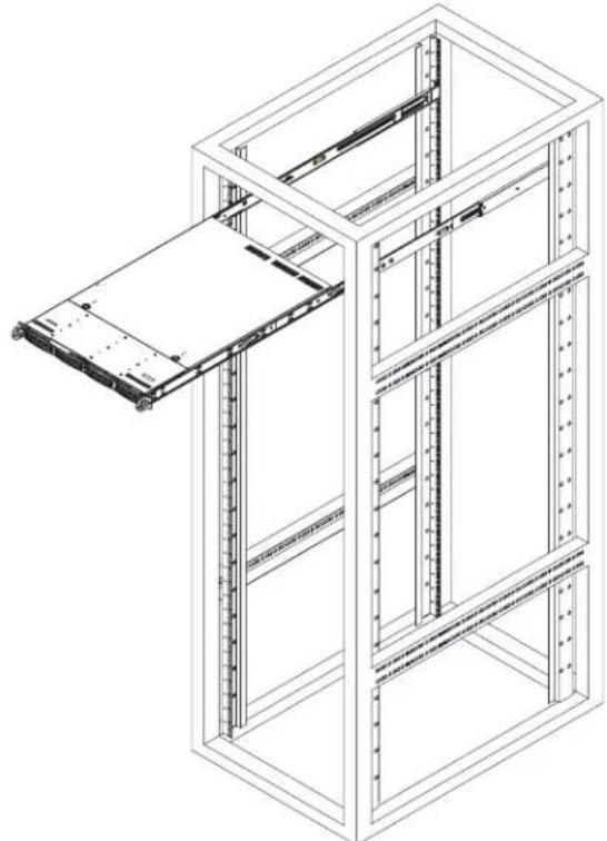
natural_image
Isometric line drawing of a server rack cabinet with an open panel (no text or symbols)Figure 2-5. Installing the Server into a Rack
Note: Figure is for illustrative purposes only. Always install servers to the bottom of a rack first.

Warning: Do not pick up the server with front handles. They are designed to pull the system from a rack only.

Stability hazard. The rack stabilizing mechanism must be in place, or the rack must be bolted to the floor before you slide the unit out for servicing. Failure to stabilize the rack can cause the rack to tip over.
Installing the Server onto a Telco Rack
To install the chassis into a Telco or post-style rack, use two L-shaped brackets on either side of the chassis (four total). First, determine how far follow the server will extend out the front of the rack. Larger chassis should be positioned to balance the weight between front and back. If a bezel is included on your server, remove it. Then attach the two front brackets to each side of the chassis, then the two rear brackets positioned with just enough space to accommodate the width of the telco rack. Finish by sliding the chassis into the rack and tightening the brackets to the rack.

natural_image
Isometric line drawing of a vertical structural frame with a horizontal support and internal components (no text or symbols)Figure 2-6. Installing the Server into a Telco Rack
Note: Figure is for illustrative purposes only. Always install servers to the bottom of a rack first.
Chapter 3
Maintenance and Component Installation
This chapter provides instructions on installing and replacing main system components. To prevent compatibility issues, only use components that match the specifications and/or part numbers given.
Installation or replacement of most components require that power first be removed from the system. Please follow the procedures given in each section.
3.1 Removing Power
Use the following procedure to ensure that power has been removed from the system. This step is necessary when removing or installing non hot-swap components.
- Use the operating system to power down the system.
- After the system has completely shut-down, disconnect the AC power cords from the power strip or outlet. (If your system has more than one power supply, remove the AC power cords from all power supply modules.)
- Disconnect the power cord(s) from the power supply modules.
3.2 Accessing the System
The SSG-110P-NTR10/NTR10-EU features a removable top cover, which allows easy access to the inside of the chassis.
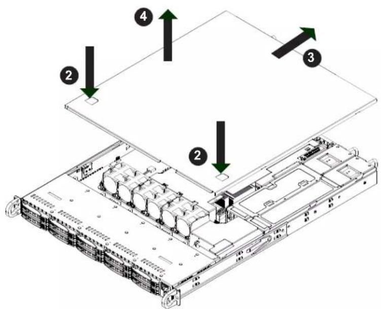
Removing the Top Cover
- Begin by removing power from the system as described in Section 3.1.
- Grasp the two handles on either side and pull the unit straight out until it locks (you will hear a "click").
- Depress the two buttons on the top of the chassis to release the top cover and at the same time, push the cover away from you until it stops.
- Lift the top cover from the chassis to gain full access to the inside of the server.
Warning: Except for short periods of time, do not operate the server without the cover in place. The chassis cover must be in place to allow for proper airflow and to prevent overheating.
text_image
Technical diagram of a server rack with labeled components and directional arrows indicating assembly or movement.Figure 3-1. Removing the Chassis Cover
Note: Graphics in this manual are for illustration purposes only. Your components may look slightly different.
3.3 Processor and Heatsink Installation
The processor (CPU) and processor carrier should be assembled together first to form the processor carrier assembly. This will be attached to the heatsink to form the processor heatsink module (PHM) before being installed onto the CPU socket.
Notes:
- Use ESD protection.
- Unplug the AC power cord from all power supplies.
- Check that the plastic protective cover is on the CPU socket and that none of the socket pins are bent. If they are, contact your retailer.
- When handling the processor, avoid touching or placing direct pressure on the land grid array (gold contacts).
- Improper installation or socket misalignment can cause serious damage to the processor or the socket and may require manufacturer repairs.
• Thermal grease is pre-applied on new heatsinks. No additional thermal grease is needed.
• Refer to the Supermicro website for updates on processor support. - Graphics in this manual are for illustration only. Your components may look different.
The Processor Carrier Assembly
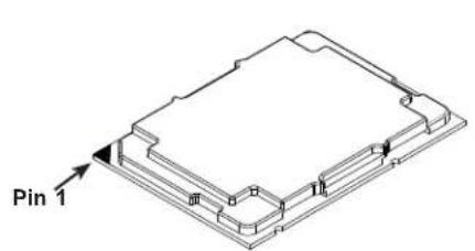
The processor carrier assembly is comprised of the processor and the processor carrier.
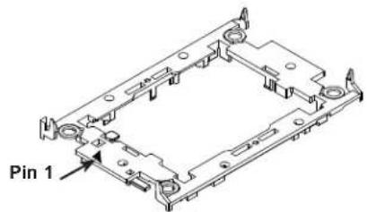
- Hold the processor with the land grid array (LGA, gold contacts) facing down. Locate the gold triangle at the corner of the processor and the corresponding hollowed triangle on the processor carrier as shown below. These triangles indicate the location of pin 1.
text_image
Pin 1Processor
text_image
Pin 1Carrier
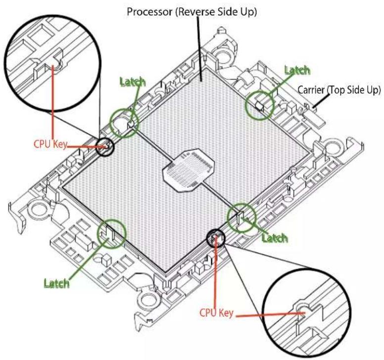
- Turn the processor over (with the gold LGA up). Locate the CPU keys on the processor and the four latches on the carrier as shown below.
text_image
Processor (Reverse Side Up) Latch Carrier (Top Side Up) CPU Key Latch Latch Latch CPU Key- Locate the lever on the carrier and, if necessary, press it down as shown below.
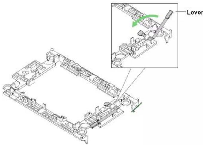
text_image
Lever- Align the CPU keys on the processor (A & B) with those on the carrier (a & b) as shown below.
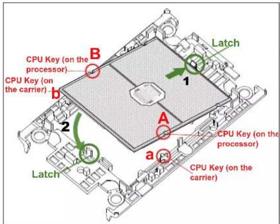
text_image
CPU Key (on the processor) CPU Key (on the carrier) Latch B 1 A 2 a Latch CPU Key (on the processor) CPU Key (on the carrier)- Carefully place one end of the processor under latch 1 on the carrier, and then press the other end down until it snaps into latch 2 and is properly seated on the carrier.
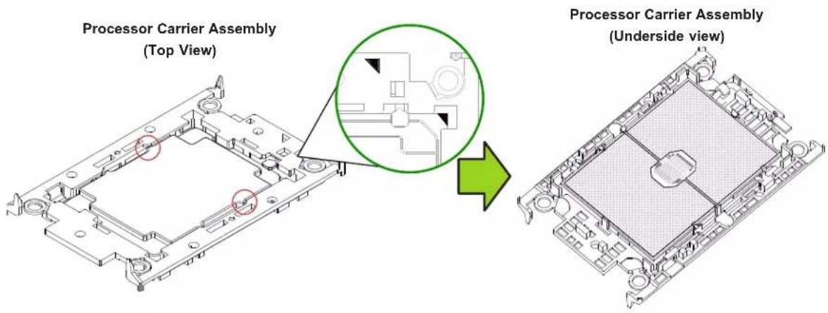
text_image
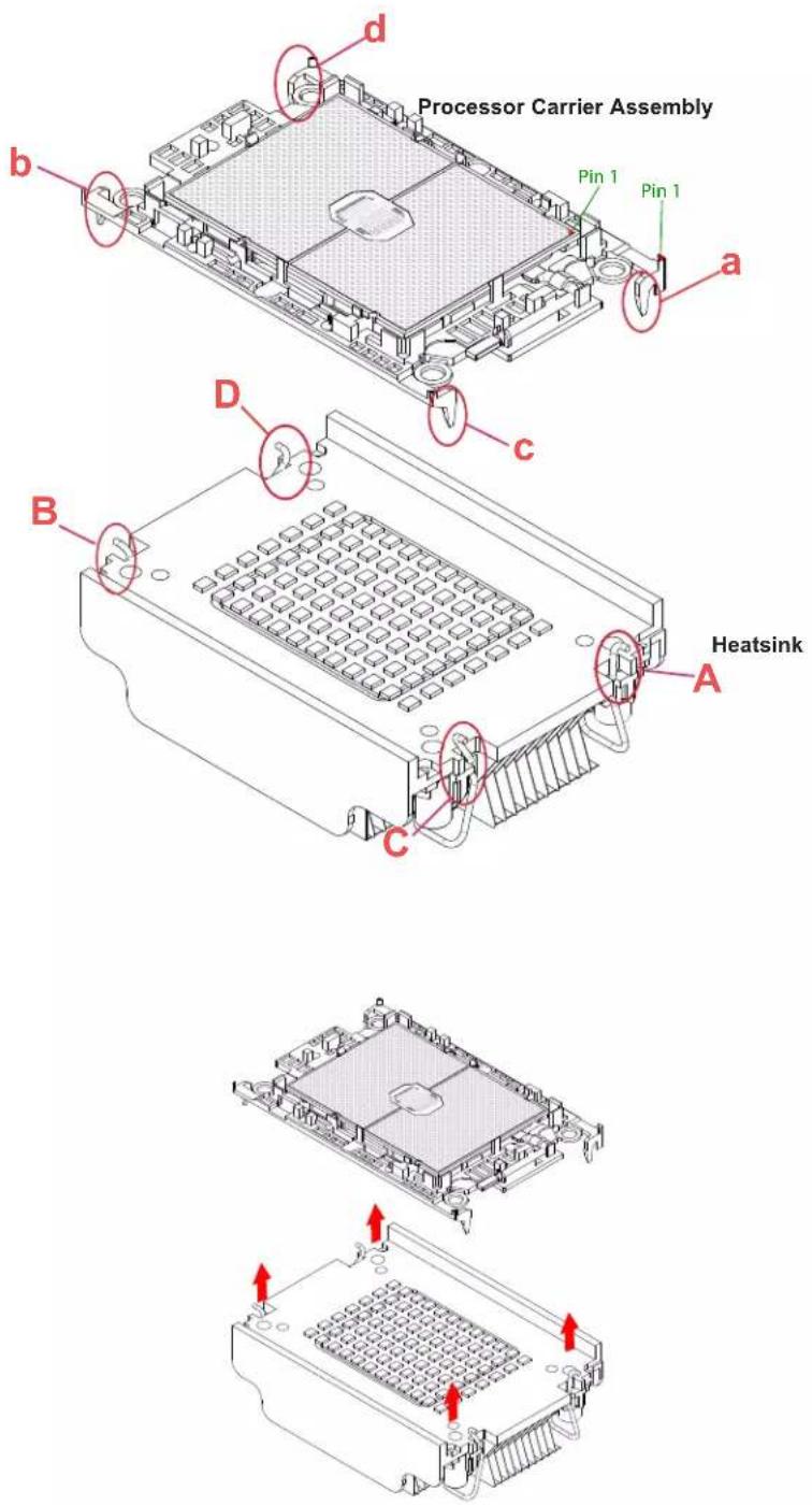
Processor Carrier Assembly (Top View) Processor Carrier Assembly (Underside view)The Processor Heatsink Module (PHM)
After creating the processor carrier assembly, mount the heatsink onto the carrier assembly to form the processor heatsink module (PHM).
Note: If this is a new heatsink, the thermal grease has been pre-applied. Otherwise, apply the proper amount of thermal grease to the underside of the heatsink.
-
Turn the heatsink over with the thermal grease facing up. Note the two triangle cutouts (A, B) located at the diagonal corners of the heatsink as shown in the drawing below.
-
On the processor carrier assembly, find pin 1, as noted by the triangles. Hold the processor carrier assembly over so that the gold LGA is facing up.
-
Align clip "a" (pin 1) on the carrier assembly with the triangular cutout A on the heatsink and b, c, d on the carrier assembly with B, C, D on the heatsink.
-
Push the carrier assembly onto the heatsink, making sure that all four clips on each corner are properly secured.

text_image
Processor Carrier Assembly Pin1 a b c D B A C HeatsinkInstalling the PHM into the CPU Socket
- Remove the plastic protective cover from the CPU socket. Gently squeeze the grip tabs then pull the cover off.

text_image
CPU Socket with Plastic Protective Cover Grip Tabs- Locate four threaded fasteners (a, b, c, d) on the CPU socket.

text_image
CPU Socket Threaded Fastener (a, b, c, d: Threaded Fasteners) CPU Socket Pin1- Locate four PEEK nuts (A, B, C, D) and four rotating wires (1, 2, 3, 4) on the heatsink as shown below.

text_image
A, B, C, D: Peek Nut 1, 2, 3, 4: Rotating Wire a, b, c, d: Threaded Fastener Heatsink Rotating Wire 2 B D Rotating Wire 4 Rotating Wire 3 Rotating Wire 1 Peek Nut CPU Socket Rotating Wire Peek Nut (Unlatched) (latched)- Check that the rotating wires (1, 2, 3, 4) are in the unlatched position as shown.

text_image
Unlatched State Rotating Wire Side View Top View Peek Nut-
Align nut A (next to the triangles and pin 1) on the heatsink with threaded fastener "a" on the CPU socket. Also align nuts B, C, D on the heatsink with threaded fasteners b, c, d on the CPU socket.
-
Gently place the heatsink on the CPU socket, making sure that each nut is properly aligned with its corresponding threaded fastener.

text_image
A, B, C, D: Peek Nut on the Heatsink B D C A b c a, b, c, d: Threaded Fastener on the CPU socket- Press all four rotating wires outward to latch the PHM onto the CPU socket.
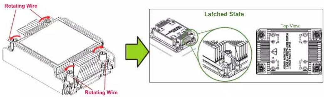
text_image
Rotating Wire Rotating Wire Latched State Top View- With a t30-bit screwdriver, tighten all PEEK nuts in the sequence of A, B, C, and D with even pressure not greater than 12 lbf-in.

text_image
Technical diagram showing a mechanical assembly with labeled components (A, B, C, D) and a green arrow indicating transformation or assembly.Removing the PHM from the CPU Socket
Be sure the system is shut down and all AC power cords are unplugged.
- Use a t30-bit screwdriver to loosen the four PEEK nuts on the heatsink in the sequence of A, B, C, and D.

text_image
B D Peek Nut C- Press the four rotating wires inward to unlatch the PHM as shown below.

text_image
Unlatched State Rotating Wire Side View Peek Nut- Gently lift the PHM upward to remove it from the CPU socket.

natural_image
Technical line drawing of a mechanical housing with mounting holes and internal components, showing two views with red arrows indicating movement (no text or symbols present)Removing the Processor Carrier Assembly from the PHM
Detach the four plastic clips (a, b, c, d) on the processor carrier assembly from the four corners of the heatsink (A, B, C, D) as shown below, and lift off the processor carrier assembly.
text_image
Processor Carrier Assembly Pin 1 Pin 1 a b c D Heatsink A B CRemoving the Processor from the Carrier Assembly
Unlock the lever from its locked position and push it upwards to disengage the processor from the carrier as shown below right. Carefully remove the processor from the carrier.
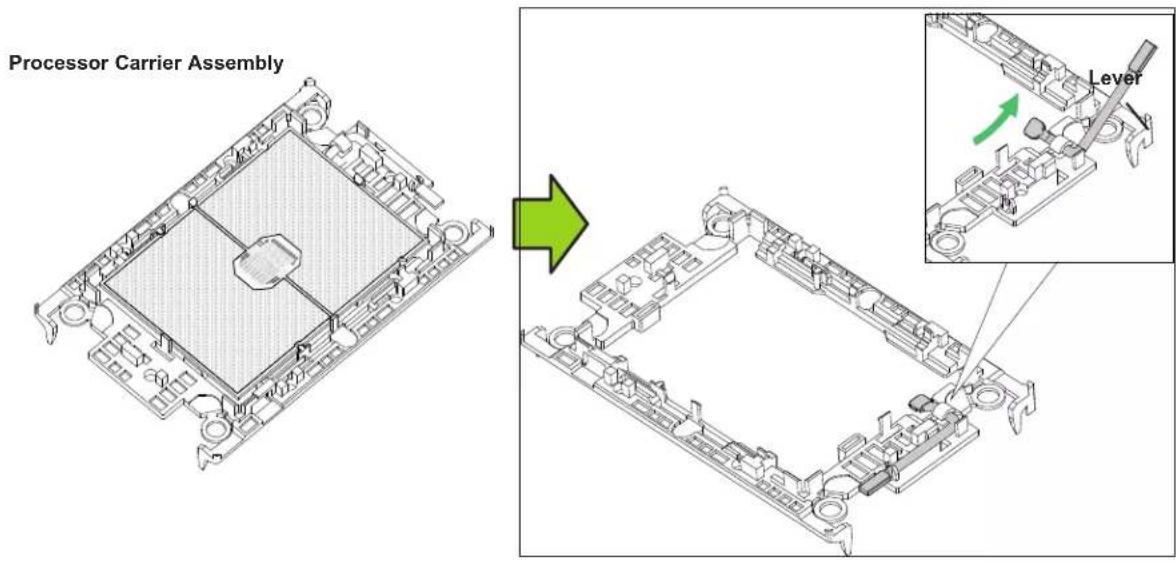
text_image
Processor Carrier Assembly LeverNote: Handle the processor with care to avoid damage.

natural_image
Isometric technical diagram of a mechanical assembly with no visible text or symbols3.4 Memory
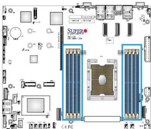
The X12SPO-NTF supports up to 2048 GB of ECC RDIMM/LRDIMM/RDIMM 3DS/LRDIMM 3DS with speeds of up to 3200 MHz in eight slots. Refer to the tables below for the recommended DIMM population order and additional memory information.
| 1 CPU, 8-DIMM Slots | |
| Number of DIMMs Memory | Population Sequence |
| 1 DIMMA1 | |
| 2 DIMMA1 / DIMME1 | |
| 3(Unbalanced: Not Recommended) | DIMMA1 / DIMME1 / DIMMC1 |
| 4 DIMMA1 / DIMME1 | / DIMMC1 / DIMMG1 |
| 5(Unbalanced: Not Recommended) | DIMMA1 / DIMME1 / DIMMC1 / DIMMG1 / DIMMB1 |
| 6 DIMMA1 / DIMME1 | / DIMMC1 / DIMMG1 / DIMMB1 / DIMMF1 |
| 7(Unbalanced: Not Recommended) | DIMMA1 / DIMME1 / DIMMC1 / DIMMG1 / DIMMB1 / DIMMF1 / DIMMD1 |
| 8 DIMMA1 / DIMME1 | / DIMMC1 / DIMMG1 / DIMMB1 / DIMMF1 / DIMMD1 / DIMMH1 |
Note: A/E/C/G channels must be populated with the same total capacity per channel if populated.
B/F/D/H channels must be populated with the same total capacity if populated.
| Type | Ranks Per DIMM and Data Width | Dimm Capacity (GB) | Speed (MT/s); Voltage (V); Slot Per Channel (SPC) and DIMM Per Channel (DPC)*Data below assumes 2 SPC unless otherwise noted. | ||
| 1DPC 2DPC | |||||
| 8 Gb 16 Gb | 1.2V 1.2V | ||||
| RDIMM | SRx8 8 GB | 16 GB | 3200 | 2933 PTH3200 SMT | |
| SRx4 16 GB | 32 GB | ||||
| DRx8 16 GB | 32 GB | ||||
| DRx4 32GB | 64 GB | ||||
| RDIMM-3DS | (4R/8R) x4 | 2H-64F GB4H-128 GB | 2H-128 GB4H 256 GB | 2933 PTH3200 PTH for 1 (SPC config only)3200 SMT | 2933 PTH3200 SMT |
| LRDIMM | QRx4 | 64 GB | 128 GB | 3200 | 3200 |
| LRDIMM-3DS | (4R/8R) X4 | 4H-128 GB | 2H-128 GB4H-256 GB | 3200 | 3200 |
General Guidelines for Optimizing Memory Performance
• Always use DDR4 memory of the same type, size and speed.
- Mixed DIMM speeds can be installed. However, all DIMMs will run at the speed of the slowest DIMM.
- The motherboard supports odd-numbered modules (one or three modules installed). However, to achieve the best memory performance, a balanced memory population is recommended.

text_image
SUPER X12SPO-NTF-/F REV: 2.0 DESIGNED IN USA DIMMF1 DIMME1 DIMMH1 DIMMG1 DIMMC1 DIMMD1 DIMMA1 DIMMB1DIMM Installation
- Insert the desired number of DIMMs into the memory slots based on the recommended DIMM population table at the beginning of this section (3.4 Memory).
- Push the release tabs outwards on both ends of the DIMM slot to unlock it.
- Align the key of the DIMM module with the receptive point on the memory slot.
- Align the notches on both ends of the module against the receptive points on the ends of the slot.
- Push both ends of the module straight down into the slot until the module snaps into place.
- Press the release tabs to the lock positions to secure the DIMM module into the slot.
DIMM Removal
Press both release tabs on the ends of the DIMM module to unlock it. Once the DIMM module is loosened, remove it from the memory slot.
text_image
SUPER X-250P-4170 F X-250P-4170 F CE FC
natural_image
Technical illustration of a mechanical assembly with a cylindrical component and a blue circular arrow indicating a feature (no text or symbols present)
text_image
Notches Release Tabs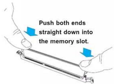
text_image
Push both ends straight down into the memory slot.3.5 Motherboard Battery
The motherboard uses non-volatile memory to retain system information when system power is removed. This memory is powered by a lithium battery residing on the motherboard.
Replacing the Battery
Begin by removing the top cover.
- Push aside the small clamp that covers the edge of the battery. When the battery is released, lift it out of the holder.
- To insert a new battery, slide one edge under the lip of the holder with the positive (+) side facing up. Then push the other side down until the clamp snaps over it.
Note: Handle used batteries carefully. Do not damage the battery in any way; a damaged battery may release hazardous materials into the environment. Do not discard a used battery in the garbage or a public landfill. Please comply with the regulations set up by your local hazardous waste management agency to dispose of your used battery properly.
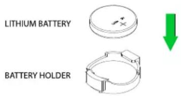
text_image
LITHIUM BATTERY BATTERY HOLDERFigure 3-2. Installing the Onboard Battery
Warning: There is a danger of explosion if the onboard battery is installed upside down (which reverses its polarities). This battery must be replaced only with the same or an equivalent type recommended by the manufacturer (CR2032).
3.6 Storage Drives
NVMe Drives
Your server may or may not have come with hard drives installed. Up to ten 2.5" NVMe drives are supported by the chassis.
The NVMe drives are mounted in drive carriers to simplify their installation and removal from the chassis. (Both procedures may be done without removing power from the system.)
NVMe Drive Carrier Indicators
Each drive carrier has two LED indicators: an activity indicator and a status indicator. For RAID configurations using a controller, the meaning of the status indicator is described in the table below. For OS RAID or non-RAID configurations, some LED indications are not supported, such as hot spare.
| Drive Carrier LED Indicator | |||
| Color Blinking Pattern Behavior for Device | |||
| Activity LED | Blue Solid On | SAS/NVMe drive installed | |
| Blue Blinking | I/O activity | ||
| Status LED | Red Solid On | Failure of drive with RSTe support | |
| Red Blinking | at 1 Hz Rebuild drive with RSTe support | ||
| Red | Blinking with two blinks and one stop at 1 Hz | Hot spare for drive with RSTe support (not supported in VMD mode) | |
| Red Blinking | at 4 Hz Identify drive with RSTe support | ||
| Green Solid On | Safe to remove NVMe device (not supported in VMD mode) | ||
| Amber Blinking | at 1 Hz | Attention state—do not remove NVMe device (not supported in VMD mode) | |
Removing a Hot-Swap Drive Carrier
- Push the release button on the drive carrier. This releases and extends the drive carrier handle. Use the handle to pull the carrier out of the chassis as shown below.
Caution: Except for short periods of time (swapping drives), do not operate the server with the drive carriers removed from the bays, regardless of how many drives are installed, for proper airflow.

text_image
Technical diagram showing server rack and internal components with numbered annotations indicating assembly steps.Figure 3-3. Removing a Drive Carrier
Note: Enterprise level NVMe drives are recommended for use in Supermicro chassis and servers. For information on recommended NVMe SSDs for SSG-110P-NTR10/NTR10-EU, visit the Supermicro website at https://www.supermicro.com/en/products/system/Storage/1U/SSG-110P-NTR10.
Installing a 2.5" NVMe Drive
- Place the NVMe drive carrier on a flat surface.
- Open the latch on the side of the drive carrier.
- Orient the drive with the connector facing the bottom rear of the carrier.
- From above, place the drive into the carrier while aligning the drive with the notches.
- Close the latches to secure the drive to the drive carrier.
- Use the open handle of the drive carrier to insert the carrier into the open drive bay.
- Secure the drive carrier into the drive bay by closing the drive carrier handle.
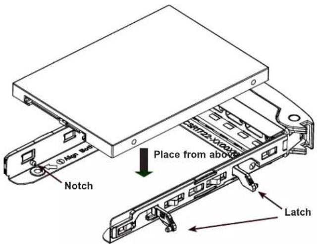
text_image
① Atp Bot Notch Place from above S1722-X100X LatchFigure 3-4. Installing Drive to Drive Carrier
Removing a 2.5" NVMe Drive
- After removing the carrier from the system, open the latches and push up from the bottom of the drive to remove it from the carrier.
- Replace with a new drive and insert the carrier back into the open drive bay.
Installing an M.2 Solid State Drive
Note: There are some thermal limitations with M.2 drives. Please contact Supermicro Support before installing an M.2 device.
The motherboard can accommodate two M.2 solid state drives (SSD). The M.2 socket supports NVMe PCIe 3.0 x4 (64 Gb/s) or SATA SSD cards in the 2280 or 22110 form factors. The 22110 form factor is recommended because the appropriate standoff comes pre-installed on the motherboard.
Caution: Use industry-standard anti-static equipment, such as gloves or wrist strap, and follow precautions to avoid damage caused by ESD.
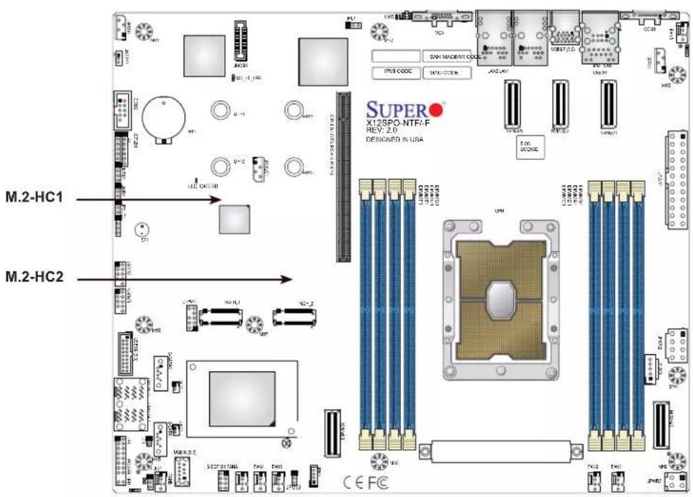
text_image
M.2-HC1 M.2-HC2 SUPER X12SPO-NTF-F REV: 2.0 DESIGNED IN USA CE FCFigure 3-5. M.2 Slot Locations
Installing an M.2 Device
- Power down the system as described in Section 3.1 and then remove the top chassis cover as described in Section 3.2.
- To loosen the M.2 plastic standoff on the motherboard, lift up its top square latch, and use gentle force to pull it out of the hole.
- Move and place the standoff plug in the proper hole.
- Insert the M.2 device at a slight angle in the M.2 slot, and ensure the notch on the other end of the device aligns the standoff top.
- Pull the top square latch down and ensure the latch plug is pushed in standoff to secure the device in place.
- Replace the node into the chassis.
Hot-Swap for NVMe Drives
Supermicro servers support NVMe surprise hot-swap. For even better data security, NVMe orderly hot-swap is recommended. NVMe drives can be ejected and replaced remotely using BMC.
Note: If you are using VROC, see Chapter 6 in this manual instead.
Ejecting a Drive
- BMC > System > Storage Monitoring > Physical View
- Select Device, Group and Slot, and click Eject. After ejecting, the drive Status LED indicator turns green.
- Remove the drive.
Note that Device and Group are categorized by the CPLD design architecture. The SSG-110P-NTR10/NTR10-EU server has one Device and one Group.
Slot is the slot number on which the NVMe drives are mounted.

text_image
Overview Physical View Logical View Controller Physical View ✓ Blink ✓ Unblink ✓ Opt ✓ Insert Staff LED Status Supported Actions Disk Inbit Capacity Link Speed Connected Logical Drive Connected Controller 0.0 0.1 SAMSUNG MCQLW999/MUP-0003 N/A 8.6 GTb-N/A N/A MiMe Devices(S) SAMSUNG MCQLW999/MUP-0003 N/A 8.6 GTb-N/A N/A MiMe Devices(S)Figure 3-6. BMC Screenshot
Replacing the Drive
- Insert the replacement drive.
- BMC > System > Storage Monitoring > Physical View
- Select Device, Group and slot and click Insert. The drive Status LED indicator flashes amber, then turns off. The Activity LED turns blue.
Checking the Temperature of an NVMe Drive
There are two ways to check using BMC.
Checking a Drive
- BMC > Server Health > NVMe SSD – Shows the temperatures of all NVMe drives.
- BMC > Server Health > Sensor Reading > NVME_SSD – Shows the single highest temperature among all the NVMe drives.
PCI Expansion Card Installation
The system includes one pre-installed riser card (RSC-S-6G4) which supports one FHHL PCIe x16. Riser cards position the expansion cards at a 90 degree angle, allowing them to fit inside the 1U chassis.
Installing PCI Expansion Cards
The riser cards have already been pre-installed into the motherboard. Perform the following steps to install an add-on card:

text_image
Riser Card BracketFigure 3-7. Removing the Riser Bracket
- Remove the riser card bracket from the chassis by unscrewing the screw indicated in the figure below.
- Lift the riser card bracket from the chassis.
- Install the riser card on the bracket with the two screws provided, see Figure 3-7.
- Remove the expansion slot shield on the chassis.
- Install the expansion card by sliding the card into the appropriate slot in the riser card.
- Install the entire assembly into the appropriate slot on the serverboard while aligning the bracket in the rear of the chassis.
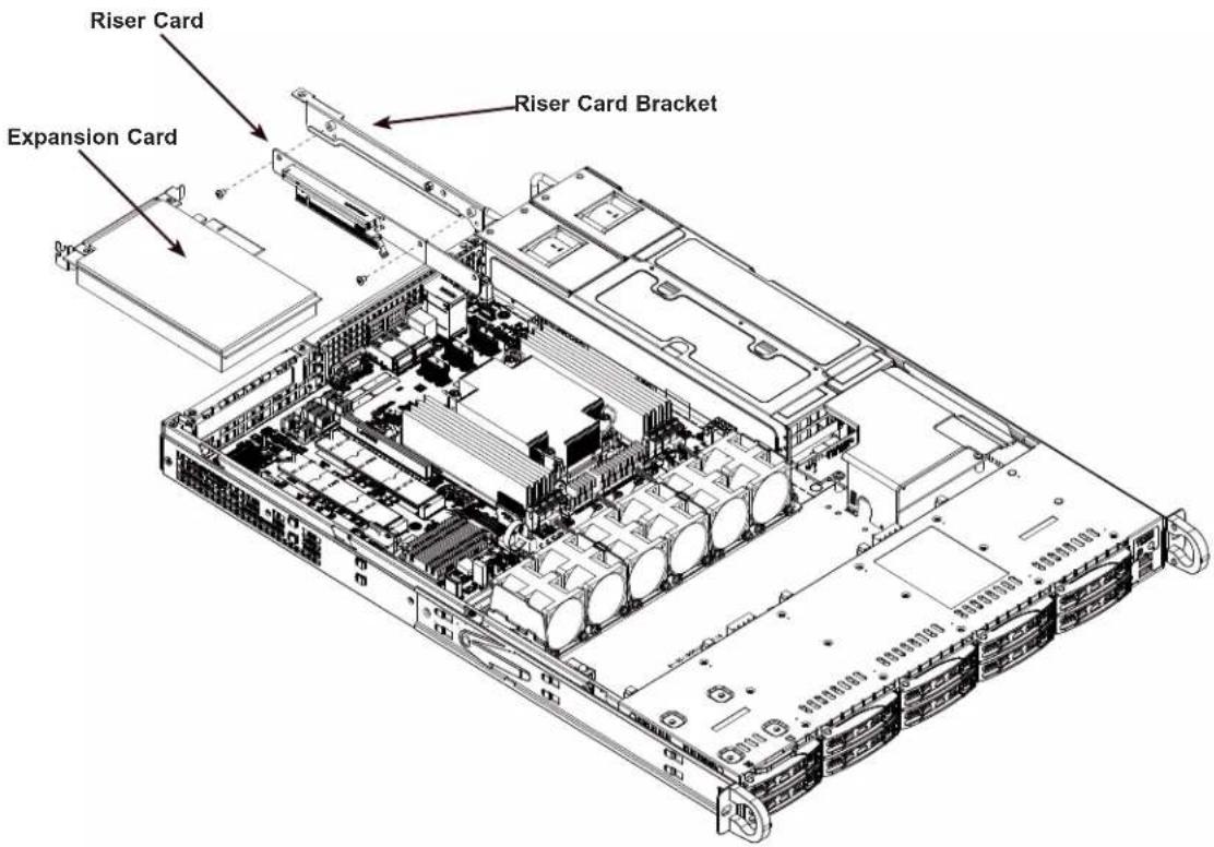
text_image
Riser Card Expansion Card Riser Card BracketFigure 3-8. Installing Riser Card to Bracket
Note: Graphics in this manual are for illustration purposes only. Your components may look slightly different.

natural_image
Back panel of a server rack with ports, connectors, and memory modules (no visible text or labels)Figure 3-9. PCI Expansion Card Chassis Slots
| Expansion Card Configurations | ||
| Slot Mechanical | Electrical | |
| 1 | Full height, half length x16 | |
CPU1
3.7 System Cooling
Six 4-cm counter-rotating fans provide the cooling for the system. Note that these fans are not hot-plug, and so must be replaced when they fail.
It is very important that the chassis top cover is installed for the cooling air to circulate properly through the chassis and cool the components.
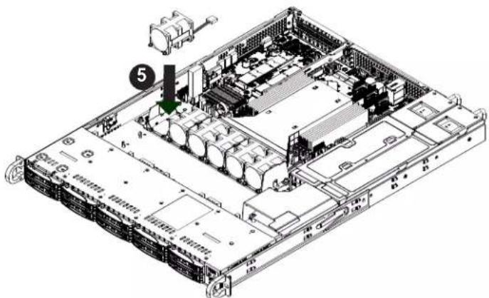
Changing a System Fan
-
If necessary, open the chassis while the system is running to determine which fan has failed. Never run the server for an extended period of time with the chassis cover open.
-
Remove power from the system as described in Section 3.1
-
Unplug the fan cable from the motherboard and remove the failed fan from the chassis.
-
Replace the failed fan with an identical 4-cm fan, available from Supermicro.
-
Push the new fan into the vacant space in the housing while making sure the arrows on the top of the fan (indicating air direction) point in the same direction as the arrows on the other fans.
-
Reposition the fan housing back over the two mounting posts in the system, then reconnect the fan wires to the same fan headers on the motherboard.
-
Power up the system and check that the fan is working properly and that the LED on the control panel has turned off. Finish by replacing the chassis cover.
natural_image
Isometric view of a server rack with internal components and a numbered component (no text or symbols visible)Note: Graphics in this manual are for illustration purposes only. Your components may look slightly different.
Figure 3-10. Changing a System Fan
Air Shroud
Air shrouds concentrate airflow to maximize fan efficiency. The CSE-116TS chassis air shroud does not require screws to set up.
Air Shroud Installation
- Begin by removing power from the system as described in Section 3.1. Remove the chassis cover as described in Section 3.2.
- Position the air shroud in alignment with the CPU, memory card and fan locations.
- Check the air shroud and serverboard components, removing the break-away pieces from the side of the air shroud if required.
- Place the air shroud into the chassis.

natural_image
Technical line drawing of a server rack with internal components and ventilation ducts (no text or labels)Figure 3-11. Installing the Air Shroud
Note: Graphics in this manual are for illustration purposes only. Your components may look slightly different.
Checking the Airflow
Check the Airflow
- Make sure there are no objects obstructing the airflow in and out of the server.
- Do not operate the server without hard drives or drive carriers in the drive bays. Use only recommended server parts.
- Make sure no wires or foreign objects obstruct airflow through the chassis. Pull all excess cabling out of the airflow path or use shorter cables.
- The control panel LEDs inform you of system status. See the Control Panel in Section 1.2 for details on the LEDs and the control panel buttons.
3.8 Power Supply
The SSG-110P-NTR10/NTR10-EU has a redundant, hot-plug 860 W power supply consisting of two power modules. Each power supply module has an auto-switching capability, which enables it to automatically sense and operate at a 100 V - 240 V input voltage.
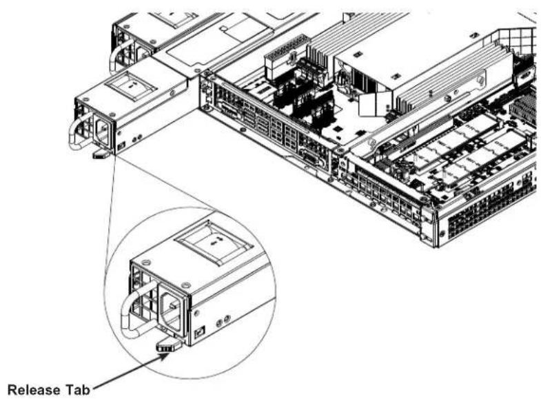
Power Supply Failure
If either of the two power supply modules fail, the other module will take the full load and allow the system to continue operation without interruption. The PWR Fail LED will illuminate and remain on until the failed unit has been replaced. Replacement units can be ordered directly from Supermicro (see contact information in the Preface). The hot-swap capability of the power supply modules allows you to replace the failed module without powering down the system.
Replacing the Power Supply
- Check the LEDs on the power supplies to determine which module has failed.
- Unplug the power cord from the failed module.
- Push the release tab (on the back of the power supply) as illustrated, then pull the power supply out using the handle provided.
- Push the new power supply module into the power bay until you hear a click (replace with the same model: p/n PWS-860P-1R2).
- Reconnect the power cord to the new module.
text_image
Release TabFigure 3-12. Replacing the Power Supply
Note: The figures above is intended to show the power supply locations only. The chassis and serverboard may differ from that found in the SSG-110P-NTR10/NTR10-EU.
3.9 Cable Routing Diagram
Refer to the diagram below for a representation of how the storage cables are routed through the node. When disconnecting cables to add or replace components, refer to this diagram so you can reroute them in the same manner.
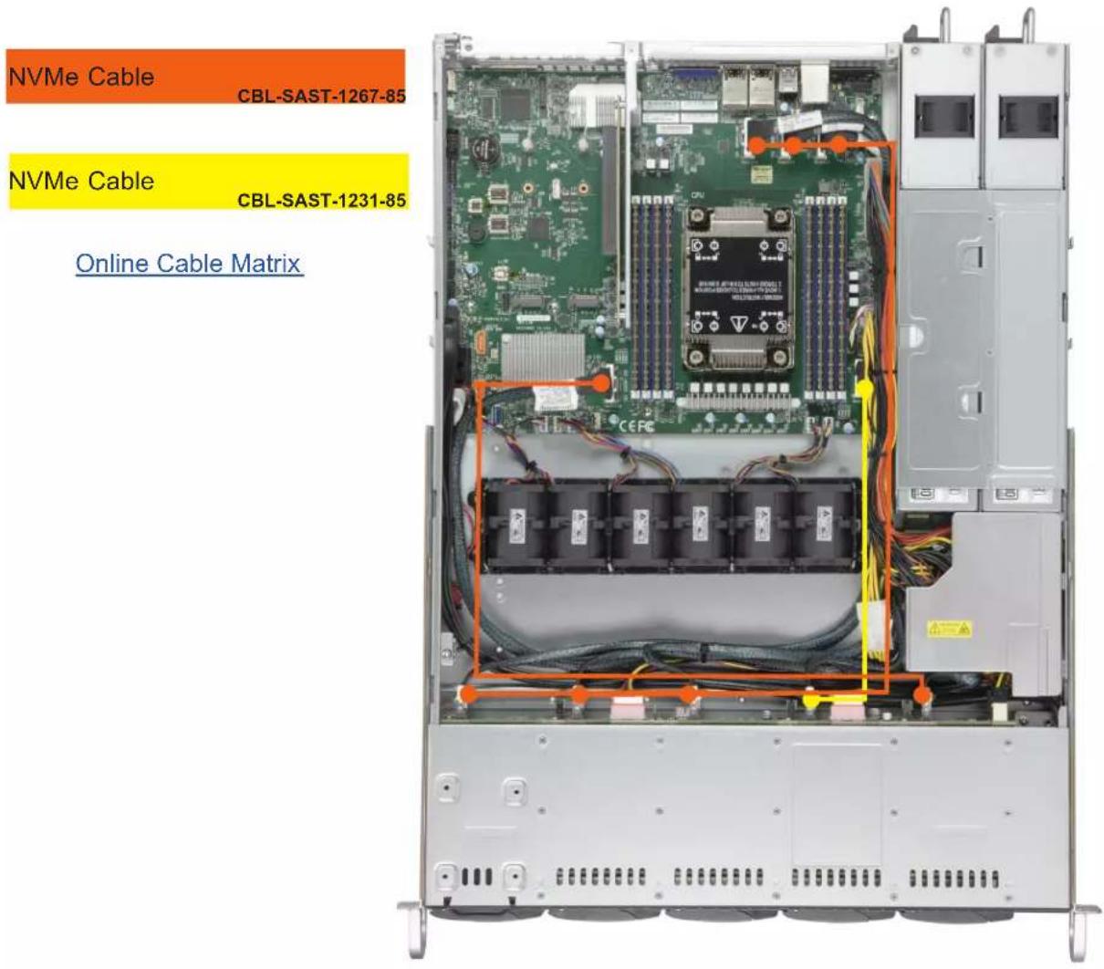
text_image
NVMe Cable CBL-SAST-1267-85 NVMe Cable CBL-SAST-1231-85 Online Cable MatrixFigure 3-13. Cable Routing Diagram
3.10 BMC Reset
The BMC can be reset using the UID button.
- Reset – Press and hold the button. After six seconds, the LED blinks at 2 Hz. The BMC resets and the reset duration is approximately 250 ms. Then the BMC starts to boot.
- Restore factory default configuration – Hold the button for twelve seconds. The LED blinks at 4 Hz while the defaults are configured. Note: All BMC settings including username and password will be removed except the FRU and network settings.
- Firmware update – When the BMC firmware is being updated, the UID LED blinks at 10 Hz.
| BMC Reset Options | ||
| Event UID LED | BMC Heartbeat LED | |
| Reset Blue, Blinks at 2 Hz Green, solid | ||
| Restore Defaults | Blue, Blinks at 4 Hz Off | |
| Update Blue, Blinks at 10 Hz | ||
Chapter 4
Motherboard Connections
This section describes the connections on the motherboard and provides pinout definitions.
Note that depending on how the system is configured, not all connections are required.
The LEDs on the motherboard are also described here. A motherboard layout indicating component locations may be found in Chapter 1. More detail can be found in the
Motherboard Manual.
Please review the Safety Precautions in Appendix A before installing or removing components.
4.1 Power Connections
24-pin Power Supply Connector
The 24-pin power supply connector (JPWR1) is power input for the CPU that must be connected to the power supply. You must also connect the 8-pin (JPWR2) and 4-pin (JPWR3) processor power connector to the power supply.
| ATX Power 24-pin Connector Pin Definitions | ||
| Pin# Definition Pin# Definition | ||
| 13 +3.3 V 1 +3.3 V | ||
| 14 -12 V 2 +3.3 V | ||
| 15 Ground 3 Ground | ||
| 16 PS_ON 4 +5 V | ||
| 17 Ground 5 Ground | ||
| 18 Ground 6 +5 V | ||
| 19 Ground 7 Ground | ||
| 20 Res (NC) 8 PWR_OK | ||
| 21 +5 V 9 5VSB | ||
| 22 +5 V 10 +12 V | ||
| 23 +5 V 11 +12 V | ||
| 24 Ground 12 +3.3 V | ||
Required Connection
8-Pin Power Connector
JPWR2 is an 8-pin 12 V DC power input for the CPU that must be connected to the power supply. Refer to the table below for pin definitions..
| 8-pin PowerPin Definitions |
| Pin# Definition |
| 1 - 4 Ground |
| 5 - 8 P12V (12 V Power) |
Required Connection
4-Pin Power Connector
JPWR3 is an 4-pin 12 V DC power input for the CPU that must be connected to the power supply. Refer to the table below for pin definitions..
| 4-pin PowerPin Definitions |
| Pin# Definition |
| 1 - 2 Ground |
| 3 - 4 P12V (12 V Power) |
Required Connection
Important: To provide adequate power supply to the motherboard, be sure to connect the 24-pin ATX PWR, the 8-pin PWR, and 4-pin PWR connectors to the power supply. Failure to do so may void the manufacturer warranty on your power supply and motherboard.
4.2 Headers and Connectors
Fan Headers
There are seven 4-pin fan headers (FAN1 \~ FAN5, FANA \~ FANB) on the motherboard. All these 4-pin fan headers are backwards compatible with the traditional 3-pin fans. However, fan speed control is available for 4-pin fans only by the Thermal Management via the BMC 2.0 interface. Refer to the table below for pin definitions.
| Fan HeaderPin Definitions |
| Pin# Definition |
| 1 Ground (Black) |
| 2 5 A/-12 V (Red) |
| 3 Tachometer |
| 4 PWM_Control |
Disk-On-Module Power Connector
Two power connectors for SATA DOM (Disk-On-Module) devices are located at JSD1 and JSD2. Connect appropriate cables here to provide power support for your serial link DOM devices.
| DOM Power Pin Definitions | |
| Pin# Definition | |
| 1 5 V | |
| 2 Ground | |
| 3 Ground | |
SGPIO Headers
There is one Serial Link General Purpose Input/Output (S-SGPIO1) header located on the motherboard. S-SGPIO is for sSATA use. Refer to the table below for pin definitions.
| SGPIO HeaderPin Definitions | |
| Pin# Definition Pin# Definition | |
| 1 NC 2 NC | |
| 3 Ground 4 Data | |
| 5 Load 6 Ground | |
| 7 Clock 8 NC | |
NC = No Connection
TPM/Port 80 Header
A Trusted Platform Module (TPM)/Port 80 header is located at JTPM1 to provide TPM support and Port 80 connection. Use this header to enhance system performance and data security. Refer to the table below for pin definitions. Please go to the following link for more information on the TPM: http://www.supermicro.com/manuals/other/TPM.pdf.
| Trusted Platform Module Header Pin Definitions | |||
| Pin# Definition Pin# Definition | |||
| 1 +3.3 | V 2 SPI_CS# | ||
| 3 RESET# 4 SPI_MISO | |||
| 5 SPI_CLK 6 GND | |||
| 7 SPI_MOSI 8 NC | |||
| 9 +3.3 | V Stdby 10 SPI_IRQ# | ||
Standby Power Header
The Standby Power header is located at JSTBY1 on the motherboard. You must have a card with a Standby Power connector and a cable to use this feature. Refer to the table below for pin definitions.
| Standby Power Pin Definitions | |
| Pin# Definition | |
| 1 +5 V | Standby |
| 2 Ground | |
| 3 No Connection | |
Power LED/Speaker
JD1 is used to connect an extra speaker. By default, pins 3-4 are closed with a cap to enable the onboard buzzer at SP1. To use an external speaker, connect the speaker header to pins 1-4. Refer to the table below for pin definitions.
| Power LED/Speaker HeaderPin Definitions | |
| Pin# Signal | |
| 1 P5V | |
| 2 Key | |
| 3 R_SPKPIN_N | |
| 4 R_SPKPIN | |
Power SMB (I²C) Header
The Power System Management Bus (I ^2 C) connector (JPI ^2 C1) monitors the power supply, fan, and system temperatures. Refer to the table below for pin definitions.
| Power SMB HeaderPin Definitions | |
| Pin# | Definition |
| 1 | Clock |
| 2 | Data |
| 3 | PMBUS_Alert |
| 4 | Ground |
| 5 | +3.3V |
Chassis Intrusion
A Chassis Intrusion header is located at JL1 on the motherboard. Attach the appropriate cable from the chassis to inform you when the chassis is opened. Refer to the table below for pin definitions.
| Chassis Intrusion Pin Definitions | |
| Pin# Definition | |
| 1 | Intrusion Input |
| 2 | Ground |
NVMe I²C Header
Connector JNVI ^2 C1 is a management header for the Supermicro AOC NVMe PCIe peripheral cards. Connect the I ^2 C cable to this connector.
Note: When installing an NVMe device on the motherboard, connect the first NVMe port (JNVI ^2 C1) first for your system to work properly.
SATA Ports
Eight SATA 3.0 ports are located on the motherboard supported by the chipset. These SATA ports support RAID 0, 1, 5, and 10. In addition, there are also two S-SATA ports (S-SATA0, S-SATA1) that include SATA DOM power. SATA ports provide serial-link signal connections, which are faster than the connections of Parallel ATA.
Note: For more information on the SATA HostRAID configuration, please refer to the Intel SATA HostRAID user's guide posted on our website at https://www.supermicro.com/support/manuals/.
M.2 Slot
The motherboard has two M.2 slots. M.2 was formerly known as Next Generation Form Factor (NGFF) and serves to replace mini PCIe. M.2 allows for a variety of card sizes, increased functionality, and spatial efficiency. The M.2 sockets on the motherboard support PCIe 3.0 x4/SATA 3 SSD cards in the 2280 and 22110 form factors.
NC-SI Header for BMC Support
A Network-Controller Sideband Interface (NC-SI) header is located at JNCSI1 on the motherboard. For remote management, connect the appropriate cable from this header to an add-on card to provide the out-of-band (sideband) connection between the onboard Baseboard Management Controller (BMC) and a Network Interface Controller (NIC). For the network sideband interface to work properly, you will need to use a NIC add-on card that supports NC-SI and must use a special cable. Please contact Supermicro at www.supermicro.com to purchase the cable for this header. Refer to the table below for pin definitions.
| NC-SI HeaderPin Definitions | |||
| Pin# Definition Pin# Definition | |||
| 1 Clock 2 GND | |||
| 3 CRS_DV 4 GND | |||
| 5 RX_D0 6 GND | |||
| 7 RX_D1 8 GND | |||
| 9 TX_D0 10 GND | |||
| 11 | TX_D1 12 GND | ||
| 13 TX_EN 14 GND | |||
| 15 ARB_IN | 16 | ARB_OUT | |
| 17 Power | 18 | Power | |
| 19 Power | 20 | Power | |
| 21 Power | 22 | NC | |
Intel RAID Key Header
The JRK1 header allows the user to enable RAID functions for NVMe connections. Refer to the table below for pin definitions.
| Intel RAID Key Header Pin Definitions | |
| Pin# Definition | |
| 1 | GND |
| 2 | PU 3.3V Stdby |
| 3 | GND |
| 4 | PCH RAID KEY |
4-pin BMC External I²C Header
A System Management Bus header for BMC is located at JIPMB1. Connect a cable to this header to use the IPMB I²C connection on your system. See the table below for pin definitions.
| External I2C Header Pin Definitions | |
| Pin# Definition | |
| 1 Data | |
| 2 GND | |
| 3 | Clock |
| 4 | No Connection |
System Front Inlet Temperature Sensor Header
JSEN1 is the system front inlet temperature sensor header. It represents the ambient air temperature entering the system.
Control Panel
JF1 contains header pins for various buttons and indicators that are normally located on a control panel at the front of the chassis. These connectors are designed specifically for use with Supermicro chassis. See the figure below for the descriptions of the front control panel buttons and LED indicators.
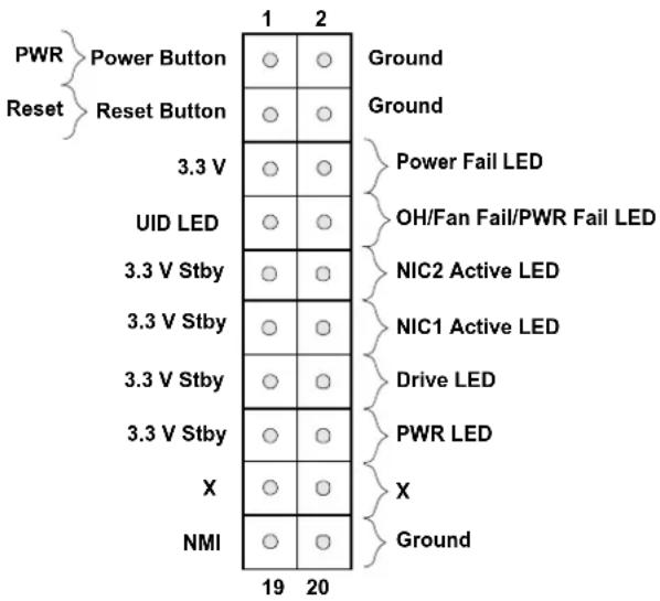
text_image
PWR Reset Power Button Reset Button 3.3 V UID LED 3.3 V Stby 3.3 V Stby 3.3 V Stby 3.3 V Stby X NMI 19 20 Ground Ground Power Fail LED OH/Fan Fail/PWR Fail LED NIC2 Active LED NIC1 Active LED Drive LED PWR LED X GroundFigure 4-1. JF1 Control Panel Pins
Power Button
The Power Button connection is located on pins 1 and 2 of JF1. Momentarily contacting both pins will power on/off the system. This button can also be configured to function as a suspend button (with a setting in the BIOS). To turn off the power when the system is in suspend mode, press the button for four seconds or longer. Refer to the table below for pin definitions.
| Power ButtonPin Definitions (JF1) | |
| Pin# Definition | |
| 1 Signal | |
| 2 Ground |
Reset Button
The Reset Button connection is located on pins 3 and 4 of JF1. Attach it to a hardware reset switch on the computer case to reset the system. Refer to the table below for pin definitions.
| Reset ButtonPin Definitions (JF1) |
| Pin# Definition |
| 3 Reset |
| 4 Ground |
Power Fail LED
The Power Fail LED connection is located on pins 5 and 6 of JF1. Refer to the table below for pin definitions.
| Power Fail LEDPin Definitions (JF1) | |
| Pin# Definition | |
| 5 3.3 V | |
| 6 PWR Supply Fail | |
Overheat (OH)/Fan Fail
Connect an LED cable to pins 7 and 8 of the Front Control Panel to use the Overheat/Fan Fail LED connections. The LED on pin 8 provides warnings of overheating or fan failure. Refer to the tables below for pin definitions.
| OH/Fan Fail Indicator Status | |
| State | Definition |
| Off Normal | |
| On Overheat | |
| Flashing Fan Fail | |
| OH/Fan Fail LEDPin Definitions (JF1) | |
| Pin# Definition | |
| 7 UID LED | |
| 8 OH/Far | Fail LED |
The NIC (Network Interface Controller) LED connection for LAN port 1 is located on pins 11 and 12 of JF1, and LAN port 2 is on pins 9 and 10. Attach the NIC LED cables here to display network activity. Refer to the table below for pin definitions.
| LAN1/LAN2 LEDPin Definitions (JF1) | |
| Pin# Definition | |
| 9/11 Vcc | |
| 10/12 | NIC2 Active LED/NIC1 Active LED |
Drive LED
The Drive LED connection is located on pins 13 and 14 of JF1. Attach a cable to pin 14 to show hard drive activity status. Refer to the table below for pin definitions.
| Drive LEDPin Definitions (JF1) |
| Pins Definition |
| 13 UID_SW |
| 14 Drive Active |
Power LED
The Power LED connection is located on pins 15 and 16 of JF1. Refer to the table below for pin definitions.
| Power LEDPin Definitions (JF1) | |
| Pins Definition | |
| 15 3.3 | V Stby |
| 16 PWR | LED |
NMI Button
The non-maskable interrupt (NMI) button header is located on pins 19 and 20 of JF1. Refer to the table below for pin definitions.
| NMI ButtonPin Definitions (JF1) |
| Pins Definition |
| 19 Control |
| 20 Ground |
4.3 Input/Output Ports
See the figure below for the locations and descriptions of the I/O ports on the rear of the motherboard.
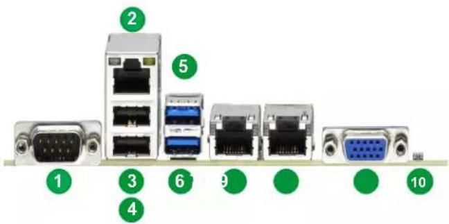
text_image
1 2 3 4 5 6 7 8 9 10Figure 4-2. I/O Port Locations and Definitions
| Rear I/O Ports | ||
| # Description # Description | ||
| 1 COM1 6 USB7 (3.2 Gen 1) | ||
| 2 BMC_LAN 7 LAN1 | ||
| 3 USB0 8 LAN2 | ||
| 4 USB1 9 VGA | ||
| 5 USB6 (3.2 Gen 1) 10 UID Switch / BMC Reset | ||
VGA Port
A video (VGA) port is located next to LAN2 on the I/O back panel. Refer to the board layout below for the location.
COM Ports
Two COM connections (COM1, COM2) are located on the motherboard.
| COM PortPin Definitions | |||
| Pin# Definition Pin# Definition | |||
| 1 | DCD | 6 | DSR |
| 2 | RXD | 7 | RTS |
| 3 | TXD | 8 | CTS |
| 4 | DTR | 9 | RI |
| 5 | Ground | 10 | N/A |
LAN Ports
Two Gigabit Ethernet ports, LAN1, LAN2, (-NTF: Two 10 Gigabit Ethernet ports; -F: Two Gigabit Ethernet ports) are located on the I/O back panel. In addition, a dedicated BMC LAN is located above the USB0/1 ports on the back panel. All of these ports accept RJ45 cables. Please refer to the LED Indicator section for LAN LED information.
| LAN PortPin Definition | ||
| Pin# Definition Pin# Definition | ||
| 1 TD0- 11 P3V3_Dual | ||
| 2 TD0+ 12 Act LED (Yellow) | ||
| 3 TD1- 13 | Link 1000(Amber) | |
| 4 TD1+ 14 | Link 100 LED(Green) | |
| 5 TD2- 15 GND | ||
| 6 TD2+ 16 GND | ||
| 7 TD3- 17 GND | ||
| 8 TD3+ 18 GND | ||
| 9 COMMCT | ||
| 10 GND | ||
| BMC LANPin Definition | |||
| Pin# Definition Pin# Definition | |||
| 9 | 19 GND | ||
| 10 TD0+ | 20 | Act LED(Yellow) | |
| 11 | TD0- | 21 | Link 100 LED(Green) |
| 12 TD1+ | 22 | Link 1000 LED(Amber) | |
| 13 TD1- | 23 SGND | ||
| 14 TD2+ | 24 SGND | ||
| 15 TD2- | 25 SGND | ||
| 16 TD3+ | 26 SGND | ||
| 17 TD3- | |||
| 18 GND | |||
Unit Identifier Switch (UID-SW)/BMC Reset: One button with two functions
A Unit Identifier (UID) switch and two LED Indicators are located on the motherboard. The UID switch, UID-SW, is located next to the VGA port on the back panel.
| Function | User Input | Behavior | LED Activity |
| UID LED Indicator | Push Once | Turns on the UID LED | UID LED turns solid blue |
| Push Again | Turns off the UID LED | UID LED turns off | |
| BMC Reset | Push and hold for 6 seconds | BMC will do a cold boot | BMC Hearbeat LED turns solid green |
| Push and hold for 12 seconds | BMC will reset to factory default | BMC Hearbeat LED turns solid green |
Note: After pushing and holding the UID-SW for 12 seconds, all BMC settings including username and password will revert back to the factory default. Only the network settings and FRU are retained.
| UID Switch Pin Definitions | |
| Pin# | Definition |
| 1 | Button In |
| 2 | Ground |
| G1 | Ground |
| G2 | Ground |
| UID LEDPin Definitions | |
| Color | Status |
| Blue: On Unit Identified | |
Universal Serial Bus (USB) Ports
There are two USB 2.0 ports (USB0/1) and two USB 3.2 Gen 1 ports (USB6/7) located on the I/O back panel. The motherboard also has two front access USB 2.0 headers (USB2/3 and USB4/5) and one front access USB 3.2 Gen 1 header (USB8/9). The USB10 header is USB 3.2 Gen 1 Type-A. The onboard headers can be used to provide front side USB access with a cable (not included).
| Back Panel USB 0/1 (2.0) Pin Definitions | |||
| Pin# Definition Pin# Definition | |||
| 1 | +5 V | 5 | +5 V |
| 2 | USB_N | 6 | USB_N |
| 3 | USB_P | 7 | USB_P |
| 4 | Ground | 8 | Ground |
| Front Panel USB 2/3, 4/5 (2.0) Pin Definitions | |||
| Pin# Definition | Pin# Definition | ||
| 1 | +5 V | 2 | +5 V |
| 3 | USB_N | 4 | USB_N |
| 5 | USB_P | 6 | USB_P |
| 7 | Ground | 8 | Ground |
| 9 | Key | 10 | NC |
| Back Panel USB 6/7 (3.2 Gen 1)Pin Definitions | |||
| Pin# Definition Pin# Definition | |||
| A1 VB | US B1 Power | ||
| A2 D- | B2 USB_N | ||
| A3 D+ | B3 USB_P | ||
| A4 GND | B4 GND | ||
| A5 Stda_SSRX- | B5 USB3_RN | ||
| A6 Stda_SSRX+ | B6 USB3_RP | ||
| A7 GND | B7 GND | ||
| A8 Stda_SSTX- | B8 USB3_TN | ||
| A9 Stda_SSTX+ | B9 USB3_TP | ||
| Front Panel USB 8/9 (3.2 Gen 1) Pin Definitions | |||
| Pin# Definition | Pin# Definition | ||
| 1 | VBUS | 19 Power | |
| 2 | Stda_SSRX- | 18 USB3_RN | |
| 3 | Stda_SSRX+ | 17 USB3_RP | |
| 4 | GND | 16 GND | |
| 5 | Stda_SSTX- | 15 USB3_TN | |
| 6 | Stda_SSTX+ | 14 USB3_TP | |
| 7 | GND | 13 GND | |
| 8 | D- | 12 USB_N | |
| 9 | D+ | 11 | USB_P |
| 10 | x | ||
| Type A USB 10 (3.2 Gen 1) Pin Definitions | |||
| Pin# Definition | Pin# Definition | ||
| 1 | VBUS | 5 | SSRX- |
| 2 | USB_N | 6 | SSRX+ |
| 3 | USB_P | 7 | GND |
| 4 | Ground | 8 | SSTX- |
| 9 | SSTX+ | ||
4.4 Jumpers
How Jumpers Work
To modify the operation of the motherboard, jumpers can be used to choose between optional settings. Jumpers create shorts between two pins to change the function of the connector. Pin 1 is identified with a square solder pad on the printed circuit board. Refer to the diagram below for an example of jumping pins 1 and 2. Refer to the motherboard layout page for jumper locations.
Note: On two-pin jumpers, "Closed" means the jumper is on, and "Open" means the jumper is off the pins.

flowchart
graph TD
    A["Connector Pins"] --> B["Top View"]
    B --> C["Connector Pins with a Jumper installed on Pins 1 and 2"]
CMOS Clear
JBT1 is used to clear CMOS, which will also clear any passwords. Instead of pins, this jumper consists of contact pads to prevent accidentally clearing the contents of CMOS.
To Clear CMOS

- First power down the system and unplug the power cord(s).
- Remove the cover of the chassis to access the motherboard and remove the battery from the motherboard.
- Short the CMOS pads with a metal object such as a small screwdriver for at least four seconds.
- Remove the screwdriver (or shorting device).
- Re-install the battery.
- Replace the cover, reconnect the power cord(s), and power on the system.
Note 1: Clearing CMOS will also clear all passwords.
Note 2: Do not use the PW_ON connector to clear CMOS.
Watchdog
Watchdog (JWD1) is a system monitor that can reboot the system when a software application hangs. Close pins 1-2 to reset the system if an application hangs. Close pins 2-3 to generate a non-maskable interrupt (NMI) signal for the application that hangs. Refer to the table below for jumper settings. The Watchdog must also be enabled in the BIOS.
| WatchdogJumper Settings | |
| Jumper Setting Definition | |
| Pins 1-2 Reset | |
| Pins 2-3 NMI | |
| Open Disabled | |
LAN Port Enable/Disable
Change the setting of jumpers JPL1 for LAN1/LAN2 to enable or disable the LAN ports. The default setting is Enabled.
| LAN Port Enable/DisableJumper Settings | |
| Jumper Setting Definition | |
| Pins 1-2 Enable | |
| Pins 2-3 Disable | |
ME Manufacturing Mode
Close the pins 2-3 of jumper JPME2 to bypass SPI flash security and for the system to operate in the manufacturing mode, which allows you to flash system firmware from a host server for system setting modifications. Refer to the table below for jumper settings. The default setting is normal.
| Manufacturing ModeJumper Settings | |
| Jumper Setting Definition | |
| Pins 1-2 Normal | |
| Pins 2-3 Manufacturing Mode | |
4.5 LED Indicators
LAN LEDs
Two LAN ports (LAN 1 and LAN 2) are located on the I/O back panel of the motherboard. Each Ethernet LAN port has two LEDs. The green LED indicates activity, while the other Link LED may be green, amber, or off to indicate the speed of the connection. Refer to the tables below for more information.
| LAN1/2 Activity LED (Right)LED State | ||
| Color Status Definition | ||
| Green Flashing Active | ||
| LAN1/2 Link LED (Left) (for -NTF only)LED State | |
| LED Color Definition | |
| Green 10Gbps | |
| Yellow/Amber 1Gbps | |
Unit ID LED
A rear UID LED indicator (LED2) is located near the UID switch on the I/O back panel. This UID indicator provides easy identification of a system unit that may need service.
| UID LEDLED Indicator | |
| LED Color Definition | |
| Blue: On Unit | Identified |
BMC LAN LEDs
In addition to LAN1 and LAN2, an BMC LAN is also located on the I/O back panel. The amber LED on the right indicates activity, while the green LED on the left indicates the speed of the connection. Refer to the table below for more information.
| BMC LAN LEDs | ||
| Color/State Definition | ||
| Link (left) | Green: Solid | 100Mbps |
| Amber: Solid | 1Gbps | |
| Activity (Right) | Amber: Blinking | Active |
BMC Heartbeat LED
A BMC Heartbeat LED is located at BMC_HB_LED on the motherboard. When the LED is blinking, the BMC is functioning normally. Refer to the table below for more information.
| BMC Heartbeat LED Indicator | |
| LED Color Definition | |
| Green:Blinking | BMC Normal |
Onboard Power LED
The Onboard Power LED is located at POWER_LED on the motherboard. When this LED is on, the system is on. Be sure to turn off the system and unplug the power cord before removing or installing components. Refer to the table below for more information.
| Onboard Power LED LED Indicator | |
| LED Color Definition | |
| Off | System Off (power cable no connected) |
| Green System | On |
CATERR LED
A CATERR LED is located at CATERR_LED. When this LED is orange, the system is experiencing a catastrophic error.
Chapter 5
Software
After the hardware has been installed, you can install the Operating System (OS), configure RAID settings and install the drivers.
5.1 Microsoft Windows OS Installation
If you will be using RAID, you must configure RAID settings before installing the Windows OS and the RAID driver. Refer to the RAID Configuration User Guides posted on our website at www.supermicro.com/support/manuals.
Installing the OS
- Create a method to access the MS Windows installation ISO file. That might be a flash or media drive, or the BMC KVM console.
- Retrieve the proper RST/RSTe driver. Go to the Supermicro web page for your motherboard and click on "Download the Latest Drivers and Utilities", select the proper driver, and copy it to a USB flash drive.
- Boot from a bootable device with Windows OS installation. You can see a bootable device list by pressing F11 during the system startup.

text_image
Please select boot device: ATEN Virtual CDROM YSOJ → IPMI virtual drive (Legacy) ASUS SDRW-08D2S-U F601 → USB DVD device (Legacy) USB FLASH DRIVE PMAP → USB flash drive with OS installation (Legacy) IBA 40-10G Slot 1900 v1060 → PXE boot (Legacy) UEFI: ATEN Virtual CDROM YSOJ → IPMI virtual drive (UEFI) UEFI: ASUS SDRW-08D2S-U F601 → USB DVD device (UEFI) UEFI: Built-in EFI Shell Enter Setup ↑ and ↓ to move selection ENTER to select boot device ESC to boot using defaultsFigure 5-1. Select Boot Device
- During Windows Setup, continue to the dialog where you select the drives on which to install Windows. If the disk you want to use is not listed, click on "Load driver" link at the bottom left corner.

text_image
Where do you want to install Windows? Name Total size Free space Type Refresh Delete Format New Load driver Extend We couldn't find any drives. To get a storage driver, click Load driver. NextFigure 5-2. Load Driver Link
To load the driver, browse the USB flash drive for the proper driver files.
- For RAID, choose the SATA/sSATA RAID driver indicated then choose the storage drive on which you want to install it.
-
For non-RAID, choose the SATA/sSATA AHCI driver indicated then choose the storage drive on which you want to install it.
-
Once all devices are specified, continue with the installation.
- After the Windows OS installation has completed, the system will automatically reboot multiple times.
5.2 Driver Installation
The Supermicro website contains drivers and utilities for your system at https://www.supermicro.com/wdl/driver. Some of these must be installed, such as the chipset driver.
After accessing the website, go into the CDR_Images (in the parent directory of the above link) and locate the ISO file for your motherboard. Download this file to a USB flash or media drive. (You may also use a utility to extract the ISO file if preferred.)
Another option is to go to the Supermicro website at http://www.supermicro.com/products/. Find the product page for your motherboard, and "Download the Latest Drivers and Utilities". Insert the flash drive or disk and the screenshot shown below should appear.
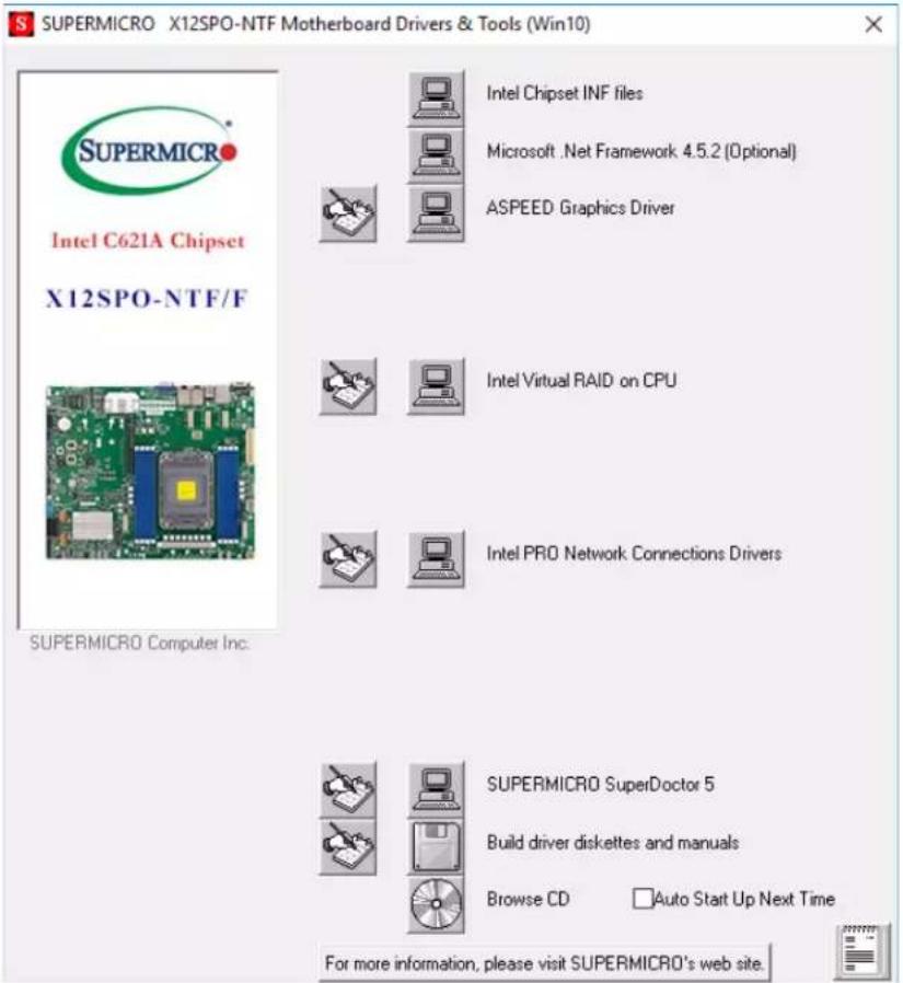
text_image
SUPERMICRO X12SPO-NTF Motherboard Drivers & Tools (Win10) Intel C621A Chipset X12SPO-NTF/F SUPERMICRO Computer Inc. Intel Chipset INF files Microsoft .Net Framework 4.5.2 (Optional) ASPEED Graphics Driver Intel Virtual RAID on CPU Intel PRO Network Connections Drivers SUPERMICRO SuperDoctor 5 Build driver diskettes and manuals Browse CD Auto Start Up Next Time For more information, please visit SUPERMICRO's web site.Figure 5-3. Driver & Tool Installation Screen
Note: Click the icons showing a hand writing on paper to view the readme files for each item. Click the computer icons to the right of these items to install each item (from top to the bottom) one at a time. After installing each item, you must re-boot the system before moving on to the next item on the list. The bottom icon with a CD on it allows you to view the entire contents.
5.3 SuperDoctor® 5
The Supermicro SuperDoctor 5 is a program that functions in a command-line or web-based interface for Windows and Linux operating systems. The program monitors such system health information as CPU temperature, system voltages, system power consumption, fan speed, and provides alerts via email or Simple Network Management Protocol (SNMP).
SuperDoctor 5 comes in local and remote management versions and can be used with Nagios to maximize your system monitoring needs. With SuperDoctor 5 Management Server (SSM Server), you can remotely control power on/off and reset chassis intrusion for multiple systems with SuperDoctor 5 or BMC. SuperDoctor 5 Management Server monitors HTTP, FTP, and SMTP services to optimize the efficiency of your operation.
SuperDoctor® Manual and Resources
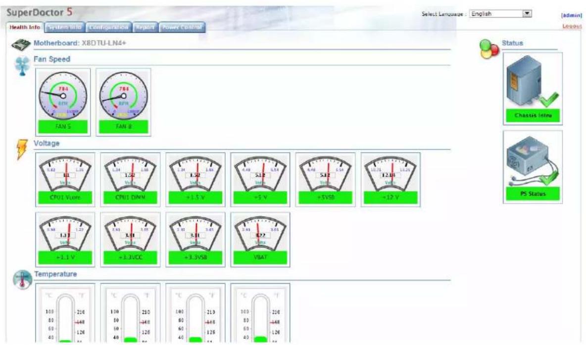
text_image
SuperDoctor 5 Health Info System info Configuration Report Power Control Select Language : English [admin] Layout Motherboard: X8DTU-LN4+ Fan Speed FAN S FAN B Voltage CPU1 Vcc CPU1 DIMM +1.5 V -5 V +5VSD +12 V +1.1 V +3.3VCC +3.3VSB VSAT Temperature °C T 100 -210 80 -448 60 -126 40 -40 °C T 100 -210 80 -448 60 -126 40 -40 °C T 100 -210 80 -448 60 -126 40 -40 °C T 100 -210 80 -448 60 -126 40 -40Figure 5-4. SuperDoctor 5 Interface Display Screen (Health Information)
5.4 BMC
The motherboard provides remote access, monitoring and management through the baseboard management controller (BMC) and other management controllers distributed among different system modules. There are several BIOS settings that are related to BMC.
For general documentation and information on BMC, visit our website at:
www.supermicro.com/en/solutions/management-software/bmc-resources
BMC ADMIN User Password
For security, each system is assigned a unique default BMC password for the ADMIN user. This can be found on a sticker on the motherboard or on the chassis. The sticker also displays the BMC MAC address.
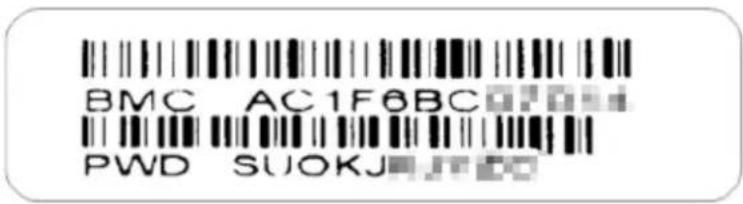
text_image
BMC AC1F6BC PWD SUOKJFigure 5-5. BMC Password Label
See Chapter 1 for label location.
Chapter 6
Optional Components
This chapter describes optional system components and installation procedures.
6.1 Optional Parts List
| Optional Parts List | ||
| Description Part Number Quantity | ||
| Inlet Thermal Sensor MCP-280-00033-0N 1 | ||
| TPM AOM-TPM-9670H 1 | ||
| AOM-TPM-9671H 1 | ||
| Intel VROC RAID Key AOC-VROCINTMOD 1 | ||
| AOC-VROCSTNMOD 1 | ||
| AOC-VROCPREMOD 1 | ||
6.2 TPM Security Module
SPI capable TPM 2.0 (or 1.2) with Infineon 9670 controller, vertical form factor
The JTPM1 header is used to connect a Trusted Platform Module (TPM). A TPM is a security device that supports encryption and authentication in storage drives. It enables the motherboard to deny access if the TPM associated with the storage drive is not installed in the system.
Details and installation procedures are at:
http://www.supermicro.com/manuals/other/TPM.pdf.
• AOM-TPM-9670V
• AOM-TPM-9671V
6.3 Intel Virtual RAID on CPU (VROC)
Intel® Virtual RAID on CPU (Intel VROC) is an enterprise RAID solution for NVMe SSDs directly attached to Intel Xeon Scalable processors. Intel Volume Management Device (VMD) is an integrated controller inside the CPU PCIe root complex.
- A single processor supports up to 12 NVMe SSDs and up to 6 RAID arrays.
Strip sizes are 4K, 8K, 16K, 32K, 64K, 128K.
Requirements and Restrictions
- Intel VROC is only available when the system is configured for UEFI boot mode.
-
To enable the mdadm command and support for RSTe, install the patch from
-
Linux: https://downloadcenter.intel.com/download/28158/Intel-Virtual-RAID-on-CPU-Intel-VROC-and-Intel-Rapid-Storage-Technology-enterprise-Intel-RSTe-Driver-for-Linux-
-
Windows: https://downloadcenter.intel.com/download/28108/Intel-Virtual-RAID-on-CPU-Intel-VROC-and-Intel-Rapid-Storage-Technology-enterprise-Intel-RSTe-Driver-for-Windows-
-
To enable Intel VROC, a hardware key must be inserted on the motherboard, and the appropriate processor's Virtual Management Devices must be enabled in the BIOS setup.
- It is possible to enable Intel VROC without a hardware key installed, but only RAID0 will be enabled.
- Intel VROC is not compatible with secure boot. This feature must be disabled.
- When creating bootable OS RAID1 devices, you must have both devices on the same CPU, and a VMD on that CPU.
- Spanning drives when creating RAID devices is not recommended to due to performance issues, even though it is supported.
Supported SSDs and Operating Systems
To see the latest support information: https://www.intel.com/content/www/us/en/support/articles/000030310/memory-and-storage/ssd-software.html
Additional Information
Additional information is available on the product page for the Supermicro add-on card and the linked manuals.
www.supermicro.com/products/accessories/addon/AOC-VROCxxxMOD.cfm
Hardware Key
The Intel VROC hardware key is a license key that detects the Intel VROC SKU and activates the function accordingly. The key must be plugged into the Supermicro motherboard (connector JRK1). The key options are:
| Intel® VROC Keys | |||
| VROC Package Description Part Number Intel MM Number | |||
| Standard | RAID 0, 1, 10Supports 3rd party SSDs | AOC-VROCSTNMOD 95 | 1605 |
| Premium | RAID 0, 1, 5, 10Supports 3rd party SSDs | AOC-VROCPREMOD 95 | 1606 |
| Intel SSD only | RAID 0, 1, 5, 10Supports Intel SSDs only | AOC-VROCINTMOD 95 | 822 |

text_image
VROC_HW_KEY PIN 1 GND KEY1 GND KEY2Figure 6-1. Intel® VROC RAID Key and Motherboard Connector JRK1
Enabling NVMe RAID
RAID for NVMe SSDs must be enabled through the UEFI BIOS.
- Install the patch as described in the Restrictions and Requirements section on a previous page.
- Reboot the server.
- Press [DEL] key to enter BIOS.
- Switch to Advanced > Chipset Configuration > North Bridge > IIO Configuration > Intel® VMD Technology > CPU1
-
Enable the VMD according to the following rules.
-
For U.2 NVMe, enable all the sub-items under each PStack, based on the your model server:
- For M.2 NVMe or NVMe AIC, enable the VMD according to which AOC card/slot it used.
Examples for some U.2 configurations follow.
- Press [F4] to save the configuration and reboot the system.
- Press [DEL] to enter BIOS.
- Switch to Advanced > Intel(R) Virtual RAID on CPU > All Intel VMD Controllers > Create RAID Volume.
- Set Name.
- Set RAID Level.
- Select specific disks for RAID with an [X].
• RAID0: Select at least two disks
• RAID1: Select only two disks
• RAID5: Select at least three disks
• RAID10: Select only four disks
- Select Strip Size (Default 64KB).
- Select Create Volume.
- If another RAID is needed, start again at step 6.
- Press [F4] to save and reboot.
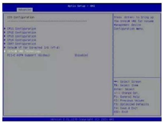
text_image
Aptio Setup - PMI Aptio Setup CPU1 Configuration CPU2 Configuration CPU3 Configuration CPU4 Configuration CPU5 Configuration System VT for Delivered EDS (VT-4) System VDD Technologies PCI-E ASPM Support / [BLown] [BLown] Press: Divers to bring up the Intel VM for volume management device Configuration menu. →: Select Screen TA: Select Ctem Enter: Select +/-: Change Dot, F1: General Help F2: Previous Values F3: Optimized Defaults F4: Save & Exit EDD: Exit
text_image
Antio Setup - Ant Advanced Intel® VHD Technology Intel® VHD for Value Management Device on CPU1 Intel® VHD for Value Management Device on CPU2 Intel® VHD for Value Management Device on CPU3 Intel® VHD for Value Management Device on CPU4 + : Select Screen B: Select, Item Enter: Select +:- Change Opt. P: General Help M2: Previous Values P: Before Valid Defaults P: Move & Exit MCC: Exit version 5.21.170 Copyright 0C1 Data.mcl
text_image
Antio Setup - AMI VMD Config for 300 U Enable/Disable VMD [Enable] NMe01 VMD [Enable] NMe02 VMD [Enable] NMe04 VMD [Enable] NMe05 VMD [Enable] Hot Plug Enable [Enable] VMD Config for 300 U Enable/Disable VMD [Enable] NMe01 VMD [Enable] NMe02 VMD [Enable] NMe03 VMD [Enable] Hot Plug Enable [Enable] VMD Config for 300 U Enable/Disable VMD [Enable] NMe02 VMD [Enable] NMe02 VMD [Enable] NMe03 VMD [Enable] Hot Plug Enable [Enable] Enable/Disable VMD [Enable] NMe01 VMD [Enable] NMe02 VMD [Enable] NMe03 VMD [Enable] Hot Plug Enable [Enable] Enable/Disable VMD [Enable] NMe01 VMD [Enable] NMe02 VMD [Enable] NMe03 VMD [Enable] Hot Plug Enable [Enable] Enable/Disable VMD [Enable] NMe01 VMD [Enable] NMe02 VMD [Enable] NMe04 VMD [Enable] NMe05 VMD [Enable] Hot Plug Enable [Enable] Enable/Disable VMD [Enable] NMe01 VMD [Enable] NMe02 VMD [Enable] NMe03 VMD [Enable] Hot Plug Enable [Enable]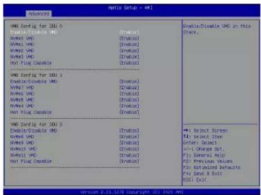
text_image
Antio Setup - Anti Advanced VMD Config for IDU 6 Enable/Disable VMD [Enable] Name: VMD [Enable] Name: VMD [Enable] Name: VMD [Enable] Name: VMD [Enable] Not Plug Capable [Enable] VMD Config for IDU 3 Enable/Disable VMD [Enable] Name: VMD [Enable] Name: VMD [Enable] Name: VMD [Enable] Name: VMD [Enable] Not Plug Capable [Enable] VMD Config for IDU 5 Enable/Disable VMD [Enable] Name: VMD [Enable] Name: VMD [Enable] Name: VMD [Enable] Name: VMD [Enable] Not Plug Capable [Enable] Enable/Disable VMD [Enable] Name: VMD [Enable] Name: VMD [Enable] Name: VMD [Enable] Name: VMD [Enable] Not Plug Capable [Enable] Enable/Disable VMD in this Place. +1 Select Screps F1: Select Item Enter: Select +/-1 Change Opt. F1: General Help F2: Previous Values F3: Default Defaults F4: Save & Exit RSD: Exit Version 2.21.1278 Copyright 01. 2023 Anti
text_image
AutoCAD Setup - AHI Note: Advanced Event Logs SPML Security Back Save & Exit Server HE Information POH SATA Configuration POH eDATA Configuration Netroot Configuration EXDF Server Configuration PCIe/PCIe/PDF Configuration Super 10 Configuration Serial Port Console Redirection ACPI Settings Trustrust Computing HTTP Boot Configuration XCET Configuration Intel(R) Ethernet Controller XTSU for 100MWD T - DC/ECE/F30/DC/FR Intel(R) Ethernet Controller XTSU for 100MWD T - DC/ECE/F30/DC/FR Intel(R) Ethernet Controller XTSU for 10 Gigabit SPT+ DC/ECE/F30/DC/FR Intel(R) Ethernet Controller XTSU for 10 Gigabit SPT+ DC/ECE/F30/DC/FR TLS Authenticate Configuration Select Virtual HDS-4.5 Driver Health This format will be the user to manage wireless Virtual HDS or CFI → Select Server R4: Select Item Enter Select +/- Change Opt... F1: General HESD F2: Previous Values F3: Optimized Defaults F4: Save & Exit GSCY Exit Version 6.21.CTM Copyright 6.21.CS21.MI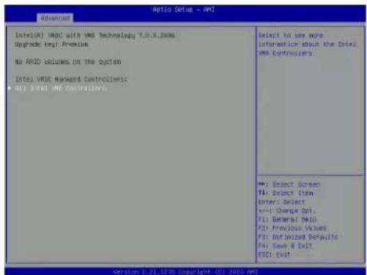
text_image
Advanced Date1(V) V80C with V80 Technology 7.0.0.2006 Upgrade key: Premium No RMS volumes on the system Date1 V80E Market Controllers - All 3 out V80 Controllers Select to see more information about the Date2 V80 Controllers +: Select Screen T4: Select Item Enter: Select +/- Change Opt. F1: General Help F2: Previous Values F3: Default Defaults F4: Save & Exit ESC: Exit Version 0.21.125 Copyright - 01. 2010 AMFigure 6-2. BIOS VMD Setting Examples
Note: BIOS screenshots are for illustration purposes. Your BIOS options may differ from those shown.
Status Indications
An LED indicator on the drive carrier shows the RAID status of the drive.
| Drive Carrier Status LED Indicator | |
| Status State (red) | |
| Normal function Off | |
| Locating 4 Hz blinking | |
| Fault Solid on | |
| Rebuilding 1 Hz blinking | |
IBPI SFF 8489 Defined Status LED States
Hot Swap Drives
Intel VMD enables hot-plug and hot-unplug for NVMe SSDs, whether from Intel or other manufacturers. Under vSphere ESXi, several steps are necessary to avoid potential stability issues. See the information at link [1] below.
Hot-unplug
- Prevent devices from being re-detected during rescan:
esxcli storage core claiming autoclaim --enabled=false - Unmount the VMFS volumes on the device. Check [2] for details.
- Detach the device. Check [3] for details.
- Physically remove the device.
Hot-plug
• Physically install the device.
ESXi will automatically discover NVMe SSDs, but a manual scan may be required in some cases.
Related Information Links
[1] https://kb.vmware.com/s/article/2151404
[2] https://docs.vmware.com/en/VMware-vSphere/6.5/com.vmware.vsphere.storage.doc/GUID-1B56EF97-F60E-4F21-82A7-8F2A7294604D.html
[3] https://docs.vmware.com/en/VMware-vSphere/6.5/com.vmware.vsphere.storage.doc/GUID-F2E75F67-740B-4406-9F0C-A2D99A698F2A.html
Chapter 7
Troubleshooting and Support
7.1 Information Resources
Website
A great deal of information is available on the Supermicro website, supermicro.com.
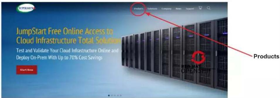
text_image
SuperService JumpStart Free Online Access to Cloud Infrastructure Total Solution Test and Validate Your Cloud Infrastructure Online and Deploy On-Prem With Up to 70% Cost Savings. Start Now Products Products Solutions Company New Support Products OPENSHUTFigure 7-1. Supermicro Website
- Specifications for servers and other hardware are available by clicking the Products option.
Direct Links for the SSG-110P-NTR10/NTR10-EU System
SSG-110P-NTR10/NTR10-EU specifications page
X12SPO-NTF motherboard page for links to the Quick Reference Guide, User Manual, validated storage drives, etc.
BPN-SAS3-LB16A-N10 Backplane Manual
Direct Links for General Support and Information
Frequently Asked Questions
Add-on card descriptions
TPM User Guide
General Memory Configuration Guide: X12
BMC User Guide
SuperDoctor5 Large Deployment Guide
For validated memory, use our Product Resources page
Direct Links (continued)
Product Matrices page for links to tables summarizing specs for systems, motherboards, power supplies, riser cards, add-on cards, etc.
Security Center for recent security notices
Supermicro Phone and Addresses
7.2 Baseboard Management Controller (BMC)
The system supports the Baseboard Management Controller (BMC). BMC is used to provide remote access, monitoring and management. There are several BIOS settings that are related to BMC.
For general documentation and information on BMC, please visit our website at: https://www.supermicro.com/en/solutions/management-software/bmc-resources.
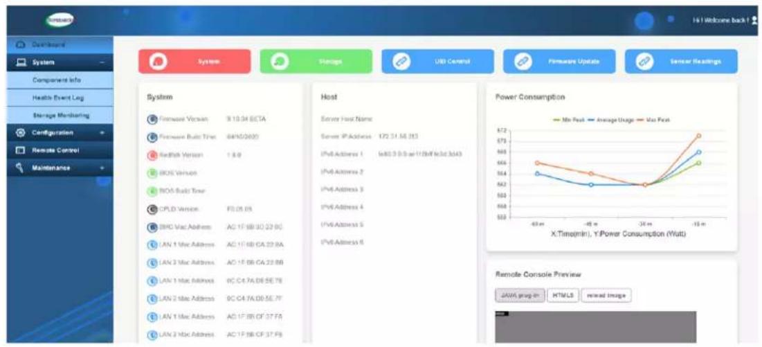
text_image
System Storage USB Control Firmware Update Sensor Readings Component Info Health Event Log Storage Monitoring Configuration Remote Control Maintenance System Firmware Vcsain 9:10:04 BCTA Firmware Build Time 04/10/2020 Redfish Version 1.8.9 BOS Version BOS Build Time CPLD Version F0:26.05 BNC Mac Address AG 1F:BB:30:22.8C LAN 1 Mac Address AC 1F:BB:CA:22.8A LAN 2 Mac Address AC 1F:BB:CA:22.8B LAN 1 Mac Address 9C:C4:7A:DE:SE.7B LAN 2 Mac Address 9C:C4:7A:DE:SE.7F LAN 1 Mac Address AC 1F:BB:CF:37.FA LAN 2 Mac Address AC 1F:BB:CF:37.FB Host Server Host Name Server IP Address 172.31.56.213 IPv6 Address 1 IsAt 3-0.0 at 17.8% (IsAt 3d43) IPv6 Address 2 IPv6 Address 3 IPv6 Address 4 IPv6 Address 5 IPv6 Address 6 Power Consumption Min Peak Average Usage Max Peak X.Time(min), Y:Power Consumption (Watt) Remote Console Preview JAVA group-in HTML/LS mixed ImageFigure 7-2. BMC Sample
7.3 Troubleshooting Procedures
Use the following procedures to troubleshoot your system. If you have followed all of the procedures below and still need assistance, refer to the Technical Support Procedures or Returning Merchandise for Service section(s) in this chapter. Power down the system before changing any non hot-swap hardware components.
General Technique
If you experience unstable operation or get no boot response, try:
- With power off, remove all but one DIMM and other added components, such as add-on cards, from the motherboard. Make sure the motherboard is not shorted to the chassis.
- Set all jumpers to their default positions.
- Power up. If the system boots, check for memory errors and add-on card problems.
No Power
- Check that the power LED on the motherboard is on.
• Make sure that the power connector is connected to the power supply. - Check that the motherboard battery still supplies approximately 3 VDC. If it does not, replace it.
- Check that the system input voltage is 100-120 VAC or 180-240 VAC.
• Turn the power switch on and off to test the system
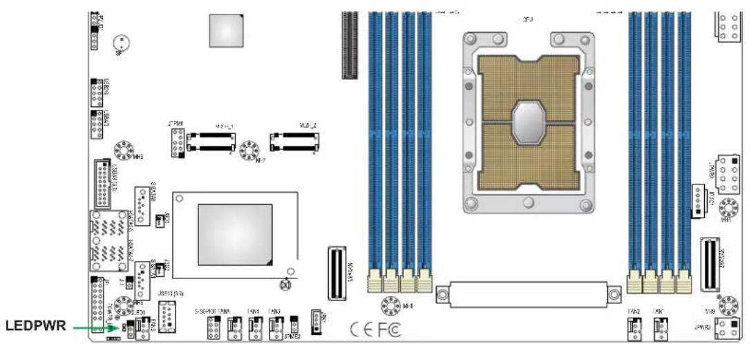
text_image
LEDPWR CPU M1 M2 M3 M4 M5 M6 M7 M8 M9 M10 M11 M12 M13 M14 M15 M16 M17 M18 M19 M20 M21 M22 M23 M24 M25 M26 M27 M28 M29 M30 CEFCFigure 7-3. Location of the MB Power LED
No Video
If the power is on but you have no video, remove all add-on cards and cables.
System Boot Failure
If the system does not display Power-On-Self-Test (POST) or does not respond after the power is turned on, try the following:
- Turn on the system with only one DIMM module installed. If the system boots, check for bad DIMM modules or slots by following the Memory Errors Troubleshooting procedure below.
Memory Errors
- Make sure that the DIMM modules are properly and fully installed.
- Confirm that you are using the correct memory. Also, it is recommended that you use the same memory type and speed for all DIMMs in the system. See Section 3.4 for memory details.
- Check for bad DIMM modules or slots by swapping modules between slots and noting the results.
Losing the System Setup Configuration
- Always replace power supplies with the exact same model that came with the system. A poor quality power supply may cause the system to lose the CMOS setup configuration.
- Check that the motherboard battery still supplies approximately 3 VDC. If it does not, replace it.
If the above steps do not fix the setup configuration problem, contact your vendor for repairs.
When the System Becomes Unstable
If the system becomes unstable during or after OS installation, check the following:
- CPU/BIOS support: Make sure that your CPU is supported and that you have the latest BIOS installed in your system.
-
Memory: Make sure that the memory modules are supported. Refer to the product page on our website at www.supermicro.com. Test the modules using memtest86 or a similar utility.
• Storage drives: Make sure that all drives work properly. Replace if necessary. -
System cooling: Check that all heatsink fans and system fans work properly. Check the hardware monitoring settings in the BMC to make sure that the CPU and system temperatures are within the normal range. Also check the Control panel Overheat LED.
- Adequate power supply: Make sure that the power supply provides adequate power to the system. Make sure that all power connectors are connected. Refer to the Supermicro website for the minimum power requirements.
- Proper software support: Make sure that the correct drivers are used.
If the system becomes unstable before or during OS installation, check the following:
- Source of installation: Make sure that the devices used for installation are working properly, including boot devices.
- Cable connection: Check to make sure that all cables are connected and working properly.
- Use the minimum configuration for troubleshooting: Remove all unnecessary components (starting with add-on cards first), and use the minimum configuration (but with a CPU and a memory module installed) to identify the trouble areas.
- Identify a bad component by isolating it. Check and change one component at a time.
- Remove a component in question from the chassis, and test it in isolation. Replace it if necessary.
- Or swap in a new component for the suspect one.
- Or install the possibly defective component into a known good system. If the new system works, the component is likely not the cause or the problem.
7.4 BIOS Error Beep (POST) Codes
During the POST (Power-On Self-Test) routines, which are performed each time the system is powered on, errors may occur.
Non-fatal errors are those which, in most cases, allow the system to continue the boot-up process. The error messages normally appear on the screen.
Fatal errors are those which will not allow the system to continue the boot-up procedure. If a fatal error occurs, you should consult with your system manufacturer for possible repairs.
These fatal errors are usually communicated through a series of audible beeps. The table below lists some common errors and their corresponding beep codes encountered by users.
| BIOS Error Beep (POST) Codes | ||
| Beep Code Error | Message Description | |
| 1 short Refresh Circuits have been reset (Ready to power up) | ||
| 5 short, 1 long Memory error No memory detected in system | ||
| 5 long, 2 short Display memory read/write error Video adapter missing or with faulty memory | ||
| 1 long continuous System OH System overheat condition | ||
Additional BIOS POST Codes
The AMI BIOS supplies additional checkpoint codes, which are documented online at http://www.supermicro.com/support/manuals/ ("AMI BIOS POST Codes User's Guide").
When BIOS performs the Power On Self Test, it writes checkpoint codes to I/O port 0080h. If the computer cannot complete the boot process, a diagnostic card can be attached to the computer to read I/O port 0080h (Supermicro p/n AOC-LPC80-20).
For information on AMI updates, please refer to http://www.ami.com/products/.
7.5 Crash Dump Using BMC
In the event of a processor internal error (IERR) that crashes your system, you may want to provide information to support staff. You can download a crash dump of status information using BMC. The BMC manual is available at https://www.supermicro.com/en/solutions/management-software/bmc-resources.
Check BMC Error Log
- Access the BMC web interface.
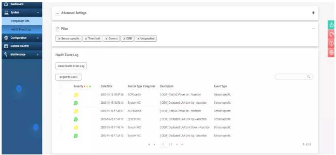
text_image
Dashboard System Components Info Health Event Log Configuration + Remote Control + Maintenance + Advanced Settings Filter x Sensor-specific x Threshold x Generic x OEM x Unspecified Health Event Log Clear Health Event Log Export to Excel Severity Data/Time Sensor Type Categories Description Event Type 2020-10-15 18:57:06 ACPowerOn [OEM] First AC Power on - Assertion Sensor specific 2020-10-15 18:58:43 System NC [OEM] Dedicated LAN Link Up - Assertion Sensor specific 2020-10-15 17:41:57 ACPowerOn [OEM] First AC Power on - Assertion Sensor specific 2020-10-15 17:41:17 System NC [OEM] Dedicated LAN Link Up - Assertion Sensor specific 2020-10-15 17:41:14 System NC [OEM] Dedicated LAN Link Down - Assertion Sensor specific 2020-10-15 17:41:12 System NC [OEM] Dedicated LAN Link Up - Assertion Sensor specific + + + / + / + + 1.6/6Figure 7-4. BMC Event Log
- Click the Server Health tab, then Event Log to verify an IERR error.
In the event of an IERR, the BMC executes a crash dump. You must download the crash dump and save it.
7.6 UEFI BIOS Recovery
Warning: Do not upgrade the BIOS unless your system has a BIOS-related issue. Flashing the wrong BIOS can cause irreparable damage to the system. In no event shall Supermicro be liable for direct, indirect, special, incidental, or consequential damages arising from a BIOS update. If you do update the BIOS, do not shut down or reset the system while the BIOS is updating to avoid possible boot failure.
Overview
The Unified Extensible Firmware Interface (UEFI) provides a software-based interface between the operating system and the platform firmware in the pre-boot environment. The UEFI specification supports an architecture-independent mechanism that will allow the UEFI OS loader stored in an add-on card to boot the system. The UEFI offers clean, hands-off management to a computer during system boot.
Recovering the UEFI BIOS Image
A UEFI BIOS flash chip consists of a recovery BIOS block and a main BIOS block (a main BIOS image). The recovery block contains critical BIOS codes, including memory detection and recovery codes for the user to flash a healthy BIOS image if the original main BIOS image is corrupted. When the system power is turned on, the recovery block codes execute first. Once this process is complete, the main BIOS code will continue with system initialization and the remaining POST (Power-On Self-Test) routines.
Note 1: Follow the BIOS recovery instructions below for BIOS recovery when the main BIOS block crashes.
Note 2: When the BIOS recovery block crashes, you will need to follow the procedures to make a Returned Merchandise Authorization (RMA) request. Also, you may use the Supermicro Update Manager (SUM) Out-of-Band (https://www.supermicro.com.tw/products/nfo/SMS_SUM.cfm) to reflash the BIOS.
Recovering the Main BIOS Block with a USB Device
This feature allows the user to recover the main BIOS image using a USB-attached device without additional utilities used. A USB flash device such as a USB Flash Drive, or a USB CD/DVD ROM/RW device can be used for this purpose. However, a USB Hard Disk drive cannot be used for BIOS recovery at this time.
The file system supported by the recovery block is FAT (including FAT12, FAT16, and FAT32) which is installed on a bootable or non-bootable USB-attached device. However, the BIOS might need several minutes to locate the SUPER.ROM file if the media size becomes too large due to the huge volumes of folders and files stored in the device.
To perform UEFI BIOS recovery using a USB-attached device, follow the instructions below.
- Using a different machine, copy the "Super.ROM" binary image file into the Root "\" directory of a USB device or a writable CD/DVD.
Note 1: If you cannot locate the "Super.ROM" file in your drive disk, visit our website at www.supermicro.com to download the BIOS package. Extract the BIOS binary image into a USB flash device and rename it "Super.ROM" for the BIOS recovery use.
Note 2: Before recovering the main BIOS image, confirm that the "Super.ROM" binary image file you download is the same version or a close version meant for your motherboard. - Insert the USB device that contains the new BIOS image ("Super.ROM") into your USB drive and reset the system when the following screen appears.
- After locating the healthy BIOS binary image, the system will enter the BIOS Recovery menu as shown below.
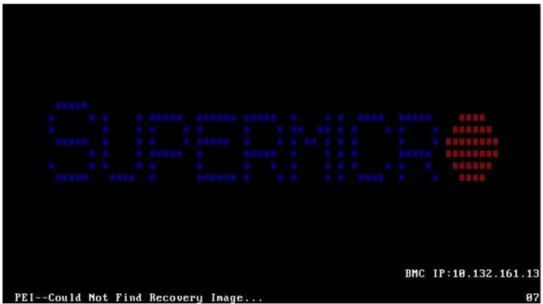
text_image
SUPERIOR BMC IP:10.132.161.13 PEI--Could Not Find Recovery Image... 87Note: At this point, you may decide if you want to start the BIOS recovery. If you decide to proceed with BIOS recovery, follow the procedures below.
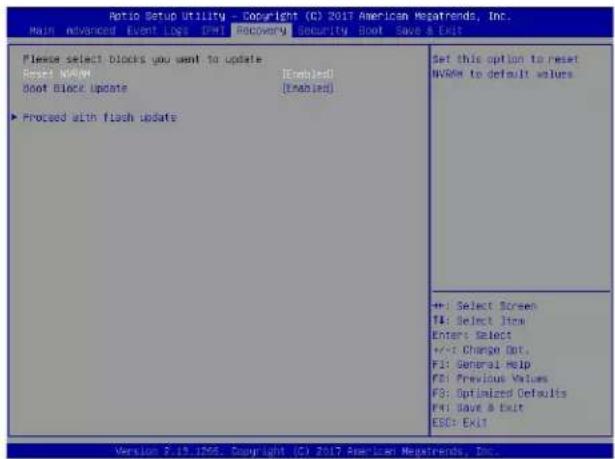
text_image
Ratio Setup Utility - Copyright (C) 2017 American Megatrends, Inc. Main Advanced Event Logs Ctrl Recovery Security Boot Save a Exit Please select blocks you want to update Reset: NVR6M [Enabled] Boot Block Update [Enabled] ► Proceed with flash update Set this option to reset NVR6M to default values +: Select Screen T4: Select Item Enter: Select +/-: Change Out. F1: General Help F2: Previous Values F3: Optimized Defaults F4: Save & Exit ESC: Exit Version 2.19.1706. Copyright (C) 2017 American Megatrends, Inc.- When the screen as shown above displays, use the arrow keys to select the item "Proceed with flash update" and press the
key. You will see the BIOS recovery progress as shown in the screen below.
Note: Do not interrupt the BIOS flashing process until it has completed.
- After the BIOS recovery process is complete, press any key to reboot the system.
- Using a different system, extract the BIOS package into a USB flash drive.

text_image
Auto Setup Utility - Copyright (C) 2017 American Regatrends, Inc. Recovery WARNING System firmware is being updated. Keyboard is locked. DO NOT TURN THE POWER OFF!!. Once firmware update is completed press any key to reboot the system Program new data Write new boot block... 17% +: Select Screen T4: Select Items Enter: Select +/-: Change Opt. F1: General Help F2: Previous Values F3: Optimized Defaults F4: Save & Exit ESC: Exit Version 2.15.1266, Copyright (C) 2017 American Regatrends, Inc.- Press
continuously during system boot to enter the BIOS Setup utility. From the top of the tool bar, select Boot to enter the submenu. From the submenu list, select Boot
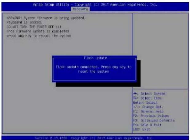
text_image
Ratio Setup Utility - Copyright (C) 2017 American Megatrends, Inc. Recoverers WARNING: System firmware is being updated, Keyboard is locked. DO NOT TURN THE POWER OFF !!! Once firmware update is completed Press any key to reboot the system Flash update Flash update completed. Press any key to reset the system +: Select Screen F1: Select Item Enter: Select +/-: Change Opt. F1: General Help F2: Previous Values F3: Optimized Defaults F4: Save & Exit G8D: Exit Version 2.19, ID56, Copyright (C) 2017 American Megatrends, Inc.Option #1 as shown below. Then, set Boot Option #1 to [UEFI AP:UEFI: Built-in EFI Shell]. Press
- When the UEFI Shell prompt appears, type fs# to change the device directory path. Go to the directory that contains the BIOS package you extracted earlier from Step 6. Enter flash.nsh BIOSname.### at the prompt to start the BIOS update process.
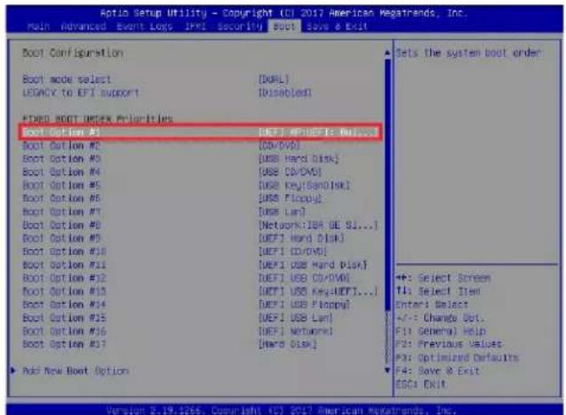
text_image
Auto Setup Utility - Copyright (CI) 2017 American Megatrends, Inc. Main Advanced Event Logs JPMS Security SCOTs Save & Exit Boot Configuration Boot mode select [DOBL] LEGACY to EPI Support [Disabled] EXP# BOOT INDEX Priorities Boot Option #3 [DEFI MP/DEFI: Max...] Boot Option #2 [DD/VVD] Boot Option #3 [USB Hard Disk] Boot Option #4 [USB CD/DVI] Boot Option #5 [USB Key[ScanDisk]] Boot Option #6 [USB Floppy] Boot Option #7 [USB Lan] Boot Option #8 [Network:JBA GE SI...] Boot Option #9 [DEFI Hard Disk] Boot Option #10 [DEFI CD/DVD] Boot Option #11 [DEFI USB Hard Disk] Boot Option #12 [DEFI USB CD/DVI] Boot Option #13 [DEFI USB Key:UEFI...] Boot Option #14 [DEFI USB Floppy] Boot Option #15 [DEFI USB Lan] Boot Option #16 [DEFI Network] Boot Option #17 [Halo Disk] Add New Boot Option Sets the system boot order +: Select Screen TI: Select Item Enter: Select +/-: Change Opt. F1: General) Help F2: Previous Values F3: Optimized Defaults F4: Save & Exit ESC: Exit Version 2.19.1266. Copyright (CI) 2017 American Megatrends, Inc.Note: Do not interrupt this process until the BIOS flashing is complete.

text_image
UEFI Interactive Shell v2.1 EDI: II UEFI v2.50 (American Regatrends, 0x00890XX) Mapping table: FS0: A106(s1):H0D0(s2):BLK1; Ps:Root(0x0)/Pc(0x14,0x0)/USB(0x11,0x0)/M0II,MER,xGSP91D2,0x800,0x1 CRASSO BLK0: Rldo(s): Ps:Root(0x0)/Pc(0x14,0x0)/USB(0x11,0x0) Press FSS to 1 seconds to skills startup.moh or any other key to continue. Shell: fss FS0: CS FLOODS FS0:WPLOOS> CS SHAPHE2_03162012 FS0:WPLOOS\SHAPHE2_03162017\ flash.nsh X13F07.34_- The screen above indicates that the BIOS update process is complete. When you see the screen above, unplug the AC power cable from the power supply, clear CMOS, and plug
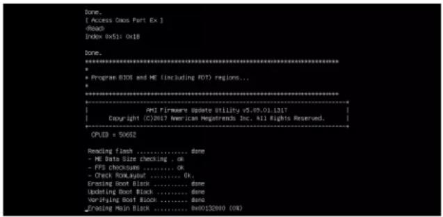
text_image
Done. [ Access Oxxs Part Ex ]text_image
Verifying NCR Block ....... done - Update success for FDR - Update success for ES. - Successful update Recovery Loader to 0PRx!! - Successful update MFBII-- - Successful update FFMII-- - Successful update WFS, TWSI and TWS2!! - Successful update FIOO and UIOK!! - ME Entire Image update success!! WORINO: System must power-off to have the changes take effect!! Moving FSO:\AFU005\SNPME2_03162017\40x64,efi -> FSO:\AFU005\SNPME2_03162017\f df.soc - [es] Moving FSO:\AFU005\SNPME2_03162017\afumfix4.efi -> FSO:\AFU005\SNPME2_03162017 Parufesi.soc - [es] ********************************************************************** * - please ignore this 'Shell' cannot read from file - device error * - warning message due to it does not impact flashing process. ********************************************************************** Deleting ' Delete successful. FSO:>7.7 CMOS Clear
JBT1 is used to clear CMOS, which will also clear any passwords. Instead of pins, this jumper consists of contact pads to prevent accidentally clearing the contents of CMOS.To Clear CMOS
1. First power down the system completely. 2. Remove the top cover to access the motherboard. 3. Remove the onboard battery from the motherboard. 4. Short the CMOS pads with a metal object such as a small screwdriver for at least four seconds. 5. Remove the screwdriver or shorting device. 6. Replace the cover, reconnect the power cords and power on the system. Notes: Clearing CMOS will also clear all passwords. Do not use the PW\_ON connector to clear CMOS.  JBT1 contact pads7.8 Where to Get Replacement Components
If you need replacement parts for your system, to ensure the highest level of professional service and technical support, purchase exclusively from our Supermicro Authorized Distributors/System Integrators/Resellers. A list can be found at: http://www.supermicro.com. Click the "Where to Buy" tab.7.9 Reporting an Issue
Technical Support Procedures
Before contacting Technical Support, please take the following steps. If your system was purchased through a distributor or reseller, please contact them for troubleshooting services. They have the best knowledge of your specific system configuration. 1. Please review the Troubleshooting Procedures in this manual and Frequently Asked Questions on our website before contacting Technical Support. 2. BIOS upgrades can be downloaded from our website. Note: Not all BIOS can be flashed depending on the modifications to the boot block code. 3. If you still cannot resolve the problem, include the following information when contacting us for technical support: - System, motherboard, and chassis model numbers and PCB revision number - BIOS release date/version (this can be seen on the initial display when your system first boots up) - System configuration An example of a Technical Support form is posted on our website. Distributors: For immediate assistance, please have your account number ready when contacting our technical support department by email.Returning Merchandise for Service
A receipt or copy of your invoice marked with the date of purchase is required before any warranty service will be rendered. You can obtain service by calling your vendor for a Returned Merchandise Authorization (RMA) number. When returning to the manufacturer, the RMA number should be prominently displayed on the outside of the shipping carton, and mailed prepaid or hand-carried. Shipping and handling charges will be applied for all orders that must be mailed when service is complete. For faster service, RMA authorizations may be requested online (http://www.supermicro.com/support/rma/). Whenever possible, repack the chassis in the original Supermicro carton, using the original packaging material. If these are no longer available, be sure to pack the chassis securely, using packaging material to surround the chassis so that it does not shift within the carton and become damaged during shipping. This warranty only covers normal consumer use and does not cover damages incurred in shipping or from failure due to the alteration, misuse, abuse or improper maintenance of products. During the warranty period, contact your distributor first for any product problems.Vendor Support Filing System
For issues related to Intel, use the Intel IPS filing system: https://www.intel.com/content/www/us/en/design/support/ips/training/welcome.html For issues related to Red Hat Enterprise Linux, since it is a subscription based OS, contact your account representative.7.10 Feedback
Supermicro values your feedback as we strive to improve our customer experience in all facets of our business. Please email us at techwriterteam@supermicro.com to provide feedback on our manuals.Appendix A
Standardized Warning Statements for AC Systems
About Standardized Warning Statements
The following statements are industry standard warnings, provided to warn the user of situations which have the potential for bodily injury. Should you have questions or experience difficulty, contact Supermicro's Technical Support department for assistance. Only certified technicians should attempt to install or configure components. Read this appendix in its entirety before installing or configuring components in the Supermicro chassis. These warnings may also be found on our website at http://www.supermicro.com/about/policies/safety\_information.cfm.Warning Definition
Warning! This warning symbol means danger. You are in a situation that could cause bodily injury. Before you work on any equipment, be aware of the hazards involved with electrical circuitry and be familiar with standard practices for preventing accidents. 警告の定義 この警告サインは危険を意味します。 人身事故につながる可能性がありますので、いずれの機器でも動作させる前に、 電気回路に含まれる危険性に注意して、標準的な事故防止策に精通して下さい。 此警告符号代表危险。 您正处于可能受到严重伤害的工作环境中。在您使用设备开始工作之前,必须充分意识到触电的危险,并熟练掌握防止事故发生的标准工作程序。请根据每项警告结尾的声明号码找到此设备的安全性警告说明的翻译文本。 此警告符號代表危險。 您正處於可能身體可能會受損傷的工作環境中。在您使用任何設備之前,請注意觸電的危險,並且要熟悉預防事故發生的標準工作程序。請依照每一注意事項後的號碼找到相關的翻譯說明內容。 WarnungWICHTIGE SICHERHEITSHINWEISE
Dieses Warnsymbol bedeutet Gefahr. Sie befinden sich in einer Situation, die zu Verletzungen führen kann. Machen Sie sich vor der Arbeit mit Geräten mit den Gefahren elektrischer Schaltungen und den üblichen Verfahren zur Vorbeugung vor Unfällen vertraut. Suchen Sie mit der am Ende jeder Warnung angegebenen Anweisungsnummer nach der jeweiligen Übersetzung in den übersetzten Sicherheitshinweisen, die zusammen mit diesem Gerät ausgeliefert wurden. BEWAHREN SIE DIESE HINWEISE GUT AUF.INSTRUCCIONES IMPORTANTES DE SEGURIDAD
Este símbolo de aviso indica peligro. Existe riesgo para su integridad física. Antes de manipular cualquier equipo, considere los riesgos de la corriente eléctrica y familiarícese con los procedimientos estándar de prevención de accidentes. Al anal de cada advertencia encontrará el número que le ayudará a encontrar el texto traducido en el apartado de traducciones que acompaña a este dispositivo. GUARDE ESTAS INSTRUCCIONES.IMPORTANTES INFORMATIONS DE SÉCURITÉ
Ce symbole d'avertissement indique un danger. Vous vous trouvez dans une situation pouvant entraîner des blessures ou des dommages corporels. Avant de travailler sur un équipement, soyez conscient des dangers liés aux circuits électriques et familiarisez-vous avec les procédures couramment utilisées pour éviter les accidents. Pour prendre connaissance des traductions des avertissements ☐gurant dans les consignes de sécurité traduites qui accompagnent cet appareil, référez-vous au numéro de l'instruction situé à la ☐n de chaque avertissement. CONSERVEZ CES INFORMATIONS. תְרָה בְּרָה בְּרָה תְבָרִי אַלְה בְּרִי אַלְה בְּרִי אַלְה בְּרִי אַלְה בְּרִי אַלְה בְּרִי אַלְה בְּרִי אַלְה בְּרִם אַלְה בְּרִי אַלְה בְּרִי אַלְה בְּרִי אַלְה בְּרִי אַלְה בְּרִי אַלְה בְּרִי אַדָא לֶת הָא לֶת הָא לֶת הָא לֶת הָא לֶת הָא לֶת הָא לֶת הָא לֶת הָא לֶת הָא לֶת הָא לֶת הָא לֶת הָא לֶת הָא וֹשׁו اَكَّ فحالة وَكَى أي تسبب ف ا صابة ج Designer هذا الزهر عُ خطز !تحذ زُ. قبل أي تعول على أي هعذات، كي على علن بالوخاطز ال أجوة عي الذوائر الكهزباي ة وَيْ عَلَى دَرَا ةُ بالَوَارِسَاتِ الْقَائِّةِ لُوْعُ وَقَعَ أَيْ حَنَادِث استخدم رقن الب إي الو صص ف ها ء كل تحذ ز لloxشر تزجوتها 안전을 위한 주의사항 경고! 이 경고 기호는 위험이 있음을 알려 줍니다. 작업자의 신체에 부상을 야기 할 수 있는 상태에 있게 됩니다. 모든 장비에 대한 작업을 수행하기 전에 전기회로와 관련된 위험요소들을 확인하시고 사전에 사고를 방지할 수 있도록 표준 작업절차를 준수해 주시기 바랍니다. 해당 번역문을 찾기 위해 각 경고의 마지막 부분에 제공된 경고문 번호를 참조하십시오BELANGRIJKE VEILIGHEIDSINSTRUCTIES
Dit waarschuwings symbool betekent gevaar. U verkeert in een situatie die lichamelijk letsel kan veroorzaken. Voordat u aan enige apparatuur gaat werken, dient u zich bewust te zijn van de bij een elektrische installatie betrokken risico's en dient u op de hoogte te zijn van de standaard procedures om ongelukken te voorkomen. Gebruik de nummers aan het eind van elke waarschuwing om deze te herleiden naar de desbetreffende locatie. BEWAAR DEZE INSTRUCTIESInstallation Instructions
 Warning! Read the installation instructions before connecting the system to the power source. 設置手順書 システムを電源に接続する前に、設置手順書をお読み下さい。 警告 将此系统连接电源前,请先阅读安装说明。 警告 將系統與電源連接前,請先閱讀安裝說明。 Warnung Vor dem Anschließen des Systems an die Stromquelle die Installationsanweisungen lesen. ¡Advertencia! Lea las instrucciones de instalación antes de conectar el sistema a la red de alimentación. Attention Avant de brancher le système sur la source d'alimentation, consulter les directives d'installation. .תְקָרִי לַלְאָה בְּרִי לַלְאָה בְּרִי לַלְאָה בְּרִי לַלְאָה בְּרִי לַלְאָה اقر إرشادات التركيب قبل توصيل النظام إلى مصر للطاقة 시스템을 전원에 연결하기 전에 설치 안내를 읽어주십시오. Waarschuwing Raadpleeg de installatie-instructies voordat u het systeem op de voedingsbron aansluit.Circuit Breaker
 Warning! This product relies on the building's installation for short-circuit (overcurrent) protection. Ensure that the protective device is rated not greater than: 250 V, 20 A. サーキット・ブレーカー この製品は、短絡(過電流)保護装置がある建物での設置を前提としています。 保護装置の定格が250 V、20 Aを超えないことを確認下さい。 警告 此产品的短路(过载电流)保护由建筑物的供电系统提供,确保短路保护设备的额定电流不大于250V,20A。 警告 此產品的短路(過載電流)保護由建築物的供電系統提供,確保短路保護設備的額定電流不大於250V,20A。Warnung
Dieses Produkt ist darauf angewiesen, dass im Gebäude ein Kurzschluss- bzw. Überstromschutz installiert ist. Stellen Sie sicher, dass der Nennwert der Schutzvorrichtung nicht mehr als: 250 V, 20 A beträgt.¡Advertencia!
Este equipo utiliza el sistema de protección contra cortocircuitos (o sobrecorrientes) del edificio. Asegúrese de que el dispositivo de protección no sea superior a: 250 V, 20 A.Attention
Pour ce qui est de la protection contre les courts-circuits (surtension), ce produit dépend de l'installation électrique du local. Vérifiez que le courant nominal du dispositif de protection n'est pas supérieur à :250 V, 20 A. הַעָרְפֹרִי, אַעָרְפֹרִי, אַעָרְפֹרִי, אַעָרְפֹרִי, אַעָרְפֹרִי, אַעָרְפֹרִי, אַעָרְפֹרִים, אַעָרְפֹרִים, אַעָרְפֹרִים, אַעָרְפֹרִים, אַעָרְפֹרִים, אַעָרְפֹרִים, אַעָרְפֹר 250VDC, 20A-הוּוּוּוּוּוּוּוּוּוּוּוּוּוּוּוּוּוּוּוּוּוּוּוּוּוּוּוּוּוּוּוּוּוּק هذه المنتج يعت Indeed على معداث الحمايت مه الدوائر القصيرة التي تم تAlphaithا في المبنى 20A, 250V : تأكد من أن تقييم الجهاز الوقائي ليس أكثر من경고!
이 제품은 전원의 단락(과전류)방지에 대해서 전적으로 건물의 관련 설비에 의존합니다. 보호장치의 정격이 반드시 250V(볼트), 20A(암페어)를 초과하지 않도록 해야 합니다.Waarschuwing
Dit product is afhankelijk van de kortsluitbeveiliging (overspanning) van uw electrische installatie. Controleer of het beveiligde aparaat niet groter gedimensioneerd is dan 250V, 20A.Power Disconnection Warning
 Warning! The system must be disconnected from all sources of power and the power cord removed from the power supply module(s) before accessing the chassis interior to install or remove system components (except for hot-swap components). text_image
CAUTION: This unit has redundant power sources. Please disconnect all the power cords before servicing.Waarschuwing
Voordat u toegang neemt tot het binnenwerk van de behuizing voor het installeren of verwijderen van systeem onderdelen, dient u alle spanningsbronnen en alle stroomkabels aangesloten op de voeding(en) van de behuizing te verwijderenEquipment Installation
 Warning! Only authorized personnel and qualified service persons should be allowed to install, replace, or service this equipment. 機器の設置 トレーニングを受け認定された人だけがこの装置の設置、交換、またはサービスを許可されています。 警告 只有经过培训且具有资格的人员才能进行此设备的安装、更换和维修。 警告 只有經過受訓且具資格人員才可安裝、更換與維修此設備。 Warnung Nur autorisiertes Personal und qualifizierte Servicetechniker dürfen dieses Gerät installieren, austauschen oder warten.. ¡Advertencia! Sólo el personal autorizado y el personal de servicio calificado deben poder instalar, reemplazar o dar servicio a este equipo.Attention
Seul le personnel autorisé et le personnel de maintenance qualifié doivent être autorisés à installer, remplacer ou entretenir cet équipement.. !תְרָה תְרָה בַלְבָרִי אַעֹרִי, לְרָה בַלְבָרִי אַעֹרִי, לְרָה בַלְבָרִי אַעֹרִי, לְרָה בַלְבָרִי אַעֹרִי, לְרָה ينبغي السماح فقط للموظفين المعتمدين وأفراد الخدمة المؤهلين بتركيب هذا الجهاز أو استبdateه أو صيانته 경고! 승인된 직원과 자격을 갖춘 서비스 담당자만이 이 장비를 설치, 교체 또는 서비스할 수 있습니다. Waarschuwing Alleen geautoriseerd personeel en gekwalificeerd onderhoudspersoneel mag deze apparatuur installeren, vervangen of onderhouden..Restricted Area
 Warning! This unit is intended for installation in restricted access areas. A restricted access area can be accessed only through the use of a special tool, lock and key, or other means of security. (This warning does not apply to workstations).アクセス制限区域
このユニットは、アクセス制限区域に設置されることを想定しています。 アクセス制限区域は、特別なツール、鍵と錠前、その他のセキュリティの手段を用いてのみ出入りが可能です。警告
此部件应安装在限制进出的场所,限制进出的场所指只能通过使用特殊工具、锁和钥匙或其它安全手段进出的场所。警告
此裝置僅限安裝於進出管制區域,進出管制區域係指僅能以特殊工具、鎖頭及鑰匙或其他安全方式才能進入的區域。Warnung
Diese Einheit ist zur Installation in Bereichen mit beschränktem Zutritt vorgesehen. Der Zutritt zu derartigen Bereichen ist nur mit einem Spezialwerkzeug, Schloss und Schlüssel oder einer sonstigen Sicherheitsvorkehrung möglich.¡Advertencia!
Esta unidad ha sido diseñada para instalación en áreas de acceso restringido. Sólo puede obtenerse acceso a una de estas áreas mediante la utilización de una herramienta especial, cerradura con llave u otro medio de seguridad.Attention
Cet appareil doit être installée dans des zones d'accès réservés. L'accès à une zone d'accès réservé n'est possible qu'en utilisant un outil spécial, un mécanisme de verrouillage et une clé, ou tout autre moyen de sécurité. תְבָרִיֹת אַלְעֹן אַלְעֹן !תְרָה תְרָה בַעּוֹת אַלְבָה. וְאִיָה לֶתְרָה אַלְבָה אַלְבָה אַלְבָה אַלְבָה אַלְבָה אַלְבָה אַלְבָה אַלְבָה אַלְבָה אַלְבָה אַלְגִים (לְרַעָהִי, מְרַעָהִי (בְרַעָהִי) EXECпис هذه انUCHدة نترك بُها ف مناطق محظورة تم. مَّ كن انتصال إن منقطت محظورة فقط من خلال استخاذو أداة خاصت أو أ وس هُت أخرى نلا DALAMA قفم ومفتاح 경고! 이 장치는 접근이 제한된 구역에 설치하도록 되어있습니다. 특수도구, 잠금 장치 및 키, 또는 기타 보안 수단을 통해서만 접근 제한 구역에 들어갈 수 있습니다.Waarschuwing
Dit apparaat is bedoeld voor installatie in gebieden met een beperkte toegang. Toegang tot dergelijke gebieden kunnen alleen verkregen worden door gebruik te maken van speciaal gereedschap, slot en sleutel of andere veiligheidsmaatregelen.Battery Handling
 Warning! There is the danger of explosion if the battery is replaced incorrectly. Replace the battery only with the same or equivalent type recommended by the manufacturer. Dispose of used batteries according to the manufacturer's instructions 電池の取り扱い 電池交換が正しく行われなかった場合、破裂の危険性があります。交換する電池はメーカーが推奨する型、または同等のものを使用下さい。使用済電池は製造元の指示に従って処分して下さい。 警告 电池更换不当会有爆炸危险。请只使用同类电池或制造商推荐的功能相当的电池更换原有电池。请按制造商的说明处理废旧电池。 警告 電池更換不當會有爆炸危險。請使用製造商建議之相同或功能相當的電池更換原有電池。請按照製造商的說明指示處理廢棄舊電池。 Warnung Bei Einsetzen einer falschen Batterie besteht Explosionsgefahr. Ersetzen Sie die Batterie nur durch den gleichen oder vom Hersteller empfohlenen Batterietyp. Entsorgen Sie die benutzten Batterien nach den Anweisungen des Herstellers. Attention Danger d'explosion si la pile n'est pas remplacée correctement. Ne la remplacer que par une pile de type semblable ou équivalent, recommandée par le fabricant. Jeter les piles usagées conformément aux instructions du fabricant. ¡Advertencia! Existe peligro de explosión si la batería se reemplaza de manera incorrecta. Reemplazar la batería exclusivamente con el mismo tipo o el equivalente recomendado por el fabricante. Desechar las baterías gastadas según las instrucciones del fabricante. ! תְקָרִי לַל. מְקָרִי אַלְעֹן, בְּרִי לַל. .הכלההוּרָהִיַעְבָרִיַעְבָרִיַעְבָרִיַעְבָרִיַעְבָרִיַעְבָרִיַעְבָרִיַעְבָרִיַעְבָרִי هناك خطر من انفجار في حالة اسcbdال البطارية بطريقة غير صحيحة فعليل اسحبذال البطارية فقط بنفس النع أو ما يعادلها مما أوصث به الشرمة المصنعة جملص منprobabilityات المسعملة وفقا لしています الشرمة الصناعة 경고! 배터리가 올바르게 교체되지 않으면 폭발의 위험이 있습니다. 기존 배터리와 동일하거나 제조사에서 권장하는 동등한 종류의 배터리로만 교체해야 합니다. 제조사의 안내에 따라 사용된 배터리를 처리하여 주십시오.Waarschuwing
Er is ontploffingsgevaar indien de batterij verkeerd vervangen wordt. Vervang de batterij slechts met hetzelfde of een equivalent type die door de fabrikant aanbevolen wordt. Gebruikte batterijen dienen overeenkomstig fabrieksvoorschriften afgevoerd te worden.Redundant Power Supplies
 Warning! This unit might have more than one power supply connection. All connections must be removed to de-energize the unit. 冗長電源装置 このユニットは複数の電源装置が接続されている場合があります。 ユニットの電源を切るためには、すべての接続を取り外さなければなりません。 警告 此部件连接的电源可能不止一个,必须将所有电源断开才能停止给该部件供电。 警告 此裝置連接的電源可能不只一個,必須切斷所有電源才能停止對該裝置的供電。 Warnung Dieses Gerät kann mehr als eine Stromzufuhr haben. Um sicherzustellen, dass der Einheit kein trom zugeführt wird, müssen alle Verbindungen entfernt werden. ¡Advertencia! Puede que esta unidad tenga más de una conexión para fuentes de alimentación. Para cortar por completo el suministro de energía, deben desconectarse todas las conexiones. Attention Cette unité peut avoir plus d'une connexion d'alimentation. Pour supprimer toute tension et tout courant électrique de l'unité, toutes les connexions d'alimentation doivent être débranchées. תָהַעְרִי אַלְרִי אַלְרִי אַלְרִי אַלְרִי אַלְרִי אַלְרִי אַלְרִי אַלְרִי אַלְרִי אַלְרִי אַד !תְרָה הכלההוּרָה אַלְבָרִי לֶתְאָה אַלְבָרִי לֶתְאָה אַלְבָרִי לֶתְאָה אַלְבָרִי לֶתְאָה אַלְבָרִי לֶתְאָה אַל .תְקּוֹרָה אַב قد يكون لها小微企业 عدة اتصالات بوحدات امداد الطاقة. يجب إزالة كافة اتصالات لعسل الوحدة عن الكهرباء 경고! 이 장치에는 한 개 이상의 전원 공급 단자가 연결되어 있을 수 있습니다. 이 장치에 전원을 차단하기 위해서는 모든 연결 단자를 제거해야만 합니다. Waarschuwing Deze eenheid kan meer dan één stroomtoevoeraansluiting bevatten. Alle aansluitingen dienen verwijderd te worden om het apparaat stroomloos te maken.Backplane Voltage
 Warning! Hazardous voltage or energy is present on the backplane when the system is operating. Use caution when servicing. バックプレーンの電圧 システムの稼働中は危険な電圧または電力が、バックプレーン上にかかっています。 修理する際には注意ください。 警告 当系统正在进行时,背板上有很危险的电压或能量,进行维修时务必小心。 警告 當系統正在進行時,背板上有危險的電壓或能量,進行維修時務必小心。 Warnung Wenn das System in Betrieb ist, treten auf der Rückwandplatine gefährliche Spannungen oder Energien auf. Vorsicht bei der Wartung. ¡Advertencia! Cuando el sistema está en funcionamiento, el voltaje del plano trasero es peligroso. Tenga cuidado cuando lo revise. Attention Lorsque le système est en fonctionnement, des tensions électriques circulent sur le fond de panier. Prendre des précautions lors de la maintenance. תְרָה בְּרָה בְּרָה !תְרָה תְבָרִי הַלְהָה אַעֹן. בְּרִי הַלְהָה אַעֹן, לְרֵם הַלְהָה אַעֹן, לְרֵם הַלְהָה אַעֹן, לְרֵם הַלְהָה אַעֹן, לְרֵם הַלְהָה אַעֹן, לְרֵי .תְרָׁבַע هناك خطز مه التيار الكهزبائي أو الطاقة الم congressional على اللحة عندما يكن nlنظام يعمل كه حذرا عند خدمة هذا الجهاس 경고! 시스템이 동작 중일 때 후면판 (Backplane)에는 위험한 전압이나 에너지가 발생 합니다. 서비스 작업 시 주의하십시오.Waarschuwing
Een gevaarlijke spanning of energie is aanwezig op de backplane wanneer het systeem in gebruik is. Voorzichtigheid is geboden tijdens het onderhoud.Comply with Local and National Electrical Codes
 Warning! Installation of the equipment must comply with local and national electrical codes. 地方および国の電気規格に準拠 機器の取り付けはその地方および国の電気規格に準拠する必要があります。 警告 设备安装必须符合本地与本国电气法规。 警告 設備安裝必須符合本地與本國電氣法規。 Warnung Die Installation der Geräte muss den Sicherheitsstandards entsprechen. ¡Advertencia! La instalacion del equipo debe cumplir con las normas de electricidad locales y nacionales. Attention L'équipement doit être installé conformément aux normes électriques nationales et locales. תָרִיְה בַרְשָׁה בַרְשָׁה !תְרָה .ש"ב"ר"ר"ר"ר"ר"ר"ר"ר"ר"ר"ר"ר"ר"ר"ר"ר"ר"ר"ר"ר"ר"ר"ר"ר"ר"ר"ר"ר"ר"ר"ר"ר"ר"ר"ר"ר"ר"ר"ר"ר"ר"ר"ר"ר"ר"ר"ר"ר"ר"ר"ש تركيب المعدات الكهربائية يجب أن يعتل للقاويه المحلية والبطية المتعلقة بالكهرباء 경고! 현 지역 및 국가의 전기 규정에 따라 장비를 설치해야 합니다. Waarschuwing Bij installatie van de apparatuur moet worden voldaan aan de lokale en nationale elektriciteitsvoorschriften.Product Disposal
 Warning! Ultimate disposal of this product should be handled according to all national laws and regulations. 製品の廃棄 この製品を廃棄処分する場合、国の関係する全ての法律・条例に従い処理する必要があります。 警告 本产品的废弃处理应根据所有国家的法律和规章进行。 警告 本產品的廢棄處理應根據所有國家的法律和規章進行。 Warnung Die Entsorgung dieses Produkts sollte gemäß allen Bestimmungen und Gesetzen des Landes erfolgen. ¡Advertencia! Al deshacerse por completo de este producto debe seguir todas las leyes y reglamentos nacionales.Attention
La mise au rebut ou le recyclage de ce produit sont généralement soumis à des lois et/ou directives de respect de l'environnement. Renseignez-vous auprès de l'organisme compétent. הכלה !תְרָה .הכלההוּרָה אַעְבָרִי לְאַעְבָרִי לְאַעְבָרִי לְאַעְבָרִי לְאַעְבָרִי לְאַעְבָרִי לְאַעְבָרִי לְאַע . التخلص النهائي من هذا المنتج ينبفي التعامل معه وفقا لجميع القانيين والسائح الطنية عند 경고! 이 제품은 해당 국가의 관련 법규 및 규정에 따라 폐기되어야 합니다.Waarschuwing
De uiteindelijke verwijdering van dit product dient te geschieden in overeenstemming met alle nationale wetten en reglementen.Fan Warning
  Warning! Hazardous moving parts. Keep away from moving fan blades. The fans might still be turning when you remove the fan assembly from the chassis. Keep fingers, screwdrivers, and other objects away from the openings in the fan assembly's housing.ファンの警告
警告!回転部品に注意。運転中は回転部(羽根)に触れないでください。シャーシから冷却ファン装置を取り外した際、ファンがまだ回転している可能性があります。ファンの開口部に、指、ドライバー、およびその他のものを近づけないで下さい。警告!
警告!危险的可移动性零件。请务必与转动的风扇叶片保持距离。当您从机架移除风扇装置,风扇可能仍在转动。小心不要将手指、螺丝起子和其他物品太靠近风扇警告
危險的可移動性零件。請務必與轉動的風扇葉片保持距離。當您從機架移除風扇裝置,風扇可能仍在轉動。小心不要將手指、螺絲起子和其他物品太靠近風扇。Warnung
Gefährlich Bewegende Teile. Von den bewegenden Lüfterblätter fern halten. Die Lüfter drehen sich u. U. noch, wenn die Lüfterbaugruppe aus dem Chassis genommen wird. Halten Sie Finger, Schraubendreher und andere Gegenstände von den Öffnungen des Lüftergehäuses entfernt.¡Advertencia!
Riesgo de piezas móviles. Mantener alejado de las aspas del ventilador. Los ventiladores podran dar vuelta cuando usted quite ell montaje del ventilador del chasis. Mandtenga los dedos, los destornilladores y todos los objetos lejos de las aberturas del ventiladorAttention
Pieces mobiles dangereuses. Se tenir a l'ecart des lames du ventilateur Il est possible que les ventilateurs soient toujours en rotation lorsque vous retirerez le bloc ventilateur du châssis. Prenez garde à ce que doigts, tournevis et autres objets soient éloignés du logement du bloc ventilateur. !תְרָה תְבָרִי אַלְהָם הַעֹרִי לְאָרִי, מְקּוֹרִי אַלְהָם הַעֹרִי לְאָרִי, מְקּוֹרִי אַלְהָם הַעֹרִי לְאָרִי, מְקּוֹרִי אַלְה' تحذير! أجزاء متحركة خطرة. ابتعد عن شفرات المروحة المتحركة. من الممكن أن المراوح لا تزال تدورعند إزالة كتابة المروحة من الهيك لجب إبقاء الأصابع و prefكات البراغي Mukيرها من الأشياء بعیدا عن الفتحات في كتابة المروحة 경고! 움직이는 위험한 부품. 회전하는 송풍 날게에 접근하지 마세요. 새시로부터 펜 조립품을 제거할 때 펜은 여전히 회전하고 있을 수 있습니다. 펜 조립품 외관의 열려있는 부분들로부터 손가락 및 스크류드라이버, 다른 물체들이 가까이 하지 않도록 베치해 주십시오.Waarschuwing
Gevaarlijk bewegende onderdelen. Houd voldoende afstand tot de bewegende ventilatorbladen. Het is mogelijk dat de ventilator nog draait tijdens het verwijderen van het ventilatorsamenstel uit het chassis. Houd uw vingers, schroevendraaiers en eventuele andere voorwerpen uit de buurt van de openingen in de ventilatorbehuizing.Power Cable and AC Adapter
Warning! When installing the product, use the provided or designated connection cables, power cables and AC adaptors. Using any other cables and adaptors could cause a malfunction or a fire. Electrical Appliance and Material Safety Law prohibits the use of UL or CSA-certified cables (that have UL/CSA shown on the cord) for any other electrical devices than products designated by Supermicro only. 電源コードとACアダプター 製品を設置する場合、提供または指定および購入された接続ケーブル、電源コードとACアダプターを該当する地域の条例や安全基準に適合するコードサイズやプラグと共に使用下さい。他のケーブルやアダプタを使用すると故障や火災の原因になることがあります。 電気用品安全法は、ULまたはCSA認定のケーブル(UL/CSAマークがコードに表記)を Supermicro が指定する製品以外に使用することを禁止しています。警告
安装此产品时,请使用本身提供的或指定的或采购的连接线,电源线和电源适配器,包含遵照当地法规和安全要求的合规的电源线尺寸和插头.使用其它线材或适配器可能会引起故障或火灾。除了Supermicro所指定的产品,电气用品和材料安全法律规定禁止 使用未经UL或CSA认证的线材。(线材上会显示UL/CSA符号)。警告
安裝此產品時,請使用本身提供的或指定的或採購的連接線,電源線和電源適配器,包含遵照當地法規和安全要求的合規的電源線尺寸和插頭.使用其它線材或適配器可能會引起故障或火災。除了Supermicro所指定的產品,電氣用品和材料安全法律規定禁止 使用未經UL或CSA認證的線材。(線材上會顯示UL/CSA符號)。Warnung
Nutzen Sie beim Installieren des Produkts ausschließlich die von uns zur Verfügung gestellten Verbindungskabeln, Stromkabeln und/oder Adapter, die Ihre örtlichen Sicherheitsstandards einhalten. Der Gebrauch von anderen Kabeln und Adapter können Fehlfunktionen oder Feuer verursachen. Die Richtlinien untersagen das Nutzen von UL oder CAS zertifizierten Kabeln (mit UL/CSA gekennzeichnet), an Geräten oder Produkten die nicht mit Supermicro gekennzeichnet sind.¡Advertencia!
Cuando instale el producto, utilice la conexión provista o designada o procure cables, Cables de alimentación y adaptadores de CA que cumplan con los códigos locales y los requisitos de seguridad, incluyendo el tamaño adecuado del cable y el enchufe. El uso de otros cables y adaptadores podría causar un mal funcionamiento o un incendio. La Ley de Seguridad de Aparatos Eléctricos y de Materiales prohíbe El uso de cables certificados por UL o CSA (que tienen el certificado UL / CSA en el código) para cualquier otros dispositivos eléctricos que los productos designados únicamente por Supermicro.Attention
Lors de l'installation du produit, utilisez les cables de connection fournis ou désigné ou achetez des cables, cables de puissance et adaptateurs respectant les normes locales et les conditions de securite y compris les tailles de cables et les prises électriques appropriés. L'utilisation d'autres cables et adaptateurs peut provoquer un dysfonctionnement ou un incendie. Appareils électroménagers et la Loi sur la Sécurité Matériel interdit l'utilisation de câbles certifies- UL ou CSA (qui ont UL ou CSA indiqué sur le code) pour tous les autres appareils électriques sauf les produits désignés par Supermicro seulement. בְרַעָה אַרְאָהוֹתִי, AG אַתְרָה! הכלההוּרָה אַעְבָר, לֹרִיָה בְּרָה אַעְבָר, אַעְבָר, אַעְבָר, אַעְבָר, אַעְבָר, אַעְבָר, אַעְבָר, אַעְבָר, אַעְבָר, אַעְבָר, تالبالكلا عارشب مق وأ قDEDحمل وأ قفوستملاتليصوتلا مادختساب مق، جتنملبا ييکرت دنع كلذی فيف اجب تييل حملا قمالسلا تابلطتمو نيئناوقب مازتلالا عم دردتملرا يابتلا التالوحم و tíيئابربهكلا قیر-rec وأ لطعیف بېستي دق يرحا تالوحم تالبالكيا مادختسا ميلىسلا سرباقلوا لصوولما مج لېق نم قدمت عملا تالبالكلا مادختسا تادع Oman و tíيئابربهكلا قزەجأيل قمالسلا نوناق رظحي لېق نم قDEDحملا وةين عملا تاجتنملرا ریغ خرخا تادع Oman (UL/CSA) قمالع لمحت يتلّاو Supermicro. 전원 케이블 및 AC 어댑터 경고! 제품을 설치할 때 현지 코드 및 적절한 굵기의 코드와 플러그를 포함한 안전 요구 사항을 준수하여 제공되거나 지정된 연결 혹은 구매 케이블, 전원 케이블 및 AC 어댑터를 사용하십시오. 다른 케이블이나 어댑터를 사용하면 오작동이나 화제가 발생할 수 있습니다. 전기 용품 안전법은 UL 또는 CSA 인증 케이블 (코드에 UL / CSA가 표시된 케이블)을 Supermicro 가 지정한 제품 이외의 전기 장치에 사용하는 것을 금지합니다.Stroomkabel en AC-Adapter
Waarschuwing! Bij het aansluiten van het Product uitsluitend gebruik maken van de geleverde Kabels of een andere geschikte aan te schaffen Aansluitmethode, deze moet altijd voldoen aan de lokale voorschriften en veiligheidsnormen, inclusief de juiste kabeldikte en stekker. Het gebruik van niet geschikte Kabels en/of Adapters kan een storing of brand veroorzaken. Wetgeving voor Elektrische apparatuur en Materiaalveiligheid verbied het gebruik van UL of CSA -gecertificeerde Kabels (met UL/CSA in de code) voor elke andere toepassing dan de door Supermicro hiervoor beoogde Producten.Appendix B System Specifications
Processors
Single Intel Xeon Scalable Family 3rd Gen Series Processors (in Socket P+) with a thermal design power (TDP) of up to 270 W Note: Refer to the motherboard specifications pages on our website for updates to supported processors.Chipset
Intel PCH C621A (LBG-R)BIOS
256 Mb SPI AMI BIOS® ACPI 6.0 or later, SMBIOS 3.0 or later, Riser Card auto detection supportMemory
Supports up to 2048 GB of ECC RDIMM/LRDIMM/LRDIMM (3DS) with speeds up to 3200 MHz in eight slotsStorage Drives
Front hot-swappable drives include: Ten NVMe drives Internal drives include: Two M.2 PCIe 3.0 x4/SATA3 slotsPCI Expansion Slots
One PCIe 4.0 x16 FHHL slot Two SATADOM portsNetworking
Dual 10G BASE-T Ports via Intel Ethernet Controller X550 One Dedicated BMC LAN located on the rear I/O panelInput/Output
One serial port on the rear I/O panel (COM1) One serial port header (COM2) Two SATA 3.0 ports with SATA DOM power (S-SATA0, S-SATA1) One VGA connection on the rear I/O panelMotherboard
X12SPO-NTF (WxL) 10 x 12 in (254 x 304.8 mm)Chassis
CSE-116TS-R860CBP-N10/RCNBP-N10; 1U rackmount; (W x H x D) 17.2 x 1.7 x 23.5 in (437 x 43 x 597 mm)System Cooling
Six 4-cm counter-rotating fans, one CPU heatsink, one air shroud to direct airflowPower Supplies
Model: PWS-860P-1R2, 860 W redundant module, 80Plus Platinum level AC Input Voltages: 100-240 VAC Rated Input Current: 800W: 100-127Vac 860W: 200-240Vac 860W: 240Vdc (for CCC only) Rated Input Frequency: 50-60 Hz Rated Output Power: +12 V Standby +12Vsb: Max: 71.67A / Min: 0A Model: PWS-861A-1R, 860 W redundant module, 80Plus Titanium level AC Input Voltages: 100-240 VAC Rated Input Current: 800W: 100-127Vac 860W: 200-240Vac 860W: 240Vdc (for CCC only) Rated Input Frequency: 50-60 Hz Rated Output Power: +12 V Standby +12Vsb: Max: 71.67A / Min: 0AOperating Environment
Operating Temperature: 10° to 35° C (50° to 95° F) Non-operating Temperature: -40^ to 60^ C ( -40^ to 140^ F) Operating Relative Humidity: 8% to 90% (non-condensing) Non-operating Relative Humidity: 5% to 95% (non-condensing)Regulatory Compliance
FCC, ICES, CE, VCCI, RCM, UKCA, NRTL, CBApplied Directives, Standards
| EMC/EMI: 2014/30/EU (EMC Directive) |
| Electromagnetic Compatibility Regulations 2016 |
| FCC Part 15 Subpart B |
| ICES-003 |
| VCC-CISPR 32 |
| AS/NZS CISPR 32 |
| EN/BS 55032 |
| EN/BS 55035 |
| CISPR 32 |
| EN/BS 61000-3-2 |
| EN/BS 61000-3-3 |
| EN/BS 61000-4-2 |
| EN/BS 61000-4-3 |
| EN/BS 61000-4-4 |
| EN/BS 61000-4-5 |
| EN/BS 61000-4-6 |
| EN/BS 61000-4-8 |
| EN/BS 61000-4-11 |
| Green Environment: |
| 2011/65/EU (RoHS Directive) |
| EC 1907/2006 (REACH) |
| 2012/19/EU (WEEE Directive) |
| Product Safety: 2014/35/EU (LVD Directive) |
| Electrical Equipment (Safety) Regulations 2016 |
| UL/CSA 62368-1 (USA and Canada) |
| IEC/EN 62368-1 |