Cora FTKM35Q2VMA - Air-conditioner DAIKIN - Free user manual and instructions
Find the device manual for free Cora FTKM35Q2VMA DAIKIN in PDF.

User questions about Cora FTKM35Q2VMA DAIKIN
0 question about this device. Answer the ones you know or ask your own.
Ask a new question about this device
Download the instructions for your Air-conditioner in PDF format for free! Find your manual Cora FTKM35Q2VMA - DAIKIN and take your electronic device back in hand. On this page are published all the documents necessary for the use of your device. Cora FTKM35Q2VMA by DAIKIN.
USER MANUAL Cora FTKM35Q2VMA DAIKIN
natural_image
Front view of a white air conditioner unit with cooling fins and ventilation grilles (no text or symbols)MODELS
FTXV20W2VMA
FTXV25W2VMA
FTXV35W2VMA
FTXV46W2VMA

natural_image
Illustration of a globe with stylized buildings and continents, no text or symbols presentFeatures
Enhanced comfort and energy savings
INTELLIGENT EYE
The INTELLIGENT EYE sensor detects human movement and adjusts the right and left airflow direction. If no one is in the room for more than 20 minutes, the operation automatically changes to energy saving operation. The INTELLIGENT EYE sensor works differently depending on the situation. ▶Page 15

WEEKLY TIMER
Up to 4 timer settings can be saved for each day of the week according to your family's life style. The WEEKLY TIMER allows you to set on/off times and the desired temperature. ▶Page 22
Other functions

COMFORT AIRFLOW OUTDOOR UNIT QUIET
The airflow direction is upward while in COOL operation, and downward while in HEAT operation. This function prevents cold or warm air from blowing directly on your body. ▶Page 14

OUTDOOR UNIT QUIET operation assures a low noise level of the outdoor unit. This function is useful to maintain a quiet neighbourhood.

natural_image
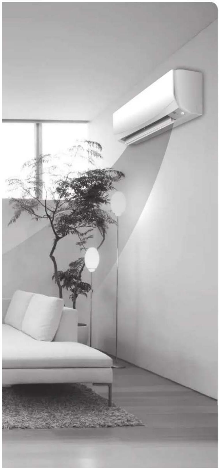
Modern minimalist living room interior with white sofa, wall-mounted air conditioner unit, and potted plant (no text or symbols visible)
ECONO
This function enables efficient operation by limiting the maximum power consumption. It is useful when using the air conditioner and other electrical devices simultaneously on a shared electrical circuit. ▶Page 18
Contents
Read Before Operation
Safety Precautions 3
Names of Parts 5
Preparation Before Operation 9
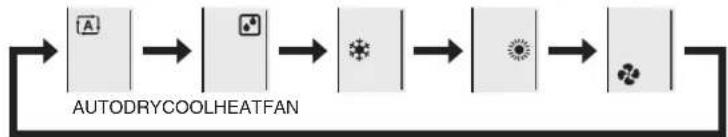
Basic Operation

AUTO · DRY · COOL · HEAT · FAN Operation ....11

Adjusting the Airflow Rate .....12

Adjusting the Airflow Direction .....13
Useful Functions

COMFORT AIRFLOW Operation .....14

INTELLIGENT EYE Operation .....15

POWERFUL Operation ......17

ECONO / OUTDOOR UNIT QUIET Operation 18
TIMER Operation

ON/OFF TIMER Operation .....19

WEEKLY TIMER Operation ......22
Care
Care and Cleaning 28
When the Need Arises
FAQ 32
Troubleshooting 33
Safety Precautions
Read the precautions in this manual carefully before operating the unit.

This appliance is filled with R32.
- Keep this manual where the user can easily find it.
- The precautions described herein are classified as WARNING and CAUTION. They both contain important information regarding safety. Be sure to observe all precautions without fail.

WARNING
Failure to follow these instructions properly may result in personal injury or loss of life.

CAUTION
Failure to observe these instructions properly may result in property damage or personal injury, which may be serious depending on the circumstances.

Never attempt.

Be sure to follow the instructions.

Be sure to establish an earth connection.
- After reading, keep this manual in a convenient place so that you can refer to it whenever necessary. If the equipment is transferred to a new user, be sure also to hand over the manual.

WARNING

- Do not use means to accelerate the defrosting process or to clean, other than those recommended by the manufacturer.
- The appliance must be stored in a room without continuously operating ignition sources (for example: open flames, an operating gas appliance or an operating electric heater).
- Do not pierce or burn.
- Be aware that refrigerants may not contain an odour.
- The appliance must be installed, operated and stored in a room with floor area larger than -^*m^2 for 20/25/35/46 class.
* Since the maximum refrigerant charge of the models is below 1.84kg, it does not have any limitation for the minimum floor area. Maintain an installation height of 1.8m or more from the floor surface to the bottom of the appliance. If the size of the room where the appliance is to be installed has less than the indicated minimum floor area, install it in a well ventilated room. For details refer to the WARNING list in the "Safety Precautions" section of the installation manual for the outdoor unit.
• To avoid fire, explosion or injury, do not operate the unit when harmful gases (e.g. flammable or corrosive) are detected near the unit. - Be aware that prolonged, direct exposure to cool or warm air from the air conditioner, or to air that is too cool or too warm, can be harmful to your physical condition and health.
- Do not place objects, including rods, your fingers, etc., in the air inlet or outlet. Product damage or personal injury may result due to contact with the air conditioner's high-speed fan blades.
- Do not attempt to repair, dismantle, reinstall or modify the air conditioner yourself as this may result in water leakage, electric shock or fire hazards.
- Do not use flammable spray near the air conditioner, or otherwise fire may result.
- Do not use a refrigerant other than the one indicated on the outdoor unit (R32) when installing, moving or repairing. Using other refrigerants may cause trouble or damage to the unit, and personal injury.
• To avoid electric shock, do not operate with wet hands.

- Beware of fire in case of refrigerant leakage. If the air conditioner is not operating correctly, i.e. not generating cool or warm air, refrigerant leakage could be the cause. Consult your dealer for assistance. The refrigerant within the air conditioner is safe and normally does not leak. However, in the event of a leakage, contact with a naked burner, heater or cooker may result in generation of noxious gas. Do not use the air conditioner until a qualified service person confirms that the leakage has been repaired.
- Do not attempt to install or repair the air conditioner yourself. Improper workmanship may result in water leakage, electric shock or fire hazards. Please contact your local dealer or qualified personnel for installation and maintenance work.
- If the air conditioner is malfunctioning (giving off a burning odour, etc.), turn off power to the unit and contact your local dealer. Continued operation under such circumstances may result in a failure, electric shock or fire hazards.
- Be sure to install an earth leakage circuit breaker. Failure to install an earth leakage circuit breaker may result in electric shock or fire.

- Be sure to earth the unit. Do not earth the unit to a utility pipe, lightning conductor or telephone earth lead. Imperfect earthing may result in electric shock.

CAUTION

- Do not use the air conditioner for purposes other than those for which it is intended. Do not use the air conditioner for cooling precision instruments, food, plants, animals or works of art as this may adversely affect the performance, quality and/or longevity of the object concerned.
- Do not expose plants or animals directly to the airflow from the unit as this may cause adverse effects.
- Do not place appliances that produce naked flames in places exposed to the airflow from the unit as this may impair combustion of the burner.
- Do not block the air inlets nor outlets. Impaired airflow may result in insufficient performance or trouble.

- Do not sit on the outdoor unit, put things on the unit, or pull the unit. Doing so may cause accidents, such as falling or toppling down, thus resulting in injury, product malfunctioning, or product damage.
- Do not place objects that are susceptible to moisture directly beneath the indoor or outdoor units. Under certain conditions, condensation on the main unit or refrigerant pipes, air filter dirt or drain blockage may cause dripping, resulting in fouling or failure of the object concerned.
- After prolonged use, check the unit stand and its mounts for damage. If they are left in a damaged condition, the unit may fall and cause injury.
- To avoid injury, do not touch the air inlet or aluminium fins of the indoor or outdoor units.
- The appliance is not intended for use by unattended young children or infirm persons. Impairment of bodily functions and harm to health may result.
- Children should be supervised to ensure that they do not play with the unit or its remote controller. Accidental operation by a child may result in impairment of bodily functions and harm health.
- Avoid impacts to the indoor and outdoor units, or otherwise product damage may result.
- Do not place flammable items, such as spray cans, within 1m of the air outlet.
The spray cans may explode as a result of hot air from the indoor or outdoor units. - Be careful not to let pets urinate on the air conditioner. Urination on the air conditioner may result in electric shock or fire.
- Do not wash the air conditioner with water, as this may result in electric shock or fire.
- Do not place water containers (vases, etc.) above the unit, as this may result in electric shock or fire hazards if they should topple over.
- Do not insert the batteries in the wrong polarity (+/-) orientation as this may result in short circuiting, fire, or battery leakage.
- Do not sit or hang on the panel. The panel may fall, and injury or product malfunctioning may result.
- Do not sway the panel. The panel may hit people or objects, and injury or property damage may result.
- Do not let children play around the panel. Injury or property damage may result.
- Do not pull the wires. The wires may be broken and the panel may fall, and injury or property damage may result.
- Do not locate obstacles in the route. The panel may fall, and injury or property damage may result.
- Do not bend or damage the wires. The wires may be broken and the panel may fall, and injury or property damage may result.
- Do not put objects on the panel, or otherwise production malfunctioning may result.
- Do not use an unstable stand at the time of operating or maintaining the air conditioner, or otherwise you may topple over or injury yourself.
- Locate the remote controller in places out of reach of children. The wrong operation of the remote controller may result in injury.

- To avoid oxygen depletion, ensure that the room is adequately ventilated if equipment such as a burner is used together with the air conditioner.
- Before cleaning, be sure to stop unit operation and turn off the circuit breaker. Otherwise, an electric shock and injury may result.
- Only connect the air conditioner to the specified power supply circuit. Power supplies other than the one specified may result in electric shock, overheating and fires.
- Arrange the drain hose to ensure smooth drainage. Imperfect drainage may cause wetting of the building, furniture, etc.
- Do not place objects in direct proximity of the outdoor unit and do not let leaves and other debris accumulate around the unit. Leaves are a hotbed for small animals which can enter the unit. Once inside the unit, such animals can cause malfunctions, smoke or fire if they come into contact with electrical parts.
- Do not place objects around the indoor unit.
Doing so may have an adverse influence on the performance, product quality, and life of the air conditioner. - This appliance is not intended to be used by persons with reduced physical, sensory or mental capabilities, or with lack of operation knowledge, unless they have been given supervision or instruction concerning the appliance use by person responsible for their safety. Keep out of children's reach to ensure that they do not play with the appliance.
Precautions relating to area surrounding the indoor and outdoor units
■ Be sure to follow the instructions below.
- The indoor unit is at least 1m away from any television or radio set (unit may cause interference with the picture or sound).
- Refrain from using the units in areas prone to high levels of oily smoke, such as a kitchen. Water leakage may result.
Names of Parts
Indoor Unit

text_image
Front panel Air inlet Flap (horizontal blade) ▶Page 13 Louvres (vertical blades) • The louvres are inside of the air outlet. ▶Page 13 Air outlet Model name INTELLIGENT EYE sensor • Detects the movements of people and automatically switches between normal operation and energy saving operation. ▶Page 15,16 Room temperature sensor • Detects the air temperature around the unit.Display
Signal receiver
- Receives signals from the remote controller.
- When the unit receives a signal, you will hear a beep sound.
| Case Sound type |
| Operation start beep-beep |
| Setting changed beep |
| Operation stop long beep |
text_image
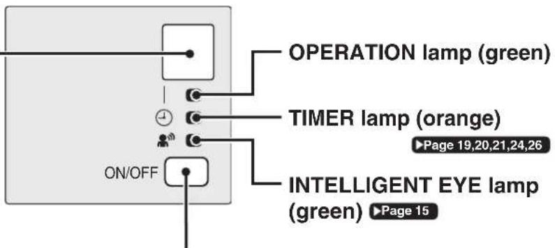
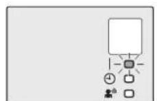
OPERATION lamp (green) TIMER lamp (orange) ON/OFF ►Page 19,20,21,24,26 INTELLIGENT EYE lamp (green) ►Page 15Indoor unit ON/OFF switch
- Press this switch once to start operation. Press once again to stop it.
- For the operation mode setting, refer to the following table.
| Mode Temperature setting Airflow rate | |
| AUTO 25.0°C AUTO | |
- This switch can be used when the remote controller is missing or out of batteries.
■ Open the front panel

text_image
Deodorizing filter (enzyme blue) Air filterOutdoor Unit
■ For 20/25/35 class
text_image
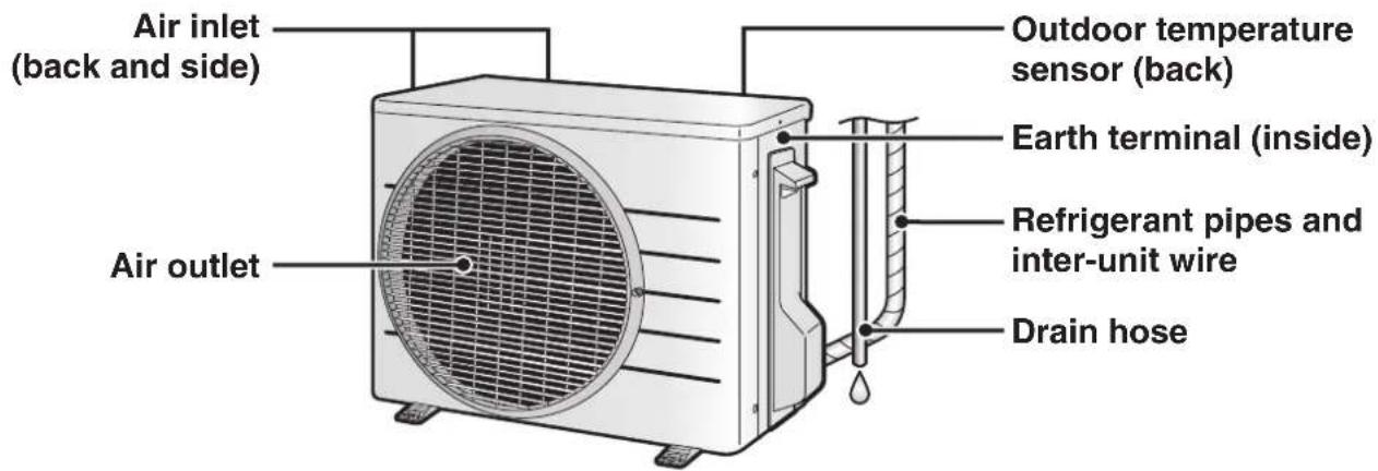
Air inlet (back and side) Outdoor temperature sensor (back) Air outlet Earth terminal (inside) Refrigerant pipes and inter-unit wire Drain hoseFor 46 class

text_image
Air inlet (back and side) Outdoor temperature sensor (back) Refrigerant pipes and inter-unit wire Earth terminal (inside) Drain hose Air outletNames of Parts
Remote Controller

text_image
Signal transmitter Receiver To use the remote controller, aim the transmitter at the indoor unit. If there is anything blocking the signals between the unit and the remote controller, such as a curtain, the unit may not operate. The maximum transmission distance is about 7m. Display (LCD) • Displays the current settings. (In this illustration, each section is shown with all its displays on for the purpose of explanation.) TEMPERATURE adjustment button • Changes the temperature setting. ▶Page 11 FAN setting button • Selects the airflow rate setting. ▶Page 12 POWERFUL button • POWERFUL operation. ▶Page 17 ON/OFF button • Press this button once to start operation. Press once again to stop it. ▶Page 11 Front cover • Open the front cover. ▶Page 8 Model name ARC466A26■ Open the front cover
text_image
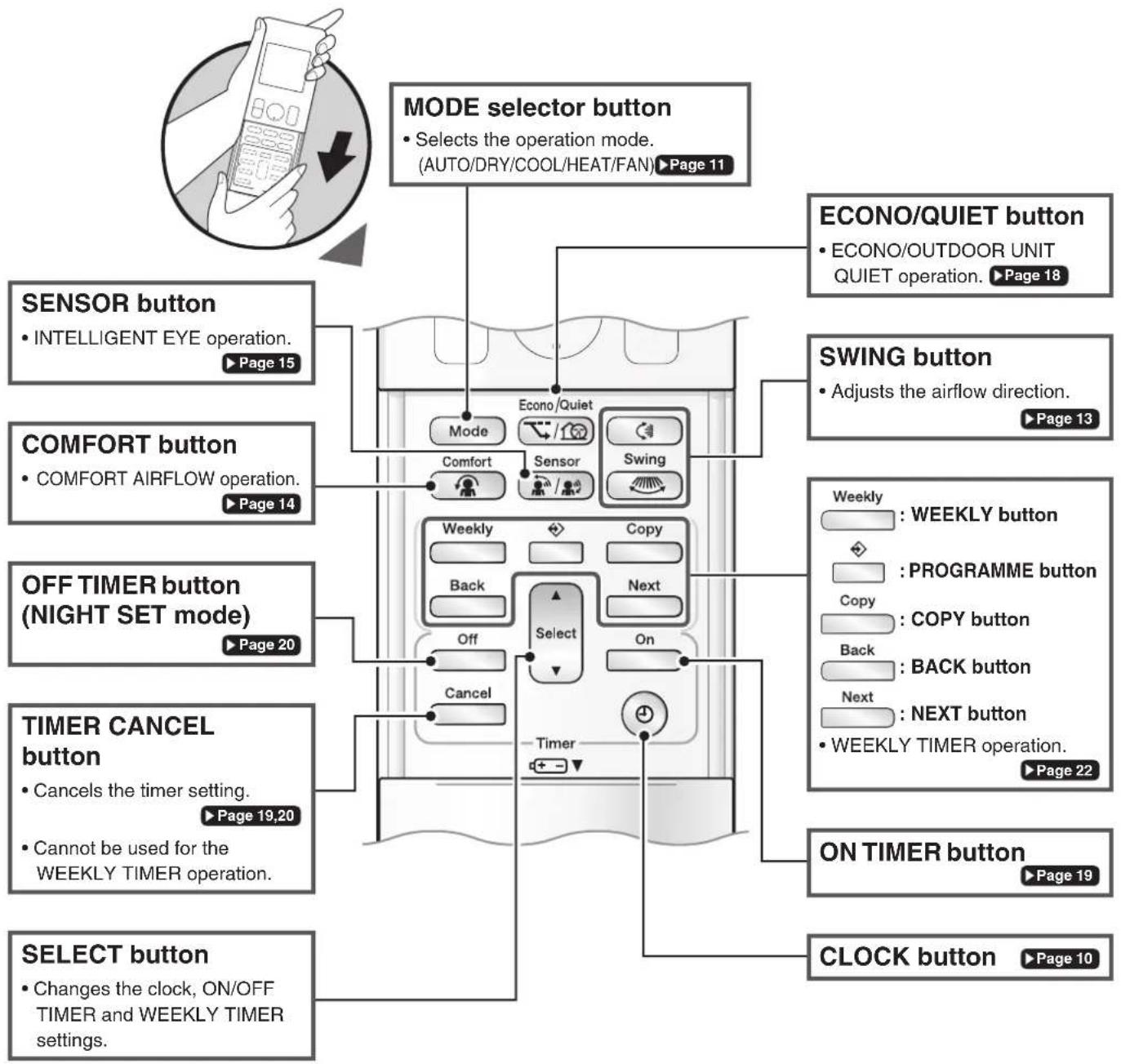
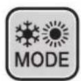
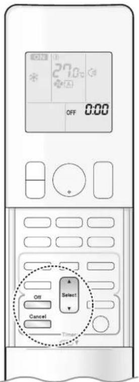
MODE selector button • Selects the operation mode. (AUTO/DRY/COOL/HEAT/FAN) ▶ Page 11 ECONO/QUIET button • ECONO/OUTDOOR UNIT QUIET operation. ▶ Page 18 SENSOR button • INTELLIGENT EYE operation. ▶ Page 15 COMFORT button • COMFORT AIRFLOW operation. ▶ Page 14 OFF TIMER button (NIGHT SET mode) ▶ Page 20 TIMER CANCEL button • Cancels the timer setting. ▶ Page 19,20 • Cannot be used for the WEEKLY TIMER operation. SELECT button • Changes the clock, ON/OFF TIMER and WEEKLY TIMER settings.Preparation Before Operation

CAUTION
Incorrect handling of batteries can result in injury from battery leakage, rupturing or heating, or lead to equipment failure.
Please observe the following precautions and use safely.
- If the alkaline solution from the batteries should get in the eyes, do not rub the eyes. Instead, immediately flush the eyes with tap water and seek the attention of a medical professional.
- Keep batteries out of reach of children. In the event that batteries are swallowed, seek the immediate attention of a medical professional.
- Do not expose batteries to heat or fire. Do not disassemble or modify batteries. The insulation or gas release vent inside the battery may be damaged, resulting in battery leakage, rupturing, or heating.
- Do not damage or peel off labels on the batteries.
■ To insert the batteries
- Slide the front cover to take it off.
- Insert 2 dry batteries AAA.LR03 (alkaline).
- Replace the front cover.
■ To fix the remote controller holder to a wall
- Choose a place from where the signals reach the unit.
- Fix the holder to a wall, a pillar, or similar location with the screws supplied with the holder.
- Place the remote controller in the remote controller holder.
■ To attach the deodorizing filter (enzyme blue)
- If attaching the separately sold filters, attach them before turning the power on.
■ Turn on the circuit breaker
• After the power is turned on, the flap of the indoor unit opens and closes once to set the reference position.

text_image
1 2 3 Position + and - correctly!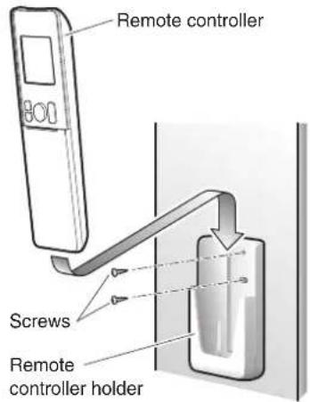
text_image
Remote controller Screws Remote controller holderNOTE
Notes on batteries
- To avoid possible injury or damage from battery leakage or rupturing, remove the batteries when not using the product for long periods of time.
- The standard replacement time is 1 year. Both batteries should be replaced at the same time. Be sure to replace them with new size AAA. LR03 (alkaline) batteries.
- When battery power has run out, the LCD will begin blinking as an alert that the batteries need replacing. In some cases, when battery consumption is accelerated owing usage conditions, signal reception may decline before the LCD begins blinking.
- The batteries supplied with the remote controller are for initial operation. The batteries may run out in less than 1 year.
Note on remote controller
- Do not drop the remote controller. Do not get it wet.

text_image
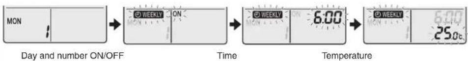
MON 15:30 27.0 Select Timer■ To set the clock
1. Press
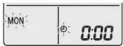
" 0.00 appears on the LCD.
"MON" and "💡 blink.
2. Press to set the current day of the week.
3. Press

" blinks.
4. Press to set the clock to the present time.
- Holding down ▲ or rapidly increases or decreases the displayed time.
5. Press ⏰
- Point the remote controller at the indoor unit when pressing the buttons.

“*” blinks.
NOTE
Note on setting the clock
- If the indoor unit's internal clock is not set to the correct time, the ON/OFF TIMER and WEEKLY TIMER will not operate punctually.
text_image
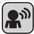
ON 27.0°C * A MON 15:30 On/Off Temp Mode TimerThe air conditioner operates with the operation mode of your choice.
From the next time on, the air conditioner will operate with the same operation mode.
■ To start
1. Press and select an operation mode.
• Each pressing of the button changes the mode setting in sequence.
flowchart
graph LR
    A["Input"] --> B["Process Step 1"]
    B --> C["Process Step 2"]
    C --> D["Process Step 3"]
    D --> E["Output"]
2. Press On/Off
• " Off pears on the LCD.
• The OPERATION lamp lights green.
Display
■ To stop
Press again.
• " ON appears from the LCD.
• The OPERATION lamp goes off.
■ To change the temperature setting
Press

- Press ▲ to raise the temperature and press ▼ to lower the temperature.
Each pressing of the button changes the temperature by 0.5^ C.
| COOL operation | HEAT operation | AUTO operation | DRY or FAN operation |
| 18.0-32.0°C | 10.0-30.0°C | 18.0-30.0°C | The temperature setting cannot be changed. |
NOTE
Notes on AUTO operation
- In AUTO operation, the system selects an appropriate operation mode (COOL or HEAT) based on the indoor temperature, then starts the operation.
- The system automatically reselects setting at a regular interval to bring the indoor temperature to user-setting level.
Note on COOL operation
- This air conditioner cools the room by releasing the heat in the room outside.
Therefore, the cooling performance of the air conditioner may be degraded if the outdoor temperature is high.
Note on DRY operation
- Eliminates humidity while maintaining the indoor temperature as much as possible. It automatically controls temperature and airflow rate, so manual adjustment of these functions is unavailable.
Notes on HEAT operation
- Since this air conditioner heats the room by taking heat from outdoor air to indoors, the heating capacity becomes smaller in lower outdoor temperatures. If the heating effect is insufficient, it is recommended to use another heating appliance in combination with the air conditioner.
- The heat pump system heats the room by circulating hot air around all parts of the room. After the start of HEAT operation, it takes some time before the room gets warmer.
- In HEAT operation, frost may occur on the outdoor unit and lower the heating capacity. In that case, the system switches into defrosting operation to take away the frost.
Note on FAN operation
• This mode is valid for fan only.

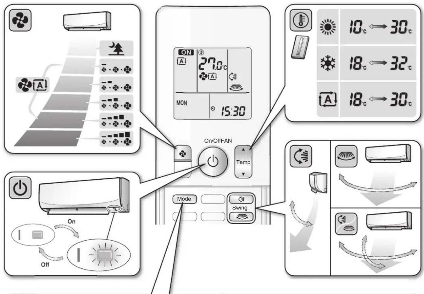
Adjusting the Airflow Rate

text_image
27.0°C MON 15:30 FanYou can adjust the airflow rate to increase your comfort.
■ To adjust the airflow rate setting

• Each pressing of the button changes the airflow rate setting in sequence.

flowchart
graph LR
    A["AUTO Indoor unit quiet Airflow rate 1-5 (Low to High)"] --> B["..."]
    B --> C["..."]
    C --> D["..."]
    D --> E["..."]
    E --> F["..."]
    F --> G["..."]
    G --> H["..."]
    H --> I["..."]
    I --> J["..."]
    J --> K["..."]
    K --> L["..."]
    L --> M["..."]
    M --> N["..."]
    N --> O["..."]
    O --> P["..."]
    P --> Q["..."]
    Q --> R["..."]
    R --> S["..."]
    S --> T["..."]
    T --> U["..."]
    U --> V["..."]
    V --> W["..."]
    W --> X["..."]
    X --> Y["..."]
    Y --> Z["..."]
    Z --> A
- When the airflow is set to “quiet operation starts and noise from the indoor unit will become quieter.
- In the quiet operation mode, the airflow rate is set to a weak level.
- In DRY operation, the airflow rate setting cannot be changed.
- At smaller airflow rates, the cooling (heating) effect is also smaller.
Tips for saving energy
Keeping the temperature setting at a moderate level helps save energy.
- Recommended temperature setting for cooling: 26.0-28.0°C, for heating: 20.0-24.0°C
Cover windows with a blind or a curtain.
- Blocking sunlight and air from outdoors increases the cooling (heating) effect.
Keep the air filters clean.
• Clogged air filters cause inefficient operation and waste energy. Clean them once in about every 2 weeks. ▶ Page 29
If you are not going to use the air conditioner for a long period, for example in spring or autumn, turn off the circuit breaker.
- The air conditioner always consumes a small amount of electricity even while it is not operating.

Adjusting the Airflow Direction
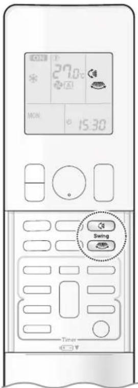
text_image
27.0°C MON 15:30 Swing TimerYou can adjust the airflow direction to increase your comfort.
ATTENTION
• Always use a remote controller to adjust the angles of the flap and louvres.
- If you attempt to move the flap and louvres forcibly by hand when they are swinging, the mechanism may be damaged.
- Inside the air outlet, a fan is rotating at a high speed.
■ To start auto swing
Up and down airflow direction
Press
• “ Appears on the LCD.
• The flap (horizontal blade) will begin to swing.
Right and left airflow direction
Press
• “ appears on the LCD.
- The louvres (vertical blades) will begin to swing.
The 3-D airflow direction
Press and .
• “ and ” appear on the LCD.
• The flap and louvres move in turn.
- To cancel 3-D airflow, press either 📁 or again.
The flap or louvres will stop moving.

natural_image
Diagram showing a circular icon with rotation arrows and a rectangular device emitting motion (no text or symbols)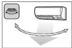
text_image
Diagram illustrating airflow or fluid flow with a pipe and a cylinder, showing directional arrows and a schematic symbol.
natural_image
Diagram showing airflow around a vehicle with curved arrows indicating direction (no text or symbols)■ To set the flap or louvres at the desired position
- This function is effective while the flap or louvres are in auto swing mode.
Press and when the flap or louvres reach the desired position.
• In the 3-D airflow, the flap and louvres move in turn.
- “ 📋” or “ 📄” disappears from the LCD.
NOTE
Note on airflow direction setting
- The movable range of the flap varies according to the operation mode.
Note on 3-D airflow
- Using 3-D airflow circulates cold air, which tends to collect at the bottom of the room, and hot air, which tends to collect near the ceiling, throughout the room, preventing areas of cold and hot developing.
Movable range of the flap

text_image
e of the flap COOL / DRY FAN HEAT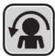
COMFORT AIRFLOW Operation

text_image
27.0°C MUN 15:30 Comfort TimerThe flow of air will be in the upward direction while in COOL operation and in the downward direction while in HEAT operation, which will provide a comfortable wind that will not come in direct contact with people.

natural_image
Diagram of a airflow or ventilation system with a duct and fan (no text or symbols)COOL operation

natural_image
Pure diagram of a curved pipe or duct with no text, numbers, or symbolsHEAT operation
■ To start

Press
Comfort

• “ 🙏 appears on the LCD.
| COOL and DRY operation | HEAT operation FAN | operation | |
| Flap direction | Goes up Goes down | Not available | |
| Airflow rate AUTO | |||
■ To cancel

Press
Comfort

again.
• “ disappears from the LCD.
- The flap will return to the position in memory from before COMFORT AIRFLOW operatoin.
NOTE
Notes on COMFORT AIRFLOW Operation
- The flap position will change, preventing air from blowing directly on the occupants of the room.
- POWERFUL operation and COMFORT AIRFLOW operation cannot be used at the same time.
• The airflow rate will be set to AUTO. - If the upward and downward airflow direction is selected, the COMFORT AIRFLOW function will be canceled.
Priority is given to the function of whichever button is pressed last.

INTELLIGENT EYE Operation
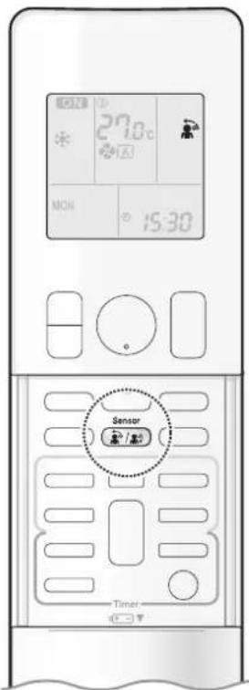
text_image
27.0°C MON 15:30 Sensor TimerThe INTELLIGENT EYE sensor detects human movement and adjusts airflow direction. It can be set to avoid people or to direct airflow specifically at people. If no one is in the room for more than 20 minutes, the operation automatically changes to energy saving operation.

CAUTION
- Do not place large objects near the INTELLIGENT EYE sensor. Also keep heating units and humidifiers outside the sensor's detection area. This sensor can detect undesirable objects.
- Do not hit or violently push the INTELLIGENT EYE sensor. This can lead to damage and malfunction.
■ To start
Press sensor and select the desired mode.
• Each time the button is pressed, a different setting option appears on the LCD.
• The INTELLIGENT EYE lamp lights green.

text_image
Display
flowchart
graph LR
    A["Directly on people"] --> B["Blow directly on people"]
    B --> C["blank\nNo Setting Do not blow"]
- When the flap (horizontal blade) is swinging, selecting any of the modes above will cause the flap (horizontal blade) to stop.
- The lamp lights when human movement is detected.
■ To cancel
Press Sensor until no icon is displayed.
• The INTELLIGENT EYE lamp goes off.
NOTE
Note on INTELLIGENT EYE operation
- INTELLIGENT EYE operation is set to blow directly on people, the air conditioner tracks you horizontally, without the air blowing directly on you.
- When the INTELLIGENT EYE sensor detects the movement of people, it adjusts the airflow direction upward (while in COOL operation) and downward (while in HEAT operation), by adjusting the flap. Depending on the setting, the louvres (vertical blades) will either direct airflow directly toward or away from people.
■ How the INTELLIGENT EYE operation works
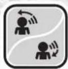
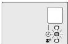
The INTELLIGENT EYE sensor detects human movement and adjusts the right and left airflow direction. If no one is in the room for more than 20 minutes, the operation automatically changes to energy saving operation. The INTELLIGENT EYE sensor works differently depending on the situation.
[Example]
| A person is detected in area 1. area 2. | A person is detected in | People are detected in both areas. | No people are detected in the areas. | |
 | 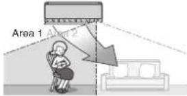 |  | The airflow is directed to Area 1. | 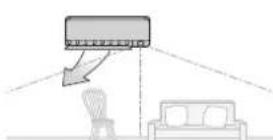 |
 |  | 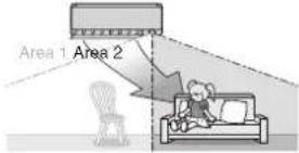 | The current airflow direction is maintained. | The air conditioner will switch to energy-saving mode after 20 minutes. |
* The airflow direction may differ from the illustrated direction depending on the actions and movements of the people in the areas.
INTELLIGENT EYE operation is useful for energy saving
Energy saving operation
- If no presence detected in the room for 20 minutes, the energy saving operation will start, and the INTELLIGENT EYE lamp goes off. If human movement is detected again, the INTELLIGENT EYE lamp lights up and energy saving operation terminates.
- This operation changes the temperature by -2^ in HEAT / +2^ in COOL / +2^ in DRY operation from the set temperature. When the room temperature exceeds 30^ , the operation changes the temperature by +1^ in COOL / +1^ in DRY operation from the set temperature.
- This operation decreases the airflow rate slightly in FAN operation only.
NOTE
Notes on INTELLIGENT EYE operation
• Application range is as follows.

text_image
Vertical angle 90° (Side view) 5m 90°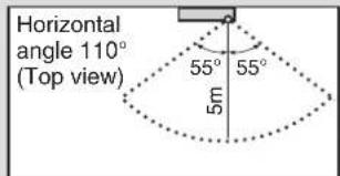
text_image
Horizontal angle 110° (Top view) 55° 55° 5m- While the air conditioner is in INTELLIGENT EYE operation, the louvres adjust the airflow direction if there are people in the sensing areas of the INTELLIGENT EYE so that the leftward or rightward airflow will not be directed to the people. If no people are detected in either area 1 or 2 for 20 minutes, the air conditioner switches to the energy-saving mode with the set temperature shifted by 2^ .
The air conditioner may switch to the energy-saving operation even if there are people in the areas.
This may occur depending on the clothes the people are wearing, if there is no movement of the people in the areas.
- The airflow direction from the louvres will be leftward if there are people in both areas 1 and 2. The air will also flow left if there is a person right in front of the sensor as the sensor judges that there are people in both areas.
- Due to the position of the sensor, people might be exposed to the airflow of the indoor unit if they are close to the front side of the indoor unit. If there are people close to the front side of the indoor unit or in both areas, it is recommended to use the COMFORT AIRFLOW and INTELLIGENT EYE operations simultaneously. Using both modes together, the air conditioner will not direct the airflow towards the people.
• The sensor could also mistakenly detect pets, sunlight, fluttering curtains and light reflected off of mirrors as passers-by. - The sensor may not detect moving objects further than 5m away. (Please see the application range)
- Sensor detection sensitivity changes according to the indoor unit location, the speed of passers-by, temperature range, etc.
- NIGHT SET mode ▶Page 20 will not switch on during use of INTELLIGENT EYE operation.

POWERFUL Operation
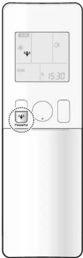
text_image
15:30 PowerfulPOWERFUL operation quickly maximises the cooling (heating) effect in any operation mode. In this mode, the air conditioner operates at maximum capacity.
■ To start
Press during operation.
• “ appears on the LCD.
- POWERFUL operation ends in 20 minutes. Then the system automatically operates again with the previous settings which were used before POWERFUL operation.
■ To cancel
Press again.
• “ disappears from the LCD.
NOTE
Notes on POWERFUL operation
- Pressing causes the settings to be cancelled, and " " disappears from the LCD.
- POWERFUL operation will not increase the capacity of the air conditioner if the air conditioner is already in operation with its maximum capacity demonstrated.
- In COOL, HEAT and AUTO operation
To maximise the cooling (heating) effect, the capacity of outdoor unit increases and the airflow rate becomes fixed at the maximum setting. The temperature and airflow settings cannot be changed. - In DRY operation
The temperature setting is lowered by 2.5°C and the airflow rate is slightly increased. - In FAN operation
The airflow rate is fixed at the maximum setting.
Regarding the combination of POWERFUL and other operations
| POWERFUL + COMFORT AIRFLOW | Not available* |
| POWERFUL + ECONO | |
| POWERFUL + OUTDOOR UNIT QUIET |
*Priority is given to the function of whichever button is pressed last.

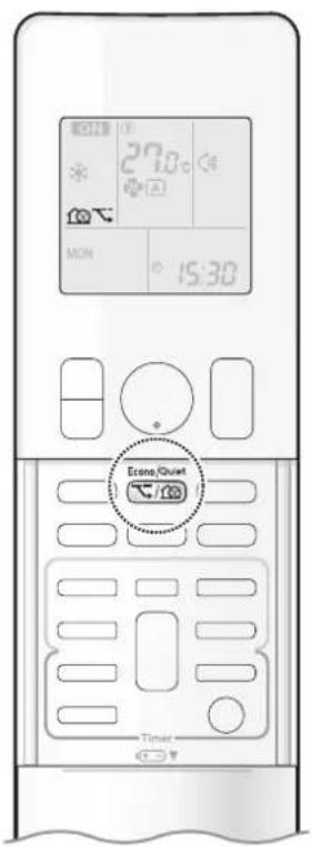
ECONO / OUTDOOR UNIT QUIET Operation
text_image
27.0 MON 15:30 Ezone Chout TieterECONO operation enables efficient operation by limiting the maximum power consumption. This function is useful to prevent the circuit breaker from tripping when the unit operates alongside other appliances on the same circuit.
OUTDOOR UNIT QUIET operation lowers the noise level of the outdoor unit by changing the frequency and fan speed of the outdoor unit. This function is convenient during the night-time operation.
■ To start
Press Econo/Quiet and select the desired mode.
• Each time the button is pressed, a different setting option appears on the LCD.
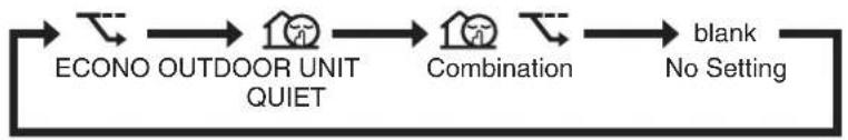
flowchart
graph LR
    A["ECONO OUTDOOR UNIT QUIET"] --> B["Combination"]
    B --> C["blank\nNo Setting"]
■ To cancel
Press Econo/Quiet until no icon is displayed.
NOTE
Notes on ECONO operation
- This operation is performed with lower power and therefore may not provide a sufficient cooling (heating) effect.
- Pressing ⏻ causes the settings to be cancelled, and “” disappears from the LCD.
- If the power consumption level is already low, switching to ECONO operation will not reduce the power consumption.
Notes on OUTDOOR UNIT QUIET operation
- Even if the operation is stopped by using the remote controller or the indoor unit ON/OFF switch when using OUTDOOR UNIT QUIET operation, "💡" will remain displayed on the remote controller.
- OUTDOOR UNIT QUIET operation will not reduce the frequency nor fan speed if they already are operating at reduced levels.
- This operation is performed with lower power and therefore may not provide a sufficient cooling (heating) effect.
Possible combinations of ECONO / OUTDOOR UNIT QUIET operation and basic operations
| Operation mode | ||||
| DRY COOL | HEAT FAN | |||
| ECONO | √ | √ | √ | - |
| OUTDOOR UNIT QUIET | - | √ | √ | - |

ON/OFF TIMER Operation

text_image
27.0 ON 6:00 Select Cancel On TimerTimer functions are useful for automatically switching the air conditioner on or off at night or in the morning. You can also use the ON TIMER and OFF TIMER together.
[ON TIMER with a 24 hour clock display] (24 HOUR ON/OFF TIMER)
■ To set
- Check that the clock is correct.
If not, set the clock to the present time. ▶Page 10
1. Press On
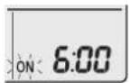
“5.00 appears on the LCD.
"ON" blinks.
- “④” and day of the week disappear from the LCD.
2. Press until the time setting reaches the point you like.
- Each pressing of either button increases or decreases the time setting by 10 minutes. Holding down either button changes the setting rapidly.
3. Press on again.
- “ON” and setting time appear on the LCD.
• The TIMER lamp lights orange.
Display
■ To cancel
Press Cancel.
- “ON” and setting time disappear from the LCD.
- “ ⊕” and day of the week appear on the LCD.
• The TIMER lamp goes off.
NOTE
Note on TIMER operation
- When TIMER is set, the present time is not displayed.
In the following cases, set the timer again.
• After the circuit breaker has turned off.
• After a power failure.
• After replacing the batteries in the remote controller.
text_image
27.0 OFF 0:00 Off Select Cancel Timer[OFF TIMER with a 24 hour clock display] (24 HOUR ON/OFF TIMER)
■ To set
- Check that the clock is correct. If not, set the clock to the present time. ▶Page 10
1. Press Off

"0:appears on the LCD. "OFF" blinks.
- “ ⊕” and day of the week disappear from the LCD.
2. Press until the time setting reaches the point you like.
• Each pressing of either button increases or decreases the time setting by 10 minutes. Holding down either button changes the time setting rapidly.
3. Press again.
- “OF and setting time appear on the LCD. - The TIMER lamp lights orange.
Display
■ To cancel
Press Cancel.
- “OF and setting time disappear from the LCD.
- “ ⏻” and day of the week appear on the LCD.
• The TIMER lamp goes off.
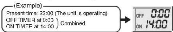
[ON/OFF TIMER combination]
■ To combine
- A sample setting for combining the 2 timers is shown below.
text_image
(Example) Present time: 23:00 (The unit is operating) OFF TIMER at 0:00 ON TIMER at 14:00) Combined OFF 0:00 ON 14:00NOTE
NIGHT SET mode
- When the OFF TIMER is set, the air conditioner automatically adjusts the temperature setting (0.5°C up in COOL, 2.0°C down in HEAT) to prevent excessive cooling (heating) during sleeping hours.

ON/OFF TIMER Operation

text_image
27.0°C ON Ihr Off Select On Cancel Timer[ON/OFF TIMER with an hours remaining display] (COUNT UP-DOWN ON/OFF TIMER)
- Check that the clock is correct. If not, set the clock to the present time. ▶Page 10
1. Press and hold on or for about 5 seconds, when signal indicator (▲) blink, release your finger from the button.
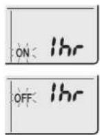
For ON TIMER
"Ibr" appears on the LCD.
"ON" blinks.
For OFF TIMER
"Ihr" appears on the LCD.
"OFF" blinks.
- “ ⊕” and day of the week disappear from the LCD.
2. Press until the time setting reaches the point you like.
• Each pressing of the button increases or decreases the time setting by 1 hour.
• The time can be set between 1 and 12 hours.
3. Press on or again.
- “ONand” “OFF and setting time appear on the LCD.
• The TIMER lamp lights orange.
- To change the display mode from COUNT UP-DOWN ON/OFF TIMER to 24 HOUR ON/OFF TIMER, repeat STEP 1, and continue from STEP 2 of "24 HOUR ON/OFF TIMER". ▶ Page 19, 20
- Timer display mode cannot be changed while "ON" or "OFF" are blinking. Press ☐ or ☐ to stop the blinking.

Display
■ Combining display modes
- Different display modes (24 HOUR ON/OFF TIMER and COUNT UP-DOWN ON/OFF TIMER) can be used for the ON TIMER and OFF TIMER simultaneously.
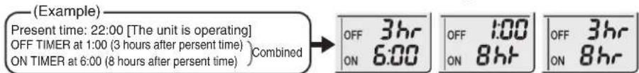
text_image
(Example) Present time: 22:00 [The unit is operating] OFF TIMER at 1:00 (3 hours after persent time) ON TIMER at 6:00 (8 hours after persent time) )Combined OFF 3hr ON 6:00 OFF 1:00 ON 8hr OFF 3hr ON 8hrNOTE
Note on COUNT UP-DOWN ON/OFF TIMER
- After setting, the time displayed on the LCD will automatically count down by 1 hour for every 1 hour that passes. For example, if the OFF TIMER is set to 3 hours, the display will change as follows: 3hr 2hr 1hr blank (OFF)
Switching between ON/OFF TIMER display modes (24 hour clock and hours remaining display)
- When changing timer display modes (from 24 HOUR ON/OFF TIMER to COUNT UP-DOWN ON/OFF TIMER or vice versa), the timer cancels. The timer must be set again to activate it.
WEEKLY TIMER Operation
Up to 4 timer settings can be saved for each day of the week. This is convenient to adapt the WEEKLY TIMER to your family's life style.
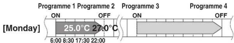
■ Setting example of the WEEKLY TIMER
The same timer settings are used from Monday through Friday, while different timer settings are used for the weekend.
| [Monday] | Make timer settings for programmes 1-4. ▶Page 23 | |||
| Programme 1 | Programme 2 | Programme 3 | Programme 4 | |
 |  |  |  | |
| [Tuesday] to [Friday] | Use the copy mode to make settings for Tuesday to Friday, because these settings are the same as those for Monday. ▶Page 25Pr | 4 | ||
| [Saturday] | No timer settings | |||
| [Sunday] | Make timer settings for programmes 1-4. ▶Page 23 | |||
- Up to 4 reservations per day and 28 reservations per week can be set using the WEEKLY TIMER. The effective use of the copy mode simplifies timer programming.
- The use of ON-ON-ON-ON settings, for example, makes it possible to schedule operating mode and set temperature changes. Furthermore, by using OFF-OFF-OFF-OFF settings, only the turn off time of each day can be set. This will turn off the air conditioner automatically if you forget to turn it off.

WEEKLY TIMER Operation
text_image
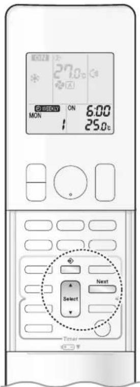
MOZZER 27.0°C ON MON 6:00 25.0°C Select Next Timer■ To use WEEKLY TIMER operation
Setting mode
- Make sure the day of the week and time are set. If not, set the day of the week and time. ▶Page 10
text_image
[Monday] Programme 1 Programme 2 ON OFF Programme 3 6:00 8:30 17:30 22:00 25.0°C 27.0°C Programme 4 ON OFFSetting Displays
flowchart
graph LR
    A["MON"] --> B["ON"]
    B --> C["6:00"]
    C --> D["25.0°C"]
1. Press
- The day of the week and the reservation number of the current day will be displayed. - 1 to 4 settings can be made per day.
2. Press Select to select the desired day of the week and reservation number.
- Pressing Select changes the reservation number and the day of the week.
3. Press Next .
- The day of the week and reservation number will be set. - “WEEKLY” and “ON” blink.
4. Press Select to select the desired mode.
- Pressing Select changes the "ON" or "OFF" setting in sequence.

flowchart
graph LR
    A["ON"] --> B["OFF"]
    B --> C["blank"]
    D["ON TIMER"] --> A
    E["OFF TIMER"] --> B
    F["No Setting"] --> C
Pressing Select puts the sequence in reverse.
- In case the reservation has already been set, selecting "blank" deletes the reservation.
- Proceed to STEP 9 if "blank" is selected.
- To return to the day of the week and reservation number setting, press ☐.
5. Press Next .
- The ON/OFF TIMER mode will be set.
• “ Ⓞ WEEKLY ” and the time blink.

text_image
27.0°C ON TUE 6:00 25.0°C Select Next Timer6. Press to select the desired time.
- The time can be set between 0:00 and 23:50 in 10-minute intervals.
• To return to the ON/OFF TIMER mode setting, press BACK - Proceed to STEP 9 when setting the OFF TIMER.
7. Press Next
- The time will be set.
• “ Ⓧ WEEKLY ” and the temperature blink.
8. Press to select the desired temperature.
• The temperature can be set between 10.0^ C and 32.0^ C.
COOL or AUTO: The unit operates at 18.0°C even if it is set to 10.0°C to 17.0°C. ▶Page 11
HEAT or AUTO: The unit operates at 30.0°C even if it is set to 31.0°C to 32.0°C. ▶Page 11
• To return to the time setting, press Back
- The set temperature is only displayed when the mode setting is on.
9. Press Next .
- The temperature will be set and go to the next reservation setting.
- The temperature is set while in ON TIMER operation, and the time is set while in OFF TIMER operation.
• The next reservation screen will appear.
• To continue further settings, repeat the procedure from STEP 4.
10. Press to complete the setting.
- Be sure to direct the remote controller toward the indoor unit and check for a receiving tone and blinking of the OPERATION lamp.
- “WEEKLY” appears on the LCD and WEEKLY TIMER operation is activated.
• The TIMER lamp lights orange.

Display
- A reservation made once can be easily copied and the same settings used for another day of the week. Refer to Copy mode. ▶Page 25
NOTE
Notes on WEEKLY TIMER operation
- Do not forget to set the clock on the remote controller first. ▶Page 10
- The day of the week, ON/OFF TIMER mode, time and set temperature (only for ON TIMER mode) can be set with the WEEKLY TIMER. Other settings for the ON TIMER are based on the settings just before the operation.
- WEEKLY TIMER and ON/OFF TIMER operation cannot be used at the same time. The ON/OFF TIMER operation has priority if it is set while WEEKLY TIMER is still active. The WEEKLY TIMER will enter the standby state, and “WEEKLY” will disappear from the LCD. When the ON/OFF TIMER is up, the WEEKLY TIMER will automatically become active.
- Only the time and set temperature with the WEEKLY TIMER are sent with the ☐. Set the WEEKLY TIMER only after setting the operation mode, the airflow rate and the airflow direction ahead of time.
- Turning off the circuit breaker, power failure, and other similar events will render operation of the indoor unit's internal clock inaccurate. Reset the clock. ▶ Page 10
- can be used only for the time and temperature settings. It cannot be used to go back to the reservation number.

WEEKLY TIMER Operation
text_image
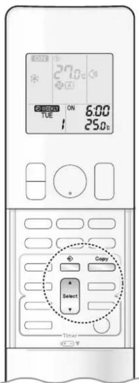
27.0°C ON TUE 6:00 25.0°C Copy Select TimerCopy mode
- A reservation made once can be copied to another day of the week. The whole reservation of the selected day of the week will be copied.

text_image
Programme 1 Programme 2 Programme 3 Programme 4 [Monday] ON OFF ON OFF 25.0°C 27.0°C 6:00 8:30 17:30 22:00 COPY Programme 1 Programme 2 Programme 3 Programme 4 [Tuesday] ON OFF ON OFF 25.0°C 27.0°C 6:00 8:30 17:30 22:00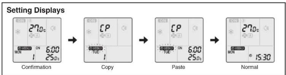
flowchart
graph LR
    A["Setting Displays"] --> B["Confirmation"]
    B --> C["Copy"]
    C --> D["Paste"]
    D --> E["Normal"]
- Press
- Press Select to confirm the day of the week to be copied.
- Press Copy
- The whole reservation of the selected day of the week will be copied.
- Press Select to select the destination day of the week.
-
Press Copy
-
The reservation will be copied to the selected day of the week. The whole reservation of the selected day of the week will be copied.
• To continue copying the settings to other days of the week, repeat STEP 4 and STEP 5. -
Press ☐ to complete the setting.
- “WEEKLY” appears on the LCD and WEEKLY TIMER operation is activated.
NOTE
Note on COPY MODE
- The entire reservation of the source day of the week is copied in the copy mode. In the case of making a reservation change for any day of the week individually after copying the content of weekly reservations, press and change the settings in the steps of Setting mode. ▶Page 23

text_image
27.0°C ON TUE 6:00 25.0°C Weekly Select Next Timer■ Confirming a reservation
• The reservation can be confirmed.

text_image
Setting Displays TUE 15:30 Normal Confirmation ON 6:00 TUE 25.0°C1. Press
- The day of the week and the reservation number of the current day will be displayed.
2. Press to select the day of the week and the reservation number to be confirmed.
- Pressing displays the reservation details.
- To change the confirmed reserved settings, select the reservation number and press. The mode is switched to setting mode. Proceed to Setting mode STEP 4. ▶Page 23
3. Press to exit the confirmation mode.
- “ WEEKLYrs on the LCD and WEEKLY TIMER operation is activated.
• The TIMER lamp lights orange.
Display
■ To deactivate WEEKLY TIMER operation
Press ☐ while “ Ⓧ WEEKLY ” is displayed on the LCD.
• “ MEAN bears from the LCD.
• The TIMER lamp goes off.
• To reactivate the WEEKLY TIMER operation, press ____ again.
- If a reservation deactivated with weekly is activated once again, the last reservation mode will be used.
NOTE
- If not all the reservation settings are reflected, deactivate the WEEKLY TIMER operation once. Then press ____ again to reactivate the WEEKLY TIMER operation.

WEEKLY TIMER Operation

text_image
27.0°C ON TUE 6:00 25.0°C Weekly Select Next Timer■ To delete a reservation
An individual reservation
1. Press
- The day of the week and the reservation number will be displayed.
2. Press to select the day of the week and the reservation number to be deleted.
3. Press Next
• “ WEEKLY ” or “ ONlink. OFF
4. Press until no icon is displayed.
- Pressing changes the ON/OFF TIMER mode in sequence.
- Selecting "blank" will cancel any reservation you may have.
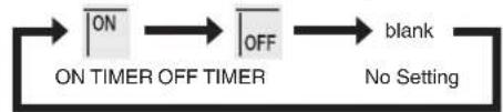
flowchart
graph LR
    A["ON"] --> B["OFF"]
    B --> C["blank"]
    C --> D["No Setting"]
    style A fill:#f9f,stroke:#333
    style B fill:#f9f,stroke:#333
    style C fill:#ccf,stroke:#333
    style D fill:#cfc,stroke:#333
Pressing Select puts the sequence in reverse.
5. Press Next .
- The selected reservation will be deleted.
6. Press .
- If there are still other reservations, WEEKLY TIMER operation will be activated.
Reservations for each day of the week
- This function can be used for deleting reservations for each day of the week.
- It can be used while confirming or setting reservations.
1. Press
- The day of the week and the reservation number will be displayed.
2. Press Select to select the day of the week to be deleted.
3. Hold for about 5 seconds.
- The reservation of the selected day of the week will be deleted.
4. Press .
- If there are still other reservations, WEEKLY TIMER operation will be activated.
All reservations
Hold Weekly for about 5 seconds with the normal display.
- Be sure to direct the remote controller toward the indoor unit and check for a receiving tone.
- This operation cannot be used for the WEEKLY TIMER setting display.
- All reservations will be deleted.
Care and Cleaning

CAUTION
- Before cleaning, be sure to stop the operation and turn off the circuit breaker.
- Do not touch the aluminum fins of the indoor unit. If you touch those parts, this may cause an injury.
■ Quick reference
Cleaning parts
Front panel
- Wipe it with a soft damp cloth.
- Only neutral detergent may be used.
If dirty

natural_image
Cross-sectional diagram of an air conditioner unit showing internal compartments and ventilation slots (no text or labels)

natural_image
Two curved, grid-patterned panels with a small dot on one panel (no text or symbols)Air filter
• Vacuum dust or wash the filter.
Once every 2 weeks
Page 29
Indoor unit and remote controller
- Wipe them with a soft cloth.
If dirty
Deodorizing filter (enzyme blue)
To purchase the filters (Table 1) or to purchase the another type, contact the dealer where you bought the air conditioner.
The method of cleaning and replacement of the filters may differ depending on the model. Refer to the label attached to the separately sold filters themselves.
Table 1
| Item Part No. | |
| Air quality filter (enzyme blue with PM2.5) - without frame (set of 2) | BAFP094A43 |
| Deodorizing filter (enzyme blue) - without frame (set of 2) BAFP094A41 | |
| Dust collection filter (PM 2.5) - without frame (set of 2) BAFP046A41 | |
| Titanium apatite deodorizing filter - without frame (set of 2) KAF970A46 | |
Deodorizing filter (enzyme blue), Titanium apatite deodorizing filter.
• Vacuum dust or replace the filter. [Cleaning] [Replacement]
Once every 6 months Once every 3 years
▶Page 30
▶Page 30
Air quality filter (enzyme blue with PM2.5), Dust collection filter (PM 2.5)
- No cleaning is required. Please replace the filter every 6 months. ▶Page 30
NOTE
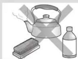
For cleaning, do not use any of the following:
• Water hotter than 40°C
• Volatile liquid such as benzene, petrol and thinner
- Polishing compounds
- Rough materials such as a scrubbing brush
natural_image
Illustration of a kettle, a brush, and a bottle (no text or symbols)Care and Cleaning
Air filter
1. Open the front panel.
- Hold the front panel by the sides and open it.

natural_image
Diagram of a car air conditioner unit showing airflow direction and ventilation slots (no text or symbols)2. Pull out the air filters.
- Push the filter tab at the centre of each air filter a little upwards, then pull it down.

text_image
1) Push 2) Pull down3. Wash the air filters with water or clean them with vacuum cleaner.
- It is recommended to clean the air filters every 2 weeks.
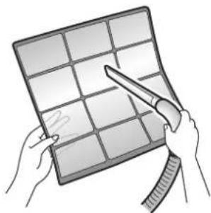
natural_image
Illustration of hands holding a grid-based object with a tool, no text or symbols presentIf the dust does not come off easily
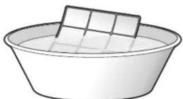
- Wash the air filters with neutral detergent thinned with lukewarm water, then dry them up in the shade.
natural_image
Simple line drawing of a basin with a rectangular dish on top (no text or symbols)4. Reattach the filters.
5. Close the front panel slowly.
- Press the panel at both sides and the centre.
natural_image
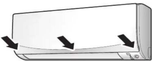
Illustration of a wall-mounted air conditioner unit with three black arrows indicating airflow or cooling direction (no text or symbols)- Make sure that the front panel is securely fixed.
■ Filter (small)
* For the applicable filter type, please refer to ▶Page 28.
Attaching
-
Open the front panel and pull out the air filters. ▶ Page 29
-
Insert the filter.
- Check that the filters are inserted securely under the tabs.
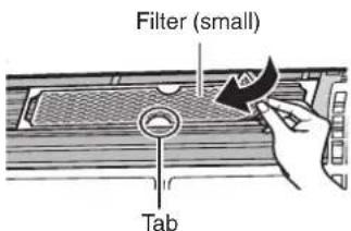
text_image
Filter (small) TabCleaning and Replacement
-
Open the front panel and pull out the air filters. ▶ Page 29
-
Take off the filter.
- Remove the filters from the tabs.
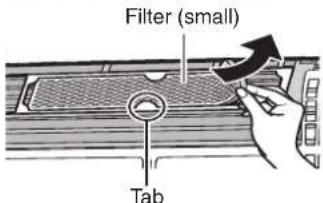
text_image
Filter (small) Tab- Clean or replace.
[Cleaning]
Deodorizing filter (enzyme blue) : Blue / Titanium apatite deodorizing filter : Blue-Black
3-1 Vacuum dust, and soak in lukewarm water or water for about 10 to 15 minutes if very dirty.
3-2 After washing, shake off remaining water and let them dry in the shade.
- This filter can be renewed by washing it with water once every 6 months and we recommend replacing it once every 3 years. - Do not wiring out the filter when removing water from it.
Air quality filter (enzyme blue with PM2.5) : Blue-White / Dust collection filter (PM 2.5) : White
- Do not wash the filters as this will reduce their efficiency. - It is recommended to replace it once every 6 months.
[Replacement]
Remove each filter from the front grille by detaching them from the 6 tabs and then install the new filters.
- When attaching the filter, check that the filter is properly set in the tabs.
- Set the filters as they were and close the front panel.
- Press the front panel at both sides and the center.
NOTE
• Operation with dirty filters:
- cannot deodorise the air,
- cannot clean the air,
– results in poor heating or cooling,
- may cause odour.
- Dispose of old filters as non-flammable waste.
Care and Cleaning
■ Prior to a long period of non-use
- Operate the FAN mode for several hours on a fine day to dry out the inside.
1) Press and select " .
2) Press 0-0F and start the operation.
2. After operation stops, turn off the circuit breaker for the room air conditioner.
3. Clean the air filters and reattach them. ▶Page 29
4. To prevent battery leakage, take out the batteries from the remote controller.
■ We recommend periodical maintenance
- In certain operating conditions, the inside of the air conditioner may get foul after several seasons of use, resulting in poor performance. It is recommended to have periodical maintenance by a specialist in addition to regular cleaning by the user.
- For specialist maintenance, please contact the dealer where you bought the air conditioner.
- The maintenance cost must be borne by the user.
FAQ
Indoor unit
The flap does not start swinging immediately.
- The air conditioner is adjusting the position of the flap. The flap will start moving soon.
The air conditioner stops generating airflow during HEAT operation.
- Once the set temperature is reached, the airflow rate is reduced and operation stopped in order to avoid generating a cool airflow. Operation will resume automatically when the indoor temperature falls.
HEAT operation stops suddenly and a flowing sound is heard.
- The outdoor unit is defrosting. HEAT operation starts after the frost on the outdoor unit has been removed. This can take about 4 to 12 minutes.
Operation does not start soon.
■ When ⏻ was pressed soon after operation was stopped.
■ When the mode was reselected.
• This is to protect the air conditioner. You should wait for about 3 minutes.
Outdoor unit
The outdoor unit emits water or steam.
In HEAT operation
- The frost on the outdoor unit melts into water or steam when the air conditioner is in defrosting operation.
■ In COOL or DRY operation - Moisture in the air condenses into water on the cool surface of the outdoor unit piping and drips.
Different sounds are heard.
■ A sound like flowing water
- This sound is generated because the refrigerant in the air conditioner is flowing.
- This is a pumping sound of the water in the air conditioner and can be heard when the water is pumped out from the air conditioner during COOL or DRY operation.
■ Blowing sound
- This sound is generated when the flow of the refrigerant in the air conditioner is switched over.
■ Ticking sound - This sound is generated when the cabinet and frame of the air conditioner slightly expand or shrink as a result of temperature changes.
■ Whistling sound
- This sound is generated when refrigerant flows during defrosting operation.
■ Clicking sound during operation or idle time - This sound is generated when the refrigerant control valves or the electrical parts operate.
■ Clopping sound
-
This sound is heard from the inside of the air conditioner when the exhaust fan is activated while the room doors are closed. Open the window or turn off the exhaust fan.
■ Rotating machinery causes sound -
Sound is heard when the vertical swing flaps and the horizontal swing flaps move.
- When the air conditioner is operating in a quiet environment and the airflow rate of the indoor unit is set to Quiet Mode or Low Mode, the motion of the swing flaps may cause sound.

natural_image
Illustration of a large air conditioner unit with mesh grille and side-mounted buttons (no text or symbols)Troubleshooting
Before making an inquiry or a request for repair, please check the following.
If the problem persists, consult your dealer.

Not a problem
This case is not a problem.

Check
Please check again before requesting repairs.
The air conditioner does not operate
| Case Description / what to check | |
| OPERATION lamp is off. | Has the circuit breaker been tripped or the fuse blown?Is there a power failure?Are batteries set in the remote controller? |
| OPERATION lamp is blinking. | Turn off the power with the circuit breaker and restart operation with the remote controller.If the OPERATION lamp is still blinking, check the error code and consult your dealer. |
The air conditioner suddenly stops operating
| Case Description / what to check | |
| OPERATION lamp is on. | To protect the system, the air conditioner may stop operating after sudden large voltage fluctuations. It automatically resumes operation in about 3 minutes. |
| OPERATION lamp is blinking. | Is there anything blocking the air inlet or air outlet of the indoor unit or outdoor unit? Stop operation and after turning off the circuit breaker, remove the obstruction. Then restart operation with the remote controller. If the OPERATION lamp is still blinking, check the error code and consult your dealer. ▶Page 36 |
The air conditioner does not stop operating
| Case Description / what to check | |
| The air conditioner continues operating even after operation is stopped. | ☑ Immediately after the air conditioner is stopped• The outdoor unit fan continues rotating for about another 1 minute to protect the system.• While the air conditioner is not in operation• When the outdoor temperature is high, the outdoor unit fan may start rotating to protect the system. |
The room does not cool down/ warm up
| Case Description / what to check | |
| Air does not come out. | ☑ In HEATING operationThe air conditioner is warming up. Wait for about 1 to 4 minutes.During defrosting operation, hot air does not flow out of the indoor unit.When the air conditioner operates immediately after the circuit breaker is turned onThe air conditioner is preparing to operate. Wait for about 3 to 15 minutes. |
| Air does not come out / Air comes out. | ? Is the airflow rate setting appropriate?Is the airflow rate setting low, such as “Indoor unit quiet” or “Airflow rate 1”? Increase the airflow rate setting.Is the set temperature appropriate?Is the adjustment of the airflow direction appropriate? |
| Air comes out. | ? Is there any furniture directly under or beside the indoor unit?Is the air conditioner in ECONO operation or OUTDOOR UNIT QUIET operation? ▶Page 18Are the air filters dirty?Is there anything blocking the air inlet or air outlet of the indoor unit or outdoor unit?Is a window or door open?Is an exhaust fan turning? |
Mist comes out
| Case Description / what to check | |
| Mist comes out of the indoor unit. | This happens when the air in the room is cooled into mist by the cold airflow during COOL or other operation. |
Remote controller
| Case Description / what to check | |
| The unit does not receive signals from the remote controller or has a limited operating range. | The batteries may be exhausted.Replace both batteries with new dry batteries AAA.LR03 (alkaline).For details, refer to “Preparation Before Operation”. ▶Page 9Signal communication may be disabled if an electronic-starter-type fluorescent lamp (such as inverter-type lamps) is in the room. Consult your dealer if that is the case.The remote controller may not function correctly if the transmitter is exposed to direct sunlight. |
| LCD is faint, is not working, or the display is erratic. | The batteries may be exhausted.Replace both batteries with new dry batteries AAA.LR03 (alkaline).For details, refer to “Preparation Before Operation”. ▶Page 9 |
| The LCD is blinking and the remote controller cannot be operated. | Battery power has run out.Replace both batteries at the same time with new size AAA.LR03 (alkaline) batteries.Leaving exhausted batteries in the remote controller can result in injury due to battery leakage, rupturing or heating, or lead to equipment failure.(Even when the LCD is blinking, the OFF button remains functional.) |
| Other electric devices start operating. | If the remote controller activates other electric devices, move them away or consult your dealer. |
Air has an odour
| Case Description / what to check | |
| The air conditioner gives off an odour. | The room odour absorbed in the unit is discharged with the airflow.We recommend you to have the indoor unit cleaned. Please consult your dealer. |
Others
| Case Description / what to check | |
| The air conditioner suddenly starts behaving strangely during operation. | ? The air conditioner may malfunction due to lightning or radio.If the air conditioner malfunctions, turn off the power with the circuit breaker and restart the operation with the remote controller. |
| The ON/OFF TIMER does not operate according to the settings. | ? Check if the ON/OFF TIMER and the WEEKLY TIMER are set to the same time.Change or deactivate the settings in the WEEKLY TIMER. ▶Page 22 |
NOTE
Notes on the operating conditions
- If operation continues under any conditions other than those listed in the table,
- A safety device may activate to stop the operation.
- Dew may form on the indoor unit and drip from it when COOL or DRY operation is selected.
| Mode Operating conditions | |
| COOL / DRY | Outdoor temperature: -10.0~46.0°CIndoor temperature: 18.0~32.0°CIndoor humidity: 80% max. |
| HEAT | Outdoor temperature: -15.0~24.0°CIndoor temperature: 10.0~30.0°C |
Troubleshooting
■ Call your dealer immediately

WARNING
When an abnormality (such as a burning smell) occurs, stop operation and turn off the circuit breaker.
- Continued operation in an abnormal condition may result in problems, electric shock or fire.
- Consult the dealer where you bought the air conditioner.
Do not attempt to repair or modify the air conditioner by yourself.
- Incorrect work may result in electric shock or fire.
- Consult the dealer where you bought the air conditioner.
If one of the following symptoms takes place, call your dealer immediately.
- The power cord is abnormally hot or damaged.
- An abnormal sound is heard during operation.
- The circuit breaker, a fuse, or the earth leakage circuit breaker cuts off the operation frequently.
- A switch or a button often fails to work properly.
• There is a burning smell.
• Water leaks from the indoor unit.
Turn off the circuit breaker and call your dealer.

■ After a power failure
- The air conditioner automatically resumes operation in about 3 minutes. Please wait for a while.
Lightning
- If there is a risk lightning could strike in the neighbourhood, stop operation and turn off the circuit breaker to protect the system.
■ Disposal requirements
- Dismantling of the unit, handling of the refrigerant, oil and other parts, should be done in accordance with the relevant local and national regulations.

text_image
00.8°C GREEN ON 28:88 MON TUE WED ON OFF THU FRI BAT SUN 8 ON 28:88a Cancel Timer■ Fault diagnosis by remote controller
- In case the air conditioner is malfunctioning, you can check the error code via the remote controller before consulting with service personnel and informing them of the malfunction code.
-
When Cancel is held down for about 5 seconds, "00" blinks in the temperature display section.
-
Press Cancel repeatedly until a long beep is produced.
- The code indication changes as shown below, and notifies you with a long beep.
| CODE MEANING | ||
| SYSTEM | 00 NORMAL | |
| UA INDOOR-OUTDOOR UNIT COMBINATION FAULT | ||
| U0 REFRIGERANT SHORTAGE | ||
| U2 DROP VOLTAGE OR MAIN CIRCUIT OVERVOLTAGE | ||
| U4 FAILURE OF TRANSMISSION (BETWEEN INDOOR UNIT AND OUTDOOR UNIT) | ||
| INDOOR UNIT | A1 INDOOR PCB DEFECTIVENESS | |
| A5 HIGH PRESSURE CONTROL OR FREEZE-UP PROTECTOR | ||
| A6 FAN MOTOR FAULT | ||
| C4 FAULTY HEAT EXCHANGER TEMPERATURE SENSOR | ||
| C9 FAULTY SUCTION AIR TEMPERATURE SENSOR | ||
| OUTDOOR UNIT | EA | COOLING-HEATING SWITCHING ERROR |
| E1 CIRCUIT BOARD FAULT | ||
| E5 OL STARTED | ||
| E6 FAULTY COMPRESSOR START UP | ||
| E7 DC FAN MOTOR FAULT | ||
| E8 OVERCURRENT INPUT | ||
| F3 HIGH TEMPERATURE DISCHARGE PIPE CONTROL | ||
| F6 HIGH PRESSURE CONTROL (IN COOLING) | ||
| H0 SENSOR FAULT | ||
| H6 OPERATION HALT DUE TO FAULTY POSITION DETECTION SENSOR | ||
| H8 DC CURRENT SENSOR FAULT | ||
| H9 FAULTY SUCTION AIR TEMPERATURE SENSOR | ||
| J3 | FAULTY DISCHARGE PIPE TEMPERATURE SENSOR | |
| J6 | FAULTY HEAT EXCHANGER TEMPERATURE SENSOR | |
| L3 ELECTRICAL PARTS HEAT FAULT | ||
| L4 HIGH TEMPERATURE AT INVERTER CIRCUIT HEATSINK | ||
| L5 OUTPUT OVERCURRENT | ||
| P4 FAULTY INVERTER CIRCUIT HEATSINK TEMPERATURE SENSOR | ||
NOTE
- A short beep and 2 consecutive beeps indicates non-corresponding codes.
- To cancel the code display, hold down for about 5 seconds. The code display also clears if no button is pressed for 1 minute.
MEMO
Quick Reference
text_image
ON 27.0°C MON 15:30 On/OffFAN Temp Mode Swing 10°C → 30°C 18°C ← 32°C 18°C ← 30°C
flowchart
graph TD
    A["MODE"] --> B["A"]
    B --> C["Recovery to Air"]
    C --> D["Recovery to Air"]
    D --> E["Recovery to Air"]
    E --> F["Recovery to Air"]
    F --> G["Recovery to Air"]
    G --> H["Recovery to Air"]
    H --> I["Recovery to Air"]
    I --> J["Recovery to Air"]
    J --> K["Recovery to Air"]
    K --> L["Recovery to Air"]
    L --> M["Recovery to Air"]
    M --> N["Recovery to Air"]
    N --> O["Recovery to Air"]
    O --> P["Recovery to Air"]
    P --> Q["Recovery to Air"]
    Q --> R["Recovery to Air"]
    R --> S["Recovery to Air"]
    S --> T["Recovery to Air"]
    T --> U["Recovery to Air"]
    U --> V["Recovery to Air"]
    V --> W["Recovery to Air"]
    W --> X["Recovery to Air"]
    X --> Y["Recovery to Air"]
    Y --> Z["Recovery to Air"]
    Z --> AA["Recovery to Air"]
    AA --> AB["Recovery to Air"]
    AB --> AC["Recovery to Air"]
    AC --> AD["Recovery to Air"]
    AD --> AE["Recovery to Air"]
    AE --> AF["Recovery to Air"]
    AF --> AG["Recovery to Air"]
    AG --> AH["Recovery to Air"]
    AH --> AI["Recovery to Air"]
    AI --> AJ["Recovery to Air"]
    AJ --> AK["Recovery to Air"]
    AK --> AL["Recovery to Air"]
    AL --> AM["Recovery to Air"]
    AM --> AN["Recovery to Air"]
    AN --> AO["Recovery to Air"]
    AO --> AP["Recovery to Air"]
    AP --> AQ["Recovery to Air"]
    AQ --> AR["Recovery to Air"]
    AR --> AS["Recovery to Air"]
    AS --> AT["Recovery to Air"]
    AT --> AU["Recovery to Air"]
    AU --> AV["Recovery to Air"]
    AV --> AW["Recovery to Air"]
    AW --> AX["Recovery to Air"]
    AX --> AY["Recovery to Air"]
    AY --> AZ["Recovery to Air"]
    AZ --> BA["Recovery to Air"]
    BA --> BB["Recovery to Air"]
    BB --> BC["Recovery to Air"]
    BC --> BD["Recovery to Air"]
    BD --> BE["Recovery to Air"]
    BE --> BF["Recovery to Air"]
    BF --> BG["Recovery to Air"]
    BG --> BH["Recovery to Air"]
    BH --> BI["Recovery to Air"]
    BI --> BJ["Recovery to Air"]
    BJ --> BK["Recovery to Air"]
    BK --> BL["Recovery to Air"]
    BL --> BM["Recovery to Air"]
    BM --> BN["Recovery to Air"]
    BN --> BO["Recovery to Air"]
    BO --> BP["Recovery to Air"]
    BP --> BQ["Recovery to Air"]
    BQ --> BR["Recovery to Air"]
    BR --> BS["Recovery to Air"]
    BS --> BT["Recovery to Air"]
    BT --> BU["Recovery to Air"]
    BU --> BV["Recovery to Air"]
    BV --> BW["Recovery to Air"]
    BW --> BX["Recovery to Air"]
    BX --> BY["Recovery to Air"]
    BY --> BZ["Recovery to Air"]
DAIKIN INDUSTRIES, LTD.
Head office:
Umeda Center Bldg., 2-4-12, Nakazaki-Nishi,
Kita-ku, Osaka, 530-8323 Japan
Tokyo office:
JR Shinagawa East Bldg., 2-18-1, Konan,
Minato-ku, Tokyo, 108-0075 Japan
https://www.daikin.com

The two-dimensional bar code is a manufacturing code.
OPERATION MANUAL
DAIKIN ROOM AIR CONDITIONER

natural_image
Line drawing of a single air conditioner unit (no text or symbols)MODELS
FTXV50W2VMA
FTXV60W2VMA
FTXV71W2VMA

natural_image
Stylized grayscale globe illustration showing a city skyline above Earth with continents and oceans below (no text or symbols)Features
Enhanced comfort and energy savings
INTELLIGENT EYE
The INTELLIGENT EYE sensor detects human movement in a room. If no one is in the room for more than 20 minutes, the operation automatically changes to energy saving operation.
▶Page 15

WEEKLY TIMER
Up to 4 timer settings can be saved for each day of the week according to your family's life style. The WEEKLY TIMER allows you to set on/off times and the desired temperature. ▶Page 22
Other functions

COMFORT AIRFLOW OUTDOOR UNIT QUIET
The airflow direction is upward while in COOL operation, and downward while in HEAT operation. This function prevents cold or warm air from blowing directly on your body. ▶Page 14
OUTDOOR UNIT QUIET operation assures a low noise level of the outdoor unit. This function is useful to maintain a quiet neighbourhood.
Page 18
natural_image
Modern minimalist living room interior with white sofa, wall-mounted air conditioner, and potted tree (no text or symbols visible)
ECONO
This function enables efficient operation by limiting the maximum power consumption. It is useful when using the air conditioner and other electrical devices simultaneously on a shared electrical circuit. ▶Page 18
Contents
Read Before Operation
Safety Precautions 3
Names of Parts 5
Preparation Before Operation 9
Basic Operation

AUTO · DRY · COOL · HEAT · FAN Operation ....11

Adjusting the Airflow Rate .....12

Adjusting the Airflow Direction .....13
Useful Functions

COMFORT AIRFLOW Operation .....14

INTELLIGENT EYE Operation .....15

POWERFUL Operation ......17

ECONO / OUTDOOR UNIT QUIET Operation ....18
TIMER Operation

ON/OFF TIMER Operation .....19

WEEKLY TIMER Operation ......22
Care
Care and Cleaning 28
When the Need Arises
FAQ 32
Troubleshooting 33
Safety Precautions
| Read the precautions in this manual carefully before operating the unit. | This appliance is filled with R32. |
- Keep this manual where the user can easily find it.
- The precautions described herein are classified as WARNING and CAUTION. They both contain important information regarding safety. Be sure to observe all precautions without fail.
| WARNING | Failure to follow these instructions properly may result in personal injury or loss of life. |
| CAUTION | Failure to observe these instructions properly may result in property damage or personal injury, which may be serious depending on the circumstances. |
| Never attempt. | Be sure to follow the instructions. | Be sure to establish an earth connection. |
- After reading, keep this manual in a convenient place so that you can refer to it whenever necessary. If the equipment is transferred to a new user, be sure also to hand over the manual.

WARNING

- Do not use means to accelerate the defrosting process or to clean, other than those recommended by the manufacturer.
- The appliance must be stored in a room without continuously operating ignition sources (for example: open flames, an operating gas appliance or an operating electric heater).
- Do not pierce or burn.
- Be aware that refrigerants may not contain an odour.
- The appliance must be installed, operated and stored in a room with floor area larger than 4.6m² for 50/60 class, 4.9m² for 71 class. Maintain an installation height of 1.8m or more from the floor surface to the bottom of the appliance. If the size of the room where the appliance is to be installed has less than the indicated minimum floor area, install it in a well ventilated room. For details refer to the WARNING list in the “Safety Precautions” section of the installation manual for the outdoor unit.
• To avoid fire, explosion or injury, do not operate the unit when harmful gases (e.g. flammable or corrosive) are detected near the unit. - Be aware that prolonged, direct exposure to cool or warm air from the air conditioner, or to air that is too cool or too warm, can be harmful to your physical condition and health.
- Do not place objects, including rods, your fingers, etc., in the air inlet or outlet. Product damage or personal injury may result due to contact with the air conditioner's high-speed fan blades.
- Do not attempt to repair, dismantle, reinstall or modify the air conditioner yourself as this may result in water leakage, electric shock or fire hazards.
- Do not use flammable spray near the air conditioner, or otherwise fire may result.
- Do not use a refrigerant other than the one indicated on the outdoor unit (R32) when installing, moving or repairing. Using other refrigerants may cause trouble or damage to the unit, and personal injury.
- To avoid electric shock, do not operate with wet hands.

- Beware of fire in case of refrigerant leakage. If the air conditioner is not operating correctly, i.e. not generating cool or warm air, refrigerant leakage could be the cause. Consult your dealer for assistance. The refrigerant within the air conditioner is safe and normally does not leak.
However, in the event of a leakage, contact with a naked burner, heater or cooker may result in generation of noxious gas. Do not use the air conditioner until a qualified service person confirms that the leakage has been repaired.
- Do not attempt to install or repair the air conditioner yourself. Improper workmanship may result in water leakage, electric shock or fire hazards. Please contact your local dealer or qualified personnel for installation and maintenance work.
- If the air conditioner is malfunctioning (giving off a burning odour, etc.), turn off power to the unit and contact your local dealer. Continued operation under such circumstances may result in a failure, electric shock or fire hazards.
- Be sure to install an earth leakage circuit breaker. Failure to install an earth leakage circuit breaker may result in electric shock or fire.

- Be sure to earth the unit. Do not earth the unit to a utility pipe, lightning conductor or telephone earth lead. Imperfect earthing may result in electric shock.

CAUTION

- Do not use the air conditioner for purposes other than those for which it is intended. Do not use the air conditioner for cooling precision instruments, food, plants, animals or works of art as this may adversely affect the performance, quality and/or longevity of the object concerned.
- Do not expose plants or animals directly to the airflow from the unit as this may cause adverse effects.
- Do not place appliances that produce naked flames in places exposed to the airflow from the unit as this may impair combustion of the burner.
- Do not block the air inlets nor outlets. Impaired airflow may result in insufficient performance or trouble.

- Do not sit on the outdoor unit, put things on the unit, or pull the unit. Doing so may cause accidents, such as falling or toppling down, thus resulting in injury, product malfunctioning, or product damage.
- Do not place objects that are susceptible to moisture directly beneath the indoor or outdoor units. Under certain conditions, condensation on the main unit or refrigerant pipes, air filter dirt or drain blockage may cause dripping, resulting in fouling or failure of the object concerned.
- After prolonged use, check the unit stand and its mounts for damage. If they are left in a damaged condition, the unit may fall and cause injury.
- To avoid injury, do not touch the air inlet or aluminium fins of the indoor or outdoor units.
- The appliance is not intended for use by unattended young children or infirm persons. Impairment of bodily functions and harm to health may result.
- Children should be supervised to ensure that they do not play with the unit or its remote controller. Accidental operation by a child may result in impairment of bodily functions and harm health.
- Avoid impacts to the indoor and outdoor units, or otherwise product damage may result.
- Do not place flammable items, such as spray cans, within 1m of the air outlet.
The spray cans may explode as a result of hot air from the indoor or outdoor units.
- Be careful not to let pets urinate on the air conditioner. Urination on the air conditioner may result in electric shock or fire.
- Do not wash the air conditioner with water, as this may result in electric shock or fire.
- Do not place water containers (vases, etc.) above the unit, as this may result in electric shock or fire hazards if they should topple over.
- Do not insert the batteries in the wrong polarity (+/-) orientation as this may result in short circuiting, fire, or battery leakage.
- Do not sit or hang on the panel. The panel may fall, and injury or product malfunctioning may result.
- Do not sway the panel. The panel may hit people or objects, and injury or property damage may result.
- Do not let children play around the panel. Injury or property damage may result.
- Do not pull the wires. The wires may be broken and the panel may fall, and injury or property damage may result.
- Do not locate obstacles in the route. The panel may fall, and injury or property damage may result.
- Do not bend or damage the wires. The wires may be broken and the panel may fall, and injury or property damage may result.
- Do not put objects on the panel, or otherwise production malfunctioning may result.
- Do not use an unstable stand at the time of operating or maintaining the air conditioner, or otherwise you may topple over or injury yourself.
- Locate the remote controller in places out of reach of children. The wrong operation of the remote controller may result in injury.

- To avoid oxygen depletion, ensure that the room is adequately ventilated if equipment such as a burner is used together with the air conditioner.
- Before cleaning, be sure to stop unit operation and turn off the circuit breaker. Otherwise, an electric shock and injury may result.
- Only connect the air conditioner to the specified power supply circuit. Power supplies other than the one specified may result in electric shock, overheating and fires.
- Arrange the drain hose to ensure smooth drainage. Imperfect drainage may cause wetting of the building, furniture, etc.
- Do not place objects in direct proximity of the outdoor unit and do not let leaves and other debris accumulate around the unit. Leaves are a hotbed for small animals which can enter the unit. Once inside the unit, such animals can cause malfunctions, smoke or fire if they come into contact with electrical parts.
- Do not place objects around the indoor unit.
Doing so may have an adverse influence on the performance, product quality, and life of the air conditioner. - This appliance is not intended to be used by persons with reduced physical, sensory or mental capabilities, or with lack of operation knowledge, unless they have been given supervision or instruction concerning the appliance use by person responsible for their safety. Keep out of children's reach to ensure that they do not play with the appliance.
Precautions relating to area surrounding the indoor and outdoor units
■ Be sure to follow the instructions below.
- The indoor unit is at least 1m away from any television or radio set (unit may cause interference with the picture or sound).
- Refrain from using the units in areas prone to high levels of oily smoke, such as a kitchen. Water leakage may result.
Names of Parts
Indoor Unit
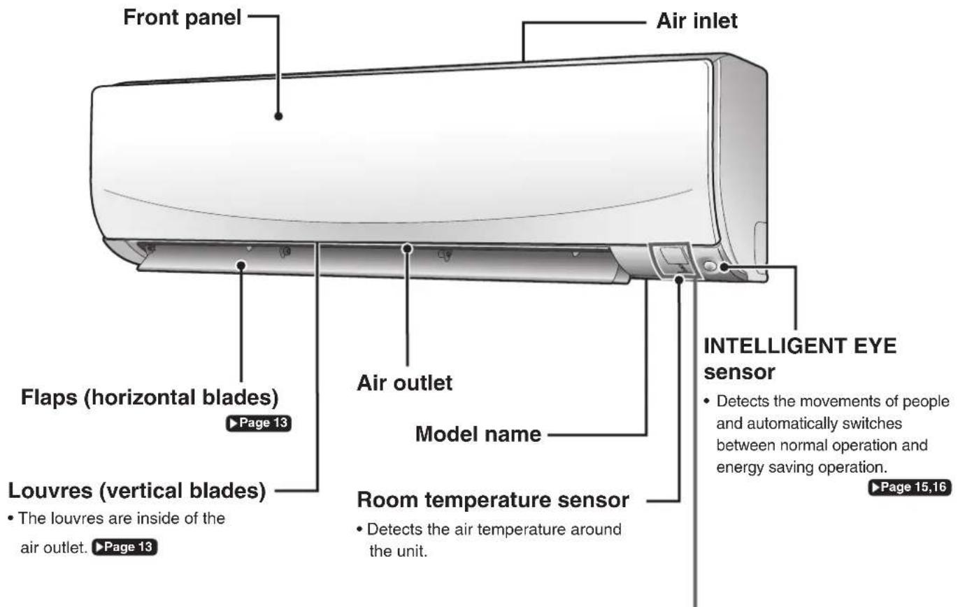
text_image
Front panel Air inlet Flaps (horizontal blades) Page 13 Air outlet Model name InTELLIGENT EYE sensor • Detects the movements of people and automatically switches between normal operation and energy saving operation. • The louvres are inside of the air outlet. Page 13 Room temperature sensor • Detects the air temperature around the unit. Page 15,16Display
Signal receiver
- Receives signals from the remote controller.
- When the unit receives a signal, you will hear a beep sound.
| Case Sound type |
| Operation start beep-beep |
| Setting changed beep |
| Operation stop long beep |
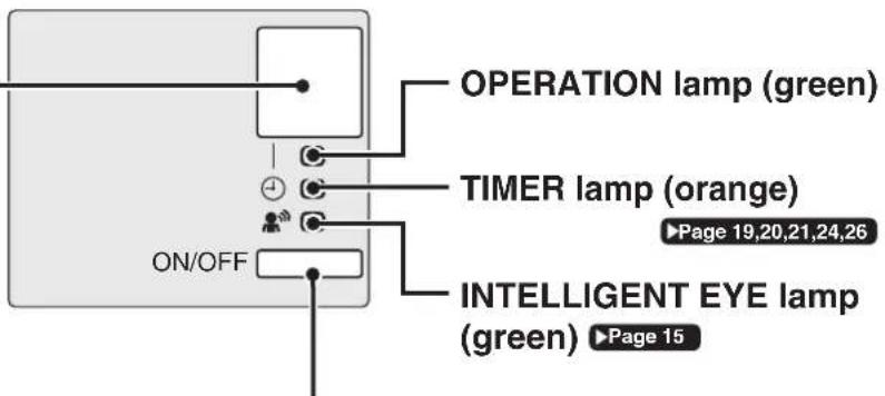
text_image
OPERATION lamp (green) TIMER lamp (orange) ON/OFF Page 19,20,21,24,26 INTELLIGENT EYE lamp (green) Page 15Indoor unit ON/OFF switch
- Press this switch once to start operation. Press once again to stop it.
- For the operation mode setting, refer to the following table.
| Mode Temperature setting Airflow rate | |
| AUTO 25.0°C AUTO | |
- This switch can be used when the remote controller is missing or out of batteries.
■ Open the front panel
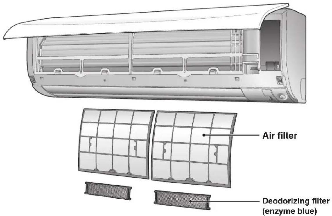
text_image
Air filter Deodorizing filter (enzyme blue)Outdoor Unit
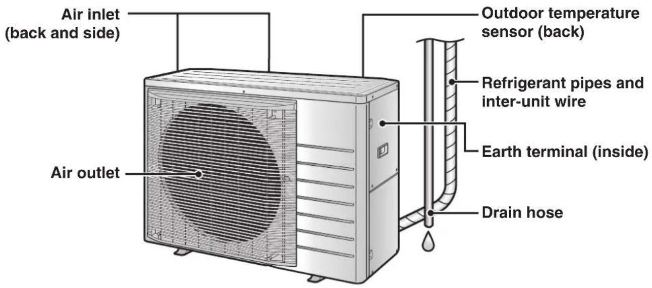
text_image
Air inlet (back and side) Outdoor temperature sensor (back) Refrigerant pipes and inter-unit wire Earth terminal (inside) Drain hose Air outletRemote Controller
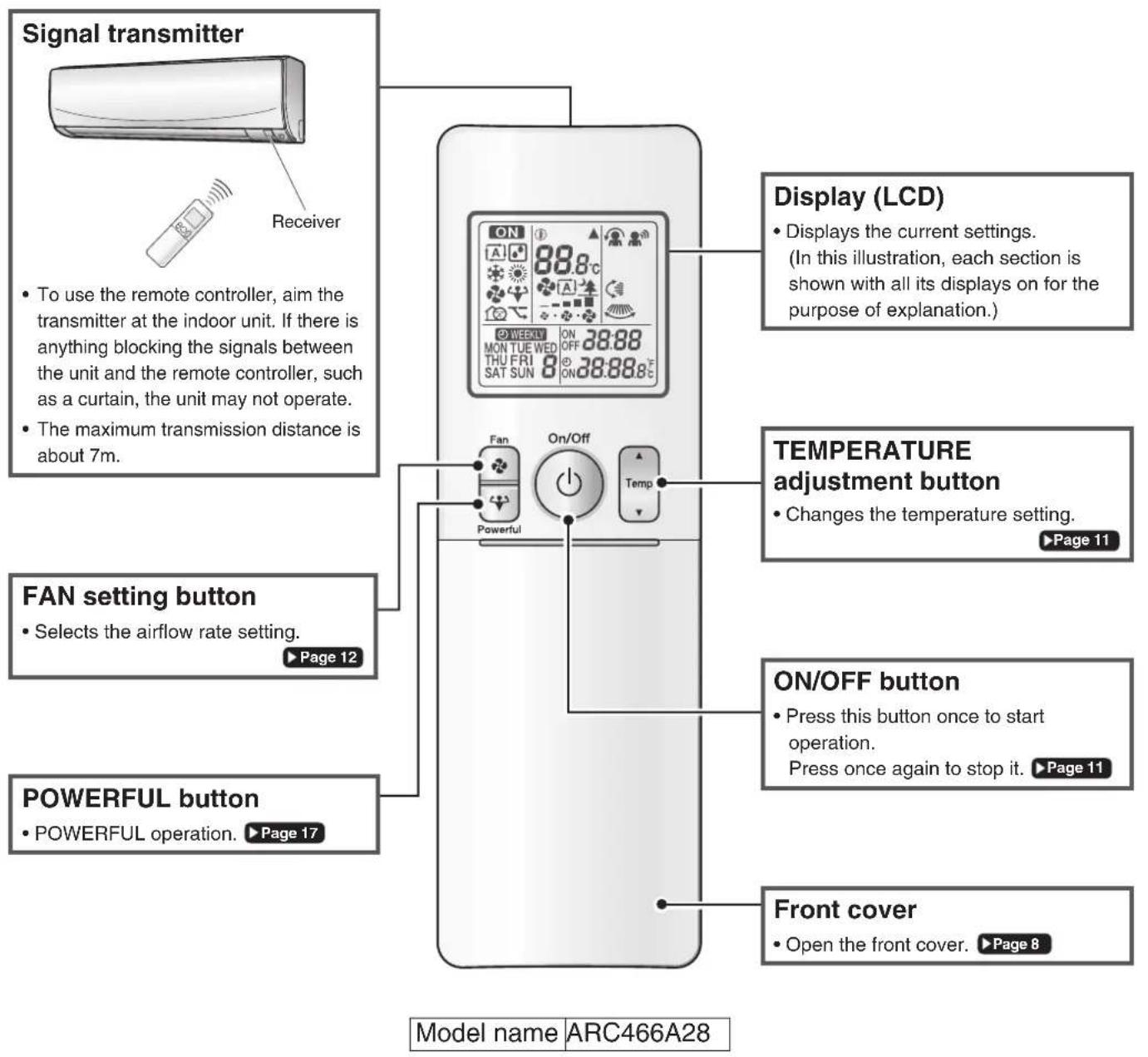
text_image
Signal transmitter Receiver To use the remote controller, aim the transmitter at the indoor unit. If there is anything blocking the signals between the unit and the remote controller, such as a curtain, the unit may not operate. The maximum transmission distance is about 7m. Display (LCD) Displays the current settings. (In this illustration, each section is shown with all its displays on for the purpose of explanation.) TEMPERATURE adjustment button Changes the temperature setting. ▶Page 11 FAN setting button Selects the airflow rate setting. ▶Page 12 POWERFUL button POWERFUL operation. ▶Page 17 ON/OFF button Press this button once to start operation. Press once again to stop it. ▶Page 11 Front cover Open the front cover. ▶Page 8 Model name ARC466A28Names of Parts
■ Open the front cover
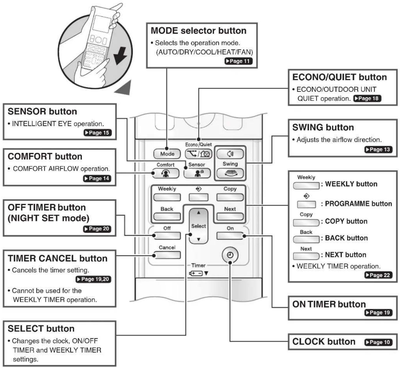
text_image
MODE selector button • Selects the operation mode. (AUTO/DRY/COOL/HEAT/FAN) ▶ Page 11 ECONO/QUIET button • ECONO/OUTDOOR UNIT QUIET operation. ▶ Page 18 SENSOR button • INTELLIGENT EYE operation. ▶ Page 15 COMFORT button • COMFORT AIRFLOW operation. ▶ Page 14 OFF TIMER button (NIGHT SET mode) ▶ Page 20 TIMER CANCEL button • Cancels the timer setting. ▶ Page 19,20 • Cannot be used for the WEEKLY TIMER operation. SELECT button • Changes the clock, ON/OFF TIMER and WEEKLY TIMER settings.Preparation Before Operation

CAUTION
Incorrect handling of batteries can result in injury from battery leakage, rupturing or heating, or lead to equipment failure.
Please observe the following precautions and use safely.
- If the alkaline solution from the batteries should get in the eyes, do not rub the eyes. Instead, immediately flush the eyes with tap water and seek the attention of a medical professional.
- Keep batteries out of reach of children. In the event that batteries are swallowed, seek the immediate attention of a medical professional.
- Do not expose batteries to heat or fire. Do not disassemble or modify batteries. The insulation or gas release vent inside the battery may be damaged, resulting in battery leakage, rupturing, or heating.
- Do not damage or peel off labels on the batteries.
■ To insert the batteries
- Slide the front cover to take it off.
- Insert 2 dry batteries AAA.LR03 (alkaline).
- Replace the front cover.
■ To fix the remote controller holder to a wall
- Choose a place from where the signals reach the unit.
- Fix the holder to a wall, a pillar, or similar location with the screws supplied with the holder.
- Place the remote controller in the remote controller holder.
■ To attach the deodorizing filter (enzyme blue)
- If attaching the separately sold filters, attach them before turning the power on.
■ Turn on the circuit breaker
• After the power is turned on, the flaps of the indoor unit open and close once to set the reference position.
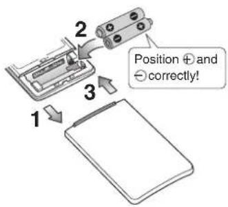
text_image
Position + and - correctly!
text_image
Remote controller Screws Remote controller holderNOTE
Notes on batteries
- To avoid possible injury or damage from battery leakage or rupturing, remove the batteries when not using the product for long periods of time.
- The standard replacement time is 1 year. Both batteries should be replaced at the same time. Be sure to replace them with new size AAA. LR03 (alkaline) batteries.
- When battery power has run out, the LCD will begin blinking as an alert that the batteries need replacing. In some cases, when battery consumption is accelerated owing usage conditions, signal reception may decline before the LCD begins blinking.
- The batteries supplied with the remote controller are for initial operation. The batteries may run out in less than 1 year.
Note on remote controller
- Do not drop the remote controller. Do not get it wet.

text_image
MON 15:30 27.0°C Select Timer■ To set the clock
1. Press

"0.00 appears on the LCD.
"MON" and "💡 blink.
2. Press to set the current day of the week.
3. Press

“ blinks.
4. Press Select to set the clock to the present time.
- Holding down ▲r rapidly increases or decreases the displayed time.
5. Press ⓤ
- Point the remote controller at the indoor unit when pressing the buttons.

“*”blinks.
NOTE
Note on setting the clock
- If the indoor unit's internal clock is not set to the correct time, the ON/OFF TIMER and WEEKLY TIMER will not operate punctually.
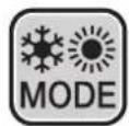
text_image
ON 27.0°C * A MON 15:30 On/Off Temp Mode TimerThe air conditioner operates with the operation mode of your choice.
From the next time on, the air conditioner will operate with the same operation mode.
■ To start
1. Press and select an operation mode.
• Each pressing of the button changes the mode setting in sequence.
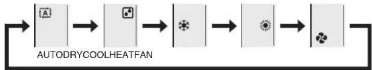
flowchart
graph LR
    A["Start"] --> B["Input"]
    B --> C["Process Step 1"]
    C --> D["Process Step 2"]
    D --> E["End"]
2. Press On/Off
• " ONpears on the LCD.
• The OPERATION lamp lights green.
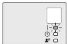
Display
■ To stop
Press again.
• “ ON appears from the LCD.
• The OPERATION lamp goes off.
■ To change the temperature setting
Press Temp
- Press ▲ to raise the temperature and press ▼ to lower the temperature.
Each pressing of the button changes the temperature by 0.5^ C.
| COOL operation | HEAT operation | AUTO operation | DRY or FAN operation |
| 18.0 - 32.0°C | 10.0 - 30.0°C | 18.0 - 30.0°C | The temperature setting cannot be changed. |
NOTE
Notes on AUTO operation
- In AUTO operation, the system selects an appropriate operation mode (COOL or HEAT) based on the indoor temperature, then starts the operation.
- The system automatically reselects setting at a regular interval to bring the indoor temperature to user-setting level.
Note on COOL operation
- This air conditioner cools the room by releasing the heat in the room outside.
Therefore, the cooling performance of the air conditioner may be degraded if the outdoor temperature is high.
Note on DRY operation
- Eliminates humidity while maintaining the indoor temperature as much as possible. It automatically controls temperature and airflow rate, so manual adjustment of these functions is unavailable.
Notes on HEAT operation
- Since this air conditioner heats the room by taking heat from outdoor air to indoors, the heating capacity becomes smaller in lower outdoor temperatures. If the heating effect is insufficient, it is recommended to use another heating appliance in combination with the air conditioner.
- The heat pump system heats the room by circulating hot air around all parts of the room. After the start of HEAT operation, it takes some time before the room gets warmer.
- In HEAT operation, frost may occur on the outdoor unit and lower the heating capacity. In that case, the system switches into defrosting operation to take away the frost.
Note on FAN operation
• This mode is valid for fan only.

Adjusting the Airflow Rate

text_image
27.0°C MON 15:30 FanYou can adjust the airflow rate to increase your comfort.
■ To adjust the airflow rate setting

• Each pressing of the button changes the airflow rate setting in sequence.
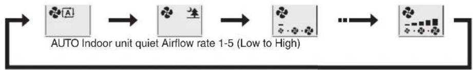
flowchart
graph LR
    A["AUTO Indoor unit quiet Airflow rate 1-5 (Low to High)"] --> B["..."]
    B --> C["..."]
    C --> D["..."]
    D --> E["..."]
    E --> F["..."]
- When the airflow is set to “quiet operation starts and noise from the indoor unit will become quieter.
- In the quiet operation mode, the airflow rate is set to a weak level.
- In DRY operation, the airflow rate setting cannot be changed.
- At smaller airflow rates, the cooling (heating) effect is also smaller.
Tips for saving energy
Keeping the temperature setting at a moderate level helps save energy.
- Recommended temperature setting for cooling: 26.0 - 28.0°C, heating: 20.0 - 24.0°C
Cover windows with a blind or a curtain.
- Blocking sunlight and air from outdoors increases the cooling (heating) effect.
Keep the air filters clean.
- Clogged air filters cause inefficient operation and waste energy. Clean them once in about every 2 weeks. ▶ Page 29
If you are not going to use the air conditioner for a long period, for example in spring or autumn, turn off the circuit breaker.
- The air conditioner always consumes a small amount of electricity even while it is not operating.
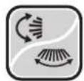
Adjusting the Airflow Direction
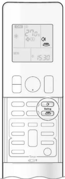
text_image
27.0 MON 15:30 Swing TimerYou can adjust the airflow direction to increase your comfort.
ATTENTION
• Always use a remote controller to adjust the angles of the flaps and louvres.
- If you attempt to move the flaps and louvres forcibly by hand when they are swinging, the mechanism may be damaged.
- Inside the air outlet, a fan is rotating at a high speed.
■ To start auto swing
Up and down airflow direction
Press
• “ Appears on the LCD.
- The flaps (horizontal blades) will begin to swing.
Right and left airflow direction
Press
• “ appears on the LCD.
- The louvres (vertical blades) will begin to swing.
The 3-D airflow direction
Press and .
• “ and ” appear on the LCD.
• The flaps and louvres move in turn.
- To cancel 3-D airflow, press either 📁 or again.
The flaps or louvres will stop moving.

natural_image
Diagram showing a circular icon with rotation arrow and a rectangular device emitting a curved arrow (no text or symbols)
natural_image
Diagram showing airflow around a curved arrow, with no text or symbols present.
natural_image
Diagram showing curved arrows and a magnified inset of a device with a sensor icon (no text or symbols)■ To set the flaps or louvres at the desired position
- This function is effective while the flaps or louvres are in auto swing mode.
Press and when the flaps or louvres reach the desired position.
- In the 3-D airflow, the flaps and louvres move in turn.
- “ 📋” or “ 📌 disappears from the LCD.
NOTE
Note on airflow direction setting
- The movable range of the flaps varies according to the operation mode.
Note on 3-D airflow
- Using 3-D airflow circulates cold air, which tends to collect at the bottom of the room, and hot air, which tends to collect near the ceiling, throughout the room, preventing areas of cold and hot developing.
Movable range of the flaps

text_image
of the flaps COOL / DRY FAN HEAT
COMFORT AIRFLOW Operation
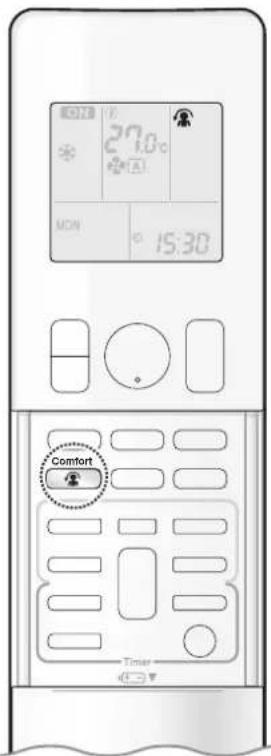
text_image
27.0°C MON 15:30 Comfort TimerThe flow of air will be in the upward direction while in COOL operation and in the downward direction while in HEAT operation, which will provide a comfortable wind that will not come in direct contact with people.

natural_image
Diagram of a wall-mounted air conditioner unit with airflow direction indicated (no text or symbols)COOL operation

natural_image
Pure diagram of a curved pipe or duct with a rectangular component, no text or symbols presentHEAT operation
■ To start

Press
Comfort


appears on the LCD.
| COOL and DRY operation HEAT operation FAN operation | |||
| Flaps direction | Goes up Goes down | Not available | |
| Airflow rate AUTO | |||
■ To cancel

Press
Comfort

again.
• “ disappears from the LCD.
- The flaps will return to the position in memory form before COMFORT AIRFLOW operation.
NOTE
Notes on COMFORT AIRFLOW Operation
- The flaps position will change, preventing air from blowing directly on the occupants of the room.
- POWERFUL operation and COMFORT AIRFLOW operation cannot be used at the same time.
• The airflow rate will be set to AUTO. - If the upward and downward airflow direction is selected, the COMFORT AIRFLOW function will be canceled.
Priority is given to the function of whichever button is pressed last.
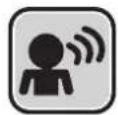
INTELLIGENT EYE Operation

text_image
27.0°C MON 15:30 Sensor TimerThe INTELLIGENT EYE operation detects human movement. If no one is detected in the room for more than 20 minutes, the unit automatically enters energy saving operation.

CAUTION
- Do not place large objects near the INTELLIGENT EYE sensor. Also keep heating units and humidifiers outside the sensor's detection area. This sensor can detect undesirable objects.
- Do not hit or violently push the INTELLIGENT EYE sensor. This can lead to damage and malfunction.

To start

Press Sensor and select the desired model.
• Each time the button is pressed, a different setting option is displayed on the LCD.
• The INTELLIGENT EYE lamp lights green.

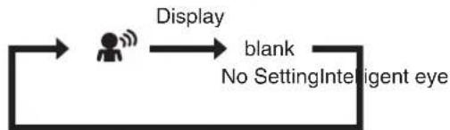
flowchart
graph LR
    A["User Icon"] -->|Display| B["blank"]
    B --> C["No Setting Intelligent eye"]
• The lamp lights when human movement is detected.

To cancel

Press

button.
• The INTELLIGENT EYE lamp goes off.
INTELLIGENT EYE operation is useful for energy saving
■ People are detected in the sensing area.

natural_image
Illustration of an elderly person sitting on a couch with a TV displaying a downward arrow (no text or symbols)The air conditioner is in normal operation while the sensor is detecting human movement.
■ No people are detected in the sensing area.
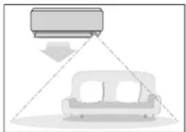
natural_image
Diagram showing a car with a downward arrow and a sofa, no text or symbols presentThe air conditioner will switch to energy-saving mode after 20 minutes.
Energy saving operation
- If no presence detected in the room for 20 minutes, the energy saving operation will start, and the INTELLIGENT EYE lamp goes off. If human movement is detected again, the INTELLIGENT EYE lamp lights up and energy saving operation terminates.
- This operation changes the temperature by -2^ in HEAT / +2^ in COOL / +2^ in DRY operation from the set temperature.
When the room temperature exceeds 30^ C, the operation changes the temperature by +1^ C in COOL / +1^ C in DRY operation from the set temperature. - This operation decreases the airflow rate slightly in FAN operation only.
NOTE
Notes on INTELLIGENT EYE operation
- Application range is as follows.
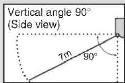
text_image
Vertical angle 90° (Side view) 7m 90°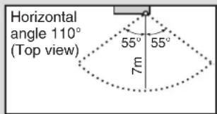
text_image
Horizontal angle 110° (Top view) 55° 55° 7m- The sensor may not detect moving objects further than 7m away. (Please see the application range)
- Sensor detection sensitivity changes according to the indoor unit location, the speed of passers-by, temperature range, etc.
- The sensor could also mistakenly detect pets, sunlight, fluttering curtains and light reflected off of mirrors as passers-by.
- NIGHT SET mode ▶Page 20 will not switch on during use of INTELLIGENT EYE operation.
Note on combination of COMFORT AIRFLOW operation and INTELLIGENT EYE operation
- The airflow rate will be set to AUTO. If the up and down airflow direction is selected, COMFORT AIRFLOW operation will be cancelled. Priority is given to the function of whichever button is pressed last.

POWERFUL Operation

text_image
MON 15:30 PowerfulPOWERFUL operation quickly maximises the cooling (heating) effect in any operation mode. In this mode, the air conditioner operates at maximum capacity.
■ To start
Press during operation.
• “ appears on the LCD.
- POWERFUL operation ends in 20 minutes. Then the system automatically operates again with the previous settings which were used before POWERFUL operation.
■ To cancel
Press again.
• “ disappears from the LCD.
NOTE
Notes on POWERFUL operation
- Pressing causes the settings to be cancelled, and " " disappears from the LCD.
- POWERFUL operation will not increase the capacity of the air conditioner if the air conditioner is already in operation with its maximum capacity demonstrated.
- In COOL, HEAT and AUTO operation
To maximise the cooling (heating) effect, the capacity of outdoor unit increases and the airflow rate becomes fixed at the maximum setting. The temperature and airflow settings cannot be changed. - In DRY operation
The temperature setting is lowered by 2.5°C and the airflow rate is slightly increased. - In FAN operation
The airflow rate is fixed at the maximum setting.
Regarding the combination of POWERFUL and other operations
| POWERFUL + COMFORT AIRFLOW | Not available* |
| POWERFUL + ECONO | |
| POWERFUL + OUTDOOR UNIT QUIET |
*Priority is given to the function of whichever button is pressed last.
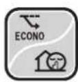
ECONO / OUTDOOR UNIT QUIET Operation

text_image
27.0 MON 15:30 Erona Quiet TieterECONO operation enables efficient operation by limiting the maximum power consumption. This function is useful to prevent the circuit breaker from tripping when the unit operates alongside other appliances on the same circuit.
OUTDOOR UNIT QUIET operation lowers the noise level of the outdoor unit by changing the frequency and fan speed of the outdoor unit. This function is convenient during the night-time operation.
■ To start
Press Econo/Quiet and select the desired mode.
• Each time the button is pressed, a different setting option appears on the LCD.

flowchart
graph LR
    A["ECONO OUTDOOR UNIT QUIET"] --> B["Combination"]
    B --> C["blank\nNo Setting"]
■ To cancel
Press Econo/Quiet until no icon is displayed.
NOTE
Notes on ECONO operation
- This operation is performed with lower power and therefore may not provide a sufficient cooling (heating) effect.
- Pressing ⏻ causes the settings to be cancelled, and “” disappears from the LCD.
- If the power consumption level is already low, switching to ECONO operation will not reduce the power consumption.
Notes on OUTDOOR UNIT QUIET operation
- Even if the operation is stopped by using the remote controller or the indoor unit ON/OFF switch when using OUTDOOR UNIT QUIET operation, "💡" will remain displayed on the remote controller.
- OUTDOOR UNIT QUIET operation will not reduce the frequency nor fan speed if they already are operating at reduced levels.
- This operation is performed with lower power and therefore may not provide a sufficient cooling (heating) effect.
Possible combinations of ECONO / OUTDOOR UNIT QUIET operation and basic operations
| Operation mode | ||||
| DRY COOL HEAT FAN | ||||
| ECONO | √ | √ | √ | - |
| OUTDOOR UNIT QUIET | - | √ | √ | - |

ON/OFF TIMER Operation
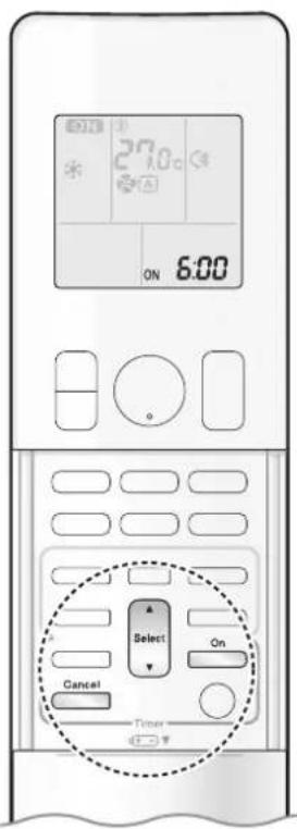
text_image
27.0 ON 6:00 Select Cancel On TimerTimer functions are useful for automatically switching the air conditioner on or off at night or in the morning. You can also use the ON TIMER and OFF TIMER together.
[ON TIMER with a 24 hour clock display] (24 HOUR ON/OFF TIMER)
■ To set
- Check that the clock is correct. If not, set the clock to the present time. ▶Page 10
1. Press On

“5.00pears on the LCD. “ON” blinks.
- “④” and day of the week disappear from the LCD.
2. Press until the time setting reaches the point you like.
• Each pressing of either button increases or decreases the time setting by 10 minutes. Holding down either button changes the setting rapidly.
3. Press on again.
- "ON" and setting time appear on the LCD. - The TIMER lamp lights orange.
Display
■ To cancel
Press Cancel.
- “ON” and setting time disappear from the LCD.
- “ ⏻ ” and day of the week appear on the LCD.
• The TIMER lamp goes off.
NOTE
Note on TIMER operation
- When TIMER is set, the present time is not displayed.
• After the circuit breaker has turned off.
• After a power failure.
• After replacing the batteries in the remote controller.
In the following cases, set the timer again.
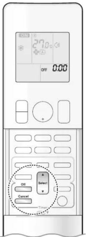
text_image
27.0 OFF 0:00 Select Off Cancel Timer[OFF TIMER with a 24 hour clock display] (24 HOUR ON/OFF TIMER)
■ To set
- Check that the clock is correct. If not, set the clock to the present time. ▶Page 10
1. Press Off
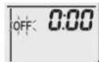
"0:appears on the LCD. "OFF" blinks.
- “ ⊕” and day of the week disappear from the LCD.
2. Press until the time setting reaches the point you like.
• Each pressing of either button increases or decreases the time setting by 10 minutes. Holding down either button changes the time setting rapidly.
3. Press again.
- "OF and setting time appear on the LCD. - The TIMER lamp lights orange.
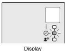
text_image
Display■ To cancel
Press Cancel.
- “OF and setting time disappear from the LCD.
- “ ⏻” and day of the week appear on the LCD.
• The TIMER lamp goes off.
[ON/OFF TIMER combination]
■ To combine
- A sample setting for combining the 2 timers is shown below.

text_image
(Example) Present time: 23:00 (The unit is operating) OFF TIMER at 0:00 ON TIMER at 14:00) Combined OFF 0:00 ON 14:00NOTE
NIGHT SET mode
- When the OFF TIMER is set, the air conditioner automatically adjusts the temperature setting (0.5°C up in COOL, 2.0°C down in HEAT) to prevent excessive cooling (heating) during sleeping hours.

ON/OFF TIMER Operation

text_image
27.0°C ON Ihr Off Select On Cancel Timer[ON/OFF TIMER with an hours remaining display] (COUNT UP-DOWN ON/OFF TIMER)
- Check that the clock is correct. If not, set the clock to the present time. ▶Page 10
1. Press and hold on or for about 5 seconds, when signal indicator (▲) blink, release your finger from the button.

For ON TIMER
"Ibr" appears on the LCD.
"ON" blinks.
For OFF TIMER
"Ihr" appears on the LCD
"OFF" blinks.
- “ ⏻ ” and day of the week disappear from the LCD.
2. Press until the time setting reaches the point you like.
• Each pressing of the button increases or decreases the time setting by 1 hour.
• The time can be set between 1 and 12 hours.
3. Press on or again.
- “ONand” “OFF and setting time appear on the LCD.
• The TIMER lamp lights orange. - To change the display mode from COUNT UP-DOWN ON/OFF TIMER to 24 HOUR ON/OFF TIMER, repeat STEP 1, and continue from STEP 2 of "24 HOUR ON/OFF TIMER".
▶ Page 19, 20
- Timer display mode cannot be changed while "ON" or "OFF" are blinking. Press On or to stop the blinking.
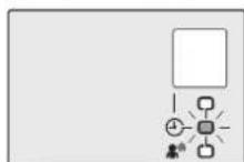
Display
■ Combining display modes
- Different display modes (24 HOUR ON/OFF TIMER and COUNT UP-DOWN ON/OFF TIMER) can be used for the ON TIMER and OFF TIMER simultaneously.
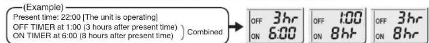
text_image
(Example) Present time: 22:00 [The unit is operating] OFF TIMER at 1:00 (3 hours after present time) ) Combined ON TIMER at 6:00 (8 hours after present time)NOTE
Note on COUNT UP-DOWN ON/OFF TIMER
- After setting, the time displayed on the LCD will automatically count down by 1 hour for every 1 hour that passes. For example, if the OFF TIMER is set to 3 hours, the display will change as follows: 3hr 2hr 1hr blank (OFF)
Switching between ON/OFF TIMER display modes (24 hour clock and hours remaining display)
- When changing timer display modes (from 24 HOUR ON/OFF TIMER to COUNT UP-DOWN ON/OFF TIMER or vice versa), the timer cancels. The timer must be set again to activate it.
WEEKLY TIMER Operation
Up to 4 timer settings can be saved for each day of the week. This is convenient to adapt the WEEKLY TIMER to your family's life style.
■ Setting example of the WEEKLY TIMER
The same timer settings are used from Monday through Friday, while different timer settings are used for the weekend.
| [Monday] | Make timer settings for programmes 1-4. ▶Page 23 | |||
| Programme 1 | Programme 2 | Programme 3 | Programme 4 | |
— 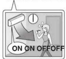 | 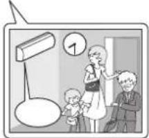 | 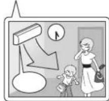 | 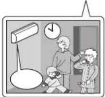 | |
| [Tuesday] to [Friday] | Use the copy mode to make settings for Tuesday to Friday, because these settings are the same as those for Monday. ▶Page 25Pr 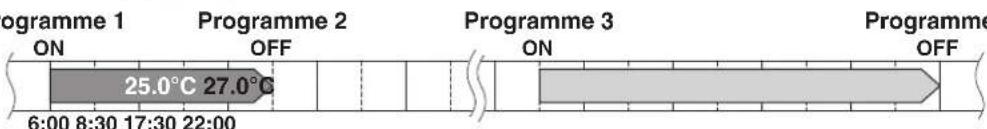 | 4 | ||
| [Saturday] | No timer settings | |||
| [Sunday] | Make timer settings for programmes 1-4. ▶Page 23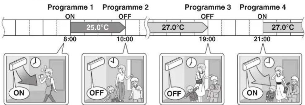 | |||
- Up to 4 reservations per day and 28 reservations per week can be set using the WEEKLY TIMER. The effective use of the copy mode simplifies timer programming.
- The use of ON-ON-ON-ON settings, for example, makes it possible to schedule operating mode and set temperature changes. Furthermore, by using OFF-OFF-OFF-OFF settings, only the turn off time of each day can be set. This will turn off the air conditioner automatically if you forget to turn it off.

WEEKLY TIMER Operation

text_image
27.0°C ON 6:00 25.0°C MON Select Next Timer■ To use WEEKLY TIMER operation
Setting mode
• Make sure the day of the week and time are set. If not, set the day of the week and time. ▶ Page 10
Programme 1 Programme 2 Programme 3 Programme 4
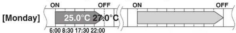
text_image
[Monday] ON OFF 25.0°C 27.0°C 6:00 8:30 17:30 22:00 ON OFFSetting Displays

text_image
MON Day and number ON/OFF Time ON 6:00 Temperature ON 25.0°C1. Press
• The day of the week and the reservation number of the current day will be displayed.
- 1 to 4 settings can be made per day.
2. Press Select to select the desired day of the week and reservation number.
- Pressing Select changes the reservation number and the day of the week.
3. Press Next .
• The day of the week and reservation number will be set.
• “ Ⓧ WEEKLY ” and “ ON ” blink.
4. Press Select to select the desired mode.
- Pressing Select changes the "ON" or "OFF" setting in sequence.

flowchart
graph LR
    A["ON"] --> B["OFF"]
    B --> C["blank"]
    style A fill:#f9f,stroke:#333
    style B fill:#f9f,stroke:#333
    style C fill:#ccf,stroke:#333
Pressing Select puts the sequence in reverse.
- In case the reservation has already been set, selecting "blank" deletes the reservation.
- Proceed to STEP 9 if "blank" is selected.
- To return to the day of the week and reservation number setting, press 📄.
5. Press Next .
- The ON/OFF TIMER mode will be set.
• “WEEKLY” and the time blink.
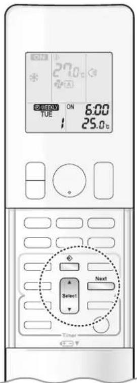
text_image
27.0°C ON 6:00 TUE 25.0°C Select Next Timer6. Press to select the desired time.
- The time can be set between 0:00 and 23:50 in 10-minute intervals.
- To return to the ON/OFF TIMER mode setting, press Back
- Proceed to STEP 9 when setting the OFF TIMER.
7. Press Next
• The time will be set.
• “ ⏻ WEEKLY ” and the temperature blink.
8. Press to select the desired temperature.
• The temperature can be set between 10.0^ C and 32.0^ C.
COOL or AUTO: The unit operates at 18.0°C even if it is set to 10.0°C to 17.0°C. ▶Page 11
HEAT or AUTO : The unit operates at 30.0°C even if it is set to 31.0°C to 32.0°C. ▶Page 11
• To return to the time setting, press Back
- The set temperature is only displayed when the mode setting is on.
9. Press Next
- The temperature will be set and go to the next reservation setting.
- The temperature is set while in ON TIMER operation, and the time is set while in OFF TIMER operation.
• The next reservation screen will appear.
• To continue further settings, repeat the procedure from STEP 4.
10. Press to complete the setting.
- Be sure to direct the remote controller toward the indoor unit and check for a receiving tone and blinking of the OPERATION lamp.
- “WEEKLY” appears on the LCD and WEEKLY TIMER operation is activated.
• The TIMER lamp lights orange.
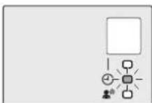
Display
- A reservation made once can be easily copied and the same settings used for another day of the week. Refer to Copy mode. ▶Page 25
NOTE
Notes on WEEKLY TIMER operation
- Do not forget to set the clock on the remote controller first. ▶Page 10
- The day of the week, ON/OFF TIMER mode, time and set temperature (only for ON TIMER mode) can be set with the WEEKLY TIMER. Other settings for the ON TIMER are based on the settings just before the operation.
- WEEKLY TIMER and ON/OFF TIMER operation cannot be used at the same time. The ON/OFF TIMER operation has priority if it is set while WEEKLY TIMER is still active. The WEEKLY TIMER will enter the standby state, and “WEEKLY” will disappear from the LCD. When the ON/OFF TIMER is up, the WEEKLY TIMER will automatically become active.
- Only the time and set temperature with the WEEKLY TIMER are sent with the ☐. Set the WEEKLY TIMER only after setting the operation mode, the airflow rate and the airflow direction ahead of time.
- Turning off the circuit breaker, power failure, and other similar events will render operation of the indoor unit's internal clock inaccurate. Reset the clock. ▶Page 10
- can be used only for the time and temperature settings. It cannot be used to go back to the reservation number.

WEEKLY TIMER Operation

text_image
27.8°C ON 6:00 TUE 1 25.0°C Copy Select TimerCopy mode
- A reservation made once can be copied to another day of the week. The whole reservation of the selected day of the week will be copied.
Programme 1 Programme 2 Programme 3 Programme 4

text_image
[Monday] ON OFF ON OFF 25.0°C 27.0°C 6:00 8:30 17:30 22:00 COPYProgramme 1 Programme 2 Programme 3 Programme 4
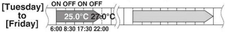
text_image
[Tuesday] to [Friday] ON OFF ON OFF 25.0°C 27.0°C 6:00 8:30 17:30 22:00Setting Displays

text_image
27.0°C ON 6:00 MON 25.0°C Confirmation Copy Paste CP ON 6:00 TUE Normal CP ON 6:00 TUE 25.0°C ON 15:30 27.0°C ON 15:30-
Press
-
Press Select to confirm the day of the week to be copied.
-
Press Copy .
- The whole reservation of the selected day of the week will be copied.
-
Press Select to select the destination day of the week.
-
Press Copy .
- The reservation will be copied to the selected day of the week. The whole reservation of the selected day of the week will be copied.
• To continue copying the settings to other days of the week, repeat STEP 4 and STEP 5.
- Press ☐ to complete the setting.
- “WEEKLY” appears on the LCD and WEEKLY TIMER operation is activated.
NOTE
Note on COPY MODE
- The entire reservation of the source day of the week is copied in the copy mode. In the case of making a reservation change for any day of the week individually after copying the content of weekly reservations, press and change the settings in the steps of Setting mode. ▶Page 23
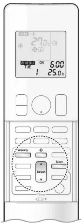
text_image
27.0 ON 6:00 TUE 25.0°C Weekly Select Next Time■ Confirming a reservation
• The reservation can be confirmed.
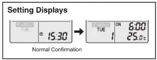
text_image
Setting Displays TUE 15:30 Normal Confirmation TUE ON 6:00 25.0°C1. Press
- The day of the week and the reservation number of the current day will be displayed.
2. Press to select the day of the week and the reservation number to be confirmed.
- Pressing displays the reservation details.
- To change the confirmed reserved settings, select the reservation number and press. The mode is switched to setting mode. Proceed to Setting mode STEP 4. ▶Page 23
3. Press to exit the confirmation mode.
- “ WEEKLYrs on the LCD and WEEKLY TIMER operation is activated.
• The TIMER lamp lights orange.

Display
■ To deactivate WEEKLY TIMER operation
Press ☐ while “ Ⓧ WEEKLY ” is displayed on the LCD.
• “WEAR bears from the LCD.
• The TIMER lamp goes off.
• To reactivate the WEEKLY TIMER operation, press ____ again.
- If a reservation deactivated with weekly is activated once again, the last reservation mode will be used.
NOTE
- If not all the reservation settings are reflected, deactivate the WEEKLY TIMER operation once. Then press ____ again to reactivate the WEEKLY TIMER operation.

WEEKLY TIMER Operation

text_image
27.0°C ON 6:00 TUE 25.0°C Weekly Select Next Timer■ To delete a reservation
An individual reservation
1. Press
- The day of the week and the reservation number will be displayed.
2. Press to select the day of the week and the reservation number to be deleted.
3. Press Next
- “ WEEKLY ” or “ Oblink. OFF
4. Press until no icon is displayed.
- Pressing changes the ON/OFF TIMER mode in sequence.
- Selecting "blank" will cancel any reservation you may have.
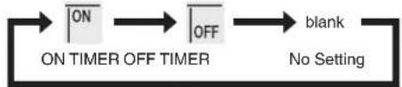
flowchart
graph LR
    A["ON"] --> B["OFF"]
    B --> C["blank"]
    D["ON TIMER OFF TIMER"] --> E["No Setting"]
Pressing Select puts the sequence in reverse.
5. Press Next .
- The selected reservation will be deleted.
6. Press
- If there are still other reservations, WEEKLY TIMER operation will be activated.
Reservations for each day of the week
- This function can be used for deleting reservations for each day of the week.
- It can be used while confirming or setting reservations.
1. Press
- The day of the week and the reservation number will be displayed.
2. Press Select to select the day of the week to be deleted.
3. Hold for about 5 seconds.
- The reservation of the selected day of the week will be deleted.
4. Press
- If there are still other reservations, WEEKLY TIMER operation will be activated.
All reservations
Hold Weekly for about 5 seconds with the normal display.
- Be sure to direct the remote controller toward the indoor unit and check for a receiving tone.
- This operation cannot be used for the WEEKLY TIMER setting display.
- All reservations will be deleted.
Care and Cleaning

CAUTION
- Before cleaning, be sure to stop the operation and turn off the circuit breaker.
- Do not touch the aluminum fins of the indoor unit. If you touch those parts, this may cause an injury.
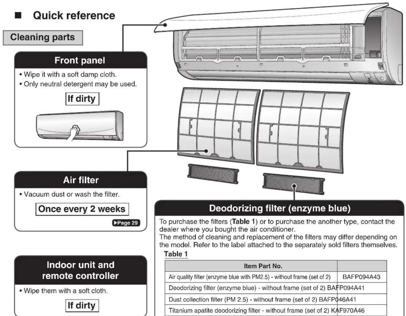
text_image
Quick reference Cleaning parts Front panel • Wipe it with a soft damp cloth. • Only neutral detergent may be used. If dirty Air filter • Vacuum dust or wash the filter. Once every 2 weeks ▶Page 29 Indoor unit and remote controller • Wipe them with a soft cloth. If dirty Deodorizing filter (enzyme blue) To purchase the filters (Table 1) or to purchase the another type, contact the dealer where you bought the air conditioner. The method of cleaning and replacement of the filters may differ depending on the model. Refer to the label attached to the separately sold filters themselves. Table 1 Item Part No. Air quality filter (enzyme blue with PM2.5) - without frame (set of 2) BAFP094A43 Deodorizing filter (enzyme blue) - without frame (set of 2) BAFP094A41 Dust collection filter (PM 2.5) - without frame (set of 2) BAFP046A41 Titanium apatite deodorizing filter - without frame (set of 2) KAF970A46NOTE
Deodorizing filter (enzyme blue), Titanium apatite deodorizing filter.
• Vacuum dust or replace the filter.
[Cleaning] [Replacement]
Once every 6 months Once every 3 years
Page 30
▶Page 30
Air quality filter (enzyme blue with PM2.5), Dust collection filter (PM 2.5)
- No cleaning is required. Please replace the filter every 6 months. ▶Page 30
For cleaning, do not use any of the following:
• Water hotter than 40°C
• Volatile liquid such as benzene, petrol and thinner
- Polishing compounds
- Rough materials such as a scrubbing brush

natural_image
Illustration of a kettle, a tray, and a bottle (no text or symbols)Care and Cleaning
Air filter
1. Open the front panel.
- Hold the front panel by the sides and open it.

natural_image
Diagram of an air conditioner unit showing airflow direction and component layout (no text or symbols)2. Pull out the air filters.
- Push the filter tab at the centre of each air filter a little upwards, then pull it down.
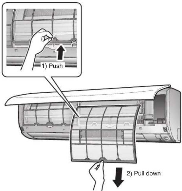
text_image
1) Push 2) Pull down3. Wash the air filters with water or clean them with vacuum cleaner.
- It is recommended to clean the air filters every 2 weeks.

natural_image
Illustration of hands holding a grid-based device with a tool, no text or symbols visibleIf the dust does not come off easily
- Wash the air filters with neutral detergent thinned with lukewarm water, then dry them up in the shade.
- Be sure to remove the filter (small). Refer to "Filter (small)" on the next page.
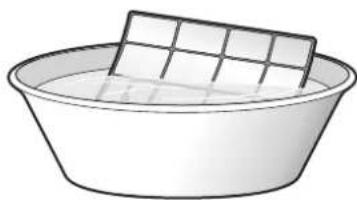
natural_image
Simple line drawing of a basin with a rectangular plate on top (no text or symbols)4. Reattach the filters.
5. Close the front panel slowly.
- Press the panel at both sides and the centre.

natural_image
Illustration of a car air conditioner with airflow arrows indicating airflow direction (no text or symbols)- Make sure that the front panel is securely fixed.
■ Filter (small)
* For the applicable filter type, please refer to ▶Page 28.
Attaching
-
Open the front panel and pull out the air filters. ▶Page 29
-
Insert the filter.
- Check that the filters are inserted securely under the tabs.
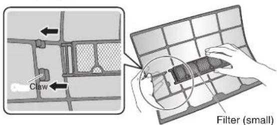
text_image
Claw Filter (small)Cleaning and Replacement
-
Open the front panel and pull out the air filters. ▶Page 29
-
Take off the filter.
-
Hold the recessed parts of the frame and unhook the 4 claws.
- Remove the filters from the tabs.

text_image
Claw Filter (small)- Clean or replace.
[Cleaning]
Deodorizing filter (enzyme blue) : Blue / Titanium apatite deodorizing filter : Blue-Black
3-1 Vacuum dust, and soak in lukewarm water or water for about 10 to 15 minutes if very dirty.
3-2 After washing, shake off remaining water and let them dry in the shade.
- This filter can be renewed by washing it with water once every 6 months and we recommend replacing it once every 3 years.
- Do not wiring out the filter when removing water from it.
Air quality filter (enzyme blue with PM2.5) : Blue-White / Dust collection filter (PM 2.5) : White
- Do not wash the filters as this will reduce their efficiency.
- It is recommended to replace it once every 6 months.
[Replacement]
Remove the filter from the filter frame and prepare a new one.
- Do not throw away the filter frame.
Reuse the filter frame when replacing the filter. - When attaching the filter, check that the filter is properly set in the tabs.

- Set the filters as they were and close the front panel.
- Press the front panel at both sides and the center.
NOTE
• Operation with dirty filters:
- cannot deodorise the air,
- cannot clean the air,
– results in poor heating or cooling,
- may cause odour.
- Dispose of old filters as non-flammable waste.
Care and Cleaning
■ Prior to a long period of non-use
- Operate the FAN mode for several hours on a fine day to dry out the inside.
1) Press and select "".
2) Press ⏻ and start the operation.
- After operation stops, turn off the circuit breaker for the room air conditioner.
- Clean the air filters and reattach them. ▶Page 29
- To prevent battery leakage, take out the batteries from the remote controller.
■ We recommend periodical maintenance
- In certain operating conditions, the inside of the air conditioner may get foul after several seasons of use, resulting in poor performance. It is recommended to have periodical maintenance by a specialist in addition to regular cleaning by the user.
- For specialist maintenance, please contact the dealer where you bought the air conditioner.
- The maintenance cost must be borne by the user.
FAQ
Indoor unit
The flaps do not start swinging immediately.
- The air conditioner is adjusting the position of the flaps. The flaps will start moving soon.
The air conditioner stops generating airflow during HEAT operation.
- Once the set temperature is reached, the airflow rate is reduced and operation stopped in order to avoid generating a cool airflow. Operation will resume automatically when the indoor temperature falls.
HEAT operation stops suddenly and a flowing sound is heard.
- The outdoor unit is defrosting. HEAT operation starts after the frost on the outdoor unit has been removed. This can take about 4 to 12 minutes.
Operation does not start soon.
■ When ⏻ was pressed soon after operation was stopped.
■ When the mode was reselected.
• This is to protect the air conditioner. You should wait for about 3 minutes.
Outdoor unit
The outdoor unit emits water or steam.
In HEAT operation
- The frost on the outdoor unit melts into water or steam when the air conditioner is in defrosting operation.
■ In COOL or DRY operation
- Moisture in the air condenses into water on the cool surface of the outdoor unit piping and drips.
Different sounds are heard.
■ A sound like flowing water
- This sound is generated because the refrigerant in the air conditioner is flowing.
- This is a pumping sound of the water in the air conditioner and can be heard when the water is pumped out from the air conditioner during COOL or DRY operation.
■ Blowing sound
- This sound is generated when the flow of the refrigerant in the air conditioner is switched over.
■ Ticking sound
- This sound is generated when the cabinet and frame of the air conditioner slightly expand or shrink as a result of temperature changes.
■ Whistling sound
- This sound is generated when refrigerant flows during defrosting operation.
- Clicking sound during operation or idle time
- This sound is generated when the refrigerant control valves or the electrical parts operate.
■ Clopping sound
- This sound is heard from the inside of the air conditioner when the exhaust fan is activated while the room doors are closed. Open the window or turn off the exhaust fan.
■ Rotating machinery causes sound
- Sound is heard when the vertical swing flaps and the horizontal swing flaps move.
- When the air conditioner is operating in a quiet environment and the airflow rate of the indoor unit is set to Quiet Mode or Low Mode, the motion of the swing flaps may cause sound.
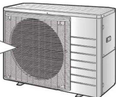
natural_image
Illustration of a large industrial air conditioning unit with cooling fan and ventilation grilles (no text or symbols)Troubleshooting
Before making an inquiry or a request for repair, please check the following.
If the problem persists, consult your dealer.

Not a problem
This case is not a problem.

Check
Please check again before requesting repairs.
The air conditioner does not operate
| Case Description / what to check | |
| OPERATION lamp is off. | Has the circuit breaker been tripped or the fuse blown?Is there a power failure?Are batteries set in the remote controller? |
| OPERATION lamp is blinking. | Turn off the power with the circuit breaker and restart operation with the remote controller.If the OPERATION lamp is still blinking, check the error code and consult your dealer. |
The air conditioner suddenly stops operating
| Case Description / what to check | |
| OPERATION lamp is on. | To protect the system, the air conditioner may stop operating after sudden large voltage fluctuations. It automatically resumes operation in about 3 minutes. |
| OPERATION lamp is blinking. | Is there anything blocking the air inlet or air outlet of the indoor unit or outdoor unit?Stop operation and after turning off the circuit breaker, remove the obstruction. Then restart operation with the remote controller. If the OPERATION lamp is still blinking, check the error code and consult your dealer.Page 36Are operation modes all the same for indoor units connected to the outdoor unit in the multi system? If not, set all indoor units to the same operation mode and confirm that the lamps blink.If the lamps stop blinking after the above steps, there is no malfunction. |
The air conditioner does not stop operating
| Case Description / what to check | |
| The air conditioner continues operating even after operation is stopped. | ☑ Immediately after the air conditioner is stopped• The outdoor unit fan continues rotating for about another 1 minute to protect the system.• While the air conditioner is not in operation• When the outdoor temperature is high, the outdoor unit fan may start rotating to protect the system. |
The room does not cool down / warm up
| Case Description / what to check | |
| Air does not come out. | ☑ In HEAT operationThe air conditioner is warming up. Wait for about 1 to 4 minutes.During defrosting operation, hot air does not flow out of the indoor unit.When the air conditioner operates immediately after the circuit breaker is turned onThe air conditioner is preparing to operate. Wait for about 3 to 15 minutes. |
| Air does not come out / Air comes out. | ? Is the airflow rate setting appropriate?Is the airflow rate setting low, such as “Indoor unit quiet” or “Airflow rate 1”? Increase the airflow rate setting.Is the set temperature appropriate?Is the adjustment of the airflow direction appropriate? |
| Air comes out. | ? Is there any furniture directly under or beside the indoor unit?Is the air conditioner in ECONO operation or OUTDOOR UNIT QUIET operation? ▶Page 18Are the air filters dirty?Is there anything blocking the air inlet or air outlet of the indoor unit or outdoor unit?Is a window or door open?Is an exhaust fan turning? |
Mist comes out
| Case Description / what to check | |
| Mist comes out of the indoor unit. | This happens when the air in the room is cooled into mist by the cold airflow during COOL or other operation. |
Remote controller
| Case Description / what to check | |
| The unit does not receive signals from the remote controller or has a limited operating range. | The batteries may be exhausted.Replace both batteries with new dry batteries AAA.LR03 (alkaline).For details, refer to “Preparation Before Operation”. ▶Page 9Signal communication may be disabled if an electronic-starter-type fluorescent lamp (such as inverter-type lamps) is in the room. Consult your dealer if that is the case.The remote controller may not function correctly if the transmitter is exposed to direct sunlight. |
| LCD is faint, is not working, or the display is erratic. | The batteries may be exhausted.Replace both batteries with new dry batteries AAA.LR03 (alkaline).For details, refer to “Preparation Before Operation”. ▶Page 9 |
| The LCD is blinking and the remote controller cannot be operated. | Battery power has run out.Replace both batteries at the same time with new size AAA.LR03 (alkaline) batteries.Leaving exhausted batteries in the remote controller can result in injury due to battery leakage, rupturing or heating, or lead to equipment failure.(Even when the LCD is blinking, the OFF button remains functional.) |
| Other electric devices start operating. | If the remote controller activates other electric devices, move them away or consult your dealer. |
Air has an odour
| Case Description / what to check | |
| The air conditioner gives off an odour. | The room odour absorbed in the unit is discharged with the airflow.We recommend you to have the indoor unit cleaned. Please consult your dealer. |
Others
| Case Description / what to check | |
| The air conditioner suddenly starts behaving strangely during operation. | The air conditioner may malfunction due to lightning or radio.If the air conditioner malfunctions, turn off the power with the circuit breaker and restart the operation with the remote controller. |
| The ON/OFF TIMER does not operate according to the settings. | Check if the ON/OFF TIMER and the WEEKLY TIMER are set to the same time.Change or deactivate the settings in the WEEKLY TIMER. ▶Page 22 |
NOTE
Notes on the operating conditions
- If operation continues under any conditions other than those listed in the table,
- A safety device may activate to stop the operation.
- Dew may form on the indoor unit and drip from it when COOL or DRY operation is selected.
| Mode Operating conditions | |
| COOL / DRY | Outdoor temperature: -10.0~46.0°CIndoor temperature: 18.0~32.0°CIndoor humidity: 80% max. |
| HEAT | Outdoor temperature: -15.0~24.0°CIndoor temperature: 10.0~30.0°C |
■ Call your dealer immediately

WARNING
When an abnormality (such as a burning smell) occurs, stop operation and turn off the circuit breaker.
- Continued operation in an abnormal condition may result in problems, electric shock or fire.
- Consult the dealer where you bought the air conditioner.
Do not attempt to repair or modify the air conditioner by yourself.
- Incorrect work may result in electric shock or fire.
- Consult the dealer where you bought the air conditioner.
If one of the following symptoms takes place, call your dealer immediately.
- The power cord is abnormally hot or damaged.
- An abnormal sound is heard during operation.
- The circuit breaker, a fuse, or the earth leakage circuit breaker cuts off the operation frequently.
- A switch or a button often fails to work properly.
• There is a burning smell.
• Water leaks from the indoor unit.
Turn off the circuit breaker and call your dealer.

■ After a power failure
Lightning
- The air conditioner automatically resumes operation in about 3 minutes. Please wait for a while.
- If there is a risk lightning could strike in the neighbourhood, stop operation and turn off the circuit breaker to protect the system.
■ Disposal requirements
- Dismantling of the unit, handling of the refrigerant, oil and other parts, should be done in accordance with the relevant local and national regulations.
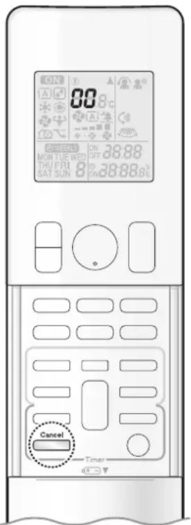
text_image
ON 88.8°C ON MON TUR WED ON 38:88 THU FRI ON 38:88 SAT SUN 8 ON 38:88 SE Cancel Timer■ Fault diagnosis by remote controller
- In case the air conditioner is malfunctioning, you can check the error code via the remote controller before consulting with service personnel and informing them of the malfunction code.
1. When Cancel is held down for about 5 seconds, "00" blinks in the temperature display section.
2. Press Cancel repeatedly until a long beep is produced.
- The code indication changes as shown below, and notifies you with a long beep.
| CODE MEANING | ||
| SYSTEM | 00 NORMAL | |
| UA INDOOR-OUTDOOR UNIT COMBINATION FAULT | ||
| U0 REFRIGERANT SHORTAGE | ||
| U2 DROP VOLTAGE OR MAIN CIRCUIT OVERVOLTAGE | ||
| U4 FAILURE OF TRANSMISSION (BETWEEN INDOOR UNIT AND OUTDOOR UNIT) | ||
| INDOOR UNIT | A1 INDOOR PCB DEFECTIVENESS | |
| A5 HIGH PRESSURE CONTROL OR FREEZE-UP PROTECTOR | ||
| A6 FAN MOTOR FAULT | ||
| C4 FAULTY HEAT EXCHANGER TEMPERATURE SENSOR | ||
| C9 FAULTY SUCTION AIR TEMPERATURE SENSOR | ||
| OUTDOOR UNIT | EA | COOLING-HEATING SWITCHING ERROR |
| E1 CIRCUIT BOARD FAULT | ||
| E5 OL STARTED | ||
| E6 FAULTY COMPRESSOR START UP | ||
| E7 DC FAN MOTOR FAULT | ||
| E8 OVERCURRENT INPUT | ||
| F3 HIGH TEMPERATURE DISCHARGE PIPE CONTROL | ||
| F6 HIGH PRESSURE CONTROL (IN COOLING) | ||
| H0 SENSOR FAULT | ||
| H6 OPERATION HALT DUE TO FAULTY POSITION DETECTION SENSOR | ||
| H8 DC CURRENT SENSOR FAULT | ||
| H9 FAULTY SUCTION AIR TEMPERATURE SENSOR | ||
| J3 | FAULTY DISCHARGE PIPE TEMPERATURE SENSOR | |
| J6 | FAULTY HEAT EXCHANGER TEMPERATURE SENSOR | |
| L3 ELECTRICAL PARTS HEAT FAULT | ||
| L4 HIGH TEMPERATURE AT INVERTER CIRCUIT HEATSINK | ||
| L5 OUTPUT OVERCURRENT | ||
| P4 FAULTY INVERTER CIRCUIT HEATSINK TEMPERATURE SENSOR | ||
NOTE
- A short beep and 2 consecutive beeps indicates non-corresponding codes.
- To cancel the code display, hold down for about 5 seconds. The code display also clears if no button is pressed for 1 minute.
MEMO
Quick Reference
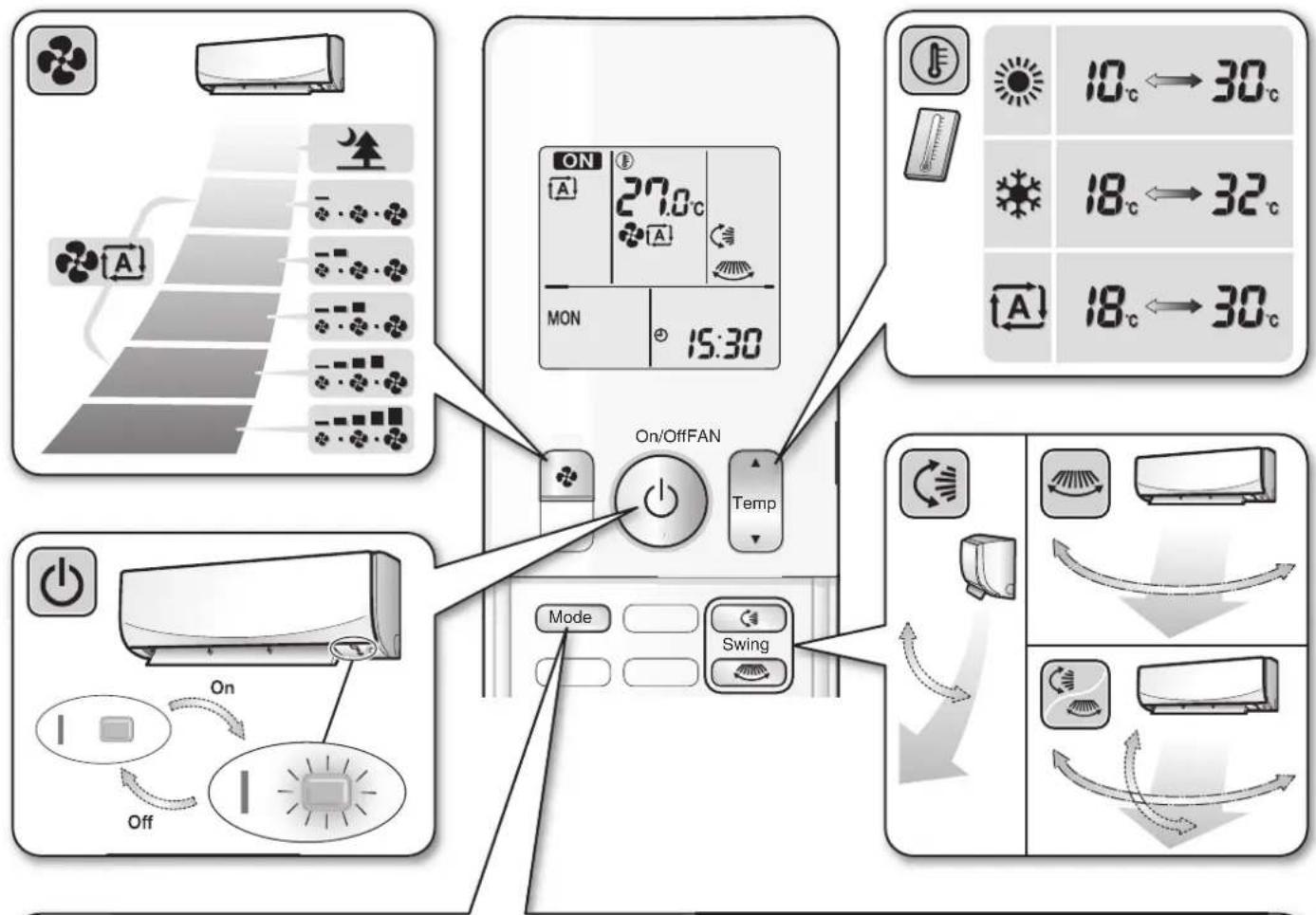
text_image
ON 27.0°C MON 15:30 On/OffFAN Temp Mode Swing 10°C ← 30°C 18°C ← 32°C 18°C ← 30°C
flowchart
graph TD
    A["MODE"] --> B["A"]
    B --> C["Temperature Control"]
    C --> D["Green Roof"]
    D --> E["% RH"]
    E --> F["Green Roof with Temperature Control"]
    F --> G["Green Roof with Temperature Control"]
    G --> H["Green Roof with Temperature Control"]
    H --> I["Green Roof with Temperature Control"]
    I --> J["Green Roof with Temperature Control"]
    J --> K["Green Roof with Temperature Control"]
    K --> L["Green Roof with Temperature Control"]
    L --> M["Green Roof with Temperature Control"]
    M --> N["Green Roof with Temperature Control"]
    N --> O["Green Roof with Temperature Control"]
    O --> P["Green Roof with Temperature Control"]
    P --> Q["Green Roof with Temperature Control"]
    Q --> R["Green Roof with Temperature Control"]
    R --> S["Green Roof with Temperature Control"]
    S --> T["Green Roof with Temperature Control"]
    T --> U["Green Roof with Temperature Control"]
    U --> V["Green Roof with Temperature Control"]
    V --> W["Green Roof with Temperature Control"]
    W --> X["Green Roof with Temperature Control"]
    X --> Y["Green Roof with Temperature Control"]
    Y --> Z["Green Roof with Temperature Control"]
    Z --> AA["Green Roof with Temperature Control"]
    AA --> AB["Green Roof with Temperature Control"]
    AB --> AC["Green Roof with Temperature Control"]
    AC --> AD["Green Roof with Temperature Control"]
    AD --> AE["Green Roof with Temperature Control"]
    AE --> AF["Green Roof with Temperature Control"]
    AF --> AG["Green Roof with Temperature Control"]
    AG --> AH["Green Roof with Temperature Control"]
    AH --> AI["Green Roof with Temperature Control"]
    AI --> AJ["Green Roof with Temperature Control"]
    AJ --> AK["Green Roof with Temperature Control"]
    AK --> AL["Green Roof with Temperature Control"]
    AL --> AM["Green Roof with Temperature Control"]
    AM --> AN["Green Roof with Temperature Control"]
    AN --> AO["Green Roof with Temperature Control"]
    AO --> AP["Green Roof with Temperature Control"]
    AP --> AQ["Green Roof with Temperature Control"]
    AQ --> AR["Green Roof with Temperature Control"]
    AR --> AS["Green Roof with Temperature Control"]
    AS --> AT["Green Roof with Temperature Control"]
    AT --> AU["Green Roof with Temperature Control"]
    AU --> AV["Green Roof with Temperature Control"]
    AV --> AW["Green Roof with Temperature Control"]
    AW --> AX["Green Roof with Temperature Control"]
    AX --> AY["Green Roof with Temperature Control"]
DAIKIN INDUSTRIES, LTD.
Head office:
Umeda Center Bldg., 2-4-12, Nakazaki-Nishi,
Kita-ku, Osaka, 530-8323 Japan
Tokyo office:
JR Shinagawa East Bldg., 2-18-1, Konan,
Minato-ku, Tokyo, 108-0075 Japan
https://www.daikin.com

The two-dimensional bar code is a manufacturing code.
OPERATION MANUAL
DAIKIN ROOM AIR CONDITIONER
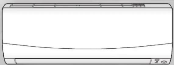
natural_image
Line drawing of a single air conditioner unit (no text or symbols)MODELS
FTKM20Q2VMA
FTKM25Q2VMA
FTKM35Q2VMA
FTKM46Q2VMA

natural_image
Illustration of a city skyline above Earth with continents and oceans (no text or symbols)Features
Enhanced comfort and energy savings
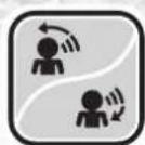
INTELLIGENT EYE
The INTELLIGENT EYE sensor detects human movement and adjusts the right and left airflow direction. If no one is in the room for more than 20 minutes, the operation automatically changes to energy saving operation. The INTELLIGENT EYE sensor works differently depending on the situation. ▶ Page 16

WEEKLY TIMER
Up to 4 timer settings can be saved for each day of the week according to your family's life style. The WEEKLY TIMER allows you to set on/off times and the desired temperature. ▶ Page 23
Other functions

COMFORT AIRFLOW OUTDOOR UNIT QUIET
The airflow direction is upward while in COOL operation, and downward while in HEAT operation. This function prevents cold or warm air from blowing directly on your body. ▶ Page 15

OUTDOOR UNIT QUIET operation assures a low noise level of the outdoor unit. This function is useful to maintain a quiet neighbourhood.
Page 19
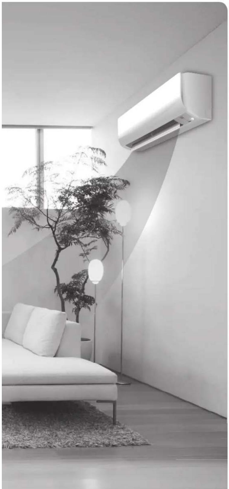
natural_image
Modern minimalist living room interior with white sofa, wall-mounted air conditioner, and potted plant (no text or symbols visible)
ECONO
This function enables efficient operation by limiting the maximum power consumption. It is useful when using the air conditioner and other electrical devices simultaneously on a shared electrical circuit. Page 19
Contents
Read Before Operation
Safety Precautions 3
Names of Parts 5
Preparation Before Operation 9
Basic Operation

DRY · COOL · FAN Operation...... 11

Adjusting the Airflow Direction...... 13

Adjusting the Airflow Rate...... 14
Useful Functions

COMFORT AIRFLOW Operation.....15

INTELLIGENT EYE Operation...... 16

POWERFUL Operation.... 18

ECONO/OUTDOOR UNIT QUIET Operation.... 19
TIMER Operation

ON/OFF TIMER Operation...... 20

WEEKLY TIMER Operation......23
Care
Care and Cleaning 29
■ When the Need Arises
FAQ 34
Troubleshooting 35
Safety Precautions
Read the precautions in this manual carefully before operating the unit.

This appliance is filled with R32.
- Keep this manual where the user can easily find it.
- The precautions described herein are classified as WARNING and CAUTION. They both contain important information regarding safety. Be sure to observe all precautions without fail.

WARNING
Failure to follow these instructions properly may result in personal injury or loss of life.

CAUTION
Failure to follow these instructions properly may result in property damage or personal injury, which may be serious depending on the circumstances.

Never attempt.

Be sure to follow the instructions.

Be sure to establish an earth connection.

Never touch the air conditioner nor the remote controller with wet hands.

Never wet the air conditioner nor the remote controller
• After reading, keep this manual in a convenient place so that you can refer to it whenever necessary. If the equipment is transferred to a new user, be sure also to hand over the manual.

WARNING

- Do not use means to accelerate the defrosting process or to clean, other than those recommended by the manufacturer.
- The appliance must be stored in a room without continuously operating ignition sources (for example: open flames, an operating gas appliance or an operating electric heater).
- Do not pierce or burn.
- Be aware that refrigerants may not contain an odour.
- The appliance must be installed, operated and stored in a room with floor area larger than -^*m^2 for 20/25/35/46 class.
* Since the maximum refrigerant charge of the models is below 1.84kg , it does not have any limitation for the minimum floor area.
• To avoid fire, explosion or injury, do not operate the unit when harmful gases (e.g. flammable or corrosive) are detected near the unit. - Be aware that prolonged, direct exposure to cool or warm air from the air conditioner, or to air that is too cool or too warm, can be harmful to your physical condition and health.
- Do not place objects, including rods, your fingers, etc., in the air inlet or outlet. Product damage or personal injury may result due to contact with the air conditioner's high-speed fan blades.
- Do not attempt to repair, dismantle, reinstall or modify the air conditioner yourself as this may result in water leakage, electric shocks or fire hazards.
- Do not use flammable spray near the air conditioner, or otherwise fire may result.
- When the air conditioner is malfunctioning (giving off a burning odour, etc.) turn off power to the unit and contact your local dealer. Continued operation under such circumstances may result in a failure, electric shocks or fire hazards.
- Do not use a refrigerant other than the one indicated on the outdoor unit (R32) when installing, moving or repairing. Using other refrigerants may cause trouble or damage to the unit, and personal injury.

- To avoid electric shocks, do not operate with wet hands.

- Beware of fire in case of refrigerant leakage. If the air conditioner is not operating correctly, i.e. not generating cool or warm air, refrigerant leakage could be the cause. Consult your dealer for assistance. The refrigerant within the air conditioner is safe and normally does not leak.
However, in the event of a leakage, contact with a naked burner, heater or cooker may result in generation of noxious gas. Do not use the air conditioner until a qualified service person confirms that the leakage has been repaired.
- Do not attempt to install or repair the air conditioner yourself. Improper workmanship may result in water leakage, electric shocks or fire hazards. Please contact your local dealer or qualified personnel for installation and maintenance work.
- If the air conditioner is malfunctioning (giving off a burning odour, etc.), turn off power to the unit and contact your local dealer. Continued operation under such circumstances may result in a failure, electric shocks or fire hazards.
- Be sure to install an earth leakage circuit breaker. Failure to install an earth leakage circuit breaker may result in electric shocks or fire.
- Be sure to earth the unit. Do not earth the unit to a utility pipe, lightning conductor or telephone earth lead. Imperfect earthing may result in electric shocks.

CAUTION

- Do not use the air conditioner for purposes other than those for which it is intended. Do not use the air conditioner for cooling precision instruments, food, plants, animals or works of art as this may adversely affect the performance, quality and/or longevity of the object concerned.
- Do not expose plants or animals directly to the airflow from the unit as this may cause adverse effects.
- Do not place appliances that produce naked flames in places exposed to the airflow from the unit as this may impair combustion of the burner.

CAUTION

- Do not block the air inlets nor outlets. Impaired airflow may result in insufficient performance or trouble.
- Do not sit on the outdoor unit, put things on the unit, or pull the unit. Doing so may cause accidents, such as falling or toppling down, thus resulting in injury, product malfunctioning, or product damage.
- Do not give impact to the indoor and outdoor units, or otherwise product damage may result.
- Do not place objects that are susceptible to moisture directly beneath the indoor or outdoor units. Under certain conditions, condensation on the main unit or refrigerant pipes, air filter dirt or drain blockage may cause dripping, resulting in fouling or failure of the object concerned.
- After prolonged use, check the unit stand and its mounts for damage. If they are left in a damaged condition, the unit may fall and cause injury.
- To avoid injury, do not touch the air inlet or aluminium fins of the indoor or outdoor units.
- The appliance is not intended for use by unattended young children or infirm persons. Impairment of bodily functions and harm to health may result.
- Children should be supervised to ensure that they do not play with the unit or its remote controller. Accidental operation by a child may result in impairment of bodily functions and harm health.
- Do not place flammable items, such as spray cans, within 1m of the air outlet.
The spray cans may explode as a result of hot air from the indoor or outdoor units. - Be careful not to let pets urinate on the air conditioner. Urination on the air conditioner may result in electric shocks or fire.
- Do not sit or hang on the panel. The panel may fall, and injury or product malfunctioning may result.
- Do not sway the panel. The panel may hit people or objects, and injury or property damage may result.
- Do not let children play around the panel. Injury or property damage may result.
- Do not pull the wires. The wires may be broken and the panel may fall, and injury or property damage may result.
- Do not locate obstacles in the route. The panel may fall, and injury or property damage may result.
- Do not bend or damage the wires. The wires may be broken and the panel may fall, and injury or property damage may result.
- Do not wash the air conditioner with water, as this may result in electric shocks or fire.
- Do not place water containers (vases, etc.) above the unit, as this may result in electric shocks or fire hazards if they should topple over.
- Do not put objects on the panel, or otherwise production malfunctioning may result.
- Do not use an unstable stand at the time of operating or maintaining the air conditioner, or otherwise you may topple over or injury yourself.
- Locate the remote controller in places out of reach of children. The wrong operation of the remote controller may result in injury.
- To avoid oxygen depletion, ensure that the room is adequately ventilated if equipment such as a burner is used together with the air conditioner.
- Before cleaning, be sure to stop unit operation and turn off the circuit breaker. Otherwise, an electric shock and injury may result.
- Only connect the air conditioner to the specified power supply circuit. Power supplies other than the one specified may result in electric shocks, overheating and fires.
- Arrange the drain hose to ensure smooth drainage. Imperfect drainage may cause wetting of the building, furniture, etc.
- Do not place objects in direct proximity of the outdoor unit and do not let leaves and other debris accumulate around the unit. Leaves are a hotbed for small animals which can enter the unit. Once inside the unit, such animals can cause malfunctions, smoke or fire if they come into contact with electrical parts.
- Do not place objects around the indoor unit.
Doing so may have an adverse influence on the performance, product quality, and life of the air conditioner.

Installation site
■ To install the air conditioner in the following types of environments, consult your dealer.
- Places with an oily environment or where steam or soot occurs.
- Salty environments such as coastal areas.
- Places where sulphide gas occurs such as hot springs.
- Places where snow may block the outdoor unit.
■ Be sure to follow the instructions below.
• The indoor unit is at least 1m away from any television or radio set (unit may cause interference with the picture or sound).
- The drain from the outdoor unit must be discharged to a place of good drainage.
Consider nuisance to your neighbours from noises
■ For installation, choose a place as described below.
- A place solid enough to bear the weight of the unit and which does not amplify the operation noise or vibration.
- A place from where the air discharged from the outdoor unit or the operation noise will not annoy your neighbours.
Electrical work
■ Fdhe power supply, be sure to use a separate power circuit dedicated to the air conditioner.
System relocation
■ Relocating the air conditioner requires specialized knowledge and skills. Please consult your dealer if relocation is necessary for moving or remodelling.
Names of Parts
Indoor Unit
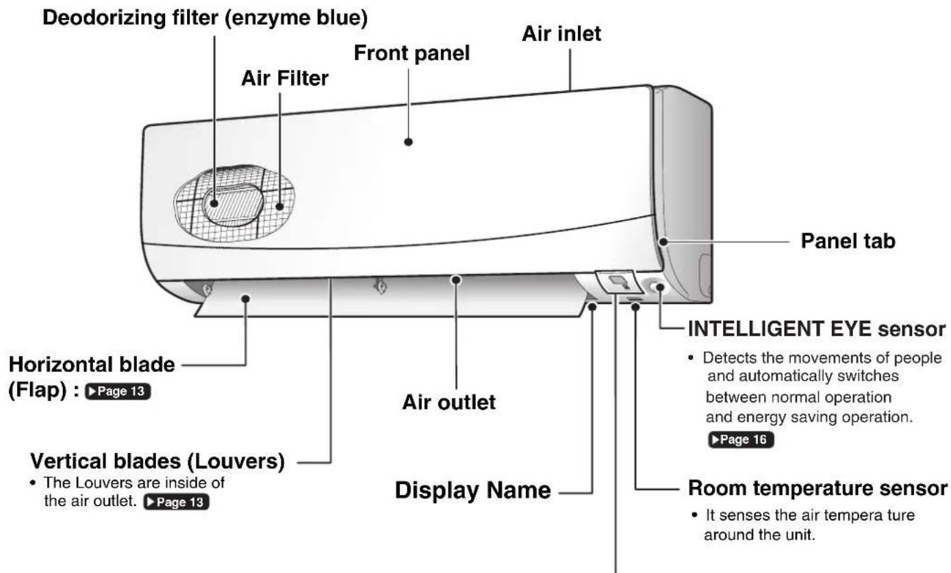
text_image
Deodorizing filter (enzyme blue) Air Filter Front panel Air inlet Horizontal blade (Flap) : ▶Page 13 Vertical blades (Louvers) • The Louvers are inside of the air outlet. ▶Page 13 Air outlet Display Name Panel tab INTELLIGENT EYE sensor • Detects the movements of people and automatically switches between normal operation and energy saving operation. ▶Page 16 Room temperature sensor • It senses the air tempera ture around the unit.Display
Signal receiver
- It receives signals from the remote controller.
- When the unit receives a signal, you will hear a short beep.
• Operation start ...... beep-beep - Settings changed .... beep
• Operation stop ...... beeeeeep

text_image
Operation lamp (green) TIMER lamp (orange) : ▶Page 20,21,22,25,27 ON/OFF INTELLIGENT EYE lamp (green) : ▶Page 16Indoor Unit ON/OFF switch
- Push this switch once to start operation. Push once again to stop it.
- The operation mode refer to the following table.
| Mode | Temperature setting | Airflow rate |
| COOL | 22°C | AUTO |
- This switch can be used when the remote controller is missing.
■ Open the front panel

text_image
Deodorizing filter (enzyme blue) Air filterOutdoor Unit
■ For 20/25/35 class
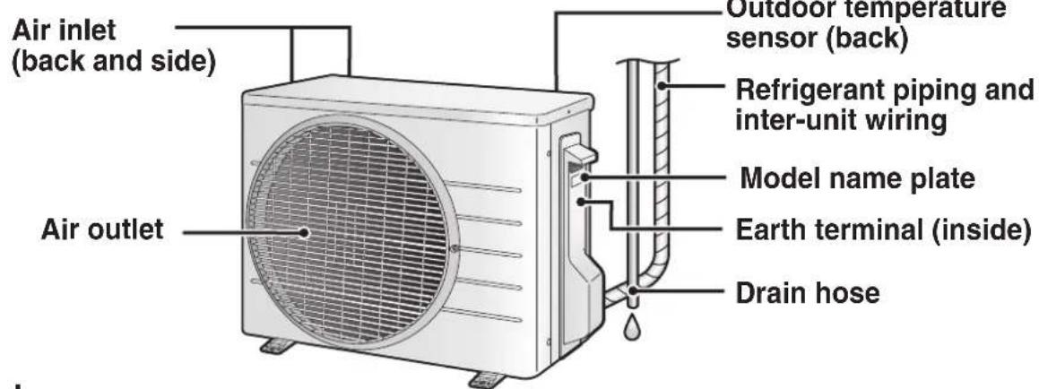
text_image
Air inlet (back and side) Air outlet Outdoor temperature sensor (back) Refrigerant piping and inter-unit wiring Model name plate Earth terminal (inside) Drain hose■ For 46 class

text_image
Air inlet (back and side) Air outlet Outdoor temperature sensor (back) Refrigerant piping and inter-unit wiring Earth terminal (inside) Drain hose Model name plateNames of Parts
Remote Controller
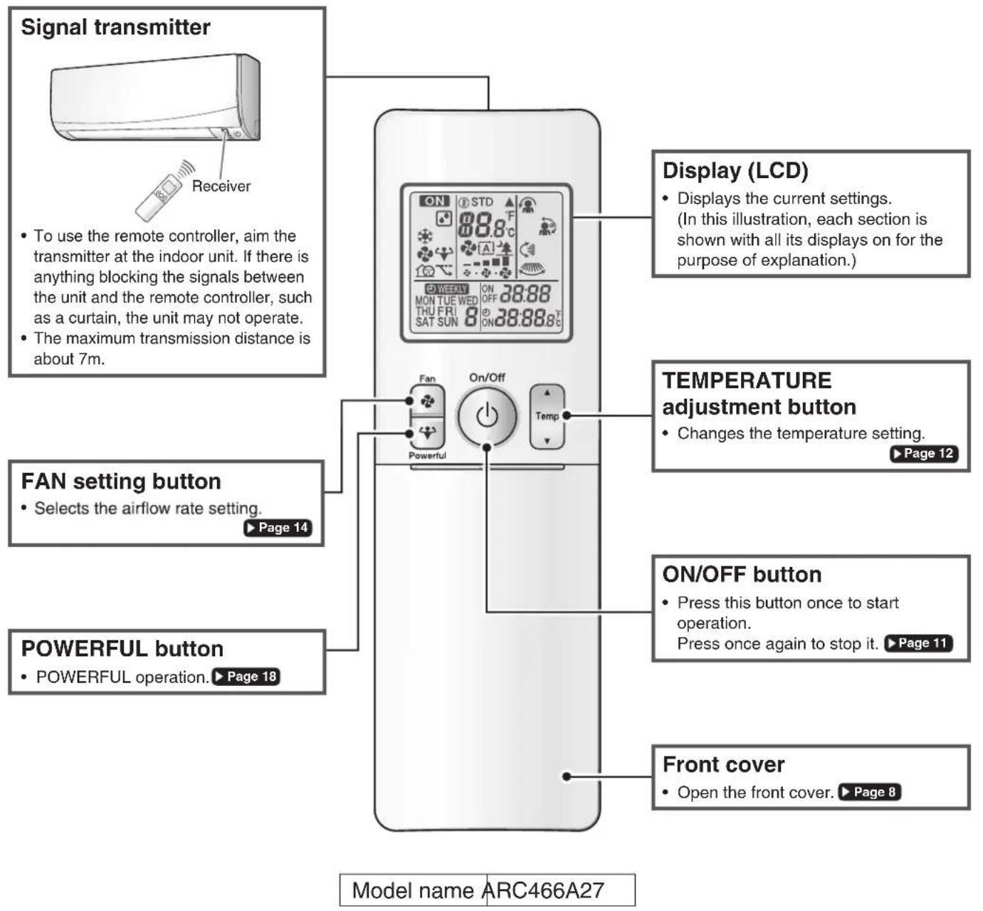
text_image
Signal transmitter Receiver To use the remote controller, aim the transmitter at the indoor unit. If there is anything blocking the signals between the unit and the remote controller, such as a curtain, the unit may not operate. The maximum transmission distance is about 7m. Display (LCD) Displays the current settings. (In this illustration, each section is shown with all its displays on for the purpose of explanation.) TEMPERATURE adjustment button Changes the temperature setting. ▶ Page 12 FAN setting button Selects the airflow rate setting. ▶ Page 14 POWERFUL button POWERFUL operation. ▶ Page 18 ON/OFF button Press this button once to start operation. Press once again to stop it. ▶ Page 11 Front cover Open the front cover. ▶ Page 8 Model name ARC466A27■ Open the front cover
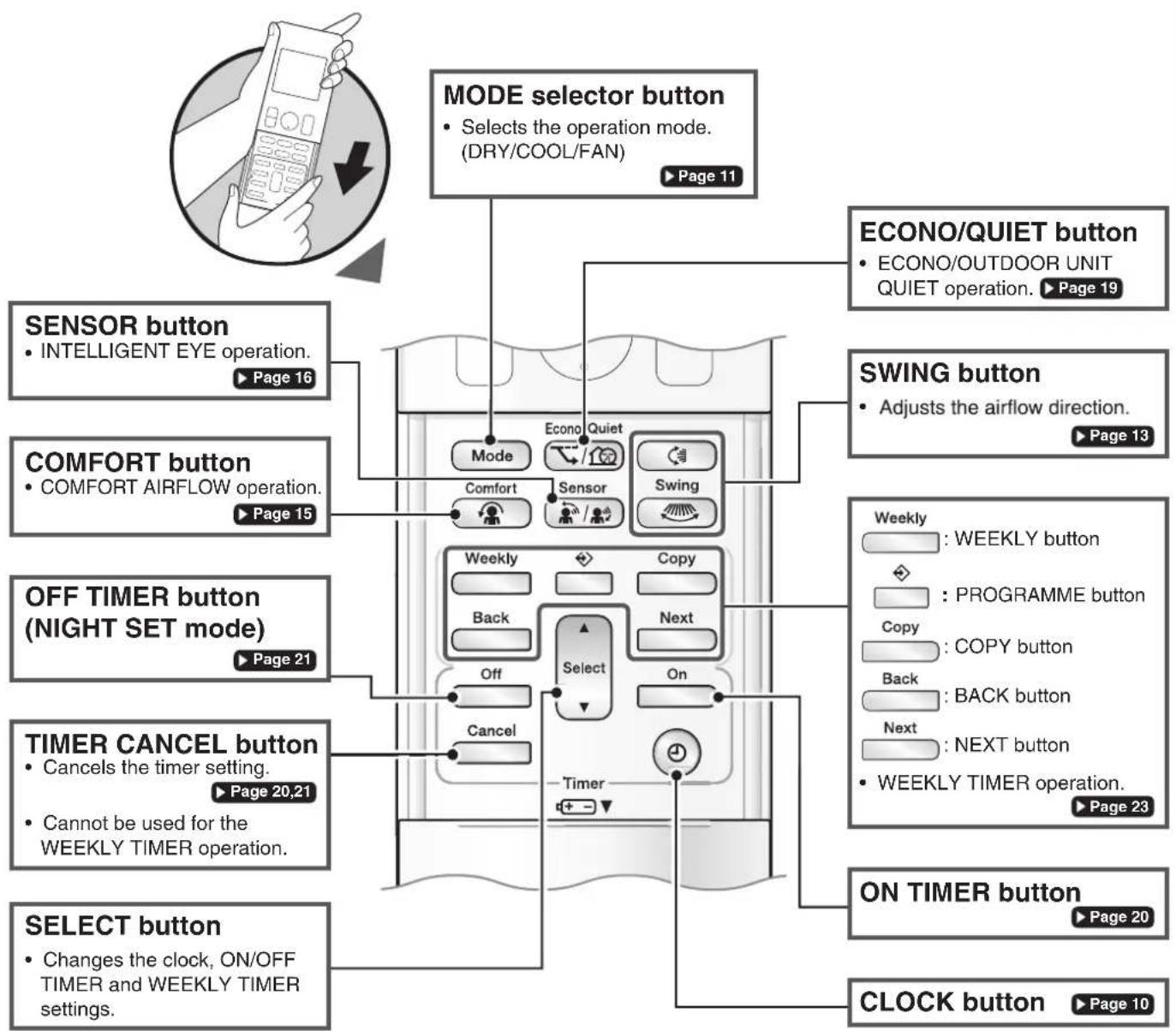
flowchart
graph TD
    A["MODE selector button"] --> B["SENSOR button"]
    A --> C["COMFORT button"]
    A --> D["OFF TIMER button (NIGHT SET mode)"]
    A --> E["TIMER CANCEL button"]
    A --> F["SELECT button"]
    B --> G["ECONO/QUIET button"]
    C --> H["SWING button"]
    D --> I["ON TIMER button"]
    E --> J["CLOCK button"]
    style A fill:#f9f,stroke:#333
    style B fill:#ccf,stroke:#333
    style C fill:#cfc,stroke:#333
    style D fill:#fcc,stroke:#333
    style E fill:#cff,stroke:#333
    style F fill:#ffc,stroke:#333
Preparation Before Operation

text_image
Position + and - correctly!*The remote controller may differ from some models.
To insert the batteries
- Slide the front cover to take it off.
- Insert 2 dry batteries AAA.LR03 (alkaline).
- Replace the front cover.
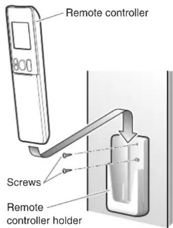
text_image
Remote controller Screws Remote controller holderTo fix the remote controller holder to a wall
- Choose a place from where the signals reach the unit.
- Fix the holder to a wall, a pillar, or similar location with the screws supplied with the holder.
- Place the remote controller in the remote controller holder.
Turn on the circuit breaker
- After the power is turned on, the flaps of the indoor unit open and close once to set the reference position.
NOTE
Notes on batteries
- When replacing the batteries, use batteries of the same type, and replace both old batteries together.
- The batteries will last for about 1 year. If the remote controller display begins to fade and the possible transmission range becomes shorter within a year, however, replace both batteries with new, size AAA.LR03 (alkaline).
- The batteries supplied with the remote controller are for initial operation. The batteries may run out in less than 1 year.
Note on remote controller
- Do not drop the remote controller. Do not get it wet.
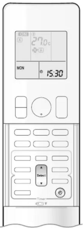
text_image
27.0°C MON 15:30 Select Timer*The remote controller may differ from some models.
To set the clock
1. Press

"0.00 is displayed on the LCD.
"MON" and "④ blink.
2. Press Select to set the current day of the week.
3. Press
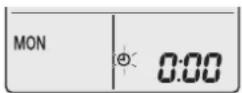
“ @ blinks.
4. Press to set the clock to the present time.
- Holding down ▲ or ▼ rapidly increases or decreases the displayed time.
5. Press
- Point the remote controller at the indoor unit when pressing the buttons.

“*” blinks.
NOTE
Note on setting the clock
- If the indoor unit's internal clock is not set to the correct time, the ON/OFF TIMER and WEEKLY TIMER will not operate punctually.
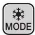
DRY · COOL · FAN Operation

text_image
ON 27.0°C * A MON 15:30 On/Off Mode TimerThe air conditioner operates with the operation mode of your choice.
From the next time on, the air conditioner will operate with the same operation mode.
To start operation
1. Press and select a operation mode.
• Each pressing of the button changes the mode setting in sequence.
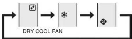
flowchart
graph LR
    A["Start"] --> B["DRY COOL FAN"]
    B --> C["Step 1"]
    C --> D["Step 2"]
    D --> E["Step 3"]
2. Press On/Off
• “ON displayed on the LCD.
• The OPERATION lamp lights green.
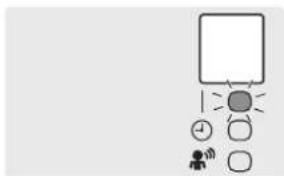
text_image
Simple diagram with a rectangle, lightbulb, clock, and small figures below, possibly representing a system or process.Display
To stop operation
Press again.
- “ On appears from the LCD.
• The OPERATION lamp goes off.
NOTE
Note on DRY operation
- Eliminates humidity while maintaining the indoor temperature as much as possible. It automatically controls temperature and airflow rate, so manual adjustment of these functions is unavailable.

text_image
ON 27.0°C * * A1 MON 15:30 Temp TimerTo change the temperature setting

Press

- Press ▲ to raise the temperature and press ▼ to lower the temperature.
| COOL operation | DRY or FAN operation |
| 18.0 – 32.0°C | The temperature setting cannot be changed. |
Tips for saving energy
Keeping the temperature setting at a moderate level helps save energy.
- Recommended temperature setting
- For cooling : 26.0-28.0°C
Cover windows with a blind or a curtain.
- Blocking sunlight and air from outdoors increases the cooling effect.
Keep the air filters clean.
- Clogged air filters cause inefficient operation and waste energy. Clean them once in about every 2 weeks. ▶ Page 31

natural_image
Stylized plant branch illustration with leaves and stems, rendered in grayscale geometric shapes (no text or symbols)If you are not going to use the air conditioner for a long period, for example in spring or autumn, turn off the circuit breaker.
- The air conditioner always consumes a small amount of electricity even while it is not operating.
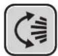
Adjusting the Airflow Direction

text_image
MASTER * 27.0°C A MON 15:30 Switch TimerYou can adjust the airflow direction to increase your comfort.
ATTENTION
• Always use a remote controller to adjust the angles of the flaps and louvres.
- If you attempt to move the flaps and louvres forcibly by hand when they are swinging, the mechanism may be damaged.
- Inside the air outlet, a fan is rotating at a high speed.
To start auto swing
Up and down airflow direction

Press

- “C” is displayed on the LCD.
- The flaps (horizontal blades) will begin to swing.

natural_image
Diagram showing a circular icon with rotation arrows and a server icon, no text or symbols presentRight and left airflow direction

Press

- “” is displayed on the LCD.
• The louvres (vertical blades) will begin to swing.
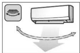
natural_image
Diagram showing airflow around a car with a curved arrow indicating direction (no text or symbols)The 3-D airflow direction

Press

- “ ⏻” and “ 📋” are displayed on the LCD.
• The flaps and louvres move in turn. - To cancel 3-D airflow, press either 📁 or again. The flaps or louvres will stop moving.

natural_image
Diagram showing airflow around a car air conditioner unit (no text or symbols)To set the flaps or louvres at the desired position
- This function is effective while the flaps or louvres are in auto swing mode.

sserP

whandthe flaps or louvres
reach the desired position.
• In the 3-D airflow, the flaps and louvres move in turn.
- “” or “” disappears from the LCD.

Adjusting the Airflow Rate
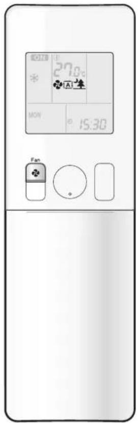
text_image
27:0 MON 15:30 FanYou can adjust the airflow rate to increase your comfort.
To adjust the airflow rate setting

• Each pressing of fan changes the airflow rate setting in sequence.
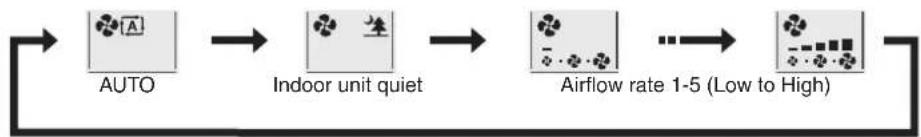
flowchart
graph LR
    A["AUTO"] --> B["Indoor unit quiet"]
    B --> C["Airflow rate 1-5 (Low to High)"]
- When the operation starts and noise from the indoor unit will become quieter.
- In the quiet operation mode, the airflow rate is set to a weak level.
| COOL and FAN operation DRY operation | |||||
 |  |  |  |  | The airflow rate setting cannot be changed. |
NOTE
Note on airflow direction setting
- The movable range of the flaps varies according to the operation mode.
Movable range of the flap

text_image
of the flap COOL / DRY FANNote on 3-D airflow
- Using 3-D airflow circulates cold air, which tends to collected at the bottom of the room, and hot air, which tends to collect near the ceiling, throughout the room, preventing areas of cold and hot developing.
Note on airflow rate setting
- At smaller airflow rates, the cooling effect is also smaller.

COMFORT AIRFLOW Operation

text_image
27:00 * MON 15:30 Comfort TimerCOMFORT AIRFLOW operation: The air direction and flow rate are adjusted so that the air will not blow directly at people in the room.
To start COMFORT AIRFLOW operation

• “ 🍼 is displayed on the LCD.
| COOL and DRY operation FAN operation | ||
| Flap direction | Goes up | Not available |
| Airflow rate | AUTO | |
To cancel COMFORT AIRFLOW operation
Press again.
• “ disappears from the LCD.
- The flap will return to the memory position from before COMFORT AIRFLOW operation.
Notes on "COMFORT AIRFLOW Operation"
• The flap position will change, preventing air from blowing directly on the occupants of the room.
- POWERFUL operation and COMFORT AIRFLOW operation cannot be used at the same time.
- The volume of air will be set to AUTO. If the upward and downward airflow direction is selected, the COMFORT AIRFLOW function will be canceled.
- Priority is given to the function of whichever button is pressed last.
- The COMFORT AIRFLOW function makes the following airflow direction adjustments. The flaps will move upward while cooling so that the airflow will be directed upward.

natural_image
Diagram of a airflow or ventilation system with a container mounted on a wall, showing airflow direction (no text or symbols)Cooling operation
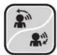
INTELLIGENT EYE Operation
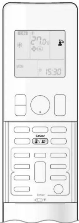
text_image
27.0°C MON 15:30 Sensor TimerThe INTELLIGENT EYE operation detects human movement and adjusts airflow direction. It can be set to avoid people or to direct airflow specifically at people. If no one is detected in the room for more than 20 minutes, the unit automatically enters energy saving operation.
CAUTION
- Do not place large objects near the INTELLIGENT EYE sensor. Also keep heating units and humidifiers outside the sensor's detection area. This sensor can detect undesirable objects.
- Do not hit or violently push the INTELLIGENT EYE sensor. This can lead to damage and malfunction.
To start INTELLIGENT EYE operation
DPress

and select the desired model.
• Each time is pressed, a different setting option is displayed on the LCD.
• The INTELLIGENT EYE lamp lights green.

text_image
Simple diagram with a person, clock, and sun icons, possibly representing a conceptual or educational concept.Display
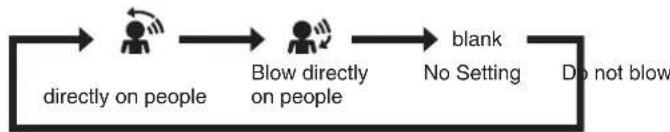
flowchart
graph LR
    A["Directly on people"] --> B["Blow directly on people"]
    B --> C["blank\nNo Setting"]
    C --> D["Do not blow"]
- When the flaps (horizontal blades) are swinging, selecting any of the modes above will cause the flaps (horizontal blades) to stop.
• The lamp lights when human movement is detected.
To cancel the INTELLIGENT EYE operation
Press

button.
• The INTELLIGEN EYE lamp goes off.
NOTE
• INTELLIGENT EYE operation is set to blow directly on people, the air conditioner tracks you horizontally, without the air blowing directly on you.
- When the INTELLIGENT EYE sensor detects the movement of people, it adjusts the airflow direction upward (while in COOL operation) adjusting the flaps. Depending on the settings, the louvres (vertical blades) will either direct airflow directly toward or away from people.

INTELLIGENT EYE Operation
How the INTELLIGENT EYE operation works
The INTELLIGENT EYE sensor detects human movement and adjusts the right and left direction. If no one is in the room for more than 20 minutes, the operation automatically changes to energy saving operation. The INTELLIGENT EYE sensor works differently depending on the situation.
[Example]
| A person is detected in area 1. | A person is detected in area 2. | People are detected in both areas. | No people are detected in the areas. | |
 | 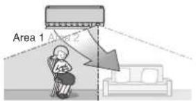 |  |  When the INTELLIGENT EYE operation and the COMFORT AIRFLOW operation are used together, the unit will not blow air directly at people (only in their general direction). When the INTELLIGENT EYE operation and the COMFORT AIRFLOW operation are used together, the unit will not blow air directly at people (only in their general direction). | 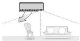 The air conditioner will switch to energy-saving mode after 20 minutes. The air conditioner will switch to energy-saving mode after 20 minutes. |
 |  |  |
* The airflow direction may differ from the illustrated direction depending on the actions and movements of the people in the areas.
INTELLIGENT EYE operation is useful for energy saving
Energy saving operation
- If no presence detected in the room for 20 minutes, energy saving operation starts automatically.
- This operation changes the temperature by -2^ in HEAT / +2^ in COOL / +2^ in DRY operation from the set temperature.
When the room temperature exceeds 30^ C, the operation changes the temperature by +1^ C in COOL / +1^ C in DRY operation from the set temperature. - This operation decreases the air intake slightly in FAN operation only.
NOTE
Notes on INTELLIGENT EYE operation
- Application range is as follows.
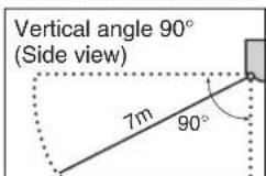
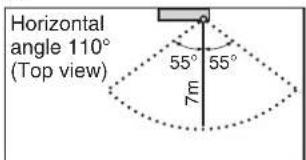
text_image
Horizontal angle 110° (Top view) 55° 55° 7m- While the air conditioner is in INTELLIGENT EYE operation, the louvres adjust the airflow direction if there are people in the sensing areas of the INTELLIGENT EYE so that the leftward or rightward air will not be directed to the people. If no people are detected in either area 1 or 2 for 20 minutes, the air conditioner switches to the energy-saving mode with the set temperature shifted by 2^ .
The air conditioner may switch to the energy-saving operation even if there are people in the areas.
This may occur depending on the clothes the people are wearing, if there is no movement of the people in the areas.
- The airflow direction from the louvres will be leftward if there are people in both areas 1 and 2. The air will also flow left if there is a person right in front of the sensor as the sensor judges that there are people in both areas.
- Due to the position of the sensor, people might be exposed to the airflow of the indoor unit if they are close to the front side of the indoor unit. If there are people close to the front side of the indoor unit or in both areas, it is recommended to use the COMFORT AIRFLOW and INTELLIGENT EYE operations simultaneously. Using both modes together, the air conditioner will not direct the airflow towards the people.
- The sensor may not detect moving objects further than 7m away. (Please see the application range.)
- Sensor detection sensitivity changes according to the indoor unit location, the speed of passers-by, temperature range, etc.
- The sensor could also mistakenly detect pets, sunlight, fluttering curtains and light reflected off of mirrors as passers-by.
- INTELLIGENT EYE operation will not switch on during POWERFUL operation.
- NIGHT SET mode ▶Page 21 will not switch on during use of INTELLIGENT EYE operation.

POWERFUL Operation
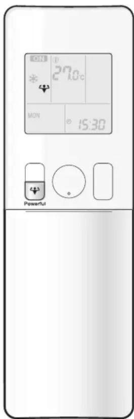
text_image
ON 27.0c MON 15:30 PowerfulPOWERFUL operation quickly maximizes the cooling effect in any operation mode. In this mode, the air conditioner operates at maximum capacity.
To start POWERFUL operation
Press during operation.
• “ Is displayed on the LCD.
- POWERFUL operation ends in 20 minutes. Then the system automatically operates again with the previous settings which were used before POWERFUL operation.
To cancel POWERFUL operation
Press again.
• “ disappears from the LCD.
NOTE
Notes on POWERFUL operation
- Pressing ⏻ causes the settings to be cancelled, and “💡” disappears from the LCD.
- POWERFUL operation will not increase the capacity of the air conditioner if the air conditioner is already in operation with its maximum capacity demonstrated.
- In COOL operation
To maximize the cooling effect, the capacity of outdoor unit increases and the airflow rate becomes fixed at the maximum setting. The temperature and airflow settings cannot be changed. - In DRY operation
The temperature setting is lowered by 2.5°C and the airflow rate is slightly increased. - In FAN operation
The airflow rate is fixed at the maximum setting.
Regarding the combination of POWERFUL and other operations
| POWERFUL + COMFORT AIRFLOW | Not available* |
| POWERFUL + ECONO | |
| POWERFUL + OUTDOOR UNIT QUIET |
*Priority is given to the function of whichever button is pressed last.
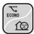
ECONO / OUTDOOR UNIT QUIET Operation

text_image
27.0°C MON 15:30 Ecoa/Outlet TimerECONO operation enables efficient operation by limiting the maximum power consumption.
This function is useful to prevent the circuit breaker from tripping when the unit operates alongside other appliances on the same circuit.
OUTDOOR UNIT QUIET operation lowers the noise level of the outdoor unit by changing the frequency and fan speed of the outdoor unit. This function is convenient during the night-time operation.
To start operation
Press Econo/Quiet and select the desired mode.
• Each time Ecano/Quiet We pressed, a different setting option is displayed on the LCD.

flowchart
graph LR
    A["ECONO OUTDOOR UNIT QUIET"] --> B["Combination"]
    B --> C["blank\nNo Setting"]
To cancel operation
Press Econo/Quiet until no icon is displayed.
NOTE
Notes on ECONO operation
- Pressing ⏻ causes the settings to be cancelled, and “ ” disappears from the LCD.
- If the power consumption level is already low, switching to ECONO operation will not reduce the power consumption.
Notes on OUTDOOR UNIT QUIET operation
• Even if the operation is stopped by using the remote controller or the indoor unit ON/OFF switch when using OUTDOOR UNIT QUIET operation,
"will remain lit on the remote controller display.
- OUTDOOR UNIT QUIET operation will not reduce the frequency nor fan speed if they already are operating at reduced levels.
- This operation is performed with lower power and therefore may not provide a sufficient cooling effect.
Possible combinations of ECONO / OUTDOOR UNIT QUIET operation and basic operations
| Operation mode | |||
| DRY COOL | FAN | ||
| ECONO | √ | √ | × |
| OUTDOOR UNIT QUIET | × | √ | × |

ON/OFF TIMER Operation

text_image
27.0°C ON 6:00 Select Cancel On TimerTimer functions are useful for automatically switching the air conditioner on or off at night or in the morning. You can also use the ON TIMER and OFF TIMER together.
To use ON TIMER with a 24 hour clock display (24 HOUR ON/OFF TIMER)
- Check that the clock is correct.
If not, set the clock to the present time. ▶ Page 10
• To set the ON TIMER in an hours remaining display. ▶ Page 10
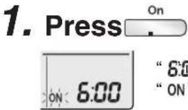
text_image
1. Press On ON 6:00 "8:00" "ON"- “①” and day of the week disappear from the LCD.
2. Press until the time setting reaches the point you like.
• Each pressing of either button increases or decreases the time setting by 10 minutes. Holding down either button changes the setting rapidly.
3. Press □ again.
- "ONand setting time are displayed on the LCD.
• The TIMER lamp lights orange.
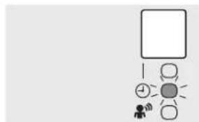
flowchart
graph TD
    A[" "] --> B[" "]
    B --> C[" "]
    C --> D[" "]
    D --> E[" "]
    E --> F[" "]
    F --> G[" "]
    G --> H[" "]
    H --> I[" "]
    I --> J[" "]
    J --> K[" "]
    K --> L[" "]
    L --> M[" "]
    M --> N[" "]
    N --> O[" "]
    O --> P[" "]
    P --> Q[" "]
    Q --> R[" "]
    R --> S[" "]
    S --> T[" "]
    T --> U[" "]
    U --> V[" "]
    V --> W[" "]
    W --> X[" "]
    X --> Y[" "]
    Y --> Z[" "]
Display
To cancel ON TIMER operation

- “ONand setting time disappear from the LCD.
- “💡” and day of the week are displayed on the LCD.
• The TIMER lamp goes off.
NOTE
Note on TIMER operation
- When TIMER is set, the present time is not displayed.
In the following cases, set the timer again.
• After the circuit breaker has turned off.
• After a power failure.
• After replacing the batteries in the remote controller.

ON/OFF TIMER Operation

text_image
27.0°C OFF 0:00 Off Select Cancel TimerTo use OFF TIMER with a 24 hour clock display (24 HOUR ON/OFF TIMER)
- Check that the clock is correct.
If not, set the clock to the present time. ▶ Page 10
• To set the ON TIMER in an hours remaining display. ▶ Page 10
1. Press Off

"0.08 displayed on the LCD.
"OFF" blinks.
- “ ⊕” and day of the week disappear from the LCD.
2. Press until the time setting reaches the point you like.
- Each pressing of either button increases or decreases the timem setting by 10 minutes. Holding down either button changes the time setting rapidly.
3. Press again.
- “OFF and setting time are displayed on the LCD.
• The TIMER lamp lights orange.

flowchart
graph TD
    A[" "] --> B[" "]
    B --> C[" "]
    C --> D[" "]
    D --> E[" "]
    E --> F[" "]
    F --> G[" "]
    G --> H[" "]
    H --> I[" "]
    I --> J[" "]
    J --> K[" "]
    K --> L[" "]
    L --> M[" "]
    M --> N[" "]
    N --> O[" "]
    O --> P[" "]
    P --> Q[" "]
    Q --> R[" "]
    R --> S[" "]
    S --> T[" "]
    T --> U[" "]
    U --> V[" "]
    V --> W[" "]
    W --> X[" "]
    X --> Y[" "]
    Y --> Z[" "]
Display
To cancel OFF TIMER operation
Press Cancel
- “OFF and setting time disappear from the LCD.
- “ ⊕” and day of the week are displayed on the LCD.
• The TIMER lamp goes off.
To combine ON TIMER and OFF TIMER
- A sample setting for combining the 2 timers is shown below.

text_image
(Example) Present time: 23:00 (The unit operating) OFF TIMER at 0:00 ON TIMER at 14:00) Combined OFF 0:00 ON 14:00NOTE
NIGHT SET mode
- When the OFF TIMER is set, the air conditioner automatically adjusts the temperature setting (0.5°C up in COOL) to prevent excessive cooling during sleeping hours.

text_image
27.8°C ON ihr Select On Off Cancel TimerTo use the ON/OFF TIMER with an hours remaining display (COUNT UP-DOWN ON/OFF TIMER)
- Check that the clock is correct.
If not, set the clock to the present time. ▶ Page 10
1. Press and hold on or for about 5 seconds, when signal indicator (▲) blink, release your finger from the button.

For ON TIMER
"Ibr" is displayed on the LCD.
"ON" blinks.
For OFF TIMER
"Ibr" is displayed on the LCD.
"OFF" blinks.
- “ ⏻ ” and day of the week disappear from the LCD.
2. Press until the time setting reaches the point you like.
• Each pressing of the button increases or decreases the time setting by 1 hour.
• The time can be set between 1 and 12 hours.
3. Press on or again.
- “ON” or “OFF”, and setting time are displayed on the LCD.
• The TIMER lamp lights orange.

Display
- To change the display mode from COUNT UP-DOWN ON/OFF TIMER to 24 HOUR ON/OFF TIMER, repeat STEP 1, and continue from STEP 2 of "24 HOUR ON/OFF TIMER". ▶ Page 20.21
- Timer display mode cannot be changed while "ON" or "OFF" are blinking. Press ☐ or ☐ to stop the blinking.
Combining display modes
- Different display modes (24 HOUR ON/OFF TIMER and COUNT UP-DOWN ON/OFF TIMER) can be used for the ON TIMER and OFF TIMER simultaneously.
(Example)-
Present time: 22:00 [unit is in operation] OFF TIMER at 1:00 (3 hours after present time) ON TIMER at 6:00 (8 hours after present time) Combined

text_image
OFF 3hr ON 6:00 OFF 1:00 ON 8hr OFF 3hr ON 8hrNOTE
Notes on COUNT UP-DOWN ON/OFF TIMER
- After setting, the time displayed on the LCD will automatically count down by 1 hour for every 1 hour that passes. For example, if the OFF TIMER is set to 3 hours, the display will change as follows: 3hr 2hr 1hr blank (OFF)
Switching between ON/OFF TIMER display modes (24 hour clock and hours remaining display)
- When change display mode (from 24 HOUR ON/OFF TIMER to COUNT UP-DOWN ON/OFF TIMER or from COUNT UP-DOWN ON/OFF TIMER to 24 HOUR ON/OFF TIMER), cancel timer. So, to use timer, set timer again.

WEEKLY TIMER Operation
Up to 4 timer settings can be saved for each day of the week. This is convenient to adapt the WEEKLY TIMER to your family's life style.
Setting example of the WEEKLY TIMER
The same timer settings are used from Monday through Friday, while different timer settings are used for the weekend.
| [Monday] | Make timer settings for programmes 1-4. ▶Page 24Programme 1 Programme 2 Programme 3 Programme 4  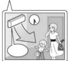 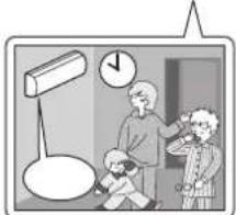 |
| [Tuesday] to [Friday] | Use the copy mode to make settings for Tuesday to Friday, because these settings are the same as those for Monday. ▶Page 26Programme 1 Programme 2 Programme 3 Programme 4 |
| [Saturday] | No timer settings |
| [Sunday] | Make timer settings for programmes 1-4. ▶Page 24Programme 1 Programme 2 Programme 3 Programme 4 |
- Up to 4 reservations per day and 28 reservations per week can be set using the WEEKLY TIMER. The effective use of the copy mode simplifies timer programming.
- The use of ON-ON-ON-ON settings, for example, makes it possible to schedule operating mode and set temperature changes. Furthermore, by using OFF-OFF-OFF-OFF settings, only the turn off time of each day can be set. This will turn off the air conditioner automatically if you forget to turn it off.
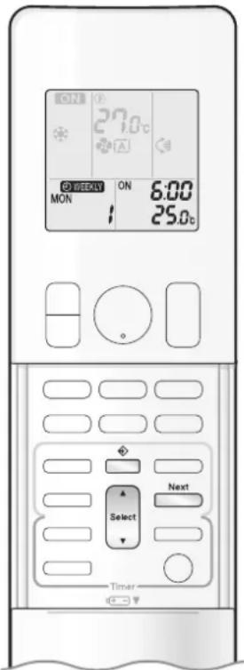
text_image
ON 27.0°C OFF MON ON 6:00 25.0°C Select Next TimerTo use WEEKLY TIMER operation
Setting mode
- Make sure the day of the week and time are set. If not, set the day of the week and time. ▶ Page 10
Programme 1 Programme 2 Programme 3 Programme 4
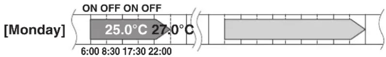
text_image
[Monday] ON OFF ON OFF 25.0°C 27.0°C 6:00 8:30 17:30 22:00Setting Displays

flowchart
graph LR
    A["MON"] --> B["ON/OFF"]
    B --> C["ON/OFF 6:00"]
    C --> D["Temperature 25.0s"]
1. Press
- The day of the week and the reservation number of the current day will be displayed.
- 1 to 4 settings can be made per day.
2. Press Select to select the desired day of the week and reservation number.
- Pressing ▲ changes the reservation number and the day of the week.
3. Press Next .
- The day of the week and reservation number will be set.
- “ WEEKLY ” and “ ON ” blink.
4. Press Select to select the desired mode.
- Pressing Select changes the "ON" or "OFF" setting in sequence.

flowchart
graph LR
    A["ON"] --> B["OFF"]
    B --> C["blank"]
    D["ON TIMER"] --> A
    E["OFF TIMER"] --> B
    F["No Setting"] --> C
- In case the reservation has already been set, selecting “blank” deletes the reservation.
- Proceed to STEP 9 if "blank" is selected.
- To return to the day of the week and reservation number setting, press Back.
5. Press Next .
- The ON/OFF TIMER mode will be set.
- “WEEKLY” and the time blink.

WEEKLY TIMER Operation

text_image
27.0°C ON TUE 6:00 25.0°C Back Select Next Timer6. Press to select the desired time.
- The time can be set between 0:00 and 23:50 in 10-minute intervals.
- To return to the ON/OFF TIMER mode setting, press □ Back
• Proceed to STEP 9 when setting the OFF TIMER.
7. Press Next
• The time will be set.
• “ ⏻ WEEKLY ” and the temperature blink.
8. Press to select the desired temperature.
• The temperature can be set between 10.0^ C and 32.0^ C.
COOL or AUTO: The unit operates at 18.0^ C even if it is set to 10.0^ C. to 17.0^ C. ▶ Page 12
HEAT or AUTO : The unit operates at 30.0^ C even if it is set to 31.0^ C to 32.0^ C. ▶ Page 12
• To return to the time setting, press Back.
- The set temperature is only displayed when the mode setting is on.
9. Press Next .
- The temperature will be set and go to the next reservation setting.
- The temperature is set while in ON TIMER operation, and the time is set while in OFF TIMER operation.
• The next reservation screen will appear.
• To continue further settings, repeat the procedure from STEP 4.
10. Press to complete the setting.
- Be sure to direct the remote controller toward the indoor unit and check for a receiving tone and blinking of the OPERATION lamp.
- “WEEKLY” is displayed on the LCD and WEEKLY TIMER operation is activated.
• The TIMER lamp lights orange.

text_image
Simple diagram with a rectangle, a sun, and icons including a person, a clock, and a sunburst symbol.Display
- A reservation made once can be easily copied and the same settings used for another day of the week. Refer to Copy mode ▶ Page 26
NOTE
Notes on WEEKLY TIMER operation
- Do not forget to set the clock on the remote controller first. ▶ Page 10
- The day of the week, ON/OFF TIMER mode, time and set temperature (only for ON TIMER mode) can be set with the WEEKLY TIMER. Other settings for the ON TIMER are based on the settings just before the operation.
- WEEKLY TIMER and ON/OFF TIMER operation cannot be used at the same time. The ON/OFF TIMER operation has priority if it is set while WEEKLY TIMER is still active. The WEEKLY TIMER will enter the standby state, and “WEEKLY” will disappear from the LCD. When the ON/OFF TIMER is up, the WEEKLY TIMER will automatically become active.
- Only the time and set temperature with the WEEKLY TIMER are sent with the ☐. Set the WEEKLY TIMER only after setting the operation mode, the airflow rate and the airflow direction ahead of time.
- Turning off the circuit breaker, power failure, and other similar events will render operation of the indoor unit's internal clock inaccurate. Reset the clock. ▶Page 10
- Back can be used only for the time and temperature settings. It cannot be used to go back to the reservation number.
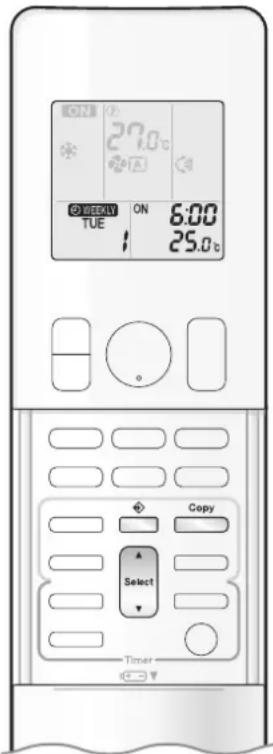
text_image
ON 27.0°C OFF CIVY TUE ON 6:00 25.0°C Copy Select TimerCopy mode
- A reservation made once can be copied to another day of the week. The whole reservation of the selected day of the week will be copied.

text_image
Programme 1 Programme 2 Programme 3 Programme 4 ON OFF ON OFF [Monday] 25.0°C 27.0°C 6:00 8:30 17:30 22:00 COPY
line
| Time Period | Temperature Range | | ----------------- | ----------------- | | 6:00 - 8:30 | 25.0°C | | 17:30 - 22:00 | 27.0°C |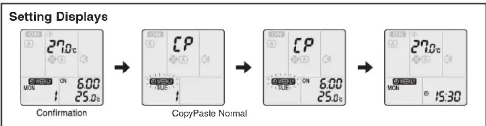
flowchart
graph LR
    A["ON 27.0°C<br>A<br>WEEKLY ON 6:00<br>MON 25.0°C"] --> B["ON CP<br>A<br>WEEKLY TUE"]
    B --> C["ON CP<br>A<br>WEEKLY TUE ON 6:00<br>25.0°C"]
    C --> D["ON 27.0°C<br>A<br>WEEKLY MON 15:30"]
- Press
- Press Select to confirm the day of the week to be copied.
- Press Copy
- The whole reservation of the selected day of the week will be copied.
- Press Select to select the destination day of the week.
-
Press Copy
-
The reservation will be copied to the selected day of the week. The whole reservation of the selected day of the week will be copied.
-
To continue copying the settings to other days of the week, repeat STEP 4 and STEP 5.
-
Press ☐ to complete the setting.
- “WEEKLY” is displayed on the LCD and WEEKLY TIMER operation is activated.
NOTE
Note on COPY MODE
- The entire reservation of the source day of the week is copied in the copy mode.
In the case of making a reservation change for any day of the week individually after copying the content of weekly reservations, press and change the settings in the steps of Setting mode. ▶ Page 24

WEEKLY TIMER Operation

text_image
ON 27.0°C ON TUE 6:00 25.0°C Weekly Select Next TimerConfirming a reservation
• The reservation can be confirmed.

text_image
Setting Displays TUE 15:30 Normal ON 6:00 TUE 25.0c Confirmation1. Press
- The day of the week and the reservation number of the current day will be displayed.
2. Press to select the day of the week and the reservation number to be confirmed.
- Pressing Select displays the reservation details.
- To change the confirmed reserved settings, select the reservation number and press Next. The mode is switched to setting mode. Proceed to Setting mode STEP 4. ▶ Page 24
3. Press to exit the confirmation mode.
- “WEEKLY” is displayed on the LCD and WEEKLY TIMER operation is activated.
• The TIMER lamp lights orange.

flowchart
graph TD
    A["Start"] --> B{Decision}
    B -->|Yes| C["User Icon"]
    B -->|No| D["Process Step"]
    D --> E["End"]
Display
To deactivate WEEKLY TIMER operation

Weekly sser while “ ⚙ WEEKLY ” is displayed on the LCD.
- “ Ⓧ WEEKLY ” disappears from the LCD.
• The TIMER lamp goes off.
• To reactivate the WEEKLY TIMER operation, press □ again. - If a reservation deactivated with ____ is activated once again, the last reservation mode will be used.
NOTE
- If not all the reservation settings are reflected, deactivate the WEEKLY TIMER operation once. Then press ☐ again to reactivate the WEEKLY TIMER operation.
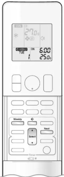
text_image
ON 27.0°C A OFF/WHM ON 6:00 TUE 25.0°C Weekly Next Select TimerTo delete reservations
An individual reservation
1. Press
- The day of the week and the reservation number will be displayed.
2. Press to select the day of the week and the reservation number to be deleted.
3. Press Next
- “ WEEKLY ” and “ ON ” or “ OFF ” blink.
4. Press until no icon is displayed.
- Pressing changes the ON/OFF TIMER mode in sequence.
- Selecting "blank" will cancel any reservation you may have.

flowchart
graph LR
    A["ON"] --> B["OFF"]
    B --> C["blank"]
    D["ON TIMEROFF TIMER"] --> E["No Setting"]
5. Press Next .
- The selected reservation will be deleted.
6. Press
- If there are still other reservations, WEEKLY TIMER operation will be activated.
Reservations for each day of the week
- This function can be used for deleting reservations for each day of the week.
- It can be used while confirming or setting reservations.
1. Press Select to select the day of the week to be deleted.
2. Hold for about 5 seconds.
- The reservation of the selected day of the week will be deleted.
All reservations
Hold Weekly for about 5 seconds with the normal display.
- Be sure to direct the remote controller toward the indoor unit and check for a receiving tone.
- This operation cannot be used for the WEEKLY TIMER setting display.
- All reservations will be deleted.
Care and Cleaning

CAUTION
- Before cleaning, be sure to stop the operation and turn off the circuit breaker.
- Do not touch the aluminum fins of the indoor unit. If you touch those parts, this may cause an injury.
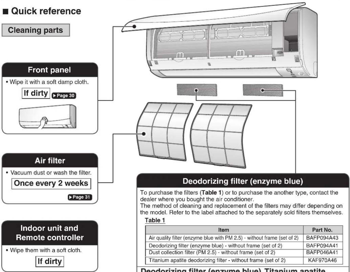
text_image
■ Quick reference Cleaning parts Front panel • Wipe it with a soft damp cloth. If dirty ▶ Page 30 Air filter • Vacuum dust or wash the filter. Once every 2 weeks ▶ Page 31 Indoor unit and Remote controller • Wipe them with a soft cloth. If dirty Deodorizing filter (enzyme blue) To purchase the filters (Table 1) or to purchase the another type, contact the dealer where you bought the air conditioner. The method of cleaning and replacement of the filters may differ depending on the model. Refer to the label attached to the separately sold filters themselves. Table 1 Item Part No. Air quality filter (enzyme blue with PM 2.5) - without frame (set of 2) BAFP094A43 Deodorizing filter (enzyme blue) - without frame (set of 2) BAFP094A41 Dust collection filter (PM 2.5) - without frame (set of 2) BAFP046A41 Titanium apatite deodorizing filter - without frame (set of 2) KAF970A46 Deodorizing filter (enzyme blue).Titanium apatiteDeodorizing filter (enzyme blue), Titanium apatite deodorizing filter.
• Vacuum dust or replace the filter. [Cleaning] [Replacement]
Once every 6 months
Once every 3 years
▶ Page 32
Air quality filter (enzyme blue with PM 2.5), Dust collection filter (PM 2.5)
- No cleaning is required. Please replace the filter every 6 months. ▶ Page 28
NOTE
For cleaning, do not use any of the following:
• Water hotter than 40.0°C
• Volatile liquid such as benzene, petrol and thinner
- Polishing compounds
- Rough materials such as a scrubbing brush

natural_image
Illustration of a kettle, a brush, and a bottle (no text or symbols)
CAUTION
- When removing or attaching the front panel, stand on a solid, stable base and take care not to fall.
- When removing or attaching the front panel, support the panel securely with your hand to prevent it from falling.
■ Front panel
1. Open the front panel.
- Hold the front panel by the panel tabs on the 2 sides and open it.

text_image
Panel tab2. Remove the front panel.
- Slide the front panel to either the left or right and pull it toward you. This will disconnect the front panel shaft on one side.
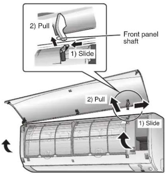
text_image
2) Pull 1) Slide Front panel shaft 2) Pull 1) Slide- Disconnect the front panel shaft on the other side in the same manner.
3. Clean the front panel.
- Wipe it with a soft damp cloth.
- Only neutral detergent may be used.
- In case of washing the panel with water, wipe it with a dry soft cloth, and let it dry in the shade after washing.
4. Attach the front panel.
- Align the front panel shaft on the left and right of the front panel with the grooves, then push them all the way in.
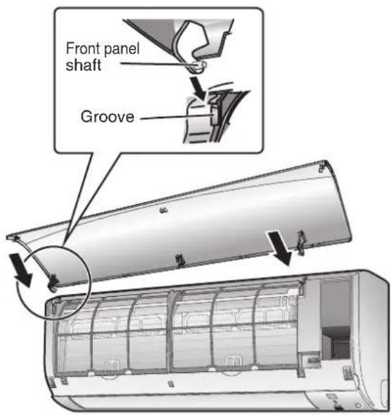
text_image
Front panel shaft Groove5. Close the front panel slowly.
- Press the front panel at both sides and thecentre.
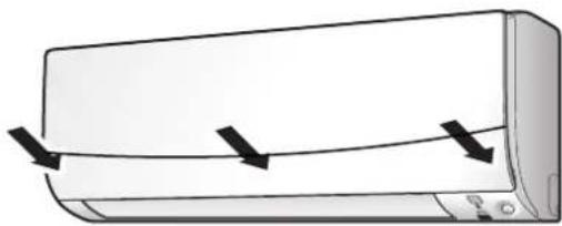
natural_image
Illustration of a wall-mounted air conditioner unit with three black arrows indicating airflow direction (no text or symbols)- Make sure that the front panel is securely fixed.
Care and Cleaning
■ Air filter
1. Open the front panel. ▶ Page 30
2. Pull out the air filters.
- Push the filter tab at the centre of each air filter a little upwards, then pull it down.
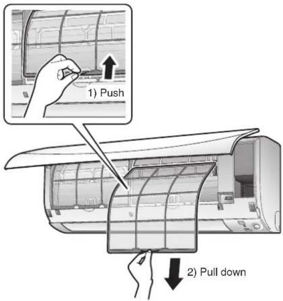
text_image
1) Push 2) Pull down3. Wash the air filters with water or clean them with a vacuum cleaner.
- It is recommended to clean the air filters every 2 weeks.
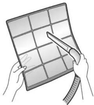
natural_image
Illustration of hands holding a grid-based panel with scissors, no text or symbols presentIf the dust does not come off easily
- Wash the air filters with neutral detergent thinned with lukewarm water, then let them dry in the shade.
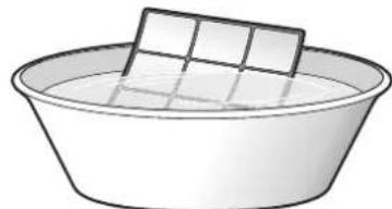
natural_image
Simple line drawing of a basin with a rectangular object on top (no text or symbols)- Set the filters as they were.
- Close the front panel slowly.
■ Filter (small)
* For the applicable filter type, please refer to ▶ Page 30.
Attaching
-
Open the front panel and pull out the air filters. ▶ Page 31
-
Insert the filter.
- Check that the filters are inserted securely under the tabs.
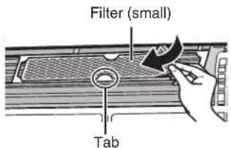
text_image
Filter (small) TabCleaning and Replacement
-
Open the front panel and pull out the air filters. ▶ Page 31
-
Take off the filter.
- Remove the filters from the tabs.

text_image
Filter (small) TabNOTE
• Operation with dirty filters:
- cannot deodorise the air,
- cannot clean the air,
– results in poor cooling,
-may cause odour.
- Dispose of old filters as non-flammable waste.
- Clean or replace.
[Cleaning]
Deodorizing filter (enzyme blue) : Blue / Titanium apatite deodorizing filter : Blue-Black
3-1 Vacuum dust, and soak in lukewarm water or water for about 10 to 15 minutes if very dirty.
3-2 After washing, shake off remaining water and let them dry in the shade.
- This filter can be renewed by washing it with water once every 6 months and we recommend replacing it once every 3 years.
- Do not wiring out the filter when removing water from it.
Air quality filter (enzyme blue with PM 2.5) : Blue-White / Dust collection filter (PM 2.5) : White
- Do not wash the filters as this will reduce their efficiency.
- It is recommended to replace it once every 6 months.
[Replacement]
Remove each filter from the filter frame and prepare a new one.
- When attaching the filter, check that the filter is properly set in the tabs.
- Set the filters as they were and close the front panel.
- Press the front panel at both sides and the center.
Care and Cleaning
■ Prior to a long period of non-use
1. Operate the FAN mode for several hours on a fine day to dry out the inside.
- Press Mode and select "♣".
- Press On/Off and start the operation.
2. After operation stops, turn off the circuit breaker for the room air conditioner.
3. Take out the batteries from the remote controller.
■ We recommend periodical maintenance
- In certain operating conditions, the inside of the air conditioner may get foul after several seasons of use, resulting in poor performance. It is recommended to have periodical maintenance by a specialist in addition to regular cleaning by the user.
- For specialist maintenance, please contact the dealer where you bought the air conditioner.
- The maintenance cost must be borne by the user.
FAQ
Indoor unit
The flaps do not start swinging immediately.
- The air conditioner is adjusting the position of the laps. The flaps start moving soon.
Operation does not start soon.
■ When was pressed soon after operation was stopped.
■ When the mode was reselected.
• This is to protect the air conditioner. You should wait for about 3 minutes.
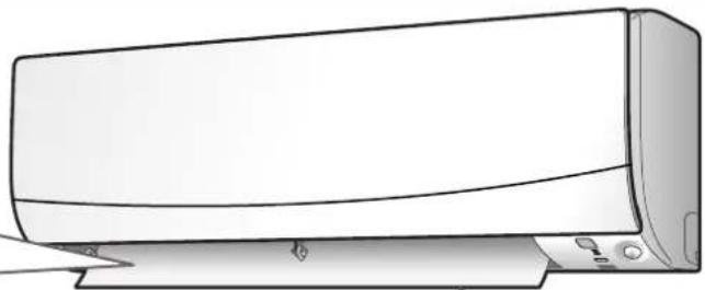
natural_image
Line drawing of a wall-mounted air conditioner unit (no text or symbols)Different sounds are heard.
■ A sound like flowing water
- This sound is generated because the refrigerant in the air conditioner is flowing.
- This is a pumping sound of the water in the air conditioner and can be heard when the water is pumped out from the air conditioner during COOL or DRY operation.
- The refrigerant flows in the air conditioner even if the air conditioner is not working when the indoor units in other rooms are in operation.
■ Blowing sound
- This sound is generated when the flows of the refrigerant in the air conditioner is switched over.
■ Ticking sound
- This sound is generated when the cabinet and frame of the air conditioner slightly expand or shrink as a result of temperature changes.
■ Whistling sound
- This sound is generated when refrigerant flows during defrosting operation.
■ Clicking sound during operation or idle time
- This sound is generated when the refrigerant control valves or the electrical parts operate.
■ Clopping sound
- This sound is heard from the inside of the air conditioner when the exhaust fan is activated while the room doors are closed. Open the window or turn off the exhaust fan.
■ Rotating machinery causes sound
- Sound is heard when the vertical swing flaps and the horizontal swing flaps move.
- When the air conditioner is operating in a quiet environment and the airflow rate of the indoor unit is set to Quiet Mode or Low Mode, the motion of the swing flaps may cause sound.
Outdoor unit
The outdoor unit emits water.
In COOL or DRY operation
- Moisture in the air condenses into water on the cool surface of the outdoor unit piping and drips.

natural_image
Line drawing of a large air conditioning unit with a circular vent grille and mounting base (no text or symbols)*The appearance of the outdoor unit may differ from some models.
Troubleshooting
Before making an inquiry or a request for repair, please check the following.
If the problem persists, consult your dealer.

Not trouble
These cases are not troubles.

Check
Please check again before requesting repairs.
The air conditioner does not operate
| Case Description / what to check | |
| OPERATION lamp is off. | Has the circuit breaker been tripped or the fuse blown?Is there a power failure?Are batteries set in the remote controller? |
| OPERATION lamp is blinking. | Turn off the power with the circuit breaker and restart operation with the remote controller.If the OPERATION lamp is still blinking, check the error code and consult your dealer. |
The air conditioner suddenly stops operating
| Case Description / what to check | |
| OPERATION lamp is on. | To protect the system, the air conditioner may stop operating after sudden large voltage fluctuations. It automatically resumes operation in about 3 minutes. |
| OPERATION lamp is blinking. | Is there anything blocking the air inlet or air outlet of the indoor unit or outdoor unit? Stop operation and after turning off the circuit breaker, remove the obstruction. Then restart operation with the remote controller. If the OPERATION lamp is still blinking, check the error code and consult your dealer. ▶ Page 38 |
The air conditioner does not stop operating
| Case Description / what to check | |
| The air conditioner continues operating even after operation is stopped. | ☑ Immediately after the air conditioner is stopped• The outdoor unit fan continues rotating for about another 1 minute to protect the system.• While the air conditioner is not in operation• When the outdoor temperature is high, the outdoor unit fan may start rotating to protect the syste. |
The room does not cool down
| Case Description / what to check | |
| Air does not come out. | When the air conditioner operates immediately after the circuit breaker is turned onThe air conditioner is preparing to operate. Wait for about 3 to 15 minutes. |
| Air does not come out / Air comes out. | Is the airflow rate setting appropriate?Is the airflow rate setting low, such as “Indoor unit quiet” or “1”? Increase the airflow rate setting.Is the set temperature appropriate?Is the adjustment of the airflow direction appropriate? |
| Air comes out. | Is there any furniture directly under or beside the indoor unit?Is the air conditioner in ECONO operation or OUTDOOR UNIT QUIET operation?Are the air filters dirty?Is there anything blocking the air inlet or air outlet of the indoor unit or outdoor unit?Is a window or door open?Is an exhaust fan turning? |
Mist comes out
| Case Description / what to check | |
| Mist comes out of the indoor unit. | This happens when the air in the room is cooled into mist by the cold airflow during COOL or other operation. |
Remote controller
| Case Description / what to check | |
| The unit does not receive signals from the remote controller or has a limited operating range. | The batteries may be exhausted.Replace both batteries with new dry batteries AAA.LR03 (alkaline).For details, refer to “Preparation Before Operation”. ▶Page 9Signal communication may be disabled if an electronic-starter-type fluorescent lamp (such as inverter-type lamps) is in the room. Consult your dealer if that is the case.The remote controller may not function correctly if the transmitter is exposed to direct sunlight. |
| LCD is faint, is not working, or the display is erratic. | The batteries may be exhausted.Replace both batteries with new dry batteries AAA.LR03 (alkaline).For details, refer to “Preparation Before Operation”. ▶Page 9 |
| Other electric devices start operating. | If the remote controller activates other electric devices, move them away or consult your dealer. |
Air has an odour
| Case Description / what to check | |
| The air conditioner gives off an odour. | The room odour absorbed in the unit is discharged with the airflow.We recommend you to have the indoor unit cleaned. Please consult your dealer. |
Others
| Case Description / what to check | |
| The air conditioner suddenly starts behaving strangely during operation. | The air conditioner may malfunction due to lightning or radio.If the air conditioner malfunctions, turn off the power with the circuit breaker and restart the operation with the remote controller. |
| The ON/OFF TIMER does not operate according to the settings. | Check if the ON/OFF TIMER and the WEEKLY TIMER are set to the same time.Change or deactivate the settings in the WEEKLY TIMER. ▶Page 23 |
Notes on the operating conditions
- If operation continues under any conditions other than those listed in the table,
- A safety device may activate to stop the operation.
- Dew may form on the indoor unit and drip from it when COOL or DRY operation is selected.
| Mode | Operating conditions |
| DRY | Outdoor temperature : -10.0-46.0°CIndoor temperature : 18.0-32.0°CIndoor humidity : 80% max. |
| COOL | Outdoor temperature : -10.0-46.0°CIndoor temperature : 18.0-32.0°CIndoor humidity : 80% max. |
Troubleshooting
■ Call your dealer immediately

WARNING
When an abnormality (such as a burning smell) occurs, stop operation and turn off the circuit breaker.
- Continued operation in an abnormal condition may result in troubles, electric shocks or fire.
- Consult the dealer where you bought the air conditioner.
Do not attempt to repair or modify the air conditioner by yourself.
- Incorrect work may result in electric shocks or fire.
- Consult the dealer where you bought the air conditioner.
If one of the following symptoms takes place, call your dealer immediately.
- The power cord is abnormally hot or damaged.
- An abnormal sound is heard during operation.
- The circuit breaker, a fuse, or the earth leakage circuit breaker cuts off the operation frequently.
- A switch or a button often fails to work properly.
• There is a burning smell.
• Water leaks from the indoor unit.
Turn off the circuit breaker and call your dealer.

■ After a power failure
- The air conditioner automatically resumes operation in about 3 minutes. You should just wait for a while.
Lightning
- If there is a risk lightning could strike in the neighbourhood, stop operation and turn off the circuit breaker to protect the system.
■ Disposal requirements
- Dismantling of the unit, handling of the refrigerant, oil and other parts, should be done in accordance with the relevant local and national regulations.

text_image
ON 88 STD ON OFF ON MONTLEWED THUFRI SATSUN ON OFF ON 38:88 Cancel Timer■ Fault diagnosis by remote controller
- The remote controller can receive relevant error codes from the indoor unit.
-
When is held down for about 5 seconds, "00 blinks in the temperature display section.
-
Press repeatedly until a continuous beep is produced.
- The code indication changes as shown below, and notifies you with a long beep.
| CODE MEANING | ||
| SYSTEM | 00NORMAL | |
| UAINDOOR | OUTDOOR UNIT COMBINATION FAULT | |
| U0REFRIGERANT SHORTAGE | ||
| U2DROP VOLTAGE OR MAIN CIRCUIT OVERVOLTAGE | ||
| U4FAILURE OF TRANSMISSION (BETWEEN INDOOR UNIT AND OUTDOOR UNIT) | ||
| INDOOR UNIT | A1INDOOR | PCB DEFECTIVENESS |
| A5 | HIGH PRESSURE CONTROL OR FREEZE-UP PROTECTOR | |
| A6FAN MOTOR FAULT | ||
| C4 | FAULTY HEAT EXCHANGER TEMPERATURE SENSOR | |
| C9 | FAULTY SUCTION AIR TEMPERATURE SENSOR | |
| OUTDOOR UNIT | EACOOLING-HEATING SWITCHING ERROR | |
| E1CIRCUIT BOARD FAULT | ||
| E5OL STARTED | ||
| E6FAULTY | COMPRESSOR START UP | |
| E7 | DC FAN MOTOR FAULT | |
| E8OVERCURRENT INPUT | ||
| F3 | HIGH TEMPERATURE DISCHARGE PIPE CONTROL | |
| F6HIGH PRESSURE CONTROL (IN COOLING) | ||
| H0 SENSOR FAULT | ||
| H6 | OPERATION HALT DUE TO FAULTY POSITION DETECTION SENSOR | |
| H8 DC CURRENT SENSOR FAULT | ||
| H9 | FAULTY SUCTION AIR TEMPERATURE SENSOR | |
| J3 | FAULTY DISCHARGE PIPE TEMPERATURE SENSOR | |
| J6 | FAULTY HEAT EXCHANGER TEMPERATURE SENSOR | |
| L3 | ELECTRICAL PARTS HEAT FAULT | |
| L4 | HIGH TEMPERATURE AT INVERTER CIRCUIT HEATSINK | |
| L5OUTPUT OVERCURRENT | ||
| P4 | FAULTY INVERTER CIRCUIT HEATSINK TEMPERATURE SENSOR | |
NOTE
- A short beep and 2 consecutive beeps indicate non-corresponding codes.
- To cancel the code display, hold □ down for about 5 seconds. The code display also clears if no button is pressed for 1 minute.
Quick Reference

flowchart
graph TD
    A["Air Condition"] --> B["On/Off Fan"]
    B --> C{Temperature Control}
    C --> D["Mode: 27.0°C"]
    C --> E["Switch: 15:30"]
    D --> F["ON: 18°C → 32°C"]
    E --> G["Mode: 18°C → 32°C"]
    F --> H["Weather Change Icon"]
    G --> I["Weather Change Icon"]
    H --> J["Refrigeration Mode"]
    I --> K["Refrigeration Mode"]
    J --> L["Refrigeration Mode"]
    K --> M["Refrigeration Mode"]
    L --> N["Refrigeration Mode"]
    M --> O["Refrigeration Mode"]
    N --> P["Refrigeration Mode"]
    O --> Q["Refrigeration Mode"]
    P --> R["Refrigeration Mode"]
    Q --> S["Refrigeration Mode"]
    R --> T["Refrigeration Mode"]
    S --> U["Refrigeration Mode"]
    T --> V["Refrigeration Mode"]
    U --> W["Refrigeration Mode"]
    V --> X["Refrigeration Mode"]
    W --> Y["Refrigeration Mode"]
    X --> Z["Refrigeration Mode"]
DAIKIN INDUSTRIES, LTD.
Head office:
Umeda Center Bldg., 2-4-12, Nakazaki-Nishi,
Kita-ku, Osaka, 530-8323 Japan
Tokyo office:
JR Shinagawa East Bldg., 2-18-1, Konan,
Minato-ku, Tokyo, 108-0075 Japan
https://www.daikin.com

The two-dimensional bar code is a manufacturing code.
OPERATION MANUAL
DAIKIN ROOM AIR CONDITIONER

natural_image
Line drawing of a rectangular air conditioner unit with ventilation grilles and control buttons (no text or symbols)MODELS
FTKM50Q2VMA
FTKM60Q2VMA
FTKM71Q2VMA

natural_image
Illustration of a globe with stylized buildings and continents, no text or symbols presentFeatures
Enhanced comfort and energy savings
INTELLIGENT EYE
The INTELLIGENT EYE sensor detects human movement in a room for more than 20 minutes, the operation automatically changes to energy saving operation. ▶ Page 16

WEEKLY TIMER
Up to 4 timer settings can be saved for each day of the week according to your family's life style. The WEEKLY TIMER allows you to set on/off times and the desired temperature. ▶ Page 23
Other functions

COMFORT AIRFLOW OUTDOOR UNIT QUIET
The airflow direction is upward while in COOL operation, and downward while in HEAT operation. This function prevents cold or warm air from blowing directly on your body. ▶ Page 15

OUTDOOR UNIT QUIET operation assures a low noise level of the outdoor unit. This function is useful to maintain a quiet neighbourhood.
Page 19

text_image
ECONO ECONO This function enables efficient operation by limiting the maximum power consumption. It is useful when using the air conditioner and other electrical devices simultaneously on a shared electrical circuit. Page 19Contents
Read Before Operation
Safety Precautions 3
Names of Parts 5
Preparation Before Operation 9
Basic Operation

DRY · COOL · FAN Operation...... 11

Adjusting the Airflow Direction...... 13

Adjusting the Airflow Rate...... 14
Useful Functions

COMFORT AIRFLOW Operation.....15

INTELLIGENT EYE Operation...... 16

POWERFUL Operation.... 18

ECONO/OUTDOOR UNIT QUIET Operation.... 19
TIMER Operation

ON/OFF TIMER Operation...... 20

WEEKLY TIMER Operation......23
Care
Care and Cleaning 29
■ When the Need Arises
FAQ 34
Troubleshooting 35
Safety Precautions

Read the precautions in this manual carefully before operating the unit.

This appliance is filled with R32.
- Keep this manual where the user can easily find it.
- The precautions described herein are classified as WARNING and CAUTION. They both contain important information regarding safety. Be sure to observe all precautions without fail.

WARNING
Failure to follow these instructions properly may result in personal injury or loss of life.

CAUTION
Failure to follow these instructions properly may result in property damage or personal injury, which may be serious depending on the circumstances.

Never attempt.

Be sure to follow the instructions.

Be sure to establish an earth connection.

Never touch the air conditioner nor the remote controller with wet hands.

Never wet the air conditioner nor the remote controller
• After reading, keep this manual in a convenient place so that you can refer to it whenever necessary. If the equipment is transferred to a new user, be sure also to hand over the manual.

WARNING

- Do not use means to accelerate the defrosting process or to clean, other than those recommended by the manufacturer.
- The appliance must be stored in a room without continuously operating ignition sources (for example: open flames, an operating gas appliance or an operating electric heater).
- Do not pierce or burn.
- Be aware that refrigerants may not contain an odour.
- The appliance must be installed, operated and stored in a room with a floor area larger than 4.6m^2 for 50/60 class, 4.9m^2 for 71class.
• To avoid fire, explosion or injury, do not operate the unit when harmful gases (e.g. flammable or corrosive) are detected near the unit. - Be aware that prolonged, direct exposure to cool or warm air from the air conditioner, or to air that is too cool or too warm, can be harmful to your physical condition and health.
- Do not place objects, including rods, your fingers, etc., in the air inlet or outlet. Product damage or personal injury may result due to contact with the air conditioner's high-speed fan blades.
- Do not attempt to repair, dismantle, reinstall or modify the air conditioner yourself as this may result in water leakage, electric shocks or fire hazards.
- Do not use flammable spray near the air conditioner, or otherwise fire may result.
- When the air conditioner is malfunctioning (giving off a burning odour, etc.) turn off power to the unit and contact your local dealer. Continued operation under such circumstances may result in a failure, electric shocks or fire hazards.
- Do not use a refrigerant other than the one indicated on the outdoor unit (R32) when installing, moving or repairing. Using other refrigerants may cause trouble or damage to the unit, and personal injury.

- To avoid electric shocks, do not operate with wet hands.

- Beware of fire in case of refrigerant leakage. If the air conditioner is not operating correctly, i.e. not generating cool or warm air, refrigerant leakage could be the cause. Consult your dealer for assistance. The refrigerant within the air conditioner is safe and normally does not leak.
However, in the event of a leakage, contact with a naked burner, heater or cooker may result in generation of noxious gas. Do not use the air conditioner until a qualified service person confirms that the leakage has been repaired.
- Do not attempt to install or repair the air conditioner yourself. Improper workmanship may result in water leakage, electric shocks or fire hazards. Please contact your local dealer or qualified personnel for installation and maintenance work.
- If the air conditioner is malfunctioning (giving off a burning odour, etc.), turn off power to the unit and contact your local dealer. Continued operation under such circumstances may result in a failure, electric shocks or fire hazards.
- Be sure to install an earth leakage circuit breaker. Failure to install an earth leakage circuit breaker may result in electric shocks or fire.
- Be sure to earth the unit. Do not earth the unit to a utility pipe, lightning conductor or telephone earth lead. Imperfect earthing may result in electric shocks.

CAUTION

- Do not use the air conditioner for purposes other than those for which it is intended. Do not use the air conditioner for cooling precision instruments, food, plants, animals or works of art as this may adversely affect the performance, quality and/or longevity of the object concerned.
- Do not expose plants or animals directly to the airflow from the unit as this may cause adverse effects.
- Do not place appliances that produce naked flames in places exposed to the airflow from the unit as this may impair combustion of the burner.

CAUTION

- Do not block the air inlets nor outlets. Impaired airflow may result in insufficient performance or trouble.
- Do not sit on the outdoor unit, put things on the unit, or pull the unit. Doing so may cause accidents, such as falling or toppling down, thus resulting in injury, product malfunctioning, or product damage.
- Do not give impact to the indoor and outdoor units, or otherwise product damage may result.
- Do not place objects that are susceptible to moisture directly beneath the indoor or outdoor units. Under certain conditions, condensation on the main unit or refrigerant pipes, air filter dirt or drain blockage may cause dripping, resulting in fouling or failure of the object concerned.
- After prolonged use, check the unit stand and its mounts for damage. If they are left in a damaged condition, the unit may fall and cause injury.
- To avoid injury, do not touch the air inlet or aluminium fins of the indoor or outdoor units.
- The appliance is not intended for use by unattended young children or infirm persons. Impairment of bodily functions and harm to health may result.
- Children should be supervised to ensure that they do not play with the unit or its remote controller. Accidental operation by a child may result in impairment of bodily functions and harm health.
- Do not place flammable items, such as spray cans, within 1m of the air outlet.
The spray cans may explode as a result of hot air from the indoor or outdoor units. - Be careful not to let pets urinate on the air conditioner. Urination on the air conditioner may result in electric shocks or fire.
- Do not sit or hang on the panel. The panel may fall, and injury or product malfunctioning may result.
- Do not sway the panel. The panel may hit people or objects, and injury or property damage may result.
- Do not let children play around the panel. Injury or property damage may result.
- Do not pull the wires. The wires may be broken and the panel may fall, and injury or property damage may result.
- Do not locate obstacles in the route. The panel may fall, and injury or property damage may result.
- Do not bend or damage the wires. The wires may be broken and the panel may fall, and injury or property damage may result.
- Do not wash the air conditioner with water, as this may result in electric shocks or fire.
- Do not place water containers (vases, etc.) above the unit, as this may result in electric shocks or fire hazards if they should topple over.
- Do not put objects on the panel, or otherwise production malfunctioning may result.
- Do not use an unstable stand at the time of operating or maintaining the air conditioner, or otherwise you may topple over or injury yourself.
- Locate the remote controller in places out of reach of children. The wrong operation of the remote controller may result in injury.
- To avoid oxygen depletion, ensure that the room is adequately ventilated if equipment such as a burner is used together with the air conditioner.
- Before cleaning, be sure to stop unit operation and turn off the circuit breaker. Otherwise, an electric shock and injury may result.
- Only connect the air conditioner to the specified power supply circuit. Power supplies other than the one specified may result in electric shocks, overheating and fires.
- Arrange the drain hose to ensure smooth drainage. Imperfect drainage may cause wetting of the building, furniture, etc.
- Do not place objects in direct proximity of the outdoor unit and do not let leaves and other debris accumulate around the unit. Leaves are a hotbed for small animals which can enter the unit. Once inside the unit, such animals can cause malfunctions, smoke or fire if they come into contact with electrical parts.
- Do not place objects around the indoor unit.
Doing so may have an adverse influence on the performance, product quality, and life of the air conditioner.

Installation site
■ To install the air conditioner in the following types of environments, consult your dealer.
- Places with an oily environment or where steam or soot occurs.
- Salty environments such as coastal areas.
- Places where sulphide gas occurs such as hot springs.
- Places where snow may block the outdoor unit.
■ Be sure to follow the instructions below.
• The indoor unit is at least 1m away from any television or radio set (unit may cause interference with the picture or sound).
- The drain from the outdoor unit must be discharged to a place of good drainage.
Consider nuisance to your neighbours from noises
■ For installation, choose a place as described below.
- A place solid enough to bear the weight of the unit and which does not amplify the operation noise or vibration.
- A place from where the air discharged from the outdoor unit or the operation noise will not annoy your neighbours.
Electrical work
■ Fdhe power supply, be sure to use a separate power circuit dedicated to the air conditioner.
System relocation
■ Relocating the air conditioner requires specialized knowledge and skills. Please consult your dealer if relocation is necessary for moving or remodelling.
Names of Parts
Indoor Unit
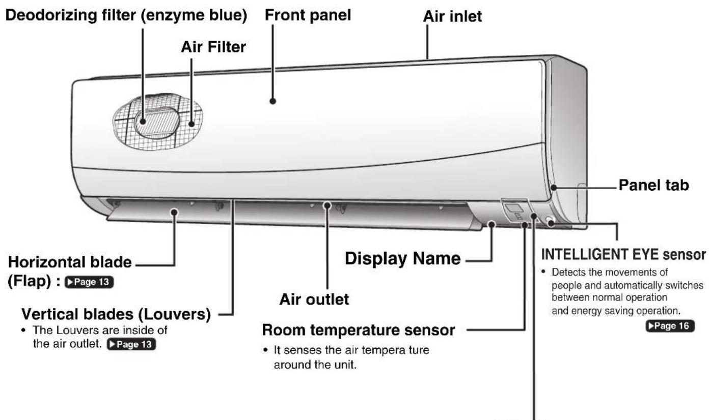
text_image
Deodorizing filter (enzyme blue) Air Filter Front panel Air inlet Horizontal blade (Flap) : ▶ Page 13 Vertical blades (Louvers) • The Louvers are inside of the air outlet. ▶ Page 13 Display Name Air outlet Room temperature sensor • It senses the air tempera ture around the unit. Panel tab INTELLIGENT EYE sensor • Detects the movements of people and automatically switches between normal operation and energy saving operation. ▶Page 16Display
Signal receiver
- It receives signals from the remote controller.
- When the unit receives a signal, you will hear a short beep.
• Operation start ..... beep-beep - Settings changed .... beep
• Operation stop ...... beeeeeep

text_image
Operation lamp (green) TIMER lamp (orange) : ▶Page 20,21,22,25,27 ON/OFF INTELLIGENT EYE lamp (green) : ▶Page 16Indoor Unit ON/OFF switch
- Push this switch once to start operation. Push once again to stop it.
- The operation mode refer to the following table.
| Mode | Temperature setting | Airflow rate |
| COOL | 22°C | AUTO |
- This switch can be used when the remote controller is missing.
■ Open the front panel
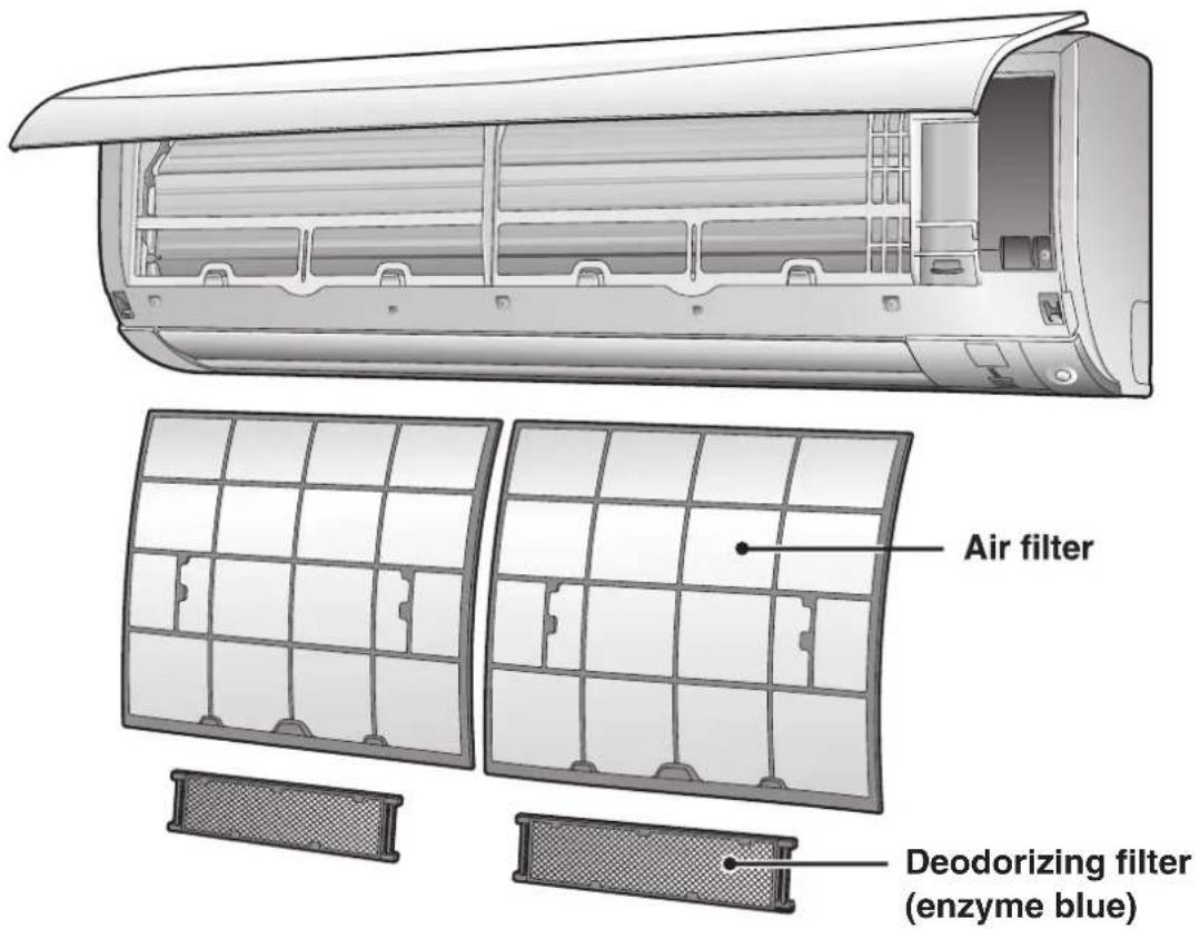
text_image
Air filter Deodorizing filter (enzyme blue)Outdoor Unit
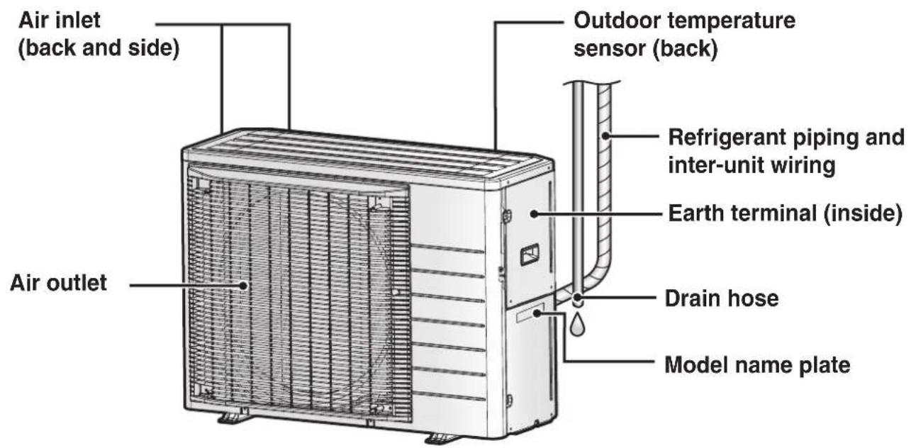
text_image
Air inlet (back and side) Outdoor temperature sensor (back) Refrigerant piping and inter-unit wiring Earth terminal (inside) Drain hose Model name plate Air outletNames of Parts
Remote Controller

text_image
Signal transmitter Receiver To use the remote controller, aim the transmitter at the indoor unit. If there is anything blocking the signals between the unit and the remote controller, such as a curtain, the unit may not operate. The maximum transmission distance is about 7m. Display (LCD) Displays the current settings. (In this illustration, each section is shown with all its displays on for the purpose of explanation.) TEMPERATURE adjustment button Changes the temperature setting. ▶ Page 12 FAN setting button Selects the airflow rate setting. ▶ Page 14 POWERFUL button POWERFUL operation. ▶ Page 18 ON/OFF button Press this button once to start operation. Press once again to stop it. ▶ Page 11 Front cover Open the front cover. ▶ Page 8 Model name ARC466A29■ Open the front cover

text_image
MODE selector button • Selects the operation mode. (DRY/COOL/FAN) ▶ Page 11 ECONO/QUIET button • ECONO/OUTDOOR UNIT QUIET operation. ▶ Page 19 SENSOR button • INTELLIGENT EYE operation. ▶ Page 16 COMFORT button • COMFORT AIRFLOW operation. ▶ Page 15 SWING button • Adjusts the airflow direction. ▶ Page 13 OFF TIMER button (NIGHT SET mode) ▶ Page 21 TIMER CANCEL button • Cancels the timer setting. ▶ Page 20,21 • Cannot be used for the WEEKLY TIMER operation. SELECT button • Changes the clock, ON/OFF TIMER and WEEKLY TIMER settings. Timer Copy Back Select On Cancel Off Cancel Timer + - ▼ ON TIMER button ▶ Page 20 CLOCK button ▶ Page 10Preparation Before Operation
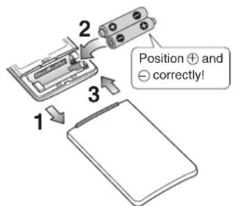
text_image
Position + and - correctly!*The remote controller may differ from some models.
To insert the batteries
- Slide the front cover to take it off.
- Insert 2 dry batteries AAA.LR03 (alkaline).
- Replace the front cover.

text_image
Remote controller Screws Remote controller holderTo fix the remote controller holder to a wall
- Choose a place from where the signals reach the unit.
- Fix the holder to a wall, a pillar, or similar location with the screws supplied with the holder.
- Place the remote controller in the remote controller holder.
Turn on the circuit breaker
- After the power is turned on, the flaps of the indoor unit open and close once to set the reference position.
NOTE
Notes on batteries
- When replacing the batteries, use batteries of the same type, and replace both old batteries together.
- The batteries will last for about 1 year. If the remote controller display begins to fade and the possible transmission range becomes shorter within a year, however, replace both batteries with new, size AAA.LR03 (alkaline).
- The batteries supplied with the remote controller are for initial operation. The batteries may run out in less than 1 year.
Note on remote controller
- Do not drop the remote controller. Do not get it wet.

text_image
27.0°C MON 15:30 Select Timer*The remote controller may differ from some models.
To set the clock
1. Press

"0.00 is displayed on the LCD.
"MON" and "④ blink.
2. Press Select to set the current day of the week.
3. Press

“ @ blinks.
4. Press to set the clock to the present time.
- Holding down ▲ or ▼ rapidly increases or decreases the displayed time.
5. Press
- Point the remote controller at the indoor unit when pressing the buttons.
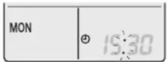
“*” blinks.
NOTE
Note on setting the clock
- If the indoor unit's internal clock is not set to the correct time, the ON/OFF TIMER and WEEKLY TIMER will not operate punctually.
DRY · COOL · FAN Operation
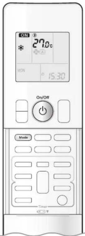
text_image
ON 27.0°C * ON MON 15:30 On/Off Mode TimerThe air conditioner operates with the operation mode of your choice.
From the next time on, the air conditioner will operate with the same operation mode.
To start operation
1. Press and select a operation mode.
• Each pressing of the button changes the mode setting in sequence.
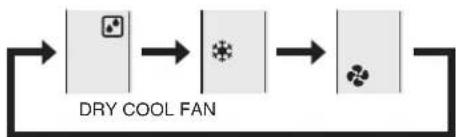
flowchart
graph LR
    A["DRY COOL FAN"] --> B["Product"]
    B --> C["Product"]
2. Press On/Off
• “ ON displayed on the LCD.
• The OPERATION lamp lights green.
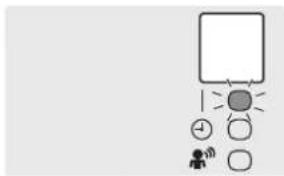
text_image
Simple diagram with a rectangle, sun, and icons including a person, a Wi-Fi signal, and a circle with plus sign.Display
To stop operation
Press again.
• “ On appears from the LCD.
• The OPERATION lamp goes off.
NOTE
Note on DRY operation
- Eliminates humidity while maintaining the indoor temperature as much as possible. It automatically controls temperature and airflow rate, so manual adjustment of these functions is unavailable.
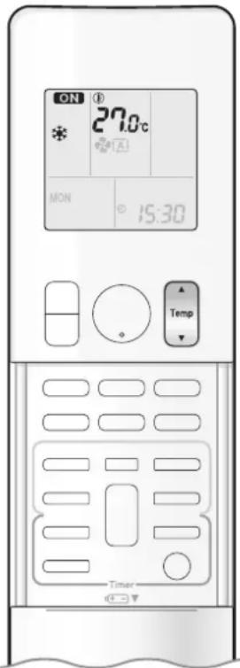
text_image
ON 27.0°C * * A1 MON 15:30 Temp TimerTo change the temperature setting

Press

- Press ▲ to raise the temperature and press ▼ to lower the temperature.
| COOL operation | DRY or FAN operation |
| 18.0 – 32.0°C | The temperature setting cannot be changed. |
Tips for saving energy
Keeping the temperature setting at a moderate level helps save energy.
- Recommended temperature setting
- For cooling : 26.0-28.0°C
Cover windows with a blind or a curtain.
- Blocking sunlight and air from outdoors increases the cooling effect.
Keep the air filters clean.
- Clogged air filters cause inefficient operation and waste energy. Clean them once in about every 2 weeks. ▶ Page 31

natural_image
Stylized plant branch illustration with leaves and stems, rendered in grayscale geometric shapes (no text or symbols)If you are not going to use the air conditioner for a long period, for example in spring or autumn, turn off the circuit breaker.
- The air conditioner always consumes a small amount of electricity even while it is not operating.

Adjusting the Airflow Direction

text_image
MASTER * 27.0°C A MON 15:30 Switch TimerYou can adjust the airflow direction to increase your comfort.
ATTENTION
• Always use a remote controller to adjust the angles of the flaps and louvres.
- If you attempt to move the flaps and louvres forcibly by hand when they are swinging, the mechanism may be damaged.
- Inside the air outlet, a fan is rotating at a high speed.
To start auto swing
Up and down airflow direction

Press

- “C” is displayed on the LCD.
- The flaps (horizontal blades) will begin to swing.
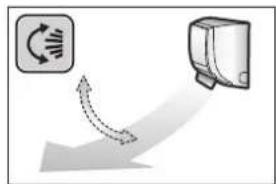
natural_image
Diagram showing a circular icon with rotation arrows and a server icon, no text or symbols presentRight and left airflow direction

Press

- “” is displayed on the LCD.
• The louvres (vertical blades) will begin to swing.

natural_image
Diagram showing airflow around a car with a curved arrow indicating direction (no text or symbols)The 3-D airflow direction

Press

- “ ⏻” and “ 📋” are displayed on the LCD.
• The flaps and louvres move in turn. - To cancel 3-D airflow, press either 📁 or again. The flaps or louvres will stop moving.

natural_image
Diagram showing airflow around a car air conditioner unit (no text or symbols)To set the flaps or louvres at the desired position
- This function is effective while the flaps or louvres are in auto swing mode.

sserP

whandthe flaps or louvres
reach the desired position.
• In the 3-D airflow, the flaps and louvres move in turn.
- “” or “” disappears from the LCD.

Adjusting the Airflow Rate

text_image
27:00 MON 15:30 FanYou can adjust the airflow rate to increase your comfort.
To adjust the airflow rate setting

• Each pressing ☐ of changes the airflow rate setting in sequence.
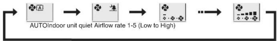
flowchart
graph LR
    A["AUTOIndoor unit quiet Airflow rate 1-5 (Low to High)"] --> B["AUTOIndoor unit quiet Airflow rate 1-5 (Low to High)"]
    B --> C["AUTOIndoor unit quiet Airflow rate 1-5 (Low to High)"]
    C --> D["AUTOIndoor unit quiet Airflow rate 1-5 (Low to High)"]
- When operation starts and noise from the indoor unit will become quieter.
- In the quiet operation mode, the airflow rate is set to a weak level.
| COOL and FAN operation DRY operation | |
| The airflow rate setting cannot be changed. |
NOTE
Note on airflow direction setting
- The movable range of the flaps varies according to the operation mode.
Movable range of the flap
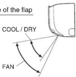
text_image
of the flap COOL / DRY FANNote on 3-D airflow
- Using 3-D airflow circulates cold air, which tends to collected at the bottom of the room, and hot air, which tends to collect near the ceiling, throughout the room, preventing areas of cold and hot developing.
Note on airflow rate setting
- At smaller airflow rates, the cooling effect is also smaller.
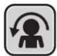
COMFORT AIRFLOW Operation

text_image
27.0°C MON 15:30 Comfort TimerCOMFORT AIRFLOW operation: The air direction and flow rate are adjusted so that the air will not blow directly at people in the room.
To start COMFORT AIRFLOW operation

- “ 🍴 is displayed on the LCD.
| COOL and DRY operation FAN operation | ||
| Flap direction | Goes up | Not available |
| Airflow rate | AUTO | |
To cancel COMFORT AIRFLOW operation
Press again.
• “ disappears from the LCD.
- The flap will return to the memory position from before COMFORT AIRFLOW operation.
Notes on "COMFORT AIRFLOW Operation"
• The flap position will change, preventing air from blowing directly on the occupants of the room.
- POWERFUL operation and COMFORT AIRFLOW operation cannot be used at the same time.
- The volume of air will be set to AUTO. If the upward and downward airflow direction is selected, the COMFORT AIRFLOW function will be canceled.
- Priority is given to the function of whichever button is pressed last.
- The COMFORT AIRFLOW function makes the following airflow direction adjustments. The flaps will move upward while cooling so that the airflow will be directed upward.
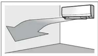
natural_image
Diagram of a airflow or ventilation system with a car on a wall (no text or symbols)Cooling operation

INTELLIGENT EYE Operation
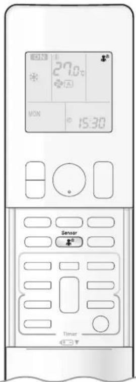
text_image
27.0°C MON 15:30 Sensor TimerThe INTELLIGENT EYE operation detects human movement. If no one is detected in the room for more than 20 minutes, the unit automatically enters energy saving operation.
CAUTION
- Do not place large objects near the INTELLIGENT EYE sensor. Also keep heating units and humidifi ers outside the sensor's detection area. This sensor can detect undesirable objects.
- Do not hit or violently push the INTELLIGENT EYE sensor. This can lead to damage and malfunction.
To start INTELLIGENT EYE operation
DPress

and select the desired model.
• Each time is pressed, a different setting option is displayed on the LCD.
• The INTELLIGENT EYE lamp lights green.
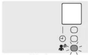
text_image
Simple diagram with a person, clock, and sun icons, possibly representing a conceptual or symbolic representation.Display

flowchart
graph LR
    A["Sensor"] --> B["blank"]
    B --> C["No Setting Intelligent eye"]
- The lamp lights when human movement is detected.
To cancel the INTELLIGENT EYE operation
Press

button.
• The INTELLIGEN EYE lamp goes off.

INTELLIGENT EYE Operation
The INTELLIGENT EYE operation detects human movement.
If no one is detected in the room for more than 20 minutes, the unit automatically enters energy saving operation.
INTELLIGENT EYE operation is useful for energy saving
■ People is detected in the sensing area.

natural_image
Illustration of a person sitting on a couch with an adult, under a spotlight beam (no text or symbols)The air conditioner is in normal operation while the sensor is detecting human movement.
■ No people are detected in the sensing area.
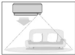
natural_image
Diagram showing a car receiving airfare lighting from a sofa, with no text or symbols present.The air conditioner will switch to energy-saving mode after 20 minutes.
Energy saving operation
- If no presence detected in the room for 20 minutes, energy saving operation starts automatically.
- This operation changes the temperature by +2^ in COOL / +2^ in DRY operation from the set temperature.
When the room temperature exceeds 30^ C, the operation changes the temperature by +1^ C in COOL / +1^ C in DRY operation from the set temperature. - This operation decreases the airflow rate slightly in FAN operation only.
NOTE
Note on COMFORT AIRFLOW operation
- The airflow rate will be set to AUTO. If the up and down airflow direction is selected, COMFORT AIRFLOW operation will be cancelled.
Notes on INTELLIGENT EYE operation
- Application range is as follows.
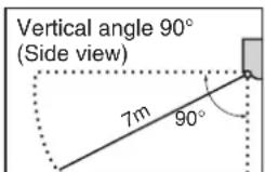
text_image
Vertical angle 90° (Side view) 7m 90°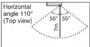
text_image
Horizontal angle 110° (Top view) 55° 55° 7m- The sensor may not detect moving objects further than 7m away. (Please see the application range)
- Sensor detection sensitivity changes according to the indoor unit location, the speed of passers-by, temperature range, etc.
- The sensor could also mistakenly detect pets, sunlight, fluttering curtains and light reflected off of mirrors as passers-by.
• INTELLIGENT EYE operation will not switch on during POWERFUL operation. - NIGHT SET mode ▶ Page 21 will not switch on during use of INTELLIGENT EYE operation.
Note on combination of COMFORT AIRFLOW operation and INTELLIGENT EYE operation
- The airflow rate will be set to AUTO. If the up and down airflow direction is selected, COMFORT AIRFLOW operation will be canceled. Priority is given to the function of whichever button is pressed last.

POWERFUL Operation

text_image
ON 27.0°C MON 15:30 PowerfulPOWERFUL operation quickly maximizes the cooling effect in any operation mode. In this mode, the air conditioner operates at maximum capacity.
To start POWERFUL operation
Press during operation.
• “ Is displayed on the LCD.
- POWERFUL operation ends in 20 minutes. Then the system automatically operates again with the previous settings which were used before POWERFUL operation.
To cancel POWERFUL operation
Press again.
• “ disappears from the LCD.
NOTE
Notes on POWERFUL operation
- Pressing ⏻ causes the settings to be cancelled, and “💡” disappears from the LCD.
- POWERFUL operation will not increase the capacity of the air conditioner if the air conditioner is already in operation with its maximum capacity demonstrated.
- In COOL operation
To maximize the cooling effect, the capacity of outdoor unit increases and the airflow rate becomes fixed at the maximum setting. The temperature and airflow settings cannot be changed. - In DRY operation
The temperature setting is lowered by 2.5°C and the airflow rate is slightly increased. - In FAN operation
The airflow rate is fixed at the maximum setting.
Regarding the combination of POWERFUL and other operations
| POWERFUL + COMFORT AIRFLOW | Not available* |
| POWERFUL + ECONO | |
| POWERFUL + OUTDOOR UNIT QUIET |
*Priority is given to the function of whichever button is pressed last.

ECONO / OUTDOOR UNIT QUIET Operation

text_image
27.0°C MON 15:30 Ecoa/Outlet TimerECONO operation enables efficient operation by limiting the maximum power consumption.
This function is useful to prevent the circuit breaker from tripping when the unit operates alongside other appliances on the same circuit.
OUTDOOR UNIT QUIET operation lowers the noise level of the outdoor unit by changing the frequency and fan speed of the outdoor unit. This function is convenient during the night-time operation.
To start operation
Press Econo/Quiet and select the desired mode.
• Each time Ecano/Quiet We pressed, a different setting option is displayed on the LCD.
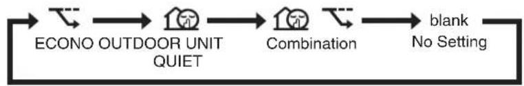
flowchart
graph LR
    A["ECONO OUTDOOR UNIT QUIET"] --> B["Combination"]
    B --> C["blank\nNo Setting"]
To cancel operation
Press Econo/Quiet until no icon is displayed.
NOTE
Notes on ECONO operation
- Pressing ⏻ causes the settings to be cancelled, and “ ” disappears from the LCD.
- If the power consumption level is already low, switching to ECONO operation will not reduce the power consumption.
Notes on OUTDOOR UNIT QUIET operation
• Even if the operation is stopped by using the remote controller or the indoor unit ON/OFF switch when using OUTDOOR UNIT QUIET operation,
"will remain lit on the remote controller display.
- OUTDOOR UNIT QUIET operation will not reduce the frequency nor fan speed if they already are operating at reduced levels.
- This operation is performed with lower power and therefore may not provide a sufficient cooling effect.
Possible combinations of ECONO / OUTDOOR UNIT QUIET operation and basic operations
| Operation mode | |||
| DRY COOL | FAN | ||
| ECONO | √ | √ | × |
| OUTDOOR UNIT QUIET | × | √ | × |

ON/OFF TIMER Operation

text_image
27.0°C ON 6:00 Select Cancel On TimerTimer functions are useful for automatically switching the air conditioner on or off at night or in the morning. You can also use the ON TIMER and OFF TIMER together.
To use ON TIMER with a 24 hour clock display (24 HOUR ON/OFF TIMER)
- Check that the clock is correct.
If not, set the clock to the present time. ▶ Page 10
• To set the ON TIMER in an hours remaining display. ▶ Page 10
1. Press On

“ 6.00 displayed on the LCD.
"ON" blinks.
- “ ⏻” and day of the week disappear from the LCD.
2. Press until the time setting reaches the point you like.
• Each pressing of either button increases or decreases the time setting by 10 minutes. Holding down either button changes the setting rapidly.
3. Press □ again.
- "ONand setting time are displayed on the LCD.
• The TIMER lamp lights orange.

flowchart
graph TD
    A[" "] --> B[" "]
    B --> C[" "]
    C --> D[" "]
    D --> E[" "]
    E --> F[" "]
    F --> G[" "]
    G --> H[" "]
    H --> I[" "]
    I --> J[" "]
    J --> K[" "]
    K --> L[" "]
    L --> M[" "]
    M --> N[" "]
    N --> O[" "]
    O --> P[" "]
    P --> Q[" "]
    Q --> R[" "]
    R --> S[" "]
    S --> T[" "]
    T --> U[" "]
    U --> V[" "]
    V --> W[" "]
    W --> X[" "]
    X --> Y[" "]
    Y --> Z[" "]
Display
To cancel ON TIMER operation
Press Cancel
- “ONand setting time disappear from the LCD.
- “💡” and day of the week are displayed on the LCD.
• The TIMER lamp goes off.
NOTE
Note on TIMER operation
- When TIMER is set, the present time is not displayed.
In the following cases, set the timer again.
• After the circuit breaker has turned off.
• After a power failure.
• After replacing the batteries in the remote controller.

ON/OFF TIMER Operation

text_image
27.0°C OFF 0:00 Off Select Cancel TimerTo use OFF TIMER with a 24 hour clock display (24 HOUR ON/OFF TIMER)
- Check that the clock is correct.
If not, set the clock to the present time. ▶ Page 10
• To set the ON TIMER in an hours remaining display. ▶ Page 10
1. Press Off
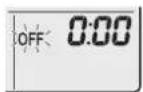
"0.08 displayed on the LCD.
"OFF" blinks.
- “ ⊕” and day of the week disappear from the LCD.
2. Press until the time setting reaches the point you like.
- Each pressing of either button increases or decreases the timem setting by 10 minutes. Holding down either button changes the time setting rapidly.
3. Press again.
- “OFF and setting time are displayed on the LCD.
• The TIMER lamp lights orange.

flowchart
graph TD
    A[" "] --> B[" "]
    B --> C[" "]
    C --> D[" "]
    D --> E[" "]
    E --> F[" "]
    F --> G[" "]
    G --> H[" "]
    H --> I[" "]
    I --> J[" "]
    J --> K[" "]
    K --> L[" "]
    L --> M[" "]
    M --> N[" "]
    N --> O[" "]
    O --> P[" "]
    P --> Q[" "]
    Q --> R[" "]
    R --> S[" "]
    S --> T[" "]
    T --> U[" "]
    U --> V[" "]
    V --> W[" "]
    W --> X[" "]
    X --> Y[" "]
    Y --> Z[" "]
Display
To cancel OFF TIMER operation
Press Cancel
- “OFF and setting time disappear from the LCD.
- “ ⊕” and day of the week are displayed on the LCD.
• The TIMER lamp goes off.
To combine ON TIMER and OFF TIMER
- A sample setting for combining the 2 timers is shown below.
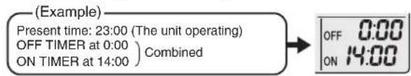
text_image
(Example) Present time: 23:00 (The unit operating) OFF TIMER at 0:00 ON TIMER at 14:00) Combined OFF 0:00 ON 14:00NOTE
NIGHT SET mode
- When the OFF TIMER is set, the air conditioner automatically adjusts the temperature setting (0.5°C up in COOL) to prevent excessive cooling during sleeping hours.
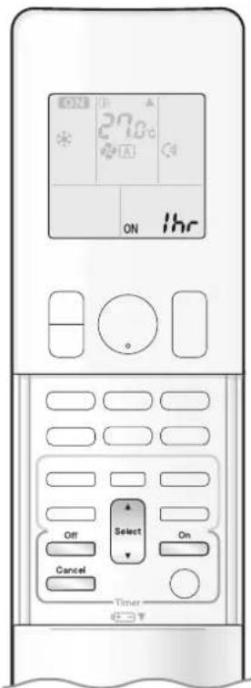
text_image
27.8°C ON ihr Select On Off Cancel TimerTo use the ON/OFF TIMER with an hours remaining display (COUNT UP-DOWN ON/OFF TIMER)
- Check that the clock is correct.
If not, set the clock to the present time. ▶ Page 10
1. Press and hold or for about 5 seconds, when signal indicator (▲) blink, release your finger from the button.

For ON TIMER
"Ibr" is displayed on the LCD.
"ON" blinks.
For OFF TIMER
"Ibr" is displayed on the LCD.
"OFF" blinks.
- “ ⏻ ” and day of the week disappear from the LCD.
2. Press until the time setting reaches the point you like.
• Each pressing of the button increases or decreases the time setting by 1 hour.
• The time can be set between 1 and 12 hours.
3. Press on or again.
- “ON” or “OFF”, and setting time are displayed on the LCD.
• The TIMER lamp lights orange.
Display
- To change the display mode from COUNT UP-DOWN ON/OFF TIMER to 24 HOUR ON/OFF TIMER, repeat STEP 1, and continue from STEP 2 of "24 HOUR ON/OFF TIMER". ▶Page 20.21
- Timer display mode cannot be changed while "ON" or "OFF" are blinking. Press ☐ or ☐ to stop the blinking.
Combining display modes
- Different display modes (24 HOUR ON/OFF TIMER and COUNT UP-DOWN ON/OFF TIMER) can be used for the ON TIMER and OFF TIMER simultaneously.
(Example)
Present time: 22:00 [unit is in operation] OFF TIMER at 1:00 (3 hours after present time) ON TIMER at 6:00 (8 hours after present time) Combined
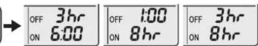
text_image
OFF 3hr ON 6:00 OFF 1:00 ON 8hr OFF 3hr ON 8hrNOTE
Notes on COUNT UP-DOWN ON/OFF TIMER
- After setting, the time displayed on the LCD will automatically count down by 1 hour for every 1 hour that passes. For example, if the OFF TIMER is set to 3 hours, the display will change as follows: 3hr 2hr 1hr blank (OFF)
Switching between ON/OFF TIMER display modes (24 hour clock and hours remaining display)
- When change display mode (from 24 HOUR ON/OFF TIMER to COUNT UP-DOWN ON/OFF TIMER or from COUNT UP-DOWN ON/OFF TIMER to 24 HOUR ON/OFF TIMER), cancel timer. So, to use timer, set timer again.

WEEKLY TIMER Operation
Up to 4 timer settings can be saved for each day of the week. This is convenient to adapt the WEEKLY TIMER to your family's life style.
Setting example of the WEEKLY TIMER
The same timer settings are used from Monday through Friday, while different timer settings are used for the weekend.
| [Monday] | Make timer settings for programmes 1-4. ▶Page 24Programme 1 Programme 2 Programme 3 Programme 4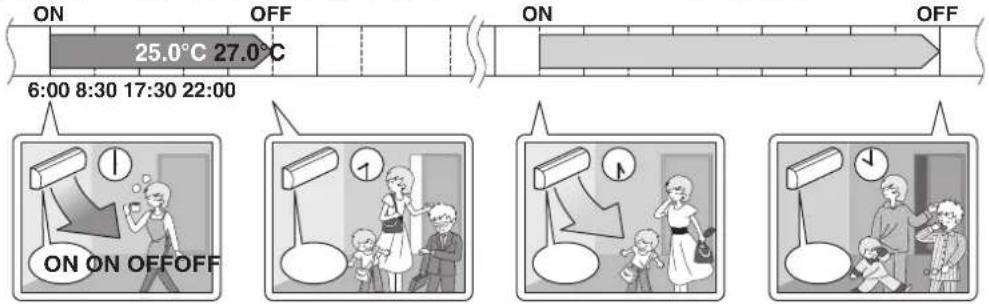 |
| [Tuesday] to [Friday] | Use thosePr |
| [Saturday] | No timer settings |
| [Sunday] | Maki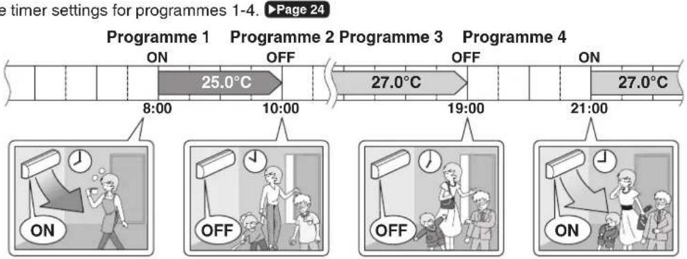 |
- Up to 4 reservations per day and 28 reservations per week can be set using the WEEKLY TIMER. The effective use of the copy mode simplifies timer programming.
- The use of ON-ON-ON-ON settings, for example, makes it possible to schedule operating mode and set temperature changes. Furthermore, by using OFF-OFF-OFF-OFF settings, only the turn off time of each day can be set. This will turn off the air conditioner automatically if you forget to turn it off.

text_image
ON 27.0°C OFF MON ON 6:00 25.0°C Select Next TimerTo use WEEKLY TIMER operation
Setting mode
- Make sure the day of the week and time are set. If not, set the day of the week and time. ▶ Page 10
Programme 1 Programme 2 Programme 3 Programme 4

text_image
[Monday] ON OFF ON OFF 25.0°C 27.0°C 6:00 8:30 17:30 22:00Setting Displays
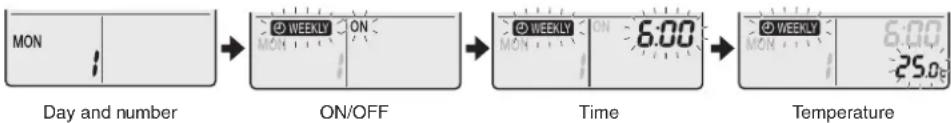
flowchart
graph LR
    A["MON"] --> B["ON/OFF"]
    B --> C["6:00"]
    C --> D["Temperature"]
1. Press
- The day of the week and the reservation number of the current day will be displayed.
- 1 to 4 settings can be made per day.
2. Press Select to select the desired day of the week and reservation number.
- Pressing ▲ Select changes the reservation number and the day of the week.
3. Press Next .
- The day of the week and reservation number will be set.
- “ WEEKLY ” and “ ON ” blink.
4. Press Select to select the desired mode.
- Pressing Select changes the "ON" or "OFF" setting in sequence.
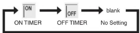
flowchart
graph LR
    A["ON"] --> B["OFF"]
    B --> C["blank"]
    D["ON TIMER"] --> A
    E["OFF TIMER"] --> B
    F["No Setting"] --> C
- In case the reservation has already been set, selecting “blank” deletes the reservation.
- Proceed to STEP 9 if "blank" is selected.
- To return to the day of the week and reservation number setting, press Back.
5. Press Next .
- The ON/OFF TIMER mode will be set.
- “WEEKLY” and the time blink.

WEEKLY TIMER Operation
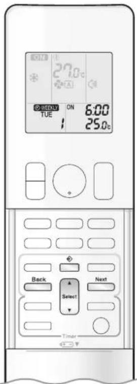
text_image
27.0°C ON TUE 6:00 25.0°C Back Select Next Timer6. Press to select the desired time.
- The time can be set between 0:00 and 23:50 in 10-minute intervals.
- To return to the ON/OFF TIMER mode setting, press Back
• Proceed to STEP 9 when setting the OFF TIMER.
7. Press Next
• The time will be set.
• “ ⏻ WEEKLY ” and the temperature blink.
8. Press to select the desired temperature.
• The temperature can be set between 10.0°C and 32.0°C.
COOL or AUTO: The unit operates at 18.0°C even if it is set to 10.0°C to 17.0°C. ▶ Page 12
HEAT or AUTO : The unit operates at 30.0°C even if it is set to 31.0°C to 32.0°C. ▶ Page 12
• To return to the time setting, press Back
- The set temperature is only displayed when the mode setting is on.
9. Press Next .
- The temperature will be set and go to the next reservation setting.
- The temperature is set while in ON TIMER operation, and the time is set while in OFF TIMER operation.
• The next reservation screen will appear.
• To continue further settings, repeat the procedure from STEP 4.
10. Press to complete the setting.
- Be sure to direct the remote controller toward the indoor unit and check for a receiving tone and blinking of the OPERATION lamp.
- “WEEKLY” is displayed on the LCD and WEEKLY TIMER operation is activated.
• The TIMER lamp lights orange.
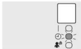
flowchart
graph TD
    A["Start"] --> B{Decision}
    B -->|Yes| C["Node 1"]
    B -->|No| D["Node 2"]
    C --> E["End"]
    D --> E
    style A fill:#fff,stroke:#000
    style E fill:#ccc,stroke:#000
Display
- A reservation made once can be easily copied and the same settings used for another day of the week. Refer to Copy mode ▶ Page 26
NOTE
Notes on WEEKLY TIMER operation
- Do not forget to set the clock on the remote controller first. ▶ Page 10
- The day of the week, ON/OFF TIMER mode, time and set temperature (only for ON TIMER mode) can be set with the WEEKLY TIMER. Other settings for the ON TIMER are based on the settings just before the operation.
- WEEKLY TIMER and ON/OFF TIMER operation cannot be used at the same time. The ON/OFF TIMER operation has priority if it is set while WEEKLY TIMER is still active. The WEEKLY TIMER will enter the standby state, and “WEEKLY” will disappear from the LCD. When the ON/OFF TIMER is up, the WEEKLY TIMER will automatically become active.
- Only the time and set temperature with the WEEKLY TIMER are sent with the ☐. Set the WEEKLY TIMER only after setting the operation mode, the airflow rate and the airflow direction ahead of time.
- Turning off the circuit breaker, power failure, and other similar events will render operation of the indoor unit's internal clock inaccurate. Reset the clock. ▶Page 10
- Back can be used only for the time and temperature settings. It cannot be used to go back to the reservation number.

text_image
ON 27.0°C A WEEKLY TUE ON 8:00 25.0°C Copy Select TimerCopy mode
- A reservation made once can be copied to another day of the week. The whole reservation of the selected day of the week will be copied.
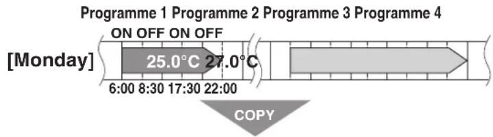
text_image
Programme 1 Programme 2 Programme 3 Programme 4 ON OFF ON OFF [Monday] 25.0°C 27.0°C 6:00 8:30 17:30 22:00 COPY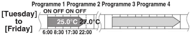
line
| Time Period | Temperature Range | | ----------------- | ----------------- | | 6:00 - 8:30 | 25.0°C | | 17:30 - 22:00 | 27.0°C |
flowchart
graph LR
    A["ON 27.0°C"] --> B["ON CP 6:00 MON 25.0°C"]
    B --> C["ON CP 6:00 TUE 25.0°C"]
    C --> D["ON 27.0°C 15:30 MON"]
- Press
- Press Select to confirm the day of the week to be copied.
- Press Copy
- The whole reservation of the selected day of the week will be copied.
- Press Select to select the destination day of the week.
-
Press Copy
-
The reservation will be copied to the selected day of the week. The whole reservation of the selected day of the week will be copied.
-
To continue copying the settings to other days of the week, repeat STEP 4 and STEP 5.
-
Press ☐ to complete the setting.
- “WEEKLY” is displayed on the LCD and WEEKLY TIMER operation is activated.
NOTE
Note on COPY MODE
- The entire reservation of the source day of the week is copied in the copy mode.
In the case of making a reservation change for any day of the week individually after copying the content of weekly reservations, press and change the settings in the steps of Setting mode. ▶ Page 24

WEEKLY TIMER Operation

text_image
ON 27.0°C ON TUE 6:00 25.0°C Weekly Select Next TimerConfirming a reservation
• The reservation can be confirmed.

text_image
Setting Displays TUE 15:30 Normal ON 6:00 TUE 25.0c Confirmation1. Press
- The day of the week and the reservation number of the current day will be displayed.
2. Press to select the day of the week and the reservation number to be confirmed.
- Pressing Select displays the reservation details.
- To change the confirmed reserved settings, select the reservation number and press Next. The mode is switched to setting mode. Proceed to Setting mode STEP 4. ▶ Page 24
3. Press to exit the confirmation mode.
- “WEEKLY” is displayed on the LCD and WEEKLY TIMER operation is activated.
• The TIMER lamp lights orange.
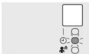
flowchart
graph TD
    A["Start"] --> B{Decision}
    B -->|Yes| C["User Icon"]
    B -->|No| D["Process Step"]
    D --> E["End"]
Display
To deactivate WEEKLY TIMER operation

Weekly sser while “WEEKLY” is displayed on the LCD.
- “ Ⓧ WEEKLY ” disappears from the LCD.
• The TIMER lamp goes off.
• To reactivate the WEEKLY TIMER operation, press □ again. - If a reservation deactivated with ☐ is activated once again, the last reservation mode will be used.
NOTE
- If not all the reservation settings are reflected, deactivate the WEEKLY TIMER operation once. Then press ☐ again to reactivate the WEEKLY TIMER operation.

text_image
ON 27.0°C A OFF/WHM ON 6:00 TUE 25.0°C Weekly Next Select TimerTo delete reservations
An individual reservation
1. Press
- The day of the week and the reservation number will be displayed.
2. Press to select the day of the week and the reservation number to be deleted.
3. Press Next
- “ WEEKLY ” and “ ON ” or “ OFF ” blink.
4. Press until no icon is displayed.
- Pressing changes the ON/OFF TIMER mode in sequence.
- Selecting "blank" will cancel any reservation you may have.

flowchart
graph LR
    A["ON"] --> B["OFF"]
    B --> C["blank"]
    D["ON TIMEROFF TIMER"] --> E["No Setting"]
5. Press Next .
- The selected reservation will be deleted.
6. Press
- If there are still other reservations, WEEKLY TIMER operation will be activated.
Reservations for each day of the week
- This function can be used for deleting reservations for each day of the week.
- It can be used while confirming or setting reservations.
1. Press Select to select the day of the week to be deleted.
2. Hold for about 5 seconds.
- The reservation of the selected day of the week will be deleted.
All reservations
Hold Weekly for about 5 seconds with the normal display.
- Be sure to direct the remote controller toward the indoor unit and check for a receiving tone.
- This operation cannot be used for the WEEKLY TIMER setting display.
- All reservations will be deleted.
Care and Cleaning

CAUTION
- Before cleaning, be sure to stop the operation and turn off the circuit breaker.
- Do not touch the aluminum fins of the indoor unit. If you touch those parts, this may cause an injury.
■ Quick reference

text_image
Cleaning parts Front panel • Wipe it with a soft damp cloth. If dirty ▶ Page 30 Air filterAir filter
• Vacuum dust or wash the filter.
Once every 2 weeks
Page 31
Indoor unit and Remote controller
- Wipe them with a soft cloth.
If dirty
Deodorizing filter (enzyme blue)
To purchase the filters (Table 1) or to purchase the another type, contact the dealer where you bought the air conditioner. The method of cleaning and replacement of the filters may differ depending on the model. Refer to the label attached to the separately sold filters themselves.
Table 1
| Item Part No. | |
| Air quality filter (enzyme blue with PM 2.5) - without frame (set of 2) | BAFP094A43 |
| Deodorizing filter (enzyme blue) - without frame (set of 2) | BAFP094A41 |
| Dust collection filter (PM 2.5) - without frame (set of 2) | BAFP046A41 |
| Titanium apatite deodorizing filter - without frame (set of 2) | KAF970A46 |
Deodorizing filter (enzyme blue), Titanium apatite deodorizing filter.
• Vacuum dust or replace the filter. [Cleaning] [Replacement]
Once every 6 months
Once every 3 years
Page 32
Air quality filter (enzyme blue with PM 2.5), Dust collection filter (PM 2.5)
- No cleaning is required. Please replace the filter every 6 months. ▶ Page 32
NOTE
For cleaning, do not use any of the following:
• Water hotter than 40.0°C
• Volatile liquid such as benzene, petrol and thinner
- Polishing compounds
- Rough materials such as a scrubbing brush
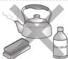
natural_image
Illustration of a kettle, a beaker with a grater, and a bottle labeled 'Benzene' (no text or symbols on objects)
CAUTION
- When removing or attaching the front panel, stand on a solid, stable base and take care not to fall.
- When removing or attaching the front panel, support the panel securely with your hand to prevent it from falling.
■ Front panel
1. Open the front panel.
- Hold the front panel by the panel tabs on the 2 sides and open it.

text_image
Panel tab2. Remove the front panel.
- Slide the front panel to either the left or right and pull it toward you. This will disconnect the front panel shaft on one side.

text_image
2) Pull Front panel shaft 1) Slide 2) Pull 1) Slide- Disconnect the front panel shaft on the other side in the same manner.
3. Clean the front panel.
- Wipe it with a soft damp cloth.
- Only neutral detergent may be used.
- In case of washing the panel with water, wipe it with a dry soft cloth, and let it dry in the shade after washing.
4. Attach the front panel.
- Align the front panel shaft on the left and right of the front panel with the grooves, then push them all the way in.
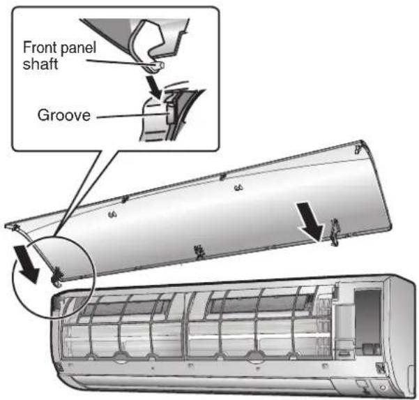
text_image
Front panel shaft Groove5. Close the front panel slowly.
- Press the front panel at both sides and thecentre.
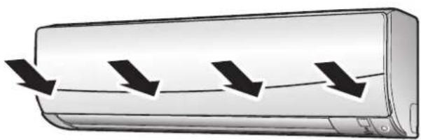
natural_image
Illustration of a car air conditioner with airflow arrows indicating airflow direction (no text or symbols)- Make sure that the front panel is securely fixed.
Care and Cleaning
Air filter
1. Open the front panel. ▶ Page 30

natural_image
Diagram of an air conditioner unit showing airflow direction and component layout (no text or symbols)2. Pull out the air filters.
- Push the filter tab at the centre of each air filter a little upwards, then pull it down.

text_image
1) Push 2) Pull down3. Wash the air filters with water or clean them with a vacuum cleaner.
- It is recommended to clean the air filters every 2 weeks.

natural_image
Illustration of hands holding a grid-based device with a tool, no text or symbols visibleIf the dust does not come off easily
- Wash the air filters with neutral detergent thinned with lukewarm water, then let them dry in the shade.
- Be sure to remove the filter (small). Refer to "Filter (small)" on the next page.
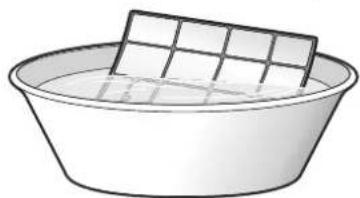
natural_image
Simple line drawing of a basin with a rectangular dish on top (no text or symbols)- Set the filters as they were.
- Close the front panel slowly.
Page 30
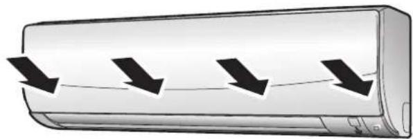
natural_image
Illustration of a car with four downward arrows indicating airflow or cooling process (no text or symbols)■ Filter (small)
* For the applicable filter type, please refer to ▶ Page 29.
Attaching
-
Open the front panel and pull out the air filters. ▶ Page 31
-
Insert the filter.
- Check that the filters are inserted securely under the tabs.
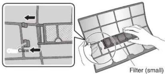
text_image
Claw Filter (small)Cleaning and Replacement
-
Open the front panel and pull out the air filters. ▶ Page 31
-
Take off the filter.
- Hold the recessed parts of the frame and unhook the 4 claws.
- Remove the filters from the tabs.
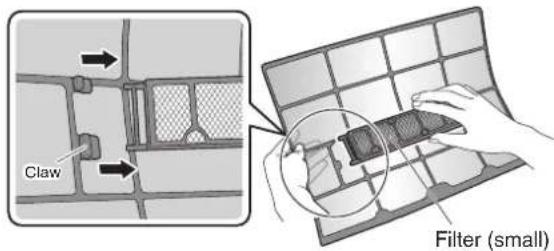
text_image
Claw Filter (small)NOTE
• Operation with dirty filters:
- cannot deodorise the air,
- cannot clean the air,
– results in poor cooling,
- may cause odour.
- Dispose of old filters as non-flammable waste.
- Clean or replace.
[Cleaning]
Deodorizing filter (enzyme blue) : Blue / Titanium apatite deodorizing filter : Blue-Black
3-1 Vacuum dust, and soak in lukewarm water or water for about 10 to 15 minutes if very dirty.
3-2 After washing, shake off remaining water and let them dry in the shade.
- This filter can be renewed by washing it with water once every 6 months and we recommend replacing it once every 3 years.
- Do not wiring out the filter when removing water from it.
Air quality filter (enzyme blue with PM 2.5) : Blue-White / Dust collection filter (PM 2.5) : White
- Do not wash the filters as this will reduce their efficiency.
- It is recommended to replace it once every 6 months.
[Replacement]
Remove the filter from the filter frame and prepare a new one.
- Do not throw away the filter frame.
- Reuse the filter frame when replacing the filter.
- When attaching the filter, check that the filter is properly set in the tabs.
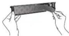
- Set the filters as they were and close the front panel.
- Press the front panel at both sides and the center.
Care and Cleaning
■ Prior to a long period of non-use
1. Operate the FAN mode for several hours on a fine day to dry out the inside.
- Press Mode and select "♣".
- Press On/Off and start the operation.
2. After operation stops, turn off the circuit breaker for the room air conditioner.
3. Take out the batteries from the remote controller.
■ We recommend periodical maintenance
- In certain operating conditions, the inside of the air conditioner may get foul after several seasons of use, resulting in poor performance. It is recommended to have periodical maintenance by a specialist in addition to regular cleaning by the user.
- For specialist maintenance, please contact the dealer where you bought the air conditioner.
- The maintenance cost must be borne by the user.
FAQ
Indoor unit
The flaps do not start swinging immediately.
- The air conditioner is adjusting the position of the flaps. The flaps will start moving soon.
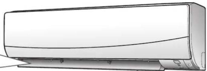
natural_image
Line drawing of a wall-mounted air conditioner unit (no text or symbols)Operation does not start soon.
■ When was pressed soon after operation was stopped.
■ When the mode was reselected.
• This is to protect the air conditioner. You should wait for about 3 minutes.
Different sounds are heard.
■ A sound like flowing water
- This sound is generated because the refrigerant in the air conditioner is flowing.
- This is a pumping sound of the water in the air conditioner and can be heard when the water is pumped out from the air conditioner during COOL or DRY operation.
- The refrigerant flows in the air conditioner even if the air conditioner is not working when the indoor units in other rooms are in operation.
■ Blowing sound
- This sound is generated when the flows of the refrigerant in the air conditioner is switched over.
■ Ticking sound
- This sound is generated when the cabinet and frame of the air conditioner slightly expand or shrink as a result of temperature changes.
■ Whistling sound
- This sound is generated when refrigerant flows during defrosting operation.
■ Clicking sound during operation or idle time
- This sound is generated when the refrigerant control valves or the electrical parts operate.
■ Clopping sound
- This sound is heard from the inside of the air conditioner when the exhaust fan is activated while the room doors are closed. Open the window or turn off the exhaust fan.
■ Rotating machinery causes sound
- Sound is heard when the vertical swing flaps and the horizontal swing flaps move.
- When the air conditioner is operating in a quiet environment and the airflow rate of the indoor unit is set to Quiet Mode or Low Mode, the motion of the swing flaps may cause sound.
Outdoor unit
The outdoor unit emits water.
In COOL or DRY operation
- Moisture in the air condenses into water on the cool surface of the outdoor unit piping and drips.

natural_image
Line drawing of a large industrial air conditioning unit with cooling fins and ventilation grilles (no text or symbols)Troubleshooting
Before making an inquiry or a request for repair, please check the following.
If the problem persists, consult your dealer.

Not trouble
These cases are not troubles.

Check
Please check again before requesting repairs.
The air conditioner does not operate
| Case Description / what to check | |
| OPERATION lamp is off. | Has the circuit breaker been tripped or the fuse blown?Is there a power failure?Are batteries set in the remote controller? |
| OPERATION lamp is blinking. | Turn off the power with the circuit breaker and restart operation with the remote controller.If the OPERATION lamp is still blinking, check the error code and consult your dealer. |
The air conditioner suddenly stops operating
| Case Description / what to check | |
| OPERATION lamp is on. | To protect the system, the air conditioner may stop operating after sudden large voltage fluctuations. It automatically resumes operation in about 3 minutes. |
| OPERATION lamp is blinking. | Is there anything blocking the air inlet or air outlet of the indoor unit or outdoor unit? Stop operation and after turning off the circuit breaker, remove the obstruction. Then restart operation with the remote controller. If the OPERATION lamp is still blinking, check the error code and consult your dealer. ▶ Page 38 |
The air conditioner does not stop operating
| Case Description / what to check | |
| The air conditioner continues operating even after operation is stopped. | ☑ Immediately after the air conditioner is stopped• The outdoor unit fan continues rotating for about another 1 minute to protect the system.• While the air conditioner is not in operation• When the outdoor temperature is high, the outdoor unit fan may start rotating to protect the syste. |
The room does not cool down
| Case Description / what to check | |
| Air does not come out. | When the air conditioner operates immediately after the circuit breaker is turned onThe air conditioner is preparing to operate. Wait for about 3 to 15 minutes. |
| Air does not come out / Air comes out. | Is the airflow rate setting appropriate?Is the airflow rate setting low, such as “Indoor unit quiet” or “1”? Increase the airflow rate setting.Is the set temperature appropriate?Is the adjustment of the airflow direction appropriate? |
| Air comes out. | Is there any furniture directly under or beside the indoor unit?Is the air conditioner in ECONO operation or OUTDOOR UNIT QUIET operation?Are the air filters dirty?Is there anything blocking the air inlet or air outlet of the indoor unit or outdoor unit?Is a window or door open?Is an exhaust fan turning? |
Mist comes out
| Case Description / what to check | |
| Mist comes out of the indoor unit. | This happens when the air in the room is cooled into mist by the cold airflow during COOL or other operation. |
Remote controller
| Case Description / what to check | |
| The unit does not receive signals from the remote controller or has a limited operating range. | The batteries may be exhausted.Replace both batteries with new dry batteries AAA.LR03 (alkaline).For details, refer to “Preparation Before Operation”. ▶Page 9Signal communication may be disabled if an electronic-starter-type fluorescent lamp (such as inverter-type lamps) is in the room. Consult your dealer if that is the case.The remote controller may not function correctly if the transmitter is exposed to direct sunlight. |
| LCD is faint, is not working, or the display is erratic. | The batteries may be exhausted.Replace both batteries with new dry batteries AAA.LR03 (alkaline).For details, refer to “Preparation Before Operation”. ▶Page 9 |
| Other electric devices start operating. | If the remote controller activates other electric devices, move them away or consult your dealer. |
Air has an odour
| Case Description / what to check | |
| The air conditioner gives off an odour. | The room odour absorbed in the unit is discharged with the airflow.We recommend you to have the indoor unit cleaned. Please consult your dealer. |
Others
| Case Description / what to check | |
| The air conditioner suddenly starts behaving strangely during operation. | The air conditioner may malfunction due to lightning or radio.If the air conditioner malfunctions, turn off the power with the circuit breaker and restart the operation with the remote controller. |
| The ON/OFF TIMER does not operate according to the settings. | Check if the ON/OFF TIMER and the WEEKLY TIMER are set to the same time.Change or deactivate the settings in the WEEKLY TIMER. ▶Page 23 |
Notes on the operating conditions
- If operation continues under any conditions other than those listed in the table,
- A safety device may activate to stop the operation.
- Dew may form on the indoor unit and drip from it when COOL or DRY operation is selected.
| Mode | Operating conditions |
| DRY | Outdoor temperature : -10.0-46.0°CIndoor temperature : 18.0-32.0°CIndoor humidity : 80% max. |
| COOL | Outdoor temperature : -10.0-46.0°CIndoor temperature : 18.0-32.0°CIndoor humidity : 80% max. |
Troubleshooting
■ Call your dealer immediately

WARNING
When an abnormality (such as a burning smell) occurs, stop operation and turn off the circuit breaker.
- Continued operation in an abnormal condition may result in troubles, electric shocks or fire.
- Consult the dealer where you bought the air conditioner.
Do not attempt to repair or modify the air conditioner by yourself.
- Incorrect work may result in electric shocks or fire.
- Consult the dealer where you bought the air conditioner.
If one of the following symptoms takes place, call your dealer immediately.
- The power cord is abnormally hot or damaged.
- An abnormal sound is heard during operation.
- The circuit breaker, a fuse, or the earth leakage circuit breaker cuts off the operation frequently.
- A switch or a button often fails to work properly.
• There is a burning smell.
• Water leaks from the indoor unit.
Turn off the circuit breaker and call your dealer.

■ After a power failure
- The air conditioner automatically resumes operation in about 3 minutes. You should just wait for a while.
Lightning
- If there is a risk lightning could strike in the neighbourhood, stop operation and turn off the circuit breaker to protect the system.
■ Disposal requirements
- Dismantling of the unit, handling of the refrigerant, oil and other parts, should be done in accordance with the relevant local and national regulations.
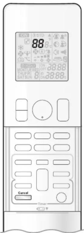
text_image
ON 88 STD ON OFF ON MONTLEWED THUFRI SATSUN ON 38:88 ON 38:88 Cancel Timer■ Fault diagnosis by remote controller
- The remote controller can receive relevant error codes from the indoor unit.
-
When is held down for about 5 seconds, "00" blinks in the temperature display section.
-
Press repeatedly until a continuous beep is produced.
- The code indication changes as shown below, and notifies you with a long beep.
| CODE MEANING | ||
| SYSTEM | 00NORMAL | |
| UAINDOOR | OUTDOOR UNIT COMBINATION FAULT | |
| U0REFRIGERANT SHORTAGE | ||
| U2DROP VOLTAGE OR MAIN CIRCUIT OVERVOLTAGE | ||
| U4FAILURE OF TRANSMISSION (BETWEEN INDOOR UNIT AND OUTDOOR UNIT) | ||
| INDOOR UNIT | A1INDOOR | PCB DEFECTIVENESS |
| A5 | HIGH PRESSURE CONTROL OR FREEZE-UP PROTECTOR | |
| A6FAN MOTOR FAULT | ||
| C4 | FAULTY HEAT EXCHANGER TEMPERATURE SENSOR | |
| C9 | FAULTY SUCTION AIR TEMPERATURE SENSOR | |
| OUTDOOR UNIT | EACOOLING-HEATING SWITCHING ERROR | |
| E1CIRCUIT BOARD FAULT | ||
| E5OL STARTED | ||
| E6FAULTY | COMPRESSOR START UP | |
| E7 | DC FAN MOTOR FAULT | |
| E8OVERCURRENT INPUT | ||
| F3 | HIGH TEMPERATURE DISCHARGE PIPE CONTROL | |
| F6HIGH PRESSURE CONTROL (IN COOLING) | ||
| H0 SENSOR FAULT | ||
| H6 | OPERATION HALT DUE TO FAULTY POSITION DETECTION SENSOR | |
| H8 DC CURRENT SENSOR FAULT | ||
| H9 | FAULTY SUCTION AIR TEMPERATURE SENSOR | |
| J3 | FAULTY DISCHARGE PIPE TEMPERATURE SENSOR | |
| J6 | FAULTY HEAT EXCHANGER TEMPERATURE SENSOR | |
| L3 | ELECTRICAL PARTS HEAT FAULT | |
| L4 | HIGH TEMPERATURE AT INVERTER CIRCUIT HEATSINK | |
| L5OUTPUT OVERCURRENT | ||
| P4 | FAULTY INVERTER CIRCUIT HEATSINK TEMPERATURE SENSOR | |
NOTE
- A short beep and 2 consecutive beeps indicate non-corresponding codes.
- To cancel the code display, hold □ down for about 5 seconds. The code display also clears if no button is pressed for 1 minute.
Quick Reference
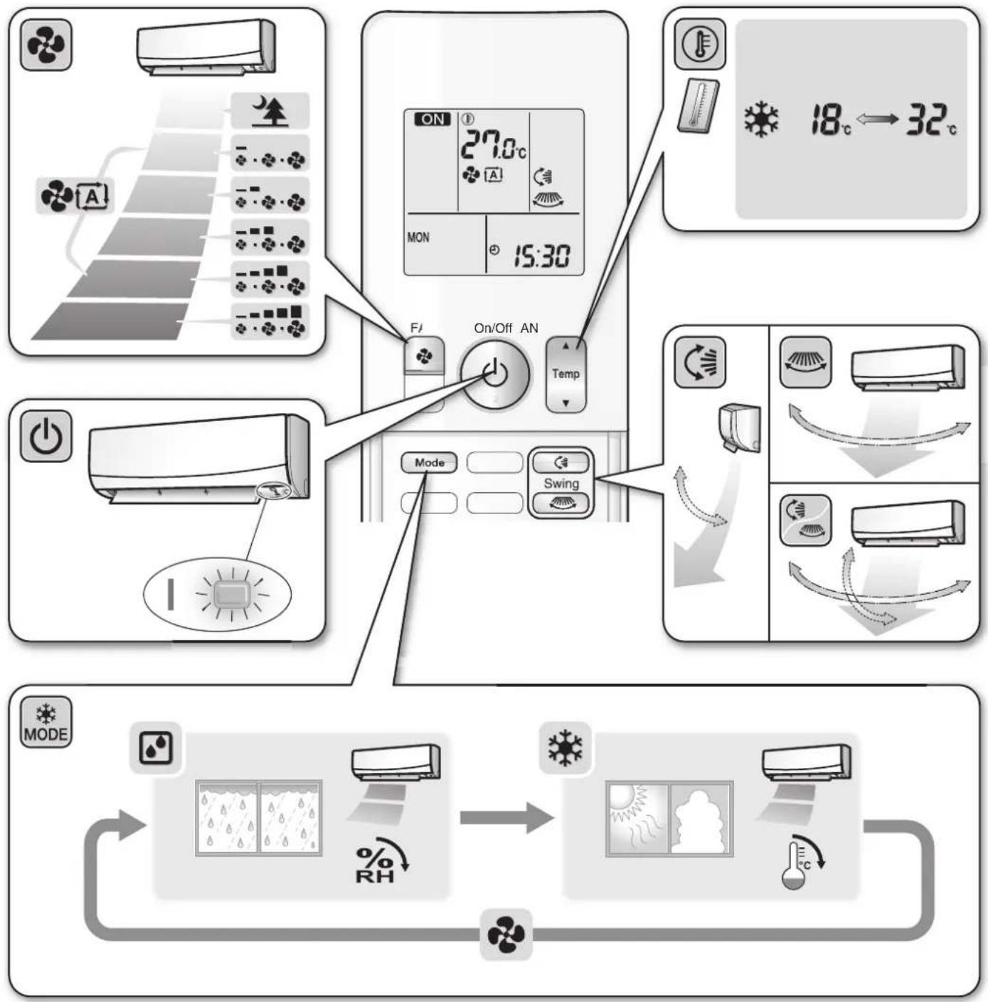
flowchart
graph TD
    A["Top Panel: Air Condition"] --> B["On/Off AN"]
    B --> C["Mode"]
    B --> D["Swing"]
    B --> E["ON"]
    E --> F["27.0°C"]
    F --> G["MON 15:30"]
    G --> H["18°C ↔ 32°C"]
    I["Bottom Panel: Weather Control"] --> J["Mode"]
    J --> K["% RH"]
    K --> L["Recovery to Air"]
    L --> M["Recovery to Air"]
    M --> N["Recovery to Air"]
DAIKIN INDUSTRIES, LTD.
Head office:
Umeda Center Bldg., 2-4-12, Nakazaki-Nishi,
Kita-ku, Osaka, 530-8323 Japan
Tokyo office:
JR Shinagawa East Bldg., 2-18-1, Konan,
Minato-ku, Tokyo, 108-0075 Japan
https://www.daikin.com

The two-dimensional bar code is a manufacturing code.