FTHI740K - Range hood Halifax - Free user manual and instructions
Find the device manual for free FTHI740K Halifax in PDF.

User questions about FTHI740K Halifax
0 question about this device. Answer the ones you know or ask your own.
Ask a new question about this device
Download the instructions for your Range hood in PDF format for free! Find your manual FTHI740K - Halifax and take your electronic device back in hand. On this page are published all the documents necessary for the use of your device. FTHI740K by Halifax.
USER MANUAL FTHI740K Halifax
Installation, Operation, and Maintenance Manual
natural_image
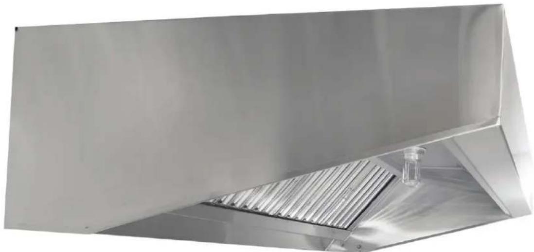
Exterior view of a stainless steel HVAC duct with ventilation grilles and a small water tank (no text or symbols visible)HalifaxHoods™
Receiving and Inspection
DESCRIPTION OF ASSEMBLIES
421FTHI - Food Truck Hood with Integrated fan
Front as low as 4", Rear ranging from 14" - 24"
text_image
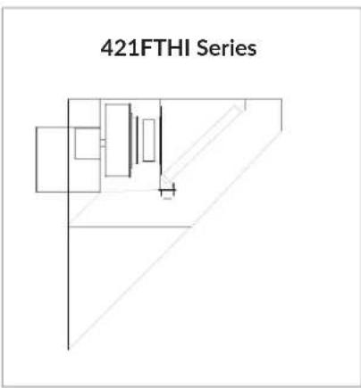
421FTHI SeriesSave these instructions. This document is the property of the owner of the equipment. Leave this document with the owner when installation or service is complete.
HalifaxHoods™
WARNING!!
Installation of this equipment should only be performed by a qualified professional. Please read this manual thoroughly before installing or servicing this equipment.
Care must be taken when cleaning the impeller to remove grease and other foreign particles. Damage to the impeller can occur if it is hit or if pressure is applied causing the impeller to be distorted. Either case can cause serious vibration and damage to the blower.
LISTINGS
This hood is UL710 and CAN/ULC S646-10 (Re-affirmed 2016) Listed when installed in accordance with these installation instructions and National Fire Protection Association Standard “NFPA 96, Removal of Smoke and Grease-Laden Vapors from Commercial Cooking Equipment”.
This hood is ANSI/NSF2-2015 Listed for the Standard for Food Equipment, Revised June 2016.
This hood is ANSI/NSF51-2014 Listed for the Standard for Food Equipment Materials, Revised March 2015.
This hood is ANSI/UL 705 (seventh edition – October 8, 2018) Listed when installed in accordance with these installation instructions.
This hood is UL 762 (issue no. – October 14, 2013) Listed when installed in accordance with these installation instructions and National Fire Protection Association Standard "NFPA 96, Removal of Smoke and Grease-Laden Vapors from Commercial Cooking Equipment".
INSTALLATION
The equipment is required to be installed and operated with the designed airflow, filters, and construction that are identified and explained within this manual. If there are any questions about any items, please call the service department at 1-800-715-1014 for warranty and technical support issues.
WARNING: IMPROPER INSTALLATION, ADJUSTMENT, ALTERATION, SERVICE AND/OR MAINTENANCE CAN CAUSE PROPERTY DAMAGE, INJURY, OR DEATH. PLEASE READ THE INSTALLATION, OPERATION, AND MAINTENANCE INSTRUCTIONS BEFORE INSTALLING OR SERVICING THIS EQUIPMENT.
HalifaxHoods™
STORAGE
If a kitchen hood system must be stored prior to installation it must be protected. Indoor storage is recommended. For outdoor storage, cover the hood and accessories with a tarp to keep it clean, dry, and protected from UV (Ultraviolet) Radiation damage.
Improper storage which results in damage to the unit will void the warranty.
INSPECTION AND MAINTENANCE DURING STORAGE
Inspect blower and accessories at least once per month while in storage. Log results of inspection and maintenance performed. A typical log entry should include the following:
- Date
- Inspector's Name
- Location
- Condition of Paint or Coating
- Is moisture present?
- Is dirt accumulated?
- Corrective steps taken?
REMOVING FROM STORAGE
As blowers are removed from storage to be installed in their final location, they should be protected and maintained in similar fashion until the blower goes into operation.
Site Preparation
Ventilators should be installed in accordance with the requirements of the National Fire Protection Association Bulletin NFPA96 “Vapor Removal from Cooking Equipment” taking specific note of the following:
- Ducts.... shall be constructed of carbon steel not less than 16 Gauge and extend a minimum of 18" above the roof surface.
- Air velocity through the duct shall not be less than 500 FPM.
- A minimum of 40" clearance shall be maintained between the exhaust discharge and the roof surface.
- (d) Discharge shall be a minimum of 10 feet from the fresh air intake.
HalifaxHoods™
CAUTION: THIS UNIT HAS ROTATING PARTS AND SAFETY PRECAUTIONS SHOULD BE EXERCISED DURING INSTALLATION, OPERATION, AND MAINTENANCE.
WARNING: DO NOT USE IN HAZARDOUS ENVIRONMENTS WHERE THE UNIT'S ELECTRICAL SYSTEM COULD PROVIDE IGNITION TO COMBUSTIBLE OR FLAMMABLE MATERIALS UNLESS THE UNIT IS SPECIFICALLY BUILT FOR HAZARDOUS ENVIRONMENTS.
- Make sure that clearance is provided around the installation site to lift the hood into its final position.
- Locate unit when possible so that the exhaust duct outlet will be in line to keep the duct run simple and direct to avoid long runs and excessive turns.
- Review the project plans and drawings for the job.
- Determine the exact location of the hood – consult your project plans and drawings. The area should be inspected to verify that there are no interferences which will prevent proper installation.
- All overhead beams and angles must be of sufficient structural strength to support the weight of the hood. It may be necessary to reinforce the existing structural beams. Refer to the project spec drawing for hood weight(s).
- Confirm that there is adequate room available to install the hood and all ductwork to provide proper clearances from combustible material.
- IMPELLER-ORIFICE ADJUSTMENT: Turn centrifugal impeller by hand to make sure it rotates freely. If the impeller hits the orifice, adjust as follows:
Proceed with adjustments in one direction at a time to minimize difficulty. Horizontal movement for adjustment is allowed by loosening the two bolts connecting the drive brace (4) to the top and bottom flange of the drive base (3) and by loosening the four bolts, two at each end, of the drive base (3). Horizontal movement in the other direction is allowed by loosening the four bolts securing the bearing caps (6) to the drive base (3). After loosening the appropriate bolts, the impeller can be repositioned to ensure that it does not strike the orifice. Vertical adjustment is allowed by loosening the set screw on the impeller hub which allows the impeller to be moved vertically. Make sure all bolts are securely tightened before applying electrical power.
- All wiring should be in accordance with local ordinances and the National Electric Code.
IMC, NFPA96 and local authorities having jurisdiction may call for a minimum clearance (typically 18" for Type 1, grease rated hoods) between the cooking hood(s), exhaust ducts, and building materials which are combustible. However, IMC and NFPA96 do outline acceptable clearance reduction methods which most local jurisdictioning authorities will accept along with the clearance reduction methods approved in the manufacturer's UL listing for Type 1, grease rated hoods.
SMACNA Guidelines should be followed when hanging and installing the hood system.
HalifaxHoods™
Combustible Clearance
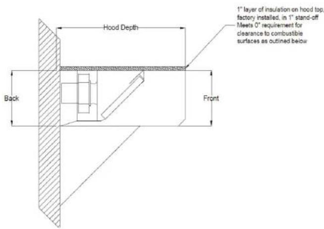
TOP COMBUSTIBLE CLEARANCE
text_image
Hood Depth 1" layer of insulation on hood top, factory installed, in 1" stand-off Meets 0" requirement for clearance to combustible surfaces as outlined below Back FrontEND COMBUSTIBLE CLEARANCE

text_image
Hood Length 1" layer of insulation on hood side, factory installed, inside 1" stand-off Meets 0" requirement for clearance to combustible surfaces as outlined belowFRONT AND REAR COMBUSTIBLE CLEARANCE

text_image
1" layer of insulation on hood rear, factory installed, in 1" stand-off Meets 0" requirement for clearance to combustible surfaces as outlined below Hood Depth Back Front Un-insulated front meets 0" requirement for clearance to combustible surfaces as outlined belowHalifaxHoods™
CLEARANCE REDUCTION METHODS:
Clearance reduction methods have been evaluated and tested and are certified by UL. The method of test was derived from UL 710 with temperature criteria taken from appropriate standards.
The hood may be installed with a 0" clearance to combustible materials per UL if constructed in one of the following manners:
- 1" thick min. layer of insulation of type Johns Manville 90005510, or similar insulation, or listed kitchen exhaust duct insulation.
- Cooking surface must not exceed temperatures above 600 degrees Fahrenheit.
- If the rear, top or sides of the hood are insulated, then it may be in contact with a combustible surface. The front of the hood does not require insulation to be in contact with a combustible surface.
- Hood surfaces which are perpendicular to the insulated surface do not need to be insulated in order to maintain the zero-clearance rating.
Wall or Single Island Canopy Hoods
HOOD INSTALLATION OVERVIEW
- When uncrating the hood please be careful not to bend or scratch the outer surface of the hood. Upon receiving your equipment, check for any interior or exterior damage. When the truck arrives at your location and the shipment is unloaded, it is YOUR responsibility to inspect each and every item for damage BEFORE signing the driver's delivery receipt/Bill of Lading. DO NOT sign until you have thoroughly looked over everything. Once you sign the delivery receipt/Bill of Lading, you relieve the trucking company and North American Kitchen Solutions, Inc. of any and all claims for damaged and/or missing items.
- If the hood is provided with filler panels, shipped loose, install them now.
- If the hood is provided with hood/duct sensors or thermostats, install them now.
- If the hood is provided with a back return plenum (BRP), install it now. See page 10, Installing the Back Return Plenum.
- If possible, connect ductwork to the hood before hanging or lifting into place, unless it prohibits the hood from being raised into place.
- At this point, drill holes in the building structural support system or utilize uni-strut to match up with the hanging bracket holes. Then slowly and evenly raise the hood into position and insert 1/2" diameter threaded rod (provided by others) between the hanger brackets and structure.
- If the hood was provided with any front or side ceiling supply plenums (other than the back-supply plenum), install these now. See page 10 for Installing Front/Side Ceiling Supply Plenums.
HalifaxHoods™
-
Install the remainder of both the exhaust and supply ductwork. For further guidelines see page 9, Installing Ductwork.
-
If the hood is provided with any backwall panels, install them now. See page 15, Installing Back wall Panels.
-
If the hood is provided with any side skirts, install them now. See page 16, Installing Side Curtains.
-
If the hood is a Type I hood, it will require a fire suppression system. Once the Type I hood(s) and ductwork are fully installed, equipment under hood is in place and walls are complete, the fire system should be completed. If the hood is provided with a factory-installed fire suppression system, the licensed and certified fire system installer should be contacted at this time to complete the final hookups, testing and system certification based upon manufacturer's specification and local fire codes.
-
If the hood is provided with a control package, it will need to be installed and wired by a licensed and certified electrician. This typically includes wiring the hood temperature sensors, hood lights and wiring the fire suppression micro-switches. If applicable, see wiring diagram provided with the control package.
-
If the hood is provided with enclosure panels, install them now. See page 17, Installing Enclosure Panels.
-
Install the rest of the hood accessories provided. This may include grease baffle filters or condensate mesh filters, grease cups, light bulbs (provided by others), light globes, and hem strips.
For questions regarding the supporting structure and its integrity, either the contractor or structural engineer must be consulted.
WARNING: NEVER PUNCTURE THE HOOD'S GREASE CONTAINMENT AREA TO HANG THE HOOD OR TO HANG ITEMS FROM THE HOOD. PUNCTURING THE GREASE CONTAINMENT AREA WILL VOID THE WARRANTY AND LISTING ON THE HOOD.
HalifaxHoods™
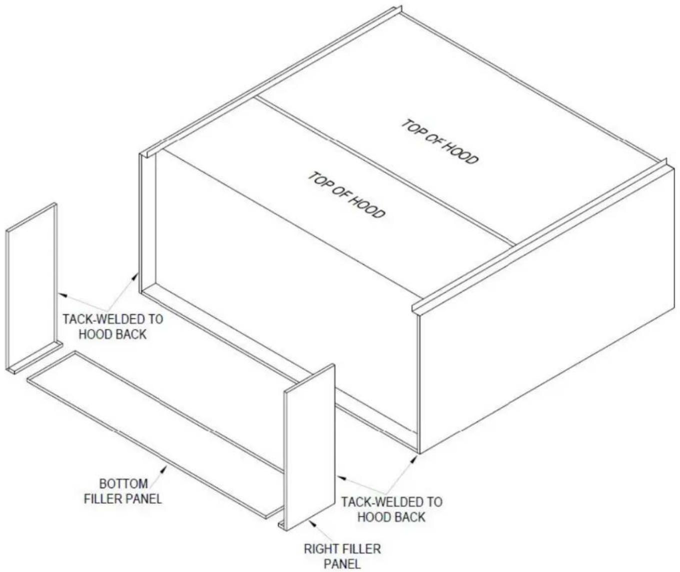
FILLER PANEL INSTALLATION
- Uncrate the hood and lay it on the floor with protective material between the hood and the floor.
- Position the filler panels to the back of the hood, and tack weld them into place.
- To allow for ease of cleaning, caulk the external seams with NSF Approved silicone caulk. Caulk
text_image
TOP OF HOOD TOP OF HOOD TACK-WELDED TO HOOD BACK BOTTOM FILLER PANEL TACK-WELDED TO HOOD BACK RIGHT FILLER PANELprovided by others.
HalifaxHoods™
DUCTWORK
Exhaust - As specified in NFPA 96, Ch. 7.5 (latest edition), exhaust duct systems must be constructed in the following manner:
Materials: Ducts shall be constructed of and supported by carbon steel not less than 1.37 mm (0.054 in.) (No. 16 MSG) in thickness, or stainless steel not less than 1.09 mm (0.043 in.) (No. 18 MSG) in thickness, UL listed Factory Made.
Installation: All seams, joints, penetrations, and duct to hood collar connections shall have a liquid-tight external weld. If you have an automatic fire damper, please refer to that manual for installation instructions now.
Supply - Supply ductwork (where applicable) should be connected to the hood in a manner approved by the local code authorities. If using prefabricated banded duct work, please refer to manufacturer's installation guide. It is recommended that a licensed HVAC installer or General Contractor completes the hood and ductwork installation.
HalifaxHoods™
Installing the Back Return Plenum
SUPPLY DUCTS
- Find the center of the back return plenum.
- If the back return plenum is to have one opening, cut the opening such that it is centered.
- The supply duct connection is tack-welded at 1" to 2" intervals or sheet metal screws at 3" to 6" spacing to the hood.
- When the back return plenums are insulated, the edges of the insulation must be taped after the hole is cut. (The insulation tape is provided by others).
HANGING THE PLENUM
- The back return plenum needs to be mounted 18" to 26" above the finished floor. This is measured from the lowest rear edge of the back supply plenum to the finished floor.
- Fasten the back of the plenum to the wall, going through the lower portion of the plenum back supply wall.
a. These fasteners supplied by others are to help maintain the location of the back supply and are intended to hold the weight of the back supply unit.
b. The fasteners should not interfere with the air diffusers.
INSTALLING FRONT AND SIDE PLENUM
Hanger Bracket and Threaded Rod Installation
- Insert 3/8" diameter threaded rod (supplied by others) into hanger brackets on the ceiling supply plenum top. Raise and hang the ceiling supply plenum from adequate roof or ceiling supports.
- The ceiling supply plenum should be resting lightly against the hood. The hood is only used to position
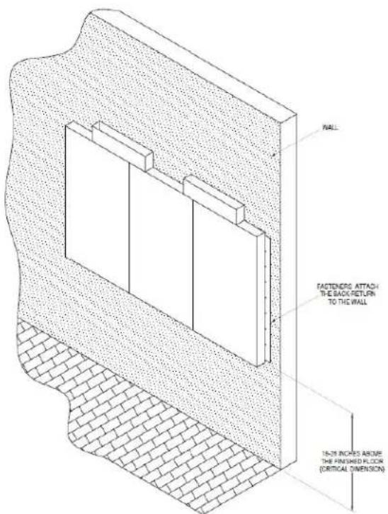
text_image
WALL FASTENERS ATTACH THE BACK-RETURN TO THE WALL 16-inch INCHES ABOVE THE FINISHED FLOOR (CRTICAL DIMENSION)HalifaxHoods™
the plenum; it is not intended to support the plenum. All hanger brackets on the ceiling supply plenum must be used and the plenum must be properly supported while lifting to prevent damage or distortion. The ceiling supply plenum must be level to operate properly.
- It is recommended that caulk be applied at the mating seams and surfaces of the ceiling supply plenum, the hood, and the wall. If the ceiling supply plenum is next to a wall, you will need to caulk around the surface next to the wall. Caulk the joints with NSF Approved silicone caulk. Caulk is provided by others.
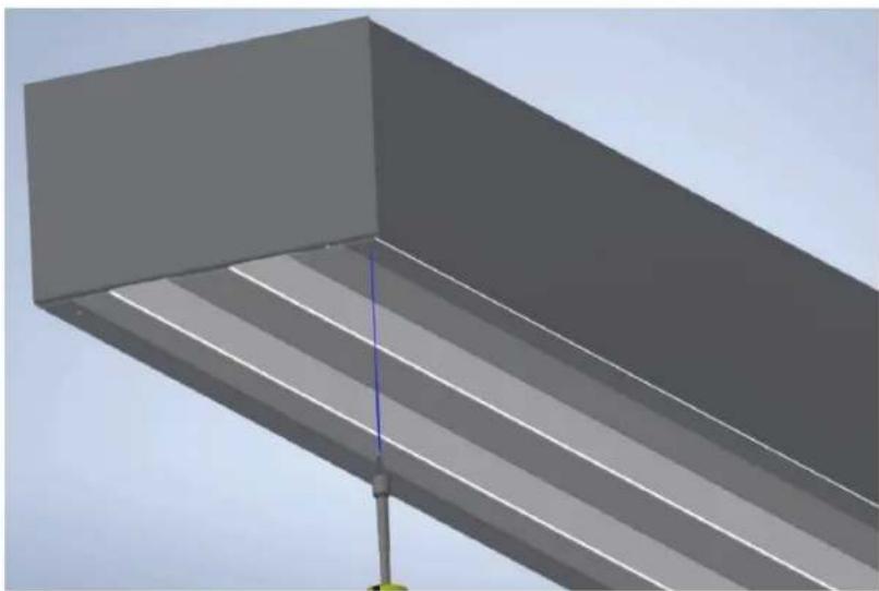
UNI-STRUT INSTALLATION
The uni-strut (supplied by others) supporting the hood may be cantilevered over the end of the hood. Utilizing the ceiling supply plenum's hanger brackets, securely fasten to the uni-strut.

text_image
THREADED ROD SUPPLIED BY OTHERS UNI-STRUT (U-CHANNEL) SUPPLIED BY OTHERS HOOD END VIEW CEILING PLENUMHalifaxHoods™
PERFORATED SUPPLY PLENUM (PSP) SCREEN REMOVAL
Tools needed - 5/16" Nut Driver and proper Gloves to protect against metal edges
- Use 5/16" nut driver to remove #8 hex head screws from PSP Screen.
natural_image
3D rendering of a gray structural beam with diagonal white stripes against a clear sky (no text or symbols)- Push the screen away from the screw location to 'unlock' the screen.

natural_image
3D diagram of a vehicle or road with a red arrow indicating direction, no text or symbols presentHalifaxHoods™
- Push up on PSP Screen and this will allow it to drop out easily (be cautious to avoid damage to PSP and Screen).

natural_image
3D rendering of a structural beam with diagonal white stripes and a blue curved arrow indicating rotation (no text or symbols)- PSP Screen is now free to be removed. Repeat if PSP Screen is in two (2) pieces.

natural_image
3D diagram of a structural beam with two red arrows indicating downward forces or points, no text or symbols present.Installation is reverse of removal.
HalifaxHoods™
Electrical Connections
HOOD LIGHTS
If the hood is provided with lights, a junction box will be located on top of the hood for field connections. Use minimum 14 AWG copper wire. Light bulbs will not be provided. For incandescent fixtures, standard light bulbs up to 100 watts may be used.
For multiple hood systems that have more than 14 lights total, the hood lights must be wired to multiple circuits. Each circuit must have less than 14 lights total.
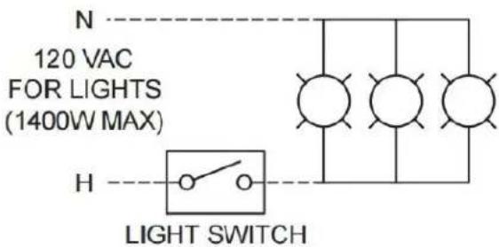
text_image
N 120 VAC FOR LIGHTS (1400W MAX) H LIGHT SWITCHHalifaxHoods™
INSTALLING BACKWALL PANEL
- After hood is hung into position, slide the top of the backwall panel behind the back of the hood. If the hood is provided with flat backwall panels, seam strips will be provided. Install seam strips between panels as shown in the flat backsplash panel section view.
- After the backwall panel and seam strips have been positioned, drill holes in the panel and fasten to the wall.
- Caulk the joints between the hood and the backsplash panel with NSF Approved silicone caulk. Caulk provided by others.

text_image
Flat Backwall PanelBackwall Panel Installation
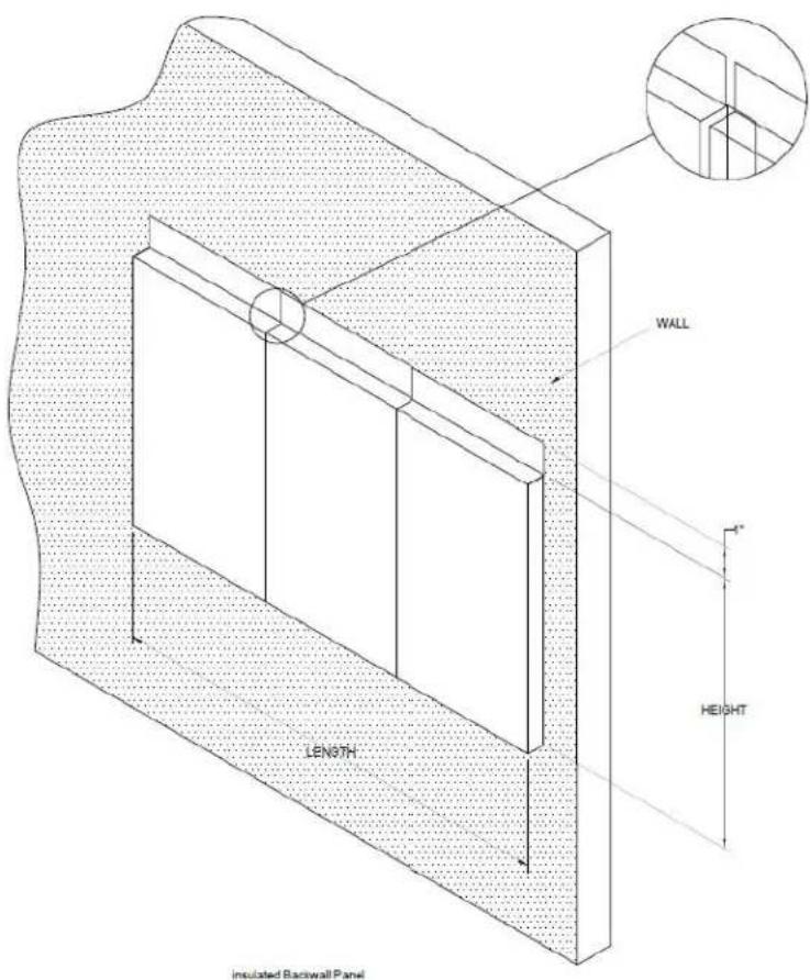
text_image
WALL LENGTH HEIGHT insulated Backwall PanelInsulated Backwall Panel
HalifaxHoods™
INSTALLING SIDE CURTAIN
-
After the hood is hung in position, line up the top of each side curtain with the side of the hood.
-
Adjust side curtain to line up with back of the hood.
-
Install trim strip where the side curtain meets the side of the hood
-
Caulk the joints between the hood and the side curtain with NSF Approved silicone caulk. Caulk provided by others.

text_image
FULL SIDE PANEL ATTACH TO WALL FASTENERS BY OTHERS -HOLE DRILLED BY INSTALLER -1/4" BOLT & CAP NUT (SUPPLIED BY OTHERS) FULL SIDE PANELHalifaxHoods™
INSTALLING CEILING ENCLOSURE PANELS
Prior to the installation of Ceiling Enclosure Panels, be sure that all ductwork, fire, and electrical connections have been made.
- Position the end enclosure panels on the hood, and clamp into place clamps provided by others and then tack-weld the panels into place.
- Fasten the end enclosure panels to the wall (fasteners provided by others).
a. If the hoods are mounted back-to-back (Island type), panels to be bolted to each other (fasteners provided by others). - Fasten enclosure panels.
- To allow for ease of cleaning, caulk the external seams with NSF Approved silicone caulk. The caulk is not provided.
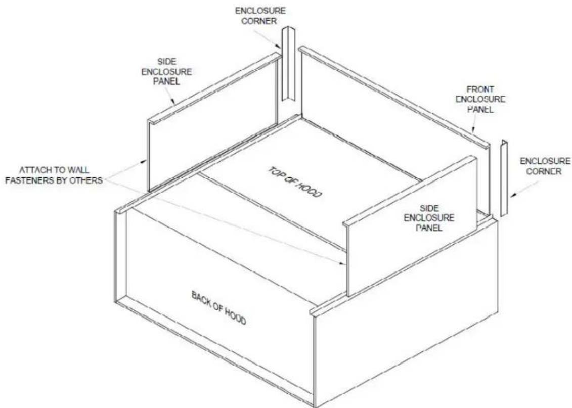
text_image
ENCLOSURE CORNER SIDE ENCLOSURE PANEL ATTACH TO WALL FASTENERS BY OTHERS TOP OF HOOD BACK OF HOOD FRONT ENCLOSURE PANEL SIDE ENCLOSURE PANEL ENCLOSURE CORNERCEILING CLOSURE INSTALLATION
HalifaxHoods™
Operation
Prior to starting up units, the following items must be verified:
- Both Exhaust and Supply fans must be wired correctly and rotation must be verified. Direction can be confirmed by observation of the arrows stamped on them.
- All filters must be in place with no gaps
- All Equipment located under the hood is in place and functioning.
- HVAC systems are in place and operating as per manufacturer's recommendations.
Commercial kitchen ventilation hoods are intended to be used with ductwork and fans which have been properly sized and properly installed in accordance with manufacturer's specifications and local code requirements. NOTE: Use Licensed HVAC or General Contractor recommended.
Before turning on cooking equipment, make sure that the make-up air and exhaust fans are on. Leave fans on for at least 30 minutes after cooking equipment is shut off.
Clean hood as needed to comply with local code requirements and as directed in the Maintenance section of this manual.
GUIDELINES BEFORE START-UP
When referencing the airflow rates in UL file, please note:
a) The exhaust and supply (when provided) air flow rates were established under controlled laboratory conditions.
b) Greater exhaust and/or lesser supply air (when provided) is required for complete vapor and smoke removal in specific installations.
Performing a test and balance of a system is needed to ensure proper and efficient operation of the system. Whenever there is effluent and hot air removed, a large amount of air must be replaced to balance the space. Any change in the pressure differential between inside and outside air will affect the operation of a system.
A test and balance report, as well as the simple performance test in International Mechanical Code Section 507.16.1, should be included in all jobs; code inspectors are increasingly enforcing these requirements. Requirements in the 2006 IMC, which is currently effective in most parts of the United States, are as follows:
"507.16 Performance test. A performance test shall be conducted upon completion and before final approval of the installation of a ventilation system serving commercial cooking appliances. The test shall verify the rate of exhaust airflow required by Section 507.13, makeup airflow required by Section 508, and proper operation as specified in this chapter. The permit holder shall furnish the necessary test equipment and devices required
HalifaxHoods™
to perform the tests.
507.16.1 Capture and containment test. The permit holder shall verify capture and containment performance of the exhaust system. This field test shall be conducted with all appliances under the hood at operating temperatures, with all sources of outdoor air providing makeup air for the hood operating and with all sources of recirculated air providing conditioning for the space in which the hood is operating. Capture and containment shall be verified visually by observing smoke or steam produced by actual or simulated cooking, such as with smoke candles, smoke puffers, etc."
Before initial operation of the blower, tighten set screws according to the procedure outlined below.
PROCEDURE FOR TIGHTENING SET SCREWS IN HUBS AND FINGER GUARD.
Using a torque wrench, tighten the set screw to the torque recommended in Table 1.
- Using a torque wrench, tighten one set screw to half of the torque recommended in Table 1.
- Tighten the second set screw to the full recommended torque.
- Tighten the first set screw to the full recommended torque.
Table 1. Recommended Tightening Torque for Set Screws
| Set Screw Diameter Torque (in-lbs) | |
| #10 35 | |
| 1/4 80 | |
| 5/16 126 | |
| 3/8 240 | |
| 7/16 384 | |
| 1/2 744 | |
| 9/16 1080 | |
| 5/8 1500 | |
| 3/4 2580 | |
| 7/8 3600 | |
| 1 5400 | |
HalifaxHoods™
Troubleshooting Guide
| Problem: Smoke blows away before reaching the bottom of the hood. | |
| Are there pass-thru windows near the hood? Adjust amount and locations of make-up air to eliminate drafts through the pass-thru windows. | |
| Is the make-up air part of the hood or an attached plenum? | Try turning off or reducing the amount of make-up air; block off portions of the supply to direct air away from the problem area (test with card-board). |
| Problem: Pilot lights are being blown out or cooking equipment is being cooled by make-up air. | |
| Are there drafts from make-up air? Try turning off or reducing the amount of make-up air; block off portions of the supply to direct air away from the problem area (test with card-board first); remove any obstructions in front of supply that directs air toward cooking equipment. | |
| Problem: Cold air can be felt by the cook at the hood. | |
| Is this a short circuit hood? Turn off or reduce the amount of air supplied to short circuit. | |
| Is the make-up air part of the hood or an attached plenum? | Try turning off or reducing the amount of make-up air; cool the supply air. |
| Problem: Cooking odors in the dining area. | |
| Is the hood capturing? Hood is not drawing enough air, see sections above on hood capture. | |
| Is there a draft through doors between the kitchen and dining area? | Decrease make-up air in the kitchen; increase exhaust air through hood. |
| Problem: Grease is running off the hood. | |
| Is there grease on top of the hood? Exhaust duct is not correctly welded. | |
| Is the caulk missing or damaged? Clean problem area and re-caulk.Is the grease cup inserted properly? Put grease cup back in place. | |
| Problem: Hood is noisy. | |
| Is the blower running in the correct direction? Check rotation and reverse voltage if appropriate. | |
| Are the filters in place? Replace missing filters.Is the hood over exhausting? Slow down blower with use of a Solid State Speed Controller. |
HalifaxHoods™
ITEMS THAT MAY AFFECT HOOD PERFORMANCE
- HVAC units are to supply outside air (OA) to the room to balance the system. If HVAC units are not supplying the proper amount of OA to the building, then negative pressure will exist and the HVAC unit's economizers must be adjusted.
- HVAC return grilles located very close to a hood can cause performance problems. The return grille competes with the hood to capture air in the room. If a return air grille is located within six feet (6') of the hood, it can have a serious effect on the hood's ability to capture.
- HVAC diffusers located very close to a hood also can affect the capture ability of the hood. When the air from the HVAC diffuser deflects off of the front of the hood, or along the hood, the air flow created can draw smoke and contaminants out of the hood.
Before calling your representative to report a problem, have the following information available:
-
Review / summary of troubleshooting section on (page 20) installation operation manual.
-
Hood model and serial number.
-
Current cooking equipment line-up.
-
Size of hood (length, width, and height).
-
Island or wall configuration.
-
Nature of spillage (one end; all around the edges).
-
Does the smoke make it to the hood?
-
Height hood is mounted above finished floor.
-
How make-up air is brought into the kitchen (hood, ceiling diffusers, separate plenum).
-
Is the hood system controlled by an automated system or VFD?
-
Is the blower making any unusual noise?
HalifaxHoods™
Recommended Guidelines for Maintaining Your Hood System
According to NFPA, dirty hoods are the major cause of fire in commercial kitchens. Following these simple recommended guidelines can prevent that from happening.
HOOD - DAILY (RECOMMENDED)
☐ Inspect grease filters checking for accumulated grease, clean if necessary (instructions stated below).
☐ Remove grease cup, empty contents and clean using mild detergent or degreaser if necessary.
☐ Wipe interior of hood to remove accumulated grease and debris using mild detergent if necessary. Do not use abrasive cleaners such as powdered cleaners, or abrasive cleaning cloths.
□ Wipe globes on lights.
HOOD - WEEKLY (RECOMMENDED)
☐ Remove baffle grease filters and wash in dishwasher or sink with mild detergent.
If application is in a heavy grease-producing environment, more frequent cleaning may be required.
□ Clean entire interior of the hood prior to replacing baffle filters. Use mild detergent if necessary; do not use abrasive cleaners or cloths.
HalifaxHoods™
We suggest having a certified hood cleaning company inspect and professionally clean your hood system. Below are the recommended guidelines based on use.
☐ Hoods over non-grease applications/low volume cooking – 1-year cleaning requirement
☐ Pizza restaurants and oven hoods - 180-day cleaning requirement
☐ Typical restaurants, cafeterias, and hotel or hospital kitchens – 90-day requirement
☐ Hamburger and fast food restaurants, wood-burning or charcoal-burning stoves, restaurants open 24 hours – 30-day cleaning requirement
EXHAUST BLOWER - MONTHLY (RECOMMENDED)
☐ After 100 operating hours or one month, whichever comes first, tighten set screws to the full recommended torque found in Table 1.
☐ Check breather tube cover to ensure it is free of debris.
□ Clean exhaust blower wheel and inside of housing. Heavy grease buildup can be a fire hazard and can also cause exhaust wheel to become unbalanced, a condition that will result in premature bearing wear.
WARNING
Even when the power supply is locked out, blower may cause injury or damage if the impeller is subject to "wind-milling" which is the turning of the impeller and drive components due to a draft in the system. To guard against this hazard, the impeller should be secured to physically restrict rotational movement.
LIMITED WARRANTY
WARRANTY AND DISCLAIMER
This limited warranty extends only to the original purchaser with proof of purchase. North American Kitchen Solutions warrants that Halifax Hoods Products shall be free from original defects in workmanship and materials for two years from date of shipment provided the Products have been properly handled, stored, installed, serviced, maintained, and operated. This warranty shall not apply to Products which have been altered or repaired without North American Kitchen Solutions' express authorization, or altered or repaired in any way so as, in North American Kitchen Solutions' judgment, to affect performance or reliability, nor which have been improperly installed or subjected to misuse, negligence, accident, or incorrectly used in combination with other substances. Wear items, such as V-Belts, filters, etc. are not included as covered parts under this Warranty.
Reimbursement for labor for removing and/or re-installing replacement parts is included in this Warranty for a period of 30 days from field start-up or 90 days from the date of Shipment, whichever comes first. NAKS, Inc. is responsible to determine the amount of labor reimbursement allowed based upon the circumstances for each installation. Labor cost reimbursement must be approved by NAKS in writing prior to the work being performed. You assume all risks and liability for results of use of all Products.
LIMITATION OF REMEDY AND DAMAGES
All claims under this warranty must be made in writing and delivered by U.S. Mail to:
North American Kitchen Solutions, Inc.
172 Reaser Court
Elyria, OH 44035
Attn: WARRANTY CLAIMS DEPARTMENT
All Product claims must be made within 15 days after discovery of the defect and prior to the expiration of two years from the date of shipment. Claims made beyond that period are barred. Within 30 days after receipt of a timely claim, North American Kitchen Solutions shall have the option either to inspect the Product at its location or request its return to North American Kitchen Solutions at your expense. North American Kitchen Solutions shall replace, or at its option, repair, free of charge, any Product it determines to be defective, and it shall ship the repaired or replacement product to you F.O.B. point of shipment; provided, however, if in North American Kitchen Solutions' judgment circumstances are such to prohibit repair or replacement to remedy the warranted defects, your sole and exclusive remedy shall be a refund of any part of the invoice price, paid to North American Kitchen Solutions, for the defective Product or part.
HalifaxHoods™
North American Kitchen Solutions is not responsible for the cost of removal of the defective Product or part, damages due to removal, or any expenses incurred in shipping the Product, or the installation of the repaired or replaced Product or part.
The warranties set forth above do not apply to any components, accessories, parts, or attachments manufactured by other manufacturers; such being subject to the manufacturer's warranty, if any. To the extent not prohibited by the manufacturer's warranty, North American Kitchen Solutions shall pass to you such manufacturer's warranty.
THIS WARRANTY IS IN LIEU OF ALL OTHER WARRANTIES, EXPRESS OR IMPLIED, ARISING BY LAW OR OTHERWISE, INCLUDING WITHOUT LIMITATION THE IMPLIED WARRANTIES OF MERCHANTABILITY AND FITNESS FOR A PARTICULAR PURPOSE, WHICH ARE HEREBY EXPRESSLY DISCLAIMED AND WAIVED. THIS WARRANTY CONSTITUTES NORTH AMERICAN KITCHEN SOLUTIONS' SOLE AND EXCLUSIVE WARRANTY FOR DEFECTIVE GOODS AND PURCHASER'S SOLE AND EXCLUSIVE REMEDY FOR DEFECTIVE PRODUCTS.
No employee, agent, dealer, or other person is authorized to give any warranties on behalf of North American Kitchen Solutions or to assume for it any other liability in connection with any of its products except in writing and signed by an officer of North American Kitchen Solutions.
LIMITATION OF LIABILITY
Halifax Hoods and its affiliates' cumulative liability to you and any other persons for all claims in any way relating to or arising out of the Products, including, but not limited to, any cause of action sounding in contract, tort, or strict liability, shall not exceed the total amount of the purchase price paid for those Products which are the subject of any such claim. This limitation of liability is intended to apply without regard to whether other provisions of this agreement have been breached or have proven ineffective even if Halifax and its affiliates has been advised of the possibility of such claims or demands. In no event shall Halifax and its affiliates be liable to you or any other person for any loss of profits or any incidental, special, exemplary, or consequential damages for any claims or demands brought by you or such other persons. BECAUSE SOME JURISDICTIONS DO NOT ALLOW THE EXCLUSION OR LIMITATION OF LIABILITY FOR CONSEQUENTIAL OR INCIDENTAL DAMAGES, THIS LIMITATION MAY NOT APPLY TO YOU.
Halifax and its affiliates' maximum liability to you and to any end user is as set forth above. North American Kitchen Solutions makes no warranty to anyone for any products not manufactured by it and shall have no liability for any use or installation of any products (whether manufactured by North American Kitchen Solutions or other manufacturers) not specifically authorized by this sale. You acknowledge various warnings by North American Kitchen Solutions regarding the Products and its installation and use. If North American Kitchen Solutions incurs any claims, lawsuits, settlements, or expenses (including attorney fees) for any loss, injury, death or property damage including, but not limited to, claims arising out of your or any end user's installation or use of the Products, you agree to indemnify and hold Halifax and its affiliates harmless.
HalifaxHoods™
REPLACEMENT PARTS
If replacement parts are ordered, purchaser warrants that the original components in which these replacement parts will be placed are in satisfactory working condition, and when said replacement parts are installed, the resultant installation will operate in a safe manner, at speeds and temperatures for which the original product was purchased.
TECHNICAL ADVICE AND RECOMMENDATIONS, DISCLAIMER
Notwithstanding any past practice or dealings or any custom of the trade, sales shall not include the furnishing of technical advice or assistance or system design. Any such assistance shall be at Halifax and its affiliates sole option and may be subject to additional charge(s).
Halifax and its affiliates assume no obligation or liability on account of any recommendations, opinions, or advice as to the choice, installation or use of Products. Any such recommendations, opinions, or advice are given and shall be accepted at your and the end-user's risk and shall not constitute any warranty or guarantee of such Products or their performance.