Smart App Online OL10KRTMBTF - Inverter CyberPower - Free user manual and instructions
Find the device manual for free Smart App Online OL10KRTMBTF CyberPower in PDF.

User questions about Smart App Online OL10KRTMBTF CyberPower
0 question about this device. Answer the ones you know or ask your own.
Ask a new question about this device
Download the instructions for your Inverter in PDF format for free! Find your manual Smart App Online OL10KRTMBTF - CyberPower and take your electronic device back in hand. On this page are published all the documents necessary for the use of your device. Smart App Online OL10KRTMBTF by CyberPower.
USER MANUAL Smart App Online OL10KRTMBTF CyberPower
OL6KRTHW | OL8KRTHW | OL10KRTHW

natural_image
Illustration of a server rack with front panel and control panel (no text or symbols)SAVE THESE INSTRUCTIONS
Please read this manual and follow the instructions for installation and operation.
SAFETY INSTRUCTIONS
SAVE THESE INSTRUCTIONS
This manual contains important instructions that should be followed during installation and maintenance of the UPS and batteries.
The SmartApp Online 6-10kVA UPS models that are covered in this manual are intended for installation in an environment within 32°F to 104°F (0°C to 40°C), free of conductive contaminants.
SPECIAL SYMBOLS

Warning: High voltage - Risk of Electric Shock

Caution - Important Instructions: must always be followed.

Do Not Discard: the UPS or UPS batteries in trash. The batteries contain lead acid. For more information, contact your local recycling or hazardous waste facility.

Information, advice, help

See applicable user manual
SAFETY INSTRUCTIONS CONT.
PERSONAL SAFETY
CAUTION

To reduce the risk of fire, connect the UPS to a branch circuit with 40 amperes (6,000 VA)/50 amperes (8,000 VA)/70 amperes (10,000 VA) maximum over-current protection in accordance with the National Electric Code, ANSI/NFPA 70.
The AC electrical service where the UPS is connected should be close to the unit and easily accessible.
Please use only UL-marked mains cable, (e.g. the mains cable of your equipment), to connect the UPS to the AC outlet.
Please use only UL-marked power cables to connect any equipment to the UPS.
When installing the equipment, ensure that the sum of the leakage current of the UPS and the connected equipment does not exceed 3.5mA.
Do not unplug the unit from AC power during operation, as this will disconnect the protective ground insulation.
Do not use an improper size power cord as it may cause damage to your equipment and cause fire hazards.
Make sure everything is turned off and disconnected completely before conducting any maintenance, repairs or shipment.
DO NOT INSTALL THE UPS WHERE IT WOULD BE EXPOSED TO DIRECT SUNLIGHT OR NEAR A STRONG HEAT SOURCE!
DO NOT CONNECT DOMESTIC APPLIANCES SUCH AS HAIR DRYERS TO UPS OUTPUT SOCKETS!
SERVICING OF BATTERIES SHOULD BE PERFORMED OR SUPERVISED BY PERSONNEL KNOWLEDGE OF BATTERIES AND THE REQUIRED PRECAUTIONS. KEEP UNAUTHORIZED PERSONNEL AWAY FROM BATTERIES!
FOR PERMANENTLY CONNECTED EQUIPMENT, A READILY ACCESSIBLE DISCONNECT DEVICE SHALL BE INCORPORATED IN THE BUILDING INSTALLATION WIRING.
RISK OF ELECTRIC SHOCK

A battery can present a risk of electric shock and high short circuit current. The following precaution should be observed when working on batteries:
Remove watches, rings or other metal objects.
Use tools with insulated handles.
The UPS must be connected to a grounded AC power outlet with fuse or circuit breaker protection. DO NOT plug the UPS into an outlet that is not grounded. If you need to power-drain this equipment, turn off and unplug the unit.
SAFETY INSTRUCTIONS CONT.
PERSONAL SAFETY CONT.
RISK OF ELECTRIC SHOCK CONT.

(No User Serviceable Parts): Risk of electric shock, do not remove cover. No user serviceable parts inside. Refer servicing to qualified service personnel.
To prevent the risk of fire or electric shock, install in a temperature and humidity controlled indoor area, free of conductive contaminants. (Please see specifications for acceptable temperature and humidity range).
To avoid electric shock, turn off and unplug the unit before installing the input/output power cord with a ground wire. Connect the ground wire prior to connecting the line wires!
Connect the Protection Earth (PE) safety conductor before any other cables are connected.
(Fuses): To reduce the risk of fire, replace only with the same type and rating of fuse.
PRODUCT SAFETY
RISK OF ELECTRIC SHOCK

The battery can power hazardous components inside the unit, even when the AC input power is disconnected.
The UPS should be placed near the connected equipment and easily accessible.
(Non-Isolated Battery Supply): Risk of electric shock, battery circuit is not isolated from AC power source; hazardous voltage may exist between battery terminals and ground. Test before touching.
All UPS models covered in this document are permanently-connected equipment and only qualified maintenance personnel may carry out installations.
Wiring must be done by qualified personnel.
DO NOT USE FOR MEDICAL OR LIFE SUPPORT EQUIPMENT! Under no circumstances should this unit be used for medical applications involving life support equipment and/or patient care.
DO NOT USE WITH OR NEAR AQUARIUMS! To reduce the risk of fire, do not use with or near aquariums. Condensation from the aquarium can come in contact with metal electrical contacts and cause equipment to short out.
The unit has a dangerous amount of voltage. When the UPS indicators is on, the units may continue to supply power thus the unit's outlets may have a dangerous amount of voltage even when it's not plugged in to the wall outlet.
SAFETY INSTRUCTIONS CONT.
PRODUCT SAFETY CONT.
BATTERY

Do not dispose of batteries in fire as the battery may explode.
Do not open or mutilate the battery, released electrolyte is harmful to the skin and eyes.
TABLE OF CONTENTS
SAFETY INSTRUCTIONS ......II
Special Symbols....II
Personal Safety....III
Product Safety IV
INTRODUCTION ....1
Smart App Online UPS Systems....1
UPS Extended Battery Modules....1
Step-Down Transformer....1
Unpacking Procedures....2
Whats In The Box....3
OVERVIEW....4
Power Module....4
Maintenance Bypass Module....5
INSTALLING YOUR UPS SYSTEM 7
System Block Diagram....7
Hardware Installation Guide....7
HARDWARE INSTALLATION 9
Rackmount Installation 9
Vertical/Tower Installation....11
MAINTENANCE BYPASS MODULE INSTALLATION ....12
Electrical Installation....13
Input/Output Configuration....14
Backfeed Protection Operation....14
Without Backfeed Protection Configuration....15
With Backfeed Protection Configuration....15
EXTENDED BATTERY MODULE INSTALL....16
Rear Panel Description....16
Connection With Power Module....16
OPTIONAL LCD CONTROL PANEL INSTALLATION....19
Remote Control....19
Wall-mounting Instructions....19
UPS SYSTEM STARTUP....20
USING THE UPS SYSTEM ......21
LCD Module....21
LCD Menu Tree....22
MAINTENANCE 31
Battery Replacement....31
Manual Bypass Switch Operation....31
TECHNICAL SPECIFICATIONS....33
TROUBLESHOOTING....38
PRODUCT REGISTRATION....38
LIMITED WARRANTY AND CONNECTED EQUIPMENT GUARANTEE....40
CONFORMANCE APPROVAL....44
INTRODUCTION
CyberPower Smart App Online rack/tower UPS systems, with double-conversion topology, provide sine wave output to mission-critical applications and equipment requiring seamless power correction. These units offer generator compatibility and deliver clean AC power with zero transfer time.
They offer Smart Battery Management (SBM), which helps extend overall battery life, and Fast Charge Technology, which helps keep recharge times less than five hours, regardless of the number of Extended Battery Modules (EBMs). Features include a rotatable LCD control panel, energy-saving GreenPower UPS™ ECO Mode technology, and PowerPanel® Business Edition software for controlling and managing the UPS. Smart App Online UPS systems come with a three-year warranty and a \$300,000 Connected Equipment Guarantee.
UPS EXTENDED BATTERY MODULES
Extended Battery Modules (EBMs) from CyberPower increase battery runtimes during power outages. Each rack/tower convertible EBM uses 3U of rack space, depending upon the model, and can be installed in a tower form factor to match the UPS installation. The DC plug-and-play power connectors allow for daisy-chaining additional EBMs to a UPS system. EBMs compatible with Smart App Online UPS systems also have a built-in battery charger, providing Fast Charge Technology to quickly restore the backup power supply. Every CyberPower EBM has a three-year warranty.
STEP-DOWN TRANSFORMER
CyberPower Step-Down and Isolation Transformers (OL6KSTF/OL10KSTF) are designed for a variety of CyberPower UPS systems. When combined with the UPS systems, the Step-down transformer converts voltage from 200-240V down to 100-120V.
INTRODUCTION CONT.
UNPACKING PROCEDURES

Information, advice, help
The unit is very heavy, please handle with care. Wear safety shoes and use hydraulic equipment lift if one is available. At least two people are required for all handling operations, including unpacking, lifting, and installation in rack system. Do not use the lifting straps to carry the unit around; they are provided for manually unpacking the unit from the carton only.
USE LIFTING STRAPS TO REMOVE UNIT FROM THE BOX.
natural_image
Architectural line drawing of a building interior with open and closed views (no text or symbols)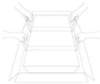
natural_image
Line drawing of two hands holding a rectangular object, no text or symbols present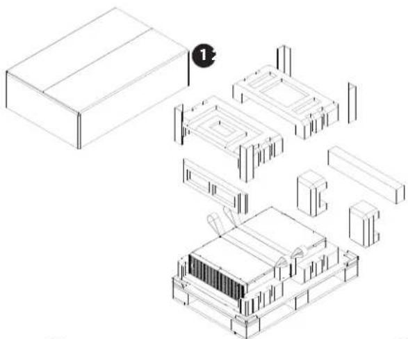
natural_image
Isometric line drawing of a modular electronic or mechanical assembly with no visible text or symbols
natural_image
Isometric line drawing of a building with structural elements and a circular element above (no text or symbols)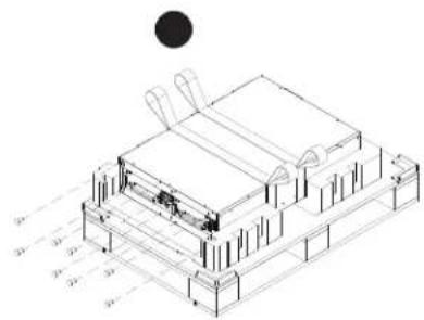
text_image
Technical diagram of a layered electronic device with labeled components and dimensions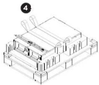
natural_image
Isometric line drawing of a building structure with no visible text or symbols
natural_image
Isometric line drawing of a multi-level electronic device or enclosure with internal components and a black circular element (no text or symbols)
natural_image
Technical line drawing of a multi-layered electronic device housing with internal components and mounting brackets (no text or symbols)INTRODUCTION CONT.
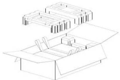
WHATS IN THE BOX
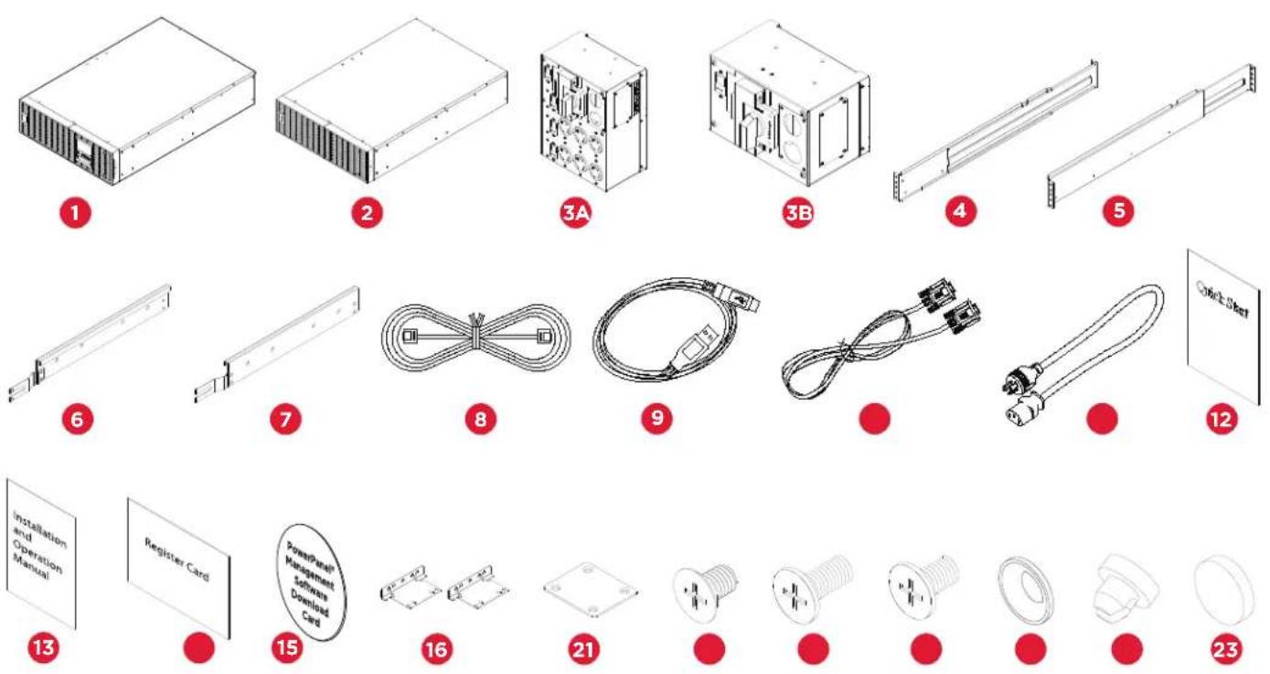
| ITEM | CONTENT | QTY |
| 1 Power module 1 | ||
| 2 Extended Battery Module (EBM) | 1 | |
| 3A | 6U Maintenance Bypass Switch Module for OL6KRTMB, OL8KRTMB and OL10KRTMB models | 1 |
| 3B | 3U Maintenance Bypass Switch Module for OL6KRTHW, OL8KRTHW and OL10KRTHW models | |
| 4 | Rackmount left rail | 2 |
| 5 | Rackmount right rail | 2 |
| 6 | Left hanging bracket | 2 |
| 7 Right hanging bracket | 2 | |
| 8 | Phone line | 1 |
| 9 | USB communication cable | 1 |
| 10 | Serial Interface Cable (RS-232) | 1 |
| ITEM | CONTENT | QTY |
| 11 | NEMA L6-30R to IEC-320-C13 power cord | 1 |
| 12 | Quick Start Guide | 1 |
| 13 | Installation and Operation Manual | 1 |
| 14 | Registration warranty card | 1 |
| 15 | PowerPanel Management software download card | 1 |
| 16 | Rackmount ears | 4 |
| 17 | Tie plate | 1 |
| 18 | Flat head screws M5X7L | 16 |
| 19 | Pan head screws M5X12L | 24 |
| 20 | Pan head screws M5X6L | 12 |
| 21 | Plastic washers | 16 |
| 22 | Screw hole dust covers | 28 |
| 23 | Rubber pads | 24 |
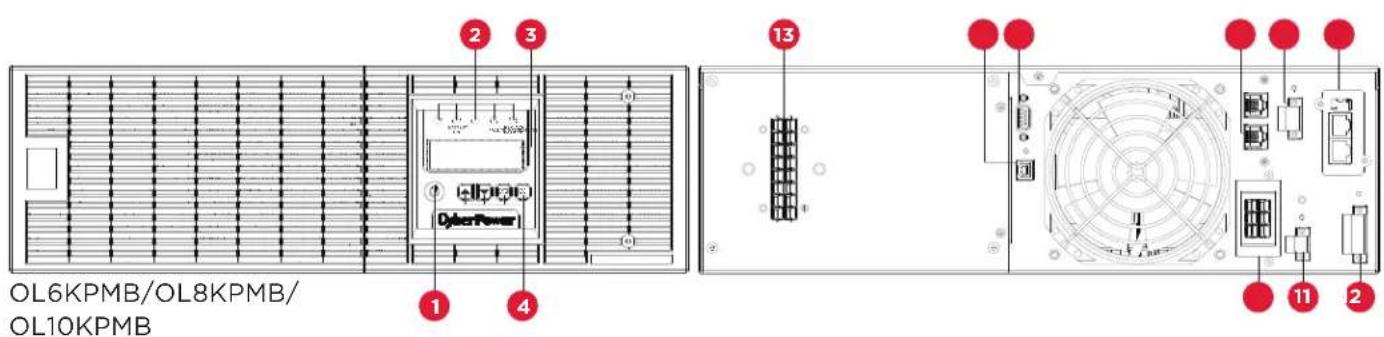
OVERVIEW
POWER MODULE
text_image
OL6KPMB/OL8KPMB/ OL10KPMB1. Power Button / Power on Indicator
Master ON/OFF for the UPS. Indicates that the UPS is on and supplying power.
2. UPS Status / Fault / Replace Battery LED Indicator
Indicates the status of the UPS whether is operating in Line, Battery or Bypass Mode, or the UPS has an internal fault or the battery needs to be replaced.
3. Multifunction LCD Readout
Shows UPS status, information, settings and events.
4. Function Buttons
Scroll up, scroll down, Enter and Escape.
5. USB port
This is a connectivity port which allows communication and control between the UPS and the connected computer. It is recommended to install the PowerPanel® Business Edition Agent software on the PC/Server connected with the USB cable.
6. Serial Port
Serial port provides communication between the UPS and the computer. The UPS can control the computer's shutdown during a power outage through the connection while the computer can monitor the UPS and alter its various programmable parameters.
7. Surge Protected Communication Ports RJ-45/RJ-11
These ports are used to protect standard RJ-45/RJ-11 based products (ADSL, LAN, Phone/ Modem-Lines) and cabling systems from surges.
8. Relay Output Connector
Convert UPS signals into relay potential-free Dry Contacts for industrial control.
9. Expansion slot
Remote management card is pre-installed in expansion slot.
10. Backfeed Protection Connector
Prevents power feedback from the inverter to utility power in case of power failure and a fault in the bypass circuit.
OVERVIEW CONT.
POWER MODULE CONT.
- EPO (Emergency Power Off) Connector
Enables an emergency UPS power-off from a remote location.
- Extended Battery Module Connector
Connection for additional CyberPower Extended Battery Modules (EBM).
- Input / Output Connectors
Use these connectors to attach the Maintenance Bypass Module to the power module.
MAINTENANCE BYPASS MODULE

OVERVIEW CONT.
1. Input Circuit Breaker
Provides input overload and fault protection.
2. Manual Bypass Switch
Provides UPS output to connected equipment when turned to Normal. Provides utility power to connected equipment when turned to Bypass.
3. Input / Output Terminal Block
Connect to utility power/equipment load.
4. Interlock Bracket
Safety bracket to prevent accidental operation of maintenance bypass switch.
5. Inspection Window
Remove the cover to visually inspect wiring is secure and connected to the proper terminal position.
6. Input/Output Connector
Use these connectors to attach the Maintenance Bypass Module to the power module.
7. Connector Cover
Provides safety protection when removing the Maintenance Bypass Module.
8. Output Circuit Breaker
Provides output overload and fault protection.
9. Battery Backup & Surge Protected Outlets
Provides battery backup and surge protection. They ensure power is provided to connected equipment over a period of time during a power failure.
Critical/Noncritical Load
Allows the creation of load priorities to ensure that battery power reserves are transferred to specified outlets during a power outage. The unit can be programmed to provide additional runtime for equipment connected to the “CRITICAL” outlets, while stopping the power supply to equipment connected to “NONCRITICAL” outlets after a designated period of time.
INSTALLING YOUR UPS SYSTEM
SYSTEM BLOCK DIAGRAM
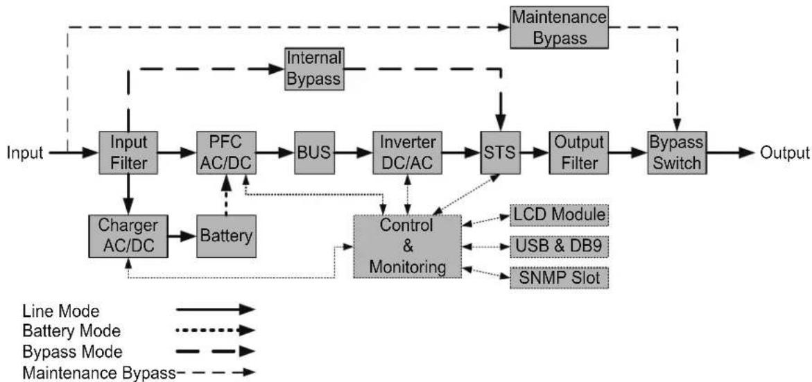
flowchart
graph TD
    A["Input"] --> B["Input Filter"]
    B --> C["PFC AC/DC"]
    C --> D["BUS"]
    D --> E["Inverter DC/AC"]
    E --> F["STS"]
    F --> G["Output Filter"]
    G --> H["Bypass Switch"]
    H --> I["Output"]

    J["Internal Bypass"] --> B
    K["Line Mode"] --> L["Battery Mode"]
    L --> M["Bypass Mode"]
    M --> N["Maintenance Bypass"]

    O["Charger AC/DC"] --> P["Battery"]
    P --> Q["Control & Monitoring"]
    Q --> R["LCD Module"]
    Q --> S["USB & DB9"]
    Q --> T["SNMP Slot"]

    U["Maintenance Bypass"] --> H
HARDWARE INSTALLATION GUIDE
- Battery charge loss may occur during shipping and storage. Before using the UPS, it's strongly recommended to charge batteries for four hours to ensure the batteries' maximum charge capacity. To recharge the batteries, simply connect the UPS to its designated AC electrical service.
- When using PowerPanel® Business Edition software, connect either the serial or the USB cable between the computer and the corresponding port on the UPS. Note: If the USB port is used, the serial port will be disabled. They cannot be used simultaneously. After connecting to either the USB port or the serial port on the UPS, a computer with PowerPanel® Business Edition Agent software installed can control the operating schedule, battery test, outlets, as well as obtain UPS status information. However, other computers with PowerPanel® Business Edition Client software can only obtain UPS status information via LAN connection.
- Connect your computer, monitor, and any externally-powered data storage device (Hard drive, Tape drive, etc.) into the outlets only when the UPS is off and unplugged. DO NOT plug a laser printer, copier, space heater, vacuum, paper shredder or other large electrical device into the UPS. The power demands of these devices will overload and possibly damage the unit.
- To protect a fax machine, telephone, modem line or network cable, connect the telephone or network cable from the wall jack outlet to the jack marked "IN" on the UPS and connect a telephone cable or network cable from the jack marked "OUT" on the UPS to the modem, computer, telephone, fax machine, or network device.
- Press the ON/OFF switch to turn the UPS on. The Power-On indicator LED will turn on when activated. If an overload is detected, an audible alarm will sound and the UPS will continuously emit two beeps per second. For resetting the unit, unplug some equipment from the outlets. Make sure your equipment carries a load current within the unit's safe range, (refer to the technical specifications).
- This UPS is equipped with an auto-charge feature. When the UPS is connected to AC electrical service the battery will automatically charge, even when the unit is switched off.
INSTALLING YOUR UPS SYSTEM CONT.
HARDWARE INSTALLATION GUIDE CONT.
-
To maintain an optimal battery charge, leave the UPS connected to AC electrical service at all times.
-
Before storing the UPS for an extended period of time, turn the unit OFF. Then cover it and store it with the batteries fully charged. Recharge the batteries every three months to ensure good battery capacity and long battery life. Maintaining a good battery charge will help prevent possible damage to the unit from battery leakage.
-
The UPS has one USB port (default) and one serial port that allows connection and communication between the UPS and any attached computer running PowerPanel® Business Edition Agent software. The UPS can control the computer's shutdown during a power outage through the connection while the computer can monitor the UPS and alter various programmable parameters. Note: Only one communication port can be used at a time. The port not in use will automatically become disabled or the serial port will be disabled if both ports are attached.
-
EPO (Emergency Power Off) Port: EPO ports allow administrators the capability to connect the UPS unit to customer-supplied EPO switches. These installations give operators a single access point to immediately power-off all equipment connected to the UPS during an emergency.
-
To avoid electric shock, turn the unit OFF and disconnect the unit from utility power before hardwiring the UPS (in/out power cord). The in/out power cord MUST be grounded.
-
Please note the internal UPS temperature will increase when fans are not in operation or ventilation is obstructed. When the high temperature sensor activates protection, the UPS generates an alarm and shuts down to avoid unexpected equipment damage. When the over temperature occurs, please check the Troubleshooting section. If the condition persists, please contact CyberPower for technical support.
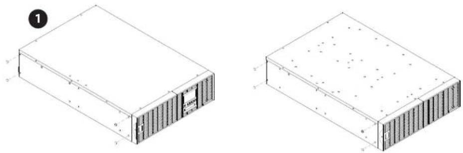
HARDWARE INSTALLATION
These versatile UPS systems can be mounted in a rackmount or vertical /tower orientation. This versatility is especially important to growing organizations with changing needs that value having the option to position a UPS on the floor or in the rackmount system. Please follow the instructions below for the respective mounting methods.
RACKMOUNT INSTALLATION: RACKMOUNT EARS INSTALLATION

Caution: Important Instructions
To prevent the risk of fire or electric shock, only use the supplied hardware to attach the mounting brackets.
Step 1: Remove the dust covers
Remove ten dust covers from the screw holes as shown below.
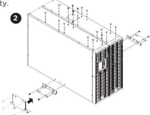
Step 2: Rackmount ear & hanging bracket installation
Attach two rackmount ears to the UPS using the provided flat head screws M5X7L*8pcs and tighten two hanging brackets with the pan head screws M5X6L*6pcs.

natural_image
Isometric line drawing of a server rack unit with ventilation ducts and ventilation grilles (no text or symbols)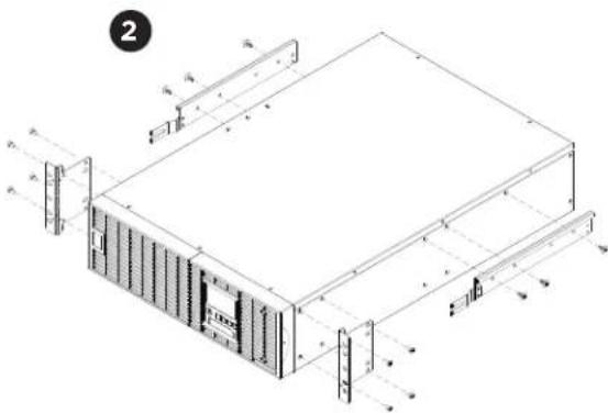
text_image
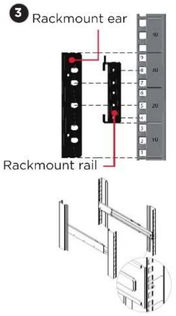
Technical diagram of a server rack with labeled dimensions and component layoutStep 3: Rackmount rail Installation
The rails adjust to mount in 19 in (48 cm) racks from 20.5 in to 36 in (52 cm to 91.5 cm) deep. Select the proper holes in the rack for positioning the UPS in the rack. The UPS uses 3 rack units, rack holes positions 1 through 9.
Position the guide screws on the rails into the rear rack square holes to temporarily support the rails in place. Tighten the front rail screws on the rack.
Step 4: Adjust rackmount rails to fit your rack
Adjust the rails depth to match your rack depth. Secure the rackmount rails to your rack using pan head screws M5X6L*4pcs and plastic washers *4pcs at the front of the rack. (Located in position 4 & position 8) Secure the rails to the rear of the rack using pan head screws M5X6L*4pcs and plastic washers *4pcs.
HARDWARE INSTALLATION CONT.
RACKMOUNT INSTALLATION: RACKMOUNT EARS INSTALLATION CONT.
text_image
3 Rackmount ear Rackmount rail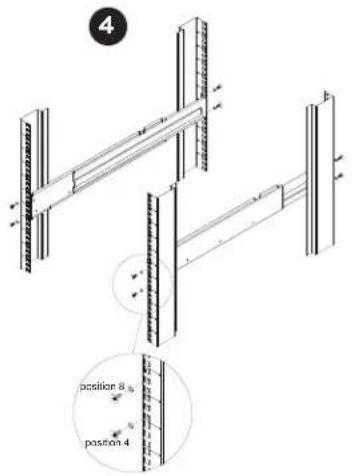
text_image
4 position 8 position 4
text_image
5 position 7 position 5 position 8 position 4Step 5: Place and secure the UPS on the rails
Slide the hanging brackets on the UPS on to the rails mounted in the rack with the front of the unit facing toward you. Secure the UPS to your rack with pan head screws M5X12L*4pcs at the front of the rack. (Located in position 5 & position 7)
Once completed, perform the same steps for the Battery module. Remove the internal battery trays from the Battery module before installing it. (See Battery Replacement section) The Battery module must be installed below the Power module. Place the internal battery trays back into the Battery module after installation. (See Battery Replacement section)
NOTE: To slide the UPS out from the rack
The UPS will be secured by a safety locking mechanism midway of pulling it out of the rack. Use both hands to hold the UPS and press the safety locking tab to pull the UPS out.

text_image
Technical diagram showing structural components with magnified views and dimension annotations
natural_image
Isometric technical line drawing of a server rack with vertical connectors and mounting points (no text or symbols)
natural_image
Pure geometric diagram of a rectangular frame with vertical and horizontal lines, no text or symbols present.HARDWARE INSTALLATION CONT.
VERTICAL/TOWER INSTALLATION
Step 1: Adhere rubber pads
Adhere the protective rubber pads on the bottom side of power module and extended battery module.
natural_image
Two technical line drawings of a rectangular electronic device with internal components and mounting holes (no text or symbols)Step 2: Attach the base stands and attach the dust covers
Secure the tie bracket on top of the power module and extended battery module with the flat head screws (M5X7*4pcs). Insert dust covers into the screw holes that are not being used. Optionally, use the rack mount ears as tower stands. Screw them onto the power module and extended battery module with pan head screws M5X6L*4pcs for adding stability.
text_image
ty. 2 0 G G G G G G G G G G G G G G G G G G G G G G G G G G G G G G G G G G G G G G G G G G G G G G G G G G M M M M M M M M M M M M M M M M M M M M M M M M M M M M M M M M M M M M M MStep 3: Rotate the Multifunction LCD Control Panel
Unscrew the upper panel of the UPS. Separate the upper panel from the UPS. Gently lift the LCD control panel out. Rotate it to the tower orientation. Reinstall it for a tower configuration.

natural_image
Three technical line drawings of server rack units with internal components, shown from different angles (no text or symbols present)MAINTENANCE BYPASS MODULE INSTALLATION
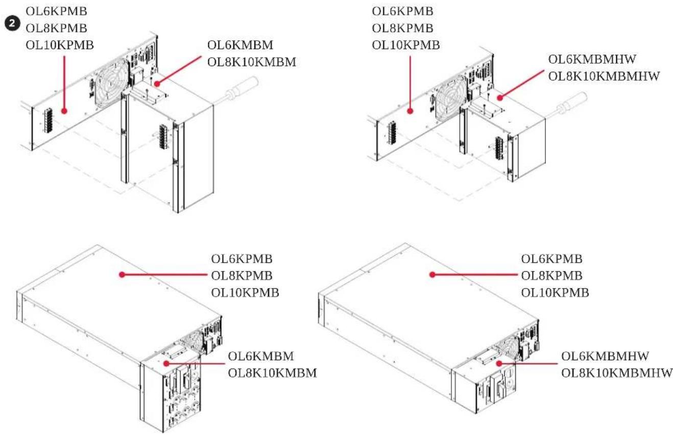
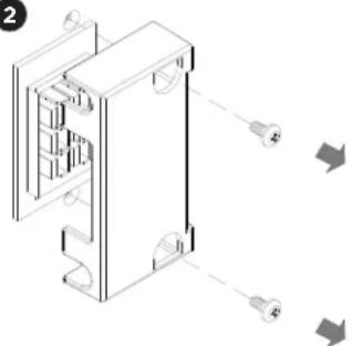
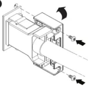
Step 1: Remove the cover from the Maintenance Bypass Module
Loosen the two screws and remove the cover from the Maintenance Bypass Module to expose the connectors.

text_image
OL6KMBMHW OL8K10KMBMHW OL6KMBM OL8K10KMBMStep 2: Attach the Maintenance Bypass Module to the Power Module
Align the connectors of the Maintenance Bypass Module with the connectors of the Power module to attach the device and tighten the two screws to fix the cover on the Maintenance Bypass Module. Secure the Maintenance Bypass Module to the Power module with four screws.
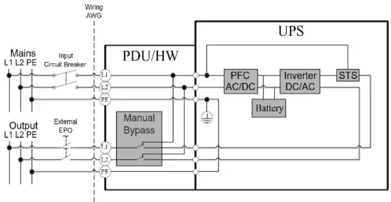
Check branch circuit breaker rating and wiring dimensions with the following table.
| UPS CAPACITY | BRANCH CIRCUIT BREAKER | WIRING AWG WIRING mm | 2 |
| 6KVA 40A 10 AWG 5.5 mm | 2 | ||
| 8KVA 50A 8 AWG 8.0 mm | 2 | ||
| 10KVA 70A 6 AWG 14.0 mm | 2 |
INPUT/OUTPUT CONFIGURATION
Hardware the input/output terminals as shown in the following diagram.
flowchart
graph TD
    A["Input Circuit Breaker"] --> B["PDU/HW"]
    C["Mains L1 L2 PE"] --> D["L1"]
    D --> E["PF"]
    F["External EPO"] --> G["T1"]
    G --> H["PF"]
    I["Wiring AWG"] --> J["PDU/HW"]
    K["Manual Bypass"] --> L["PDU/HW"]
    M["Battery"] --> N["Inverter DC/AC"]
    N --> O["STS"]
    P["UPS"] --> Q["PFC AC/DC"]
    Q --> R["Ground"]
    style A fill:#f9f,stroke:#333
    style F fill:#f9f,stroke:#333
    style K fill:#ccf,stroke:#333

Caution: Important Instructions
Input and Output circuit breakers must be "OFF" during the installation process.
An additional two pole disconnect device is necessary during the installation process.
Disconnected EPO will immediately shut down the logic circuit output of the UPS. Wiring the EPO signal is optional.
Local safety rules may require a separate, external EPO to turn off output circuit breakers. Refer to local wiring rules, the EPO should use approved components.
Step 1: Remove the inspection window cover
Loosen the four screws to remove the inspection window cover.
Step 2: Remove the terminal block cover
Loosen the four screws to remove the terminal block cover.
MAINTENANCE BYPASS MODULE INSTALLATION CONT.
INPUT/OUTPUT CONFIGURATION CONT.
Step 3: Input configuration
Insert the input cable through the appropriate cable gland (not included) and connect the three wires to the input terminal block.
1
natural_image
Technical line drawing of a computer case with internal components and ventilation fan (no text or symbols)
natural_image
Technical line drawing of an industrial device with internal components and a circular component (no text or symbols)
text_image
Technical diagram of an electrical enclosure with labeled components and a corresponding schematic of AC input/output terminals.Step 4: Output configuration
Insert the output cable through the appropriate cable gland (not included) and connect the three wires to the output terminal block.
Warning!
A CyberPower Step-Down Transformer is required for supplying 120V output to connected equipment. To prevent damage to connected equipment, do not attempt to separate the output voltage, from the hardwire block or outlets, into two 120V outputs on this UPS. If you attempt to supply two separate 120V outputs to your equipment, that equipment can be damaged when the UPS switches to battery mode.
Step 5: Fix the terminal block cover on the Maintenance Bypass Module
Tighten the four screws to fix the terminal block cover on the Maintenance Bypass Module. Replace the inspection window cover using four screws.
4
natural_image
Technical line drawing of an internal mechanical or electronic device with no visible text or symbols
natural_image
Technical line drawing of an industrial power unit with internal components and fan (no text or symbols)
natural_image
Technical line drawing of a mechanical assembly with internal components and no visible text or symbols- If the Bypass circuit is shorted and the UPS is running in Line Mode or Battery Mode, backfeed protection will be active and the external isolation device (Magnetic Contactor) will open.
- Save your data and perform a controlled shutdown.
- Contact CyberPower for repair.
MAINTENANCE BYPASS MODULE INSTALLATION CONT.
WITHOUT BACKFEED PROTECTION CONFIGURATION
- Hardwire the input terminals as shown in the following diagram.
- Do not remove the interconnection wires (Jumper1 / Jumper2) on "Backfeed Protection Connector".
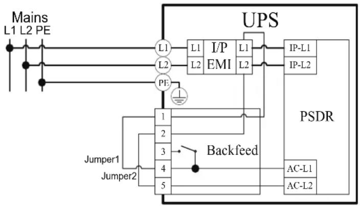
flowchart
graph TD
    A["Mains L1 L2 PE"] --> B["L1"]
    B --> C["L2"]
    C --> D["PE"]
    D --> E["Backfeed"]
    E --> F["PSDR"]
    G["IP-L1"] --> H["IP-L2"]
    I["AC-L1"] --> J["AC-L2"]
    K["PSDR"] --> L["Backfeed"]
    M["Jumper1"] --> N["Backfeed"]
    O["Jumper2"] --> P["Backfeed"]
    Q["UPS"] --> R["I/P EMI"]
    R --> S["L1 L2"]
    S --> T["Backfeed"]
    U["PSDR"] --> V["Backfeed"]
    W["Backfeed"] --> X["Backfeed"]
    Y["PSDR"] --> Z["Backfeed"]
WITH BACKFEED PROTECTION CONFIGURATION
- Connect a user supplied external isolation device (Magnetic Contactor) upstream and outside the UPS and capable of supporting the UPS input current.
- Remove the interconnection wires (Jumper1 / Jumper2) on "Backfeed Protection Connector".
- Hardwire the input terminals and "Backfeed Protection Connector" as shown in the following diagram.
- The external isolation device must be installed in the Mains path.
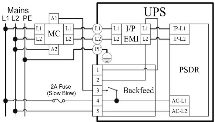
flowchart
graph TD
    A["Mains L1 L2 PE"] --> B["MC"]
    B --> C["L1"]
    B --> D["L2"]
    B --> E["A1"]
    B --> F["A2"]
    B --> G["L1"]
    B --> H["L2"]
    B --> I["L1"]
    I --> J["PE"]
    J --> K["1"]
    J --> L["2"]
    J --> M["3"]
    J --> N["4"]
    J --> O["5"]
    P["UPS"] --> Q["I/P EMI L1 L2"]
    Q --> R["IP-L1 IP-L2"]
    S["PSDR"] --> T["Backfeed"]
    U["2A Fuse (Slow Blow)"] --> V["AC-L1 AC-L2"]
EXTENDED BATTERY MODULE INSTALLATION
REAR PANEL DESCRIPTION
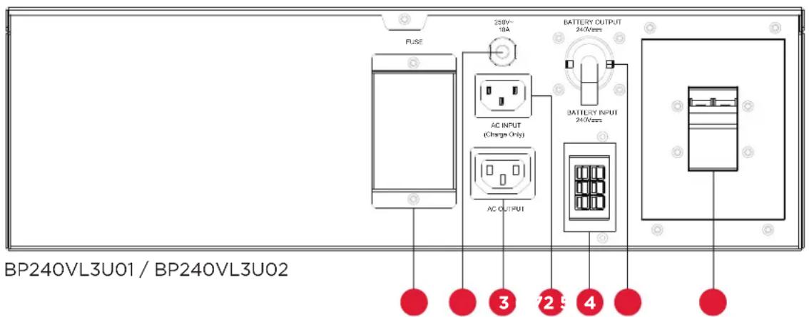
text_image
FUSE 250V~ 10A AC INPUT (Charge Only) AC OUTPUT BATTERY OUTPUT 240Vrms BATTERY INPUT 24Vrms BP240VL3U01 / BP240VL3U02 3 725 41. On-board Replaceable Fuse Cover
Replaceable fuse is accessible from the rear panel. Service to be performed by qualified personnel only.
2. AC Circuit Breaker
Provides overload and fault protection.
3. AC Output Outlet (IEC320 C13)
Use this outlet to connect to the AC Input Inlet of a downstream Battery module.
4. AC Input Inlet (IEC320 C14, Charge Only)
Connection for separate AC power source for Fast Charge Technology feature. NOT to be connected to UPS output as source of power.
5. Battery DC Input Connector
Use this input connector to daisy chain the next Extended Battery Module. Remove the connector cover for access.
6. Battery DC Output Cable
Use this output cable to connect the Extended Battery Module to the Power module or to the next Extended Battery Module.
7. Use the DC breaker to disconnect battery output.
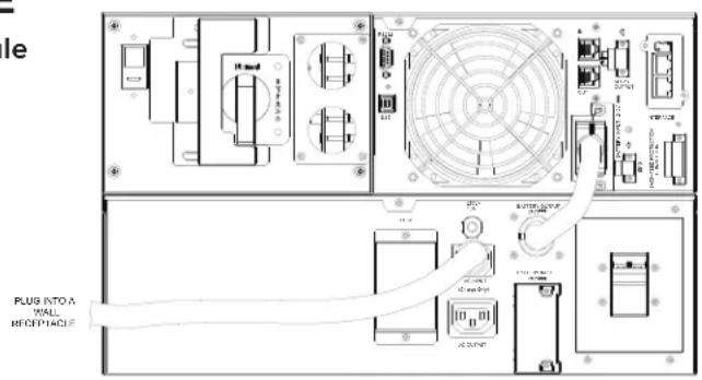
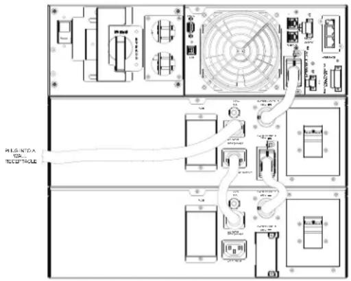
CONNECTION WITH POWER MODULE
Connection #1: Power module with one battery module
text_image
e PLUG INTO A WALL RECEPTACLEEXTENDED BATTERY MODULE INSTALLATION CONT.
CONNECTION WITH POWER MODULE CONT.
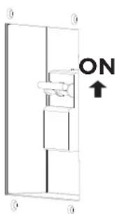
Step 1: Turn off the DC breaker on the EBM.
Step 2: Loosen the two screws to remove the battery cable retention bracket of the power module.
Step 3: Use the output cable of the EBM to connect the EBM to the Power module.
1

text_image
OFF2
natural_image
Isometric technical diagram of a mechanical or electrical component with labeled parts and directional arrows (no text or symbols)Step 4: Rotate the battery cable retention bracket and tighten the two screws to fix battery cable.
Step 5: Use a power cord to plug AC input inlet of the battery module into a wall receptacle.
Step 6: Turn on the DC breaker of the EBM.
4
natural_image
Technical line drawing of a mechanical assembly with no visible text or symbols6
text_image
ONConnection #2: Power module with multiple battery modules
text_image
PLC-NTDA PC-1023-1024-1025EXTENDED BATTERY MODULE INSTALLATION CONT.
CONNECTION WITH POWER MODULE CONT.
Step 1: Connect the 1st EBM to the Power module following the instructions above.
Step 2: Turn off the DC breaker of the 2nd EBM.
Step 3: Loosen the two screws to remove the battery cable retention bracket of the 1st EBM.
Step 4: Use the output cable of the 2nd EBM to connect the 2nd EBM to the 1st EBM.
2

text_image
OFF3

natural_image
Isometric technical diagram of a mechanical or electrical component with no visible text, numbers, or symbols.Step 5: Rotate the battery cable retention bracket and tighten the two screws to fix battery cable.
Step 6: Use a power cord to plug AC input inlet of the 2nd EBM into AC output outlet of the 1st EBM.
Step 7: Turn on the DC breaker of the 2nd EBM.
Step 8: Set the EBM number to the respective setting to match the number of installed units. To do this via the LCD control panel, go to the Configuration Menu, then scroll to EBM Number setting, select the appropriate number and Save the setting. This operation can also be done if there is an RMCARD installed in the UPS, or via PowerPanel® Business Edition Agent. Please see their respective User's Manuals for instructions.
5

natural_image
Technical diagram of a mechanical assembly with directional arrows indicating motion (no text or labels)7
text_image
ON ↑OPTIONAL LCD CONTROL PANEL INSTALLATION

Caution: Important Instructions
It must be done by qualified personnel.
To avoid electric shock, turn off and unplug the unit before proceeding with REMOTE CONTROL or WALL-MOUNTING INSTRUCTIONS.
REMOTE CONTROL
Step 1: Remove the Multifunction LCD Control Panel
Unscrew the right panel of the power module. Separate the right panel from the UPS. Gently lift the LCD module out. Reinstall the right panel.
Step 2: Connect a DB26 Cable
Connect a DB26 cable (not included) from LCD module to the "Remote Control Port" on the front panel as shown in the following figure.

natural_image
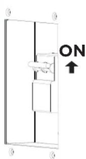
Isometric line drawing of a server rack unit with attached cable and connector (no text or symbols)WALL-MOUNTING INSTRUCTIONS
Step 1: Remove the Multifunction LCD Control Panel
Unscrew the right panel of the power module. Separate the right panel from the UPS. Gently lift the LCD module out. Reinstall the right panel.
Step 2: Rotate the DB26 Connector of LCD Control Panel
Step 3: Connect a DB26 Cable
Connect a DB26 cable (not included) from LCD module to the “Remote Control Port” on the front panel as shown in the following figure.
Step 4: Mount LCD Module on the Wall

natural_image
Diagram of a mechanical device with an attached component, showing no text or symbols.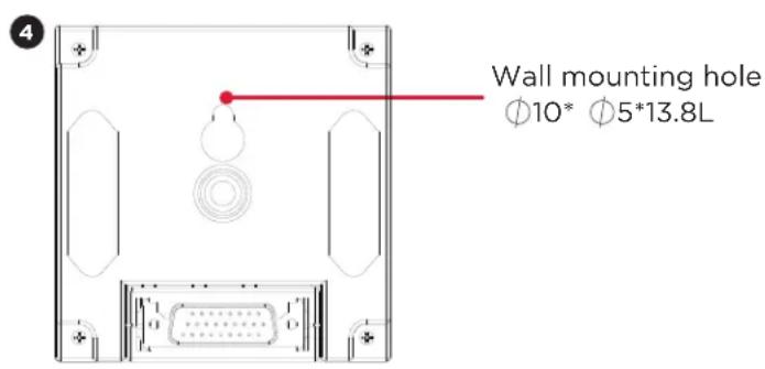
text_image
Wall mounting hole Ø10* Ø5*13.8LUPS SYSTEM STARTUP
After completing the hardware installation of the UPS, you are now ready to connect the UPS and connect your equipment.
To start the UPS:
- Verify that the UPS input cable or terminal blocks are connected to AC source.
- Verify that the EBM DC output cable is connected to the UPS DC connector.
- If UPS has a Maintenance Bypass Switch (MBS), verify that the switch is set to NORMAL and the Interlock Bracket is secured to right with the yellow screw.
- Set the EBM DC breaker to "ON" position.
- Set the UPS input circuit breaker to "ON" position.
- Set the upstream circuit breaker (not provided) to the "ON" position. The UPS LCD shows "CyberPower" and fans turn on.
- Press the ON/OFF button on the UPS front panel for at least 3 seconds to start the UPS.
- UPS will perform a brief self-test lasting about 15 seconds. The LCD will show result in the sequence below.

flowchart
graph TD
    A["CyberPower"] --> B["CyberPower Ready On"]
    B --> C["CyberPower FAN OK"]
    C --> D["CyberPower CHARGER OK"]
    D --> E["CyberPower DC BUS OK"]
    E --> F["CyberPower Battery Mode"]
    F --> G["CyberPower Line Mode"]
    H["CyberPower BATTERY OK"] --> I["CyberPower INVERTER OK"]
    I --> J["CyberPower Ready On"]
    J --> K["CyberPower Battery Mode"]
- Verify that the green "ON-LINE" LED illuminates solid, indicating that the UPS is operating in Line Mode and powering the output.
USING THE UPS SYSTEM
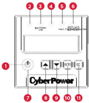
LCD CONTROL PANEL
text_image
1 2 3 4 5 6 BATTERY ON FAULT REPLACE BACKDOWN INF CyberPower 7 8 9 10 11LED INDICATORS - UPS STATUS
| ITEM | LED INDICATORS | COLOR | UPS STATUS DESCRIPTION |
| 1 | ON/OFF | White | UPS power is on. |
| 2 | ON-LINE | Green | UPS is operating in Line Mode. |
| 3 | BATTERY ON | Yellow | UPS is operating in Battery Mode. |
| 4 | BYPASS | Yellow | UPS is operating in Bypass Mode, Manual Bypass or ECO (Economy) Mode. |
| 5 | FAULT | Red | UPS has an internal fault. See “Trouble Shooting” for additional information. |
| 6 | REPLACE BATTERY | Red | Battery will soon need to be replaced due to insufficient runtime. |
BUTTON OPERATION
| ITEM | BUTTON | UPS MODES DESCRIPTION |
| 7 | ON/OFF | Press this button for at least 3 seconds to turn on or turn off UPS. |
| 8 | ▲ | Press this button to scroll up in the LCD menu. |
| 9 | ▼ | Press this button to scroll down in the LCD menu. |
| 10 | ENTER | Press this button to select an option. |
| 11 | ESC | Press this button to cancel or return to previous LCD menu. |
USING THE UPS SYSTEM CONT.
LCD CONTROL PANEL CONT.
| LCD SCREEN - UPS MODES OF OPERATION | |
| LCD SCREEN UPS MODES DESCRIPTION | |
| Line Mode | UPS is operating in Line Mode.The UPS is operating and protecting the equipment normally. |
| Battery Mode | UPS is operating in Battery Mode.A utility power failure has occurred. The UPS is using battery power to work and protect the equipment. |
| Bypass Mode | UPS is operating in Bypass Mode.A fault has been detected and the UPS transfers output to utility power. |
| Manual Bypass | UPS is operating in Manual Bypass.The UPS has been manually transferred to bypass for maintenance purposes. |
| ECO Mode | UPS is operating in ECO (Economy) Mode. If Bypass quality is within the ECO mode setting specifications, the UPS will operate in Bypass until input power is disqualified per set specifications. At that time the UPS will automatically switch to Line Mode. |
LCD MENU TREE
flowchart
graph TD
    A["MainMenu Information Configure EventLog"] --> B["ConfigureInformation"]
    A --> C["EventLog 5Events"]
    B --> D["O/PVolt"]
    B --> E["O/PFreq"]
    B --> F["I/PVolt"]
    B --> G["I/PFreq"]
    B --> H["O/PLoad"]
    B --> I["O/PAmp"]
    B --> J["O/PWatt"]
    B --> K["O/PVA"]
    B --> L["LoadEnergy"]
    B --> M["BATVolt"]
    B --> N["BATCap"]
    B --> O["BATRuntime"]
    B --> P["EBMNumber"]
    B --> Q["TEMP"]
    B --> R["SBM"]
    B --> S["Rating"]
    B --> T["MCUVer"]
    B --> U["ModelName"]
    B --> V["Date&Time"]
    B --> W["NextBATTChange"]
    B --> X["IP"]
    B --> Y["SubnetMask"]
    B --> Z["Gateway"]
    B --> AA["MAC"]
    C --> AB["OutputVoltage"]
    C --> AC["SyncFreqWindow"]
    C --> AD["BypassVWindow"]
    C --> AE["BypassCondition"]
    C --> AF["ECOMode"]
    C --> AG["ManualBypass"]
    C --> AH["UPSDiagnostic"]
    C --> AI["Batterystest"]
    C --> AJ["Alarmtest"]
    C --> AK["Indicatortest"]
    C --> AL["Fantcst"]
    C --> AM["AudibleAlarms"]
    C --> AN["EBMNumber"]
    C --> AO["WiringFault"]
    C --> AP["NCLControl"]
    C --> AQ["Language GeneratorMode"]
    C --> AR["Communication DryRelaySet"]
    C --> AS["ConverterMode ScreenSaver"]
    C --> AT["ClearEventLog ButtonOFFLOCK"]
    C --> AU["ChargerFunction SignalInputs"]
    C --> AV["ChargerCheck WithTransformer BackfeedCheck RestReplaceBAT IPAddress ResetLoadEnergy"]
USING THE UPS SYSTEM CONT.
LCD Control Panel Main Menu
Press "ENTER" button to enter the "Main Menu".
| MAIN MENU DESCRIPTION | |
| Information Displays the U | UPS information. |
| Configure Displays the U | PS settings that can be configured by the user. |
| Event Log | Displays the 5 most recent events, by event count, time (day/hour/minute), and event description. |
LCD Information Readout
There are 24 types of UPS information available for display.
- Press the "ENTER" button to enter the "Main Menu".
- Press the “▲” and “▼” buttons to scroll to the “Information” option.
- Press the "ENTER" button to select the "Information" submenu.
- Press the “▲” and “▼” buttons to scroll through the “Information” items shown in the table below.
- Press the "ESC" button to return to the UPS Status.
| INFORMATION MENU ITEMS | DATA DISPLAYED | DESCRIPTION |
| O/P Volt = XXX.XV | Displays the Output Voltage | |
| O/P Freq = XX.XHz | Displays the Output Frequency | |
| I/P Volt | = XXX.XV | Displays the Input Voltage |
| I/P Freq | = XX.XHz | Displays the Input Frequency |
| O/P Load | = XXX% | Displays the Output Load as a Percentage of Maximum Load |
| O/P Amp | = X.XA | Displays the Output Current |
| O/P Watt | = XXXXXW | Displays the Output Wattage |
| O/P VA | = XXXXXVA | Displays the Output VA |
| Load Energy | XXXX.XKWh | Display UPS Load Energy Consumption |
| BAT Volt | = XXX.XV | Displays the Battery Voltage |
| BAT Cap | = XXX% | Displays the Estimated Percentage of Battery Capacity |
| BAT Runtime | = XXXM | Displays the Estimated Battery Runtime in Minutes |
| EBM Number | = X | Displays the Number of Extended Battery Modules Configured |
| TEMP | = XX°C / XXX°F | Displays the Approximate Internal UPS Temperature in both °C (Celsius) and °F (Fahrenheit) |
| SBM | = XXXXX XH(M) | Displays the stage of Smart Battery Management with Operation Time |
| Rating | = XXK VA | Displays the UPS Rating |
| MCU Ver | XXXX | Displays the MCU Firmware Version |
| Model Name | Displays the UPS Model Name | |
USING THE UPS SYSTEM CONT.
LCD Information Readout Cont.
| INFORMATION MENU ITEMS | DATA DISPLAYED | DESCRIPTION |
| Date & Time - - - - / | - - / - - - - - Displays the present Date & Time | |
| Next BATT Change | XXX / XXXX Displays the next Battery Change Date & Time | |
| IP | XXXXXXXXXXX.XXX.XXX.XXX | Display the network IP address |
| Subnet Mask XXX.X | XX.XXX.XXX Display the network Subnet Mask | |
| Gateway XXX.XXX.X | XXX.XXX Display the network Gateway | |
| MAC | XX-XX-XX-XX-XX-XX | Display the network card MAC address |
LCD Event Log
The UPS will record the five most recent system events in the Event Log.
- Press the "ENTER" button to enter the "Main Menu".
- Press the “▲” and “▼” buttons to scroll to the “Event Log” option.
- Press the "ENTER" button to select the "Event Log" submenu.
| EVENT LOG SUBMENU | DESCRIPTION |
| (X) | Event date and time followed by event description. |
-
Press the “▲” and “▼” buttons to scroll through the “Event Log.” The UPS will record events listed in the table below.
-
Press the "ESC" button to return to UPS Status.
| EVENT CONTENT | DESCRIPTION |
| High O/P V | The UPS has detected Inverter voltage too High. |
| Low O/P V | The UPS has detected Inverter voltage too Low. |
| Output short | The UPS has detected output short. |
| Bus Fault | The UPS has detected DC Bus too High or Low. |
| Over Temp | The UPS has detected internal temperature too High. |
| Wiring Fault | The UPS has detected the input line/ neutral wire are reversed or without ground wire. |
| O/P Overload | The UPS has detected Output Watt or VA are too High. |
| Over Charge The Battery | has been charged too High voltage. |
| Charger Failure | The Battery Charger has malfunctioned. |
| Battery Low | The Battery has been discharged to low level. |
| Load Over Set% | The UPS has detected Output Watt or VA has exceeded user set parameter. |
USING THE UPS SYSTEM CONT.
LCD Event Log Cont.
| EVENT CONTENT DESCRIPTION | |
| Service Battery The Battery Replacement Date has reached the maintenance period. | |
| Battery Failure The UPS has detected battery failure. | |
| Line Abnormal | The UPS has detected the utility is out of range when the UPS is running auto-restart process. |
| Fan Error The UPS has detected a fan malfunction. | |
| BAT Disconnected The UPS has not detected batteries. | |
| Bypass Forbidden | User cannot use Manual Bypass function when Generator Mode or Converter Mode is enabled |
| Ready ON The UPS has been turned on. | |
| Battery Test The Batteries have been tested. | |
Multi-language Interface
Users can configure one of the four available languages for display:
[English] [Español-Spanish] [Français-French] [Deutsch-German]
- Press the "ENTER" button to enter the "Main Menu".
- Press the “▲” and “▼” buttons to scroll to the “Configure” option.
- Press the "ENTER" button to select the "Configure" submenu.
- Press the “▲” and “▼” buttons to scroll through the “Language” options.
- Press the "ENTER" button to select the "Language" submenu.
-
Press the “▲” and “▼” buttons to scroll to the language that you want to select. You may be prompted to save the selection, if so, press the “ENTER” button to save the setting.
-
Press the "ESC" button to cancel or return to previous LCD menu.
LCD Setting Configuration
There are 27 UPS settings that can be configured by the user.
- Press the "ENTER" button to enter the "Main Menu".
- Press the “▲” and “▼” buttons to scroll to the “Configure” option.
- Press the "ENTER" button to select the "Configure" submenu.
- Press the “▲” and “▼” buttons to scroll to the “Configure” items shown in the table below.
- Press the "ENTER" button to select the setting you want to configure.
- The first configuration parameter will be displayed on the second column of LCD screen.
- Press the “▲” and “▼” buttons to scroll through the different parameters.
USING THE UPS SYSTEM CONT.
LCD Setting Configuration Cont.
- Press the "ENTER" button to select the parameter you want to change.
- You may be prompted to save the selection, if so press the "ENTER" button to save the setting. Some options are saved and started automatically. (See the following table for additional details.)
- Press the "ESC" button to cancel or return to the previous LCD menu.
| CONFIGURE SUBMENU | AVAILABLE SETTINGS DEFAULT SETTING | |
| Output Voltage | = [200V] [208V] [220V] [230V] [240V]Sets UPS output voltage | 208V |
| Sync Freq Window | Range= [+/- 1%] [+/- 2%] [+/- 3%] [+/- 4%] [+/- 5%][+/- 6%] [+/- 7%] [+/- 8%] [+/- 9%] [+/-10%]Sets output synchronization frequency rangeIf input line frequency is outside this range, the UPS will lock in at the nominal frequency | +/- 5% |
| Bypass V Window | Range= [+10%/-10%] [+10%/-15%] [+10%/-20%][+15%/-10%] [+15%/-15%] [+15%/-20%]Sets Bypass Voltage range | +10%/-15% |
| Bypass Condition | [Check Freq/Volt] [Check Volt Only] [No Bypass]Bypass Condition:The default setting [Check Freq/Volt] means the UPS will check the the following specifications (1) and (2) when UPS has fault and needs transfer to Bypass.The setting [Check Volt Only] means the UPS will check the the following specification (1) when UPS has fault and needs transfer to Bypass.(1) Bypass voltage is inside the range of "Bypass V Window".(2) Bypass frequency is inside the range of "Sync Freq Range".The setting [No Bypass] means the UPS is forbidden to transfer to Bypass when UPS has fault. | Check Freq/Volt |
USING THE UPS SYSTEM CONT.
LCD Setting Configuration Cont.
| CONFIGURE SUBMENU | AVAILABLE SETTINGS DEFAULT SETTING | |
| ECO Mode1 | [Disable] [Enable] Disable | |
| [V Range= +/-15%] [V Range= +/-10%] (for [Enable])When ECO mode is enabled the UPS will check the following specifications of Bypass quality(1) Bypass voltage is inside the [V Range= +/-10%](default setting) or [V Range= +/-15%].(2) Bypass frequency is inside the +/-3Hz range of output nominal frequency. | V Range= +/-10% | |
| Manual Bypass | [Disable] [Enable]When performing UPS maintenance, the user can manually transfer the connected load to Bypass without interrupting the output to the connected equipment. | Disable |
| UPS Diagnostic | [Battery Test] [Alarm Test] [Indicator Test] [Fan Test] [Battery Test] | |
| [Activate?]Starts a manual battery test, UPS will operate 10 seconds on Battery mode to check battery condition.Starts a manual Alarm test, buzzer will sound for 5 seconds.Starts a manual Indicator test, UPS will light all LED and LCD background 5 seconds.Starts a manual Fan test, UPS will operate fan with full speed 5 seconds. | None | |
| Audible Alarms | [Disable] [Enable] [Only Battery Low]User can [Disable] or [Enable] the buzzer sound and also can set [Only Battery Low] to have alarm only when battery low on battery mode. | Enable |
| EBM Number | =[0][1][2][3][4][5][6][7][8][9][10]Sets the actual EBM (extended battery modules) number to get the correct estimated runtime. | 0 |
| Wiring Fault | [Disable] [Enable]Sets [Disable] or [Enable] the auto checking of Input wiring fault. | Disable |
| NCL Control | [Outlet On] [Outlet Off]Sets Non-Critical Load (NCL) [Outlet On] or [Outlet Off] directly. When the user sets NCL [Outlet Off], the NCL output power will turn off directly. | Outlet On |
USING THE UPS SYSTEM CONT.
LCD Setting Configuration Cont.
| CONFIGURE SUBMENU | AVAILABLE SETTINGS DEFAULT SETTING | |
| Language | [English] [Español-Spanish] [Français-French] [Deutsch-German]User can select the desired LCD control panel language. | English |
| Generator Mode2 | [Disable] [Enable]When the UPS input power source is a generator set the UPS will operate normally without transferring to Battery Mode when this is [Enable]. | Disable |
| Communication | [Disable] [Enable]All communication ports on the UPS are [Disable] or [Enable]. | Enable |
| Dry Relay Set | [I/P Power Fail] [Battery Low] [Summary Alarm][UPS On Bypass] [UPS Fail]Sets UPS events and convert to real potential-free Dry Contacts for industrial control. | I/P Power Fail |
| Converter Mode3 | [Converter Off] [O/P Freq = 50Hz] [O/P Freq = 60Hz]Sets [O/P Freq = 50Hz] or [O/P Freq = 60Hz] to convert the input frequency to required output frequency. | Converter OFF |
| Screen Saver | [Disable] [1 Minutes] [5 Minutes]Sets the amount of time the LCD screen stays on after no user input. The [Disable] option keeps the LCD screen on at all times. | 5 minutes |
| Clear Event Log | [Activate?]Clears all the events stored in the LCD Control Panel Event Log. | None |
| Button OFF LOCK | [Disable] [Enable]When [Enable] is set the Power ON/OFF Button is locked and will not function to prevent accidental UPS power ON/OFF operation. | Disable |
| Charger Function | [SBM] [Constant]Sets [SBM] to activate the Smart Battery Management to charge the batteries.Sets [Constant] to use trickle charge method to charge the batteries. | SBM |
USING THE UPS SYSTEM CONT.
LCD Setting Configuration Cont.
| CONFIGURE SUBMENU | AVAILABLE SETTINGS DEFAULT SETTING | |
| Signal Inputs | [Disable] [EPO] [ROO]Sets [EPO] (Emergency Power Off) to shutdown the UPS remotely when the contact is open.Sets [ROO] (Remote On/Off) to turn On the UPS remotely when the contact is close and turn Off the UPS remotely when the contact is open. The On/Off power button on front panel will be disabled when set to [ROO]. | Disable |
| Charger Check | [Disable] [Enable]Sets [Disable] or [Enable] to constantly monitor the charger function. | Disable |
| With Transformer | [Disable] [Enable]Sets [Enable] when UPS install with transformer. | Disable |
| Backfeed Check | [Disable] [Enable]Sets [Enable] to active Backfeed connector function. | Disable |
| Reset ReplaceBAT | [Activate?]Manually reset the Battery Replacement date. | None |
| IP Address | [Mode:DHCP] [Mode:Manual] Mode:DHCP | |
| [IP Address] [Subnet Mask] [Gateway] (for [Mode:Manual])Select [Mode:Manual] to set [IP Address] [Subnet Mask] [Gateway] to network interface (RMCARD) or select DHCP to set automatically. | None | |
| Reset Load Energy | [Activate?]Reset Load Energy Consumption (KWH) value. | None |
^1 This function can't be set when Manual Bypass, Generator Mode or Converter Mode is enabled.
^2 UPS has no bypass when Generator Mode is enabled.
^3 UPS has no bypass when Converter Mode is enabled. This function can only be set before the UPS is on.
Silencing Audible Alarms
- Press any of the four function buttons on the LCD module.
Note: the alarm cannot be turned off for a “Battery Low” condition. This condition will still result in an audible alarm.
- Change the "Audible Alarms" option to "Disable" in the LCD screen and it will no long give an audible alarm for any malfunction.
Manual Battery Test
Select “Activate” in the “Battery Test” option of the LCD screen and the unit will perform a manual battery test.
USING THE UPS SYSTEM CONT.
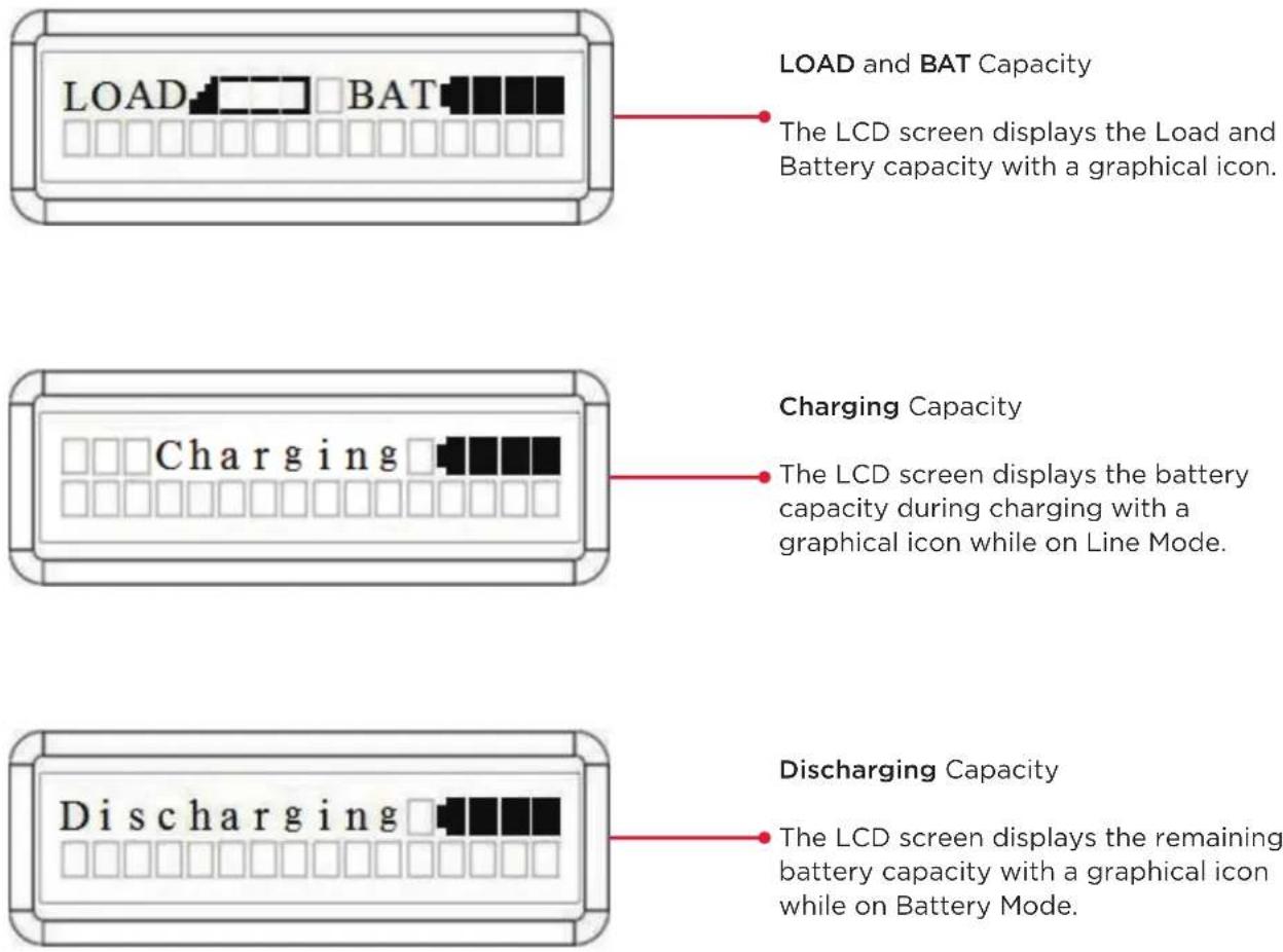
Graphic load/battery capacity display
- Press the "ESC" button to return to UPS Status.
- Press the "▲" and "▼" buttons to scroll to "LOAD" and "BAT" Capacity.
- Press the "▲" and "▼" buttons to scroll to "Charging" or "Discharging" Capacity.
text_image
LOAD and BAT Capacity The LCD screen displays the Load and Battery capacity with a graphical icon. Charging Capacity The LCD screen displays the battery capacity during charging with a graphical icon while on Line Mode. Discharging Capacity The LCD screen displays the remaining battery capacity with a graphical icon while on Battery Mode.MAINTENANCE
Storage
To store your UPS for an extended period, cover it and store with the battery fully charged. Recharge the battery every three months to ensure battery life.
Battery Replacement
Please read and follow the Safety Instructions before servicing the battery. Battery replacement should be performed by trained personnel who are familiar with the procedures and safety precautions. Make a note of the Replacement Battery module number.
Safety Precautions

Warning: High voltage - Risk of Electric Shock
Only use replacement batteries which are certified by Cyber Power Systems. Use of incorrect battery type is an electrical hazard that could lead to explosion, fire, electric shock, or short circuit.
Batteries contain an electrical charge that can cause severe burns. Before servicing batteries, please remove any conductive materials such as jewelry, chains, wrist watches, and rings.
Do not open or mutilate the batteries. Electrolyte fluid is harmful to the skin/eyes and may be toxic.
To avoid electric shock, turn off and unplug the UPS from the wall receptacle before servicing the battery.
Only use tools with insulated handles. Do not lay tools or metal parts on top of the UPS or battery terminals.
Replacement Batteries
Please refer to the front side of the EBM for the model number of the correct replacement batteries. For battery procurement, log onto www.cyberpowersystems.com, or contact your local dealer.
When Replace Battery LED is blinking or LCD displays Service Battery, use PowerPanel® Business Edition Agent software or log on to the RMCARD to perform a runtime calibration to verify battery capacity is sufficient and acceptable.
Battery Disposal

Do Not Discard
Batteries are considered hazardous waste and must be disposed of properly. Contact your local government for more information about proper disposal and recycling of batteries. Do not dispose of batteries in fire.
CyberPower Systems encourages environmentally sound methods for disposal and recycling of its UPS products.
Please dispose and/or recycle your UPS and batteries in accordance with local regulations.
MAINTENANCE CONT.
BATTERY REPLACEMENT
Step 1: Remove the front panels.
Step 2: Remove the retaining screws from the battery retention cover and then remove the cover itself.
Step 3: Pull the battery trays out slowly and then put the new battery trays into the compartment.
natural_image
Technical line drawings of server racks and storage compartments (no text or symbols)Step 4: Insert the battery connectors and tighten the screws of battery retention cover.
Step 5: Install the front panels. Execute a battery test via the LCD control panel, go to the Configuration Menu, then scroll to the UPS Diagnostic then select battery test and Activate, then scroll to Reset ReplaceBAT to reset the battery replacement date. This operation can also be done via PowerPanel® Business Edition Agent or RMCARD web interface. Please see their respective User Manuals for detailed instructions.

natural_image
Technical line drawings of a server rack unit with internal components and structural details (no text or symbols)MANUAL BYPASS SWITCH OPERATION
This operation allows qualified personnel to remove the detachable Maintenance Bypass Module from the Power Module for routine maintenance or replacement without disrupting power to connected equipment.

Caution: Important Instructions
It must be done by qualified personnel to prevent from the risk of fire or electric shock. Hazardous voltage may exist between the connectors of the Maintenance Bypass Module. Do not let the connectors touch any surface.
Do not slide the Interlock Bracket when the LCD screen shows "Generator On" or "Converter On".
Do not turn the Manual Bypass Switch when hearing a warning beep from the Power Module.
MAINTENANCE CONT.
Remove Maintenance Bypass Module
Step 1: Slide the Interlock Bracket to the left
Remove the yellow head screw that secures the Interlock Bracket. Slide the Interlock Bracket to the left.
Step 2: Check the Power module auto transfer to Manual Bypass
After Sliding the Interlock Bracket to the left, the Power Module will auto transfer to Manual Bypass. Check that the LCD screen shows "Manual Bypass" before turning the "Manual Bypass Switch" to "Bypass".
Step 3: Turn the "Manual Bypass Switch" to "Bypass"
Step 4: Press "ON/OFF" button to turn off UPS
Step 5: Pull the Maintenance Bypass Module away from the Power module
Loosen the four screws that hold the Maintenance Bypass Module to the Power module. Pull the Maintenance Bypass Module away from the Power module and loosen the two screws that hold the cover.
Step 6: Fix the cover on the Maintenance Bypass Module
Tighten the two screws and fix the cover on the Maintenance Bypass Module to hide the connectors.
natural_image
Technical line drawings of two 3D mechanical or electrical enclosure components, showing internal compartments and mounting holes (no text or symbols)
text_image
3 Up-4 TYPX200 O O O
text_image
BATTERY ON FULL BATTERY LINE CyberPower
natural_image
Technical line drawing of an internal device housing with exploded view, showing internal components and assembly (no text or symbols)
natural_image
Technical line drawing of a server rack unit with internal components and ventilation system (no text or symbols)The Power Module has now been safely shutdown and you can perform routine maintenance or replacement.
MAINTENANCE CONT.
Reattach Maintenance Bypass Module
Step 1: Remove the cover from the Maintenance Bypass Module
Loosen the two screws and remove the cover from the Maintenance Bypass Module to expose the connectors.
Step 2: Reattach the Maintenance Bypass Module to the Power Module
Reattach the Maintenance Bypass Module to the Power Module and tighten the two screws to fix the cover on the Maintenance Bypass Module.
Tighten the four screws that hold the Maintenance Bypass Module to the Power Module.
text_image
Technical diagram showing assembly of a server unit with labeled components and directional arrows indicating process flow.
text_image
Technical diagram showing assembly of a computer tower with labeled components and directional arrows indicating assembly steps.Step 3: Press "ON/OFF" button to turn the UPS on in "Manual Bypass"
WARNING: to avoid damage to the UPS, verify the Manual Bypass switch is set to "Bypass" and the Interlock Bracket is set to the left.
Step 4: Turn the "Manual Bypass Switch" to "Normal"
Step 5: Slide the Interlock Bracket to the right
Slide the Interlock Bracket to the right.
Install and tighten yellow head screw to secure the Interlock Bracket to the right.
Step 6: Check the Power Module auto transfer to Line Mode
After Sliding the Interlock Bracket to the right, the Power Module will auto transfer to Line Mode. Check the LCD screen shows "Line Mode".

text_image
3 BATTERY ON REFERENCE FAULTING CyberPower
text_image
4 H1.0m2
natural_image
Technical line drawing of two views of an electronic device casing with internal components and mounting holes (no text or symbols)TECHNICAL SPECIFICATIONS
| MODELS | OL6KRTMBOL6KRTHW | OL8KRTMBOL8KRTHW | OL10KRTMBOL10KRTHW |
| CONFIGURATION | |||
| Capacity (VA) 6000 VA 8 | 000 VA 10000 VA | ||
| Capacity (Watts) 6000 W | 8000 W 10000 W | ||
| Form Factor Rackmount/Tower | |||
| Energy-saving Technology | ECO Mode Efficiency>_96% ECO Mode Efficiency>_97% | ||
| INPUT | |||
| Input Voltage Range 200~240 V | |||
| Input Frequency Range 40~70 Hz (auto-sensing) | |||
| Input Power Factor 0.99 | |||
| Cold Start | Yes | ||
| OUTPUT | |||
| Output Waveform | Sine wave | ||
| Output Voltage | 200, 208, 220, 230, 240 V ±2% (Configurable) | ||
| Output Frequency | 50/60 Hz ±0.25 Hz (Auto-Sensing or Configurable) | ||
| Transfer Time (Typical) | 0ms | ||
| Rated Power Factor | 1 | ||
| Harmonic Distortion | THD < 3% at Linear Load, < 5% at Non-linear Load | ||
| Crest Factor | 3 : 1 | ||
| ECO Mode Bypass Voltage Range | ±10%, ±15% (Configurable) | ||
| Outlets for the Maintenance Bypass Module with Outlets | (2) L6-20R, (4) L6-30R, (1) Hard Wire 3-wire | ||
| Outlets for the Maintenance Bypass Module without Outlets | (1) Hard Wire 3-wire | ||
| PROTECTION | |||
| Surge Protection | IEC 61000-4-5 Level 3 (2430 Joules) | ||
| Phone / Network Surge Protection | RJ11/RJ45 (One In/One Out) | ||
| Overload Protection | Line Mode: 105-125% Load for 1 min, 126-150% Load for 10 secBattery Mode: 105-130% Load for 10 sec, 131-150% Load for 2 sec | ||
| Short Circuit Protection | UPS Output Cut off Immediately or Input Fuse / Circuit Breaker Protection | ||
| BATTERY | |||
| Specifications | (20) 12 V/7 Ah | (20) 12 V/9 Ah | |
| Recharge Time 0-90% (Typical) | 4 hours | 5 hours | |
TECHNICAL SPECIFICATIONS CONT.
| MODELS | OL6KRTMBOL6KRTHW | OL8KRTMBOL8KRTHW | OL10KRTMBOL10KRTHW |
| BATTERY CONT. | |||
| Sealed, Maintenance Free | Yes | ||
| Hot-Swappable Yes | |||
| STATUS INDICATORS | |||
| LCD Screen | Multi-Function LCD Readout that Supports:Multi-Language Interface, (24) Types of Read Out,(27) Types of Function Setting, (5) Event Logs | ||
| LED Indicators | Power On (White), Line Mode (Green), Battery Mode (Yellow),Bypass Mode (Yellow), Fault (Red), Replace Battery (Red) | ||
| Audible Alarms | Battery Mode, Battery Low, Overload, UPS Fault | ||
| MANAGEMENT & COMMUNICATIONS | |||
| On-Device Features | Start-up Self Test, Auto-Charge, Auto-Restart, Auto-Overload Recovery | ||
| Connectivity Ports (1) Serial Port (RS232), (1) USB Port, (1) Relay Out | |||
| SNMP/HTTP Capable | (1) Remote management card is pre-installed in expansion slot | ||
| SOFTWARE | |||
| Power Management Software | PowerPanel® Business Edition | ||
| PHYSICAL | |||
| Dimensions: Power Module | L x W x H = 26 x 17.05 x 5.2 in. (66 x 43.3 x 13.2 cm) | ||
| Dimensions: Battery Module | L x W x H = 26 x 17.05 x 5.2 in. (66 x 43.3 x 13.2 cm) | ||
| Dimensions: MBM/MBMHW | L x W x H = 6.3 x 7.8 x 10.4 in. (16 x 19.8 x 26.4 cm)/6.3 x 7.8 x 5.2 in. (16 x 19.8 x 13.2 cm) | ||
| Net Weight: Power Module | 52.8 lbs (24 kg) | ||
| Net Weight: Battery Module | 167.2 lbs (76 Kg) | 171.6 lbs (78 Kg) | |
| Net Weight: MBM/MBMHW | 13/4.9 lb (5.9/2.2 kg) | ||
| SAFETY | |||
| Conformance Approvals | CE, UL1778, FCC part 15 Class A | ||
| RoHS | RoHS Compliant | ||
TECHNICAL SPECIFICATIONS CONT.
| MODELS BP240VL3U01 BP240VL3U02 | ||
| CONFIGURATION | ||
| AC Input Voltage 180-280 V | ||
| DC Output Voltage 240 Vdc | ||
| DC Output Current 30 A 50 A | ||
| PHYSICAL | ||
| Dimensions L x W x H = 26 x 17 x 5.2in. (660 x 433 x 132 mm) | ||
| Net Weight | 167.2 lbs (76 Kg) | 171.6 lbs (78 Kg) |
| BATTERY | ||
| Specifications | (20) 12 V/7 Ah | (20) 12 V/9 Ah |
| Replacement Battery Cartridge | (2) RB1270X10 | (2) RB1290X10 |
| Recharge Time 0-90% (Typical) | 4 hours | 5 hours |
| Connector Type | PP45 | |
| Hot-Swappable | Yes | |
| Built-in Charger | Yes | |
| ENVIRONMENT | ||
| Operating Temperature | 32°F to 104°F (0°C to 40°C) | |
| Operating Relative Humidity | 0 to 90% Non-Condensing | |
| SAFETY | ||
| Conformance Approvals | CE, UL1778, FCC part 15 Class A | |
| RoHS | RoHS Compliant | |
TROUBLESHOOTING
| PROBLEM POSSIBLE CAUSE SOLUTION | ||
| WARNING | ||
| O/P Overload | Your equipment requires more power than the UPS can provide. If the UPS is in Line Mode then it will transfer to Bypass Mode; if the UPS is in Battery Mode it will shutdown. | Shut off non-essential equipment. If this solves the overload problem, the UPS will transfer to normal operation. |
| Load Over XXX% | Your equipment requires more power than the setting in the Power Management Software (PowerPanel® Business) will allow. | Shut off the non-essential equipment or increase the level in the Power Management Software. |
| Battery Mode UPS is operating on battery power. | Save your data and perform a controlled- shutdown. | |
| Battery Low | UPS is operating on battery power and will be shutting down soon due to extremely low battery voltage. | UPS will restart automatically when acceptable utility power returns. |
| BAT Disconnected Missing battery power. | Check battery connector and battery breaker. | |
| Battery Failure UPS has failed in Battery Test. | Check battery connector and battery breaker.Contact technical support to replace the battery. | |
| Replace Battery | Battery will need to be replaced soon due to insufficient runtime. | Install new batteries, execute battery test, and reset the replace battery date. |
| Service Battery | The Battery Replacement Date has reached the recommended 3 year maintenance period. | Perform a runtime calibration to verify battery capacity is sufficient and acceptable.If batteries have been recently replaced, then reset the Battery Replacement Date using PowerPanel® Business Edition-Agent software, RMCARD interface or through the LCD control panel on the UPS (See LCD Setting Configuration). |
| EPO OFF Missing the EPO connection. Check the EPO connection. | ||
| Wiring Fault* *Only applicable in areas where 200-240 V electrical service is provisioned with a Neutral line. | Line and neutral wires are reversed. Exchange line and neutral wires. | |
| Missing ground wire. Connect ground wire. | ||
| No ground wire. | Disable Wiring Fault alarm on LCD panel. | |
TROUBLESHOOTING CONT.
| PROBLEM POSSIBLE CAUSE SOLUTION | ||
| WARNING | ||
| Line Abnormal | Utility power is out of range for the UPS to auto-restart. | Check whether voltage or frequency of utility power is out of range. |
| Output Short Output short circuit. | Your attached equipment may have problems, please remove them and check again. | |
| Over Temperature | High temperature sensor activates protection. | Check the fan for operation and if the ventilation hole has been covered. |
| Cold start Lock | UPS is locked to prevent consuming battery power during shipping. | Connect UPS to utility power for first-time operation. |
| Auto restart Lock | “Automatic Restore” is disabled in Power Management Software (PowerPanel® Business) | Press “ON/OFF” button to turn on UPS |
| Bypass Forbidden | Manual Bypass Forbidden when the LCD screen shows “Generator On” or “Converter On”. | Slide the Interlock Bracket to the right. (For the Maintenance Bypass Module only) |
| FAULT | ||
| Over Charge Battery is overcharged. Remove battery connector and | check charger voltage.Contact CyberPower for assistance. | |
| Charger Failure Charger has failed. | ||
| High O/P V Output voltage is too high. | Shut down UPS and turn off input breaker.Contact CyberPower for assistance. | |
| Low O/P V Output voltage is too low. | ||
| Bus Fault | Internal DC bus voltage is too high or too low. | |
PRODUCT REGISTRATION
CyberPower requests that you complete and return the Warranty Registration Card enclosed with the Product or register the Product at its website (www.cyberpowersystems.com/registration) to establish that you are the Initial Customer of the Product, and therefore entitled coverage under the Limited Warranty and the Connected Equipment Guarantee. (Registration is not required for coverage, but note: if you do not register your purchase, you will be required to provide proof of purchase.)
LIMITED WARRANTY AND CONNECTED EQUIPMENT GUARANTEE
Read the following terms and conditions carefully before using the CyberPower OL6KRTMB/OL8KRTMB/OL10KRTMB/OL6KRTHW/OL8KRTHW/OL10KRTHW. By using the Product you consent to be bound by and become a party to the terms and conditions of this Limited Warranty and Connected Equipment Guarantee (together referred to as this "Warranty"). If you do not agree to the terms and conditions of this Warranty, you should return the Product for a full refund prior to using it.
Who is Providing this Warranty?
CyberPower Systems (USA), Inc. ("CyberPower") provides this Limited Warranty.
What Does This Warranty Cover?
This warranty covers defects in materials and workmanship in the Product under normal use and conditions. It also covers equipment that was connected to the Product and damaged because of the failure of the Product.
What is the Period of Coverage?
This warranty covers the Product for three years and connected equipment for as long as you own the Product.
Who Is Covered?
This warranty only covers the original purchaser. Coverage ends if you sell or otherwise transfer the Product.
How Do You Get Warranty Service?
- Before contacting CyberPower, identify Your Product model number, the Purchase Date, and each item of Connected Equipment.
- Email us at tech@cpsww.com or Call us at (877) 297-6937.
- If your product requires warranty service you must provide a copy of your dated purchase receipt or invoice.
LIMITED WARRANTY AND CONNECTED EQUIPMENT GUARANTEE CONT.
How Do You Open A Connected Equipment Claim?
- Call us at (877) 297-6937 or write to us at Cyber Power Systems (USA), Inc., 4241 12th Ave. E., STE 400, Shakopee, MN 55379, or send us an e-mail message to claims@cpsww.com for instructions, within 10 days of the occurrence.
- When you contact CyberPower, identify the Product, the Purchase Date, and the item(s) of Connected Equipment. Have information on all applicable insurance or other resources of recovery/payment that are available to the Initial Customer and Request a Claim Number.
- You must provide a dated purchase receipt (or other proof of the original purchase) for the Cyber Power unit and connected equipment. You also need to provide a description of the damage to your connected equipment.
- Pack and ship the product to CyberPower and, if requested, the item(s) of Connected Equipment, a repair cost estimate for the damage to the Connected Equipment, and all claim forms that CyberPower provides to you. Show the Claim Number on the shipping label or include it with the product. You must prepay all shipping costs, you are responsible for packaging and shipment, and you must pay the cost of the repair estimate.
How Long Do I Have To Make A Claim?
All claims must be made within ten days of the occurrence.
What Will We Do To Correct Problems?
CyberPower will inspect and examine the Product.
If the Product is defective in material or workmanship, CyberPower will repair or replace it at CyberPower's expense, or, if CyberPower is unable to or decides not to repair or replace the Product (if defective) within a reasonable time, CyberPower will refund to you the full purchase price you paid for the Product (purchase receipt showing price paid is required).
If it appears that our Product failed to protect any equipment plugged into it, we will also send you forms for making your claim for the connected equipment. We will repair or replace the equipment that was damaged because of the failure of our Product or pay you the fair market value (NOT REPLACEMENT COST) of the equipment at of the time of the damage. We will use Orion Blue Book, or another a third-party valuation guide, or eBay, craigslist, or other source to establish that amount. Our maximum liability is limited to \$300,000 for OL6KRTMB / OL8KRTMB / OL10KRTMB / OL6KRTHW/ OL8KRTHW / OL10KRTHW.
Who Pays For Shipping?
We pay when we send items to you; you pay when you send items to us.
LIMITED WARRANTY AND CONNECTED EQUIPMENT GUARANTEE CONT.
What Are Some Examples Of What This Warranty Does Not Cover?
-
This Warranty does not cover any software that was damaged or needs to be replaced due to the failure of the Product or any data that is lost as a result of the failure or the restoration of data or records, or the reinstallation of software.
-
This Warranty does not cover or apply to: misuse, modification, operation or storage outside environmental limits of the Product or the equipment connected to it, nor for damage while in transit or in storage, nor if there has been improper operation or maintenance, or use with items not designed or intended for use with the Product, such as laser printers, appliances, aquariums, medical or life support devices, etc.
What Other Limitations Apply?
The sole and exclusive remedies of the Initial Customer are those provided by this Warranty.
- This Warranty does not apply unless the Product and the equipment that was connected to it were connected to properly wired and grounded outlets (including compliance with electrical and safety codes of the most current electrical code), without the use of any adapters or other connectors.
- The Product must have been plugged directly into the power source and the equipment connected to the Product must be directly connected to the Product and not "daisy-chained" together in serial fashion with any extension cords, another Product or device similar to the Product, surge suppressor, or power tap. Any such installation voids the Limited Warranty.
-
The Product and equipment connected to it must have been used properly in a suitable and proper environment and in conformance with any license, instruction manual, or warnings provided with the Product and the equipment connected to it.
-
The Product must have been used at all times within the limitations on the Product's VA capacity.
The Product was designed to eliminate disrupting and damaging effects of momentary (less than 1ms) voltage spikes or impulses from lightning or other power transients. If it can be shown that a voltage spike lasting longer than 1ms has occurred, the occurrence will be deemed outside the rated capabilities of the Product and the Limited Warranty is void. CyberPower Does Not Cover or Undertake Any Liability in Any Event for Any of the Following:
- Loss of or damage to data, records, or software or the restoration of data or records, or the reinstallation of software.
-
Damage from causes other than AC Power Line Transients, spikes, or surges on properly installed, grounded and code-compliant 120 volt power lines in the United States and Canada; transients, surges or spikes on standard telephone land lines, PBX telephone equipment lines or Base 10T Ethernet lines, when properly installed and connected. (This exclusion applies, for example, to fluctuations in data transmission or reception, by CATV or RF transmission or fluctuations, or by transients in such transmission.)
-
Damage from any circumstance described as excluded above with respect to the Product.
-
Damages from fire, flood, wind, rain, rising water, leakage or breakage of plumbing, abuse, misuse or alteration of either the product or the Connected Equipment.
LIMITED WARRANTY AND CONNECTED EQUIPMENT GUARANTEE CONT.
What Other Limitations Apply? Cont.
- CyberPower excludes any liability for personal injury under the Limited Warranty and Connected Equipment Guarantee. CyberPower excludes any liability for direct, indirect, special, incidental or consequential damages, whether for damage to or loss of property [EXCEPT FOR (AND ONLY FOR) the specific limited agreement of CyberPower to provide certain warranty benefits regarding "Connected Equipment" under this Warranty], loss of profits, business interruption, or loss of information or data. NOTE: Some States or Provinces do not allow the exclusion or limitation of incidental or consequential damages, so the above limitation may not apply to you.
- The Product is not for use in high-risk activities or with aquariums. The Product is not designed or intended for use in hazardous environments requiring fail-safe performance, or for use in any circumstance in which the failure of the Product could lead directly to death, personal injury, or severe physical or property damage, or that would affect operation or safety of any medical or life support device (collectively, "High Risk Activities"). CyberPower expressly disclaims any express or implied warranty of fitness for High Risk Activities or with aquariums. CyberPower does not authorize use of any Product in any High Risk Activities or with Aquariums. ANY SUCH USE IS IMPROPER AND IS A MISUSE OF THE PRODUCT.
Where Can I Get More Information?
The application of the United Nations Convention of Contracts for the International Sale of Goods is expressly excluded.
CyberPower is the warrantor under this Limited Warranty.
For further information please feel free to contact CyberPower at
Cyber Power Systems (USA), Inc. | 4241 12th Ave E., STE 400, Shakopee, MN 55379 (877) 297-6937 | claims@cpsww.com
CONFORMANCE APPROVAL

FCC NOTICE
This device complies with part 15 of the FCC Rules. Operation is subject to the following two conditions: (1) This device may not cause harmful interference, and (2) this device must accept any interference that may cause undesired operation.
WARNING!! This equipment has been tested and found to comply with the limits for a Class A digital device, pursuant to part 15 of the FCC Rules. These limits are designed to provide reasonable protection against harmful interference when the equipment is operated in a commercial environment. This equipment generates, uses, and can radiate radio frequency energy and, if not installed and used in accordance with the instruction manual, may cause harmful interference to radio communications. Operation of this equipment in a residential area is likely to cause harmful interference in which case the user will be required to correct the interference at his own expense. Shielded signal cables must be used with this product to ensure compliance with the Class A FCC limits.
The Class A digital apparatus meets all requirements of the Canadian Interference-Causing Equipment Regulation.
This document is believed to be accurate, but CyberPower reserves the right to change or correct the contents and does not assume any responsibility for omissions or errors.
Need Additional Help?
Feel free to contact our Tech Support department with installation, troubleshooting, or general product questions.
CyberPower Technical Support
Phone: 1-877-297-6937
Email: tech@cpsww.com
Web: www.cyberpowersystems.com
Address: 4241 12th Avenue E, Suite 400 Shakopee, MN 55379, USA
Hours of Operation:
Monday - Friday, 7:00am - 6:00pm (CST)
CyberPower
Cyber Power Systems, Inc. | www.CyberPowerSystems.com
For USA and Canada | 4241 12th Ave East, Suite 400, Shakopee, MN 55379 | Toll-free: 877.297.6937
For all other regions | Please visit our website for local contact information.
Copyright © 2020 Cyber Power Systems, Inc. All rights reserve.