H63CD - Stove Wells - Free user manual and instructions
Find the device manual for free H63CD Wells in PDF.

User questions about H63CD Wells
0 question about this device. Answer the ones you know or ask your own.
Ask a new question about this device
Download the instructions for your Stove in PDF format for free! Find your manual H63CD - Wells and take your electronic device back in hand. On this page are published all the documents necessary for the use of your device. H63CD by Wells.
USER MANUAL H63CD Wells
265 Hobson Street, Smithville, Tennessee 37166
telephone: (800) 264-7827
www.wells-mfg.com

natural_image
Exterior view of a circular heating fan and a wall-mounted control panel (no text or symbols on the main components)OWNERS MANUAL
for
BUILT-IN
ELECTRIC
HOTPLATES
Models:
H336, H636 and
H706

natural_image
Exterior view of a portable stove with two circular burners and a control panel (no text or symbols visible)Includes
INSTALLATION
USE & CARE
EXPLODED VIEW
PARTS LIST
WIRING DIAGRAM
Model H706

natural_image
Silhouette of a person reading a book (no text or symbols visible)IMPORTANT: DO NOT DISCARD THIS MANUAL
This manual is considered to be part of the appliance and is to be given to the OWNER or MANAGER of the restaurant, or to the person responsible for TRAINING OPERATORS of this appliance. Additional manuals are available from your WELLS DEALER.
THIS MANUAL MUST BE READ AND UNDERSTOOD BY ALL PERSONS USING OR INSTALLING THIS APPLIANCE. Contact your WELLS DEALER if you have any questions concerning installation, operation or maintenance of this equipment.
LIMITED EQUIPMENT WARRANTY
Wells Manufacturing warrants to the original purchaser of new Wells products to be free from defects in material or workmanship, under normal and proper use and maintenance service as specified by Wells and upon proper installation and start-up in accordance with the instructions supplied with each Wells unit. Wells' obligation under this warranty is limited to a period of one [1] year from the date of original installation, or eighteen [18] months from original invoice date, whichever occurs first. Defects that occur as a result of normal use, within the time period and limitations defined in this warranty, will at Wells' discretion have the parts replaced or repaired by Wells or a Wells-authorized service agency.
THIS WARRANTY IS SUBJECT TO ALL LISTED CONDITIONS
Repairs performed under this warranty are to be performed by a Wells authorized service agency. Wells will not be responsible for charges incurred or service performed by non-authorized repair agencies. In all cases, the nearest Wells-authorized service agency must be used. Wells will be responsible for normal labor charges incurred in the repair or replacement of a warranted product within 50 miles (80.5 km) of an authorized service agency. Time and expense charges for anything beyond that distance will be the responsibility of the owner. All labor will need to be performed during regular service hours. Any overtime premium will be charged to the owner. For all shipments outside the U.S.A. and Canada, please see the International Warranty for specific details. It is the responsibility of the owner to inspect and report any shipping damage claims, hidden or otherwise, promptly following delivery. No mileage or travel charges will be honored on any equipment that is deemed portable. In general, equipment with a cord and plug weighing less than 50 lb. (22.7 kg) is considered portable and should be taken or shipped to the closest authorized service agency, transportation prepaid.
CONTACT
Should you require any assistance regarding the operation or maintenance of any Wells Manufacturing; phone or email our service department. In all correspondence provide the model number and serial number of the unit needing service; include the voltage or gas type.
Normal Business Hours: 8:00 a.m. to 4:30 p.m. Central
Telephone: 800-264-7827 Tech Service Option 2
Email: TechService@partstown.com
www.Wells-Mfg.com
| PRODUCTS | PARTS | LABOR |
| Universal Ventless Hoods (WVU) | 1 year | 1 year |
| Canopy Ventless Hoods (WVC) | 1 year | 1 year |
| "Cook and Hold" equipment (HW10, HWSMP, LLSC7, LLSC7WA, LLSC11, LLSC11WA) | 1 years | 1 year |
| Cast iron grates, burners and burner shields | 1 year | |
| Original Wells parts sold to repair Wells Equipment | 90 days |
WARRANTY EXCLUSIONS
THE FOLLOWING WILL NOT BE COVERED UNDER WARRANTY.
Wells' sole obligation under this warranty is limited to either repair or replacement parts, subject to the additional limitations detailed below. This warranty neither assumes nor authorizes any person to assume obligations other than those expressly covered by this warranty.
- Any product which has not been used, maintained, or installed in accordance with the directions published in the appropriate installation sheet and/or owner's manual, including incorrect gas or electrical connection. Wells is not liable for any unit which has been mishandled, abused, misapplied, subjected to harsh chemicals, modified by unauthorized personnel, damaged by flood, fire, or other acts of nature [or God], or which have an altered or missing serial number.
- Installation, labor, and job checkouts, calibration of heat controls, air and gas burner/bypass/pilot adjustments, gas or electrical system checks, voltage and phase conversions, cleaning of equipment, or seasoning of griddle surface.
- Replacement of fuses or resetting of circuit breakers, safety controls, or reset buttons.
- Replacement of broken or damaged glass components, quartz heating elements, and light bulbs.
- Labor charges for all removable and consumable parts in gas charbroilers and hotplates, including but not limited to burners, grates, and radiants.
- Any labor charges incurred by delays, waiting time, or operating restrictions that hinder a service technician's ability to perform service.
- Replacement of parts that fail or are damaged due to normal wear or labor for replacement of parts that can be replaced during a daily cleaning routine, such as but not limited to silicone belts, PTFE non-stick sheets, control labels, knobs, bulbs, fuses, quartz heating elements, baskets, racks, and grease drawers.
• Any economic loss of business or profits. - Non-OEM parts. Use of non-OEM parts without Wells' approval will void the warranty.
- Units exceeding one [1] year from original installation date, or more than eighteen [18] months from original invoice date, whichever comes first.
ADDITIONAL WARRANTIES
- Specific/chain-specific equipment may have additional and/or extended warranties.
The foregoing warranty is in lieu of any and all other warranties expressed or implied and constitutes the entire warranty.
TABLE OF CONTENTS
WARRANTY
SPECIFICATIONS 1
FEATURES & OPERATING CONTROLS 2
PRECAUTIONS & GENERAL INFORMATION 3
AGENCY APPROVAL INFORMATION 3
INSTALLATION 4
OPERATION 5
CLEANING INSTRUCTIONS 6
TROUBLESHOOTING 7
EXPLODED VIEW & PARTS LIST 8
PARTS & SERVICE 12 - 17
WIRING DIAGRAM 18 - 19
CUSTOMER SERVICE DATA 19
INTRODUCTION
Thank You for purchasing this Wells Manufacturing appliance.
Proper installation, professional operation and consistent maintenance of this equipment will ensure that it gives you the very best performance and a long, economical service life.
This manual contains the information needed to properly install this equipment, and to use and care for the equipment in a manner which will ensure its optimum performance.
SPECIFICATIONS
| MODEL | ELEMENT | VOLTS | AMPS | kW | *DIMENSIONS |
| H336 | Single 8" Coil | 208 V 1ø | 9.4 A | 2.0 kW | 10" outside diameter |
| 240 V 1ø | 10.8A | 2.6 kW | |||
| H636 | Dual 8" Coils | 208 V 1ø | 18.8 A | 3.9 kW | 14-3/4" W x 23-1/2" D |
| 240 V 1ø | 21.7 A | 5.2 kW | |||
| H706 | Dual 9" french plates | 208 V 1ø | 14.4 A | 3.0 kW | 14-3/4" W x 23-1/2" D |
| 240 V 1ø | 16.7 A | 4.0 kW |
Refer to Installation Instructions for cutout dimensions.
FEATURES & OPERATING CONTROLS
text_image
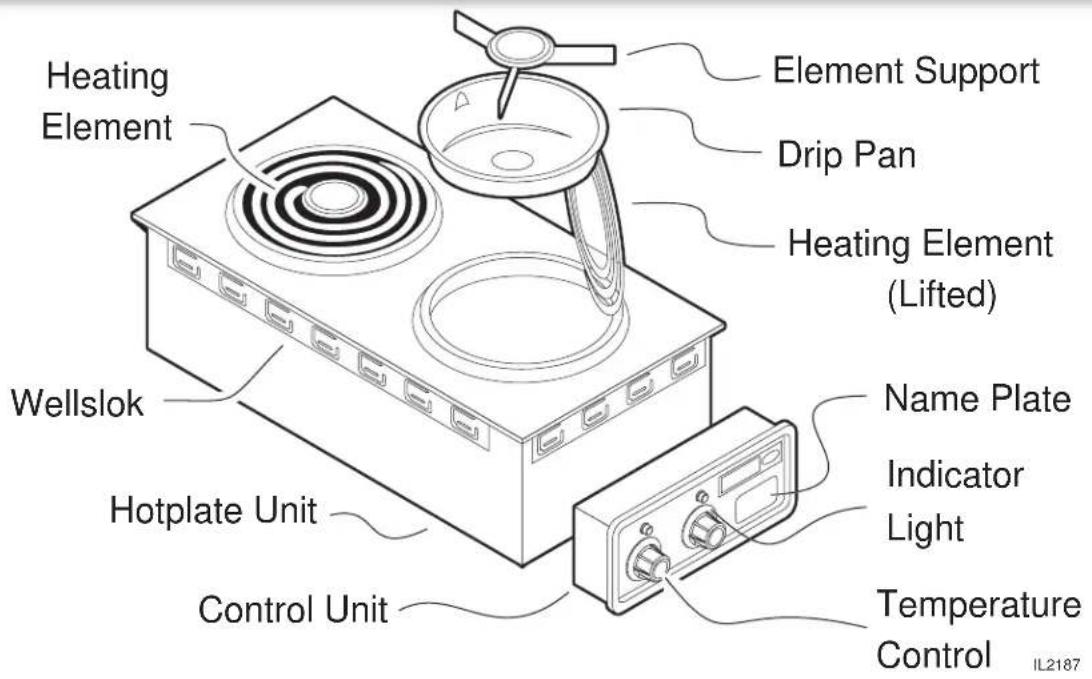
Heating Element Welllok Hotplate Unit Control Unit Element Support Drip Pan Heating Element (Lifted) Name Plate Indicator Light Temperature Control IL2187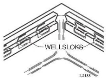
text_image
WELLSLOKS IL2188HOTPLATE UNIT:
| Heating Element | Provides heat for food preparation |
| Coil-type elements rotate for access to drip pan | |
| Note: Solid (french plate) elements on model H-706 do not lift | |
| Element Support* Holds coil-type element in proper position | |
| Drip Pan* | Collects drippings and holds element support. |
| Also deflects heat from element for more efficient cooking | |
| Wellslok Mounts hotplate | unit to counter |
| CONTROL UNIT: | |
| Temperature Control Infinite switch to control temperature of heating element | |
| Indicator Light | Clows any time temperature control is on |
| Name Plate | List manufacturer, model number and serial number, also lists voltage and wattage rating. |
CONTROL UNIT:
* = not used on model H706
PRECAUTIONS AND GENERAL INFORMATION
This appliance is intended for use in commercial establishments only.
This appliance is intended to prepare food for human consumption. No other use is recommended or authorized by the manufacturer or its agents.
Operators of this appliance must be familiar with the appliance use, limitations and associated restrictions. Operating instructions must be read and understood by all persons using or installing this appliance.
Cleanliness of this appliance is essential to good sanitation. Read and follow all included cleaning instructions and schedules to ensure the safety of the food product.
Hotplates with coil-type heating elements must be operated with drip pan and element support properly installed.
Disconnect the hotplate from electrical power before performing any maintenance or servicing.
DO NOT splash or pour water over or into interior of hotplate, control panel or wiring.
The technical content of this manual, including any wiring diagrams, schematics, parts breakdown illustrations and/or adjustment procedures, is intended for use by qualified technical personnel.
Any procedure that requires the use of tools must be performed by a qualified technician.
This manual is considered to be a permanent part of the appliance. This manual and all supplied instructions, diagrams, schematics, parts breakdown illustrations, notices and labels must remain with the appliance if it is sold or moved to another location.
This appliance is made in the USA. Unless otherwise noted, this appliance has American sizes on all hardware.

WARNING: ELECTRIC SHOCK HAZARD
All servicing requiring access to non-insulated electrical components must be performed by a factory authorized technician.
DO NOT open any access panel that requires the use of tools. Failure to follow this warning can result in severe electrical shock.

CAUTION: RISK OF DAMAGE
DO NOT connect and/or energize this appliance until all installation instructions are read and followed. Damage to the appliance will result if these instructions are not followed.
AGENCY APPROVAL INFORMATION
This appliance conforms to NSF Standard 4 for sanitation only if installed in accordance with the supplied Installation Instructions.
This appliance is Underwriters Laboratory recognized (FV). Since this appliance is only a single component of a complete installation, the finished installation of this FV unit requires additional evaluations to Underwriters Laboratory standards.
This unit is designed to be installed in a metal counter only.

STD 4

INSTALLATION
NOTE: DO NOT discard the carton or other packing materials until you have inspected the appliance for hidden damage and tested it for proper operation. Refer to SHIPPING DAMAGE CLAIM PROCEDURE on the inside front cover of this manual.

text_image
BOTTOM CHARGE COUNTER II:2180IMPORTANT:
Water damage caused by failure to seat Wellsloks or failure to install gasket or to seal flange to counter is NOT covered by warranty
IMPORTANT:
Contact a licensed electrician to install and connect electrical power to the hotplate.
IMPORTANT:
Damage due to being connected to the wrong voltage or phase is NOT covered by Warranty.
UNPACKING & INSPECTION
Carefully remove the hotplate from the carton. Remove all protective plastic film, packing materials and accessories from the hotplate before connecting the hotplate to electrical power or otherwise performing any installation procedure.
Carefully read all instructions in this manual and the Installation Instruction Sheet packed with the hotplate before starting any installation.
Read and understand all labels and diagrams attached to the hotplate.
Carefully account for all components and accessories before discarding packing materials. Store all accessories in a convenient place for later use.
PREPARATION
Carefully the Installation Instruction Sheet packed with the hotplate for cutout dimensions and restrictions.
Hotplate must be installed in a metal counter only.
Supplied gasket must be installed under the mounting flange, and the Wellsloks turned out to seal the hotplate and control unit to the counter.
Apply a thin bead of food-grade silicone sealant where the flange meets the counter.
ELECTRICAL
Hotplate must be installed by a licensed electrician in accordance with all applicable codes and ordinances.
Refer to the nameplate. Verify the electrical service power. Voltage and phase must match the nameplate specifications. Connecting the hotplate to the wrong voltage can severely damage the equipment or cause noticeably decreased performance.
The ground lug of the hotplate and control unit must be connected to a suitable building ground.
INSTALLATION NOTE: The installation of units requires additional evaluations to Underwriters Laboratory standards.
OPERATION
GENERAL OPERATIONAL NOTES
Carefully read the description of the hotplate operation on the specification sheet.
DO NOT attempt to perform any maintenance or service unless the hotplate is disconnected from electrical power.
DO turn the circuit breaker for the hotplate off before cleaning, servicing or performing any maintenance.
DO NOT use sharp objects or metal implements to clean the heating element(s).
DO use a plastic spatula or plastic scouring pad to remove burned-on food product.
OPERATION
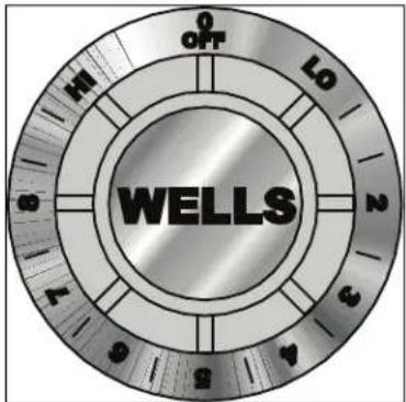
Each heating element is controlled by an infinite switch temperature control:
OFF removes power from the element
LOW thru 8 are temperature settings
Higher numbers indicate higher temperatures
There is a continuous range of settings between LOW and HI. HI is a continuous ON setting
The indicator light will glow any time the temperature control is on.
Cooking Recommendations:
Save energy by turning the temperature control off any time the hotplate is not in use. The coil-type heating elements will provide full heat within 30 seconds, while french plate heating elements will reach full heat within 2 minutes, making it unnecessary to leave the unit on during intermittent use.
Each heating element can hold up to a 16 quart pot or pan. For efficient heating of food product, pots and pans should be no more than 10" in diameter.
Maximize the efficiency of solid (french plate) elements by using flat-bottom pots and pans.
Stir thick liquids frequently to maintain a consistent temperature.

CAUTION: HOT SURFACES
Exposed surfaces can be hot to the touch and may cause burns.
text_image
OFF LO 3 WELLSIMPORTANT:
The dial markings are an INDICATION of temperature only. The temperature of the food product depends on many factors, including the size, shape and material of the food container, and the quantity and consistency of the food product.
CLEANING INSTRUCTIONS

CAUTION: ELECTRIC SHOCK HAZARD
Disconnect hotplate from electric power before cleaning.

CAUTION: BURN HAZARD
Allow hotplate element and cabinet to cool completely before cleaning.
CAUTION: ELECTRIC SHOCK HAZARD
Do not submerge hotplate in water.
IMPORTANT: DO NOT spill or pour water into interior of hotplate.
IMPORTANT: DO NOT spill or pour water into controls, control panel or wiring.
DO NOT submerge hotplate in water. Damage to internal components will occur. Damage to internal components from water damage is NOT covered by warranty.
DO NOT use metal implements, steel wool or metal scouring pads to clean heating elements.
PREPARATION
Unplug or disconnect hotplate from electrical power before cleaning. Allow hotplate to cool completely before cleaning.
FREQUENCY
Daily
TOOLS
Plastic Spatula and Plastic Scouring Pad Clean Cloth or Sponge Mild Detergent or Cleaner Formulated for Stainless Steel Warm Water
CLEANING
Disconnect hotplate from electrical power and allow heating elements to cool completely before cleaning.
COILED HEATING ELEMENTS:
Lift coiled heating elements and remove drip pans. Clean drip pans with a plastic spatula or plastic scouring pad, mild detergent and warm water. DO NOT use metal implements, steel wool or metal scouring pads to clean drip pans. Rinse drip pans by wiping with a clean cloth or sponge dampened with clean water.
Clean heating elements with a plastic spatula or plastic scouring pad, mild detergent and warm water. DO NOT use metal implements, steel wool or metal scouring pads to clean elements. Rinse by wiping with a clean cloth or sponge dampened with clean water.
Reinstall drip pans and gently lower heating element.
FRENCH PLATE HEATING ELEMENTS:
French plate elements do not lift. Clean heating elements with a plastic spatula or plastic scouring pad, mild detergent and warm water. DO NOT use metal implements, steel wool or metal scouring pads to clean elements. Rinse by wiping with a clean cloth or sponge dampened with clean water.
Dry exposed portions of hotplate unit and control unit by wiping with a clean soft dry cloth.
TROUBLESHOOTING
| SYMPTOM POSSIBLE CAUSE SUGGESTED REMEDY | ||
| Hotplate won't heat Disconnect OFF or circuit breaker tripped | Turn disconnect ON Check / reset circuit breaker | |
| One or more sections won't heat | Temperature control not on | Turn temperature control to desired setting |
| Damaged temperature control, element or other internal component | Contact Authorized Wells Service Agency for repairs | |
| Hotplate not hot enough | Temperature control not set Adjust for desired temperature | |
| Operating 208/240V unit at 120V | Be sure supply voltage matches nameplate voltage | |
| Damaged temperature control, element or other internal component | Contact Authorized Wells Service Agency for repairs | |
NOTE: There are no user serviceable components in this appliance. In all cases of damage or component malfunction, contact your Authorized Wells Service Agency for repairs.
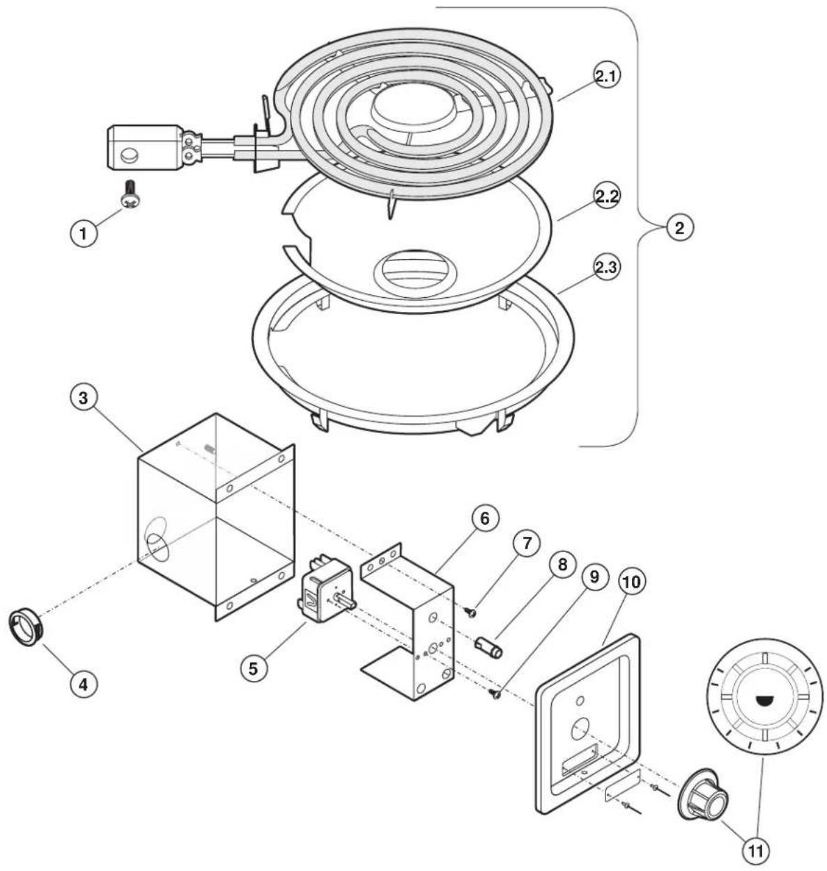
EXPLODED VIEW: H336
H336 BUILT-IN ELECTRIC HOTPLATE - 208/240V - SPIRAL ELEMENT
text_image
Technical diagram of a device assembly with numbered components and exploded view
text_image
WELLSModel: H336
Built-In Electric Hotplate - 208/240V Spiral Element
PL222
IL1799 Rev. A 6/24/09
PARTS LIST: H336
H336 Built-n Electric Hotplate, Spiral Element
| Fig No Part No Qty Description | |||
| 1 2C-38977 2 SCREW, 8-32X3/8-PHBNDHD | |||
| 2 WS-50293 1 ELEMENT ASSY KIT, 240V @ 2600W | |||
| 2.1 2N-30293ELUL 1 ELEMENT 240V 2600W | |||
| 2.2 2P-6468 1 RING-ELEMENT ADAPTOR | |||
| 2.3 2D-30293DT 1 DRIP TRAY | |||
| 3 P2-31033 1 BOX CONTROL | |||
| 4 2K-31040 1 BUSHING HEYCO 7/8” OD | |||
| 5 2E-30562 1 SWITCH INFINITE 240V | |||
| 6 P2-40843 1 BRKT MTG THERMO/INFINITE | |||
| 7 2C-38935 1 SCREW 6ABX5/16 PH PAN SMS | |||
| 8 WS-50385 1 LIGHT SIGNAL RED PUSH ON TERM | |||
| 9 2C-31697 2 SCREW 8-32 X 3/16 PH RD HD | |||
| 10 I7-Z12221 | 1 PANEL, FRONT/CONTROL | ||
| 11 | 2R-30371 1 KNOB ASSY WARMERS | ||
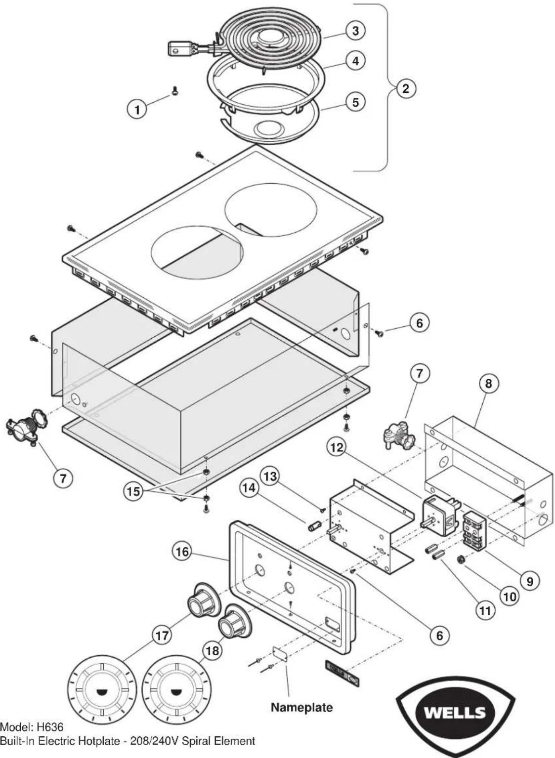
EXPLODED VIEW: H636
H-636 BUILT-IN ELECTRIC HOTPLATE - 208/240V - SPIRAL ELEMENT
text_image
Model: H636 Built-In Electric Hotplate - 208/240V Spiral Element Nameplate WELLSModel: H636
Built-In Electric Hotplate - 208/240V Spiral Element
PL222
IL1800 Rev. B 1/21/11
PARTS LIST: H636
| H636 Built-n Electric Hotplate, Spiral Element | |||
| Fig No Part No Qty Description | |||
| 1 2C-38977 4 SCREW, 8-32X3/8-PHBNDHD | |||
| 2 WS-50293 2 ELEMENT ASSY KIT, 240V @ 2600W | |||
| 3 2N-30293ELUL 2 ELEMENT 240V 2600W | |||
| 4 2P-6468 2 RING-ELEMENT ADAPTOR | |||
| 5 2D-30293DT 2 DRIP TRAY | |||
| 6 2C-31697 4 SCREW, 8-32X3/16 PH RD HD | |||
| 7 2K-37748X 2 FTG CONDUIT STRAIGHT 3/8 | |||
| 8 E7-49046 1 BOX OUTLET | |||
| 9 WS-50131 1 TERM BLK KIT-3 POLE, 85AMP | |||
| 10 2C-35736 2 NUT 8-32 HEX | |||
| 11 2C-41974 2 NUT 8-32 HEX 7/8 LONG ALU | |||
| 12 2E-30562 2 SWITCH INFINITE 240V | |||
| 13 2C-33935 4 SCREW 6ABX1/16 PH PAN | |||
| 14 WS-50385 2 LIGHT SIGNAL RED PUSH ON | |||
| 15 2C-31053 8 NUT 8-32 KEPS MS NICKEL | |||
| 16 P2-Z12288 | 1 PNL,CNTRL | ||
| 17 2R-30584 1 KNOB RR | |||
| 18 2R-30583 1 KNOB FR | |||
EXPLODED VIEW: H706
H-706 BUILT-IN ELECTRIC HOTPLATE - 208/240V - SOLID (FRENCH PLATE) ELEMENT

text_image
Model: H706 Built-In Electric Hotplate - 208/240V Solid (French Plate) Element PL222 IL1801 Rev. B 1/21/11222 p/n 2M-303734 Owners Manual Built-In Hotplates
PARTS LIST: H706
| H706 Built-In Electric Hotplate, French Plate | |||
| Fig No Part No Qty Description | |||
| 1 WS-503973 2 ELEM HPLATE UPGRADE FUSED | |||
| 2 WS-503972 2 HPLATE UPGRADE CRACKED CE | |||
| 3 2C-38935 8 SCREW 6AB X 5/16 PH PAN SMS | |||
| 4 2C-31053 2 NUT 8-32 KEPS MS NICKEL | |||
| 5 2C-31697 4 SCREW 8-32X3/16 PH RD HD | |||
| 6 2K-37748X 2 FTG CONDUIT STRAIGHT 3/8 | |||
| 7 2C-31053 6 NUT 8-32 KEPS MS NICKEL | |||
| 8 WS-50385 2 LIGHT SIGNAL RED PUSH ON | |||
| 9 2E-30562 2 SWITCH INFINITE 240V | |||
| 10 E7-49046 1 BOX OUTLET | |||
| 11 WS-50131 1 TERM BLOCK KIT RETRO | |||
| 12 2C-35736 1 NUT 8-32 HEX KEPS MS GREEN | |||
| 13 2C-41974 2 NUT 8-32 HEX 7/8 LONG ALU | |||
| 14 2R-30583 1 KNOB ASSY FRONT HOTPLATE | |||
| 15 2R-30584 1 KNOB RR | |||
| 16 P2-Z12288 1 PNL, CNTRL | |||
| 17 I7-37930 | 1 CHANNEL | ELEM MOUNT H706 | |
WIRING DIAGRAM
WIRING DIAGRAM
ELECTRIC COUNTERTOP HOTPLATES
H-336

text_image
HEATING ELEMENT PILOT LIGHT CONNECTOR L1 L2 TOP INFINITE SWITCH P L1 L2 H1 H2 ① ② ③ ④ ⑤ VOLTS NOMINAL AMPS 208 9.4 50 Hz 240 10.8 REV. G P/N 31850| VOLTS | NOMINAL AMPS |
| 208 | 9.4 |
| 240 | 10.8 |
WIRING DIAGRAM
WIRING DIAGRAM
ELECTRIC COUNTERTOP HOTPLATES
H-636, H-656 and H-706

text_image
ELEMENT GROUND FOR H-63, H-636, H-65 & H-115 ONLY PILOT LIGHT (2) HEATING ELEMENT (2) SINGLE PHASE CORD CONNECTED THREE PHASE CONTROL PANEL GROUND FOR H-706 AND H-636 ONLY * SIGNAL LIGHT WIRES #9 AND #10 ARE NOT REQUIRED BY H-706 AND H-636 * SWITCH (2)| MODELS | VOLTS | AMPS 3 PHASE | AMPS 1 PHASE | FREQ. | ||
| L1 | L2 | L3 | ||||
| H-70 AND H-706 | 208 | 12.5 | 7.2 | 7.2 | 14.4 | 50/Hz60 |
| 240 | 14.4 | 8.3 | 8.3 | 16.7 | ||
| H-63, H-65AND H-636 | 16.3 | 9.4 | 9.4 | 18.8 | ||
| 18.8 | 10.8 | 10.8 | 21.7 | |||
| H-115 | 120 | - | - | - | 13.8 | |
REV. A P/N 300093
NOTES
PARTS & SERVICE
DESCRIPTION SERVICE
Drip Tray, 8" for H-636 2D-30293DT
PART NO.
IMPORTANT: Use only factory authorized service parts and replacement filters.
For factory authorized service, or to order factory authorized replacement parts, contact your Wells authorized service agency, or call:
Wells Manufacturing
265 Hobson Street Smithville, Tennessee 37166 U.S.A.
Service Dept. phone: (800) 264-7827
Service Parts Department can supply you with the name and telephone number of the WELLS AUTHORIZED SERVICE AGENCY nearest you.
CUSTOMER SERVICE DATA
please have this information available if calling for service
RESTAURANT ____ LOCATION ____
INSTALLATION DATE ____ TECHNICIAN ____
SERVICE COMPANY
ADDRESS ____ STATE ____ ZIP ____
TELEPHONE NUMBER (____) - EQUIPMENT MODEL NO.
EQUIPMENT SERIAL NO.
VOLTAGE: (check one) 120 □ 208 □ 240 □

Wells Bloomfield proudly supports CFESA Commercial Food Equipment Service Association
SERVICE TRAINING - QUALITY SERVICE

text_image
Genuine Parts Protect - YOU - All - WaysCUSTOMER SATISFACTION

text_image
WELLSWELLS MANUFACTURING
265 Hobson Street, Smithville, Tennessee 37166
telephone: (800) 264-7827
www.wells-mfg.com