NLBB72N - Fridge Norlake - Free user manual and instructions
Find the device manual for free NLBB72N Norlake in PDF.

User questions about NLBB72N Norlake
0 question about this device. Answer the ones you know or ask your own.
Ask a new question about this device
Download the instructions for your Fridge in PDF format for free! Find your manual NLBB72N - Norlake and take your electronic device back in hand. On this page are published all the documents necessary for the use of your device. NLBB72N by Norlake.
USER MANUAL NLBB72N Norlake
BACK BAR REFRIGERATION Installation, Operation and Maintenance Instructions
INSPECTION
When the equipment is received, all items should be carefully checked against the Bill of Lading to ensure all crates and cartons have been received. Do not sign the freight bill clear until the freight has been properly inspected for damage. All units should be inspected for damage including concealed damage by uncrating immediately. If any damage is found, it should be reported to the carrier at once, noted on the Bill of Lading and a claim should be filed with the carrier. This equipment has been inspected and tested in the manufacturing facility and has been crated in accordance with transportation rules and guidelines. The manufacturer is not responsible for freight loss or damages.
INSTALLATION
After removing the unit from the packaging, clean the interior and exterior surfaces of the unit with soap and water and a rinse with clean water. Do not use chlorinated cleaners on the surfaces as they can cause corrosion.
This unit is designed for indoor use only. Be sure to locate the unit where the floor can support the weight of the unit and product installed inside of it. The refrigeration system located at the bottom left of the unit requires free air access for proper operation. Allow a minimum of seven (7) inches between the back of the cabinet and the wall. Do not locate the unit next to heat generating equipment or in direct sunlight.
Confirm that the proposed electrical outlet has the correct voltage, frequency and current carrying capacity for the requirements of the unit. This information is noted on the data plate on the inside left wall of the unit. The unit should be isolated on a circuit. Do not use an extension cord to get power to the unit. Improper electrical installations will void the compressor warranty. To prevent shock and fire, be sure the unit is properly grounded.
Local health codes may require that the unit be sealed to the floor with an NSF approved silicone sealant if it is not on legs or casters. After the unit is set in its desired location, simply apply a bead of sealant around the base of the unit and smooth it out.
The shelves and shelf support clips are shipped inside the cabinet. Install the shelf support clips on the pilasters mounted on the inside walls of the cabinet and set the shelves on the supports. The shelves are adjustable in 12 " increments to suit your needs.
If the doors have come out of alignment during shipping, they will need to be adjusted. This can be accomplished by opening the door(s) and loosening the screws that hold both the top and bottom hinges to the cabinet. After adjusting the door so it is aligned correctly, tighten the screws to securely hold the hinges and door(s) in place.
This cooler is designed to maintain your product temperature within the most desirable range of +34°F to +38°F. You can expect this temperature with the proper temperature control setting and in a normal environment. It is important to remember that when the product is delivered, it must be placed inside the cooler as soon as possible to avoid excessive warm up. If this happens, it may take many hours for the temperature to be reduced to the desirable range.
The temperature controller is located on the left end of the unit cooler. Turn the control clockwise for cooler temperatures and counterclockwise for warmer temperatures. Allow the unit several hours to respond to temperature control adjustments.
There are interior lights located above the door. The light has an on/off switch on the unit cooler.
When loading the cabinet with product, do not block the air flow path. Blocking the air flow may decrease performance. Maintain clearance between the contents and air duct for best performance.
This equipment is intended for the storage and display of pre-packaged food product only.
Cleaning
Beginning with the initial installation, the interior surfaces of the cabinet should be periodically cleaned with a solution of warm water and baking soda. This solution will remove any odors from spillage that has occurred. The exterior of the cabinet should also be cleaned frequently with a commercial stainless steel cleaner, glass cleaner or mild soap solution. Do not use chlorinated cleaners on any surfaces.
Note: do not use stainless steel cleaners or other solvent-based chemicals on the plastic parts (door handle or trim strips) as they can cause failure. Use mild soap and warm water on plastic parts.
The shelving can be cleaned in a sink with a mild soap solution and a soft bristled brush.
Condenser Coil
Prior to cleaning the condenser coil disconnect the unit from power. Periodic cleaning of the condenser coil will aid the heat transfer of the refrigeration system and increase its efficiency. To accomplish this, remove the lower front grill from the cabinet. The condenser coil is located behind the grill. Use a soft bristled brush to remove any dirt particles that are on the fins of the condenser coil. Use a vacuum cleaner or compressed air to remove the loosened particles. Replace the front grill and reconnect the unit to power. Failure to clean the condenser coil can lead to performance loss and compressor failure.
TROUBLESHOOTING
| Problem | Remedy |
| Compressor will not start | ·Check the power cord and make sure it is plugged in and has power.·Check the temperature controller. If it is in the “OFF” position, turn it clockwise to set a desired temperature. |
| Poor performance | ·Move the unit from direct sunlight.·Move the unit away from heating devices.·Install the unit in a well ventilated place, with at least 2 inches of clearance on all sides.·Clean the condenser if heavy dust is collected.·Clear contents from blocking the inside air duct.·Check the temperature controller for correct setting.·Check the doors and be sure they are completely closed. |
| Unit noisy | ·Install the unit on a level solid surface.·Maintain 2 inches of clearance from the wall.·Check for loose parts or mounting.·Keep the tubing free from any contact to avoid rattle. |
| Condensation on cabinet exterior and/or floor | ·Reduce humidity where the unit is installed.·Check the drain line to make sure it is not disconnected inside the cabinet and it drains into the drain pan in the compressor area. |
SPECIFICATIONS\*
| Model | # of Doors | # of Shelves | Electrical | Amps | NEMA Plug | HP | Refrigerant | Capacity 12oz. cans |
| BB59 | 2 | 4 | 115/60/1 | 3.3 | 5-15P | 1/5 | R-134a | 1084 |
| BB59G | 2 | 4 | 115/60/1 | 5.0 | 5-15P | 1/5 | R-134a | 1084 |
| BB69 | 2 | 4 | 115/60/1 | 5.0 | 5-15P | 1/3 | R-134a | 1299 |
| BB69G | 2 | 4 | 115/60/1 | 5.0 | 5-15P | 1/3 | R-134a | 1299 |
| BB79 | 3 | 6 | 115/60/1 | 6.0 | 5-15P | 1/3 | R-134a | 1566 |
| BB79G | 3 | 6 | 115/60/1 | 6.3 | 5-15P | 3/8 | R-134a | 1566 |
| BB95 | 3 | 6 | 115/60/1 | 6.3 | 5-15P | 3/8 | R-134a | 1875 |
| BB95G | 3 | 6 | 115/60/1 | 6.3 | 5-15P | 3/8 | R-134a | 1875 |
* Above specifications are subjected to change without prior notice for quality improvement.
GLASS DOOR BB SERIES PARTS DIAGRAM
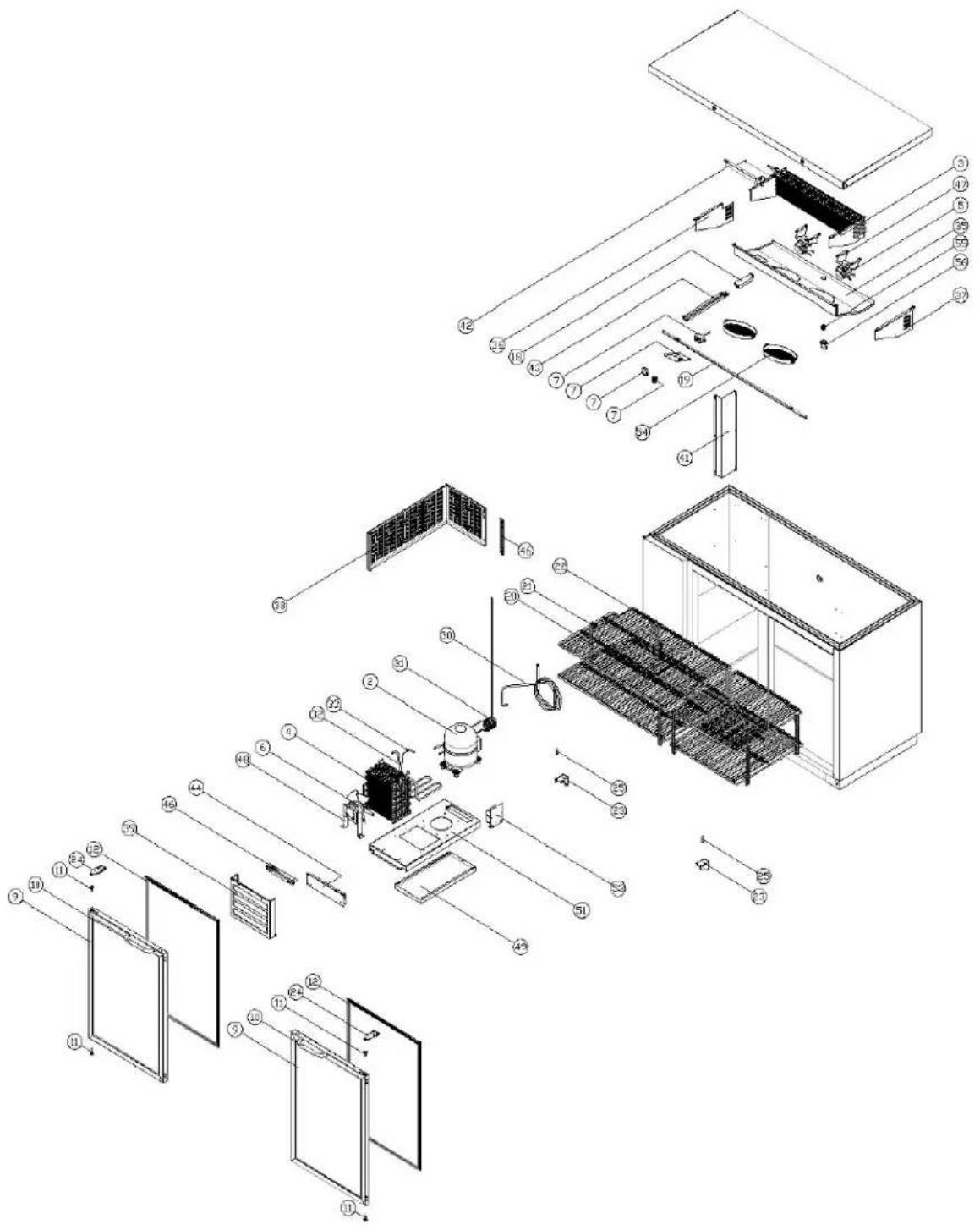
text_image
Exploded view diagram of a solar panel assembly with numbered components for identificationGLASS DOOR BB SERIES PARTS LIST
| ITEM NO. | PART NAME and DESCRIPTION | BB59 | BB69 | BB79 | BB95 | PART NO. |
| 2 | COMPRESSOR SD162C-L1U | X | 145735 | |||
| COMP ELECTRONIC KIT | X | 150445 | ||||
| COMPRESSOR SK182C-L2U | X | 160624 | ||||
| COMP ELECTRONIC KIT | X | 160625 | ||||
| COMPRESSOR SK1A1C-L2W | X | X | 150311 | |||
| COMP ELECTRONIC KIT | X | X | 150312 | |||
| 3 | EVAPORATOR | X | 157129 | |||
| EVAPORATOR | X | X | X | 157130 | ||
| 4 | CONDENSER | X | X | X | X | 157131 |
| 5 | EVAPORATOR FAN MOTOR | 2 | 145709 | |||
| EVAPORATOR FAN | 2 | 160627 | ||||
| EVAPORATOR FAN MOTOR | X | X | X | 157132 | ||
| EVAPORATOR FAN | X | X | X | 145750 | ||
| 6 | CONDENSER FAN MOTOR | X | X | X | X | 145748 |
| CONDENSER FAN | X | X | X | X | 145749 | |
| 7 | THERMOSTAT CONTROL | X | X | X | X | 160640 |
| THERMOSTAT PLATE | X | X | X | X | 145822 | |
| THERMOSTAT KNOB | X | X | X | X | 145730 | |
| LAMP SWITCH | X | X | X | X | 145729 | |
| 9 | DOOR ASSY LEFT | X | X | X | X | 157616 |
| DOOR ASSY RIGHT | X | X | X | 2 | 157617 | |
| DOOR ASSY RIGHT (CENTER DOOR ON BB79) | X | 157618 | ||||
| 10 | DOOR HANDLE | 2 | 2 | 3 | 3 | 159219 |
| 11 | DOOR BUSHING | 2 | 2 | 3 | 3 | 159220 |
| 12 | DOOR GASKET | 2 | 2 | 2 | 3 | 159221 |
| DOOR GASKET (CENTER DOOR ON BB79) | X | 159222 | ||||
| 18 | LED DRIVER | X | X | X | X | 157576 |
| 19 | LED LAMP 59 (1002mm) | X | X | X | X | 159223 |
| 20 | SHELF PILASTER | 9 | 9 | 13 | 13 | 145755 |
| 21 | SHELF CLIP | 18 | 18 | 26 | 26 | 145756 |
| 22 | SHELF LEFT | 2 | 2 | 2 | 2 | 157578 |
| SHELF CENTER | 2 | 2 | 157579 | |||
| SHELF CENTER | 2 | 4 | 157580 | |||
| SHELF RIGHT | 2 | 157582 | ||||
| 23 | HINGE BOTTOM LEFT | X | X | X | X | 162398 |
| HINGE BOTTOM RIGHT | X | X | 2 | 2 | 162399 | |
| 24 | HINGE TOP ASSY | 2 | 2 | 3 | 3 | 159226 |
| 30 | SUCTION PIPE ASSY | X | X | X | X | 157590 |
| 31 | CAPILLARY TUBE | X | X | X | X | 157591 |
| 32 | HOT PIPE | X | X | X | X | 157592 |
| 33 | SUCTION JOIN PIPE | X | X | X | X | 157593 |
| 34 | DRYER | X | X | X | X | 145714 |
| 35 | DUCT 59G | X | 157595 | |||
| DUCT 69G, 80G, 90G, 95G | X | X | X | 157596 | ||
| 36 | DUCT LEFT COVER | X | X | X | X | 157597 |
| 37 | DUCT RIGHT COVER | X | X | X | X | 157598 |
| 38 | SIDE PANEL | X | X | X | X | 157599 |
| 39 | FRONT PANEL | X | X | X | X | 157600 |
| 41 | PIPE COVER | X | X | X | X | 157601 |
| 42 | HARNESS & PIPE COVER | X | 157602 | |||
| HARNESS & PIPE COVER | X | 157603 | ||||
| HARNESS & PIPE COVER | X | 157605 | ||||
| HARNESS & PIPE COVER | X | 160924 | ||||
| 43 | LED HARNESS COVER | X | X | X | X | 157606 |
| 44 | CABINET BASE | X | X | X | X | 157607 |
| 51 | COMPRESSOR BASE | X | X | X | X | 157608 |
| 54 | EVAP FAN COVER | 2 | X | X | X | 157609 |
| 55 | EVAP DRAIN ELBOW A | X | X | X | X | 157684 |
| 56 | EVAP DRAIN ELBOW B | X | X | X | X | 157685 |
| 58 | MAIN HARNESS NOT SHOWN | X | 157612 | |||
| MAIN HARNESS NOT SHOWN | X | 160628 | ||||
| MAIN HARNESS NOT SHOWN | X | X | 157613 | |||
| 59 | COMPRESSOR HARNESS NOT SHOWN | X | X | X | X | 157614 |
| 60 | POWER CORD NOT SHOWN | X | X | X | X | 157615 |
| 61 | CASTER SET (4) 2 LOCKING & 2 NON-LOCKING PLATE TYPE | X | 136043 | |||
| CASTER SET (6) 3 LOCKING & 3 NON-LOCKING PLATE TYPE | X | X | X | 136044 | ||
| DOOR LOCK KEY | 2 | 2 | 3 | 3 | 160743 |
SOLID DOOR BB SERIES PARTS DIAGRAM
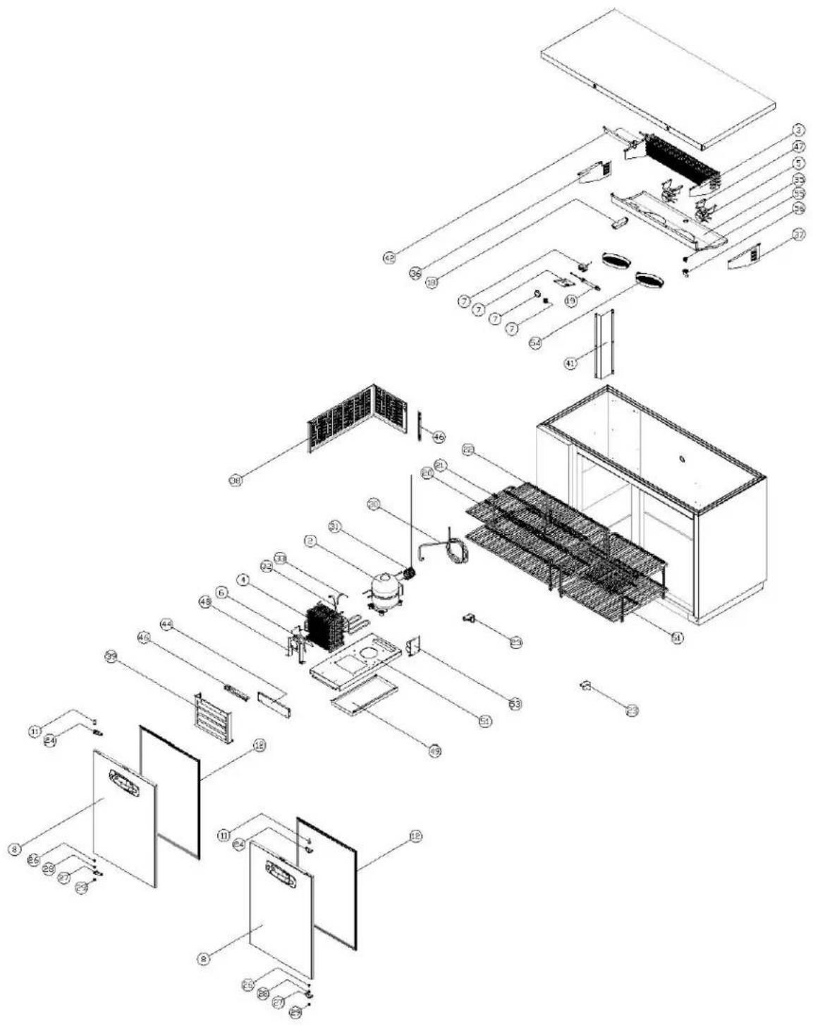
text_image
Exploded view diagram of a refrigerator assembly with numbered components for identificationSOLID DOOR BB SERIES PARTS LIST
| ITEM NO. | PART NAME and DESCRIPTION | BB59 | BB69 | BB79 | BB95 | PART NO. |
| 2 | COMPRESSOR SD162C-L1U | X | 145735 | |||
| COMP ELECTRONIC KIT | X | 150445 | ||||
| COMPRESSOR SK182C-L2U | X | X | 160624 | |||
| COMP ELECTRONIC KIT | X | X | 160625 | |||
| COMPRESSOR SK1A1C-L2W | X | 150311 | ||||
| COMP ELECTRONIC KIT | X | 150312 | ||||
| 3 | EVAPORATOR | X | 157129 | |||
| EVAPORATOR | X | X | X | 157130 | ||
| 4 | CONDENSER | X | X | X | X | 157131 |
| 5 | EVAPORATOR FAN MOTOR | 2 | 145709 | |||
| EVAPORATOR FAN | 2 | 160627 | ||||
| EVAPORATOR FAN MOTOR | X | X | X | 157132 | ||
| EVAPORATOR FAN | X | X | X | 145750 | ||
| 6 | CONDENSER FAN MOTOR | X | X | X | X | 145748 |
| CONDENSER FAN | X | X | X | X | 145749 | |
| 7 | THERMOSTAT CONTROL | X | X | X | X | 160640 |
| THERMOSTAT PLATE | X | X | X | X | 145822 | |
| THERMOSTAT KNOB | X | X | X | X | 145730 | |
| LAMP SWITCH | X | X | X | X | 145729 | |
| 8 | DOOR ASSY LEFT | X | X | X | X | 157571 |
| DOOR ASSY RIGHT | X | X | X | 2 | 157572 | |
| DOOR ASSY RIGHT (CENTER DOOR ON BB79) | X | 157573 | ||||
| 11 | DOOR BUSHING | 2 | 2 | 3 | 3 | 159220 |
| 12 | DOOR GASKET | 2 | 2 | 2 | 3 | 157574 |
| DOOR GASKET (CENTER DOOR ON BB79) | X | 157575 | ||||
| 18 | LED SMPS | X | X | X | X | 157576 |
| 19 | LED LAMP 23 (462mm) | X | X | X | X | 157577 |
| 20 | SHELF PILASTER | 9 | 9 | 13 | 13 | 145755 |
| 21 | SHELF CLIP | 18 | 18 | 26 | 26 | 145756 |
| 22 | SHELF LEFT | 2 | 2 | 2 | 2 | 157578 |
| SHELF CENTER | 2 | 2 | 157579 | |||
| SHLEF CENTER | 2 | 4 | 157580 | |||
| SHELF RIGHT | 2 | 157582 | ||||
| 23 | HINGE BOTTOM LEFT | X | X | X | X | 157583 |
| HINGE BOTTOM RIGHT | X | X | 2 | 2 | 157584 | |
| 24 | HINGE TOP ASSY LEFT | X | X | X | X | 157585 |
| HINGE TOP ASSY RIGHT | X | X | 2 | 2 | 157586 | |
| 26 | HINGE BOLT | 2 | 2 | 3 | 3 | 157588 |
| 27 | HINGE TOP CONNECTOR | 2 | 2 | 3 | 3 | 157589 |
| 28 | BOTTOM HINGE SHAFT | 2 | 2 | 3 | 3 | 159227 |
| 29 | HINGE BUSHING | 2 | 2 | 3 | 3 | 159228 |
| 30 | SUCTION PIPE ASSY | X | X | X | X | 157590 |
| 31 | CAPILLARY TUBE | X | X | X | X | 157591 |
| 32 | HOT PIPE | X | X | X | X | 157592 |
| 33 | SUCTION JOIN PIPE | X | X | X | X | 157593 |
| 34 | DRYER | X | X | X | X | 145714 |
| 35 | DUCT 59 | X | 160629 | |||
| DUCT 69, 80, 90, 95 | X | X | X | 160630 | ||
| 36 | DUCT LEFT COVER | X | X | X | X | 157597 |
| 37 | DUCT RIGHT COVER | X | X | X | X | 157598 |
| 38 | SIDE PANEL | X | X | X | X | 157599 |
| 39 | FRONT PANEL | X | X | X | X | 157600 |
| 41 | PIPE COVER | X | X | X | X | 157601 |
| 42 | HARNESS & PIPE COVER | X | 157602 | |||
| HARNESS & PIPE COVER | X | 157603 | ||||
| HARNESS & PIPE COVER | X | 157604 | ||||
| HARNESS & PIPE COVER | X | 157605 | ||||
| 43 | LED HARNESS COVER | X | X | X | X | 157606 |
| 44 | CABINET BASE | X | X | X | X | 157607 |
| 51 | COMPRESSOR BASE | X | X | X | X | 157608 |
| 54 | EVAP FAN COVER | 2 | X | X | X | 157609 |
| 55 | EVAP DRAIN ELBOW A | X | X | X | X | 157684 |
| 56 | EVAP DRAIN ELBOW B | X | X | X | X | 157685 |
| 58 | MAIN HARNESS NOT SHOWN | X | 157612 | |||
| MAIN HARNESS NOT SHOWN | X | 160628 | ||||
| MAIN HARNESS NOT SHOWN | X | X | 157613 | |||
| 59 | COMPRESSOR HARNESS NOT SHOWN | X | X | X | X | 157614 |
| 60 | POWER CORD NOT SHOWN | X | X | X | X | 145733 |
| 61 | CASTER SET (4) 2 LOCKING & 2 NON-LOCKING PLATE TYPE | X | 160620 | |||
| CASTER SET (6) 3 LOCKING & 3 NON-LOCKING PLATE TYPE | X | X | X | 160621 |
BB SERIES WIRING DIAGRAM
