378PSM2203 - Compressor Narvon - Free user manual and instructions
Find the device manual for free 378PSM2203 Narvon in PDF.

User questions about 378PSM2203 Narvon
0 question about this device. Answer the ones you know or ask your own.
Ask a new question about this device
Download the instructions for your Compressor in PDF format for free! Find your manual 378PSM2203 - Narvon and take your electronic device back in hand. On this page are published all the documents necessary for the use of your device. 378PSM2203 by Narvon.
USER MANUAL 378PSM2203 Narvon
natural_image
Line drawing of a portable coffee machine with lid, side arm, and front panel (no text or symbols)378SM261
SINGLE BOWL
natural_image
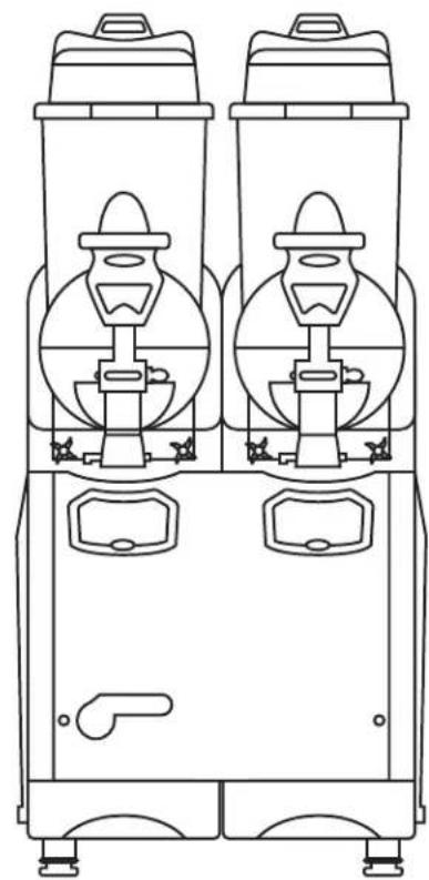
Line drawing of two identical industrial slurry machines with circular chambers and control knobs (no text or symbols)378SM262
DOUBLE BOWL
natural_image
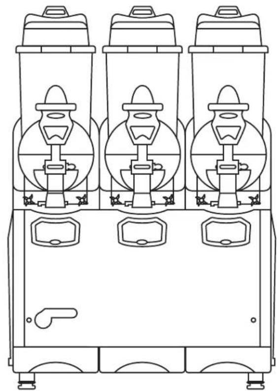
Line drawing of three identical industrial slippers with circular bases and side compartments (no text or symbols)378SM263
TRIPLE BOWL
TABLE OF CONTENTS
SAFETY 1
COMPONENTS, FEATURES & CONTROLS ..... 2
Main Components....2
Technical Features....2
Serial Plate 2
Main Control 2
Bowl Control 2
INSTALLATION 3
Unpacking 3
Positioning....3
Electrical Safety 3
Main Safety Information 3
OPERATION.... 4
Preparation....4
Slush Production 4
Thickness Control 4
Cold Drink Production 4
CLEANING 5
Disassembly 5
Washing & Sanitizing 6
Condenser Cleaning 6
Reassembly....7
Rinsing....8
REPLACEMENT....8
DISPOSAL....8
TROUBLESHOOTING 9
PARTS DIAGRAMS....10
ELECTRICAL DIAGRAMS 16
WARRANTY.... 17
SAFETY
- This instruction manual is an integral part of the machine and must be kept for any further consultation.
- This machine is a cold drink dispenser.
- This machine should be used only for the purpose for which it was designed. Any other use is inappropriate and therefore dangerous.
- The manufacturer will not be held responsible for any damage caused by improper use.
- Before installing and operating the machine, read this instruction manual carefully.
-
Basic safety rules:
-
DO NOT touch the machine when hands or feet are wet.
- DO NOT use the machine when barefoot.
- This appliance should only be used by persons who have the knowledge, experience,
and capability to operate it in a safe way. - DO NOT allow children to play with the appliance.
- DO NOT allow the machine to be used by children or untrained persons.
- DO NOT leave the machine outdoors.
- DO NOT pull on the electrical cord to unplug the machine.
COMPONENTS, FEATURES & CONTROLS
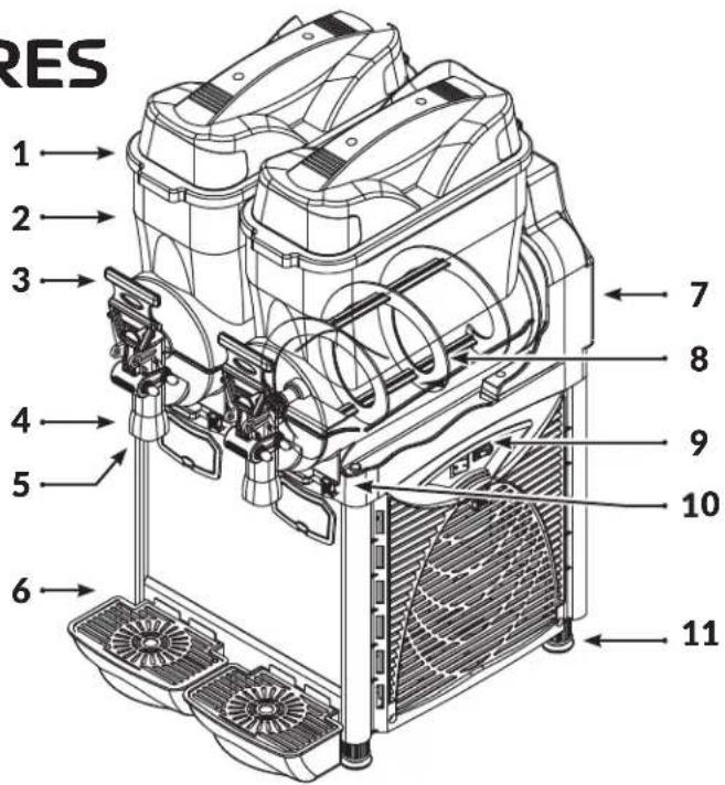
MAIN COMPONENTS
- Lid 7. Thickness Control
- Bowl 8. Spiral Blade
- Tap Lever 9. Main Switches
- Product Supply 10. Bowl Fixing Knob
- Bowl Switch Box 11. Rubber Leg
- Drip Tray
text_image
RES 1 2 3 4 5 6 7 8 9 10 11TECHNICAL FEATURES
| SM261 SM | M262 SM263 | ||
| Bowls 1 2 3 | |||
| Capacity 1 x 2.6 Gal 2 x 2.6 Gal 3 x 2.6 Gal | |||
| Gas R404a | |||
| Width 8.3 in 15.7 in 23.6 in | |||
| Depth | 20.8 in | ||
| Height | 33 in | ||
| Weight 70 lb | 123 lb | 158 lb | |
| Power | 530W | 850W | 1100W |
| Voltage | 120V | ||
| Acoustic Pressure | < 70 dB (A) | ||
| Class | N | ||
SERIAL PLATE
The technical features of the machine are reported on the serial plate attached on the frame.


ITEM #: 378SM261
MADE IN ITALY
MFR MODEL #: OASIS 1-10
SPECS: 1 x 2.6 GAL · 120V · 530W
GAS/Q.TY: R134a - Gr. 140
PRESSURE: HIGH - 186 PSI • LOW - 88 PSI
SERIAL #:
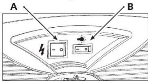
MAIN CONTROLS
Positioned on the right side of the machine.
text_image
A BA - Main Power Switch
0: Machine is OFF
I: Machine is ON
B - Lid Light Switch
0: Light is OFF
I: Light is ON
BOWL CONTROLS
Positioned underneath each bowl.

text_image
A C BA - Beverage Type Control Switch
0: Cooling OFF
I: Slush/Frozen Cream Mode
II: Cold Drink Mode
B - Spiral Blade Switch
0: Spiral Blade OFF
I: Spiral Blade ON
C - Thermostat Control
Controls the temperature of the product when the Beverage Type Control Switch is set to II.
INSTALLATION
UNPACKING
- Remove the carton box and the plastic bag.
- Make sure that the machine is intact and has not been damaged during transport.
- Dispose of any packaging materials properly, keep any that you may need for future moves.
POSITIONING
- Place the machine on a sturdy horizontal surface.
- For improved ventilation, maintain a distance of 10 in. between the unit and walls or other obstacles. Increase the distance if the obstacles are a heating source. (Fig. 1)
- Leave 60 in. of free space in front of the machine to allow for easy use and maintenance. (Fig. 1)
- Leave 10 in. of free space above the machine to allow for removal of lids. (Fig. 1)
- When the machine is in place, adjust the rubber legs to level.

text_image
60" 10" 10" 10" Fig. 1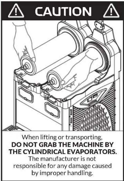
text_image
CAUTION When lifting or transporting, DO NOT GRAB THE MACHINE BY THE CYLINDRICAL EVAPORATORS. The manufacturer is not responsible for any damage caused by improper handling.ELECTRIC CONNECTION
If in doubt, consult a specialized electrical technician. Before inserting the plug into the electric outlet, carefully verify the following:
- Set the Main Power Switch to OFF (0).
- Verify that the machine is properly grounded.
- Verify the voltage of the outlet matches what is indicated on the serial plate.
- Verify the current available is sufficient for the maximum required by the machine.
- Inspect the cord for damage, if any is present DO NOT plug into the outlet.
- DO NOT use an extension cord or adapter to connect the machine to the electric supply.
MAIN SAFETY INFORMATION
• DO NOT touch the machine with wet hands or feet.
• DO NOT operate when barefoot.
- DO NOT allow the machine to be operated by children or untrained persons.
• DO NOT leave the machine outside.
- DO NOT pull the cable to disconnect the machine from the electric supply.
- DO NOT place the machine near flammable or explosive materials.
- DO NOT place the machine nearby any heat source or heating element.
OPERATION

CAUTION
Before using the machine, all food contact surfaces and components must be cleaned and sanitized in accordance to the Washing & Sanitizing section of this manual.
PREPARING THE PRODUCT
Concentrate
In order to obtain a homogeneous mix, the product will need to be pre-mixed before being added to the machine. Follow the manufacturer's recommendations for mixing.
Ready-to-Use & Pre-Mixed Concentrates
- Turn the machine OFF and unplug from power supply.
- Pour liquid into the bowl. (Fig. 2)
- DO NOT pour below the MIN Level.
- DO NOT pour above the MAX Level.
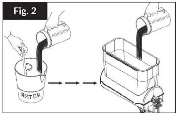
text_image
Fig. 2 WATERFROZEN BEVERAGES
In order to obtain a slush consistency, the mixture must have a minimum sugar content of 13^ BRIX (13g sugar to 100g solution). A lower concentration may damage the spiral blades and gear motors.
- Position the Beverage Type Control Switch to I (Slush/Frozen Cream Mode).
- Position the Spiral Blade Switch to I (ON).
- Wait for the mixture to freeze and test consistency. If consistency is good, continue to step 5. If not, continue to step 4.
- Thickness Control Knob is found behind the back panel of the machine. The machine is set for optimal slush thickness by the factory, turn the screw L to R to increase thickness, R to L to decrease thickness. (Fig. 3)
- Dispense the beverage by pulling the tap lever. (Fig. 5)

CAUTION
Over-icing and spiral blade jamming can be caused by the wrong thickness setting.
COLD DRINKS
Prepare the product separately before proceeding. It is recommended to maintain a product level above the cylinder evaporators for consistent cooling. (Fig. 4)
- Position the Beverage Type Control Switch to II (Cold Drink Mode).
- Position the Spiral Blade Switch to 0 (OFF).
- The optimal drink temperature has been set by the factory. Use the Thermostat Control to adjust the temperature of the drink.
- To set temperature, open the transparent screen on the front panel below the bowl and turn the Thermostat Screw.
- Dispense the beverage by pulling the tap lever. (Fig. 5)
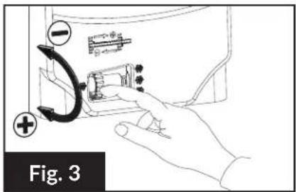
text_image
Fig. 3
natural_image
Technical line drawing of a mechanical device with internal components and housing (no text or symbols)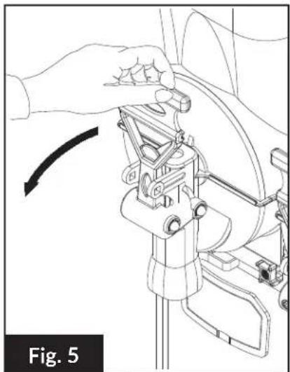
natural_image
Mechanical assembly diagram showing a hand adjusting a component with an arrow indicating rotation (no text or symbols present)CLEANING

CAUTION
The machine must be turned OFF and unplugged from the power source before cleaning.
EMPTY THE BOWL (Skip this step if this is the initial cleaning)
- Use the tap lever to empty any remaining liquid into a container.
- DO NOT proceed without emptying the bowl.
DISASSEMBLY
Dispensing Tap (Fig. 6)
- Place hand beneath the dispensing outlet to catch pieces as they are released.
- Pull the Lever Pin (A) to disconnect the Tap Valve (C) and Spring (D).
- If the Tap Lever (E) is to be washed, remove Lever Pin (B).
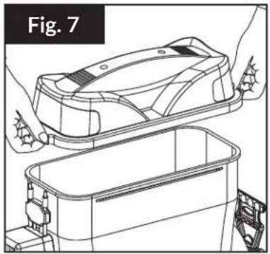
Lid (Fig. 7)
- Lift the lid straight upward to remove from the bowl.
natural_image
Line drawing of a car interior with hands installing or adjusting the lid panel (no text or symbols)
text_image
E B A C D Fig. 6Bowl (Fig. 8-12)
- Remove the (2) Front Fixing Knobs by unscrewing them counter-clockwise. (Fig. 8)
- Remove the bowl from its seat. (Fig. 9)
- Gently pull on the spiral blades to remove from the cylindrical evaporators. (Fig. 10)
- Gently pull on the Spiral Blade Gasket to remove. (Fig. 11)
- Gently pull on the Bowl Gasket to remove. (Fig. 12)

text_image
CAUTION When cleaning or lifting, DO NOT GRAB THE MACHINE BY THE CYLINDRICAL EVAPORATORS.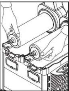
natural_image
Line drawing of hands operating a mechanical device with rollers and clamps (no text or symbols)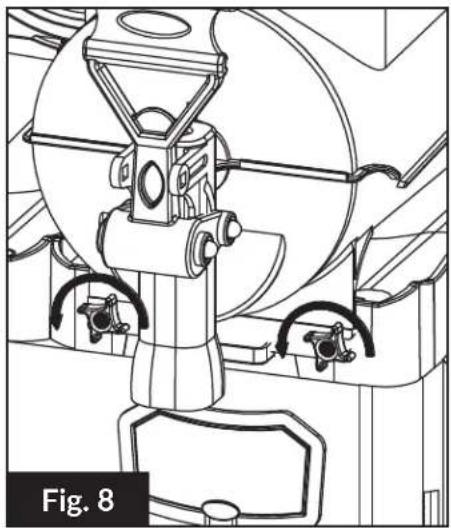
natural_image
Technical line drawing of a mechanical device with no visible text or symbols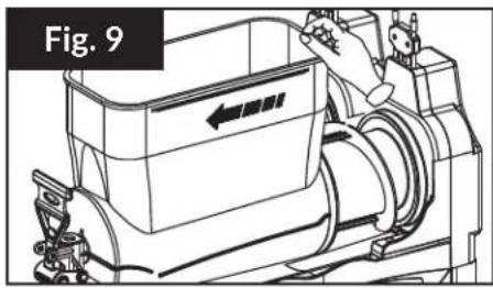
text_image
Fig. 9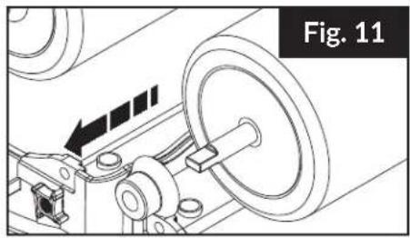
natural_image
Mechanical assembly diagram showing a rotating wheel and mechanical components (no text or symbols)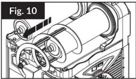
natural_image
Technical line drawing of a mechanical assembly (no text or symbols)
natural_image
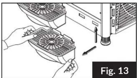
Mechanical assembly diagram showing a cylindrical component being inserted into a housing, with no visible text or symbols.Drip Tray (Fig. 13)
- Lift upward and then away from the machine to unseat the hooks.
- Wash with warm water and dry.
- Re-insert the hooks into their holes and push down.
natural_image
Illustration of hands installing or adjusting a fan-shaped component next to an air conditioner unit (no text or symbols visible)WASHING & SANITIZING
To maintain health standards and product quality, the machine must be cleaned daily. Failing to clean daily will void this warranty.

CAUTION
DO NOT wash any components of the machine in the dishwasher.
WASHING
- Fill a basin with lukewarm water (Approx. 104°F) and a neutral detergent suitable for plastic items.
- DO NOT use abrasive powders which might affect the bowl's transparency.
- Wash all components (except the lid) in the basin.
- DO NOT wash the lid by dipping in water. Doing so may damage electric components.
- Use a wet, soft cloth.
- Rinse all parts carefully with clean lukewarm water to remove any residual soap.
• Dry all parts with a soft cloth. - If the machine will not be in use for an extended period, cover and keep it away from dust.
SANITIZING
Sanitizing must be done before the initial use of the machine or if it is not used for an extended period of time.
- Follow washing instructions.
- Make a solution of lukewarm water (Approx. 104°F) and hypochlorite (bleach) with a 10g to 1L ratio.
- Use a soft cloth or brush to apply the solution to all components.
- Rinse all parts carefully with clean lukewarm water to remove any residual solution.
• Dry all parts with a soft cloth.
CONDENSER CLEANING
Regular maintenance of the condenser ensures the quality of the product and efficiency of the machine. This cleaning should be performed at least once a month.

CAUTION
The machine must be turned OFF and unplugged from the power source before cleaning.
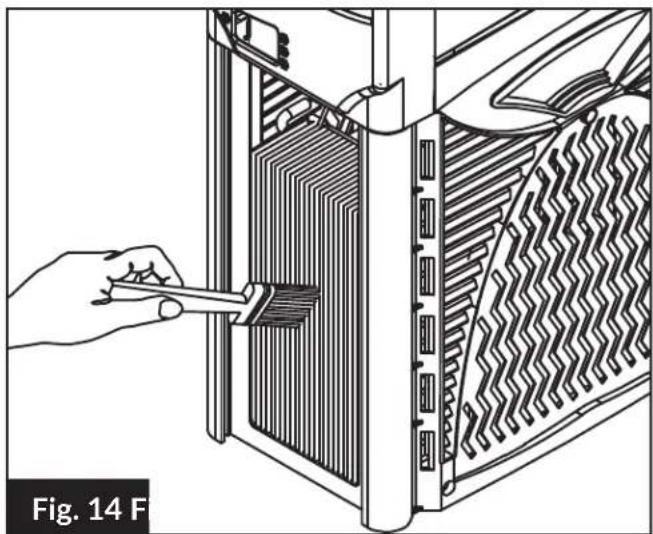
SM261 (Fig. 14) SM262 & SM263 (Fig. 15)
- Remove the back panel by unscrewing the 4 screws.
- Use a soft and dry brush to remove the dust from the condenser fins.
-
When cleaning is complete, replace the back panel with the 4 screws.
-
Remove the left side stainless steel panel by unscrewing the Fixing Knob (A) as shown.
- Use a soft and dry brush to remove the dust from the condenser fins.
- When cleaning is complete, replace the side panel with the Fixing Knob (A).
natural_image
Illustration of a hand using a tool to adjust or install a rack-mounted device into a server rack (no text or symbols visible)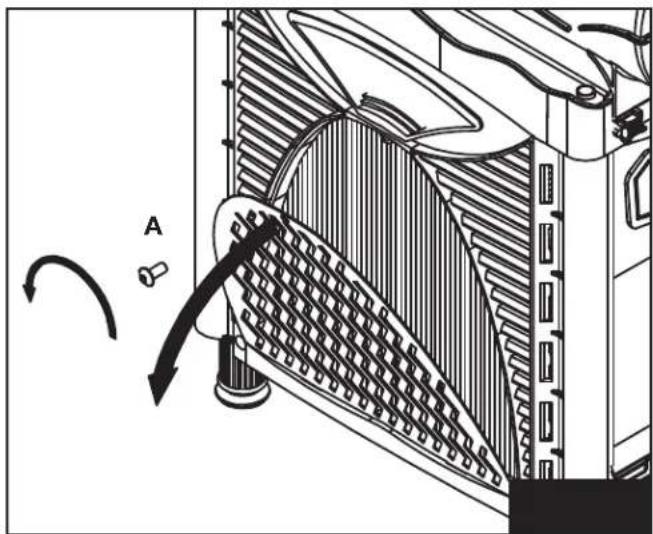
natural_image
Technical diagram of a heat exchanger with cooling fins and airflow direction indicator (no text or labels)REASSEMBLY
All washed and/or sanitized parts must be completely dry before being carefully reassembled. Some components must be lubricated in order to work efficiently. A tube of lube is included with each machine.
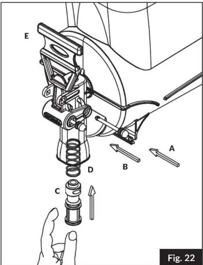
Dispensing Tap (Fig. 22)
- Place the Lever (E) in place so Pin (B) lines up correctly. Insert Pin (B) and secure.
- Lubricate the Tap Valve (C).
- Insert the Spring (D) into the product supply hole, followed by the lubricated Tap Valve (C) and secure with Pin (A).

text_image
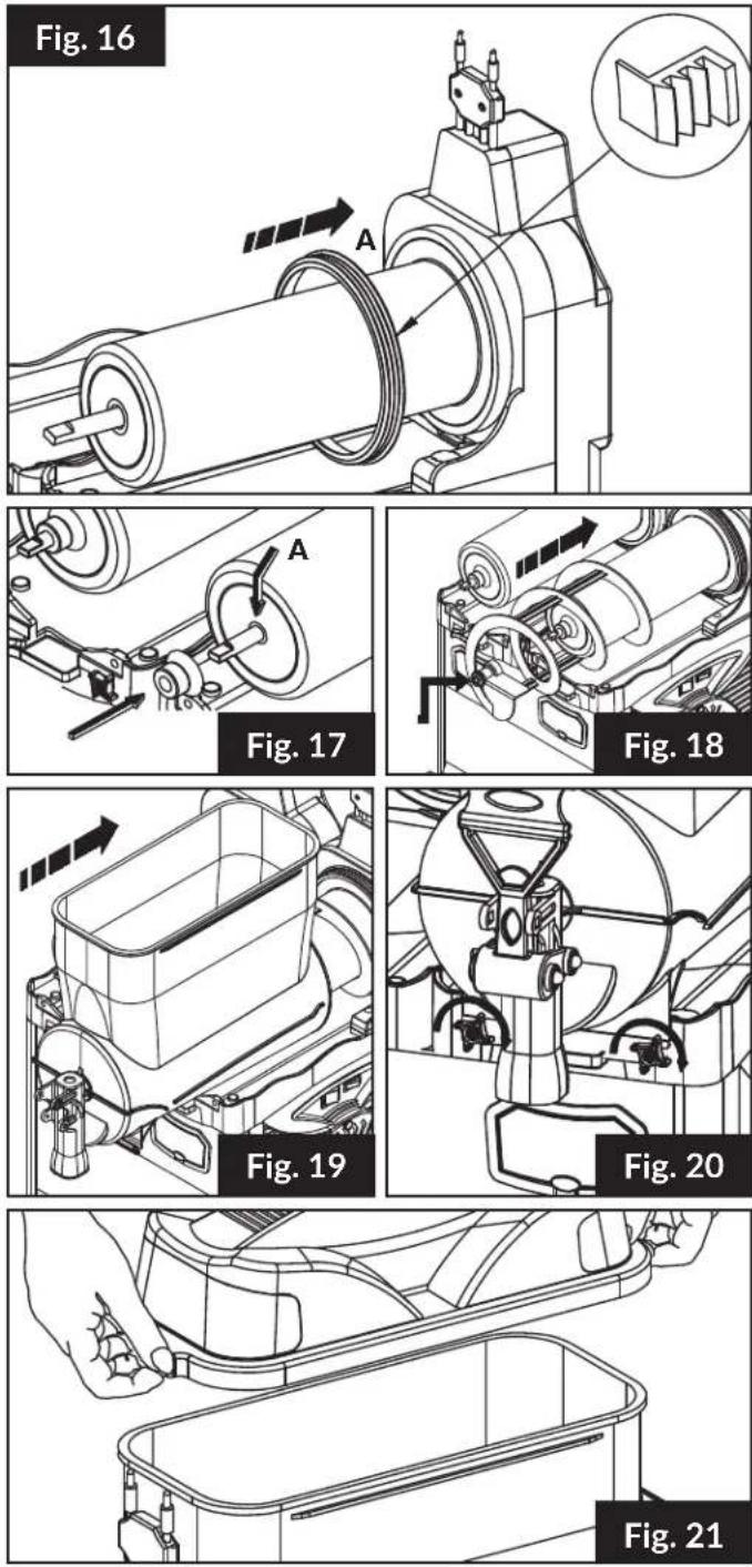
CAUTION When cleaning or lifting, DO NOT GRAB THE MACHINE BY THE CYLINDRICAL EVAPORATORS.Bowl (Fig. 16-20)
- Place the Bowl Gasket at the bottom of the Cylinder Evaporator, lubricating the upper part (A). (Fig. 16)
- Lubricate the surface of the cylinder in the zone of the transmission shaft outlet (A). (Fig. 17)
- Place the Spiral Blade Gasket (B), lubricating both the internal and external surfaces. (Fig. 17)
- Insert the Spiral Blade so that the head joins the transmission shaft. (Fig. 18)
- Lubricate the external part of the head of the Spiral Blade (A). (Fig. 18)
- After all bowl components are properly positioned and lubricated, slide the Bowl into position. (Fig. 19)
- Secure the bowl by screwing the Bowl Fixing Knobs clockwise. (Fig. 20)
Lid (Fig. 21)
- Place the lid over the bowl, verifying the correct insertion of the electric contacts.
text_image
E D B A C Fig. 22RINSE CYCLE
After cleaning, it is necessary to run a rinse cycle before loading product.
- Fill the bowl with clean water to the MAX Fill Line.
- Turn the Main Power Switch ON (I).
- Turn the Spiral Blade ON (I).
- Let the machine run for 5 minutes.
- Empty the bowl through the Dispensing Tap.
- Turn the Main Power Switch OFF (0).
- Use a soft towel to dry the inside of the bowl.
REPLACING THE LID LIGHT

CAUTION
The machine must be turned OFF and unplugged from the power source before maintaining.
- Remove the lid from the bowl. (Fig. 23)
- Unscrew the (2) top screws securing the top to the lid base.
- Replace the bulb only with a genuine spare part.
- Secure the top to the base with the (2) top screws.
- Reattach lid to bowl.

natural_image
Technical line drawing of a car interior with sensors and buttons (no text or symbols)Fig. 23
REPLACEMENT SCHEDULE
| CYCLE (MONTHS) ITEM | |
| 6 Replace bowl gasket | |
| 6 Replace spiral blade gasket | |
| 6 Inspect auger shaft for abnormal wear | |
| 6 Replace tap valve | |
| 6 Lubricate the motor shaft | |
| Monthly Clean condenser air filter | |
| 6 or as needed Clean condenser coil | |
| 6 or as needed Inspect and clean condenser fan | |
| 6 Inspect, clean or replace bowl drain tubes |
- Failing to perform required maintenance will void the warranty.
- Cleaning must be performed daily for optimal performance.
DISPOSAL
When the machine is no longer of use, dispose of it properly. Or if still operational, sell off through an authorized organization or company.
USEFUL INFORMATION
-
The cooling performance of the machine is influenced by:
-
External temperature
- Initial product temperature
- Sugar percentage in the product
-
Thickness/Temperature settings
-
In order to reduce startup time, it is strongly recommended that you not fill the bowl with warm or room temperature products. It is recommended to chill the product beforehand.
- When refilling or topping off a product, it is highly recommended that you chill the added product beforehand.
- If the product is a mixture of water and concentrate, it needs to be mixed before adding to the bowl.
TROUBLESHOOTING

CAUTION
Problems marked with this symbol must be handled by a specialized technician.
| PROBLEM CAUSE SOLUTION | ||
| The machine does not turn ON | The Main Switch is not set to I Set the Main Switch to I | |
| The machine is not plugged in Plug the machine into the outlet | ||
| Electric cable defective Replace the electric cable | ! | |
| The Main Switch is defective Replace the switch | ! | |
| The machine does not make the product into slush | The Spiral Blade Switch is set to 0 Set the Spiral Blade Switch to I | |
| The Beverage Type Control Switch is not set to I Set the Beverage Type Control Switch to I | ||
| Product has too high of a sugar content Remove product and dilute in a separate container | ||
| Wrong Thickness Control setting Set Thickness Control correctly (see Fig. 3) | ||
| Insufficient ventilation or nearby heat source | Move the machine so it has adequate ventilation and is far away from heat sources (see Fig. 1) | |
| Leaking refrigerant Restore and re-charge the cooling system | ! | |
| Dust accumulation on condenser | Clean the condenser (see Fig. 14/15) | |
| The micro-switch of the Thickness Control is defective | Clean or replace the micro-switch | |
| The Spiral Blade does not turn | Spiral Blade Switch set to 0 | Set Spiral Blade Switch to I |
| Ice accumulation in bowl | Switch the Main Switch OFF and wait for ice to melt | |
| Spiral Blade Switch is defective | Replace the Spiral Blade Switch | |
| The Spiral Blade makes noise | Insufficient lubrication | Lubricate all areas correctly (see Fig. 16-18) |
| Dispensing Tap is leaking | Dispensing Tap Valve (C) is defective | Replace the Tap Valve (C) |
| Insufficient lubrication | Lubricate Tap Valve (C) correctly (see Fig. 22) | |
| Dispensing Tap does not dispense product | Ice accumulation in bowl | Switch the Main Switch OFF and wait for ice to melt |
text_image
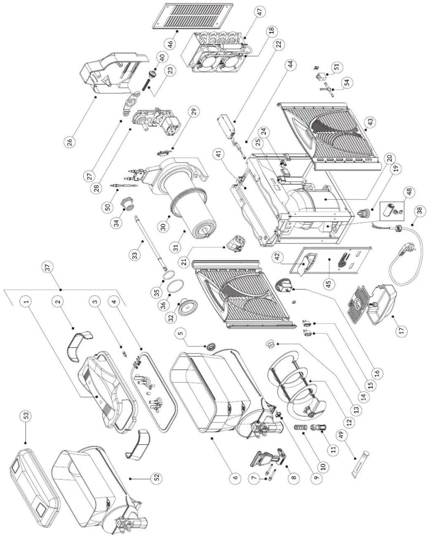
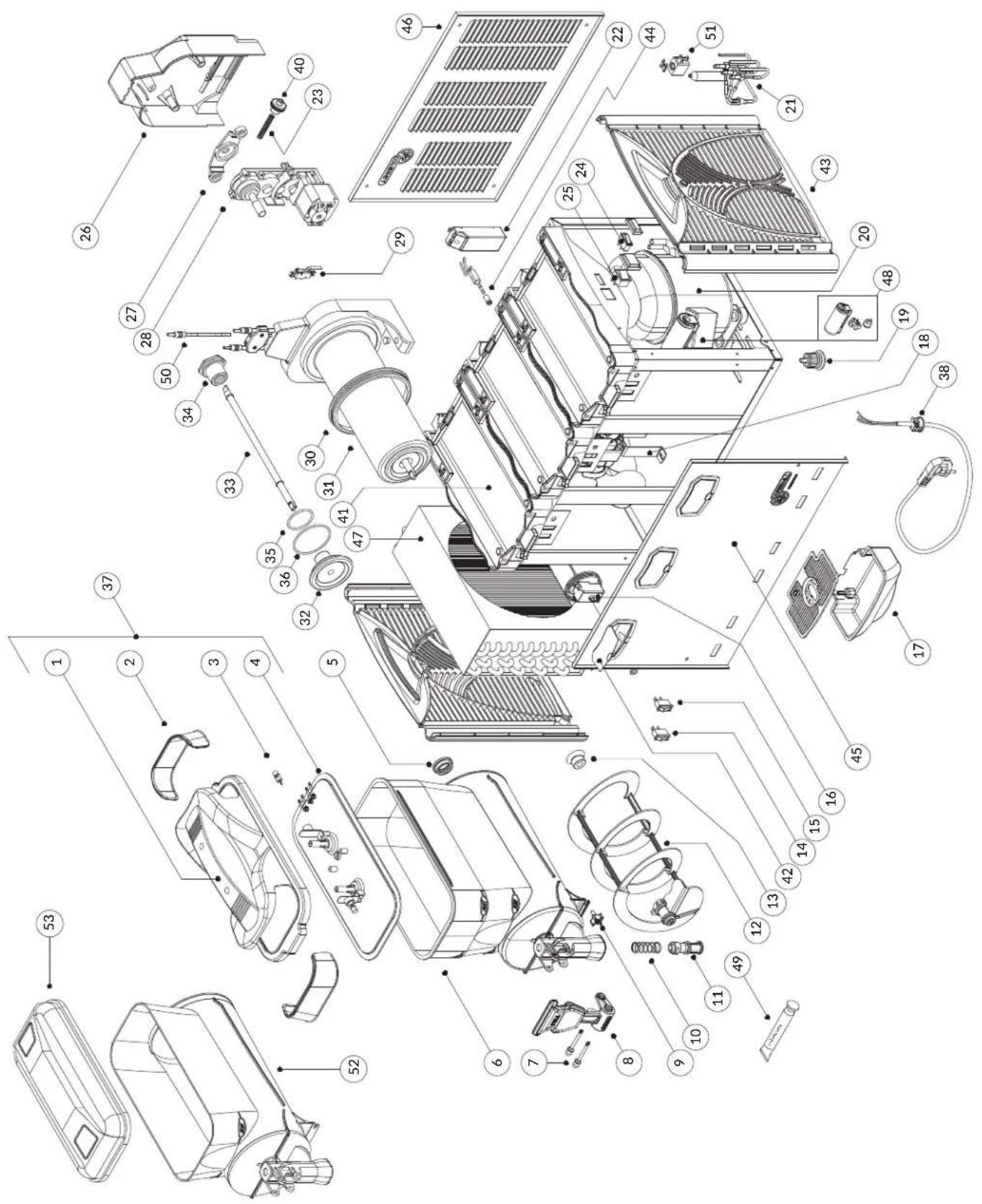
Exploded view diagram of a refrigerator internal components with numbered labels for identification.PARTS DIAGRAM - SM261
| NO. CODE DESCRIPTION | ||
| 1 2107 | Lid | |
| 2 2122 | Screen for lid | |
| 3 2158 | 12V-3W lamp led | |
| 4 2127 | Under-lid | |
| 5 2112 | Spiral blade | |
| 6 2133 | Bowl Oasis | 10Lt |
| 7 2150 | Rotation pin | |
| 8 2117 | Tap lever | |
| 9 2149 | Fixing knob | |
| 10 2120 | Tap spring | |
| 11 2134 | Tap valve | |
| 12 2113 | Spiral blade | |
| 13 2115 | Spiral blade gasket | |
| 14 2137 | Slush/Drink switch | |
| 15 56 | Spiral blade switch | |
| 16 2160 | Thermostat | |
| 17 2161 | Complete drip tray | |
| 18 | 182 Fan motor 220-240V - 50/60Hz | |
| 68 Fan motor 115V - 60Hz | ||
| 19 0159 | Rubber leg H=35 | |
| 20 | 2164 Compressor 220-240V-50Hz | |
| 2165 Compressor 115V-60Hz | ||
| 21 | 2162 Timer 220V (4 min) | |
| 2163 Timer 115V (4min) | ||
| 22 | 2166 Transformer 220-240V - 50Hz | |
| 2167 Transformer 115V - 60Hz | ||
| 23 2157 | Thickness control spring | |
| 24 56 | Light switch | |
| 25 57 | Main switch | |
| 26 2108 | Back support cover | |
| 27 2131 | Motor-gearbox support | |
| 28 2121 | Motor-gearbox 220/115V-50/60hz | |
| NO. CODE DESCRIPTION | ||
| 29 216 | 8 Micro-switch | |
| 30 211 | 6 Bowl gasket | |
| 31 211 | 0 Evaporator | |
| 32 214 | 5 Evaporator cover | |
| 33 210 | 1 Transmission shaft | |
| 34 211 | 1 Metal ring M25 | |
| 35 212 | 3 Evaporator cover inner OR (small) | |
| 36 154 | Evaporator cover inner OR (large) | |
| 37 215 | 9 Complete lid | |
| 38 | 54 Cable cord 220V | |
| 407 Cable cord 115V | ||
| 40 216 | 9 Thickness control knob | |
| 41 212 | 5 Evaporator plate | |
| 42 212 | 6 Switches box | |
| 43 214 | 8 Side panel | |
| 44 217 | 2 Fuse | |
| 45 222 | 0 Front panel | |
| 46 217 | 4 Back panel | |
| 47 217 | 5,01 Condenser | |
| 48 | 2164,01 Electric parts kit 220-240V-50Hz | |
| 2165,01 Electric parts kit 115V-60Hz | ||
| 49 211 | 8 Lubricant tube | |
| 50 210 | 3 Electric contact shaft | |
| 52 213 | 3,01 Bowl Kream line 6 Lt | |
| 53 210 | 7,02 Kream line lid | |

text_image
Exploded view diagram of a refrigerator internal components with numbered labels for identification.PARTS DIAGRAM - SM262
| NO. CODE DESCRIPTION | ||
| 1 2107 | Lid | |
| 2 2122 | Screen for lid | |
| 3 2158 | 12V-3W lamp led | |
| 4 2127 | Under-lid | |
| 5 2112 | Spiral blade | |
| 6 2133 | Bowl Oasis | 10Lt |
| 7 2150 | Rotation pin | |
| 8 2117 | Tap lever | |
| 9 2149 | Fixing knob | |
| 10 2120 | Tap spring | |
| 11 2134 | Tap valve | |
| 12 2113 | Spiral blade | |
| 13 2115 | Spiral blade gasket | |
| 14 2137 | Slush/Drink switch | |
| 15 56 | Spiral blade switch | |
| 16 2160 | Thermostat | |
| 17 2161 | Complete drip tray | |
| 18 | 2138 Fan motor 220-240V - 50/60Hz | |
| 2208 Fan motor 115V - 60Hz | ||
| 19 2153 | Rubber leg H=35 | |
| 20 | 2186 Compressor 220-240V-50Hz | |
| 2187 Compressor 115V-60Hz | ||
| 21 | 2143 Electrovalve complete 220V | |
| 2184 Electrovalve complete 115V | ||
| 22 | 2166 Transformer 220-240V - 50Hz | |
| 2167 Transformer 115V - 60Hz | ||
| 23 2157 | Thickness control spring | |
| 24 56 | Light switch | |
| 25 57 | Main switch | |
| 26 2108 | Back support cover | |
| 27 2131 | Motor-gearbox support | |
| 28 2121 | Motor-gearbox 220/115V-50/60hz | |
| NO. CODE DESCRIPTION | ||
| 29 216 | 8 Micro-switch | |
| 30 211 | 6 Bowl gasket | |
| 31 211 | 0 Evaporator | |
| 32 214 | 5 Evaporator cover | |
| 33 210 | 1 Transmission shaft | |
| 34 211 | 1 Metal ring M25 | |
| 35 212 | 3 Evaporator cover inner OR (small) | |
| 36 154 | Evaporator cover inner OR (large) | |
| 37 215 | 9 Complete lid | |
| 38 | 54 Cable cord 220V | |
| 407 Cable cord 115V | ||
| 40 216 | 9 Thickness control knob | |
| 41 212 | 5 Evaporator plate | |
| 42 212 | 6 Switches box | |
| 43 214 | 8 Side panel | |
| 44 217 | 2 Fuse | |
| 45 222 | 0 Front panel | |
| 46 217 | 4,01 Back panel | |
| 47 214 | 6,01 Condenser | |
| 48 | 2186,01 Electric parts kit 220-240V-50Hz | |
| 2187,01 Electric parts kit 115V-60Hz | ||
| 49 211 | 8 Lubricant tube | |
| 50 210 | 3 Electric contact shaft | |
| 51 | 2105 Coil 220V - 50/60 Hz | |
| 2183 Coil 115V - 50/60 Hz | ||
| 52 213 | 3,01 Bowl Kream line 6 Lt | |
| 53 210 | 7,02 Kream line lid | |
text_image
Exploded view diagram of a refrigerator internal components with numbered labels for identification.PARTS DIAGRAM - SM263
| NO. CODE DESCRIPTION | ||
| 1 2107 | Lid | |
| 2 2122 | Screen for lid | |
| 3 2158 | 12V-3W lamp led | |
| 4 2127 | Under-lid | |
| 5 2112 | Spiral blade | |
| 6 2133 | Bowl Oasis | 10Lt |
| 7 2150 | Rotation pin | |
| 8 2117 | Tap lever | |
| 9 2149 | Fixing knob | |
| 10 2120 | Tap spring | |
| 11 2134 | Tap valve | |
| 12 2113 | Spiral blade | |
| 13 2115 | Spiral blade gasket | |
| 14 2137 | Slush/Drink switch | |
| 15 56 | Spiral blade switch | |
| 16 2160 | Thermostat | |
| 17 2161 | Complete drip tray | |
| 18 | 2139 Fan motor 220-240V - 50/60Hz | |
| 2218 Fan motor 115V - 60Hz | ||
| 19 2153 | Rubber leg H=35 | |
| 20 | 2188 Compressor 220-240V-50Hz | |
| 2189 Compressor 115V-60Hz | ||
| 21 | 2144 Electrovalve complete 220V | |
| 2144,01 Electrovalve complete 115V | ||
| 22 | 2166 Transformer 220-240V - 50Hz | |
| 2167 Transformer 115V - 60Hz | ||
| 23 2157 | Thickness control spring | |
| 24 56 | Light switch | |
| 25 57 | Main switch | |
| 26 2108 | Back support cover | |
| 27 2131 | Motor-gearbox support | |
| 28 2121 | Motor-gearbox 220/115V-50/60hz | |
| NO. CODE DESCRIPTION | ||
| 29 216 | 8 Micro-switch | |
| 30 211 | 6 Bowl gasket | |
| 31 211 | 0 Evaporator | |
| 32 214 | 5 Evaporator cover | |
| 33 210 | 1 Transmission shaft | |
| 34 211 | 1 Metal ring M25 | |
| 35 212 | 3 Evaporator cover inner OR (small) | |
| 36 154 | Evaporator cover inner OR (large) | |
| 37 215 | 9 Complete lid | |
| 38 | 54 Cable cord 220V | |
| 407 Cable cord 115V | ||
| 40 216 | 9 Thickness control knob | |
| 41 212 | 5 Evaporator plate | |
| 42 212 | 6 Switches box | |
| 43 214 | 8 Side panel | |
| 44 217 | 2 Fuse | |
| 45 222 | 0,02 Front panel | |
| 46 217 | 4,02 Back panel | |
| 47 214 | 6,02 Condenser | |
| 48 | 2188,01 Electric parts kit 220-240V-50Hz | |
| 2189,01 Electric parts kit 115V-60Hz | ||
| 49 211 | 8 Lubricant tube | |
| 50 210 | 3 Electric contact shaft | |
| 51 | 2105 Coil 220V - 50/60 Hz | |
| 2183 Coil 115V - 50/60 Hz | ||
| 52 213 | 3,01 Bowl Kream line 6 Lt | |
| 53 210 | 7,02 Kream line lid | |
ELECTRICAL DIAGRAMS
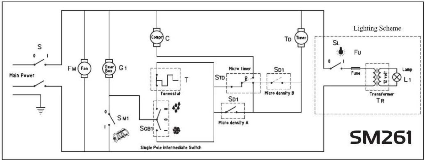
flowchart
graph TD
    A["Main Power"] --> B["S"]
    B --> C["FM Fan"]
    C --> D["Gear Box G1"]
    D --> E["SM1 SGB1"]
    E --> F["Single Pole intermediate Switch"]
    F --> G["Compr C"]
    G --> H["Td Timer"]
    H --> I["Lighting Scheme"]
    I --> J["SL FU Fuse"]
    J --> K["Transformer TR 12 volt Lamp L1"]
    K --> L["Lamp L1"]
    F --> M["Micro density A"]
    F --> N["Micro density B"]
    F --> O["Termostat T"]
    F --> P["Std STD Micro Timer"]
    F --> Q["SD1 SD1 Micro density"]

flowchart
graph TD
    A["Main Power"] --> B["S"]
    B --> C["FM Fan"]
    C --> D["C Compr"]
    D --> E["G1 Gear Box"]
    E --> F["T1 Termostat"]
    F --> G["SD1 Electro valve EV1"]
    G --> H["Electro valve EV1"]
    I["SM1"] --> J["SGB1"]
    K["SM2"] --> L["SGB2"]
    M["SL"] --> N["Fuse"]
    N --> O["Lamp"]
    P["Transformer TR"] --> Q["L1"]
    P --> R["L2"]
    S["Lighting Scheme"] --> T["Switch S"]
    U["SM262"] --> V["Switch SL"]
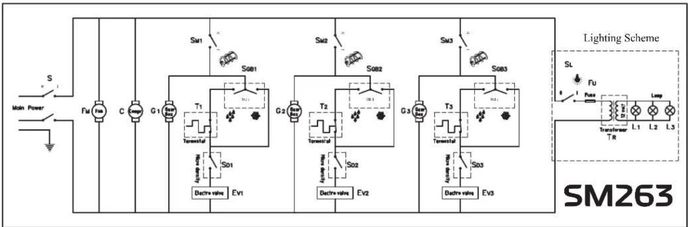
flowchart
graph TD
    A["Main Power"] --> B["S"]
    B --> C["Fin"]
    C --> D["C"]
    D --> E["G1"]
    E --> F["Switch S01"]
    F --> G["Tanestal"]
    G --> H["Switch S02"]
    H --> I["Bachre valve EV1"]
    J["Switch S081"] --> K["Tanestal"]
    L["Switch S082"] --> M["Tanestal"]
    N["Switch S083"] --> O["Tanestal"]
    P["Switch S081"] --> Q["Tanestal"]
    R["Switch S082"] --> S["Tanestal"]
    T["Switch S083"] --> U["Tanestal"]
    V["Switch S081"] --> W["Tanestal"]
    X["Switch S082"] --> Y["Tanestal"]
    Z["Switch S083"] --> AA["Tanestal"]
    AB["Switch S081"] --> AC["Tanestal"]
    AD["Switch S082"] --> AE["Tanestal"]
    AF["Switch S083"] --> AG["Tanestal"]
    AH["Switch S081"] --> AI["Tanestal"]
    AJ["Switch S082"] --> AK["Tanestal"]
    AL["Switch S083"] --> AM["Tanestal"]
    AN["Switch S081"] --> AO["Tanestal"]
    AP["Switch S082"] --> AQ["Tanestal"]
    AR["Switch S083"] --> AS["Tanestal"]
    AT["Switch S081"] --> AU["Tanestal"]
    AV["Switch S082"] --> AW["Tanestal"]
    AX["Switch S083"] --> AY["Tanestal"]
    AZ["Switch S081"] --> BA["Tanestal"]
    BB["Switch S082"] --> BC["Tanestal"]
    BD["Switch S083"] --> BE["Tanestal"]
    BF["Switch S081"] --> BG["Tanestal"]
    BH["Switch S082"] --> BI["Tanestal"]
    BJ["Switch S083"] --> BK["Tanestal"]
    BL["Switch S081"] --> BM["Tanestal"]
    BN["Switch S082"] --> BO["Tanestal"]
    BP["Switch S083"] --> BQ["Tanestal"]
    BR["Switch S081"] --> BS["Tanestal"]
    BT["Switch S082"] --> BU["Tanestal"]
    BV["Switch S083"] --> BW["Tanestal"]
| S Main power switch |
| G 1,2,3 Motor-gearbox |
| FM Fan motor |
| C Compressor |
| T 1,2,3 Drink thermostat |
| SD 1,2,3 Thickness micro-switch | |
| EV 1,2,3 Electrovalve | |
| TR | Transformer |
| L 1,2,3 | Light |
| SM 1,2,3 | Spiral blade switch |
| SGB 1,2,3 | Slush/drink switch |
| TD | Timer |
| FU | Fuse |
| SL | Light Switch |
EQUIPMENT LIMITED WARRANTY
1 Year Parts and Labor Warranty
Unless otherwise stated, Narvon Beverage Equipment warrants to the original purchaser of new Narvon beverage dispensers and slushy machines, that such equipment will be free from defects in material and workmanship for a period of 1 year from the original date of delivery. Valid only in the Contiguous United States. The 1 year parts and labor warranty applies to only the following models.
378D5G3, 378SM261, 378SM262, 378SM263, 378SMM2B
1 Year Replacement Warranty
Unless otherwise stated, Narvon Beverage Equipment warrants to the original purchaser of new Narvon beverage dispensers and slushy machines, that such equipment will be free from defects in material and workmanship for a period of 1 year from the original date of delivery. Valid only in the Contiguous United States. The 1 year replacement warranty applies to only the following models.
378D5G1, 378SMM1B, 378D5G2
What This Warranty Does Not Cover
- Narvon Beverage Equipment will not warrant coverage for component failure or other damages that arise under the following conditions:
- Failure to install and/or use the unit within proper operating conditions specified by Narvon. This includes installation in any and all outdoor or mobile applications.
- Failure to properly maintain the unit. This includes, but is not limited to, basic preventative maintenance like cleaning. It is the operator's responsibility to clean the unit.
- Installation in non-commercial or residential applications. Because Narvon is a commercial brand intended to be installed in a commercial setting, units installed in a residence are not covered under warranty. Contact your authorized dealer for assistance.
• Products sold or used outside of the Contiguous United States.
• Any damage that occurs as a result of negligence or improper handling. - Additionally, no claims can be made against this warranty for spoilage of products, loss of sales or profits, or any other consequential damages. Normal wear type parts, are not included in warranty coverage
Any action for breach of this warranty must be commenced within 6 months of the date on which the breach occurred. No modification of this warranty, or waiver of its terms, shall be effective unless approved in a writing signed by the parties. The laws of the Commonwealth of Pennsylvania shall govern this warranty and the parties' rights and duties under it. Narvon shall not under any circumstances be liable for incidental or consequential damages of any kind, including but not limited to loss of profits.
For Warranty Inquiries or Service
This warranty is only valid on equipment purchased from an authorized dealer. To make a claim please contact Ready Kitchen Warranty.
Phone: 717-381-4844
- Please have your model number, serial number, proof of purchase, and proof of qualified installation ready before calling.
Email: help@readykitchenwarranty.com
- Please include your name, model number, serial number, proof of purchase, proof of installation, and a brief description of the issue in your email. Including clear pictures of the issue will help expedite the process. Failure to include one or more of these things will extend processing time.
Food Truck and Outdoor Commercial Use Warranty
Valid only in the Contiguous United States
Narvon Beverage Equipment warrants new equipment sold to food trucks and commercial customers that have installed the unit outdoors to be operational upon delivery and proper installation, not to exceed a period of 30 days from the date of delivery. Food Trucks must be located at a permanent address with the unit easily accessible for service. Outdoor use must be covered and installed in a permanent outdoor kitchen, bar, or service area. This warranty does not cover issues caused by a lack of ventilation, overheating, inconsistent voltage/power supply, or excessive humidity. Contact your authorized place of purchase for assistance.