VSC6818-4.8 - Software Microchip - Free user manual and instructions
Find the device manual for free VSC6818-4.8 Microchip in PDF.

User questions about VSC6818-4.8 Microchip
0 question about this device. Answer the ones you know or ask your own.
Ask a new question about this device
Download the instructions for your Software in PDF format for free! Find your manual VSC6818-4.8 - Microchip and take your electronic device back in hand. On this page are published all the documents necessary for the use of your device. VSC6818-4.8 by Microchip.
USER MANUAL VSC6818-4.8 Microchip
2.1 Supported Switch Plaorms....11
2.2 Soware Architecture....13
3 Supported Features....14
3.1 BSP and API....14
3.2 Port Control....14
3.3 Quality of Service (QoS)....15
3.4 L2 Switching....16
3.5 Protecon....18
3.6 L3 Switching....19
3.7 Security....20
3.8 Timing and Synchronizaon....21
3.9 Carrier Ethernet (OAM and Tesng)....22
3.10 Robustness and Power Savings....24
3.11 Customizaon Framework....26
3.12 Management....26
3.13 SNMP MIBs....28
4 Features and Plaorm Capacity....30
5 System Requirements....34
6 Port and System Capabilities....36
6.1 Port Capability....36
6.2 System Capability....36
7 Firmware Upgrade....37
8 Port Control....38
8.1 NPI Port....38
8.2 PCIe....38
8.3 Dual CPU (Applicaon Variant with JSON)....38
8.4 SFP Detecon....38
8.5 VeriPHY Support....38
8.6 PoE/PoE+ Support....38
8.7 POE/POE+ with LLDP....38
8.8 Unidireconal Link Detecon (UDLD)....38
9 Quality of Service (QoS)....40
9.1 Port Policers....40
9.2 Scheduling and Shaping....40
9.3 QCL Configuraon....40
9.4 Weighted Random Early Detecon (WRED)....40
9.5 Tag Remarking....40
9.6 Ingress Port Classificaon....41
9.7 Queue Policers....41
9.8 HQoS....41
9.9 DiServ (RFC2474) Remarking....41
9.10 Global Storm Control....42
10 L2 Switching....43
10.1 Virtual LAN....43
10.1.1 Voice VLAN....43
10.1.2 Private VLAN, Port Isolaon....44
10.1.3 MAC-Based, Protocol-Based, and IP Subnet-Based VLAN....44
10.1.4 Auto MAC Address Learning/Aging....44
10.1.5 MAC Addresses-Stac....44
10.2 Industrial Private VLANs....44
10.3 Generic VLAN Registraon Protocol (GVRP)....45
10.4 VLAN Translaon....45
10.5 Mulple Registraon Protocol (MRP)....45
10.6 Mulple VLAN Registraon Protocol (MVRP)....45
10.7 IEEE 802.3ad Link Aggregaon....45
10.7.1 Stac....46
10.7.2 Link Aggregaon Control Protocol (LACP)....46
10.8 Bridge Protocol Data Unit (BPDU) Guard, Restricted Role, and Error Disable Recovery.
10.9 DHCP Snooping....46
10.10 MAC Table Configuraon....46
10.11 Mirroring (SPAN/VSPAN and RSPAN)....47
10.12 RMirror....47
10.13 Flow Mirroring for AC....47
10.14 Spanning Tree....47
10.15 Loop Guard....47
10.16 L2 Mulcast....48
10.16.1 IP Mulcast (IPMC) Profile Configuraon....48
10.16.2 IGMP Snooping and MLD Snooping....48
10.16.3 Mulcast VLAN Registraon (MVR)....48
10.16.4 Filtering (IGMP Snooping and MLD Snooping)....48
11 Protecon....49
11.1 Ethernet Ring Protecon (ERP)....49
11.1.1 G.8032 Ring Protecon v.1 and v.2....49
near Protecon using Ethernet Protecon Switching (EPS)....49
11.2.1 1:1 Port Protecon....49
11.2.2 1:N Port Protecon....50
12 L3 Switching....51
12.1 Universal Plug and Play (UPnP)....51
12.2 DHCP Relay....51
12.3 L3 Roung....51
13 Security....52
13.1 802.1X and MAC-Based Authencaon....52
13.2 Port Security....53
13.3 Authencaon, Authorizaon, and Accoung (AAA)....53
13.4 Secure Access....54
13.5 Users and Privilege Levels....54
13.6 Authencaon and Authorizaon Methods....54
13.6.1 Authencaon Method....54
13.6.2 Command Authorizaon Method Configuraon....55
13.6.3 Accounting Method Configuraon....55
13.6.4 Management Access Filtering....55
13.7 Access Control List (ACLs)....55
13.8 ARP Inspecon/IP and IPv6 Source Guard....56
13.8.1 Guest VLAN....56
14 Timing and Synchronizaon....57
14.1 SyncE....57
14.2 Precision Time Protocol (PTP)....58
14.3 14.3 G.8265.1 BMCA....58
14.4 PTP Profile....59
14.5 Clock Quality....59
14.6 G.8275 Compliant Filter....59
14.7 PTP Time Interface....59
14.8 Network Time Protocol (NTP)....59
14.9 Microsemi One-step TC PHY Soluon....59
14.9.1 Peer-to-Peer Transparent Clock....59
14.9.2 End-to-End Transparent Clock....59
14.9.3 Boundary Clock....59
14.9.4 PTP over IPv4....59
14.9.5 Unicast/Mulcast....59
15 Carrier Ethernet (OAM and Tesng)....60
15.1 Ethernet Services....60
15.1.1 MEF....60
15.1.2 Provider Bridging....61
15.1.3 Proprietary Features....61
15.1.4 L2CP Tunneling....61
15.2 OAM....62
15.2.1 Link OAM (802.3ah)....62
15.2.2 Dying Gasp....63
15.2.3 Flow OAM....63
15.3 IEEE 802.1ag Support....63
15.4 ITU-T Support....63
15.5 Syslog Support....64
15.5.1 AIS Syslogs....64
15.5.2 MIB Alarm Syslogs....64
15.6 RFC2544 Support....64
15.7 Performance Monitoring (PM)....64
15.8 Traffic Test Loop....65
15.9 Y.1564 (SAM) Support....65
15.10 Mulprotocol Label Switching-Transport Profile (MPLS- TP) Support....66
15.10.1 MEF CE 2.0 E-LINE Delivery over MPLS-TP Pseudowire....66
15.10.2 MEF CE 2.0 E-LAN Delivery over H-VPLS....66
15.10.3 Pseudowire Label Edge Router (LER) Features....66
15.10.4 Label-Switched Path (LSP) Support....66
15.10.5 MPLS-TP OAM....67
15.10.6 MPLS-TP (1:1 Linear) Protecon....67
15.10.7 QoS....67
16 Robustness and Power Savings....69
16.1 Robustness....69
16.1.1 Cold and Cool Restart....69
16.2 Power Savings....69
16.2.1 Energy-Efficient Ethernet (EEE) Support....69
16.2.2 LED Power Reducon Support....69
16.2.3 Adapve Fan Control....69
16.3 AcPHY....69
16.3.1 Thermal Protecon....70
16.4 PerfectReach....70
17 Management....71
17.1 JSON-RPC....71
17.1.1 JSON-RPC Noficaons....71
17.2 Management Services....71
17.2.1 Industry Standard CLI Model....72
17.2.1.1 User EXEC Mode....72
17.2.1.2 Privileged EXEC Mode....73
17.2.2 Industry Standard Configuraon Support....73
17.2.3 Web....74
17.3 Simple Network Management Protocol (SNMP)....74
17.4 RMON Stascs....74
17.5 Internet Control Message Protocol....75
17.6 SysLog....75
17.7 LLDP-MED....75
17.8 802.1AB LLDP and CDP Aware....77
17.8.1 CDP Awareness....77
17.9 IP Management, DNS, and DHCPv4/v6....78
17.10 IPv6 Ready Logo Phase2....78
17.11 DHCP Server....79
17.12 Console....79
17.13 System Management....79
17.14 Crash File Support....79
17.15 Management Access Filtering....79
17.16 sFlow....79
17.17 Default Configuraon....79
17.18 Configuraon Upload/Download....80
17.19 Loop Detecon Restore toDefault....80
17.20 Daylight Saving....80
17.21 Symbolic Register Access....80
17.22 SD/MMC Card Slot....80
18 SNMPMIBs....81
18.1 Private MIBs....81
Figures
Figure 1 • Applicaon Architecture....13
Tables
Table 1 • Supported Switches ....11
Table 2 • Supported 1G PHYs .....11
Table 3 • Supported 10G PHYs .....12
Table 4 • BSP and API: Supported Features ....14
Table 5 • Port Control: Supported Features ....14
Table 6 • QoS: Supported Features ....15
Table 7 • L2 Switching: Supported Features ....16
Table 8 • Protecon: Supported Features ....19
Table 9 • L3 Switching: Supported Features ....19
Table 10 • Security: Supported Features ....20
Table 11 • Timing and Synchronizaon: Supported Features ......21
Table 12 • Carrier Ethernet (OAM and Tesng): Supported Features ....22
Table 13 • Robustness and Power Savings: Supported Features ....25
Table 14 • Customizaon Framework: Supported Features ....26
Table 15 • Management: Supported Features 26
Table 16 • SNMP MIBs: Supported Features ....28
Table 17 • Features and Plaorm Capacity ....30
Table 18 • Port System Requirements ....34
Table 19 • Hardware System Requirements ....34
Table 20 • DHCP Relay Configuraon Parameters ....51
Table 21 • Secure Access Opons ....54
Table 22 • ifIndex Descripons ....81
1 Revision History
| Details of ChangeRevision DateRevision | |
| May 20191.8 | Revision 1.8 was published in May 2019 to align with the Linux applicaon soware release 4.8 following is a summary of changes in revision 1.8 of this document.The Port Control: Supported Features table was updated. For more informaon, see 5 • Port Control: Supported Features.The Security: Supported Features table was updated. For more informaon, see Table Security: Supported Features.The Management: Supported Features table was updated. For more informaon, see 15 • Management: Supported Features. |
| January 20191.9 | Revision 1.7 was published in January 2019 to align with the Linux applicaon soware release following is a summary of changes in revision 1.7 of this document.The BSP and API: Supported Features table was updated. For more informaon, see 4 • BSP and API: Supported Features.The QoS: Supported Features table was updated. For more informaon, see Table 6 Supported Features.The L3 Switching: Supported Features table was updated. For more informaon, see 9 • L3 Switching: Supported Features.The Security: Supported Features table was updated. For more informaon, see Table Security: Supported Features.The Timing and Synchronizaon: Supported Features table was updated. For more informaon, see Table 11 • Timing and Synchronizaon: Supported Features.The Customization Framework: Supported Features table was updated. For more inform see Table 14 • Customizaon Framework: Supported Features.The SNMP MIBs: Supported Features table was updated. For more informaon, see 16 • SNMP MIBs: Supported Features.The L3 Roung secon was updated. For more informaon, see L3 Roung on page |
| October 20181.10 | Revision 1.6 was published in October 2018 to align with the Linux applicaon soware release following is a summary of changes in revision 1.6 of this document.The Port Control: Supported Features table was updated. For more informaon, see 5 • Port Control: Supported Features.The L2 Switching: Supported Features table was updated. For more informaon, see 7 • L2 Switching: Supported Features.The Protecon: Supported Features table was updated. For more informaon, see Tabl• Protecon: Supported Features.The L3 Switching: Supported Features table was updated. For more informaon, see 9 • L3 Switching: Supported Features.The Security: Supported Features table was updated. For more informaon, see Table Security: Supported Features.The Timing and Synchronizaon: Supported Features table was updated. For more informaon, see Table 11 • Timing and Synchronizaon: Supported Features.The Carrier Ethernet (OAM and Tesng): Supported Features table was updated. For informaon, see Table 12 • Carrier Ethernet (OAM and Tesng): Supported Features.The Robustness and Power Savings: Supported Features table was updated. For mor informaon, see Table 13 • Robustness and Power Savings: Supported Features.The Customization Framework: Supported Features table was updated. For more inform see Table 14 • Customizaon Framework: Supported Features.The Management: Supported Features table was updated. For more informaon, see 15 • Management: Supported Features.The SNMP MIBs: Supported Features table was updated. For more informaon, see 16 • SNMP MIBs: Supported Features. |
| Details of ChangeRevision DateRevision | ||
| The Cold and Cool Restart secon was updated. For more informaon, seeCold and Restart on page 69.The JSON-RPC secon was updated. For more informaon, seeJSON-RPC on page 71.Removed the Soware Funcons Supported by JSON RPC secon from the Management chapter.Removed the Standard MIB secon from the SNMP MIBs chapter. | ||
| July 20181.5 | Revision 1.5 was published in July 2018 to align with the Linux applicaon soware release 4.5. following is a summary of changes in revision 1.5 of this document.The Port Control: Supported Features table was updated by adding one more feature. more informaon, seePort Control on page 14.The Security: Supported Features table was updated by adding one more feature. informaon, seeSecurity on page 20.The Management: Supported Features table was updated by adding two more feature. more informaon, seeManagement on page 26.The Feature and Plaorm Capacity table was updated. For more informaon, seeTabFeatures and Plaorm Capacity.The L3 Roung secon was updated. For more informaon, seeL3 Roung on page 51.The ARP Inspecon/IP and IPv6 Source Guard secon was updated. For more informaon, seeARP Inspecon/IP and IPv6 Source Guard on page 56.The MEF secon was updated. For more informaon, seeMEF on page 60.The Proprietary Features section was updated. For more information, seeProprietary on page 61.The Dying gasp secon was updated. For more informaon, seeDying Gasp on page 62.The DHCP Server secon was updated. For more informaon, seeDHCP Server on page 63.The IP Management, DNS, and DHCPv4/v6 secon was updated. For more informaon, IP Management, DNS, and DHCPv4/v6 on page 78. | |
| April 20181.4 | Revision 1.4 was published in April 2018 to align with the Linux applicaon soware release 4.4 following is a summary of changes in revision 1.4 of this document.The list of features in the L3 Switching: Supported Features table was updated. informaon, seeL3 Switching on page 19.The Features and Plaorm Capacity table was updated. For more informaon, see17Features and Plaorm Capacity.The Internet Control Message Protocol secon was updated. For more informaon,Internet Control Message Protocol on page 75.The Industrial Private VLAN secon was updated. For more informaon, seeIndustri Private VLANs on page 44.The L3 Roung secon was added in the Synchronizaon chapter. For more informaon, seeL3 Roung on page 51.The Timing and Synchronizaon secon was updated. For more informaon, seeTimi and Synchronizaon on page 57. | |
| January 20181 | Revision 1.3 was published in January 2018 to align with the Linux applicaon soware release following is a summary of changes in revision 1.3 of this document.The Supported Switches table was updated with details regarding VSC7435 and VSC7435For more informaon, seeSupported Switch Plaorms on page 11.The Port Control: Supported Features table was updated by adding four more feat more informaon, seePort Control on page 14.The L2 Switching: Supported Features table was updated by adding four more feat more informaon, seeL2 Switching on page 16.The Carrier Ethernet (OAM and Tesng): Supported Features table was updated by four more features. For more informaon, seeCarrier Ethernet (OAM and Tesng) on page 22.The bullet item related to loss measurement in the ITU-T Support secon was up more informaon, see ITU-T Support on page 63.The last paragraph in the Traffic Test Loop secon was updated. For more informa Traffic Test Loop on page 65. | |
| 1.2 | September 2017 | Revision 1.2 was published in September 2017 to align with the Linux applicaon soware release revision 1.2 of the of this document, the secon related to MPLS-TP was added. For more in see Mulprotocol Label Switching-Transport Profile (MPLS- TP) Support on page 66. |
| June 20171.1 | Revision 1.1 was published in June 2017 to align with the Linux applicaon soware release 4.1 following is a summary of changes in revision 1.1 of this document.The tables lisng the supported features were updated to reflect the features relate Serval-T device. For more informaon, see Supported Switch Plaorms on page 11.The Features and Plaorm Capacity table was updated to reflect the features relate Serval-T device. For more informaon, see Features and Plaorm Capacity on page 30.The Port System Requirements table was updated to reflect the features related to Serval-T device. For more informaon, see System Requirements on page 34. | |
| 1.0 | November 2016 | Revision 1.0 was published in November 2016 to align with the Linux applicaon soware release was the first publicaon of this document. |
2 Product Overview
The CEServices turnkey soware package targets Carrier Ethernet (CE) services. This soware packa can be customized to support different port configurations. It is built on Linux to ensure cos without compromising efficiency. CEServices supports the following major capabilities.
• RedBoot bootloader
• Web or XMODEM update
2.1 Supported Switch Plaorms
This soware is supported on a series of Microsemi switches with 12, 26, or 52 ports with Ethernet (PoE) and non-PoE capabilities. It is also supported on Microsemi PHYs ^™ with SyncE and (IEEE 1588v2) capabilities. The following table shows the supported switches.
Table 1 • Supported Switches
| DescriponSwitch | |
| 6-port Carrier Ethernet Switch Engine ^TM , ^WSA Time, and MPLS/MPLS-TPVSC7416 | |
| 11-port Carrier Ethernet Switch Engine ^TM , ^WSA Time, and MPLS/MPLS-TPVSC7418 | |
| 6-port Carrier Ethernet Switch with ^TM , ^WSA Time, and Gigabit Ethernet PHYsVSC7430 | |
| VSC7435 | 6-Port Carrier Ethernet Switch with ^TM , ^WSA Time, and Integrated DPLL and Gigabit Ethernet PHYs |
| 10-port Carrier Ethernet Switch with ^TM , ^WSA Time, and Integrated Gigabit Ethernet PHYsVSC7436 | |
| 8-Port Carrier Ethernet Switch with ^TM , ^WSA Time, and Integrated DPLL and GbE PHYsVCS7437 | |
| VSC7438 | 14-port Carrier Ethernet Switch with ^TM , ^WSA Time, MPLS-TP, and L3 Roung |
| VSC7464 | 26-port Carrier Ethernet Switch with ^TM , ^WSA Time, MPLS/MPLS-TP, and layer 3 Roung |
| VSC7468 | 52-port Carrier Ethernet Switch with ^TM , ^WSA Time, MPLS/MPLS-TP, and layer 3 Roung |
The following table lists the supported 1G PHYs.
Table 2 • Supported 1G PHYs
| PHY | Descripon |
| VSC8211 | Single-port 10/100/1000BASE-T PHY and 1000BASE-X PHY with SGMII, SerDes, GMII, MII, TBI, RGMII/RTBI MAC Interfaces |
| Single- port 10/100/1000BASE-T PHY with 1.25 Gbps SerDes/SGMII for SFPs/GBICs | |
| Single- port 501GbE Copper PHY with Synchronous Ethernet and RGMII/GMII Interface | |
| Dual- port 502GbE Copper PHY with Synchronous Ethernet and RGMII/GMII Interface | |
| QuistG3504 10/100/1000BASE-T PHY with Synchronous Ethernet and QSGMII/SGMII MAC | |
| 12- port 5120/100/1000BASE-T PHY with SGMII and QSGMII MAC Interface | |
| QuistG3514 Gigabit Copper EEE PHY with QSGMII MAC-to-PHY Interface |
| DescriponPHY | |
| 12-port 10/100/1000BASE-T PHY with QSGMII MAC InterfaceVSC8522 | |
| Dual-port RGMII/SGMII/QSGMII Dual Media PHY with EEE SupportVSC8552 | |
| Dual-port 10/100/1000BASE-T PHY with Synchronous Ethernet, ^TM , IntdiseQSGMII/SGMII MACVSC8562 | |
| Dual-port 10/100/1000BASE-T PHY with Synchronous Ethernet, MACsec, and QSGMII/SGMII MACVSC8572 | |
| Dual-port 10/100/1000BASE-T PHY with VeriTiSynchronous Ethernet, and RGMII/SGMII MACVSC8572 | |
| VSC8574 | Quad-port Dual Media QSGMII/SGMII GbE PHY with VeriTime |
| Quad-port 10/100/1000BASE-T PHY with Synchronous Ethernet, ^TM , VeriTimeQSGMII/SGMII MACVSC8575 | |
| VSC8582 | Dual-port Dual Media QSGMII/SGMII GbE PHY with antheVeriTime |
| VSC8584 | Quad-port Dual Media QSGMII/SGMII GbE PHY with antheVeriTime |
The following table lists the supported 10G PHYs.
Table 3 • Supported 10G PHYs
| DescriponPHY | |
| VSC8254 | Dual Channel 1G/10GBASE-KR to SFI Ethernet LAN/WAN PHYTM with Veteilisee |
| Quad Channel 1G/10GBASE-KR to SFI Ethernet RepeaterVSC8256 | |
| VSC8257 | Quad Channel 1G/10GBASE-KR to SFI Ethernet WIS PHYTM with Veteilisee |
| VSC8258 | Quad Channel 1G/10GBASE-KR to SFI Ethernet WIS PHYTM with Veteilisee |
| Dual-port WAN/LAN/Backplane RXAUI/XAUI to SFP+/KR 10 GbE PHYVSC8489 | |
| VSC8490 | Dual-port WAN/LAN/Backplane RXAUI/XAUI to SFP+/KR 10 GbE PHYTM with Veteilisee |
| VSC8491 | WAN/LAN/Backplane RXAUI/XAUI to SFP+/KR 10 GbE PHYTM with Intellisame |
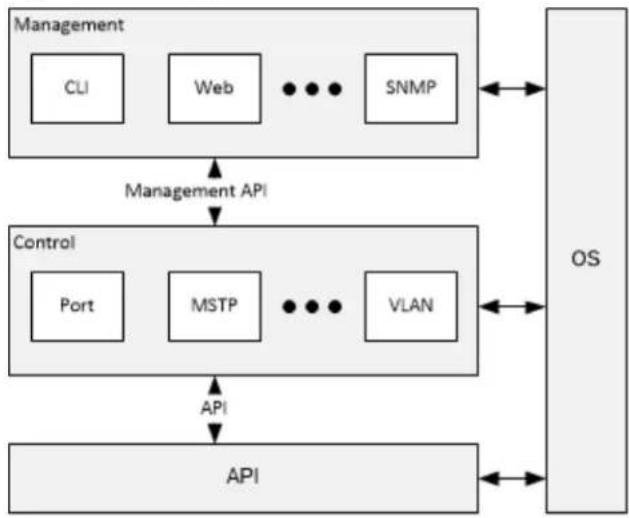
2.2 Soware Architecture
The CEServices soware provides support for standalone switches. It consists of the following components.
- Operang system (Linux) for access to the hardware.
• Applicaon programming interface (API) for a funcon library to control switches and PHYs. - Control modules, such as port control, MSTP, and Virtual LAN (VLAN)—to implement produce features and protocols. These modules may include threads and provide a management API configuration and monitoring.
- Management modules, such as CLI, web, JSON-RPC, and Simple Network Management Protocol (SNMP)—for interfaces to the system based on the management API of the control module
The following illustraon shows the architecture of the Microsemi managed applicaon soware and a few control and management modules.
Figure 1 • Applicaon Architecture
flowchart
graph TD
    A["Management"] --> B["CLI"]
    A --> C["Web"]
    A --> D["..."]
    A --> E["SNMP"]
    F["Control"] --> G["Port"]
    F --> H["MSTP"]
    F --> I["..."]
    F --> J["VLAN"]
    K["API"] --> L["OS"]
    style A fill:#f9f,stroke:#333
    style F fill:#ccf,stroke:#333
    style K fill:#cfc,stroke:#333
    style L fill:#fcc,stroke:#333
3 Supported Features
The following seconds describe the features of each module of the CEServices soware.
3.1 BSP and API
The following table lists the features supported by the API module.
Table 4 • BSP and API: Supported Features
| Feature | Serval-1VSC7416VSC7418 | Jaguar-2VSC7438VSC7464VSC7468 | Serval-TVSC7430VSC7435VSC7436VSC7437 |
| •••Internal CPU | |||
| •••API and applicaon split | |||
| •••MESA layer | |||
| •••MEBA layer |
3.2 Port Control
The following table lists the features supported by the port control module. For more inform Port Control on page 38.
Table 5 • Port Control: Supported Features
| Feature | Serval-1 | Jaguar-2 | Serval-T |
| VSC7416 | VSC7438 | VSC7430 | |
| VSC7418 | VSC7464 | VSC7435 | |
| VSC7468 | VSC7436 | ||
| VSC7437 | |||
| •••Port speed/duplex mode/flow coil | |||
| •••802.1Qbb per priority flow cont | |||
| •••Aquana 2.5G PHY Gen2 | |||
| •••Aquana 2.5G PHY Gen3 | |||
| •Aquana 5G PHY | Gen3 | ||
| ••Aquana 10G PHY Gen2 | |||
| •••Port frame size (jumbo frames) | |||
| •••Port state (administrave status) | |||
| •••Port status (link monitoring) | |||
| •••Port stascs (MIB counters) | |||
| Feature | Serval-1VSC7416VSC7418 | Jaguar-2VSC7438VSC7464VSC7468 | Serval-TVSC7430VSC7435VSC7436VSC7437 |
| •••Port VeriPHY (cable diagnoscs) | |||
| •••PoE/PoE+ with PD69208 support | |||
| col (LLDP) | •••PoE/PoE+ with Link Layer Discov w/o LLDP | ||
| •••PoE IEEE802.3bt | |||
| •••NPI port | |||
| •••PCIe | |||
| •••On-the-fly SFP detecon | |||
| •••DDMI | |||
| •••Unidireconal Link Detecon (UDLD) |
3.3 Quality of Service (QoS)
The following table lists the features supported by the QoS module. For more informaon, see Quality of Service (QoS) on page 40.
Table 6 • QoS: Supported Features
| Feature | Serval-1 | Jaguar-2 | Serval-T |
| VSC7416 | VSC7438 | VSC7430 | |
| VSC7418 | VSC7464 | VSC7435 | |
| VSC7468 | VSC7436 | ||
| VSC7437 | |||
| •••Traffic classes (8 acve priories) | |||
| •••Port default priority | |||
| •••User priority | |||
| •••Input priority mapping | |||
| •••QoS control list (QCL mode) | |||
| •••Global storm control for UC, M | |||
| •••Random early discard (RED) | |||
| •••Port policers | |||
| •••Service policing (including BW pr | |||
| •••Queue policers | |||
| •••Global/VCAP (ACL) policers | |||
| •••Port egress shaper | |||
| •••Queue egress shapers | |||
| •••DiServ (RFC2474) remarking | |||
| •••Tag remarking | |||
| •••Scheduler mode | |||
| •••H-QoS scheduling |
3.4 L2 Switching
The following table lists the features supported by the L2 switching module. For more inform L2 Switching on page 43.
Table 7 • L2 Switching: Supported Features
| Feature | Serval-1 | Jaguar-2 | Serval-T |
| VSC7416 | VSC7438 | VSC7430 | |
| VSC7418 | VSC7464 | VSC7435 | |
| VSC7468 | VSC7436 | ||
| VSC7437 | |||
| IEEE 802.1D Bridge | |||
| •••Auto MAC address learni | |||
| •••MAC addresses—stac | |||
| IEEE 802.1Q | |||
| •••Virtual LAN | |||
| •••Bidireconal VLAN translaor | |||
| •••Unidireconal VLAN translac | |||
| •••Private VLAN—stac | |||
| •••Port isolaon—stac | |||
| •••MAC-based VLAN | |||
| •••Protocol-based VLAN | |||
| •••IP subnet-based VLAN | |||
| Feature | Serval-1VSC7416VSC7418 | Jaguar-2VSC7438VSC7464VSC7468 | Serval-TVSC7430VSC7435VSC7436VSC7437 |
| •••VLAN trunking | |||
| •••iPVLAN trunking | |||
| •••GARP VLAN Registraon PI | |||
| •••Mulple Registraon Protoco | |||
| •••Mulple VLAN Registraon | |||
| •••IEEE 802.1ad provider bri | |||
| •••EVC classificaon of L4 fl | |||
| ••7-tuple EVC rules | |||
| ••Mulple COS per EVC | |||
| ••MEP CLM resource improv | |||
| ••EVC service class configura | |||
| ••Decouple use of VSI and | |||
| ••Per port parameter (UNI | |||
| •••E-ACCESS (EPL, EVPL) | |||
| •••E-LINE (EPL, EVPL) | |||
| •••E-LAN (EP-LAN, EVP-LAN) | |||
| •••E-TREE (EP-TREE, EVP-TREE | |||
| •EoMPLS LER (PWE) | |||
| LSR | • | ||
| •LSP/PW AIS/LCK | |||
| •MPLS-TP: E-LINE (EPL, EVPL) | |||
| •MPLS-TP: E-LAN (H-VPLS, EP-LAN, EVP-LAN) | |||
| •MPLS-TP: LSR E-LINE (EPL, EVPL) | |||
| •••L2CP tunneling | |||
| ••L2CP profiles (ingress/egress | |||
| •••Mulple Spanning Tree Pro | |||
| •••Rapid Spanning Tree Prot | |||
| ●●●Loop guard | |||
| ●●●Link aggregaon stac | |||
| ●●●Link aggregaon LACP | |||
| ●●●BPDU guard and restricte | |||
| ●●●AGGR/LACP user interface | |||
| ●●●UNI LAG (LACP) 1:1 acv | |||
| ●●●LACP reverve/non-reverve | |||
| ●●●LACP loop free operaon | |||
| ●●●Error disable recovery | |||
| ●●●IGMPv2 snooping | |||
| ●●●MLDv1 snooping | |||
| ●●●IGMP filtering profile | |||
| ●●●IPMC throling, filtering, le | |||
| ●●●Mulcast VLAN Registraon | |||
| ●●●MVR profile | |||
| ●●●Voice VLAN | |||
| ●●●DHCP snooping | |||
| ●●●ARP inspecon | |||
| ●●●Port mirroring | |||
| ●●●Flow mirroring | |||
| ●●●Rmirror | |||
3.5 Protecon
The following table lists the features supported by the protecon module. For more informaon, Protecon on page 49.
Table 8 • Protecon: Supported Features
| Feature | Serval-1 | Jaguar-2 | Serval-T |
| VSC7416 | VSC7438 | VSC7430 | |
| VSC7418 | VSC7464 | VSC7435 | |
| VSC7468 | VSC7436 | ||
| VSC7437 | |||
| •••1:1 port protecon—G.8031 | |||
| •••Port protecon with services | |||
| •MPLS EVC 1:1 E-LINE protecon | |||
| •MPLS-TP 1:1 LSP protecon | |||
| •MPLS-TP fast re-route protecon | |||
| •••G.8032 ring protecon | |||
| •••G.8032 ring protecon v.2 | |||
3.6 L3 Switching
The following table lists the features supported by the L3 switching module. For more inform L3 Switching on page 51.
Table 9 • L3 Switching: Supported Features
| Feature | Serval-1VSC7416VSC7418 | Jaguar-2VSC7438VSC7464VSC7468 | Serval-TVSC7430VSC7435VSC7436VSC7437 | relay |
| •••DHCP opon 82 | ||||
| •••UPNP | ||||
| Linux Kernel integraon | •Soware-based IPv4 | L3 stac roung | with | |
| Linux Kernel integraon | ••Hardware-based IPv4 L3 stac rou support for HW | |||
| stac roung | ••RFC2992 (ECMP) | |||
| •Soware-based IPv6 | L3 stac roung | |||
| ••Hardware-based IPv6 L3 stac rou | ||||
| sum, and so on) | •••RFC-1812 L3 checking (version, |
3.7 Security
The following table lists the features supported by the security module. For more informaon, Security on page 52.
Table 10 • Security: Supported Features
| Feature | Serval-1VSC7416VSC7418 | Jaguar-2VSC7438VSC7464VSC7468 | Serval-TVSC7430VSC7435VSC7436VSC7437 | |
| •••Port-based 802.1X | ||||
| •••Single 802.1X | ||||
| •••Mulple 802.1X | ||||
| •••MAC-based authencaon | ||||
| •••VLAN assignment | ||||
| •••QoS assignment | ||||
| •••Guest VLAN | ||||
| caon and authorizaon | •••Remote Authencaon Dial | |||
| •••RADIUS accoung | ||||
| •••MAC address limit | ||||
| •••Persistent MAC learning | ||||
| •••IP MAC binding | ||||
| •••IP/MAC binding dynamic | ||||
| •••TACACS+ authencaon and command author | ||||
| •••TACACS+ accoung | ||||
| •••Web and CLI authencaon | ||||
| •••Authorizaon (15 user level filtering/policing/ | ||||
| •••ACLs for guard | ||||
| •••IP source | ||||
| •••Secure FTP client |
3.8 Timing and Synchronizaon
The following table lists the features supported by the ming and synchronizaon module. For informaon, see Timing and Synchronizaon on page 57.
Table 11 • Timing and Synchronizaon: Supported Features
| Feature | Serval-1VSC7416VSC7418 | Jaguar-2VSC7438VSC7464VSC7468 | Serval-TVSC7430VSC7435VSC7436VSC7437 |
| •••SyncE with SSM | |||
| •••SyncE nominaon for 2 i | |||
| •1 ns accuracy ming suppo | |||
| •••Microsemi one-step TC P | |||
| •••IEEE 1588v2 PTP with t | |||
| •••IEEE 1588v2 PTP with o | |||
| •••Peer-to-peer transparent c | |||
| •••End-to-end transparent clo | |||
| •••End-to-end transparent clo | |||
| •••Boundary clock | |||
| •••Redundant masters and r | |||
| •••PTP over IPv4 | |||
| •••Unicast/mulcast | |||
| or latency feedback from modems | •••TC internal master/slave | ||
| provides feedback on modulaon or latency-only ZLS30384and ZLS30380 | •••TC internal master/slave | ||
| •••Combined SyncE and 158 | |||
| •••MSCC ming BU servo al | |||
| •••MSCC ming BU DPLL AF | |||
| •Serval-TE Intermediate Servo | |||
| •••G.8265.1 BMCA (MSCC ZI | |||
| •••ITU G.8263 filtering (MSC | |||
| •••PTP profile (MSCC ZLS303 | |||
| •••Clock Quality (MSCC ZLS3 | |||
| PTP slave (MSCC ZLS30384 and MSCC ZLS30380 only) | •••G.781 compliant clock se | ||
| •••G.8275.1 BMCA-only ZLS3 | |||
| •••G.8275 compliant filter-on | |||
| •••PTP me interface | |||
| •••NTPv4 client | |||
| •••IEEE802.1AS-2011/IEEE802.1AS |
3.9 Carrier Ethernet (OAM and Tesng)
The following table lists the features supported by the Carrier Ethernet (OAM and Tesng) more informaon, see Carrier Ethernet (OAM and Tesng) on page 60.
Table 12 • Carrier Ethernet (OAM and Tesng): Supported Features
| Feature | Serval-1VSC7416VSC7418 | Jaguar-2VSC7438VSC7464VSC7468 | Serval-TVSC7430VSC7435VSC7436VSC7437 |
| ●●●802.3ah: Variable, request, Discovery process | |||
| loopback | ●●●802.3ah: | ||
| ●●●802.3ah: Dying gasp | |||
| ●●●802.3ah: Dying gasp enha | |||
| ●●●802.3ah: Dying gasp SNM | |||
| ●●●Flow OAM: Ingress/egress | |||
| ETH-RDI) | ●●●FM: Connuity check and | ||
| ●●●FM: Loopback (ETH-LB) | |||
| ●●●FM: Link trace (ETH-LT) | |||
| ●●●FM: CFM dynamic TLV | |||
| ●●●FM: Alarm indicaon signa | |||
| ●●●FM: Locked signal (ETH-L) | |||
| ●●●FM: Test signal (ETH-Test | |||
| ●●●FM: Automac protecon s | |||
| LM) | ●●●PM: Dual ended frame | ||
| (ETH-LM) | ●●●PM: Single ended frame | ||
| ●●●PM: Frame delay and d | |||
| ●PM: Synthec loss measurement (SLM/SLR)—soware-based | |||
| ●●PM: Synthec loss measure | |||
| ●●●PM: Organizaon-specific TL | |||
| ●●●EPS/ERPS using ETH-CCM | |||
| ●●●OAM inject engine supp | |||
| ●●●OAM inject engine supp | |||
| ●●●Nested MEPs | |||
| ●●●Link state tracking | |||
| ●●●FM: Link trace PDU (LTI | |||
| ●●●FM: Loopback PDU (LBM) | |||
| ●●Subscriber MIP | |||
| ●Mulpoint OAM—soware-based | |||
| ●●Mulpoint OAM—hardware-ba | |||
| ●●●Microsemi OAM Y.1731 F | |||
| ●●●Syslog for congeson fault | |||
| ●●●RFC2544 | |||
| ●●●RFC2544 LBM/LMR suppor | |||
| ●●●Advanced service acvaon | |||
| ●●●Single-ended measurement | |||
| •••SAM Y.1564 reflector sup | |||
| •ETH OAM for LSP and service protecon | |||
| •Y.1731 ETH OAM over LSP/PW | |||
| •PW OAM (RFC 5085 VCCV, RFC 5885 BFD using P) | |||
| •MPLS-TP OAM (using GAL and ACH - RFC 5586 an | |||
| •G.8113.2 IETF OAM protocol suite | |||
| •••SMAC/DMAC swap | |||
| •••Facility (NNI) TT data re | |||
| •••MEF 46 latching loopback | |||
| domain | •••Facility (NNI) TT data ar | ||
| main | ••Terminal (UNI) TT OAM i | ||
| ••Terminal (UNI) TT OAM i | |||
| link layer Ethernet | •Pop/Push operaon including SWAP of MPLS-label stack | ||
| •••OAM HW engine | |||
| •••MEF 35 phase 1 (perfor | |||
| •••MEF 35 phase 2 (perfor | |||
| •••MEF 35 phase 3 (perfor | |||
3.10 Robustness and Power Savings
The following table lists the features supported by the robustness and power savings module. informaon, see Robustness and Power Savings on page 69.
Table 13 • Robustness and Power Savings: Supported Features
| Feature | Serval-1VSC7416VSC7418 | Jaguar-2VSC7438VSC7464VSC7468 | Serval-TVSC7430VSC7435VSC7436VSC7437 |
| ●●●Cold start | |||
| ●●●Cool start | |||
| ●●●AcPHY | |||
| ●●●PerfectReach | |||
| ●●●EEE power management | |||
| ●●LED power | management | ||
| ●●●Thermal protecon | |||
| ●●●Adapve fan control |
3.11 Customizaon Framework
The following table lists the features supported by the customizaon framework module.
Table 14 • Customizaon Framework: Supported Features
| Feature | Serval-1VSC7416VSC7418 | Jaguar-2VSC7438VSC7464VSC7468 | Serval-TVSC7430VSC7435VSC7436VSC7437 |
| •••Separate BSP and applica | |||
| •••Allow customers to appe | |||
| •••IPC JSON-RPC socket (wit | |||
| •••Overwrite default startup | |||
| •••Boot and initializaon of t | |||
| •••Configuraon to disable ce | |||
| •••Microsemi Ethernet board |
3.12 Management
The following table lists the features supported by the management module. For more information Management on page 71.
Table 15 • Management: Supported Features
| Feature | Serval-1VSC7416VSC7418 | Jaguar-2VSC7438VSC7464VSC7468 | Serval-TVSC7430VSC7435VSC7436VSC7437 |
| •••JSON-RPC | |||
| •••JSON-RPC noficaons | |||
| •••Dual CPU (applicaon varia | |||
| •••Double VLAN tag manage | |||
| •••RFC 2131 DHCP client | |||
| •••DHCP Server support for | |||
| •••DHCP per port | |||
| •••RFC 3315 DHCPv6 client | |||
| •••RFC 3315 DHCPv6 relay |
| Feature | Serval-1VSC7416VSC7418 | Jaguar-2VSC7438VSC7464VSC7468 | Serval-TVSC7430VSC7435VSC7436VSC7437 | |
| servers | ●●●RFC 7610 | DHCPv6-shield | ||
| ●●●RFC 2131 | DHCP server | |||
| ●●●RFC 1035 | DNS client, re | |||
| ●●●IPv4/IPv6 | Ping | |||
| ●●●IPv4/IPv6 | Traceroute | |||
| ●●●HTTP server | ||||
| ●●●CLI—console port | ||||
| ●●●CLI—Telnet | ||||
| ●●●Industrial | standard CLI | |||
| ●●●Industrial | standard configu | |||
| ●●●Industrial | standard CLI de | |||
| ●●●Port descripon CLI | ||||
| ●●●UI EVC naming | ||||
| ●●●Management access filterir | ||||
| ●●●HTTPS | ||||
| ●●●SSHv2 | ||||
| ●●●IPv6 management | ||||
| ●●●IPv6 ready logo PHASE2 | ||||
| ●●●RFC4884 (ICMPv6) | ||||
| ●●●System syslog | ||||
| ●●●Soware upload through v | ||||
| ●●●SNMP v1/v2c/v3 agent (1 | ||||
| ●●●RMON (group 1, 2, 3, | ||||
| ●●●RMON alarm and event | ||||
| ●●●Alarm module | ||||
| ●●●IEEE 802.1AB-2005 link la |
| Feature | Serval-1VSC7416VSC7418 | Jaguar-2VSC7438VSC7464VSC7468 | Serval-TVSC7430VSC7435VSC7436VSC7437 |
| •••TIA 1057 LLDP—MED | |||
| •••Industry standard discover | |||
| •••sFlow | |||
| •••FTP client | |||
| •••Configuraon download/upload | |||
| •••Loop detecon restore to | |||
| •••Symbolic register access | |||
| •••Daylight saving | |||
| •SD/MMC card slot support | |||
Note:
1. No SNMPv1 trap support.
3.13 SNMP MIBs
The following table lists the features supported by the SNMP MIBs module. For more inform SNMPMIBs on page 81.
Table 16 • SNMP MIBs: Supported Features
| Feature | Serval-1VSC7416VSC7418 | Jaguar-2VSC7438VSC7464VSC7468 | Serval-TVSC7430VSC7435VSC7436VSC7437 | |
| ●●●RFC 2674 | VLAN MIB | |||
| ●●●IEEE 802.1Q bridge MIB | ||||
| ●●●RFC 2819 | RMON (group | |||
| ●●●RFC 1213 | MIB II | |||
| ●●●RFC 1215 | TRAPS MIB | |||
| ●●●RFC 4188 | bridge MIB | |||
| ●●●RFC 4292 | IP forwarding | |||
| col (IP) | ●●●RFC 4293 | management irmulcast groupRADIUS authenRADIUS accounEthernet-like Minterface group802.3 MAU menty MIB versLink OAM MISNMP manageruser-based secview-based accSMON—PortCop | ||
| ●●●RFC 5519 | ||||
| ●●●RFC 4668 | ||||
| ●●●RFC 4670 | ||||
| ●●●RFC 3635 | ||||
| ●●●RFC 2863 | ||||
| ●●●RFC 3636 | ||||
| ●●●RFC 4133 | ||||
| ●●●RFC 4878 | ||||
| ●●●RFC 3411 | ||||
| ●●●RFC 3414 | ||||
| ●●●RFC 3415 | ||||
| ●●●RFC 2613 | ||||
| ●●●IEEE 802.1 | MSTP MIB | |||
| STD) | ●●●IEEE 802.1AB LLDP-MIB (I | |||
| ●●●IEEE 802.3ad (LACP MIB | ||||
| ●●●IEEE 802.1X (PAE MIB in | ||||
| ●●●TIA 1057 | LLDP-MED (MIB | |||
| ●●●RFC 3621 | LLDP-MED pow | |||
| ●●●Private MIB framework | ||||
4 Features and Plaorm Capacity
The following table lists the features and plaorm capacity supported by the CE Services sowa capacity menoned can be either soware or hardware constrained.
Table 17 • Features and Plaorm Capacity
| Feature | Serval-1VSC7416VSC7418 | Jaguar-2VSC7438VSC7464VSC7468 | Serval-TVSC7430VSC7435VSC7436VSC7437 |
| Resilience and Availability | |||
| stances | 888IEEE 802.1s MSTP in- | ||
| LAGs | 3 LAGs in VSC7416 | 13 LAGs in VSC7464 | 3 LAGs in VSC74307 LAGs in VSC743855 LAGs in VSC743626 LAGs in VSC7468 |
| Traffic Control | |||
| 409540954095Port-based VLAN | |||
| 111Guest-VLAN | |||
| Private VLAN | 11 in VSC7414/187 in VSC7416 | 14 in VSC743852 in VSC746826 in VSC7464 | 6 in VSC743010 in VSC7436 |
| 111Voice VLAN | |||
| MAC table size | 8K 8K | 32K | 8K in VSC743016K in VSC7436 |
| Storm control | 1, 2, 4, 8, 16, 32, 56, 512, 1000, 2000, 8000, 16000, 32000, 64000 (known/learned), 128000, 256000, 512000 broadcast, and Un- or 1024000 kpps (globaknown (flooded unicast seng for Unicast, Mul- cast, and Broadcast) | 6200 128ps-210000004000 [per port for | 100 kbps-1000000 kbps [per port funi-Unicast (known/learned), Broadcast, and Unknown (flood- ed unicast and mulcast)] |
| Jumbo frames supported | Up to 10240 | Up to 10240 | Up to 10240 |
| Security | |||
| Port security aging | 10 to 10000000s | 10 to 10000000s | 10 to 10000000s |
| 102410241024MAC address limit | |||
| Stac MAC entries supported | 64 | 64 | 64 |
| servers | 555RADIUS authencaon | ||
| servers | 555TACACS+ authencaon | ||
| servers | 555RADIUS accounng | ||
| 444Telnet/SSH v2 | |||
| 1K per system1K per systemMax ARP insj to 512 per s | |||
| Up to 512 per systemUp | |||
| tering | 512512512Policy-based security fil- | ||
| Password length 32 | 3232 | ||
| Authorization user level | 1515 | ||
| 512512512ACE | |||
| users | Number of logged in20 | 2020 | |
| 333Authentication methods | |||
| Telnet/SSH | 4/4 | 4/4 | 4/4 |
| QoS | |||
| 802.1p | |||
| 888Priority queues per port | |||
| 256512256QCE | |||
| Rate liming, port based kbps–3300000 kbps (ingress/ egress) | 100 kbps–1320000000 kbps–13200000 kbps kbps | ||
| Policy-based bandwidth control granularity | 1 pps–131071 pps | 1 pps–131071 pps | 1 pps–131071 pps |
| Queue policers | Per port on queues 0–7 | Per port on queues 0–7 | Per port on queues 0–7 |
| Layer 2 Mulcast | |||
| (shared across IGMP MLD) | Mulcast MAC groups 1K and | 1K1K | |
| MVR groups (shared across IGMP and MLD) | |||
| Manageability | |||
| 111Syslog servers supported | |||
| 100100100Max log messages(1) | |||
| 444Max trap desnaons | |||
| Maintenance | |||
| SupportedSupportedSupportedHTTP/HTTPS supp | |||
| tering | 161616Management access fil- | ||
| 111DHCP relay | |||
| uraon | 646464DHCP server pool config- | ||
| 111DNS proxy, client | |||
| 555NTPv4 servers | |||
| EVCs | |||
| Max EVC rules | 256/1024 | 1261022 | |
| Max ECE rules | 256/1024 | 3783066 | |
| Max BW profiles | 256/1022 | 4096 | 4096 |
| Roung | |||
| 1281288VLAN roung interfaces | |||
| 3212832Stac routes | |||
| Max HW round table entries | No HW round table | 4000 | 1000 |
| Y.1564 | |||
| 161616Traffic profiles | |||
| 101010Test reports | |||
Note:
- The maximum number of buered logs is based on log message length and is limited stored size (10K).
5 System Requirements
The following tables lists the port system requirements supported by the CEServices soware.
Table 18 • Port System Requirements
| Feature | Serval-1VSC7416VSC7418 | Jaguar-2VSC7438VSC7464VSC7468 | Serval-TVSC7430VSC7435VSC7436VSC7437 |
| 111LEDs per port | |||
| SFP auto-deteconSFP auto-detecon: | |||
| SupportedSupportedSupportedSpeed | |||
| Duplex capability per 10/100M | Half/full | Half/full | Half/full |
| SupportedSupportedSupportedAuto I | |||
| Port packet forwarding rate | 1488000 pps (100 Mbps with 64 bytes) 14880000 pps (100 Mbps) 14880000 pps (100 Mbps) 14880000 pps (100 Mbps) 14880000 pps (100 Mbps) 14880000 pps (100 Mbps) 14880000 pps (100 Mbps) 14880000 pps (1 10 Mbps) 14880000 pps (100 Mbps) 14880000 pps (100 Mbps) 14880000 pps (100 Mbps) 14880000 pps (100 Mbps) 14880000 pps (100 Mbps) 14880000 pps(10 Mbps) 14880000 pps (100 Mbps) 14880000 pps (100 Mbps) 14880000 pps (100 Mbps) 14880000 pps (100 Mbps) 14880000 pps (100 Mbps) 14880000 pPS (10 Mbps) 14880000 pPS (100 Mbps) 14880000 pPS (100 Mbps) 14880000 pPS (100 Mbps) 14880000 pPS (100 Mbps) 14880000 pPS (100 Mbps) 14880000 pPS (100 Mbps) 14880000 pPS(10 Mbps) 14880000 pPS (100 Mbps) 14880000 pPS (100 Mbps) 14880000 pPS (100 Mbps) 14880000 pPS (100 Mbps) 14880000 pPS (100 Mbps) 14880000 pPPS (10 Mbps) 14880000 pPS (100 Mbps) 14880000 pPS (100 Mbps) 14880000 pPS (100 Mbps) 14880000 pPS (100 Mbps) 14880000 pPS (100 Mbps) 1488000 | ||
| SupportedSupportedSupportedRJ45 c | |||
| SupportedSupportedSupportedFiber : | |||
The following tables lists the hardware system requirements supported by the CEServices sowar
Table 19 • Hardware System Requirements
| Requirement | Support |
| Power LED | Supported by hardware |
| System LED | Supported by hardware |
| Alarm LED | Supported by hardware |
| Switch fabric capacity | Supported by hardware |
| Forwarding architecture | Supported by hardware |
| MAC address entries | Supported by hardware |
| MAC address aging | Supported by hardware |
| MAC buer memory type and size | Supported by hardware |
| CPU flash size | Supported by hardwareSupportRequirement |
| Supported by hardwareCPU memory type and | |
| Supported by hardwareSystem DDR SDRAM | |
| Supported by hardwareReset buon | |
| Supported by hardwareRoung capability | |
| Supported by hardwareEMC/safety requirement | |
| Supported by hardwarePerformance requirement |
size
6 Port and System Capabilities
The following seconds describe the port and system capabilities supported by the CEServices sow
6.1 Port Capability
The ports are equipped with the following capabilities.
- All copper ports can be configured as full-duplex or half-duplex.
• Copper ports operang at 10/100 Mbps support auto-sensing and auto-negoaon.
• Full-duplex, auto-sensing, and auto-negoaon are supported on 1000 Mbps ports.
• Full-duplex flow control is supported according to the IEEE 802.3x standard.
• Half-duplex flow control is supported using collision-based backpressure.
• LEDs for all the ports are driven by the SGPIO and Shi registers. - Dierent port-based configuraons are supported on all available ports. For more informaon, Supported Features on page 14.
6.2 System Capability
The 6- to 52-port turnkey switch platform model switches can be supported using the CEServic with wire speed layer 2 Gigabit/Fast Ethernet switches, with an opon to additionally support t capability with partner vendors.
The turnkey switch soware runs on Linux. The following system-wide operaons are supported.
• Store-and-forward forwarding architecture.
- Configurable MAC address aging support (300 seconds default meout value).
- Port packet-forwarding rates of 1488095 pps (1000 Mbps), 148810 pps (100 Mbps), and 1 (10 Mbps).
• 128-MB system DDR SDRAM is recommended for a typical 24- to 48-port switch.
• 16-MB flash size is recommended for a typical 24- to 48-port switch.
7 Firmware Upgrade
The CEServices firmware, which controls the switch, can be updated using one of the following
• Web, using the HTTP protocol
• CLI, using the TFTP client on the switch
The soware image selecon informaon includes the following:
• Image—the file name of the firmware image
• Version—the version of the firmware image
- Date—the date when the firmware was produced
Aer the soware image is uploaded from the web interface, a web page announces that the update is initiated. Aer about a minute, the firmware is updated and the switch restarts.
While the firmware is being updated, web access appears to be defunct. The front LED flas with a frequency of 10 Hz while the firmware update is in progress.
Note:
Do not restart or power o the device at this me or the switch may fail to funcon.
8 Port Control
The following seconds describe the port control features supported by the CEServices soware.
8.1 NPI Port
The CEServices soware supports the NPI port to manage the switch core. Any front port can be configured as an NPI port through which frames can be injected from and extracted to an
8.2 PCIe
The PCIe interface allows a back-to-back conncon with an external CPU. The external CPU h read/write access to device registers and can burst frame-data in (injection) and out (extraction memory-mapped injecon/extracon registers.
8.3 Dual CPU (Applicaon Variant with JSON)
The CEServices soware supports a dual system where both the internal and external CPU are at the same me.
8.4 SFP Detecon
The CEServices soware detects SFP at run me.
8.5 VeriPHY Support
The CEServices soware provides VeriPHY support to run cable diagnoses to find cable shorts/op and to determine cable length.
8.6 PoE/PoE+ Support
The CEServices soware provides PoE/PoE+ support to comply with the IEEE 802.3at and IEEE standards of enabling the supply of up to 30 W per port and up to the total power bu
8.7 POE/POE+ with LLDP
The CEServices soware allows automac power configuraon if the link partner supports PoE. With LLDP is enabled, the informaon about the power usage of the PD is available, and then the comply with or ignore this informaon.
8.8 Unidireconal Link Detecon (UDLD)
UDLD is used to determine the physical status of the link and to detect a unidireconal link. A UDLD packet is sent to the port it links to for each device and for each port. The p identity informaon of the sender (device and port) and expected receiver identity informaon (dev and port). Each port checks that the UDLD packets it receives contain the idenfiers of its and port.
The UDLD implementaon conforms to the RFC5171 standard.
Note:
RFC5171 is unclear about timers as well as messaging sequences. It is assumed that prob will initially be exchanged every second, and once link status is detected, probe messages exchanged depending on message me interval (by default 7 seconds).
Time Interval Type Length Value (TLV), message interval TLV, and sequence interval TLV are supported due to insufficient information in this RFC.
Detecon starts once the UDLD enabled port gets new device ID and port ID pair. If a po as unidireconal or loopback link, the port is shut down if mode is Aggressive. In Normal n will not be shut down.
Port is reopened once UDLD is disabled/enabled on that port.
9 Quality of Service (QoS)
The following seconds describe the rich QoS features supported by the CEServices soware.
9.1 Port Policers
The QoS ingress port policers are configurable per port and are disabled by default. The so disable/enable flow control on the port policer. Flow control is disabled by default. If flow is enabled and the port is in flow control mode, then pause frames are sent instead of disc
9.2 Scheduling and Shaping
Each egress port implements a scheduler that controls eight queues, one queue (priority) per The scheduler mode can be set to strict priority or weighted (modified-DWRR). Strict priority by default. It is possible to specify the weight for each of the queues (0–5).
Each egress port also implements a port shaper and a shaper per queue. The soware allow disabling/enabling the port and queue shaper as part of egress shaping. The port shaper and shaper are disabled by default.
It is possible to specify the maximum bit rate in kbps or mbps. The use of excess bandwidth is configurable and is disabled by default.
The soware also has the QoS leaky bucket egress shapers support per queue (0-7) as well
9.3 QCL Configuraon
QoS classificaon based on basic classificaon can be overruled by an intelligent classifier called Control List (QCL).
The QCL consists of QCE entries where each entry is configured with keys and acons. The which part of the frames must be matched and the acons specify the applied classificaon p
When a frame is received on a port, the list of QCEs is searched for a match. If the f configured keys, the acons are applied and the search is terminated.
The QCL configuraon is a table of QCEs containing QoS control entries that classify to a sp class on specific traffic objects. A QoS class can be associated with a parcular QCE ID.
9.4 Weighted Random Early Detecon (WRED)
While the random early detecon (RED) sengs are configurable for queues 0–5, WRED is config to either disable/enable, and is disabled by default.
The minimum and maximum percentage of the queue fill level or drop probability can be c before WRED starts discarding frames.
By specifying a dierent RED configuraon for the queues (QoS classes), it is possible to obtain WRED operaon between queues.
9.5 Tag Remarking
Tag remarking determines how an egress frame is edited before transmission. This includes the of PCP and DEI values in tagged frames.
When adding a VLAN tag, the soware allows specifying a mode where the PCP and DEI va from Classified, Mapped, or Default. Classified is the default.
The QoS class DEI, DP Level to PCP, can also be mapped for QoS egress tag remarking p the classificaon is set to Mapped.
9.6 Ingress Port Classificaon
Classificaon is the first step for implementing QoS. There is a one-to-one mapping between QoS queue, and priority. The QoS class is represented by numbers; higher numbers correspond to priority.
The features supported are as follows:
• Port default priority (QoS class)
• Port default priority (DP level)
- Port default PCP
- Port default DEI
• DSCP mapping to QoS class and DP level
• DSCP classificaon (DiServ)
• Advanced QoS classificaon
9.7 Queue Policers
The queue policers are configurable per queue and are disabled by default.
9.8 HQoS
Hierarchical quality of service scheduling (HQoS) is a mechanism for providing egress QoS cont Ethernet services (EVCs). Hardware supports HQoS with three layers of scheduling and four lay shaping. HQoS is defined to provide guaranteed scheduling bandwidth for each EVC and QoS an EVC, both towards the network to network Interface (NNI) and the user network interface
The port scheduler can be configured in three dierent modes for HQoS.
- Normal
- Basic
- Hierarchical
It is possible to disable/enable and configure the minimum bandwidth for each EVC on a po Hierarchical mode. Default HQoS scheduling hierarchy is as follows.
- Scheduling among classes of service within EVC
- Scheduling among EVCs on the same path/tunnel
- Scheduling among paths/tunnels on the same port
9.9 DiServ (RFC2474) Remarking
The CEServices soware allows disabling/enabling port DSCP remarking, which is disabled by defa Port DSCP remarking is possible for both IPv4 and IPv6.
In addition to the ingress DSCP remarking done by the analyzer, the rewriter supports egress remarking of IP (IPv4 and IPv6) frames where the actual change is made to the DSCP field
The remarking can be configured as enable/disable per egress port. It is also possible to en DSCP remapping on the egress port and to use the translated DSCP value for DSCP remarki
DSCP remapping is disabled by default. If DSCP remarking is enabled, the new DSCP value in frame is either from the analyzer (basic classificaon or advanced classificaon based on TCAM), from the DSCP remapped on egress. The following configuraon opons are available if DSCP re is enabled.
- Get the DSCP value from the analyzer (ingress classificaon) and always remap based on remap table. This is done independently of the value of the drop precedence level.
• Get DSCP value from the analyzer and remap based on drop precedence level and rema
DSCP remarking is not possible for frames where Precision Time Protocol (PTP) me stamps are generated. It is automatically disabled in such cases. It is possible to configure per DSCP (0–6) for each QoS class and set the DPL. The per DSCP value parameters are configurable for [The soware allows mapping QoS class and DPL to DSCP value on the CEServices soware.
9.10 Global Storm Control
Global Storm Control on the CEServices soware is done per system globally on SparX-III and based switches. Global storm rate control configuraon for unicast frames, broadcast frames, and mulcast frames is supported and can be configured in pps on SparX-III switches.
On the E-StaX-III switch models, storm control is configured per port. Storm rate control conl for unicast frames, broadcast frames, and a storm rate control configuraon for unknown (flooc frames can be configured in kbps, Mbps, fps, and kfps on the E-StaX-III-based switches.
Storm control is disabled by default.
10 L2 Switching
The following seconds describe the L2 switching features supported by the CEServices soware.
10.1 Virtual LAN
The CEServices software supports the IEEE 802.1Q standard virtual LAN (VLAN). The default con is as follows.
• All ports are VLAN aware.
• All ports are members of VLAN 1.
• The switch management interface is on VLAN 1.
• All ports have a Port VLAN ID (PVID) of 1.
- A port can be configured to one of the following three modes.
- Access
- Trunk
- Hybrid
- By default, all ports are in Access mode and are normally used to connect to end state ports have the following characteristics.
• Member of exactly one VLAN, the Port VLAN (Access VLAN), which by default is 1.
- Accepts untagged and C-tagged frames.
• Discards all frames that are not classified to the Access VLAN.
- On egress all frames classified to the Access VLAN are transmitted untagged. Others (dynamically added VLANs) are transmied tagged.
• The PVID is set to 1 by default.
- Ingress filtering is always enabled.
Trunk ports can carry traffic on mulple VLANs simultaneously, and are normally used to conn other switches. Trunk ports have the following characteristics.
- By default, a trunk port is a member of all VLANs (1–4095). This may be limited by the use of allowed VLANs.
- If frames are classified to a VLAN that the port is not a member of, they are discard
- By default, all frames classified to the Port VLAN (also known as Nave VLAN) get tagge Frames classified to the Port VLAN do not get C-tagged on egress.
- Egress tagging can be changed to tag all frames, in which case only tagged frames are ingress.
Hybrid ports resemble trunk ports in many ways, but provide the following additional port cor features.
- Can be configured to be VLAN tag unaware, C-tag aware, S-tag aware, or S-custom-tag a
- Ingress filtering can be controlled.
- Ingress acceptance of frames and configuraon of egress tagging can be configured independ
10.1.1 Voice VLAN
Voice VLAN is configured specially for voice traffic. Adding the ports with voice devices aache to perform QoS-related configuraon for voice data ensures the transmission priority of voice trans and voice quality. Individual opons allow the port to parcipate in a Voice VLAN using the feature. A configurable port discovery protocol will also be available to detect voice devices a to port using the Port Discovery Protocol. This discovery can be done either based on an Unique Idenfier (OUI) or Link Layer Discovery Protocol (LLDP) or both.
10.1.2 Private VLAN, Port Isolaon
In a private VLAN, communicaon between isolated ports in that private VLAN is not permied.
Private VLANs are based on the source port mask, and there are no connexons to VLANs. that VLAN IDs and private VLAN IDs can be identical.
10.1.3 MAC-Based, Protocol-Based, and IP Subnet-Based VLAN
A MAC-based VLAN enables mapping a specific MAC address to a specific VLAN.
A protocol-based VLAN enables mapping to a VLAN whose frame type may be one of the
- Ethernet—valid values for etype ranges from 0x0600-0x.
- SNAP—valid value in this case also is comprised of two sub-values.
- Organizaonally unique Idenfier (OUI).
- Protocol ID (PID)—if the OUI is hexadecimal 000000, the PID is the Ethernet type (Ether) value for the protocol running on top of SNAP. If the OUI is an OUI for a particular the PID is a value assigned by that organizaon to the protocol running on top of SNA
- LLC—valid value in this case is comprised of two sub-values:
• DSAP—1-byte long string (0x00-0x)
• SSAP—1-byte long string (0x00-0x)
The precedence of these VLANs is that the MAC-based VLAN is preferred over the protocol-b and protocol-based VLAN is preferred over port-based VLAN.
10.1.4 Auto MAC Address Learning/Aging
Learning is done automatically as soon as a frame with unknown SMAC is received. Dynamic removed from the MAC table aer a configured aging me (in seconds), if frames with learned address are not received within aging period.
10.1.5 MAC Addresses-Stac
Stacally-added MAC entries are not subjected to aging.
10.2 Industrial Private VLANs
This feature is widely known as private VLANs (PVLAN). VLANs limit broadcasts to specified us splits the broadcast domain into mulple isolated broadcast sub-domains and puts secondary VLA inside a primary VLAN.
PVLANs restrict traffic flows through their member switch ports (private ports) so that these communicate only with a specified uplink trunk port or with specified ports within the same uplink trunk port is usually connected to a router, firewall, server, or provider network. Each typically contains many private ports that communicate only with a single uplink, thereby prev the ports from communicating with each other.
The following terms are used to describe the Private VLAN feature.
- PVLAN domain—a VLAN domain paroned into a number of sub-domains. Inside the domain number of primary and secondary VLANs are used. Only the primary VLANs are known as PVLAN domain.
- Primary VLAN—a VLAN used inside and outside a PVLAN domain. A primary VLAN carries from promiscuous ports to isolated ports, and from community ports to other promiscuous
• Secondary VLAN—a VLAN used inside a PVLAN domain only.
• Isolated VLAN—a secondary VLAN that carries traffic from isolated ports to promiscuous po - Community VLAN—a secondary VLAN that carries traffic from community ports to promiscuo ports and other community ports.
- Isolated port—a port that receives untagged frames and classifies these to an isolated VL
• Community port—a port that receives untagged frames and classifies these to a community
- Promiscuous port—a port that receives frames in the primary VLAN.
• Standard trunk port—a port that carries primary and secondary VLANs using tags.
- Promiscuous PVLAN trunk port—a port that receives frames tagged with the primary VLAN port sends frames from secondary VLANs, but translates these to the primary VLAN ID a this into the tag.
- Isolated PVLAN trunk port—a port, which receives frames tagged with the isolated VLAN I port sends frames from the isolated VLAN. The port also sends frames from the primary translates this into the isolated VLAN ID and pushes it into the tag.
10.3 Generic VLAN Registraon Protocol (GVRP)
The GVRP is a registraon for VLANs. Though this has been superseded by MVRP as describe 802.1Q-2011, it is sill of interest due to legacy systems that can interoperate.
GVRP is a method of dynamically telling a bridge port that there are devices for a parcular that port. A host can announce (register) that it wants to be part of a parcular VLAN. It when it does not want to be part of a certain VLAN anymore. It then becomes the response to propagate this information in the network, so that a given VLAN gets proper connectivity.
10.4 VLAN Translaon
VLAN translaon replaces an incoming C-VLAN tag with an S-VLAN tag, if user has added a Translaon entry that matches to the VID present in incoming frame. If an incoming packet I Q-in- Q tunneling applied in advance, VLAN translation replaces the outer tag and the inner when the packet leaves the S-VLAN at the other end of the link. VLAN translation works in at ingress and egress. For example, suppose user/administrator has added a VLAN Translaon e translation VID 5 to 10 on interface 1/1. Then, at ingress all frames on interface 1/1 VID to VID 10 and all egressing frames on the same interface VID 10 will be translated to VI
10.5 Mulple Registraon Protocol (MRP)
The MRP, that replaced Generic Attribute Registration Protocol (GARP), is a generic registration defined by the IEEE 802.1ak amendment to the IEEE 802.1Q standard. MRP allows bridges, so other similar devices to be able to register and unregister aribute values, such as VLAN idemul-cast group membership across a large LAN.
10.6 Mulple VLAN Registraon Protocol (MVRP)
The MVRP, that replaced GVRP, is a standards-based layer 2 network protocol, for automatic c of VLAN informaon on switches. It was defined in the 802.1ak amendment to 802.1Q-2005.
10.7 IEEE 802.3ad Link Aggregaon
A link aggregaon is a collecon of one or more Full Duplex (FDX) Ethernet links. These links combined together form a Link Aggregaon Group (LAG), such that the networking device can as if it were a single link. The traffic distribuon is based on a hash calculation of fields in
- Source MAC address—can be used to calculate the desnaon port for the frame. By default source MAC address is enabled.
- Desnaon MAC address—can be used to calculate the desnaon port for the frame. By det the desnaon MAC address is disabled.
- IP address—can be used to calculate the desnaon port for the frame. By default, the II is enabled.
- TCP/UDP port number—can be used to calculate the desnaon port for the frame. By def the TCP/UDP port number is enabled.
An aggregation can be configured statically or dynamically through the Link Aggregation Control (LACP).
10.7.1 Stac
Stac aggregaons can be configured through the CLI or the web interface. A stac LAG interfa not require a partner system to be able to aggregate its member ports. In Stac mode, the ports do not transmit LACPDUs.
10.7.2 Link Aggregaon Control Protocol (LACP)
The LACP exchanges LACPDUs with an LACP partner and forms an aggregaon automacally. The can be enabled or disabled on the switch port. The LACP will form an aggregaon when two ports are connected to the same partner.
The key value can be configured to a user-defined value or set to auto to calculate based speed in accordance with IEEE 802.3ad standard.
The role for the LACP port configuraon can be selected as either Acve to transmit LACP p. second, or Passive to wait for an LACP packet from a partner.
10.8 Bridge Protocol Data Unit (BPDU) Guard, Restricted Role, and Error Di Recovery
This is provided as part of the Spanning Tree Protocol (STP) configuraon sengs. The BPDU g a control that specifies whether a port explicitly configured as edge will disable itself upon a BPDU. The port will enter the error-disabled state, and will be removed from acve topolo
The Common and Internal Spanning Tree (CIST) port seng for the BPDU guard is not subject status dependency. For restricted role, CIST port seng may also be seen as a security measure
10.9 DHCP Snooping
DHCP snooping is used to block intruders on the untrusted ports of the switch device when intervene by injecng a bogus DHCP (for IPv4) reply packet to a legitimate conversaon between DHCP (IPv4) client and server.
DHCP snooping is a series of techniques applied to ensure the security of an existing DHCP When DHCP servers allocate IP addresses to clients on the LAN, DHCP snooping can be con LAN switches to harden the security on the LAN to allow only clients with specific IP/MAC have access to the network.
DHCP snooping ensures IP integrity on a layer 2 switched domain by allowing only a white-addresses to access the network. The white-list is configured at the switch port level, and t server manages access control.
Only specific IP addresses with specific MAC addresses on specific ports may access the IP
DHCP snooping also stops aackers from adding their own DHCP servers to the network. An controlled DHCP server could cause malfuncon of the network or even control it. The port set as Trusted or Untrusted in order to protect it.
10.10 MAC Table Configuraon
MAC learning configuraon can be configured per port.
- Auto-learning is done automatically as soon as a frame with unknown Stac MAC (SMAC) received.
- Disable—no learning is done.
- Secure—only SMAC entries are learned, all other frames are dropped.
The stac entries can be configured in the MAC table for forwarding. The user can enable/di learning per VLAN. VLAN learning is enabled by default.
MAC aging is configurable to age out the learned entries.
MAC learning cannot be administered on each individual aggregaon group.
10.11 Mirroring (SPAN/VSPAN and RSPAN)
The CEServices soware allows selected traffic to be copied, or mirrored, to a mirror port with analyzer can be aached to analyze the frame flow. By default, mirror monitors all traffic, in mulcast and bridge PDUs.
The soware will support many-to-1 port mirroring. The desnaon port is located on the local in the case of Mirror. The switch can support VLAN-based mirroring.
Note:
The mirroring session will have either ports or VLANs as sources, but not both.
10.12 RMirror
The RMirror is an extension to mirror that allows for mirroring traffic from one switch to another switch. The RMirror is more flexible than Mirror. When a host wants to send traffic Host connected to a dierent switch, the first switch will copy the traffic to a dedicated RM which will cause the traffic to be flooded to ports that are members of that VLAN. The can use a snier to analyze network traffic on remote switches.
The RMirror does not support BPDU monitoring, but rather supports IGMP packet monitoring. IGMP snooping is disabled on the RMirror VLAN.
All hardware error packets are discarded at the source port, so they are not copied to the port.
10.13 Flow Mirroring for AC
Management can set and get ACE mirror funcon. When the funcon is enabled, the frame is if the ACE is hit. The default value is disabled.
10.14 Spanning Tree
The CEServices soware supports the Spanning Tree versions IEEE 802.1 Spanning Tree Protocol 802.1s MSTP. The desired version is configurable and the MSTP is selected by default.
The Rapid Spanning Tree Protocol (RSTP) poron of the module conforms to IEEE 802.1D-2004 MSTP poron of the module conforms to IEEE 802.1Q-2005.
IEEE 802.1s supports 16 instances.
The STP MSTI and CIST port configuraons are allowed per physical port or aggregated port, MSTI bridge instance mapping and priority configuraons.
Port Error Recovery is supported to control whether a port in the error-disabled state autom be enabled aer a certain me.
10.15 Loop Guard
Loops inside a network are very costly because they consume resources and lower network ports. Detecng loops manually can become cumbersome and tasking. Loop protecon can be enabled by disabled on a port, or system-wide.
If loop protecon is enabled, it sends packets to a reserved layer 2 mulcast desnaon address the ports on which the feature is enabled. Transmission of the packet can be disabled on
even when loop protection is on. If a packet is received by the switch with matching multi address, the source MAC in the packet is compared with its own MAC. If the MAC does packet is forwarded to all ports that are member of the same VLAN, except to the port came in, treang it similar to a data packet. If the feature is enabled and source MAC ma MAC, the port on which the packet is received will be shut down, logged, or both actions upon the acon configured.
If the feature is disabled, the packet will be dropped silently. The following matching criteria
• DA= determined on customer requirement, AND
• SA= first 5 bytes of switch SA, AND
- Ether Type= 9003, AND
Loop protecon is disabled by default, with an opon to either enable globally on all the po individually on each port of the switch including the trunks (stac only). Loop protecon will c with the (M)STP protocol being enabled on the same physical ports. Loop protecon will not ports that (M)STP has put in non-forwarding state.
10.16 L2 Mulcast
The CEServices soware provides support for the following rich L2 mulcast features.
10.16.1 IP Mulcast (IPMC) Profile Configuraon
The IPMC profile configuraon parameters can be used for creang up to 64 dierent profiles t the access control on IP mulcast streams.
An address entry can be created by specifying a name, and a start and end valid IPv4/IPv6 address. Up to 128 address entries can be created.
10.16.2 IGMP Snooping and MLD Snooping
Internet group management protocol (IGMP) snooping or mulcast listener discovery (MLD) snoopi mode can be configured system-wide including unregistered IPMC flooding, Source-Specific Mulcast (SSM) range, proxy, and leave proxy.
Per VLAN configuraon is also supported for configuring IGMP snooping or MLD snooping. Up IGMP or MLD VLAN interfaces can be created.
10.16.3 Mulcast VLAN Registraon (MVR)
System-wide configuraon parameters are available for configuring MVR. Up to four MVR VLANs be created, each of which manages the channel by using an IPMC profile.
The immediate leave configuraon is configurable and viewable per port.
10.16.4 Filtering (IGMP Snooping and MLD Snooping)
The IGMP snooping or MLD snooping filtering groups for a specific IPv4 or IPv6 mulcast add be created and viewed per port.
11 Protecon
The following seconds describe the rich protecon features supported by the CEServices soware.
11.1 Ethernet Ring Protecon (ERP)
Ethernet rings can provide wide-area mulpoint connectivity more economically with their reduced number of links. Using a high capacity link such as SONET or SDH as an underlying server LANs can communicate with remote networks in the Enterprise network in real me over the ring topology. However, Ring Protecon Mechanisms (RPMs) are required to prevent path failures the topology while ensuring that no loops are created.
11.1.1 G.8032 Ring Protecon v.1 and v.2
The ERP is implemented as per the requirements specified in ITU-T.G.8032. It uses the Conn Message (CCM) and other OAM frame formats as defined in ITU-T.Y.1731 (specificaon for Ethe Operaon, Administraon, and Maintenance-OAM). It is capable of recovering mulpoint connectivity in the event of a single ring-link or node failure.
To achieve the objectives of ring protecon, the Ethernet layer connectivity of ring links is periodic monitored using CCM. Further the RPM communicates with the Ethernet and server layer for failure of noficaons to establish link state.
The implementation does not restrict the number of nodes that may form the Ethernet ring. from an operational perspective, the maximum number of groups is limited to 64.
From management, ERPS V1 or ERPS V2 can be selected. Upon selecng ERPS V1, all admini commands will not be handed over to ERPS Finite State Machine.
By default, ERPS implementaon assumed to be compatible with ITUT G.8032/Y.1344 (03/2010) specificaon. ERPS implementaon should expose management configuraon in order to choose the ERPS version.
11.2 Linear Protecon using Ethernet Protecon Switching (EPS)
Linear protection is implemented for maintaining connectivity using an alternate path in case that data path fails. Two of the paths are configured into an Ethernet Protecon Switching (EPS) pair of working-protecng instances. By default, the designated working instance is used for data communication. In case of a failure of the working instance, a protecon switch is executed as a protecng instance then bears the traffic.
The implementation uses mechanisms defined in ITU-T.Y.1731 for checking path health. OAM MEI configured on instances configured in the protecon set up between peer units.
Protecon groups can be configured to support a reverse or non-reverve mode; that is, when working instance has been restored, whether there should be a protecon switch to use the instance again, or should the use of the protecng instance be connued.
Time to react to instance faults and also to hold for some me between switches can also to increase the efficiency of protecon switching and to avoid intermient or unstable instance conditions.
Dierent schemes of protecon can be configured as detailed in the following seconds.
11.2.1 1:1 Port Protecon
Two ports on a unit are paired with two ports on a peer-unit to create a working-protecn the units. Aer the inializaon of the protecon group, only the working flow is acve and bot points of the protecng flow are blocked for data transmission.
When a link failure is detected on the working link, a protecon switch is initiated and the link is used for acve data exchange.
11.2.2 1:N Port Protecon
This protection scheme allows up to N working lines to be protected by 1 protection line. V line is not used for protecon purposes, it can either be le idle or can be used to carry extra traffic. In case the protecon line is carrying extra traffic, this traffic is ignored when working line goes down and protecon line has to protect that working line.
12 L3 Switching
The following seconds describe the rich L3 switching features supported by the CEServices sowa
12.1 Universal Plug and Play (UPnP)
The addressing, discovery, and descripon parts of UPnP-client protocol are implemented in the It is used to help the network administrator in managing the network. The purpose of UPnP is similar to LLDP. However, UPnP is a layer 4 protocol that allows UPnP-clients to be local dierent subnet with UPnP-control points.
In the implementation, the switch sends SSDP messages periodically at the interval one-half of adversing duration minus 30 seconds.
When the UPnP mode is enabled, two ACEs are added automatically to trap UPnP related pa CPU. The ACEs are automatically removed when the mode is disabled.
12.2 DHCP Relay
The following table lists the parameters available for configuring the DHCP relay.
Table 20 • DHCP Relay Configuraon Parameters
| DefaultAllowed RangeParameter | ||
| DisabledEnabled/disabledRelay mode | ||
| NoneIP addressRelay server address | ||
| DisabledEnabled/disabledRelay informaon mode | ||
| Relay informaon policy | Replace/Keep/Drop | Keep |
The relay informaon mode enables or disables the DHCP opon 82 operaon. When DHCP relay informaon mode operaon is enabled, the agent inserts specific informaon (opon 82) into a D message when forwarding to DHCP server and removes it from a DHCP message when transl DHCP client. The first four characters represent the VLAN ID, the fifth and sixth characters a ID (in standalone device it always equals 0, in stackable device it means switch ID), and th characters are the port number.
12.3 L3 ROUNG
L3 round is to select path and forward traffic to the nexthop based on the round table. L3 round
includes hardware round and soware round. Soware round is supported by the CEServices soware and hardware round is supported by the VCAP LPM table. If the switch has no LPI it only uses soware round.
Only manually configured round entries are supported, that is, stac routes.
13 Security
The following seconds describe the security features supported by the CEServices soware.
13.1 802.1X and MAC-Based Authencaon
The IEEE 802.1X standard defines a port-based access control procedure that prevents unauthor access to a network by requiring users to first submit credenals for authencaon. One or mc servers, the backend servers, determine whether the user is allowed access the network.
Unlike port-based 802.1X, MAC-based authencaon is not a standard, but merely a best-pracces method adopted by the industry. In a MAC-based authencaon, users are called clients, and tl acts as a supplicant on behalf of clients. The initial frame (any kind of frame) sent by a by the switch, which in turn uses the client's MAC address as both username and password subsequent Extensible Authencaon Protocol (EAP) exchange with the Remote Authencaon Dial In User Service (RADIUS) server.
The 6-byte MAC address is converted to a string in the following form: xx-xx-xx-xx-xx-xx. That (-) is used as separator between the lower-case hexadecimal digits. The switch only supports Challenge authencaon method, so the RADIUS server must be configured accordingly. When authencaon is complete, the RADIUS server sends a success or failure indicaon, which in turn the switch to open up or block traffic for that particular client, using the port security mod frames from the client are then forwarded to the switch. There are no EAP over LAN (EAP involved in this authencaon, and therefore, MAC-based authencaon has nothing to do with the 802.1X standard.
The advantage of MAC-based authencaon over 802.1 X-based authencaon is that the clients do not need special supplicant soware to authenticate. The disadvantage is that MAC addresses can spoofed by equipment whose MAC address is a valid RADIUS user that can be used by an maximum number of clients that can be aached to a port can be limited using the Port Control funconality.
In a port-based 802.1X authencaon, once a supplicant is successfully authenticated on a port, whole port is opened for network traffic. This allows other clients connected to the port (for through a hub) to piggyback on the successfully authenticated client and get network access e they really are not authenticated. To overcome this security breach, use the Single 802.1X vari
Single 802.1X is not an IEEE standard, but features many of the same characteriscs as port-802.1X. In Single 802.1X, a maximum of one supplicant can get authenticated on the port at Normal EAPOL frames are used in the communicaon between the supplicant and the switch. than one supplicant is connected to a port, the one that comes first when the port's link be the first one considered. If that supplicant does not provide valid credenals within a cer of me, another supplicant will get a chance. Once a supplicant is successfully authenticated, or supplicant will be allowed access. This is the most secure of all the supported modes. In t Port Security module is used to secure a supplicant's MAC address once successfully authencat
Mul 802.1X, like Single 802.1X, is not an IEEE standard, but a variant that features many of characteristics. In Mul 802.1X, one or more supplicants can get authenticated on the same port same me. Each supplicant is authenticated individually and secured in the MAC table using the security module. In Mul 802.1X, it is not possible to use the mulcast BPDU MAC address a MAC address for EAPOL frames sent from the switch toward the supplicant because that cause supplicants aached to the port to reply to requests sent from the switch. Instead, the switch supplicant's MAC address, which is obtained from the first EAPOL Start or EAPOL Response Id frame sent by the supplicant. An exception to this is when no supplicants are aached. In the switch sends EAPOL Request Identity frames using the BPDU mulcast MAC address as desnaon wake up any supplicants that might be on the port.
The maximum number of supplicants that can be attached to a port can be limited using t Limit Control funconality.
When RADIUS-assigned QoS/VLANs are enabled globally and on a given port, the switch reacts QoS Class/VLAN informaon carried in the RADIUS Access-Accept packet transmied by the RADIUS server when a supplicant is successfully authenticated. If QoS informaon is present and valid, I received on the supplicant's port will be classified to the given QoS class in the case of I QoS. Conversely, if VLAN ID is present and valid, the port's Port VLAN ID will be changed ID, the port will be set to be a member of that VLAN ID, and the port will be forced mode. Once assigned, all traffic arriving on the port will be classified and switched on the R VLAN ID.
RADIUS-assigned VLANs based on a VLAN name are also supported.
If (re-)authencaon fails, or the RADIUS Access-Accept packet no longer carries a QoS class/VLAN or it's invalid, or the supplicant is otherwise no longer present on the port, the port's QoS case of RADIUS-assigned QoS, and VLAN in the case of RADIUS-assigned VLAN, are immediately to the original values (which may be changed by the administrator in the meanwhile without the RADIUS-assigned).
This RADIUS-assigned QoS or VLAN opon is only available for single-client modes.
• Port-based 802.1X
- Single 802.1X
13.2 Port Security
Port security enables configuraon of the port security limit control system and port sengs. It possible to configure the port security limit aging per system.
Limit control enables liming the number of users on a given port. If limit control is enable the limit specifies the maximum number of users on the port. If this number is exceeded, acon can be taken.
The switch is configured with a total number of MAC addresses from which all ports draw MAC address is seen on a Port Security-enabled port. Because all ports draw from the same happen that a configured maximum cannot be granted, if the remaining ports have already available MAC addresses.
13.3 Authencaon, Authorizaon, and Accoung (AAA)
The AAA allows the common server configuraon including the Timeout, Retransmit, Secret Key, IP Address, NAS IPv6 Address, NAS Identifier, and Dead Time parameters. The CEServices sowie supports the configuraon of the RADIUS and TACACS+ servers.
The RADIUS servers use the UDP protocol, which is unreliable by design. In order to cope frames, the meout interval is divided into three sub-intervals of equal length. If a reply is within the sub-interval, the request is transmied again. This algorithm causes the RADIUS server queried up to three mes before it is considered dead.
The dead me, which can be set to a number between 0–3600 seconds, is the period during switch does not send new requests to a server that has failed to respond to a previous stops the switch from connually trying to contact a server that it has already determined as Seng the dead me to a value greater than zero enables this feature, but only if more than has been configured.
Authorizaon is for authorizing users to access the management interfaces of the switch.
The RADIUS authencaon servers are used both by the NAS module and to authorize access switch's management interface. The RADIUS accoung servers are only used by the NAS modu
TACACS+ is an access control network protocol for routers, network access servers, and other computing devices. TACACS+ authentication, authorization, and accounting are supported by CEServ sware. The CLI interface is only supported in the initial version for the configuraon of TACA authorizaon, and accoung mechanisms.
13.4 Secure Access
The following table lists the opons available for Secure Access.
Table 21 • Secure Access Opons
| DescriponMethod | |
| Enable or disable opon provided, supports v2 only.SSH | |
| Enable or disable.SSL/HTTPS | |
| HTTPS auto redirect | A redirect web browser to HTTPS opon available when HTTPS mode is enabled. |
Note:
SSL and HTTPS are not supported in the non-crypto version of the soware.
13.5 Users and Privilege Levels
Mulple users can be created on the switch identified by the username and privilege level.
The privilege level of the user allowed range is 1 to 15. A privilege level 15 enables access and grants full control of the device. User privilege level should be the same or greater than privilege level. By default, privilege level 5 provides read-only access and privilege level 10 pr read-write access for most groups. Privilege level 15 is needed for system maintenance tasks soware upload and factory default restore. Generally, privilege level 15 is used for an admin account, privilege level 10 for a standard user account, and privilege level 5 for a guest ad
The name identifying the privilege group is called the Group name. In most cases, a privilege consists of a single module (for example, LACP, RSTP, or QoS), but a few of them contain one.
Each group has an authorizaon privilege level configurable between 1 to 15 for the following groups.
- Configuraon read-only
- Configuraon/execute read-write
• Status/stascs read-only - Status/stascs read-write (for example, stascs clearing)
Group privilege levels are used only in the web interface. The CLI privilege level works on command. User privilege should be same or greater than the privilege level for the group.
13.6 Authencaon and Authorizaon Methods
The following authencaon and authorizaon methods are available.
13.6.1 Authencaon Method
This method allows configuraon of how users are authenticated when they log into the switch one of the management client interfaces. The following configuraon is allowed on all the four management client types.
- Console
- Telnet
- SSH
- Web
Methods that involve remote servers are med out if the remote servers are offline. In this next method is tried. Each method is tried from le to right (when entered in the CLI) an unl a method either approves or rejects a user. If a remote server is used for primary and it is recommended to configure secondary authencaon as local. This will enable the management client to log in using the local user database if none of the configured authencaon servers
13.6.2 Command Authorizaon Method Configuraon
This configuraon allows the administrator to limit the CLI commands available to the user from dierent management clients, Console, Telnet, and SSH. It is possible to set the privilege level authorize configuraon commands. An authorizaon method can be configured either to TACACS+ disable.
13.6.3 Accounting Method Configuraon
This configuraon allows the administrator to configure command and Exec (login) accounting of user from the dierent management clients, Console, Telnet, and SSH. It is possible to set the level and enable exec (login) accounting. The accounting method can be configured either to TA or disable.
13.6.4 Management Access Filtering
It is possible to restrict access to the switch by specifying the IP address of the VLAN. TI SNMP, and Telnet/ SSH interfaces can be restricted with this feature.
The maximum management access filter entries allowed is 16. If the applicaon's type matches of the access management entries, it allows access to the switch. The access management st also be viewed.
13.7 Access Control List (ACLs)
The ACL consists of a table of ACEs containing access control entries that specify individual groups permied access to specific traffic objects such as a process or a program. The ACE vary according to the frame type selected.
Each accessible traffic object contains an identifier to its ACL. The privileges determine whether are specific traffic object access rights.
ACL implementaons can be quite complex, for example, when the ACEs are prioritized for the situations. In networking, ACL refers to a list of service ports or network services that are a host or server, each with a list of hosts or servers permitted to use the service. ACLs are configured to control inbound traffic, and in this context, they are similar to firewalls.
There are three rich configurable seconds associated with the manual ACL configuraon.
The ACL configuraon shows the ACEs in a priorized way, highest (top) to lowest (boom). An frame will only get a hit on one ACE even though there are more matching ACEs. The fi will take acon (permit/deny) on that frame and a counter associated with that ACE is incre ACE can be associated with any combinaon of ingress port(s) and policy (value/mask pair). If policy is created then that policy can be associated with a group of ports as part of the configuraon. There are a number of parameters that can be configured with an ACE.
The ACL ports configuraon is used to assign a policy ID to an ingress port. This is useful to obey the same traffic rules. Traffic policy is created under the ACL configuraon. The follo properes can be set for each ingress port.
- Acon
-
Rate limiter
-
Port redirect
- Mirror
- Logging
- Shutdown
The management interface allows the port acon that is used to determine whether forwarding permied (Permit) or denied (Deny) on the port. The default acon is Permit.
The ACE will only apply if the frame gets past the ACE matching without geng matched. In a counter associated with that port is incremented. There can be 16 dierent ACL rate limiter ID may be assigned to the ACE(s) or ingress port(s).
An ACE consists of several parameters. These parameters vary according to the frame type so. The ingress port needs to be selected for the ACE, and then the frame type. Dierent para are displayed depending on the frame type selected. The supported frame types include the
Any
- Configurable Ethernet type
- ARP
• IPv4
• IPv6
MAC-based filtering and IP protocol-based filtering can be achieved with configuraons based on selecon of appropriate frame types.
13.8 ARP Inspecon/IP and IPv6 Source Guard
ARP Inspecon is a security feature. Several types of aacks can be launched against a host connected to layer 2 networks by poisoning the ARP caches. This feature is used to block Only valid ARP requests and responses can go through the switch device.
IP source guard is a security feature used to restrict IP traffic on DHCP snooping untrusted filtering traffic based on the DHCP snooping table or manually configured IP source bindings. prevent IP spoofing aacks when a host tries to spoof and use the IP address of another
It is possible to translate all dynamic entries to stac entries for both ARP inspecon and dy inspecon.
It is also possible to add a new entry to the static ARP inspection table and/or IP source the Port, VLAN ID, MAC address, and IP address for the new entry.
IPv6 source guard is a security feature that restricts IPv6 traffic on all ports by filtering the binding database of the DHCPv6 shield protecon or on manually configured IPv6 source b IPv6 source guard can prevent traffic acks caused when a host tries to use a bogus IPv6 entry in the binding table has an IPv6 address, binding port number, its associated MAC ad its associated VLAN number. When IPv6 source guard is enabled, the IPv6 traffic is filtered source IPv6 address, port number, VLAN number, and MAC address. The switch forwards traffi when the source IPv6 address, VLAN, port number, and MAC address match an entry in the binding table. All other packets are dropped as they do not match any entries in the bind
13.8.1 Guest VLAN
A guest VLAN is a special VLAN, typically with limited network access, on which 802.1X-unaw are placed aer a network administrator-defined meout.
When a guest VLAN is enabled globally and on a given port, the switch considers moving the guest VLAN.
This opon is only available for Extensible Authencaon Protocol (EAP) over LAN (EAPOL)-based r such as Port-based 802.1X, Single 802.1X, and Mul 802.1X.
14 Timing and Synchronizaon
Timing in the CEServices soware can be derived using Synchronous Ethernet line ming or rec packet ming using IEEE 1588v2. A hierarchy of backup ming sources is supported, where any can be primary and any other source secondary. For example, Synchronous Ethernet can be primary ming source with IEEE 1588v2 providing backup ming.
Microsemi devices can support 1588 me stamping in hardware with beer than 10 ns accuracy the switch ports are directly attached to optical modules, the switch performs the required time. The 1588 software, including PTP, can run on the integrated CPU of the switch and supports features.
- Long-term phase accuracy with ns accurate hardware-based me stamping
• Compensaon for delay asymmetry
• Decoupling of SyncE and 1588 to avoid low frequency wander
• Y.1731 me stamping
Time of day and clock outputs are also provided for ming delivery to an aached network such as a cellular base staon.
Synchronous Ethernet (SyncE - ITU-T Rec. G.8261) and 1588 (IEEE 1588-2008 or version 2) te are used for distribuon of frequency and me of day (ToD).
SyncE and PTP are supported in the CEServices soware. It is possible to set IEEE 1588v2 T System TOD. This is used to set the 1588 TOD in networks without 1588. This will also be Y.1731 delay measurement configuraons.
Microsemi devices can provide sub-nano second accuracy, that is, accuracy less than or equal. This is achieved by performing the following calibraon procedures.
• Automac adjustment of mestamp plane reference
• Port-to-port calibraon
• Calibraon to external reference using 1PPS
• Calibraon of 1PPS skew
• 1PPS input calibraon
These calibraon results are saved to flash so that they are persistent even if the device is or rebooted. The CEServices soware provides support for the following ming requirements.
14.1 SyncE
SyncE, defined by ITU-T standards such as G.8261, G.8262, G.8264, and G.781, leverages the layer of Ethernet to transmit frequency to remote sites. SyncE over Ethernet provides a cost-alternave for networks. For SyncE to work, each network element along the synchronizaon pat support SyncE.
The architecture and features of SyncE are very similar to those found in SDH/SONET network uses the physical layer (Ethernet interfaces) to distribute frequency from the primary reference (PRC) to the slaves. Means for redundancy are provided. The equipment sync controller selects received clocks from multiple inputs, filters the selected reference, and uses that as the transr clock.
SyncE is supported on all the switch interfaces.
Network elements use Synchronizaon Status Messages (SSM) to inform the neighboring elements about the Quality Level (QL) of the clock.
To maintain a logical communicaon channel in synchronous network connecons, Ethernet relies a channel called Ethernet Synchronizaon Messaging Channel (ESMC) based on IEEE 802.3 organizational specific slow protocol standards. ESMC relays the SSM code that represents the quality level Ethernet Equipment Clock (EEC) in a physical layer.
PIC firmware is used to apply the default seng to this SyncE IC in the boong stage. Whe coming up, it will take over to control the SyncE IC.
The clock selecon algorithm selects the best available synchronizaon source from the nominated sources. The clock selecon algorithm has a non-reverve behavior among clock sources with sar value and priority, and always selects the signal with the best QL value.
SyncE also supports the following:
• The nominated port can be selected as an Ethernet port.
- Clock source configuraon, including the clock recovery and redundancy, is supported.
- Clock sectors can be selected for dierent modes.
- Two mers are available—WTR and Hold o mer.
- Auto negoaon (ANEG) mode configuraon is supported on 1000BaseT ports.
- Clock Selecon Mode (CSM) configuraon is available for the single nominated clock source.
• Staon clock input and output frequencies are configurable.
- The SyncE SSM mode can be enabled per each SyncE Enabled port on the switch. The is disabled on all the ports by default.
14.2 Precision Time Protocol (PTP)
IEEE 1588v2 defines the PTP at the packet layer, which may be used to distribute frequency (phase).
NID-based reference devices contain an internal OCXO providing IEEE 1588 slave funcons and holdover capability. Timing failover operaon can be reverse or non-reverve. The following feature are implemented as part of PTP.
• Ordinary clock and boundary clock using basic delay mechanism
• Ordinary clock and boundary clock using peer-to-peer delay mechanism
• Peer-to-peer transparent clock
• End-to-end transparent clock
- Local clock and servo
• Best master clock algorithm
The protocol supported is Ethernet PTP over Ethernet mulcast by default. It is possible to c PTP over IPv4 mulcast or unicast.
Boundary clocks support both multicast and unicast configuration. The slave only clock can be for up to five master IP addresses. When operang in IPv4 unicast mode, the slave is confi to five master IP addresses. The slave then requests Announce messages from all the configur The slave uses the BMC algorithm to select one as master clock, and then requests Sync i the selected master.
14.3 14.3 G.8265.1 BMCA
The best master clock (BMC) algorithm performs a distributed selecon of the best candidate based on the following clock properes.
- Idenfier
- Quality
- Priority
- Variance
14.4 PTP Profile
Profiles were introduced in IEEE 1588-2008, to allow other standards bodies to tailor PTP to applicaons. PTP Profile supports frequency synchronizaon over telecom networks.
14.5 Clock Quality
The clock quality is determined by the system, and holds three parts: Clock Class, Clock Acc Oset Scaled Log Variance as defined in IEEE 1588. The Clock Accuracy values are defined in table 6.
14.6 G.8275 Compliant Filter
The CEServices soware supports filtering that can be either the basic filter or an advanced i can be configured to use only a fracon of the packets received (the packets that have exp least latency).
The default delay filter is a low pass filter, with a me constant of 2**DelayFilter*DelayReque: If the delay filter parameter is set to 0 or the Dist parameter is 0, the delay filter uses as the oset filter.
14.7 PTP Time Interface
Calculates and displays the actual PTP me with nanosecond resolution.
14.8 Network Time Protocol (NTP)
NTP is widely used to synchronize system clocks among a set of distributed me servers and NTP is disabled by default. The implemented NTP version is 4.
The NTP IPv4 or IPv6 address can be configured and a maximum of five servers are supported. saving me can also be supported to automatically adjust the Time oset.
14.9 Microsemi One-step TC PHY Soluon
The PTP applicaon also supports the PHY API.
14.9.1 Peer-to-Peer Transparent Clock
The transparent clock uses peer-to-peer delay measurement mechanism.
14.9.2 End-to-End Transparent Clock
The transparent clock uses end-to-end delay measurement mechanism.
14.9.3 Boundary Clock
The boundary clock (master/slave) delay measurement mechanism is configurable or port.
14.9.4 PTP over IPv4
The PTP packets are encapsulated in IPv4
14.9.5 Unicast/Mulcast
PTP packets encapsulated in IPv4 can be configured to either multicast or unicast mode. In the slave is configured with the IP addresses of the accepted masters.
15 Carrier Ethernet (OAM and Tesng)
The following seconds describe the rich Carrier Ethernet features supported by the CEServices s
15.1 Ethernet Services
The CEServices soware provides support for MEF, provider bridging, and proprietary features thr the following interfaces.
• CLI
SNMP
- Web
- JSON
Up to 4K bridge domains are supported through full VLAN support. Each EVC reserves one bridge domain.
Up to 64 EVCs with 8 service classes are supported on Serval-1. Any port number of the configured as an NNI port as part of the EVC configuraon.
15.1.1 MEF
The soware provides support for MEF EVC aributes, UNI, and (UNI, EVC) aributes.
MEF standards describe services provided to customers at User Network Interfaces (UNIs). Inside networks, nodes are connected using Internal Network-to-Network Interfaces (I-NNIs).
Connecons between service providers are done using External Network-to-Network Interfaces (E-NNIs).
An Ethernet Virtual Connection (EVC) is an association of two or more UNIs. Three EVC type as follows:
• E-Line—point-to-point conneccon of two UNIs
• E-LAN—mulpoint-to-mulpoint conncon of two or more UNIs
- E-Tree—rooted-mulpoint conncon between leaf and root UNIs. Frames are not forwarded between leaf UNIs.
MEF defines a number of aributes associated with UNIs and EVCs. These aributes include ma of customer VLAN IDs to EVCs, ingress bandwidth profiles, and processing of L2 control protc
Frames received on a UNI are normally mapped to an EVC based on UNI and C-VID. Map of Service (CoS) may be done based on UNI, EVC, PCP, and DSCP. Ingress bandwidth profile for policing incoming frames.
DSCP matching using EVC/ECE configuration is supported. Serval-1 DSCP remarking features are suj by API/APPL.
Flexible EVC mapping is supported with 1K TCAM-classified Service Points (SP) each with police stascs. Each EVC has an arrival SP and a departure SP on each interface of the EVC.
An ingress policer can be configured as single leaky bucket and also a dual leaky bucket a MEF. Both color blind and color aware modes are supported.
EVC rewrite funcons support Push/Pop/Translate up to two customer frame VLAN tags.
Color-blind configuraon per policer is not supported. It is possible, however, to set up drop level per EVC config entry and force Green color.
L2CPs (identified by desnaon MAC address) may require special processing (discard/tunnel/peer) by the provider network.
Service class allows EVC to configure with combinaon of UNI, EVC, and COS ID. This allows create service with UNI, EVC, and COS ID. Policer acons can be defined as per COS ID at of eight service classes can be defined per service.
15.1.2 Provider Bridging
In provider bridging networks (IEEE 802.1ad), service frames are encapsulated using an S-Tag. T is identified based on the S-VID. Three dierent services are provided, as follows:
- Port-based service—all frames received on the customer network port are classified to the service.
- C-tagged service—frames received on the customer network port are classified to a service on the C-VID.
- S-tagged service—frames received on the customer network port are classified to a service on the S-VID.
Port can be configured as unaware, customer port (C-port), service port (S-port), or a custom port (S-custom-port). The S-port is set to 0x88A8 by default.
Ports connected to subscribers are VLAN unaware, members of one VLAN, and set up with Port VLAN ID. Ports connected to the service provider are VLAN aware members of mulple set up to tag all frames.
Untagged frames received on a subscriber port are forwarded to the provider port with a s tag. Tagged frames received on a subscriber port are forwarded to the provider port with a tag.
15.1.3 Proprietary Features
The CEServices soware supports the following proprietary features.
- Basic VLAN parameters for the custom S-tag TPID and dierent VLAN port types
• Service classificaon in any combinaon to classify received frames on a port to an EVC
• Service acons
• Service stascs per service, class, and UNI/NNI ports
The EVC control entry configuraons allow dierent tag types including the inner and outer tag. Different actions can be specified on UNI-NNI, NNI-UNI and both directions with filters specified on the frame type chosen (any/IPv4/IPv6).
• VLAN
- SMAC/DMAC
- SIP/DIP
- Protocol
• Source/Desnaon Port
• DSCP
15.1.4 L2CP Tunneling
The L2CP tunneling feature is supported on the port and EVC control entry configuraon. Using approach, it is possible to specify encapsulaon, CoS, and policer mapping in the same way as for normal service frame forwarding.
Peering is supported for the following protocols as part of the configuraon.
- Pause (flow control)
- STP/RSTP/MSTP
• LACP - Link OAM
• Port Authencaon (802.1X)
LLDP
• GVRP
• CDP (Cisco protocol)
It is also possible to configure the following scenarios.
• Discarding of L2CP
• Forwarding L2CP over an EVC
• Tunneling of L2CP
15.2 OAM
The advantage of Ethernet in Metropolitan-Area Network (MAN) and Wide-Area Network (WAN) topologies has emphasized the necessity for integrated management of large deployments. To a the end-to-end Operaons, Administraon, and Maintenance (OAM) capabilities for Ethernet networks, various standard bodies proposed various OAM capabilities for Ethernet OAM. These OAM capabi allow the administrator to install, monitor, and troubleshoot the Ethernet MAN and WANs.
The CEServices soware supports the OAM funconality in both point-to-point link monitoring as described in IEEE 802.3ah and also Flow OAM. Flow OAM implements requirements from IEEE as well as the IEEE standards, ITU-T.1731, and ITU-T.G.8021.
All me stamping for both IEEE 1588 and OAM is accurate to a few 10 s of ns.
15.2.1 Link OAM (802.3ah)
Point-to-point link level OAM to monitor the link operaons as specified in IEEE 802.3ah is ir to support both acve and passive modes.
Mechanisms to support the following are also implemented.
• OAM capability discovery
- Link monitoring to link event noficaons with diagnosc informaon
- Soware-based remote failure indicaon to indicate to a peer that receive path of the local non-operaonal.
- Remote loopback control for a data link layer frame-level loopback mode.
Administrator enables or disables the OAM funconality depending upon the topology requirement. The following port-based configuraons are supported.
• Mode selecon (acve/passive).
- OAM client configuraon for Capability Discovery Protocol (CDP) and related mers.
- Enable/Disable link monitoring capability. Once the link monitor capability is enabled, OAM sends out a PDU with the link monitoring capability flag set.
- Enable/Disable the link monitoring operaon. Link monitoring oficaons are sent out to the OAM entity only when the state of discovery protocol is send-any as defined by the IEEE
- Enable/Disable the remote loopback control capability. Once the remote loopback control capability is enabled, OAM enty sends out a PDU with the remote loopback capability flag.
- Enable/Disable remote loopback operaon. The passive OAM entry obeys the remote loopback request from the peer OAM entry only when the state of discovery protocol is send-any by the IEEE 802.3ah.
IEEE 802.3ah does not specify the configuraon support for most of these features; they are as administrator capabilities.
By default, link OAM capability is enabled.
Link event configuraon can be made on a per-port basis for dierent events.
15.2.2 Dying Gasp
The CEServices soware supports Link OAM dying gasp PDU and dying gasp SNMP trap. The message will be sent out from the device.
The SNMP trap is sent only on power failure or removal of power supply cable.
Dying gasp occurs in case of reload, removal of power supply cable, or power failure. In case of situation coming true, the switch will immediately send out a dying gasp trap to an SNMP device. In case of a dying gasp PDU, the informaon is immediately passed on to the peer Link C device.
The dying gasp event PDU is sent if one of the following four events occur.
• Device power loss.
- Switch reloads—this includes cold reload and firmware upgrade.
• The port where Link OAM is enabled is shut down.
- Link OAM is disabled on a port where it was previously enabled.
15.2.3 Flow OAM
Flow OAM is implemented as a set of features as per requirements in IEEE 802.1ag and IT.T.Y1731/G.8021. Nodes can be configured as Maintenance End Point (MEP) or Maintenance InterPoint (MIP) in an OAM domain to participate in the Flow OAM functionality.
Features such as Link Trace, Connuity Check, and Alarm Indicaon Signal (AIS) are provided in implementation.
15.3 IEEE 802.1ag Support
The IEEE 802.1 ag support is implemented with features such as Link Trace, Loopback, and Check.
The Link Trace Message (LTM) PDU is initiated by MEP. The MEP establishes the path by co-LTR PDUs.
MIPs receive and handle the PDU in a manner that allows the MEP to trace the path to address. All intermediate MIPs forward the packet to the egress port for which the target M and, at the same me, reply to the MEP with a Link Trace Reply (LTR). This connues until received by the management point with the target MAC. This entry does not forward the pa replies to the originator MEP. CCM TLV is unsupported.
Support for stac port status TLV and interface status TLV for CCM PDU has been added.
Inserting dynamic content and reflecting status related to port status and interface TLV is also
15.4 ITU-T Support
The following features are supported by ITU-T.
- Connuity check: this is used for detecting loss of connuity between an MEP and its peer. It can also detect unintended connecon to other Maintenance Groups (MEGs), unintended connecon to peer MEPs, unexpected period, and more.
- Loopback: this is initiated by MEPs to check loop-back path with all peer MEPs in the
- Link trace.
- Alarm Indicaon Signal (AIS): this is transmied by MEPs during Signal Fail conditions. It can be used for suppression of alarm on client layer or for protecon on client layer.
- Locked Signal (LS): this is transmied by MEPs when demanded by the management. It is administratively lock a server layer or a subsecond of a flow.
- Loss Measurement (LM): this is a flow point-to-point funconality, which is measured only MEPs. There can only be two MEPs in the group. Both the near-end and the far-end
calculated based on the informaon exchanged between the MEPs. LM is implemented on CCM-based and LMM/LMR-based. LM can also be based on synthec frames SLM/SLR or 1S running a synthec LM, it supports LM in a mulpoint MEG.
- Delay Measurement (DM): this is a flow point-to-mulpoint funconality, which is measured o between two MEPs. There can be many MEPs in the group, but DM is measured only MEPs. Both the one-way and the two-way delay + delay variaon can be calculated based informaon exchanged between the MEPs.
• One-way and two-way delay measurement.
A maximum of five peer MEPs can be added to an instance by configuring the Peer MEP peer MAC. Funconal configuraon can be made by configuring Fault Management per instance.
15.5 Syslog Support
The CEServices soware supports CFM events and CFM syslog messages. CFM events trigger the syslog messages. Two types of syslog messages are supported.
15.5.1 AIS Syslogs
These messages can be enabled using the ethernet cfm logging command.
15.5.2 MIB Alarm Syslogs
MIB alarm syslog messages can be enabled using the ethernet cfm logging command with alarm keywords. These details can be viewed through the CLI commands.
The syslog generaon can be enabled/disabled from the MEP MIB.
15.6 RFC2544 Support
RFC2544 defines a number of tests that may be used to describe the performance characteri network interconnecng device.
The CEServices soware supports the following benchmarking tests.
- Throughput
- Latency
• Frame Loss Rate - Back-to-Back
In addition, the CEServices soware includes a test suite tool that enables creang, saving, execu test profiles, and capturing and reporting results.
Not all features are implemented exactly as prescribed in RFC2544. For example, in many tests RFC2544 mandates a specific number of frames be transmied. The Microsemi soluon will inste allow for provisioning a period of me to transmit frames.
The soware allows for storing up to 16 profiles. Profiles can be renamed and deleted. Execu profile results in a report that can be downloaded through web or TFTP. The last ten rep to non-volale memory.
15.7 Performance Monitoring (PM)
PM is collecon of performance informaon in Measurement Intervals. The informaon can be stc in non-volale memory and can be transferred to a server.
PM can be configured on the CEServices soware for the following:
- Loss Measurement
- Delay Measurement
• Delay Measurement Binning
• EVC stascs
The gathered PM data set for a Measurement Interval is stored locally in nonvolale memory. PM data sets can be transferred to remote server through the network.
15.8 Traffic Test Loop
TT-Loop provides a method to perform tests that are defined in the RFC2544 and the Y.156 of loops that can be applied on a particular residence port are as follows:
- MAC loop—all frames are looped with swapped MAC.
- OAM loop—OAM aware and do LBM > LBR and DMM > DMR looping as described in
All forwarding (sourcing) of subscriber service frames into this flow is blocked. Customer simul traffic must be looped with swapped MAC. The TT-Loop can be configured to support MEF-4
15.9 Y.1564 (SAM) Support
Y.1564 is an Ethernet Service Acvaon test Methodology (SAM), which is an ITU-T standard for up, installing, and troublesomeong Ethernet-based services. Y.1564 is only supported on Serval-1.
It is the only standard test methodology that allows for complete validation of Ethernet Service Agreements (SLAs) in a single test.
Three key objectives of ITU-T Y.1564 are as follows:
- To serve as a network SLA validaon tool, ensuring that a service meets its guaranteed sengs in a controlled test me.
- To ensure that all services carried by the network meet their SLA objectives at their ma commied rate, proving that under maximum load network devices and paths can support traffic as designed.
- To perform medium and long-term service tesng, confirming that network elements can pro carry all services while under stress during a soaking period.
ITU-T Y.1564 defines an out-of-service test methodology to assess the proper configuraon and performance of an Ethernet service prior to customer noficaon and delivery.
The purpose of Y.1564 is to test Ethernet Virtual Connecons (EVCs). An EVC is a collecon or more ordered set of rules, known as ECEs. Each ECE describes the matching criteria for the at UNI. The matching criteria configuraon is very flexible, and can either be made almost an complex, or very simple.
In order to execute a Y.1564 test, a set of Y.1564-specific configuraon along with informaon which EVC/ECE to test is needed. The Y.1564-specific configuraon is independent of the EVC/ECE test, and is called a 'profile'.
The profile can be persisted to flash and used over and over again as input configuration to as they are created. The result of execung a profile is called a 'report'.
An EVC/ECE test can be initiated through the CLI or web (and through SNMP or JSON interfuture). While execung, the switch takes the EVC under test out of service and generates from behalf of the customer at rates defined by the selected Y.1564 subtests and the individual configuraons. The frames will undergo the same mechanisms as the frames that arrived on tl and therefore be subject to policing and switching towards the NNI.
In the current release, the switch will generate Y.1731 OAM frames as background traffic, an these frames to be looped in the remote end (DST; destination). The near-end will need to the remote end is Y.1731 OAM aware, and if so, it will generate Y.1731 LBM frames. The expects the remote-end to reply with Y.1731 LBR frames. If the remote-end is not Y.1731 C the near-end transmits Y.1731 TST frames and expects these frames to be looped back with SMAC addresses swapped using the MAC loop menoned in Traffic Test Loop.
The current release also supports generaon of simulated customer traffic based on the matching criteria used in the ECEs. For delay measurements, the switch will transmit Y.1731 DMM if end is OAM aware, and if not, it transmits the Y.1731 1DM frame.
Upon subtest compleon, the switch will assess the measured performance against the policer configuraon (SLA), while observing the Service Acceptance Criteria (SAC) embedded in the profile result of a subtest is either PASS or FAIL. If a subtest fails, the execuon stops and the considered to have failed.
15.10 Mulprotocol Label Switching-Transport Profile (MPLS- TP) Support
The MPLS-TP extends to the MPLS being designed by the IETF based on the requirements p the service providers.
It is designed as a network layer technology in transport networks and provides service providing a reliable packet-based technology based upon circuit-based transport networking. It is expected to align with current organizational processes and large-scale work procedures similar to other packages, transport technologies. MPLS-TP is expected to be a low cost L2 technology (if the Transport implemented in isolaon) that provides QoS, end-to-end OAM, and protecon switching. The current release supports the following features.
15.10.1 MEF CE 2.0 E-LINE Delivery over MPLS-TP Pseudowire
The following features are supported.
• MEF UNI Ethernet and OAM features
• VPWS PW model with PW endpoint on the UNI (UNI PW)
• VPLS PW model with PW endpoint on the NNI (NNI PW)
- Up to eight EVC COS mapped to eight or fewer PW COS
- Ethernet COS determined from subscriber L2 and L3 fields
• EVC MEG Up MEP, subscriber MEG MIP
- PW up MEP on UNI-N (UNI PW) or down MEP on NNI (NNI PW)
15.10.2 MEF CE 2.0 E-LAN Delivery over H-VPLS
The following features are supported.
• MEF UNI Ethernet and OAM features
• H-VPLS MTU-s role (as per RFC4762)
- Up to eight EVC COS mapped to eight or fewer PW COS
- Ethernet COS determined from subscriber L2 and L3 fields
• EVC MEG Up MEP, subscriber MEG MIP on UNI-N
• PW down MEP on NNI
• One UNI-port up MEP is supported per E-LAN EVC
15.10.3 Pseudowire Label Edge Router (LER) Features
The following pseudowire LER features are supported.
- Raw and tagged modes (as per RFC4448)
- Aachment individual and group identifier (as per RFC4446)
- Oponal control word (in addition to other labels)
- No support for fragmentaon or sequence number
- MPLS PW OAM using VCCV types 1–3 or G-ACH/GAL (VCCV Type 4)
- MPLS PW switching/stching for SS and MS architecture (as per RFC6073)
15.10.4 Label-Switched Path (LSP) Support
The following LSP features are supported.
- LSR switching
- Up to three labels supported per flow
- LSP or PW can exist directly on the Ethernet port, inside one terminated LSP, or in terminated LSPs.
- MPLS LSP OAM using GAL/G-ACH
- SPME support
• L-LSP and E-LSP support - Pipe, short Pipe, and uniform model support
- MPLS link layer Ethernet
• Including VLAN tag and QoS sengs
- Ethernet OAM for physical link
- MPLS-TP OAM for MPLS segment (GAL as top MPLS label)
- Label stack processing
- iTTL checks
- CW checks
- Error and Excepon handling
• Reserved Label handling - Upstream-assigned and downstream-assigned
15.10.5 MPLS-TP OAM
The following MPLS-TO OAM features are supported.
- PTN OAM, complete protocol suite. MPLS-TP OAM is implemented in soware without hardv assistance.
- MPLS OAM support for BFD CC/CV/RDI only. MPLS-TP OAM is implemented in soware with hardware assistance.
- G.8113.2 Route trace support for LSP ping with non-IP-based on-demand CV, using ACH a: RFC6426.
- Y.1731/802.1ag Ethernet OAM available simultaneous with MPLS-TP features. Ethernet OAM is implemented in soware but with significant hardware assistance.
- Ethernet client layer (inside MPLS)
- MPLS link layer
15.10.6 MPLS-TP (1:1 Linear) Protecon
The following MPLS-TP protecon features are supported.
• (NNI PW only) 1:1 EVC protecon over MPLS using pseudowire monitoring
• (NNI PW only) 1:1 EVC protecon over MPLS using LSP monitoring
• 1:1 UNI PW or switched LSP protecon using LSP monitoring
• UNI PW monitoring uses SPME
• 1:1 LSP group protecon (acve/standby)
• 1:1 LSP group protecon (acve/acve)
• 1:N LSP group protecon (acve/standby)
• Linear protecon switching is implemented in soware without hardware assistance
15.10.7 QoS
The following QoS protecon features are supported.
• Stac COS/Color markings of TC bits
• Dynamic COS mappings between EVC/PW/LSP layers due to classificaon
• Dynamic color mappings between EVC/PW/LSP layers and remarking due to policing
• Support for both CBQ and H-QoS queuing models, configurable per-port
16 Robustness and Power Savings
The following seconds describe the robustness and power saving (Green Ethernet) features supp by the CEServices soware.
16.1 Robustness
The following secon introduces a robustness feature.
16.1.1 Cold and Cool Restart
The soware defines and supports the following restart types.
- Cold—power cycle induced reset of the switch.
- Cool—soware initiated reset of the switch (with traffic disrupon).
16.2 Power Savings
The following seconds introduce the power savings features.
16.2.1 Energy-Efficient Ethernet (EEE) Support
The EEE is a power saving opon that reduces the power usage when there is low traffic no traffic). EEE support allows the user to inspect and configure the current EEE port sengs
EEE works by powering down circuits when there is no traffic. When a port gets data to all circuits are powered up. The me it takes to power up the circuits is named wakeup r wakeup me is 17 ms for 1 Gbit links and 30 ms for other link speeds. EEE devices must value of the wakeup me to make sure that both the receiving and transming devices have powered up when traffic is transmied. The devices can exchange informaon about device wake mes using the LLDP protocol.
EEE works for ports in auto-negoan mode, where the port is negoated to either 1G or 1U full duplex mode.
16.2.2 LED Power Reducon Support
The CEServices soware supports the LED power reducon feature.
The LED power consumption can be reduced by lowering the intensity of LEDs. LEDs can be turned o. LED intensity can be set for 24 one-hour periods in a day and can be configured percent to 100 percent in 10 percent increments for each period.
A network administrator may want to have full LED intensity during the maintenance period. It is possible to specify that the LEDs will use full intensity for a specific period of me.
Maintenance me is the number of seconds (10 to 65535, 10 being default) the LEDs will have intensity aer other a port has changed link state or the LED buon has been pressed.
16.2.3 Adapve Fan Control
The CEServices soware supports the following fan controls.
• Maximum temperature—temperature at which the fan runs at full speed.
- Turn on temperature—temperature at which the fan runs at the lowest possible speed.
16.3 AcPHY
AcPHY works by lowering the power for a port when there is no link. The port is power moment in order to determine if cable is inserted.
16.3.1 Thermal Protecon
Powering down ports if temperature becomes high.
16.4 PerfectReach
PerfectReach determines the cable length and lowers the power consumption at ports with sho
17 Management
The following seconds describe the management features supported by the CEServices soware.
17.1 JSON-RPC
JSON-RPC is a protocol that allows making remote procedure calls. The messages exchanged in RPC are JSON encoded data structures. The JSON-RPC protocol has two roles - that of a client. The client initiates the communication by sending a request to the server, and the server the request and sends back a response.
The CEServices soware includes a JSON-RPC server, and in order to use it, a JSON-RPC clien provides a high-level interface that is the functional equivalent of CLI or SNMP with the follo additional properes.
• Machine, and human friendly interface.
- Reliable connecons orientated communicaon provided by the TCP and HTTP message encapsulaon.
- RPC orientated protocol, which fits into most programming languages.
- Can be implemented in praccally any language and needs only a very limited foot-print i of program memory and data memory.
For more informaon about the JSON-RPC specificaon, seehp://json-rpc.org/. For informaon about the general JSON specificaon, see hp://json.org.
Note:
JSON-RPC is not an end user interface intended for human interacon; it is a high level friendly interface. Because of this, the intended audience of this document is developers already familiar with the JSON-RPC technology. It is recommended that users not already with JSON or JSON-RPC to read the official standards.
17.1.1 JSON-RPC Noficaons
JSON-RPC includes support for unsolicited noticaons, that is, asynchronous events generated on server and sent to the client. This allows the client to react on events when they happen, need for polling. When an event occurs, the JSON-RPC noticaon service takes the iniave to a request to the configured noticaon receiver. In network terminology, this makes the noticaon receiver the server and the device that implements the noticaon service the client.
This means that when supporting both normal JSON-RPC service and noticaons, the target acts both a server and a client. Likewise for the user of the service, a client is used to accept JSON-RPC service, and a server is needed to receive the noticaon events.
As the current implementation uses hp as the message exchange protocol, the client needs an client to post the requests and an hp server to receive the noticaons. Only hp (and not currently supported for JSON-RPC noticaons.
17.2 Management Services
The CEServices soware provides the network administrator with a set of comprehensive manage funcons. The network administrator has a choice of the following easy-to-use management meti
- CLI Interface
- Web-based
• Simple Network Management Protocol (SNMP) - JSON-RPC
Management interfaces of the turnkey switch solutions are branded to comply with plaorm chain and the customer recommended standards as desired.
17.2.1 Industry Standard CLI Model
The CLI interface of the CEServices soware is an Industry Standard CLI model and consists of configuraon commands structure with an ability to configure and view the configuraon using t1 Serial Console, Telnet (on port 23), or SSH access.
The Industry Standard CLI model includes the following features.
• Command history (by pressing the up arrow, the history of commands is available to the
• Command-line eding.
• VT100 compatible CLI terminal.
• Command groups based on command types.
- Configuraon commands for configuring features and available opons of the device.
• Show commands for displaying switch configuraon, stascs, and other informaon.
- Copy commands for transferring or saving the soware images for upgrade/downgrade, configuraon files to and from the switch.
• Help for groups and specific commands.
- Shortcut key options. For example, the full command syntax support can be viewed for each possible command using the Ctrl+Q shortcut.
(config-if-vlan)# ip^Qip address
{{ <ipv4_addr> <ipv4_netmask> } | { dhcp [ fallback <ipv4_addr> < ipv4_netmask> [ timeout <uint> ] ] }
ip igmp snooping
ip igmp snooping compatibility { auto | v1 | v2 | v3 } ip igmp snooping lastmember-query-interval <0-31744> ip igmp snooping priority <0-7>
ip igmp snooping querier { election | address <ipv4_ucast> } ip igmp snooping query-interval <1-31744>
ip igmp snooping query-max-response-time <0-31744> ip igmp snooping robustness-variable <1-255>
ip igmp snooping unsolicited-report-interval <0-31744>
- Context-sensitive help. Click '?' buon for a list of valid possible parameters, with descripons
- Auto compleon. Press
key by parally typing the keyword. The rest of the keyword entered automacally.
• Ctrl+C opon to break the display - Modes for commands. Each command can belong to one or more modes. The commands particular mode can be made invisible in any other mode. The interface also allows wildca
(config)# interface *
(config-if)#
If mulple sessions are concurrently in the same sub mode with same parameters, then ' of commands will not work and will display a warning message.
- Privilege. A set of privilege aributes may be assigned to each command based on the I configured. A command cannot be accessed or executed if the logged in user does not h privilege.
17.2.1.1 User EXEC Mode
The User EXEC mode is the initial mode available for the users with insufficient privileges. The mode contains a limited set of commands. The command prompt shown at this level is: CEServices>.
17.2.1.2 Privileged EXEC Mode
The administrator/user must enter the privileged EXEC mode in order to have access to the suite. The privileged EXEC mode requires password authencaon using an enable command, if set. The command prompt shown at this level is: CEServices#
It is also possible to have runme configurable privilege levels per command.
- Keyword abbreviaons—any keyword can be accepted just by typing an unambiguous prefix example, "sh" for "show").
SMBStaX# sh ip route
0.0.0.0/0 via VLAN1:10.9.61.1 <UP GATEWAY HW_RT>
10.9.61.0/24 via VLAN1 <UP HW_RT>
127.0.0.1/32 via OS:lo:127.0.0.1 <UP HOST>
224.0.0.0/4 via OS:lo:127.0.0.1 <UP>
- Error checking—before execung a command, the CLI checks whether the current mode is valid, user has sufficient privileges, and valid range of parameter(s) among others. The use alerted to the error by displaying a caret under the oending word along with an error
SMBStaX(config)# clock summer-time PDT date 14
^
% Invalid word detected at '^' marker
Every configuraon command has a no form to negate or set its default. In general, the used to reverse the acon of a command or reset a value back to the default. For example, the no ip routing configuration command reverses the ip round of an interface.
SMBStaX(config)# clock summer-time PDT date 14
^
% Invalid word detected at '^' marker
- do command support—this will allow the users to execute the commands from the config mode.
(config)# do show vlan
VLAN Name Interface
1 default Gi 1/1-9 2.5G 1/1-2
- Plaorm debug command support—this will allow the users to obtain technical support by and running a debug command in this field.
17.2.2 Industry Standard Configuraon Support
The CEServices software supports an industry standard configuration (ICFG) where commands are in a text format.
The switch stores its configuraon in a number of text files in CLI format. The files are either (RAM-based), or stored in flash on the switch.
There are three system files:
- running-config—a virtual file that represents the currently acve configuraon on the switch. This file is volale.
- startup-config—the startup configuraon for the switch, read at boot me.
- default-config—a read-only file with vendor-specific configuraon. This file is read when the system is restored to default sengs. This is a per-build customizable file that does not source code changes.
It is also possible to store up to four files and apply them to running-config, thereby switching configuraon. The maximum number of files in the configuraon file is limited to a compressed exceeding 1 MB. The configuration can be dynamically viewed by issuing the show running-config command.
This current running configuraon may be copied to the startup configuraon using the copy cc ICFG may be edited and populated on mulple other switches using any standard text editor
It is possible to upload a file from the web browser to all the files on the switch, except default-config, which is read-only. If the desnaon is running-config, the file will be applied to the switch configuraon. This can be done in two ways:
- Replace mode—the current configuraon is fully replaced with the configuraon in the upload file.
- Merge mode—the uploaded file is merged with running-config.
If the file system is full, (that is, contains the three system files menoned previously along files), it is not possible to create new files. An existing file must be overwritten or another
It is possible to acvate any of the configuraon files present on the switch, except running-config,
which represents the currently acve configuraon. This will initiate the process of completely rep the exisng configuraon with that of the selected file.
It is possible to delete any of the writable files stored in flash, including startup-config. If this is
done and the switch is rebooted without a prior Save operaon, it eecvely resets the switch configuraon.
17.2.3 Web
The web-based soware management method allows the network administrator to configure, manage view, and control the switches remotely. The web-based management method also provides help for assisting the switch administrator in understanding the usage.
The supported web browsers are as follows:
• Internet Explorer 8.0 and above
- Firefox 30 and above
• Google Chrome 30 and above
- Safari S5
- Opera 11
The CEServices soware also supports a Copy-all feature for selecng all the available ports. The configuraon is divided into dierent trees for the following tasks.
- Configuraon of the features
• Monitoring of the configured features using the Auto-Refresh opon - Running supported diagnoses Maintenance of the related features
17.3 Simple Network Management Protocol (SNMP)
The CEServices soware provides rich SNMP system configuraon features with support for SNMPvSNMPv2c, and SNMPv3. SNMPv3 configuraon facilitates creation of users without authencaon and privacy.
SNMPv3 User, Group, View, and Access configuraon is also supported including authencaon and privacy protocols/passwords. The SNMPv3 configuration allows creation of users without authentication and privacy.
SNMP configuraon is supported with an open to specify the allowed network addresses restrict for read-only and read-write privileges.
17.4 RMON Stascs
The following RMON1 stascs with corresponding configuraon support is available.
- History
- RMON
- Event
17.5 Internet Control Message Protocol
Internet Control Message Protocol (ICMP) based ping is supported on these switches. By default ICMP packets are transmied to the configured IP address, and the sequence numbers and row mes are displayed upon the receipt of a reply. The payload size is set to 56 and is con 2–1452. The number of ICMP packets sent is also configurable in a range from 1–60. The of the ICMP packet can be set from 0 seconds to 30 seconds.
- Ping—is a tool that checks the connectivity to a remote Internet Protocol (IP) host. It can calculate the round-trip delay me for the complete route to the host. Both IpPv4 and I supported.
- Traceroute—is a tool that can determine the route an Internet Protocol (IP) packet takes source host to the remote desnaon host and also calculate the round-trip delay me for hop of the route. Both IPv4 and IPv6 are supported. The meout value can be configured 1–86400 seconds while the default value is three seconds. Source address can be menone using saddr opon. The number of probes (range is 1–60) can be specified per hop with default value. The number of hops (starng TTL) can be specified from 1–30 with 1 as value. The maximum number of hops can be configured from 1–255 with 30 as the de lt can also be specified whether to use ICMP instead of UDP for IPv4 opon.
17.6 SysLog
Syslog is a method to collect messages from devices to a server running a Syslog daemon. central Syslog server helps in aggregaon of logs and alerts. The CEServices soware can send messages to a configured Syslog server running on UDP port 512.
Some of the supported Syslog events are as follows.
- Port link up and down
- Port security limit control reach but the acon is none
• IP source guard table is full
• IP source guard table reaches the port limitaon
• IP source guard port limitaon changes, should delete entry - Switch boot up
• SNMP authencaon failure
The Syslog RAM buer supports the display of a maximum of 21622 of the most recent en
17.7 LLDP-MED
It is possible to configure CEServices soware either as a Link Layer Discovery Protocol (LLDP) device or connectivity device.
The default is to act as an end-point device.
LLDP-MED is an extension of IEEE 802.1ab and supports the following:
- Fast repeat count
- Video Signaling (condional)—Used in network topologies that require a separate policy for the video signaling than for the video media. This application type should not be adversed if network policies apply as those adversed in the video conferencing application policy.
Rapid startup and emergency call service locaon identificaon discovery of endpoints is a crically important aspect of VoIP systems in general. In addition, it is best to adverse only those pi informaon that are specifically relevant to parcular endpoint types. For example, adverse only
voice network policy to permied voice-capable devices. This is advised in order to conserve the LLDPDU space and also to reduce security and system integrity issues that can come with in knowledge of the network policy.
With this in mind, LLDP-MED defines an LLDP-MED fast start interacon between the protocol applicaon layers on top of the protocol to achieve these related properes. Inially, a network connectivity device will only transmit LLDP TLVs in an LLDPDU. Only aer an LLDP-MED endpoint is detected, will an LLDP-MED capable network connectivity device start to adverse LLDP-MED T in outgoing LLDPDUs on the associated port. The LLDP-MED applicaon will temporarily speed up transmission of the LLDPDU to start within a second, when a new LLDP-MED neighbor has been in order to share LLDP-MED informaon as fast as possible with new neighbors.
Because there is a risk of an LLDP frame being lost during transmission between neighbors, recommended to repeat the fast start transmission multiple mes to increase the possibility of neighbors receiving the LLDP frame. With fast start repeat count it is possible to specify the mes the fast start transmission will be repeated. The recommended value is four mes, given LLDP frames with a 1 second interval will be transmied, when an LLDP frame with new in received.
It should be noted that LLDP-MED and the LLDP-MED fast start mechanism is only intended links between LLDP-MED network connectivity devices and endpoint devices, and as such does to links between LAN infrastructure elements, including network connectivity devices, or other type of links.
• Coordinates locaon
• Civic address locaon
• Emergency call service
• Network policies
Network policy discovery enables the efficient discovery and diagnosis of mismatch issues with VLAN configuraon, along with the associated layer 2 and layer 3 aributes, which apply for a specific protocol applicaons on that port. Improper network policy configuraons are a very significant issue in VoIP environments that frequently result in voice quality degradaon or loss of service are only intended for use with applicaons that have specific 'real-me' network policy requirements such as interactive voice and/or video services. The network policy attributes adversed are as follows
• Layer 2 VLAN ID (IEEE 802.1Q-2003)
• Layer 2 priority value (IEEE 802.1D-2004)
- Layer 3 Diserv code point (DSCP) value (IETF RFC 2474)
This network policy is potenally adversed and associated with mulple sets of applicaon types supported on a given port. The applicaon types specifically addressed are as follows:
- Voice
- Guest voice
- Sophone voice
• Video conferencing - Streaming video
• Control/Signaling (condionally support a separate network policy for the preceding media typ
A large network may support mulple VoIP policies across the enre organizaon, and dierent po per applicaon type. LLDP-MED allows mulple policies to be adversed per port, each correspond to a dierent applicaon type. Dierent ports on the same network connectivity device may advers dierent sets of policies, based on the authenticated user identity or port configuraon.
It should be noted that LLDP-MED is not intended to run on links other than between network devices and endpoints, and therefore does not need to adverse the multitude of network policy frequently run on an aggregated link interior to the LAN.
Intended uses of the applicaon types are as follows:
- Voice—used by dedicated IP telephony handsets and other similar appliances supporting interactive voice services. These devices are typically deployed on a separate VLAN for ease of depl and enhanced security by isolaon from data applicaons.
- Voice Signaling (condional)—used in network topologies that require a dierent policy for the voice signaling than for the voice media. This applicaon type should not be adversed if network policies apply as those adversed in the Voice applicaon policy.
- Guest Voice—supports a separate limited feature-set voice service for guest users and visitors their own IP telephony handsets and other similar appliances supporting interactive voice services
- Guest Voice Signaling (condional)—used in network topologies that require a dierent policy the guest voice signaling than for the guest voice media. This applicaon type should not adversed if the same network policies apply as those adversed in the Guest Voice applic policy.
- Sophone Voice—used by sophone applicaons on typical data centric devices, such as PCs in laptops. This class of endpoints frequently does not support multiple VLANs, if at all, and is configured to use an untagged VLAN or a single tagged data specific VLAN. When a next is defined for use with an untagged VLAN, the L2 priority field is ignored and only the has relevance.
- Video Conferencing—used by dedicated video conferencing equipment and other similar appliances supporting real-me interactive video/audio services.
- Streaming Video—used by broadcast or multicast-based video content distribution and other similar applicaons supporting streaming video services that require specific network policy treatment. Video applicaons relying on TCP with buering would not be an intended use of this app type.
17.8 802.1AB LLDP and CDP Aware
Link Layer Discovery Protocol (LLDP) is a protocol used to help network administrators manage network and maintaining an accurate network topology. LLDP capable devices discover each other periodically adversing their presence and configuraon parameters through messages called Type Length Value (TLV) fields to neighbor devices.
The LLDP can operate in one of the following three modes:
• Transmit-only mode—the device only transmits configuraon parameters.
- Receive-only mode—the device can only receive configuraon parameters (from neighbor device
- Transmit and receive mode—the device can both transmit and receive configuraon parameter it is possible to enable/disable the Rx and Tx parts separately.
The LLDP standard consists of a set of mandatory TLVs and a set of oponal TLVs. The m oponal basic TLVs are supported. None of the IEEE 802.1 Organizaonally Specific TLVs are sup
17.8.1 CDP Awareness
CDP awareness is disabled by default. The CDP operaon is restricted to decoding incoming CI. The switch does not transmit CDP frames. CDP frames are only decoded if LLDP is enabled
Only CDP TLVs that can be mapped to a corresponding field in the LLDP neighbors' table: All other TLVs are discarded. Unrecognized CDP TLVs and discarded CDP frames are not show LLDP stascs.
The CDP TLVs are mapped onto LLDP neighbors' table as follows:
• Device ID is mapped to the LLDP Chassis ID field.
- Address is mapped to the LLDP Management Address field. The CDP address TLV can co mulple addresses, but only the first address is shown in the LLDP neighbors' table.
- Port ID is mapped to the LLDP Port ID field.
- Version and Plaorm is mapped to the LLDP System Descripon field.
- Both the CDP and LLDP support system capabilities, but the CDP capabilities cover capabilities are not part of the LLDP. These capabilities are shown as others in the LLDP neighbor's
If all ports have CDP awareness disabled, the switch forwards CDP frames received from near devices. If at least one port has CDP awareness enabled all CDP frames are terminated by
When CDP awareness on a port is disabled, the CDP informaon is not removed immediately, removed when the hold me is exceeded.
17.9 IP Management, DNS, and DHCPv4/v6
The CEServices soware IP stack can be configured to act either as a host or a router. In traffic between interfaces will not be routed. In Router mode, traffic is routed between all using Unicast round.
The system can be configured with zero or more IP interfaces. Each IP interface is associated with VLAN, and the VLAN represents the IP broadcast domain. Each IP interface may be configured with IPv4 and/or IPv6 address.
By default, all management interfaces are available on all configured IP interfaces. If this is then management access filtering must be configured. For more information, see Management Act Filtering on page 79.
The DHCP (IPv4 and/or IPv6) client can be enabled to automatically obtain an IPv4 or IPv6 a DHCP server.
A fallback oponal mechanism is also provided in the case of IPv4 so that the user can er in seconds to obtain a DHCP address. Aer this lease expires, a configured IPv4 address will the IPv4 interface address.
The DHCP query process can be re-initiated on a VLAN.
The Rapid-Commit opon is available when a DHCPv6 client is used. If this opon is enabled, client terminates the waiting process as soon as a Reply message with a Rapid Commit option. The IP (both v4 and v6) address of the DNS server can be provided as part of the IP
There is also an open to select the DNS proxy where the DUT relays DNS requests to the configured DNS server on DUT, and replies as a DNS resolver to the client device on the enabled.
The soware supports DHCPv6-shield defined in RFC 7610. DHCPv6-shield is a mechanism for pr hosts connected to a switched network against the rogue DHCPv6 servers. The basic concept DHCPv6-shield is that a layer 2 device filters DHCPv6 messages intended for DHCPv6 clients ("DHCPv6-server messages") based on a number of dierent criteria. The most basic filtering crit that the DHCPv6-server messages are discarded by the layer 2 device unless they are received ports of the layer 2 device, which are configured by the administrator. Another criteria is w packets are received with unrecognized IPv6 Next Header values, administrator can configure to or deny these packets.
17.10 IPv6 Ready Logo Phase2
The IPv6 Ready Logo Commiee mission is to:
- define the test specificaons for IPv6 conformance and interoperability tesng.
• provide access to self-test tools.
• deliver the IPv6 Ready Logo.
17.11 DHCP Server
DHCP provides a framework for passing configuraon informaon to hosts on a TCP/IP network based on the Bootstrap protocol (BOOTP). It adds the capability of automac allocaon of reusable network addresses and additional configuraon opons.
DHCP consists of two components: a protocol for delivering host-specific configuraon parameters a DHCP server to a host and a mechanism for allocaon of network addresses to hosts. It server model where the DHCP client is the Internet host to obtain configuraon parameters so network address. The DHCP server is the Internet host that allocates network address and re configuraon parameters to the client. The DHCP server supports DHCP relay clients by processi DHCP relay frames from a relay device.
17.12 Console
The CEServices soware uses the serial console to support the CLI for out of band managem debugging, and soware upgrades.
17.13 System Management
The CEServices soware can be supported in band through any of the front panel ports.
It is possible to create a separate dedicated configurable Management VLAN corresponding to for managing the system. The system can be managed through Telnet, SSH, SNMP, RMON, and interfaces from this Management VLAN. However, there is no specific service port available on device.
17.14 Crash File Support
The CEServices soware support has a provision to capture the crash file when the system h This is stored in the Flash and can be managed using the CLI interface to support the foll
- List the files on the Flash using the dir command
- Read the file using the more command
- Delete the file using the del command
• Transfer the crash file to a remote server through TFTP using the copy command
17.15 Management Access Filtering
It is possible to restrict access to the switch by specifying the IP address of the VLAN. TI SNMP, and Telnet/ SSH interfaces can be restricted with this feature. The maximum managem filter entries allowed is 16.
If the applicaon's type matches any one of the access management entries, it will allow acc switch. The access management stascs can also be viewed.
17.16 sFlow
sFlow is an industry standard technology for monitoring switched networks through random san of packets on switch ports and me-based sampling of port counters. The sampled packets an (referred to as flow samples and counter samples, respectively) are sent as sFlow UDP datagra central network traffic monitoring server. This central server is called an sFlow receiver or sFlk Additional informaon can be found at hp://sflow.org.
17.17 Default Configuraon
The user can also reset the configuraon of the switch through web, CLI, or SNMP. Only the configuraon is retained aer reseng to factory defaults. The new configuraon is available immediately, which means that no restart is necessary.
17.18 Configuraon Upload/Download
The switch soware allows saving, viewing, or loading the switch configuraon. XML configuraon upload/download has been obsoleted by the industry standard configuraon. For more informaon, see Industry Standard Configuraon Support on page 73.
17.19 Loop Detecon Restore toDefault
Restoring factory default can also be performed by making a physical loopback between port 2 within the first minute from switch reboot. In the first minute aer boot, loopback packets transmied at port 1.
If a loopback packet is received at port 2, the switch will restore to default.
17.20 Daylight Saving
Daylight Saving Time is used to set the clock forward or backward according to the configur for a defined Daylight Saving Time duraon. It is also called a summer me in several counti
Typically clocks are adjusted forward one hour near the start of spring and are adjusted by autumn.
This feature is used to configure the sengs to fit the daylight saving me.
17.21 Symbolic Register Access
Switch core registers can have access through symbolic read and write operaons.
17.22 SD/MMC Card Slot
SD-MMC support has been added to the following:
- Serval1 reference (not redboot)
- Serval1 Network Interface Device (NID) (not redboot)
- Serval2 NID (both redboot and applicaon)
SD-MMC can be used it for storing performance monitoring, EVC counter, MEP data for Persian measurements (24H).
With the availability of SD/MMC and a new set of redboot commands, an SD card can be the socket on a Serval1 REF or NID board. The SD card must be FAT-formaed.
18 SNMPMIBs
The CEServices supports the following comprehensive set of private and standard MIBs.
The SNMPv3 is supported and is backward compatible with SNMPv2c and SNMP v1. The MIB can be viewed with the community name configured. For more informaon, see Simple Network Management Protocol (SNMP) on page 74.
The following CLI commands can be used to display the supported MIBs and view the ifInd
<h1 id="show-snmp-mib-context">show snmp mib context</h1>
BRIDGE-MIB :
- dotldBase (.1.3.6.1.2.1.17.1)
- dotldTp (.1.3.6.1.2.1.17.4)
Dot3-OAM-MIB :
- dot30amMIB (.1.3.6.1.2.1.158)
ENTITY-MIB :
- entityMIBObjects (.1.3.6.1.2.1.47.1)
EtherLike-MIB :
- transmission (.1.3.6.1.2.1.10)
IEEE8021-BRIDGE-MIB
:
<h1 id="show-snmp-mib-ifmib-ifindex">show snmp mib ifmib ifIndex</h1>
Table 22 • ifIndex Descripons
| InterfaceifDescrifIndex | ||
| VLAN 1VLAN 11 | ||
| GigabitEthernet 1/1Switch 1-port 11000001 | ||
| GigabitEthernet 1/2Switch 1-port 21000002 | ||
| GigabitEthernet 1/3Switch 1-port 31000003 | ||
| GigabitEthernet 1/4Switch 1-port 41000004 | ||
| GigabitEthernet 1/5Switch 1-port 51000005 | ||
| GigabitEthernet 1/6Switch 1-port 61000006 | ||
| GigabitEthernet 1/7Switch 1-port 71000007 | ||
| GigabitEthernet 1/8Switch 1-port 81000008 | ||
| 2.5 GigabitEthernet 1/1Switch 1-port 91000009 | ||
| 2.5 GigabitEthernet 1/2Switch 1-port 101000001 | ||
| GigabitEthernet 1/9Switch 1-port 1110000011 |
18.1 Private MIBs
The following private MIBs are supported.
VTSS-1588-MIB
• VTSS-ACCESS-MANAGEMENT-MIB
- VTSS-ACL-MIB
VTSS-AGGR-MIB
• VTSS-ARP-INSPECTON-MIB
VTSS-AUTH-MIB
- VTSS-CDP-MIB
• VTSS-DAY LIGHT-SAVING-MIB
VTSS-DDMI-MIB
• VTSS-DHCP-RELAY-MIB
• VTSS-DHCP-SERVER-MIB
• VTSS-DHCP-SNOOPING-MIB
• VTSS-DHCPV6-CLIENT-MIB
VTSS-DNS-MIB
VTSS-EPS-MIB
VTSS-ERPS-MIB
VTSS-EVC-MIB
VTSS-FAN-MIB
• VTSS-FIRMWARE-MIB
VTSS-GVRP-MIB
VTSS-HQOS-MIB
• VTSS-HTTPS-MIB
VTSS-ICFG-MIB
• VTSS-IPMC-MVR-MIB
• VTSS-IPMC-PROFILE-MIB
• VTSS-IPMC-SNOOPING-MIB
VTSS-IP-MIB
VTSS-LACP-MIB
• VTSS-LLDP-MED-MIB
VTSS-LLDP-MIB
• VTSS-LOOP-PROTECTION-MIB
VTSS-MAC-MIB
VTSS-MEP-MIB
• VTSS-MPLS-TP-MIB
• VTSS-MSTP-MIB
VTSS-MVR-MIB
VTSS-MVRP-MIB
VTSS-NTP-MIB
VTSS-NAS-MIB
• VTSS-PORT-MIB
• VTSS-PERFORMANCE-MONITOR-MIB
VTSS-POE-MIB
• VTSS-PRIV-VLAN-MIB
VTSS-QOS-MIB
• VTSS-RFC-4878-Link-OAM-MIB
• VTSS-SFLOW-MIB5
• VTSS-RFC2544-MIB
• VTSS-RMIRROR-MIB
• VTSS-SAM-Y1564-MIB
VTSS-SNTP-MIB
• VTSS-SPROUT-MIB
VTSS-SSH-MIB
VTSS-SYNCE-MIB
VTSS-SYSLOG-MIB
• VTSS-SYSUTIL-MIB
• VTSS-THERMAL-MIB
• VTSS-TTLOOP-MIB
• VTSS-UDLD-MIB
VTSS-UPNP-MIB
• VTSS-USERS-MIB
- VTSS-VCL-MIB
- VTSS-VLAN-MIB
• VTSS-VLAN-TRANSLATION-MIB
• VTSS-VOICE-VLAN-MIB

Microsemi.

MICROCHIP company
Microsemi Headquarters
One Enterprise, Aliso Viejo, CA 92656 USA
Within the USA: +1 (800) 713-4113
Outside the USA: +1 (949) 380-610
©2019 Microsemi, a wholly owned subs of Microchip Technology Inc. All rights reserved. Microsemi and the Microsemi are trademarks of Microsemi Corporaon, other trademarks and service marks are property of their respective owners.
Microsemi makes no warranty, representaon, or guarantee regarding the informaon contained for the suitability of its products and services for any parcular purpose, nor does Microsemi liability whatsoever arising out of the applicaon or use of any product or circuit. The proc hereunder and any other products sold by Microsemi have been subject to limited tesng as be used in conjuncon with mission-crical equipment or applicaons. Any performance specificaon are believed to be reliable but are not verified, and Buyer must conduct and complete all and other tesng of the products, alone and together with, or installed in, any end-products not rely on any data and performance specificaons or parameters provided by Microsemi. It responsibility to independently determine suitability of any products and to test and verify the informaon provided by Microsemi hereunder is provided "as is, where is" and with all fault enre risk associated with such informaon is enrely with the Buyer. Microsemi does not grant or implicitly, to any party any patent rights, licenses, or any other IP rights, whether with information itself or anything described by such informaon. Informaon provided in this document proprietary to Microsemi, and Microsemi reserves the right to make any changes to the info this document or to any products and services at any me without noce.
Microsemi, a wholly owned subsidiary of Microchip Technology Inc. (Nasdaq: MC) a comprehensive portfolio of semiconductor and system solutions for aerospace & logo communicaons, data center and industrial markets. Products include high-performar and radiaon-hardened analog mixed-signal integrated circuits, FPGAs, SoCs and AS power management products; ming and synchronizaon devices and precise me soluons, seng the world's standard for me; voice processing devices; RF soluons discrete components; enterprise storage and communicaon soluons; security technologies and scalable an-tamper products; Ethernet soluons; Power-over-Ethernet ICs and midspans; as well as custom design capabilities and services. Learn mo www.microsemi.com.
VPPD-04309