VSC8562 - Carte d'évaluation Microchip - Free user manual and instructions
Find the device manual for free VSC8562 Microchip in PDF.

User questions about VSC8562 Microchip
0 question about this device. Answer the ones you know or ask your own.
Ask a new question about this device
Download the instructions for your Carte d'évaluation in PDF format for free! Find your manual VSC8562 - Microchip and take your electronic device back in hand. On this page are published all the documents necessary for the use of your device. VSC8562 by Microchip.
USER MANUAL VSC8562 Microchip
January 2014 Vitesse Proprietary and Confidential
Vitesse
www.vitesse.com
Vitesse Semiconductor Corporation ("Vitesse") retains the right to make changes to its products or specifications to improve performance, reliability or manufacturability. All information in this document, including descriptions of features, functions, performance, technical specifications and availability, is subject to change without notice at any time. While the information furnished herein is held to be accurate and reliable, no responsibility will be assumed by Vitesse for its use. Furthermore, the information contained herein does not convey to the purchaser of microelectronic devices any license under the patent right of any manufacturer.
Vitesse products are not intended for use in products or applications, including, but not limited to, medical devices (including life support and implantable medical devices), nuclear products, or other safety-critical uses where failure of a Vitesse product could reasonably be expected to result in personal injury or death. Anyone using a Vitesse product in such an application without express written consent of an officer of Vitesse does so at their own risk, and agrees to fully indemnify Vitesse for any damages that may result from such use or sale.
Safety of Laser Products, IEC 60825. While Vitesse products support IEC 60825, use of Vitesse products does not ensure compliance to IEC 60825. Buyers are responsible for ensuring compliance to IEC 60825. Buyers must fully indemnify Vitesse for any damages resulting from non-compliance to IEC 60825.
Vitesse Semiconductor Corporation is a registered trademark. All other products or service names used in this publication are for identification purposes only, and may be trademarks or registered trademarks of their respective companies. All other trademarks or registered trademarks mentioned herein are the property of their respective holders.
Copyright © 2014 Vitesse Semiconductor Corporation
Contents
Revision History ....4
1 Introduction....5
1.1 References 6
2 General Description......6
2.1 Key Features 6
2.1.1 Copper Port RJ45 Connections 6
2.1.2 SGMII/QSGMII MAC SMA 6
2.1.3 Switch Block Control 7
2.1.4 Zarlink ZL30343 SyncE G.8262/SETS 7
2.1.5 External 1588 Clock Option 7
2.1.6 External RefClk Option 7
2.1.7 1588 Daisy-Chain SPI Time-Stamping Connection .... 8
2.1.8 Network Interface Microcontroller Card 9
3 Quick Start....9
3.1 Connecting the Power Supply 9
3.2 PC Software Installation 10
3.3 Connecting the Board to the PC 10
3.3.1 Changing the IP Address of the Board 10
3.4 Using the Control Software 11
3.4.1 Board Initialization and Running PHY Scripts 13
3.4.2 Copper Media Operation (1000BASE-T) 15
3.4.3 Fiber Media Operation (1000BASE-X)....16
3.4.4 Fiber Media Operation (100BASE-FX) 16
3.5 Useful Registers....16
3.5.1 Ethernet Packet Generator 16
3.5.2 Copper PHY Error Counters 17
3.5.3 Fiber PHY Error Counters 17
3.5.4 Configuring 1588 Daisy-Chain SPI Time-Stamping 17
4 Additional Information....17
Figures
Figure 1. VSC8584EV Evaluation Board 5
Figure 2. SW1 Switch Control 7
Figure 3. 1588 Daisy-Chain SPI Interconnect 8
Figure 4. 1588 Daisy-Chain SPI Traffic Pattern (PHY port 3 egress)....9
Figure 5. GUI Connection Window....12
Figure 6. MII Registers GUI Window....13
Figure 7. Run PHY Script GUI Window (after script is loaded)....14
Figure 8. Run PHY Script GUI Window (after script is executed) .....15
VSC8584 Evaluation Board User Guide
Revision History
Revision Date Description
Rev 1.0 January 15, 2014 First release
1 Introduction
The VSC8584 device is a low-power, quad-port Gigabit Ethernet transceiver with four SerDes interfaces for quad-port dual media capability. It also includes an integrated quad port I2C multiplexer (MUX) to control SFPs or PoE modules. The VSC8584 supports IEEE 802.1AE 128/256-bit MACsec protocols to meet the security requirements for protecting data traversing Ethernet LANs, and also includes Vitesse's patent-pending distributed timing technology VeriTime™ that delivers the industry's most accurate IEEE 1588v2 timing implementation. The VSC8584 device offers a seamless integration between IEEE 1588v2 and the MACsec engine with no loss of precision. The VSC8584 also supports a ring resiliency feature that allows a 1000BASE-T connected PHY port to switch between master and slave timing without having to interrupt the 1000BASE-T link.
This document describes the architecture and usage of the VSC8584 Evaluation Board (VSC8584EV). The VSC8584EV may be used to evaluate a family of devices which include VSC8584. These devices vary with respect to the number of ports, supported interfaces, and available features. This document specifically addresses the VSC8584 device. The Quick Start section describes how to bring-up the evaluation board along with install and run the graphical user interface (GUI), used to control the evaluation board.
Figure 1. VSC8584EV Evaluation Board
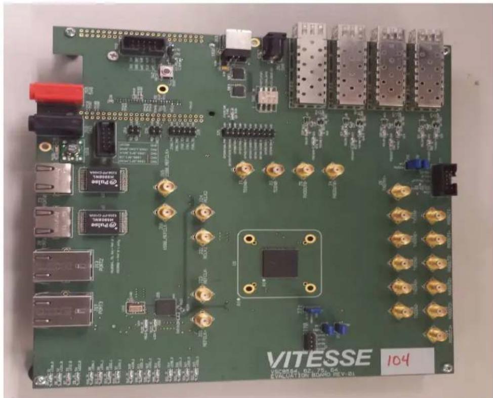
natural_image
Green printed circuit board with various electronic components and connectors (no readable text or symbols)1.1 References
The following reference documents provide additional information about the operation of the VSC8584 evaluation board.
• VSC8564 Datasheet
( https://www.vitesse.com/products/product.php?number=VSC8564 )
• VSC8582 Datasheet
( https://www.vitesse.com/products/product.php?number=VSC8582 )
• VSC8575 Datasheet
( https://www.vitesse.com/products/product.php?number=VSC8575 )
• VSC8584 Datasheet
( https://www.vitesse.com/products/product.php?number=VSC8584 )
- IEEE1588v2 and SyncE – Applications and Operation Using Vitesse's Synchronization Solution
( http://www.vitesse.com/products/download.php?fid=4767&number=VSC8574 )
• VSC8584 GUI
( https://www.vitesse.com/products/product.php?number=VSC8584 )
2 General Description
The evaluation board in Figure 1 provides the user a way to evaluate the VSC8584 device in multiple configurations. Four RJ-45 connectors are provided for copper media interfaces. The four SFP cages allow for evaluation of the fiber media interconnects. The MAC interface is provided via SMA connectors.
For access to all of the features of the device, an external microcontroller is used to configure the on-board clock chip via a two wire serial bus and the VSC8584 via the MDIO bus. The graphical user interface (GUI) enables the user to access the registers.
The evaluation board uses a Zarlink device to synthesize a 125MHz reference clock signal from a 20MHz crystal which serves as the REFCLK input.
2.1 Key Features
2.1.1 Copper Port RJ45 Connections
PHY Ports 2 and 3 use UDE RTA 1648BAK1A with integrated magnetic while PHY Ports 0 and 1 use generic RJ45 connectors with discrete Pulse H5008 magnetics.
2.1.2 SGMII/QSGMII MAC SMA
SGMII SMA connections are provided for all PHYs while the QSGMII SMA connection is available only on PHY0.
2.1.3 Switch Block Control
Set the SW1 switch as shown in the figure below.
Figure 2. SW1 Switch Control

text_image
SW1 REFCLKSEL COMA_MODE CLK_SQUELCH2.1.4 Zarlink ZL30343 SyncE G.8262/SETS
The Zarlink ZL30343 is initialized by default to provide a 125MHz differential LVPECL clock to VSC8584 REFCLK inputs. (Note: the ZL30343 can be programmed to provide LVDS differential clock in conjunction with an LVDS termination provided for REFCLK, please refer to the Zarlink manual for programming its output drive.)
Also, the ZL30343 can support synchronization with the VSC8584 PHY recovered clock for SyncE operation. The ZL30343 is initialized to lock to a recovered clock output if one is enabled and available from the VSC8584 PHY. If no recovered clock signal is available, then the ZL30343 will select the crystal oscillator (U16) as default reference source for holdover operation. ZL30343 will indicate locked versus holdover status by driving LED D33 or D34. See the Zarlink documentation for more discussion concerning its operation. See the VSC8584 datasheet for configuring recovered clock output pin behavior.
Please ensure three-way resistive connections R19 and R22 are appropriately connected to feedback the VSC8584's recovered clock outputs into the ZL30343 device, if synchronization to a recovered clock source is desired.
2.1.5 External 1588 Clock Option
The user may choose to provide an external 1588 REFCLK via SMA connections to J65 and J66. Zero Ohm jumpers may need to be removed and or installed to connect via these clock inputs. The board is built with connections for external 1588 REFCLK, unless otherwise indicated in documentation accompanying the specific board delivered.
2.1.6 External RefClk Option
The user may choose to provide an external PHY REFCLK via SMA connections to J21 and J23. Zero Ohm jumpers may need to be removed and or installed to connect via these clock inputs. As per section 2.1.4 and unless otherwise indicated in documentation accompanying the specific board, the board is built with a REFCLK connection driven by the ZL30343, instead of using an external REFCLK source.
2.1.7 1588 Daisy-Chain SPI Time-Stamping Connection
The VSC8584 device enables daisy-chaining multiple devices to reduce the number of pins required to transmit time stamping information to system ASICs gathering IEEE 1588 time stamps. For users with two or more 8584EV boards, the following single-ended connections shown below are required from the master device to slave device:
• J75 pin 6 to J77 pin 6 (1588_SPI_CLK output → input)
• J75 pin 4 to J77 pin 4 (1588_SPI_CS output → input)
• J75 pin 2 to J77 pin 2 (1588_SPI_MISO output → 1588_SPI_MOSI input)
See section 3.5.4 for register programming to enable this interface.
Recommendation: for SPI daisy chaining use a Molex 10 pin ribbon cable with one-to-one connections.
Figure 3. 1588 Daisy-Chain SPI Interconnect
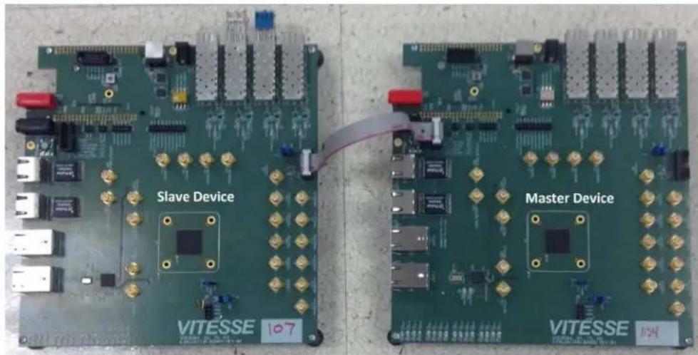
text_image
Slave Device VITESSE 107 Master Device VITESSE 107Once enabled along with proper initialization of the 1588 IP block, time-stamped 1588 traffic in the egress direction will generate a similar sequence on the serialized timestamp daisy-chain as shown in Figure 4. See the VSC8584 datasheet section about Serial Time Stamp Output Interface for a more detailed functional description.
Figure 4. 1588 Daisy-Chain SPI Traffic Pattern (PHY port 3 egress)
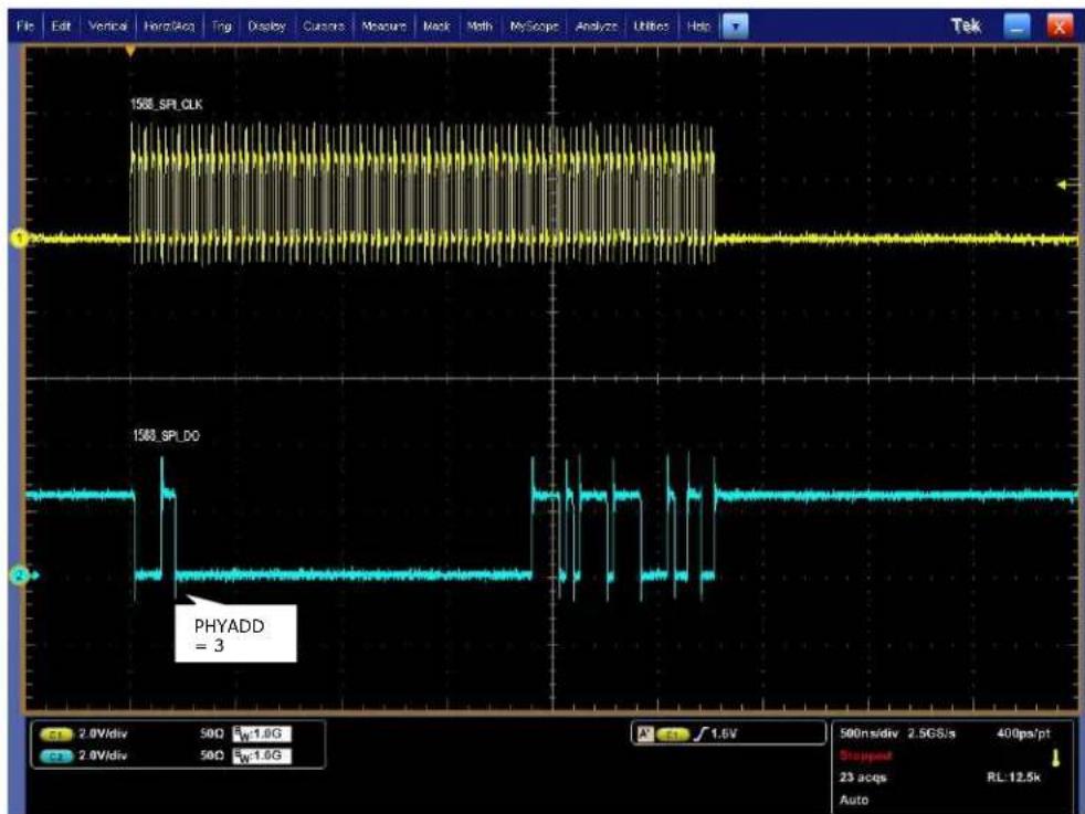
line
| Signal | Value | | ------------ | ----- | | 1508_SPL_CLK | High-frequency oscillations | | 1508_SPL_DO | Low-frequency oscillations | | PHYADD | 3 |2.1.8 Network Interface Microcontroller Card
A "Rabbit" microcontroller card is included to facilitate a software interface to the registers on the VSC8584. The controller card has a hard coded static IP address. Refer to the label on the card for the value. This address is required by the user to initiate communications via the board and the GUI.
NOTE: The factory programmed Rabbit board IP address is: 10.9.70.193.
3 Quick Start
3.1 Connecting the Power Supply
The evaluation board uses +5VDC to power the on-board regulators creating the +3.3V, +2.5V, and +1.0V rails which drive the devices as well as modules. The evaluation board can be powered up using the power pack which provides the +5VDC. Simply plug the AC adaptor into a wall socket and the barrel end into J67 (see the upper right corner of Figure 1). Immediately the user should see several LEDs turn on.
The user may alternately connect the board to a bench style power supply by connecting the red banana plug to +5VDC and the black banana plug to ground. If the supply provides 3A the board should come alive as described above.
3.2 PC Software Installation
- Download the ZIP file to the PC's root directory, normally C:.
- Extract to C:\
- Double click the icon to launch the GUI (It is acceptable to drag the icon to the desktop)
3.3 Connecting the Board to the PC
The Rabbit board can interface with a PC either through a direct connection to the PC or if configured properly through a local area network. The latter option requires the user to configure the Rabbit's IP address so as to properly reside on the user's network.
The IP address of the board should be written on the Rabbit network interface daughter board card. The default value should be 10.9.70.193. You will need to use this IP address to initially access the board for operation or to change its IP address.
3.3.1 Changing the IP Address of the Board
- Determine and write down the new unique IP address you wish to change the board to.
- Directly connect an Ethernet cable from a PC to the Rabbit board. NOTE: Some older PCs do not support auto-crossover on the Ethernet connection so a cross-over cable may be needed.
- Launch a DOS command window by clicking on the Start->Run button and typing "cmd".
- Within the DOS command window type "Telnet".
- In Telnet, connect to the Rabbit board's address using the open command by typing "open^10.9.70.XXX".
- 10.9.70.xxx where xxx is the value on your board from the factory (typically 193).
- You should have a prompt and be able to type help to get a list of commands available on the Rabbit.
a) If you are unable to connect, then most likely you will need to change the IP address of the connected PC to have the first 3 octets similar to the board by following the subsequent steps.
b) On the PC under Windows -> Control Panel -> Network Connections -> Local Area Connection, right mouse click for Properties. Under the General tab highlight Internet Protocol (TCP/IP) and click on Properties. From there enter the new PC IP address such as 10.9.70.yyy where yyy is a unique value and NOT the same as the Rabbit board. Once complete, return to step 4.
- Command the board to change its IP address to the new one by typing into Telnet now connected to the board the command: set ip
where is in the form xxx.xxx.xxx.xxx. Once you hit the IP address will be changed and the Rabbit will save the value and reboot which
may take approximately 1 minute. The Telnet session will disconnect from the board.
-
Change your PC IP address to the same IP network as the Rabbit board.
-
Telnet to the Rabbit board.
-
Use the following commands to complete configuration of the Rabbit board:
a) set netmask xxx.xxx.xxx.xxx
b) set gateway xxx.xxx.xxx.xxx
c) save env
-
Please record and inform Vitesse of the new IP address of the board when you return so that Vitesse can connect to and reconfigure the board.
-
Re-label the Rabbit board with the new IP.
3.4 Using the Control Software
Connect the VSC8584EV Rabbit microcontroller RJ-45 directly to the PC or through a network switch if properly configured. Apply +5VDC to the EVB.
Launch the GUI by double-clicking the GUI shortcut located in C:\ViperGUI_4_67 or on the desktop if it has been moved there. The GUI Connection window shown in Figure 5 should appear.
VSC8584 Evaluation Board User Guide
Figure 5. GUI Connection Window

text_image
Viper EvalBoard (v 4.67) VSC8584 MII Registers Extended MII Registers Extended2 MII Registers Extended3 MII Registers Clause 45 DVAD:3 registers Clause 45 DVAD:7 registers Micro Page Registers Connection Setup Run PHY Script CPU Command Log Register Dumps Matlab Interface Log PHY Access : Rabbit SMI Genie Rabbit 10.9.70.183 Connected COM COM1 Managed Connect DisconnectTo make a connection to the EVB, click "Rabbit" and enter the IP address of the EVB, then click on "Connect". The display next to the IP address window should change to "Connected". If it does not, check the IP address, or your network configuration until connection with the EVB can be successfully established.
Double-click on "MII Registers" and the window shown in Figure 6 should appear:
Figure 6. MII Registers GUI Window

text_image
VSCB584 - MII Registers Reg 0 - Mode Control Reg 1 - Mode Status Reg 2 - PHY Identifier Register #1 Reg 3 - PHY Identifier Register #2 Reg 4 - Auto Negotiation Advertisement Reg 5 - Auto Negotiation Link Partner Ability Reg 6 - Auto Negotiation Expansion Reg 7 - Auto Negotiation Next Page Transmit Reg 8 - Auto Negotiation Link Partner Next Page Reg 9 - 1000BASE-T Control Reg 10 - 1000BASE-T Status Reg 11 - Reserved Reg 12 - Reserved Reg 13 - MMD Access Control Reg 14 - MMD Address or Data Reg 15 - 1000BASE-T Status Extension #1 Reg 16 - 100BASE-TX Status Extension Reg 17 - 1000BASE-T Status Extension #2 Reg 18 - Bypass Control Reg 19 - Error Counter #1 Reg 20 - Error Counter #2 Reg 21 - Error Counter #3 Reg 22 - 10BASE-T Control & Status Reg 23 - Extended PHY Control #1 Reg 24 - Extended PHY Control #2 Reg 25 - Interrupt Mask Reg 26 - Interrupt Status Reg 27 - MAC Interface Auto-negotiation Control & Reg 28 - Auxiliary Control and Status Reg 29 - Led Mode Select Reg 30 - LED Behavior Reg 31 - Extended Page Access PHY 0 Comments hex ▼ 1040 Read Write Restore Defaults 15 □ Software Reset 14 □ Loopback 13 □ Forced Speed Selection Bit 0 12 ▼ Auto Negotiation Enable 11 □ Power Down 10 □ Isolate 9 □ Restart Auto Negotiation 8 □ Duplex Mode 7 □ Collision Test Enable 6 ▼ Forced Speed selection Bit 1 5 □ Reserved 4 □ Reserved 3 □ Reserved 2 □ Reserved 1 □ Reserved 0 □ Reserved bin ▼ None bin ▼ None bin ▼ None bin ▼ None bin ▼ NoneVerify the device is up and running by reading MII Register 0. It should read back 0x1040. Reading back all 0's or all 1's indicates a problem. A checked box means the bit is set to "1," if unchecked it is "0".
3.4.1 Board Initialization and Running PHY Scripts
Once the evaluation board connectivity has been established and confirmed, the PHY should be initialized. Initialization can be accomplished by running an init-script sequence, such as performed by the pre- and post-reset functions of the PHY API standalone app.
While the init-script sequence may not require for specific operational modes, an init-script sequence is highly recommended to ensure correct performance over the greatest set of user scenarios for the PHY. After initialization is performed, refer to
VSC8584 Evaluation Board User Guide
the PHY Datasheet section on Configuring of the PHY and PHY Interfaces for the desired application.
In order to execute an init-script, double-click on "Run PHY Script" within the GUI Connection Window to launch the Run PHY Script window as shown in Figure 7. This enables a user to load a script to configure the device rather than navigating through Registers pages. Click "Load" button, browse to a desired script file via the pop-up panel, finally click "Run" button. After execution is completed, you should see read-back values in decimal as shown in Figure 8.
The script syntax is command, phy address (in decimal), register address (in decimal), and register content (in either hexadecimal or decimal).
Figure 7. Run PHY Script GUI Window (after script is loaded)

text_image
VSC85B4 - Run PHY Script PHY Command Sequence smiwrite 0 31 4 smiwrite 0 17 133 smiwrite 0 18 0 smiwrite 0 16 45088 smiwrite 0 17 133 smiwrite 0 18 0 smiwrite 0 16 47136 // slave only - global smiwrite 0 31 4 smiwrite 0 26 0xc0f7 Load Run ClearFigure 8. Run PHY Script GUI Window (after script is executed)
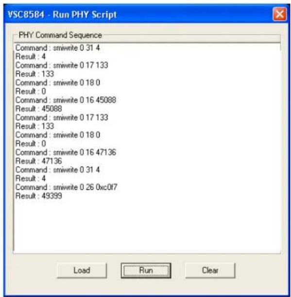
text_image
VSC8584 - Run PHY Script PHY Command Sequence Command: smiwrite 0 31 4 Result: 4 Command: smiwrite 0 17 133 Result: 133 Command: smiwrite 0 18 0 Result: 0 Command: smiwrite 0 16 45088 Result: 45088 Command: smiwrite 0 17 133 Result: 133 Command: smiwrite 0 18 0 Result: 0 Command: smiwrite 0 16 47136 Result: 47136 Command: smiwrite 0 31 4 Result: 4 Command: smiwrite 0 26 0xc0f7 Result: 49399 Load Run Clear3.4.2 Copper Media Operation (1000BASE-T)
A single register write and some external coax cables enables 1G Ethernet traffic to be received by the VSC8584 RJ-45 port, routed through the VSC8584 and externally via coax loopback cables through the SGMII interface and transmitted back to the traffic source on the same copper port. First configure the SerDes in SGMII mode by writing to Micro page 18'd. This is a global setting and does not need to be applied per port.
Steps for external SGMII loopback:
- Set up the Copper traffic source (i.e., IXIA or Smartbits)
- Connect an Ethernet cable to an RJ-45 Port 0.
- Connect two matched coax cables, J1 - J4 and J2 - J5.
- Write using the "Micro Page Registers" window: 18'd 0x80F0.
- When "Micro Page" 18'd is read back, bit 15 will clear.
- Linkup bit is in MII Reg 1, bit 2 (MII 1.2), read twice to update
Traffic should be flowing.
Steps for SGMII forwarding port 0 ↔ port 1:
- Set up the Copper traffic source (i.e., IXIA or Smartbits)
-
Connect one Ethernet cable to RJ-45 Port 0, second cable to RJ-45 Port 1.
-
Connect four matched coax cables as follows:
J1 <TDIN0+> to J6 <RXDOUT1+>
J2 <TDIN0-> to J7 <RXDOUT1->
J5 <RXDOUT0-> to J10 <TXDIN1->
J4 <RXDOUT0+> to J9 <TXDIN1+>
- Write using the "Micro Page Registers" window: 18'd 0x80F0.
- When "Micro Page" 18'd is read back, bit 15 will clear.
- Linkup bit is in MII Reg 1, bit 2 (MII 1.2), read twice to update
Traffic should be flowing.
3.4.3 Fiber Media Operation (1000BASE-X)
Follow all steps in section 3.4.2 with fiber media connection to (IXIA) and add the following steps.
- Write using the "Micro Page Registers" window: 18'd 0x8FC1. (Global)
- When "Micro Page" 18'd is read back, bit 15 will clear.
- Write "MII Register" (PHY 0) 23'd 0x0204 (Sets Media Mode)
- Write "MII Register" (PHY0) 0'd 0x9040 (SW Reset for media mode setting to have effect)
- Write "Extended MII Register" (PHY0) 19'd 0x0001 (Flip SIGDET polarity if necessary)
- Write "MII Register" (PHY0) 0'd 0x0004 (Disable Auto Neg if necessary)
Traffic should be flowing.
3.4.4 Fiber Media Operation (100BASE-FX)
Follow all steps in section 3.4.2 with fiber media connection to (IXIA) and add the following steps.
- Write using the "Micro Page Registers" window: 18'd 0x8FD1. (Global)
- When "Micro Page" 18'd is read back, bit 15 will clear.
- Write "MII Register" (PHY 0) 23'd 0x0304 (Sets Media Mode)
- Write "MII Register" (PHY0) 0'd 0x9040 (SW Reset for media mode setting to have effect)
- Write "Extended MII Register" (PHY0) 19'd 0x0001 (Flip SIGDET polarity if necessary)
- Write "MII Register" (PHY0) 0'd 0x0004 (Disable Auto Neg if necessary)
Traffic should be flowing.
3.5 Useful Registers
3.5.1 Ethernet Packet Generator
ExtMII 29E is the Ethernet Packet Generator register. Refer to the datasheet for configuration options.
A Good CRC packet counter is in ExtMII 18.13:0. A read of the register reads back the good CRC packets and then clears the register so the subsequent reads will be 0 if no traffic has been received. If traffic has been received since the last read, bit 15 will be set.
3.5.2 Copper PHY Error Counters
Idle errors = MII 10.7:0
RX errors = MII 19.7:0
False carrier = MII 20.7:0
Disconnects = MII 21.7:0
CRC errors = ExtMII 23.7:0
3.5.3 Fiber PHY Error Counters
Good RX CRC packets = Ext3MII 28.13:0
Bad RX CRC packets = Ext3MII 29.7:0
Good TX CRC packets = Ext3MII 21.13:0
Bad TX CRC packets = Ext3MII 22.7:0
3.5.4 Configuring 1588 Daisy-Chain SPI Time-Stamping
For Master VSC8584EV, run these instructions for each port 0-3, as indicated by the "phy" variable below:
smiwrite phy 31 4
smiwrite phy 17 133
smiwrite phy 18 0
smiwrite phy 16 45088
smiwrite phy 17 133
smiwrite phy 18 0
smiwrite phy 16 47136
smiwrite phy 31 0
Note the accesses above can be pasted into a text file and loaded via the customer GUI "Run PHY Script" feature, after substituting the desired port number 0-3 for "phy" above.
For Slave VSC8584EV, run the same instructions listed above for Master VSC8584EV for each port 0-3. Then, run the following write only on port 0:
smiwrite 0 31 4
smiwrite 0 26 0xc0f7
smiwrite 0 31 0
4 Additional Information
For any additional information or questions regarding the device(s) mentioned in this document, contact your local sales representative.