JX2127CH - Microwaves GE - Free user manual and instructions
Find the device manual for free JX2127CH GE in PDF.

User questions about JX2127CH GE
0 question about this device. Answer the ones you know or ask your own.
Ask a new question about this device
Download the instructions for your Microwaves in PDF format for free! Find your manual JX2127CH - GE and take your electronic device back in hand. On this page are published all the documents necessary for the use of your device. JX2127CH by GE.
USER MANUAL JX2127CH GE
Installation Built-In Trim Kits Instructions JX2127 and JX2130
Questions? Call GE Answer Center at 800.626.2000 or Visit our Website at: www.GEAppliances.com
BEFORE YOU BEGIN
Read these instructions completely and carefully.
- IMPORTANT – Save these instructions for local inspector's use.
- IMPORTANT – Observe all governing codes and ordinances.
- Note to Installer – Be sure to leave these instructions with the Consumer.
- Note to Consumer – Keep these instructions for future reference.
- For easier installation and personal safety, we recommend that two people install this microwave oven.
- Unplug the microwave oven before attempting installation of this kit.
FOR YOUR SAFETY:
⚠ WARNING – Before beginning the installation, switch power off at service panel and lock the service disconnecting means to prevent power from being switched on accidentally. When the service disconnecting means cannot be locked, securely fasten a prominent warning device, such as a tag, to the service panel.
TOOLS YOU WILL NEED

2 Phillips screwdriver

Pencil

Awl or punch

Drill with 764 " bit or #35
Scissors (optional)
Tape measure
- Skill level – Installation of this appliance requires basic mechanical and electrical skills.
• Completion time - 1-3 hours - Proper installation is the responsibility of the installer.
- Product failure due to improper installation is not covered under the Warranty.
- This kit is UL listed for installation alone or over any General Electric/Hotpoint/RCA single electric wall oven.
PARTS INCLUDED
| PART QUANTITY | ||
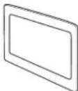 | Trim Frame 1 | |
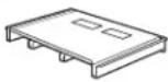 | Bottom Duct 1 | |
 | Top Bracket 1 | |
 | Phillips Round-Head 24 Screws | (22 for installation) |
 | Phillips Flat-Head 5 Screws (4 required for installation) | |
 | Anti-Tip Bracket 1 | |
 | Bottom Bracket 1 | |
 | Template 1 | |
required
1 CUTOUT DIMENSIONS
| Models 27"30" | ||
| Height 16 | 34''16 | 34'' |
| Width 25 | 12''25 | 12'' |
| Depth (min.)* 19 | 12'' or 22"19 | 12'' or 22" |
* Min. depth with receptacle outside cabinet 19½" Min. depth with receptacle inside cabinet 22"
text_image
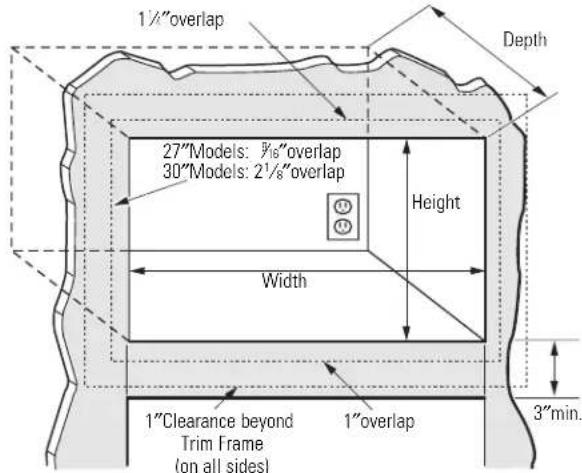
1½"overlap 27"Models: Ⅲ/6"overlap 30"Models: 2½"overlap Height Width 3"min. 1"Clearance beyond Trim Frame (on all sides) 1"overlapCAUTION
This trim kit uses air flow from the top, bottom and sides of the trim frame. Blocking the air flow can cause the microwave to function improperly and may cause damage to the microwave.
Allow a 1" clearance beyond the edge of the Trim Frame to provide proper air flow.
On 27" models, allow 1 ¼" at the top, %6" on the sides and 1" at the bottom for overlap of the Trim Frame over the edges of the cutout.
On 30" models, allow 1 ¼" at the top, 2 ½" on the sides and 1" at the bottom for overlap of the Trim Frame over the edges of the cutout.
2 INSTALL BOTTOM BRACKET AND BOTTOM DUCT
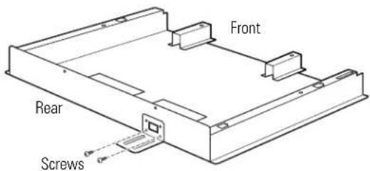
A Fit the tab on the bottom bracket into the slot on the back of the bottom duct, and push down until the bracket is flush with the bottom of the duct. Fasten the bottom bracket to the bottom duct by using two bronze round-head screws.
B Disconnect the microwave oven before proceeding with the installation.
text_image
Front Rear ScrewsC Remove any loose items inside the microwave oven, including the turntable and turntable support. Carefully turn the microwave oven upside down.
D Line up the tabs on the bottom duct with the slots on the bottom of the microwave and insert the tabs into the slots. Secure the bottom duct with four bronze round-head screws as shown.
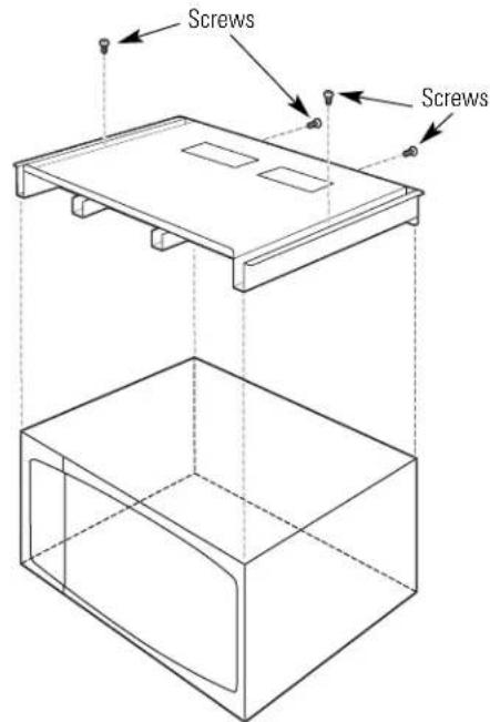
text_image
Screws ScrewsMicrowave Oven Upside Down
3 INSTALL THE ANTI-TIP BRACKET
A Draw a line on the cutout floor at the center of the cutout, and extend the line 12 " down the face of the cabinet.
B Fold or cut the front edge of the template, along the front guide line. Place the template flush along the front edge of the cutout floor, aligning the center line of the template with the center line of the cutout floor. Mark the centers of the two screw holes with an awl or center punch for the anti-tip bracket location as shown.

natural_image
Pure 3D geometric diagram showing a rectangular prism with internal lines and an arrow, no text or symbols present.Cutout Floor
C Remove the template and drill two holes for the anti-tip bracket.
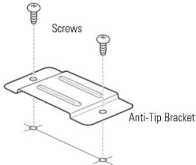
text_image
Screws Anti-Tip BracketD Install the anti-tip bracket onto the cutout floor using two bronze round-head screws.
4 INSTALL MICROWAVE OVEN INTO CABINET
A Slide the microwave oven part way into the cabinet opening.
B Plug in the microwave oven.
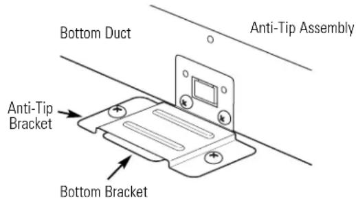
text_image
Bottom Duct Anti-Tip Assembly Anti-Tip Bracket Bottom BracketC The bottom bracket must be flat to the cutout floor to engage correctly with the anti-tip bracket as shown. Carefully slide the microwave oven back, engaging the anti-tip bracket. Make sure the power cord is not mashed or cut as you slide the microwave into place.
D Center the microwave oven within the cutout opening.
E Ensure the microwave oven is accurately centered. Line up the center line on the cabinet with the triangular hole on the front of the bottom duct.
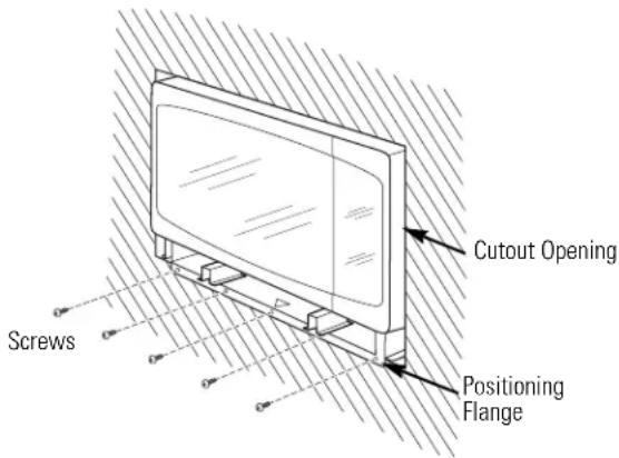
text_image
Screws Cutout Opening Positioning FlangeF Drill pilot holes through the positioning flange and then install five bronze round-head screws at the front of the bottom duct as shown.
5 INSTALL THE TOP BRACKET
A Place the top bracket on the top of the microwave oven, with the tabs on the top and sides of the bracket fitting squarely against the microwave oven.
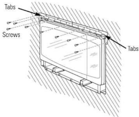
text_image
Tabs Screws TabsB Drill pilot holes through the holes in the top bracket. Attach the top bracket to the cabinet using nine bronze round-head screws.
6 INSTALL THE TRIM FRAME
A Place the trim frame over the microwave oven.
B Snap the two spring clips on the trim frame into the slots on the top bracket.
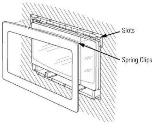
text_image
Slots Spring ClipsC Open the microwave oven door. Secure the trim frame using four flat-head screws (two on the inside top and two on the inside bottom).

text_image
Flat-head screws Flat-head screws7 REPLACE ANY LOOSE ITEMS
A Your trim kit is now fully installed. Replace any loose items that were removed from the inside of the microwave oven. Save or discard the extra screws. Do not place them in the microwave oven.
B Keep these installation instructions for future reference.
C Replace house fuse or close circuit breaker to restore power at the service panel.
164D3370P328
49-40398
06-03 JR