O6MDP2W - Security Camera Speco Technologies - Free user manual and instructions
Find the device manual for free O6MDP2W Speco Technologies in PDF.

User questions about O6MDP2W Speco Technologies
0 question about this device. Answer the ones you know or ask your own.
Ask a new question about this device
Download the instructions for your Security Camera in PDF format for free! Find your manual O6MDP2W - Speco Technologies and take your electronic device back in hand. On this page are published all the documents necessary for the use of your device. O6MDP2W by Speco Technologies.
USER MANUAL O6MDP2W Speco Technologies
Network Camera Web Setup Manual
Version 1.4
Table of Contents
1 Connecon and Login....1
1.1 Network Connecon....1
1.2 Log in....1
2 Live View....3
2.1 Stream Setup ....3
2.2 Funcon Menu....4
2.3 Live View Display Adjustment ....5
2.3.1 Image Adjustment ....5
2.3.2 Original Size 6
2.3.3 Full Screen....6
2.3.4 Width and Height Rao 6
2.3.5 Fluency Adjustment....6
2.3.6 Rules Info 6
2.3.7 Zoom and Focus....6
2.4 Fisheye Live View 8
3 PTZ Control 9
3.1 Scan/Tour/Paern/Pan 10
3.2 Preset....10
3.3 Go To....11
4 Playback....12
4.1 Playback....12
4.1.1 Play Controls....13
4.1.2 Playback File 14
4.1.3 Playback Cut....16
4.1.4 Record Type 16
4.1.5 Progress Bar....16
4.1.6 Assistant Funcon....17
4.1.7 Image Playback....17
5 Setup....18
5.1 Basic Setup....18
5.1.1 Image Setup....18
5.1.2 Video Setup....29
5.1.3 Audio....33
5.2 Network Setup....34
5.2.1 IP Address Setup 34
5.2.2 Connecon....35
5.2.3 PPPoE....36
5.2.4 DDNS Client....37
5.2.5 IP Filtering....37
5.2.6 SMTP (Email) 38
5.2.7 UPnP 39
5.2.8 SNMP 40
5.2.9 Mulcast....42
5.2.10 802.1x 43
5.2.11 QoS....43
5.2.12 HTTPS 44
5.3 Event Setup....53
5.3.1 Video detecon ....53
5.3.2 Audio Detecon....56
5.3.3 Smart Plan....59
5.3.4 Intelligent Video 59
5.3.5 Face Detecon....65
5.3.6 Heat Map 66
5.3.7 Alarm....69
5.3.8 Abnormality 69
5.4 Storage Management....72
5.4.1 Schedule....72
5.4.2 Desnaon 74
5.4.3 Record control 77
5.5 System....78
5.5.1 General 78
5.5.2 User Admin 80
5.5.3 Factory Default 83
5.5.4 Import/Export 83
5.5.5 Upgrade 84
5.6 Informaon....85
5.6.1 Version....85
5.6.2 Log....85
5.6.3 Online User 86
Note
The instrucons in this manual apply to the following models.
Connect the camera to a network and run the IP Scanner tool. IP Scanner can search for the device on the local network. The camera is set to DHCP mode by default.
Open up IP Scanner. In the device list, you can view the IP address, model number, and MAC address of each device. Select the applicable device and double click to open up the web viewer.
See Figure 1-1.
| Refresh | Open Web Page | Login... | IP | Restart | Factory Default | Information | About |
| Status | Name | IP Address | MAC Address | Version | |||
| Online | O2D4M | 192.168.56.128 | 00:07:18:FF:03:73 | 1.0.57 | |||
| Online | O2D4 | 192.168.56.143 | 5C:F2:07:1C:28:CA | 1.0.53 | |||
| Online | VIP2PTZ1ZX | 192.168.56.157 | 00:07:D8:17:8A:68 | 1.3.7-X1_release | |||
| Online | VIP2D1M | 192.168.56.149 | 5C:F2:07:20:9D:AD | 2.5.0-T3_release | |||
| Online | OSMDP1 | 192.168.56.139 | 5C:F2:07:1C:3E:66 | 1.0.47 | |||
| Online | Eddie-O2DP8 | 192.168.56.104 | 5C:F2:07:1C:1F:74 | 1.0.47 | |||
| Online | OSMDP1 | 192.168.56.124 | 5C:F2:07:1C:23:D8 | 1.0.47 | |||
| Online | O2DP9 | 192.168.56.147 | 5C:F2:07:1C:74:16 | 1.0.54 | |||
| Online | O81 | 192.168.56.105 | 5C:F2:07:1C:01:3B | ||||
| Online | OPTZ36XI | 192.168.56.140 | 5C:F2:07:1C:03:1D | ||||
| Online | n/a | 192.168.56.130 | 5C:F2:07:24:00:1A | 2236.0.0.1412190 | |||
| Online | n/a | 192.168.56.14 | 5C:F2:07:24:03:C2 | 2236.0.0.1409180 | |||
| Online | n/a | 192.168.56.12 | 5C:F2:07:24:51:2E | 2218.0.0.1409180 | |||
| Online | O2VLB2 | 192.168.56.146 | 4C: 11:BF:8A:23:64 | ||||
Figure 1-1
1.2 Log in
Open Internet Explorer and input network camera address in the address bar or double click the device in IP Scanner.
If it's the rst me accessing the camera, the browser may request to install the Acve-X plug-in. This is required to view live video in the browser. Go ahead and follow the steps to install the plug-in.
The login interface is shown as below. See Figure 1-2.
Please input your user name and password.
Default user name is admin and password is 1234.
Note: For security purposes, please change the password aer initial login.

text_image
speco technologies® Username: Password: Login CancelFigure 1-2
There will be a prompt shown to recommend changing the default password. For direct conneccon installations on Speco's plug and play NVRs with built-in PoE ports, please leave the password as default. For other installaons, it is highly recommended to change the password for security purposes.

text_image
For security purposes, it is recommended to change the password. New Password Weak OK Strong Confirm Password Don't show me again Ok CancelFigure 1-3
2 Live View
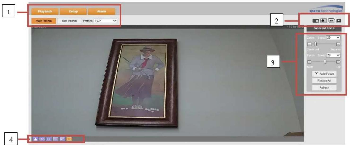
Aer logging in, the live view screen will be shown. See Figure 2-1.
text_image
1 Playback Setup Alarm Main Stream Sub Stream Protocol TCP speco technologies 2 192.8x 1 Zoom and Focus Zoom Speed 20 Zoom out Zoom in Focus Speed 20 Auto Auto Focus Restore All Refresh 3 4Figure 2-1
There are four seconds:
● Secon 1: System menu and stream selecon
● Secon 2: Funcon menu (snapshot, digital zoom, etc)
● Secon 3: PTZ and zoom control menu (oponal)
● Secon 4: Live view display adjustment controls
2.1 Stream Setup
Note: Some models do not have a second sub stream (Sub Stream 2). The setup interface is shown in Figure 2-2.

text_image
Main Stream Sub Stream 1 Sub Stream 2 Protocol TCPFigure 2-2
Please refer to the following table for detailed informaon.
| Parameter | Funcon |
| Main stream | Click it to enable main stream video monitoring and click again to disable it. |
| Sub Stream 1 | Click it to enable Sub Stream1 video monitoring and click again to disable it. |
| Sub Stream 2 | Click it to enable Sub Stream 2 video monitoring and click again to disable it. |
| Protocol | You can select the streaming protocol from the dropdown list.There are three opons: TCP/UDP/MulcastTCP is the default. |
2.2 Funcon Menu
The funcon menu interface is shown in Figure 2-3.

text_image
1 2 3 4 5 6 7 8Figure 2-3
Please refer to the following table for detailed informaon.
| Parameter | Funcon | |
| 1 | Relay-out | If there is alarm output, status descripon is as follows:● Red: means there is alarm output.● Grey: means alarm has nished.Click on the buon to force alarm to be on or o. |
| 2 | Digital Zoom | ● Click to enable digital zoom.● Le-click and drag to dene a zone. Within the digitally zoomed image, drag the mouse for digital pan/lt funcon.Right-click to return to the original image.● Scroll buon on the mouse can also be used for digital zoom. |
| 3 | Snapshot | Click on the buon to take a snapshot. Image will be saved to the path that's dened in setup |
| 4 | Triple Snapshot | Click on the buon to take 3 snapshots. Images will be taken at one image per second. |
| 5 | Easy focus | Displays two parameters for focusing: AF Peak and AF Max.AF Peak: Displays the video denion during the focus process.AF Max: opmal value for video denion.The closer AF Peak and AF Max are to each other, the beer the focus eect is. |
| 7 | Audio | Toggle audio. |
| 8 | Talk | Toggle push to talk. |
| 9 | Help | Opens the help window. |
2.3 Live View Display Adjustment
The interface is shown as in Figure 2-4.

text_image
1 2 3 4 5 6 7 100% W+ +oFigure 2-4
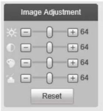
2.3.1 Image Adjustment
See Figure 2-5 for image adjustment.
text_image
Image Adjustment + 64 + 64 + 64 + 64 + 64 ResetFigure 2-5
Click the buon to display/hide the image control interface on the top right pane.
Please refer to the following table for detailed informaon.
| Parameter | Funcon | ||
| Video setup |  | Brightness | Note:● All operaons here apply to web live view only.● Please go to Setup -> Basic Setup -> Image Setup to adjust the parameters on the camera itself. |
 | Contrast | ||
 | Hue | ||
 | Saturaon | ||
| Reset | Restore to system default setup. | ||
2.3.2 Original Size
Click this buon to display the actual resoluon size of the stream.
2.3.3 Full Screen
Click to go to full-screen mode. Double click the mouse or press the Esc buon on the keyboard to exit full screen.
2.3.4 Width and Height Rao
Click to display in the original rao or ll the display window.
2.3.5 Fluency Adjustment
Depending on the network bandwidth, priority could be given to how the stream is delivered. The uency mode prioritizes the video quality over me lag. The realme mode prioritizes real-me streaming over video quality so it will try to minimize network lag as much as possible. Normal mode is balanced and is the default mode.
2.3.6 Rules Info
Displays any rule that has been set for analycs.
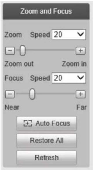
2.3.7 Zoom and Focus
Click to display the interface shown in Figure 2-6. Focus is triggered by zoom and will adjust automacally. The focus can be adjusted manually as well or with the Auto Focus funcon.
text_image
Zoom and Focus Zoom Speed 20 - + Zoom out Zoom in Focus Speed 20 - + Near Far Auto Focus Restore All RefreshFigure 2-6
| Parameter | Funcon |
| Zoom | Adjust the focal length of the lens by clicking or long pressing “+”“-”buons.Speed is used to adjust the length of one step for a single click. |
| Focus | Adjust the focus by clicking or long pressing“+”、“-” buons.Speed is used to adjust the length of one step for a single click. |
| Auto-focus | Click to adjust the focus automacally.Note:Other lens operaons are not allowed during this process. |
| Reset All | Resets the lens to zero posion to eliminate any errors of the lens. This is normally used if many zoom adjustments have been done over me and the image quality is not clear. |
| Refresh | Synchronize the locaon of the slider bars aer hardware zoom focusing. |
2.4Fisheye Live View (if equipped)
This secon applies to O6MDP2 only. In live view, the interface shown in Figure 2-7 will be shown on the right side of the window.

text_image
Install Mode Display ModeFigure 2-7
Note: The dewarping modes shown here in live view only aects what's being seen in the web viewer only. To change the actual dewarped mode of the stream itself, it must be rst congured in Setup. See secon 5.1.1.7.
Live view mode can be used to help set up the desired install and viewing modes. Install modes include ceiling, wall, and ground. Display modes include various dewarped images.
3 PTZ Control
See

text_image
4011Kbps 192.0x1.08.0 PTZ Control Joystick Speed(1-8) 5 Zoom + Focus + Iris + PTZ Settings Scan Start StopFigure 3-1 for PTZ controls.
| Parameter | Note |
| PTZ direcon | ● PTZ supports eight direcons: le/right/up/down/upper le/upper right/boom le/boom right. |
| Speed | The higher the value, higher the speed. Applies to pan, It, zoom, focus and iris. |
 Quick Posion Quick Posion | Use mouse to draw a box of interest in the image. The camera will rotate and zoom to the region. |

text_image
4011Kbps 192.0x108.0 PTZ Control Joystick Speed(1-8): 5 Zoom + Focus + Irs + PTZ Settings Scan Start StopFigure 3-1
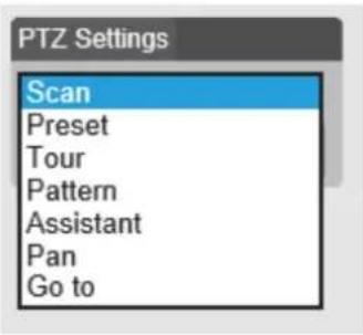
PTZ sengs interface is shown in Figure 3-2.
text_image
PTZ Settings Scan Preset Tour Pattern Assistant Pan Go toFigure 3-2
3.1 Scan/Tour/Paern/Pan (if equipped)
The interface is shown in Figure 3-3. Enter applicable values for tour and pattern. Click on start to begin the funcon and stop to end the funcon.

text_image
PTZ Settings Scan Start StopFigure 3-3
3.2 Preset (if equipped)
Preset interface is shown in Figure 3-4. Enter the preset value and press Go to.

text_image
PTZ Settings Preset 1 1~80 Go toFigure 3-4
3.3 Go To
Go to interface is shown in Figure 3-5. Enter the horizontal angle, vercal angle, and zoom posion to go to that exact posion.
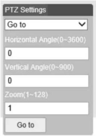
text_image
PTZ Settings Go to Horizontal Angle(0~3600) 0 Vertical Angle(0~900) 0 Zoom(1~128) 1 Go toFigure 3-5
4 Playback
Recordings on the SD card can be accessed through the web browser.
Note
Before playback, the SD card must be properly installed and congured. Refer to secon 5.4 for detailed instrucons.
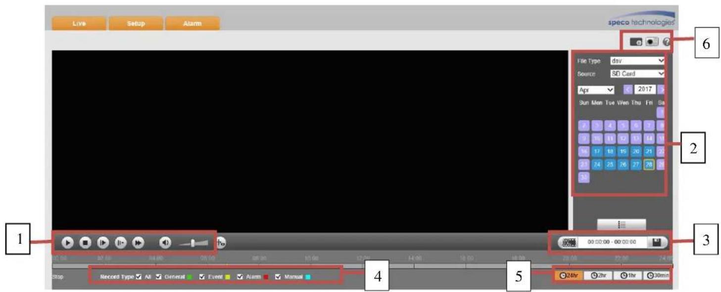
4.1 Playback
The SD card playback interface is shown in Figure 4-1.
text_image
Live Setup Alarm speco technologies File Type: day Source: SD Card Apr 2017 Sun Mon Tue Ven Thu Fri Sa 2 3 4 5 6 7 8 0 10 11 12 13 14 15 16 17 18 19 20 21 22 21 24 25 26 27 28 29 30 Record Type: All General Event Alarm Manual Stop 00:00:00 - 00:00:00 24hr 2hr 1hr 30minFigure 4-1
There are four seconds:
- Secon 1: Play controls
● Secon 2: Recorded data - Secon 3: Cut funcon
● Secon 4: Recording type
● Secon 5: Progress bar - Secon 6: Additional funcons
4.1.1 Play Controls
The control funcons are shown in Figure 4-2 and Figure 4-3.

text_image
① ② ③ ④ ⑤ ⑥ ⑦Figure 4-2

text_image
① ② ③ ④ ⑤ ⑥ ⑦Figure 4-3
| Parameter | Funcon |
| 1 Play | Press to start playing |
| 2 Stop | Press to stop playing |
| 3 Play by frame | Press to go to the next frame.Note:Recording will be paused while this funcon is in use. |
| 4 Slow | Press to slow play |
| 5 Fast Forward | Press to fast forward |
| 6 Audio mute | Toggle audio mute |
| 7 Volume | Adjust audio volume |
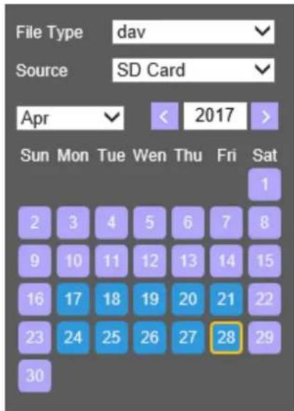
4.1.2 Playback File
In the calendar, dates highlighted blue have recorded data. See Figure 4-4.
text_image
File Type dav Source SD Card Apr < 2017 > Sun Mon Tue Wen Thu Fri Sat 1 2 3 4 5 6 7 8 9 10 11 12 13 14 15 16 17 18 19 20 21 22 23 24 25 26 27 28 29 30Figure 4-4
| Parameter | Funcon |
| File Type | Select “dav” for video playback.Select “jpg” for picture playback. |
| Data Source | Default is SD card. |
Step 1. Click on a date highlighted in blue. The me bar will display recorded data. Green represents connuous recording, yellow represents moon recording, red represents sensor recording, and blue represents manual recording.
Step 2. Click on a specific me to start playback from that me. See Figure 4-5.

text_image
00:00 02:00 04:00 06:00 08:00 10:00 12:00 14:00 16:00 18:00 20:00 22:00 24:00Figure 4-5
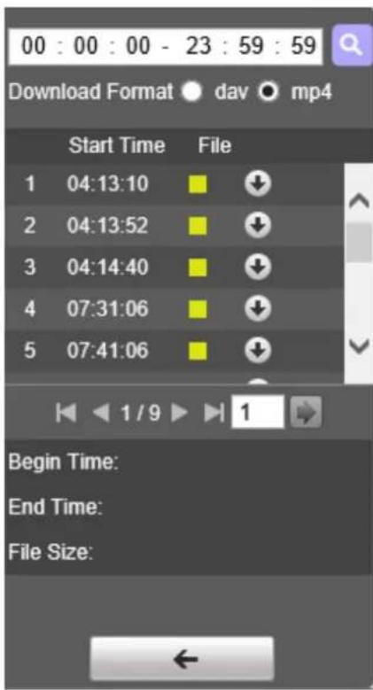
Step 3. Click on le list buon to list all available les for the selected date.
Step 4. Double click on a le in the list to start playback for this le. The le size, start me and end me will be displayed.
text_image
00 : 00 : 00 - 23 : 59 : 59 Download Format dav mp4 Start Time File 1 04:13:10 2 04:13:52 3 04:14:40 4 07:31:06 5 07:41:06 Begin Time: End Time: File Size:Figure 4-6
| Parameter | Funcon |
 Search Search | Search for recordings within the specied start me and end me for the date. |
| Download Format | Two formats are available for download: dav and mp4. |
 Download Download | Click to download to the specied path. Path can be specied in Setup->Basic Setup->Video Setup->Path.The system does not support download and playback at the same me. |
 Back Back | Click to go back to the calendar interface. |
4.1.3 Playback Cut
Note:
Playback cut funcon will automatically pause playback as cut and playback cannot be performed at the same me.
Step 1. Click on a me on the me bar.
Step 2. Click on the cut icon to set the selected me as the start me.
Step 3. Click on another me for the end me.
Step 4. Click on the cut icon to set the end me.
Step 5. Click on the Save buon to save the le. See Figure 4-7.

text_image
00:00:00 - 00:00:00Figure 4-7
4.1.4 Record Type
Only the selected recording type will be shown on the me bar. See Figure 4-8.

text_image
Record Type ✓ All ✓ General ✓ Motion ✓ Alarm ✓ ManualFigure 4-8
4.1.5 Progress Bar

Figure 4-9
| Parameter | Funcon |
| Changes the me bar to show a period of 24 hours | |
| Changes the me bar to show a period of the past 2 hours | |
| Changes the me bar to show a period of the past 1 hour | |
| Changes the me bar to show a period of the past 30 minutes |
4.1.6 Assistant Funcon
Video playback assistant funcon is shown in Figure 4-10.

Figure 4-10
| Parameter | Funcon |
 Digital Zoom Digital Zoom | Enable rst and then click and drag on any area to digitally zoom in. Right mouse click to restore to the original size.Mouse scroll buon can also be used. |
 Snapshot Snapshot | Click to save a snapshot for the video currently in playback. |
4.1.7 Image Playback
See Figure 4-11 for the image playback interface. Under the le type dropdown menu, select "jpg" to switch to the interface.

text_image
Live Setup Alarm speco technologies File Type: pg Source: SD Card May 2017 Sun Mon Tue Wed Thu Fri Sat 1 2 3 4 5 6 7 8 9 10 11 12 13 14 15 16 17 18 19 20 21 22 23 24 > 26 27 28 29 30 31 Snapshot Type All General Event AlarmFigure 4-11
5 Setup
To congure camera seings, from the live view screen, click on the "Setup" buon at the top le.
5.1 Basic Setup
5.1.1 Image Setup
Note:
Available opons may vary depending on the camera model.
5.1.1.1 Picture
Step 1
Select "Basic Setup > Image Setup > Picture" as shown in Figure 5-1.

text_image
Camera Configuration Image Setup Profile Management Zoom and Focus speco technologies Basic Setup > Video Setup > Image Setup > Audio Setup Network Setup Event Setup Storage Setup System Information Live Default Refresh Save Profile: Day Picture Exposure Backlight WB Day & Night IR Light Brightness 50 Contrast 50 Saturation 50 Sharpness 50 Gamma 50 Mirror ON OFF Flip 180°Figure 5-1
Step 2
Set picture parameters; please refer to the following table for more details.
| Parameter | Note |
| Brightness | Adjusts the image brightness. The image may become blurry if the value is set too high. |
| Contrast | Adjusts the image contrast. Dark areas become darker and bright areas become overexposed if the value is set too high. The image may become blurry if the value is set too low. |
| Saturaon | Adjusts the color saturaon. The color becomes darker when the value is increased. If the value is set too low, the image will look black and white. This does not aect the overall brightness of the image. |
| Sharpness | Adjusts the sharpness level of the edge on the image. Increasing the sharpness will also increase image noise. |
| Gamma | Changes the image brightness and improve the dynamic display range of the image. |
| Mirror | Flips the image horizontally. |
| Flip | Changes the display direcon of the image.90°: Rotates the image clockwise 90°270°: Rotates the image counter-clockwise 90°180: Flips the image vercally.Note:Set the main stream resoluon to 1920x1080 to use the ip funcon. |
Step 3
Click "Save" to save the sengs.
5.1.1.2 Exposure
Step 1
Select "Basic Setup > Image Setup > Exposure" as shown in Figure 5-2.
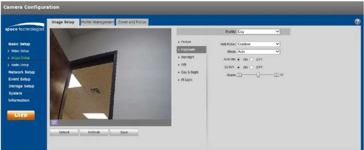
text_image
Camera Configuration speco technologies Basic Setup > Video Setup > Image Setup > Audio Setup Network Setup Event Setup Storage Setup System Information Live Image Setup Profile Management Zoom and Focus Profile Day ▶ Picture ▶ Exposure ▶ Backlight ▶ IWB ▶ Day & Night ▶ IR Light Anti-flicker Outdoor Mode Auto Auto Ims ON OFF 3D NR ON OFF Grade 50 Default Refresh SaveFigure 5-2
Step 2
Set exposure parameters; please refer to the following table for more details.
| Parameter | Note |
| An-icker | ● Outdoor● 50Hz● 60Hz (used in the United States) |
| Mode | Camera exposure modeNote:● When “An-icker” is set to “Outdoor”, the “exposure mode” can be set as “gain priority” or “shuer priority” mode.The opons are:● Auto: image brightness is adjusted automacally according to the environment.● Gain priority: The device can adjust automacally according to the gain range set during normal exposure range in dierent scenes.● Shuer priority: The device can adjust automacally according to the shuer range set during normal exposure range in dierent scenes.● Manual: Set the gain value and shuer value manually. |
| Auto Iris | ● The lens iris can auto adjust the size according to the environment aer auto iris is enabled, then the image brightness will change accordingly.● The iris value reaches the max when disabling auto iris, the lens iris will not change according to the environment brightness. |
| 3D NR | Mulple frames are processed and then noise is reduced by using the interframe informaon between the previous and the laer frame. |
| Grade | This can be applied when 3D NR is enabled.Increase the value for a bigger eect. |
Step 3
Click "Save" to save the sengs.
5.1.1.3 Backlight
Backlight mode opons are BLC, WDR and HLC.
- BLC: compensates for high backlight areas behind a subject to make the subject more visible.
- WDR: balances washed out image with a large dynamic range. Typically used for lobbies, where the camera is poinng towards the door.
- HLC: reduces exposure from bright light sources such as headlights. This can be applied in areas such as toll gates, entrance and exit of the parking lots, etc.
Step 1
Select "Basic Setup > Image Setup > Backlight", which will display the interface shown in Figure 5-3.
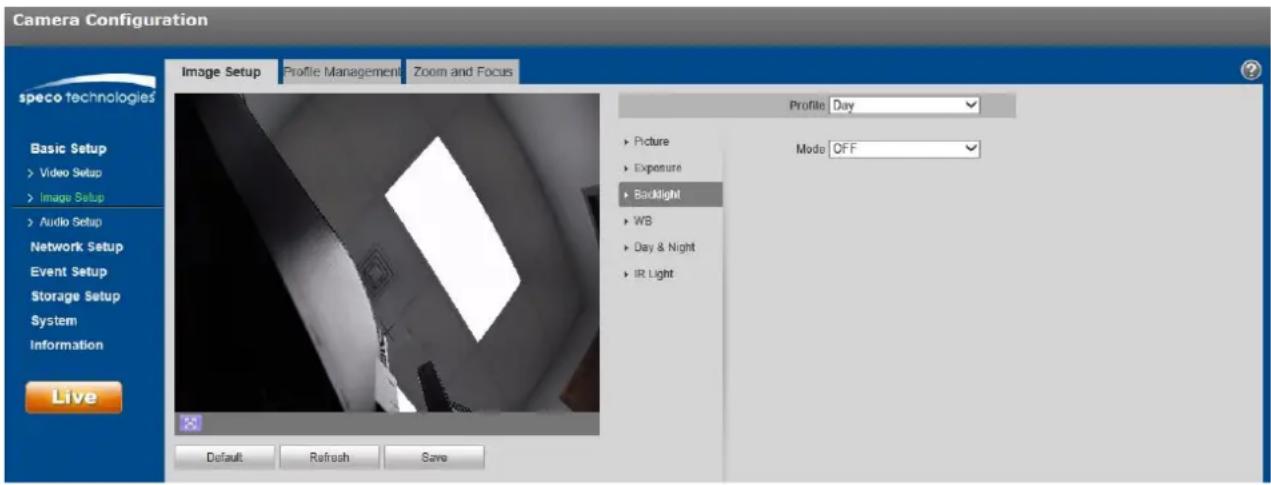
text_image
Camera Configuration speco technologies Basic Setup > Video Setup > Image Setup > Audio Setup Network Setup Event Setup Storage Setup System Information Live Image Setup Profile Management Zoom and Focus Profile Day ► Picture ► Exposure ► Backlight ► WB ► Day & Night ► IR Light Mode OFF Default Refresh SaveFigure 5-3
Step 2
Set the backlight parameter.
● BLC can be set to default mode or customized mode.
When "Default" mode is selected, the system adjusts automacally to the environment, to make the darkest part of the image to be seen.
When “Customized” mode is selected, a custom area in the image can be selected, to compensate for that area.
- When set to “WDR”, the system will lower the brightness of the area with high brightness and enhance the brightness of the area with low brightness. This is very helpful in situations such as the camera in a lobby poinng towards the entrance, where there is a lot of light coming in.
Note:
There may be video loss of a few seconds when the camera is switched from non WDR mode to WDR mode.
- When set to "HLC", the system will reduce the high brightness areas and decrease the size of the halo area.
Step 3
Click "Save" to save the sengs.
5.1.1.4 WB
WB (white balance) is used to adjust colors in the image so that objects that appear white in person are shown as white in the camera.
Step 1
Select "Basic Setup > Image Setup > WB", which will display the interface shown in Figure 5-4.

text_image
Camera Configuration speco technologies Basic Setup > Video Setup > Image Setup > Audio Setup Network Setup Event Setup Storage Setup System Information Live Image Setup Profile Management Zoom and Focus Profile Day Picture Exposure Backlight WB Day & Night Light Mode Auto Default Refresh SaveFigure 5-4
Step 2
Set the mode.
- When set to "Auto", the system will compensate automacally for the white balance depending on the environment.
- When set to "Natural", the system will compensate based on natural light sengs.
- When set to "Street Lamp", the system will compensate based on an outdoor scene at night.
- When set to "Outdoor", the system will compensate based on most outdoor scenes with natural light and arcial light.
- When set to "Manual", red gain and blue gain values can be set manually.
- When set to "Regional Custom", a custom area can be dened in the image, which the system can then compensate for the dierent color temperatures of the images in the area.
Step 3
Click "Save" to save the sengs.
5.1.1.5 Day & Night
This is to set up color and monochrome switching.
Step 1
Select "Basic Setup > Image Setup > Day & Night", shown in Figure 5-5.

text_image
Camera Configuration speco technologies Image Setup Profile Management Zoom and Focus Basic Setup > Video Setup > Image Setup > Audio Setup Network Setup Event Setup Storage Setup System Information Live Default Retrench Save Profile: Day Picture Exposure Backlight WB Day & Night IR Light Mode: Auto Sensitivity: Low Delay: 63Figure 5-5
Step 2
To set the day & night parameters, refer to the following table for more details.
| Parameter | Note |
| Mode | ● Color: The camera image is always displayed in color.● Auto: The camera switch automacally between color and black & white, depending on the light level.● Black & white: The camera image is always displayed in black & white. |
| Sensitivity | The parameter can be set when the “Day/Night Mode” is set to “Auto”.Higher sensitivity means that the mode will switch back and forth from color and black and white more easily. |
| Delay | The parameter can be set when the “Day/Night Mode” is set to “Auto”.This is to set a delay for switching between modes. This may be helpful in situaons such as light ickering. |
Step 3
Click "Save" to save the sengs.
5.1.1.6 IR Light
IR LEDs can be controlled in this secon.
Step 1
Select "Basic Setup > Image Setup > IR Light", shown in Figure 5-6.
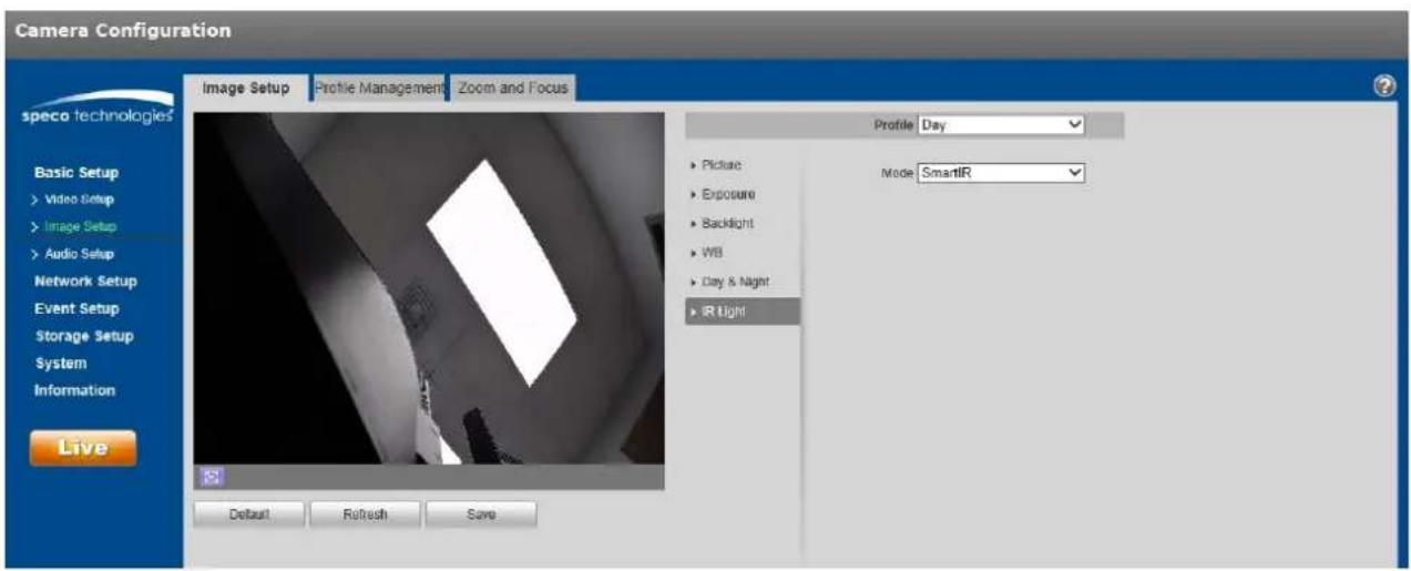
text_image
Camera Configuration Image Setup Profile Management Zoom and Focus Profile Day Basic Setup Video Setup Image Setup Audio Setup Network Setup Event Setup Storage Setup System Information Live Default Refresh Save Picture Exposure Backlight WB Day & Night IR Light Mode SmartIRFigure 5-6
Step 2
Set the mode.
- When set to "Manual", the brightness of the IR LEDs can be set manually.
- When set to "Smart IR", the system will adjust the LED brightness according to the actual scene.
- When set to "O", IR LEDs will not operate even in darkness.
Step 3
Click "Save" to save the sengs.
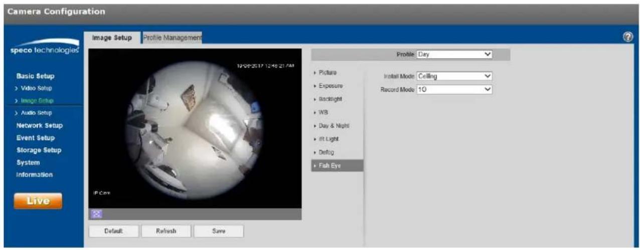
5.1.1.7 Fisheye Setup
SecureGuard® VMS and the N32NX NVR is able to dewarp the sheye view from the O6MDP2 IP camera model. For other recording opons, the camera itself can be congured to send out a dewarped image in the stream itself.
Step 1
Select "Basic Setup > Image Setup > Fisheye". See Figure 5-7.
text_image
Camera Configuration speco technologies Basic Setup > Video Setup > Image Setup > Audio Setup Network Setup Event Setup Storage Setup System Information Live Image Setup Profile Management 19:00-20:17 12:46:21:AM IP Core Profile Day Picture Exposure Backlight WB Day & Night at Light Debug Fish Eye Install Mode Ceiling Record Mode 10 Default Refresh SaveStep 2
Select the desired parameters. Descripon are listed in the table below
| Parameter | Funcon |
| Installaon Mode | Three installaon modes are available:Ceiling, wall, and ground.The orientaon of the image will vary depending on the mode. |
| Record Mode | When a specic record mode is set, the output stream will be the dewarped image on the mode that was set. This is helpful for situaons where a recorder does not have the ability to dewarp the image.Aer seng the mode, click Save to change to that view.Available record modes will vary according to the dierent installaon modes.1O: Original sheye image. Note: Any opon other than “1O” will cause the sheye viewing opon to be hidden in live view.1P: 360°rectangular panoramic image.2P: Available for “Ceiling” or “Ground”. Displays two 180°rectangular images.1O+3R: original image + 3 independent sub images. All images support digital zoom and pan, which can be done in live view.1R: 1 independent sub image.2R: 2 independent sub images.4R: 4 independent sub images. |
5.1.1.8 Prole Management
Image sengs can be set to dierent values depending on the prole that's being used.
Step 1
Select "Basic Setup > Image Setup > Prole Management" to display the "Prole Management" tab.
Step 2
Set the prole.
- When set to "Normal", the system will monitor according to the normal conguraon.

text_image
Camera Configuration speco technologies Image Setup Profile Management Zoom and Focus Profile Management Normal Full Time Schedule Default Refresh Save Basic Setup > Video Setup > Image Setup > Audio Setup Network Setup Event Setup Storage Setup System Information LiveFigure 5-8
- When set to "Full Time", the prole can be set to always use the Day conguraon or the Night conguraon.
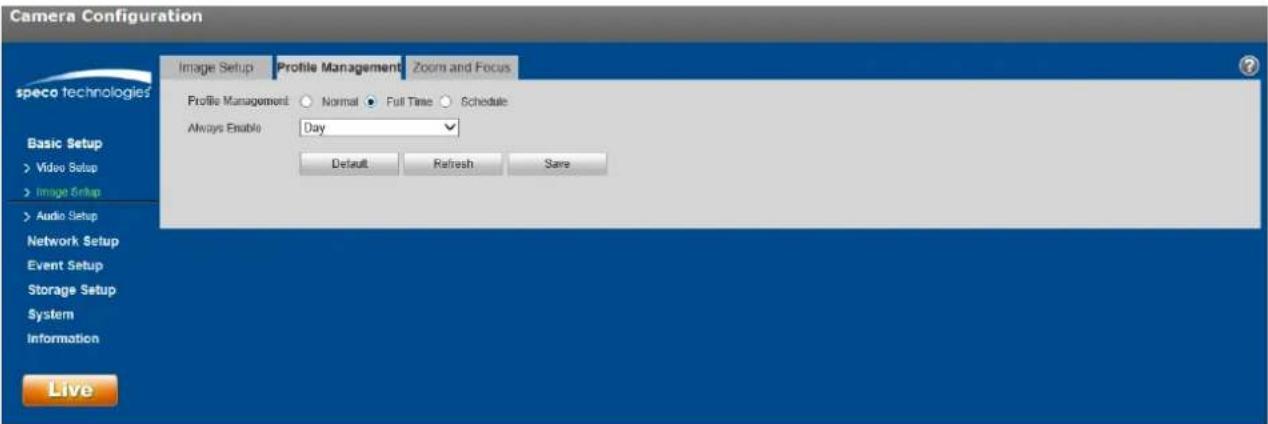
text_image
Camera Configuration Image Setup Profile Management Zoom and Focus Profile Management: Normal Full Time Schedule Always Enable Day Default Refresh Save Live speco technologies Basic Setup > Video Setup > Image Setup > Audio Setup Network Setup Event Setup Storage Setup System InformationFigure 5-9
- When set to "Schedule", a specied period of the day can be used for the Day conguraon and the rest of the day for the Night conguraon. Click and slide the bar to set the me period.
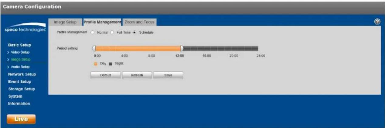
text_image
Camera Configuration Image Setup Profile Management Zoom and Focus speco technologies Basic Setup > Video Setup > Image Setup > Audio Setup Network Setup Event Setup Storage Setup System Information Live Image Setup Profile Management Normal Full Time Schedule Period setting 0:00 4:00 8:00 12:00 16:00 20:00 24:00 Day Night Default Refresh SaveFigure 5-10
Step 3
Click "Save" save the sengs.
Note:
Click "Default" to restore the device to the default sengs. Click "Refresh" to check the latest conguration of the device.
5.1.1.9 Zoom and Focus
Note:
This applies to only models with motorized lens.
Step 1
Select "Basic Setup > Image Setup > Zoom and Focus", shown in Figure 5-11.
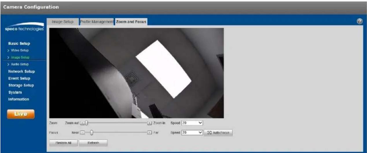
text_image
Camera Configuration speco technologies Basic Setup > Video Setup > Image Setup > Audio Setup Network Setup Event Setup Storage Setup System Information Live Image Setup Profile Management Zoom and Focus Zoom Zoom out Zoom in Speed 20 Focus Near Far Speed 20 Auto Focus Restore All RefreshFigure 5-11
Step 2
The focal length can be set by pressing "+" or "-" for Zoom or dragging the slider bar. Adjust the speed as desired.
Step 3
Focus can be adjusted manually, by pressing "+" or dragging the slider block.
Note:
- Click "Auto Focus" to adjust the focus automacally aer a manual adjustment.
- If the image fails to focus aer a few mes of adjustment, click "Restore All" to reset the lens and remove the accumulave errors of the lens.
5.1.2 Video Setup
5.1.2.1 Video
Step 1
Select "Basic Setup > Video Setup > Video" shown in Figure 5-12.
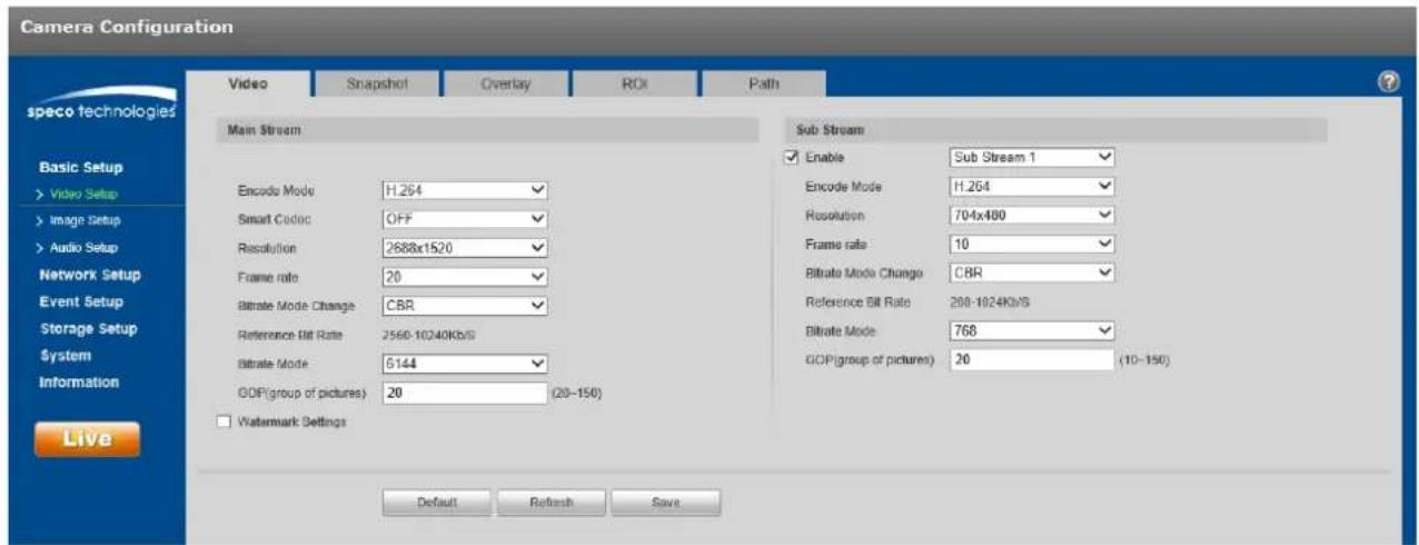
text_image
Camera Configuration speco technologies Video Snapshot Overlay ROI Path Main Stream Sub Stream Enable Sub Stream 1 Encode Mode H.264 Resolution 704x480 Frame rate 10 Bitrate Mode Change CBR Reference Bit Rate 2560-10240Kb/S Bitrate Mode 5144 GDP(group of pictures) 20 (20-150) GDP(group of pictures) 20 (10-150) Watermark Settings Basic Setup > Video Setup > Image Setup > Audio Setup Network Setup Event Setup Storage Setup System Information Live Default Refresh SaveFigure 5-12
Step 2
Refer to the following table for more details on seng the video stream parameters.
| Parameter | Funcon |
| Sub Stream Enable | Select “Enable” to enable the sub stream.Depending on the model, there may be a second sub stream available. |
| Encode mode | Select the compression to be used.Opons are H.264, MJPEG, and H.265 (depending on the model) |
| Resoluon | Mulple resoluon opons are available for each stream.Resoluon is the equivalent to the size of the image. Higher minimum bit rate is required for higher resoluons. |
| Frame Rate | Select the applicable frame rate for each stream, measure in fps (frames per second). |
| Bit Rate Mode | CBR (constant) means that bitrate will be kept at a constant value even with various changes in the scene. VBR (variable) means that bitrate will be adjusted according to the scene changes. |
| Reference Bit Rate | Recommended bit rate range based on the resoluon. |
| Bit Rate | Set the bit rate value. Note that higher bit rate provides a beer image quality, but also results in more storage usage. |
| SVC (scalable video coding) | SVC can dynamically adjust the stream based on the network conditions. Can be turned on or o depending on the client being used. |
| GOP (group of pictures) | Determines how many P frames are allowed in between two I frames. I frame is the beginning frame of a unique scene. A GOP value of frame rate x 2 or lower is recommended. |
| Watermark Sengs | Check to enable watermarking on the video. |
| Watermark Character | Enter the watermark text to be used for vericaon. |
Step 3
Click "Save" to save the sengs.
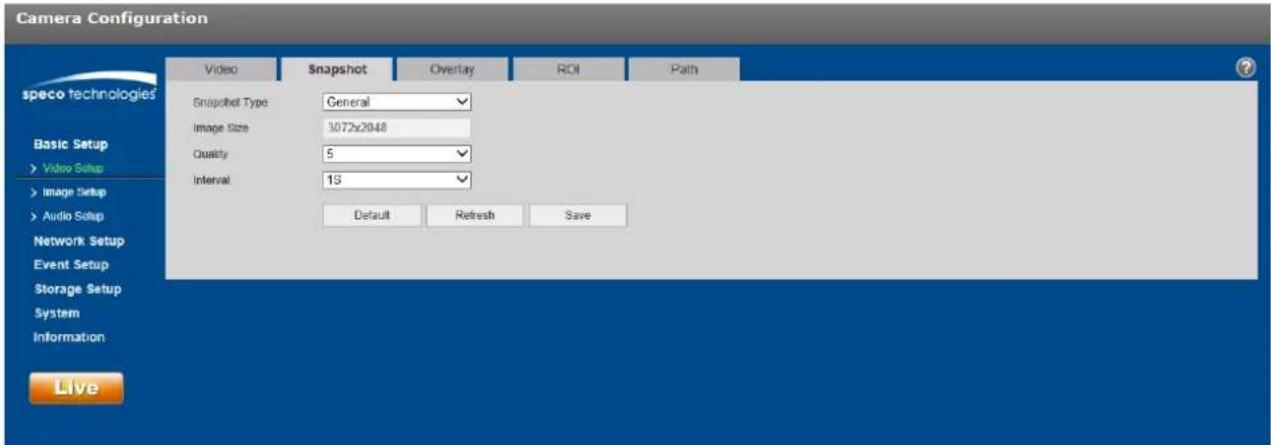
5.1.2.2 Snapshot
The snapshot interface is shown as in Figure 5-13.
text_image
Camera Configuration speco technologies Basic Setup > Video Setup > Image Setup > Audio Setup Network Setup Event Setup Storage Setup System Information Live Video Snapshot Overlay ROI Path Snapshot Type: General Image Size: 3072x2048 Quality: 5 Interval: 13 Default Refresh SaveFigure 5-13
Please refer to the following sheet for detailed informaon.
| Parameter | Funcon |
| Snapshot type | There are two modes: General (schedule-based) and Event (alarm-based). |
| Image size | Same resoluon as the main stream resoluon. |
| Quality | Sets the image quality, with 6 being the highest quality. |
| Interval | Interval of how many seconds between snapshots. |
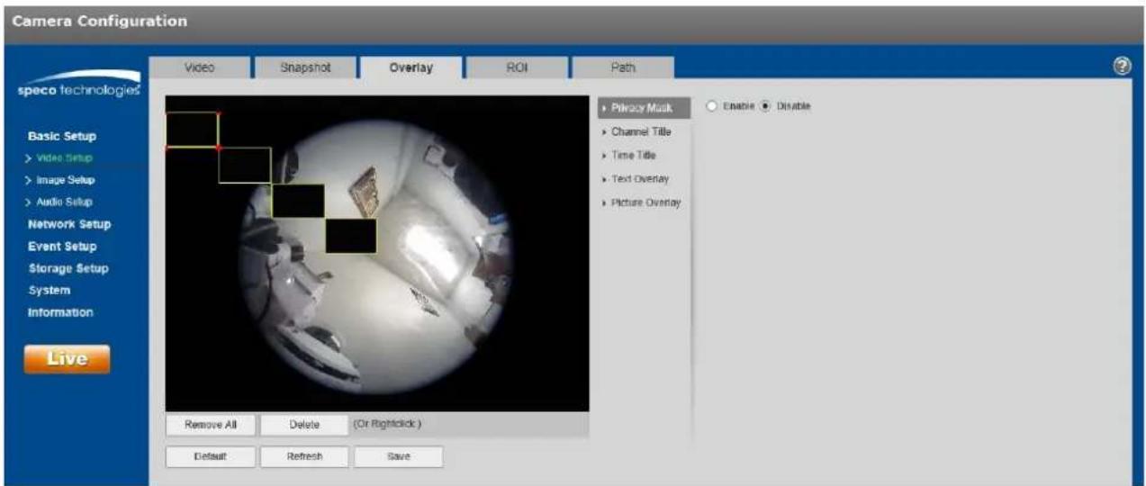
5.1.2.3 Video Overlay
Figure 5-14 shows the OSD opons.
text_image
Camera Configuration Video Snapshot Overlay ROI Path speco technologies Basic Setup > Video Setup > Image Setup > Audio Setup Network Setup Event Setup Storage Setup System Information Live Remove All Delete (Or Rightclick) Default Refresh Save Privacy Musk Channel Title Time Title Text Overlay Picture Overlay Enable DisableFigure 5-14
Please refer to the following sheet for detailed informaon.
| Parameter | Funcon |
| Privacy Masking | Up to 4 privacy mask zones can be dened.Privacy mask blocks out the image in the dened areas. |
| Time Title | Time informaon can be shown in the video if enabled.The posion can be changed by dragging it with the mouse |
| Channel Title | This shows the nickname of the device/channel on the screen.Posion can be changed with the mouse. |
| Text Overlay | User-dened text can be displayed.Posion can be changed with the mouse. |
| Picture Overlay | An image can be set as an overlay onto the stream.Requirements for picture uploading are listed in the secon.Note:Text overlay and picture overlay cannot be used at the same me. |
5.1.2.4 ROI (Region of Interest)
Check "Enable" and use the mouse to denote the desired region. Click "Save" to save the sengs. See Figure 5-15.

text_image
Camera Configuration speco technologies Basic Setup > Video Setup > Image Setup > Audio Setup Network Setup Event Setup Storage Setup System Information Live Video Snapshot Overlay ROI Path Enable Disable Image Quality 6 Remove All Delete (Or Rightstick) Default Refresh SaveFigure 5-15
5.1.2.5 Path
Error! Reference source not found.16 shows the interface for seng up storage paths for snapshots and recordings.
There are 4 types of save paths:
• Live view snapshot
- Playback snapshot
- Playback clip download
- Playback video cut download (within playback, a clip with a specific me period can be dened to be downloaded)
Click the Save buon to save the setup.

text_image
Camera Configuration speco technologies Live Snapshot C:\Users\David\WebDownload\LiveSnapshot Browse... Playback Snapshot C:\Users\David\WebDownload\PlaybackSnapshot Browse... Playback Download C:\Users\David\WebDownload\PlaybackRecord Browse... Video Clips C:\Users\David\WebDownload\VideoClips Browse... Default Save LiveFigure 5-16
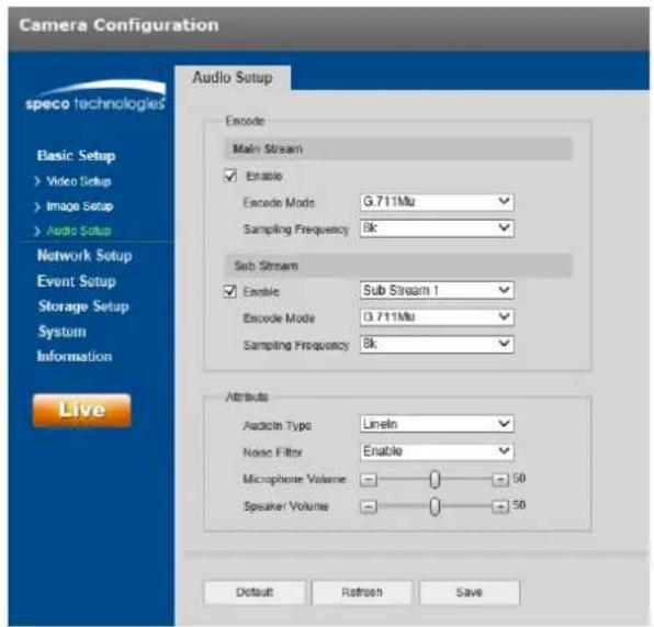
5.1.3 Audio
Applies only to models with audio capability.
The audio interface is shown in Figure 5-17.
text_image
Camera Configuration Audio Setup speco technologies Basic Setup Video Setup Image Setup Audio Setup Network Setup Event Setup Storage Setup System Information Live Encode Main Stream Enable Encode Mode G.711Mu Sampling Frequency 8k Sub Stream Enable Sub Stream 1 Encode Mode D.711Mu Sampling Frequency 8k Attributes Audio Type Lineln Noise Filter Enable Microphone Volume 50 Speaker Volume 50 Default Retrosch SaveFigure 5-17
Please refer to the following sheet for detailed informaon.
| Parameter | Funcon |
| Enable | Audio can be enabled only when the video stream is enabled.. |
| Encode mode | Select the applicable compression between G.711A, G.711Mu, G.726, and AAC.This applies to both the audio input and 2-way audio. |
| Sampling Frequency | Opons are 8k, 16k, 32k, and 48k. |
| AudioIn Type | Device needs to connect to an external audio input source under Line In mode. It does not need to connect to an external audio input source under Mic mode. |
| Noise Filter | Enable to Iter relevant noise. |
| Microphone Volume | Adjust the microphone volume from 0~100. |
| Speaker Volume | Adjust the speaker volume from 0~100. |
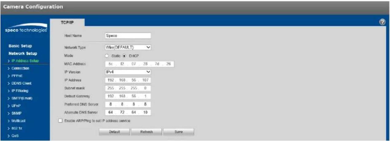
5.2 Network Setup
5.2.1 IP Address Setup
For IP address setup, IPv4 and IPv6 are both supported. IPv4 supports stac IP and DHCP. IPv6 supports stac IP only. If the IP address is modified, the web viewer will automatically jump to the new IP address.
text_image
Camera Configuration speco technologies TCP/IP Host Name Speco Network Type Wire(DEFAULT) Mode Static DHCP MAC Address 5c 12 07 28 7d 26 IP Version IPv4 IP Address 192 100 56 107 Subnet mask 255 255 255 0 Default Gateway 192 168 56 1 Preferred DNS Server 8 8 8 8 Alternate DNS Server 64 72 64 10 Enable ARP/Ping to set IP address service Default Refresh SaveFigure 5-18
Please refer to the following sheet for detailed informaon.
| Parameter | Funcon |
| Host Name | Set the device name. Maximum of 15 characters is supported. |
| Network Type | Default is wired. |
| Mode | Select between stac and DHCP. If seng to stac, make sure that the network does have stac IP addresses available for use. When using DHCP, make sure that the network has the capability to assign an IP address to the device. Typically, a residential or commercial router will have a built-in DHCP server. |
| Mac Address | Displays the Mac address of the device. |
| IP Version | Select IPv4 or IPv6. |
| IP Address | Can be modified if in stac mode. |
| Subnet Mask | Dene the subnet mask. For a typical case, the mask is 255.255.255.0. |
| Default Gateway | Dene the gateway of the network. Example: if the IP address is 192.168.1.150, the gateway will be 192.168.1.1. |
| Preferred DNS | DNS IP address. |
| Alternate DNS | Alternate DNS IP address. |
| Enable ARP/Ping set device IP address service. | This can be used to modify or set the device IP address by utilizing the Mac address.Before the operaon, make sure the network camera and the PC are in the same LAN.Refer to the steps listed below.Step 1:Set the network camera and the PC to be on the same LAN.Step 2:Get the Mac address from the label of the network camera.Step 3:Go to the cmd prompt and then enter the following commands.arp -s <IP Address> <MAC>ping -l 480 -t <IP Address>Such as: arp -s 192.168.0.125 11-40-8c-18-10-11 ping -l 480 -t 192.168.0.125Step 4:Reboot the device.Step 5:Check if the setup is OK by looking at the output informaon such as “Reply from 192.168.0.125 ...” from the command output lines.Step 6:Open the browser and then enter the IP address to access the camera. |
5.2.2 Connecon
5.2.2.1 Connecon
The conncon interface is shown in Figure 5-19.

text_image
Camera Configuration speco technologies Basic Setup Network Setup > IP Address Setup > Connection > PPPoE > DDNS Client > IP Filtering > SMTP(Email) > UPnP > SNMP > Multicast > 802 fx > QoS Connection ONVIF Max. Connection 10 (1-20) TCP Port 37777 (1925-65534) UOP Port 37778 (1925-65534) HTTP Port 80 RTSP Port 554 HTTPS HTTPS Port 443 Default Refresh SaveFigure 5-19
Refer to the following table for more informaon. Typically, if the device is being installed on an NVR or SecureGuard in the same LAN, these ports can stay at the same values.
| Parameter | Funcon |
| Max conncon | Denes the number of max web conncons that are allowed for the device. The value ranges from 1 to 20. Default conncon amount is 10. |
| TCP port | Port range is 1025~65534. The default value is 37777. |
| UDP port | Port range is 1025~65534. The default value is 37778. |
| HTTP port | Port range is 1025~65524. The default value is 80. |
| RTSP port | The default value is 554. |
| HTTPS Port | HTTPS communicaon port, range is 1025~65534, default is 443. |
Note:
- 0~1024, 37780~37880, 1900, 3800, 5000, 5050, 9999, 37776, 39999, 42323 are all special ports. User cannot modify them.
● Avoid using default values of other ports.
5.2.3 PPPoE
The PPPoE interface is shown in Figure 5-20.
Enter the username and password that were provided by the ISP, and click "Enable". The network camera will automatically establish a network conncon on if the credenals are correct. The IP address will be automatically modified to the dynamic IP address of the acquired WAN.
Note:
Disable UPnP before enabling PPPoE, which can cause a conict.
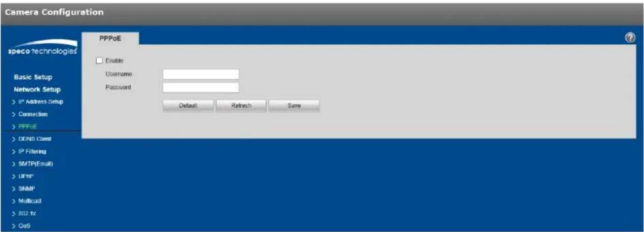
text_image
Camera Configuration speco technologies Basic Setup Network Setup > IP Address Setup > Connection > PPPoE > DONS Client > IP Filtering > SMTP(Email) > UPnP > SNMP > Multicast > 802.1x > QoS PPPoE Enable Username Password Default Retrench SaveFigure 5-20
5.2.4 DDNS Client
The DDNS interface is shown in Figure 5-21.
Enable DDNS and click "Save". If the conncon is successful, the status will indicate that it is connected.

text_image
Camera Configuration DDNS Client Enable Server Address specoddns.net Device Domain Link State Disconnected Note: The DDNS function has not been enabled Default Refresh Save speco technologies Basic Setup Network Setup > IP Address Setup > Connection > PPPoE > DDNS Client > IP Filtering > SMTP(Email) > UPnP > SNMP > Multicast > 802 tx > QoSFigure 5-21
5.2.5 IP Filtering
The IP Itering interface is shown in Figure 5-22.
This can be set up so that only specied IP or Mac addresses can access the device.
Individual IP addresses or IP segments can be used.
Aer adding the IP/Mac addresses, click on Trusted Sites to enable Itering. Click "Save" to save the sengs.

text_image
Camera Configuration speco technologies IP Filtering Trusted Sites Basic Setup Network Setup > IP Address Setup > Connection > PPPoE > DDNS Client > IP Filtering > SMTP(Email) > UPnP > SNMP > Multicast > 802.1x > QoS IP address /MAC address Modify Delete Add IP/MAC Remove All Default Refresh SaveFigure 5-22
5.2.6 SMTP (Email)
The email interface is shown in Figure 5-23.
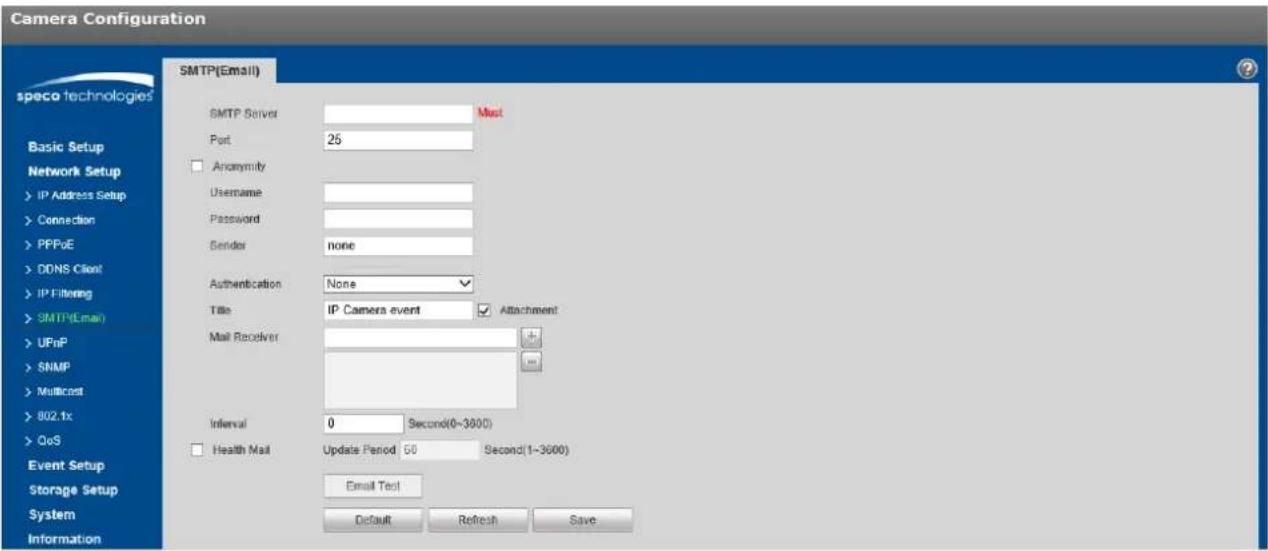
text_image
Camera Configuration speco technologies SMTP(Email) SMTP Server Port 25 Anonymity Username Password Sender none Authentication None Title IP Camera event Attachment Mail Receiver Interval 0 Second(0-3600) Health Mail Update Period 50 Second(1-3600) Email Test Default Refresh SaveFigure 5-23
Refer to the following table for more informaon.
| Parameter | Funcon |
| SMTP Server | Email server, such as smtp.gmail.com, etc. |
| Port | Default value is 25. Modify as necessary. |
| Anonymity | For email servers which support anonymous email funcon. The informaon of the sender wouldn't be displayed. |
| User Name | The user name of the sender's email account. |
| Password | The password of sender's email account. |
| Sender | Sender's email address. |
| Authencaon (Encrypon mode) | Select SSL, TLS or none. |
| Title (Subject) | Enter email subject. |
| Aachment | A snapshot of the event can be sent out as an aachment if enabled. |
| Mail receiver | Enter receiver's email address here. Maximum of three addresses can be entered. |
| Interval | The send interval range is from 0 to 3600 seconds. 0 means there is no interval. |
| Email test | The system will send out an email once to test the connecvity.Before the email test, make sure to save the email setup informaon. |
5.2.7 UPnP
UPnP can be used to allow port forwarding on a router without user intervenon. Typically, residential routers have UPnP enabled while commercial routers have it disabled by default. See Figure 5-24 for the interface.
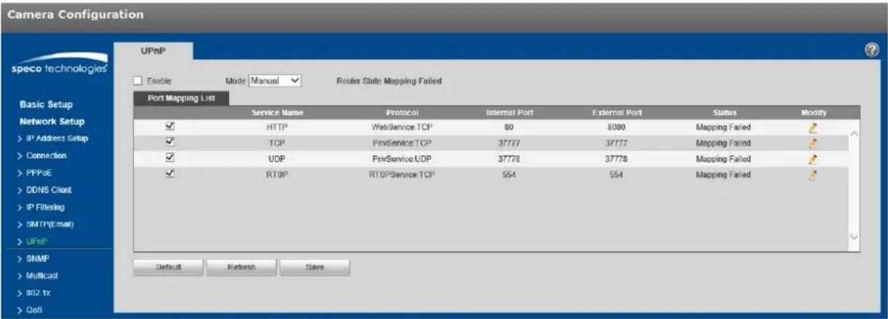
text_image
Camera Configuration UPnP speco technologies Enable Mode Manual Router State Mapping Failed Port Mapping List Service Name Protocol Internal Port External Port Status Modify ✓ HTTP WebService.TCP 80 8080 Mapping Failed ✓ TCP PrivService.TCP 37777 37777 Mapping Failed ✓ UDP PrivService.UDP 37778 37778 Mapping Failed ✓ RTSP RTSP Service TCP 554 554 Mapping Failed Default Refresh SlaveFigure 5-24
5.2.8 SNMP
The SNMP interface is shown in Figure 5-25.
Before using SNMP, make sure to install an SNMP management tool and set the parameters. Aer setup, the device must be restored to acvate the new setup.

text_image
speco technologies SNMP SNMP Version SNMP v1 SNMP v2 SNMP v3 Basic Setup Network Setup > IP Address Setup > Connection > PPPoE > DDNS Client > IP Filtering > SMTP(Email) > UPnP > SNMP > Multicast > 802.1x > QoS Event Setup Storage Setup System Information Live SNMP Port 161 (1~65535) Read Community public Write Community private Trap Address Trap Port 162 Read-only Username public Authentication Type MD5 SHA Authentication Password Encryption Type CBC-DES Encryption Password Read&write private Username Authentication Type MD5 SHA Authentication Password Encryption Type CBC-DES Encryption Password Default Refresh SaveFigure 5-25
Refer to the following table for more informaon. The parameters in the rst table apply to all versions - v1, v2, and v3.
| Parameter | Funcon |
| SNMP Version | Check the version to be used. If v3 is checked, the other version cannot be checked unl v3 is unchecked. |
| SNMP port | The value ranges from 1 to 65535. The default port is UDP port 161. |
| Read community | Read-only access to all SNMP targets, default is public.Note: Only number, leer, _, and – are supported. |
| Write community | Read/write access to all SNMP targets, default is private.Note: Only number, leer, _, and – are supported. |
| Trap address | The desnaon address of the Trap informaon from the proxy program of the device. |
| Trap Address | Address for where to send Trap message. |
| Trap Port | Port which sends Trap message, default is 162, range 1~65535. |
The parameters below are available when SNMP v3 is enabled.
| Parameter | Funcon |
| SNMP Version | SNMP v3 |
| Read-onlyUsername | Default is public.Note:Name can consist of numbers, leers and underline. |
| Read/WriteUsername | Default is private.Note:Name only can be number, leer and underline. |
| Authencaon | Select MD5 or SHA, default is MD5. |
| AuthencaonPassword | Password must be not less than 8 characters. |
| Encrypon | CBC-DES |
| EncryponPassword | Password must be not less than 8 characters. |
5.2.9 Mulcast
The mulcast interface is shown in Figure 5-26.
Mulcast is a transmission mode of data packets. When there are mulple desnaons that will receive the same video stream, multicast can be used to reduce bandwidth and CPU load on the device. To set up mulcast, make sure that network switches/routers that are being used have mulcast support.

text_image
Camera Configuration speco technologies Basic Setup Network Setup > IP Address Setup > Connection > PPPoE > DDNS Client > IP Filtering > SMTP(Email) > UPnP > SNMP > Multicast > 802.1x > QoS Multicast Main Stream Enable Multicast Address 224 1 0 0 (224.0.0-239.255.265.265) Port 40000 (1025-65534) Sub Stream Enable Sub Stream 1 Multicast Address 224 1 2 4 (224.0.0-239.255.265.265) Port 40016 (1025-65534) Default Refresh SaveFigure 5-26
Refer to the following table for more informaon.
| Parameter | Funcon |
| Enable | Select to enable mulcast funcon. Main stream and sub stream cannot be used at the same me. |
| Mulcast address | Main/sub stream mulcast default address is 224.1.2.4 and its range is 224.0.0.0~239.255.255.255. |
| Port | Mulcast port. Main stream is 40000, sub stream1 is 40016, sub stream2 is 40032 and the range is 1025~65534. |
5.2.10 802.1x
802.1x (port based network access control protocol) provides an authencaon method for a device to connect to a LAN.
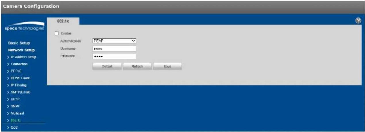
text_image
Camera Configuration speco technologies 802.1x Enable Authentication PEAP Username none Password ***** Default Retreach Save Basic Setup Network Setup > IP Address Setup > Connection > PPPoE > DDNS Client > IP Filtering > SMTP(Email) > UPnP > SNMP > Multicast > 802.1x > QoSFigure 5-27
Refer to the following table for more informaon.
| Parameter | Funcon |
| Authencaon | PEAP (protected EAP protocol). |
| Username | Enter the user name, which is authenticated by the server. |
| Password | Enter the password. |
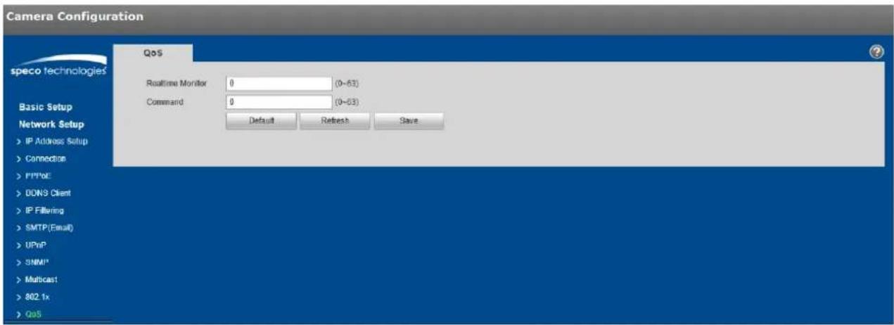
5.2.11 QoS
The QoS (quality of service) interface is shown below. See Figure 5-28.
QoS can be set for stream viewing and control for the IP camera. Specific DSCP values (in decimal format) can be set for each, with the values ranging from 0 to 63.
text_image
Camera Configuration speco technologies QoS Realtime Monitor 0 (0-63) Command 0 (0-03) Default Refresh Save Basic Setup Network Setup > IP Address Setup > Connection > PPPoE > DON'S Client > IP Filtering > SMTP (Email) > UPnP > SNMP* > Multicast > 802.1x > QoSFigure 5-28
5.2.12 HTTPS
For devices that have HTTPS capability, a cercate can be created or a signed cercate can be uploaded.
Step 1
Create a cercate or upload a signed cercate.
● To create a cercate, follow the direcons below.
- Select "Network Setup > HTTPS", shown in Figure 5-29.

text_image
Camera Configuration speco technologies Basic Setup Network Setup > IP Address Setup > Connection > PPPoE > DDNS Client > IP Filtering > SMTP(Email) > UPnP > SNMP > Multicast > 802 tx > QoS > HTTPS Event Setup Storage Setup System HTTPS Enable HTTPS Create Certificate Create Request Created Request Created Delete Install Download Install Signed Certificate Certificate Path Browse... Certificate Key Path Browse Upload Certificate Installed Certificate Installed Delete Attribute Refresh SaveFigure 5-29
- Click "Create" and a dialog box will pop up, which is shown in Figure 5-30.
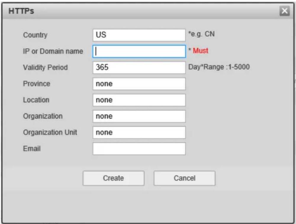
text_image
HTTPS Country US *e.g. CN IP or Domain name | * Must Validity Period 365 Day*Range :1-5000 Province None Location None Organization None Organization Unit None Email Create CancelFigure 5-30
- Fill in all elds and click "Create". A message will pop up stating that the cercate has been created successfully. Make sure that the IP address or the domain name is the same as that of the device.
- Click "Install" and the cercate will be installed on the device.
- Click "Download" and save the le on the PC.
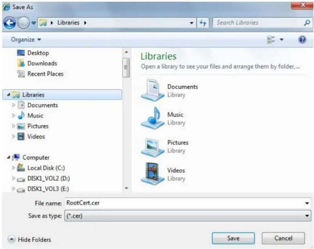
text_image
Save As Libraries Search Libraries Organize Desktop Downloads Recent Places Libraries Documents Music Pictures Videos Computer Local Disk (C:) DISK1_VOL2 (D:) DISK1_VOL3 (E:) Libraries Open a library to see your files and arrange them by folder,... Documents Library Music Library Pictures Library Videos Library File name: RootCert.cer Save as type: (*.cer) Hide Folders Save CancelFigure 5-31
- Double click on the downloaded le. The system will display the shown in Figure 5-32.

text_image
Certificate General Details Certification Path Certificate Information This CA Root certificate is not trusted. To enable trust, install this certificate in the Trusted Root Certification Authorities store. Issued to: test Issued by: test Valid from 2016/ 7/ 8 to 2020/ 7/ 7 Install Certificate... Issuer Statement Learn more about certificates OKFigure 5-32
- Click "Install Cercate" and the Cericate Import Wizard will show, shown in Figure 5-33.
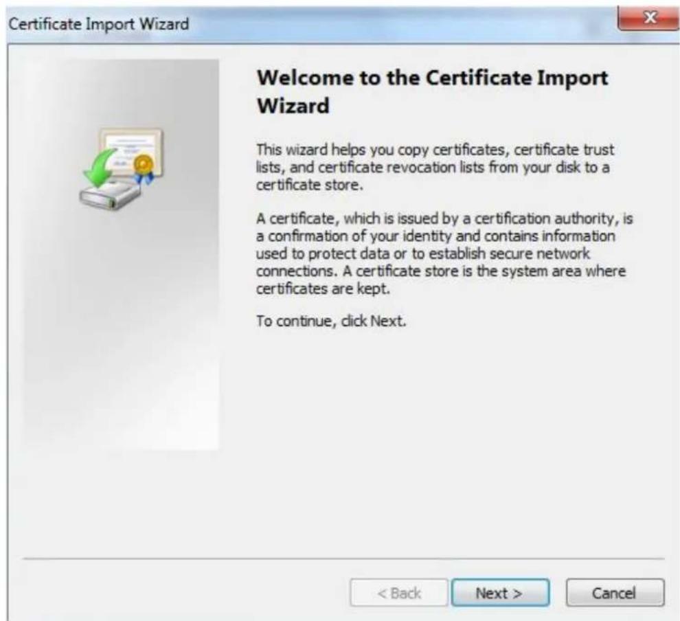
text_image
Certificate Import Wizard Welcome to the Certificate Import Wizard This wizard helps you copy certificates, certificate trust lists, and certificate revocation lists from your disk to a certificate store. A certificate, which is issued by a certification authority, is a confirmation of your identity and contains information used to protect data or to establish secure network connections. A certificate store is the system area where certificates are kept. To continue, click Next.Figure 5-33
- Click "Next" and select "Place all cercates in the following store". Click on Browse and select "Trusted Root Cercaon Authorities".

text_image
Certificate Import Wizard Certificate Store Certificate stores are system areas where certificates are kept. Windows can automatically select a certificate store, or you can specify a location for the certificate. ○ Automatically select the certificate store based on the type of certificate ● Place all certificates in the following store Certificate store: Trusted Root Certification Authorities Browse... Learn more about certificate stores < Back Next > CancelFigure 5-34
- Click "Next" and "Compleng the Cercate Import Wizard" will show, which is shown in Figure 5-35.
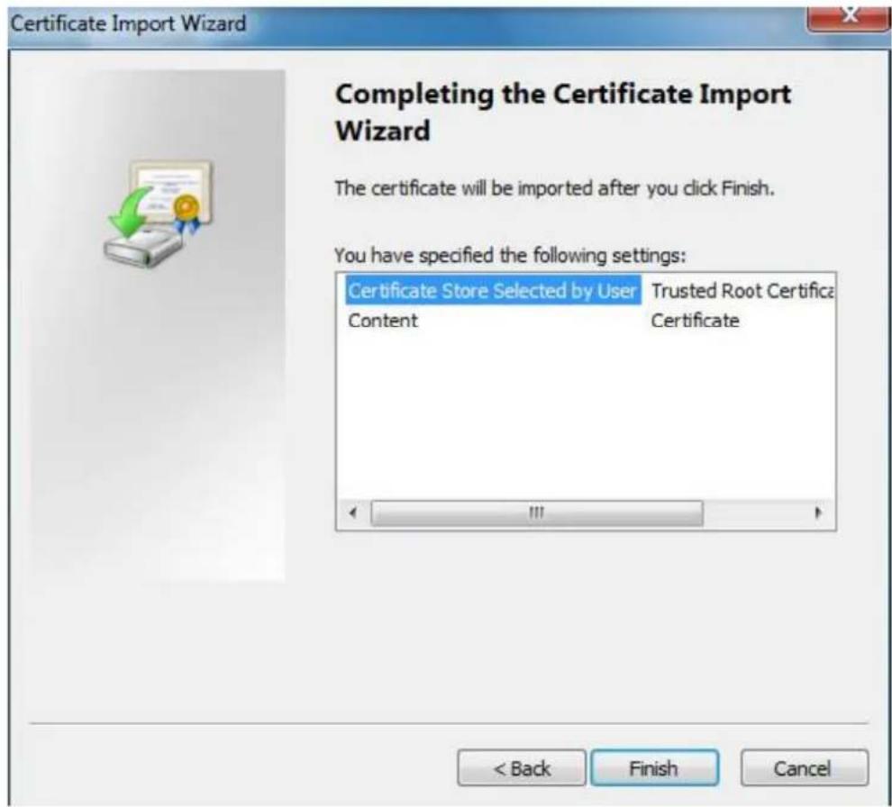
text_image
Certificate Import Wizard Completing the Certificate Import Wizard The certificate will be imported after you click Finish. You have specified the following settings: Certificate Store Selected by User Trusted Root Certifica Content Certificate < Back Finish CancelFigure 5-35
- Click "Finish", and "Security Warning" dialog box will show, which is shown in Figure 5-36.

text_image
Security Warning You are about to install a certificate from a certification authority (CA) claiming to represent: test Windows cannot validate that the certificate is actually from "test". You should confirm its origin by contacting "test". The following number will assist you in this process: Thumbprint (sha1): 6D811FD2 E82313A8 663514ED 2CA36E6B 7D425FA6 Warning: If you install this root certificate, Windows will automatically trust any certificate issued by this CA. Installing a certificate with an unconfirmed thumbprint is a security risk. If you click "Yes" you acknowledge this risk. Do you want to install this certificate? Yes NoFigure 5-36
- Click "Yes" and a dialog box will pop up showing that the import was successful. Click "Ok" to complete downloading the cercate.

text_image
Certificate Import Wizard The import was successful. OKFigure 5-37
● To use the "Install Signed Cercate" option, follow the direcons below.
- In the HTTPS interface, select the cercate path and the cercate key path and click Upload.
- Install the root cercate - refer to steps 6\~11 for details.
- Check "Enable HTTPS" and click "Save". The device will reboot.
- Use HTTPS to log in by entering the IP address in the browser, starng with hps://. The browser will show a cercate error if the cercate is not installed, which is shown in Figure 5-38.
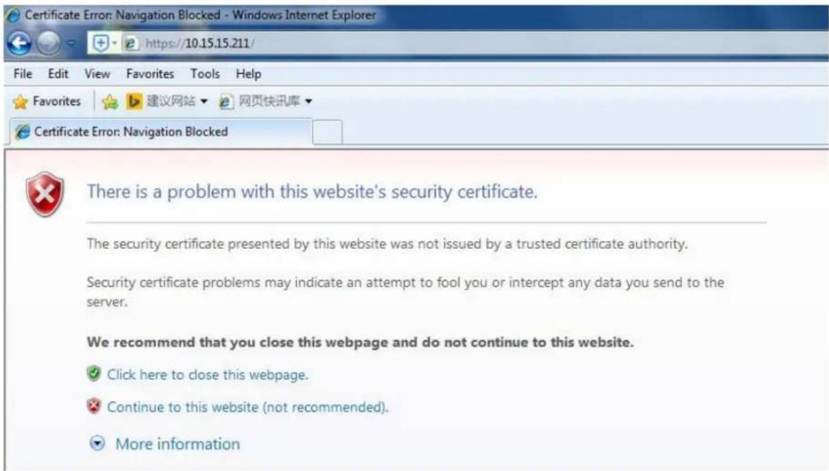
text_image
Certificate Error: Navigation Blocked - Windows Internet Explorer https://10.15.15.211/ File Edit View Favorites Tools Help Favorites 建议网站 网页快讯库 Certificate Error: Navigation Blocked There is a problem with this website's security certificate. The security certificate presented by this website was not issued by a trusted certificate authority. Security certificate problems may indicate an attempt to fool you or intercept any data you send to the server. We recommend that you close this webpage and do not continue to this website. ✓ Click here to close this webpage. ✗ Continue to this website (not recommended). ▼ More informationFigure 5-38
5.3 Event Setup
5.3.1 Video detecon
5.3.1.1 Moon Detecon
Step 1
Select "Event Setup > Video Detecon > Moon Detecon" to display the moon detecon interface shown in Figure 5-39.

text_image
Camera Configuration Motion Detection Tampering Scene Changing speco technologies Basic Setup Network Setup Event Setup > Motion Detection > Audio Detection > Smart Plan > Analytics > Face Detection > Alarm > Abnormality Storage Setup System Information Live Enable Waiting Period Setup Anti-Dither 0 Second (0-100) Area Setup Record Record Delay 10 Second (10-300) Relay-out Alarm Delay 10 Second (10-300) Sond Email Snapshot Default Refresh SaveFigure 5-39
Step 2
Select "Enable" to enable moon detecon.
Step 3
Set up moon detecon zone.
- Click "Setup" for Area to show the interface in Figure 5-40.

text_image
Area Region Name Region1 Sensitivity 10 Threshold 15 Remove All Delete (Or Rightclick) Save CancelFigure 5-40
- Up to 4 dierent zones can be set, with a dierent set of dened areas, sensitivities, and threshold values. The name eld is the nickname for the corresponding zone.
- Higher sensitivity value means that it is easier to trigger a moon event. The threshold value represents how much of the overall moon detecon zone needs to have moon in order for the moon event to trigger. The enre video image is the dened as the moon zone by default.
- Click "Save" to save the sengs.
Step 4
Refer to the table below for more details on the parameters.
| Parameter | Funcon |
| Working Period | Set up the schedule for when moon alarms will get generated by the device.Note: In cases where the IP camera is recording to an NVR, if there is a period of me where moon alarm is disabled in the camera, then even if moon recording is enabled on the NVR, the camera will not send any moon alarms to the NVR during that me period. |
| An-dither | The device only generates one alarm during the an-dither period. The value ranges from 0s to 100s. |
| Area | Moon zone setup, as described in this secon. |
| Record | If enabled, when a moon alarm occurs, the device will record to the desnaon that's set under the Storage Setup > Desnaon secon. |
| Record Delay | System can delay the record for specied me aer alarm ended. The value ranges from 10s to 300s. |
| Relay out | Enable it for a relay out to an alarm device. This applies to only models with a relay output conncon. |
| Alarm Delay | System can delay the alarm output for a specied me aer the alarm ends. |
| Send Email | If enabled, the device can send out an email when a moon alarm occurs.An email address must rst be set up in Network Setup. |
| Snapshot | Enable to generate a snapshot when a moon alarm occurs. The snapshot schedul can be set up in Storage>Schedule. |
Step 5
Click "Save" to save the sengs.
5.3.1.2 Tampering
Step 1
Go to the Tampering tab to display the interface of "Video Tampering" which is shown in Figure 5-41.

text_image
Camera Configuration Motion Detection Tampering Scene Changing speco technologies Enable Video Tampering Enable Detocus Detection Working Period Setup Record Record Delay 10 Second (10-300) Relay-out Alarm Delay 10 Second (10-300) Send Email Snapshot Default Refresh Save LiveFigure 5-41
Step 2
Set up the parameters. The parameters for alarm acons are the same as moon detecon.
Step 3
Click "Save" to save the sengs.
5.3.1.3 Scene Changing
Step 1
Go to the Scene Changing tab to display the interface of "Scene Changing". Scene Changing will generate an alarm when the scene in the video image changes drascally.
Step 2
Check "Enable" to enable the funcon of scene changing.
Step 3
Set up the parameters. The parameters for alarm acons are the same as moon detecon.
Step 4
Click "Save" to complete the setup of scene changing.
5.3.2 Audio Detecon
Step 1
Select "Event Setup > Audio Detecon" to display the interface of "Audio Detection" which is shown in Figure 5-42.
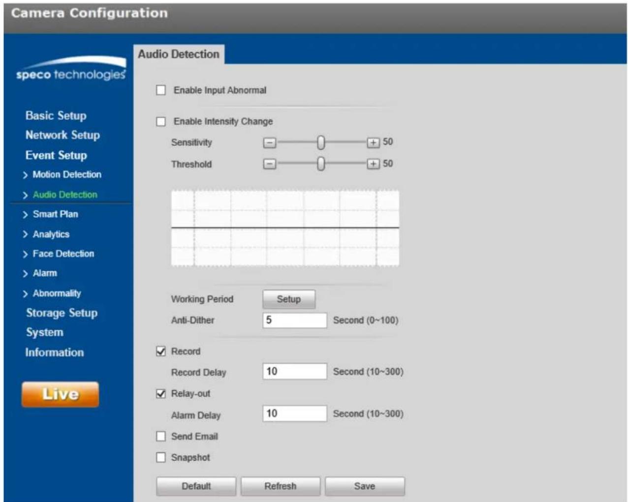
text_image
Camera Configuration speco technologies Basic Setup Network Setup Event Setup > Motion Detection > Audio Detection > Smart Plan > Analytics > Face Detection > Alarm > Abnormality Storage Setup System Information Live Audio Detection Enable Input Abnormal Enable Intensity Change Sensitivity - + 50 Threshold - + 50 Working Period Setup Anti-Dither 5 Second (0~100) ✓ Record Record Delay 10 Second (10~300) ✓ Relay-out Alarm Delay 10 Second (10~300) □ Send Email □ Snapshot Default Refresh SaveFigure 5-42
Step 2
Refer to the table below for more details on the parameters.
| Parameter | Funcon |
| Enable input abnormal | If enabled, an alarm will be triggered when there is abnormal audio being detected. |
| Enable intensity change | If enabled, an alarm will be triggered if the volume intensity of the audio exceeds the threshold. |
| Sensitivity | Sensitivity for abnormal audio volume. |
| Threshold | Threshold for volume intensity. |
| Working Period | Set up the schedule for when alarms will get generated by the device. |
| An-dither | The device only generates one alarm during the an-dither period. The value ranges from 0s to 100s. |
| Record | If enabled, when an alarm occurs, the device will record to the desnaon that's set under the Storage Setup > Desnaon secon. |
| Record Delay | System can delay the record for specied me aer alarm ended. The value ranges from 10s to 300s. |
| Relay out | Enable it for a relay out to an alarm device. This applies to only models with a relay output conncon. |
| Alarm Delay | System can delay the alarm output for a specied me aer the alarm ends. |
| Send Email | If enabled, the device can send out an email when an alarm occurs.An email address must rst be set up in Network Setup. |
| Snapshot | Enable to generate a snapshot when an alarm occurs. The snapshot schedule can be set up in Storage>Schedule. |
Step 3
Click "Save" to save the sengs.
5.3.3 Smart Plan (if equipped)
Specific models may have dierent types of intelligent video funcons. Only one type of analyc funcon can be utilized at a time, which can be enabled in Smart plan.
Step 1
Select "Event Setup > Smart Plan", as shown in Figure 5-43.

text_image
Camera Configuration speco technologies Smart Plan Basic Setup Network Setup Event Setup >Motion Detection >Audio Detection >Smart Plan >Analytics >Face Detection >Alarm >Abnormality Storage Setup System Information Live Refresh SaveFigure 5-43
Step 2
Click "Save" to save the sengs.
5.3.4 Intelligent Video
Basic requirements of scene selecon to take into consideraon:
● The total size of the target should not be larger than 10% of the image.
● The target size in the image should be larger than 15x15.
- The dience of the brightness value between the target and the background should not be less than 10 gray levels.
- Target should appear in the image at least 2 seconds connuously. The movement distance has to be bigger than the width of the target itself and no less than 15 pixels.
- It is recommended to not use analycs in areas where lightng changes frequently and surfaces are reecve.
5.3.4.1 Analycs
5.3.4.1.1 Tripwire
An alarm will be triggered when the target crosses the line according to the movement direcon that has been set.
There needs to be some me from when the target appears to when the target is conrmed, so there should be some space on both sides of the line.
Step 1
Select "Event Setup > Analycs".
Step 2
Click “+” to set the rule name and select the rule type as “Tripwire” as shown in Figure 5-44.
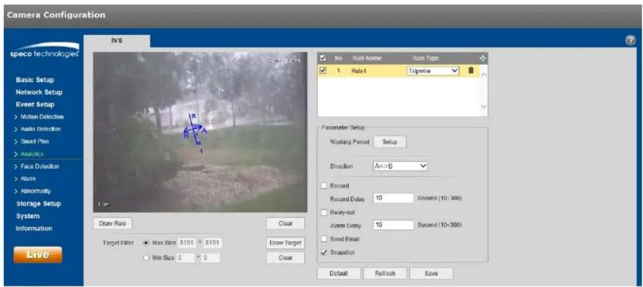
text_image
Camera Configuration speco technologies Basic Setup Network Setup Event Setup Motion Detection Audio Detection Smart Plan Analytics Face Detection Alarm Abnormality Storage Setup System Information Live IVS Draw Rate Clear Target Filter Max Size 8191 * 8191 Min Size 0 * 0 Draw Target Clear No Rule Name Rule Type 1 Rule1 Tripwire Parameter Setup Working Period Setup Direction A<>B Record Record Delay 10 Second (10-300) Relay-out Alarm Delay 10 Second (10-300) Send Email Snapshot Default Refresh SaveFigure 5-44
Step 3
Click "Draw Rule" to draw a line in the scene. Click the right mouse buon to complete the seng.
Step 4
Click "Draw Target" to set the size of the target in the image.
Step 5
Refer to the following table for more details on the parameters.
| Parameter | Funcon |
| Working Period | Set up the schedule for when alarms will get generated by the device. |
| Direcon | Sets the direction of tripwire. Options are: A->B, B->A, or A<->B. |
| Record | If enabled, when an alarm occurs, the device will record to the desnaon that's set under the Storage Setup > Desnaon secon. |
| Record Delay | System can delay the record for specied me aer alarm ended. The value ranges from 10s to 300s. |
| Relay out | Enable it for a relay out to an alarm device. This applies to only models with a relay output conncon. |
| Alarm Delay | System can delay the alarm output for a specied me aer the alarm ends. |
| Send Email | If enabled, the device can send out an email when an alarm occurs.An email address must rst be set up in Network Setup. |
| Snapshot | Enable to generate a snapshot when an alarm occurs. The snapshot schedule can be set up in Storage>Schedule. |
Step 5
Click "Save" to save the sengs.
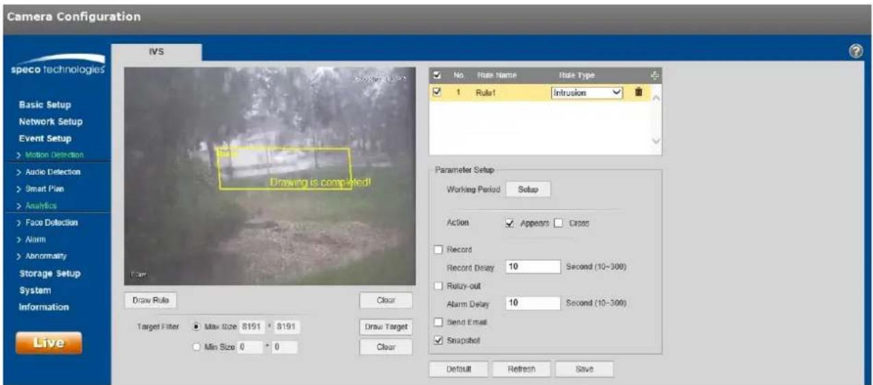
5.3.4.2 Intrusion
Intrusion includes these acons: cross and appears.
● Cross means that an alarm will be triggered when the target enters or exits the area.
● Appears means that an alarm will be triggered when the target appears in the area.
Step 1
In the IVS tab, click “+” to set rule name and select the rule type as “Intrusion” as shown in Figure 5-45.
text_image
Camera Configuration IWS speco technologies Basic Setup Network Setup Event Setup > Motion Detection > Audio Detection > Smart Plan > Analytics > Face Detection > Alarm > Abnormality Storage Setup System Information Live Draw Rule Clear Target Filter ● Max Size: 8151 • 8191 ○ Min Size: 0 • 0 Drawing is completed! Draw Target Clear No Rule Name Rule Type ✓ Rule1 Infrusion Parameter Setup Working Period Setup Action ✓ Appears ☐ Cross Record Record Delay 10 Second (10-300) Relay-out Alarm Delay 10 Second (10-300) Send Email ✓ Snapshot Default Refresh SaveFigure 5-45
Step 2
Click "Draw Rule" to draw an area in the image.
Step 3
Click "Draw Target" to set the size of the target in the image.
Step 4
Refer to the following table for more details on the parameters.
| Parameter | Funcon |
| Working Period | Set up the schedule for when alarms will get generated by the device. |
| Acon | Select Appears or Cross. |
| Record | If enabled, when an alarm occurs, the device will record to the desnaon that's set under the Storage Setup > Desnaon secon. |
| Record Delay | System can delay the record for specied me aer alarm ended. The value ranges from 10s to 300s. |
| Relay out | Enable it for a relay out to an alarm device. This applies to only models with a relay output conncon. |
| Alarm Delay | System can delay the alarm output for a specied me aer the alarm ends. |
| Send Email | If enabled, the device can send out an email when an alarm occurs.An email address must rst be set up in Network Setup. |
| Snapshot | Enable to generate a snapshot when an alarm occurs. The snapshot schedule can be set up in Storage>Schedule. |
Step 5
Click "Save" to save the sengs.
5.3.4.3 Abandoned Object
Abandoned object means that an alarm will be triggered if an object has been le in the scene for longer than the me limit that has been set.
To avoid false alarms caused by people or vehicles, the size of the object generally should be smaller than people or vehicles.
Step 1
In the IVS tab, click “+” to set the rule name and select the rule type as “Abandoned Object” as shown in
Figure 5-46.

text_image
Camera Configuration IVS speco technologies Basic Setup Network Setup Event Setup >Motion Detection >Audio Detection >Smart Plan >Analytics >Face Detection >Alarm >Abnormality Storage Setup System Information Live Drawing is completed! Draw Rule Clear Target Filter ● Max Size 8191 * 8191 ○ Min Size 0 * 0 Draw Target Clear No Rule Name Rule Type 1 Rule1 Abandoned Ot Parameter Setup Working Period Setup Keep Time 10 Second (6-3600) Record Record Delay 10 Second (10-300) Reentry-out Alarm Delay 10 Second (10-300) Sound Email Snapshot Default Refresh SaveFigure 5-46
Step 2
Click "Draw Rule" to draw an area in the image.
Step 3
Click "Draw Target" to set the size of the target in the image.
Step 4
Refer to the following table for more details on the parameters.
| Parameter | Funcon |
| Working Period | Set up the schedule for when alarms will get generated by the device. |
| Keep me | Time limit before alarm is triggered. |
| Record | If enabled, when an alarm occurs, the device will record to the desnaon that's set under the Storage Setup > Desnaon secon. |
| Record Delay | System can delay the record for specied me aer alarm ended. The value ranges from 10s to 300s. |
| Relay out | Enable it for a relay out to an alarm device. This applies to only models with a relay output conncon. |
| Alarm Delay | System can delay the alarm output for a specied me aer the alarm ends. |
| Send Email | If enabled, the device can send out an email when an alarm occurs.An email address must rst be set up in Network Setup. |
| Snapshot | Enable to generate a snapshot when an alarm occurs. The snapshot schedule can be set up in Storage>Schedule. |
Step 5
Click "Save" to save the sengs.
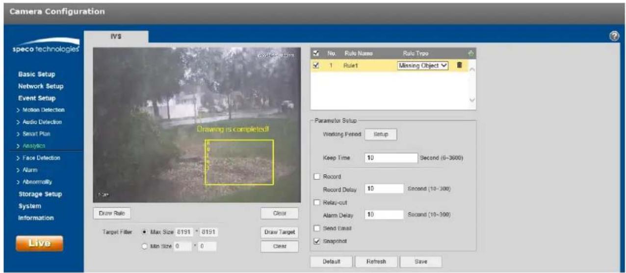
5.3.4.4 Missing Object
Missing object means that an alarm will be triggered if an object has been removed from the scene for longer than the me limit that has been set.
Step 1
In the IVS tab, click “+” to set the rule name and select the rule type as “Missing Object”, as shown in Figure 5-47.
text_image
Camera Configuration speco technologies Basic Setup Network Setup Event Setup >Motion Detection >Audio Detection >Smart Plan >Analytics >Face Detection >Alarm >Abnormally Storage Setup System Information Live IVS Drawing is completed! Draw Rule Clear Target Filter ● Max Size 0191 * 0191 ○ Min Size 0 * 0 Draw Target Clear No. Rule Name Rule Type ✓ 1 Rule1 Missing Object ✓ Parameter Setup Working Period Setup Keep Time 10 Second (6-3600) Record Record Delay 10 Second (10-300) Relay-out Alarm Delay 10 Second (10-300) Send Email ✓ Snapshot Default Refresh SaveFigure 5-47
Step 2
Click "Draw Rule" to draw an area in the image.
Step 3
Click "Draw Target" to set the size of the target in the image.
Step 4
Refer to the following table for more details on the parameters.
| Parameter | Funcon |
| Working Period | Set up the schedule for when alarms will get generated by the device. |
| Keep me | Time limit before alarm is triggered. |
| Record | If enabled, when an alarm occurs, the device will record to the desnaon that's set under the Storage Setup > Desnaon secon. |
| Record Delay | System can delay the record for specied me aer alarm ended. The value ranges from 10s to 300s. |
| Relay out | Enable it for a relay out to an alarm device. This applies to only models with a relay output conncon. |
| Alarm Delay | System can delay the alarm output for a specied me aer the alarm ends. |
| Send Email | If enabled, the device can send out an email when an alarm occurs.An email address must rst be set up in Network Setup. |
| Snapshot | Enable to generate a snapshot when an alarm occurs. The snapshot schedule can be set up in Storage>Schedule. |
Step 5
Click "Save" to save the sengs.
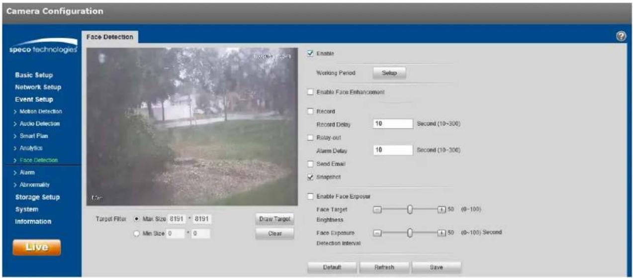
5.3.5 Face Detecon
Step 1
Select "Event Setup > Face Detecon" to display the "Face Detection" interface, shown in Figure 5-48.
text_image
Camera Configuration Face Detection speco technologies Basic Setup Network Setup Event Setup >Motion Detection >Audio Detection >Smart Plan >Analytics >Face Detection >Alarm >Abnormality Storage Setup System Information Live Target Filter ● Max Size 8191 • 8191 ○ Min Size 0 = 0 Draw Target Clear Enable Working Period Setup Enable Face Enhancement Record Record Delay 10 Second (10-300) Relay-out Alarm Delay 10 Second (10-300) Send Email Snapshot Enable Face Exposure Face Target 50 (0-100) Brightness Face Exposure 50 (0-100) Second Detection Interval Default Refresh SaveFigure 5-48
Step 2
Select "Enable" to enable the face detecon funcon.
Step 3
Click "Draw Target" to set the size of the target in the image.
Step 4
Refer to the following table for more details on the parameters.
| Parameter | Funcon |
| Working Period | Set up the schedule for when alarms will get generated by the device. |
| Enable Face Enhancement | Select “Enable Face Enhancement” to enhance the face image when the stream quality is very low. |
| Record | If enabled, when an alarm occurs, the device will record to the desnaon that's set under the Storage Setup > Desnaon secon. |
| Record Delay | System can delay the record for specied me aer alarm ended. The value ranges from 10s to 300s. |
| Relay out | Enable it for a relay out to an alarm device. This applies to only models with a relay output conncon. |
| Alarm Delay | System can delay the alarm output for a specied me aer the alarm ends. |
| Send Email | If enabled, the device can send out an email when an alarm occurs.An email address must rst be set up in Network Setup. |
| Snapshot | Enable to generate a snapshot when an alarm occurs. The snapshot schedule can be set up in Storage>Schedule. |
Step 5
Click "Save" to save the sengs.
5.3.6 Heat Map
5.3.6.1 Heat Map
Heat map is the set of heat stascs of a moving object, for which a report can be generated. The color range is from blue to red, where blue means the minimum heat value and red means the maximum heat value.
When heat map is used, mirroring, view angle changes and heat map's original data will be cleared.
Step 1
Select "Event Setup > Heat Map > Heat Map" and to display the "Heat Map" interface, shown in Figure 5-49.

text_image
Camera Configuration Hot Map Report speco technologies Basic Setup Network Setup Event Setup >Motion Detection >Audio Detection >Smart Plan >Analytics >Heat Map >Narm >Abnormality Storage Setup System Information Live Enable Working Period Setup Default Refresh SaveFigure 5-49
Step 2
Select "Enable" to enable the heat map funcon.
Step 3
Set the schedule, in the same way as moon schedule setup.
Step 4
Click "Save" to save the sengs.
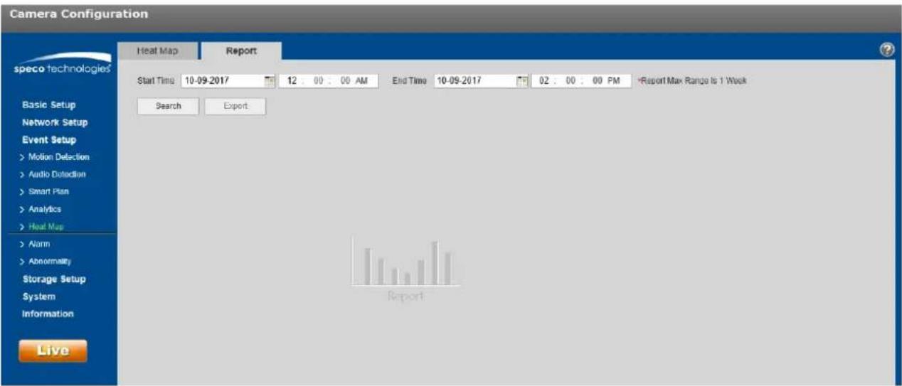
5.3.6.2 Report
Step 1
Select the Report tab, as shown in Figure 5-50.
text_image
Camera Configuration Heat Map Report speco technologies Start Time 10-09-2017 12:00:00 AM End Time 10-09-2017 02:00:00 PM -Report Max Range Is 1 Week Search Export Basic Setup Network Setup Event Setup >Motion Detection >Audio Detection >Smart Plan >Analytics >Heat Maps >Airm >Abnormality Storage Setup System Information LiveFigure 5-50
Step 2
Set the begin me and the end me for the report.
Step 3
Click "Search" to generate the stascs and then click "Export" to export the report.
5.3.7 Alarm

text_image
Camera Configuration speco technologies Basic Setup Network Setup Event Setup >Motion Detection >Audio Detection >Smart Plan >Analytics >Face Detection >Alarm >Abnormality Storage Setup System Information Live Alarm Enable Relay-in Alarm1 Working Period Setup Anti Dilther 0 Second (0-100) Sensor Type NO Record Record Delay 10 Second (10-300) Relay-out Alarm Delay 10 Second (10-300) Send Email Snapshot Default Refresh SaveFigure 5-51
| Parameter | Funcon |
| Enable | Check to enable relay output. |
| Relay-in | The default is alarm 1. Some models may have alarm 2. |
| Sensor Type | Select between normally open (NO) and normally closed (NC). |
5.3.8 Abnormality
Abnormality includes: No SD Card, Capacity Warning, SD Card Error, Disconnecon, IP Conict and Unauthorized Access.
Note:
Models with an SD card slot have these funcons: No SD card, capacity warning, and SD card error.
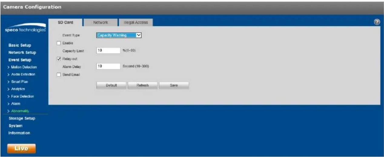
text_image
Camera Configuration speco technologies SD Card Network Illegal Access Event Type Capacity Warning Enable Capacity Limit 10 %(0-90) Relay-out Alarm Delay 10 Second (10-300) Send Email Default Refresh Save Basic Setup Network Setup Event Setup >Motion Deflection >Audio Detection >Smart Plan >Analytics >Face Detection >Alarm >Abnormality Storage Setup System Information LiveFigure 5-52
Please refer to the following sheet for detailed informaon.
| Parameter | Funcon |
| Enable | Check to enable alarm when SD card is abnormal. |
| Relay out | Enable it for a relay out to an alarm device. This applies to only models with a relay output conneccon. |
| Alarm Delay | System can delay the alarm output for a specied me aer the alarm ends. |
| Send email | If enabled, the device can send out an email when an alarm occurs.An email address must rst be set up in Network Setup. |
| SD Card Capacity Limit | An alarm can be generated when the free space of the SD card is less than the capacity set here. |
For oine device or IP conict, the scenario is similar to SD card alarm. See Figure 5-53.
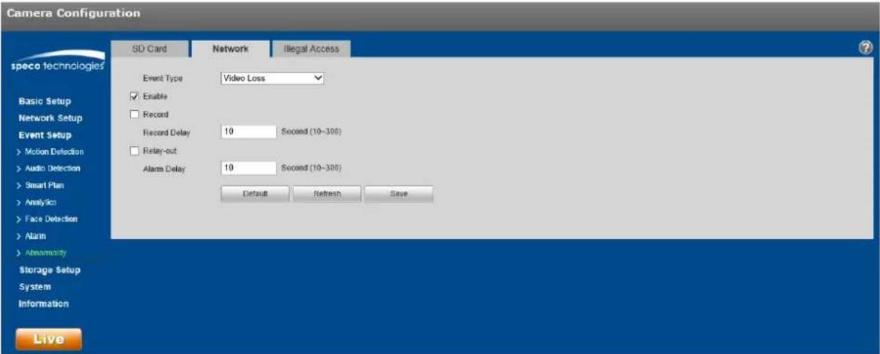
text_image
Camera Configuration speco technologies SD Card Network Illegal Access Event Type Video Loss Enable Record Record Delay 10 Second (10-300) Relay-out Alarm Delay 10 Second (10-300) Default Refresh Save Basic Setup Network Setup Event Setup > Motion Detection > Audio Detection > Smart Plan > Analytics > Face Detection > Alarm > Abnormality Storage Setup System Information LiveFigure 5-53
For illegal access, when the credenals are entered illegally, an alarm will be generated each me, up to the number of the mes that has been set. When the limit is exceeded, the user account will be locked for 30 minutes.

text_image
Camera Configuration speco technologies SD Card Network Illegal Access Enable Login Error 5 Time (3-10) Relay-out Alarm Delay 10 Second (10-300) Send Email Default Refresh Save Basic Setup Network Setup Event Setup >Motion Detection >Audio Detection >Smart Plan >Analytics >Face Detection >Alarm >Abnormality Storage Setup System Information LiveFigure 5-54
5.4 Storage Management
5.4.1 Schedule
Note:
The record mode found in the Record Control secon must be set to Auto or Manual for the device to record according to the set schedule.
5.4.1.1 Record Schedule
Step 1. Click on the Record Schedule tab under "Storage Setup > Schedule", as shown in Figure 5-55.
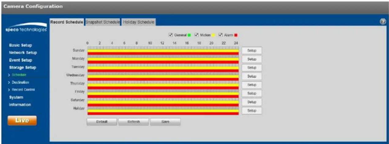
text_image
Camera Configuration Record Schedule Snapshot Schedule Holiday Schedule speco technologies Basic Setup Network Setup Event Setup Storage Setup > Schedule > Destination > Record Control System Information Live 0 2 4 6 8 10 12 14 16 18 20 22 24 Sunday Monday Tuesday Wednesday Thursday Friday Saturday Holiday General Motion Alarm Setup Setup Setup Setup Setup Setup Setup Setup Setup Setup Default Refresh Saves.Figure 5-55
Step 2. Click on Setup on the right for the day for the schedule to be set, as shown in Figure 5-56.
- Set the me periods as necessary. Up to six periods can be set for each day. The periods can be copied to each necessary day of the week.
● Three types of recording can be scheduled: General (connuous), Moon, and Alarm.
Note:
The schedule can also be set up by dragging the mouse over a me period in the Record Schedule interface (Figure 5-55).
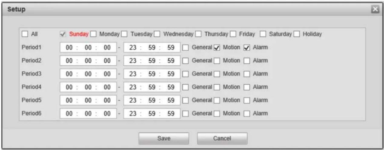
text_image
Setup All Sunday Monday Tuesday Wednesday Thursday Friday Saturday Holiday Period1 00 : 00 : 00 - 23 : 59 : 59 General Motion Alarm Period2 00 : 00 : 00 - 23 : 59 : 59 General Motion Alarm Period3 00 : 00 : 00 - 23 : 59 : 59 General Motion Alarm Period4 00 : 00 : 00 - 23 : 59 : 59 General Motion Alarm Period5 00 : 00 : 00 - 23 : 59 : 59 General Motion Alarm Period6 00 : 00 : 00 - 23 : 59 : 59 General Motion Alarm Save CancelFigure 5-56
Step 3. Click Save to return to the record schedule interface.
● Green color stands for connuous record/snapshot.
● Yellow color stands for moon detecon record/snapshot.
● Red color stands for alarm record/snapshot.
Step 4. Click Save to save the sengs.
5.4.1.2 Snapshot Schedule
The Snapshot schedule is set up in the same manner as Record Schedule. The interface is shown in Figure 5-57.

text_image
Camera Configuration Record Schedule Snapshot Schedule Holiday Schedule speco technologies Basic Setup Network Setup Event Setup Storage Setup > Schedule > Destination > Record Control System Information Live 0 2 4 6 8 10 12 14 16 18 20 22 24 Sunday Monday Tuesday Wednesday Thursday Friday Saturday Holiday General Motion Alarm Setup Setup Setup Setup Setup Setup Setup Setup Default Refresh SaveFigure 5-57
5.4.1.3 Holiday Schedule
Specific days such as holidays can be set up to have a dierent schedule.
Step 1. Click on the Holiday Schedule tab, as shown in Figure 5-58.
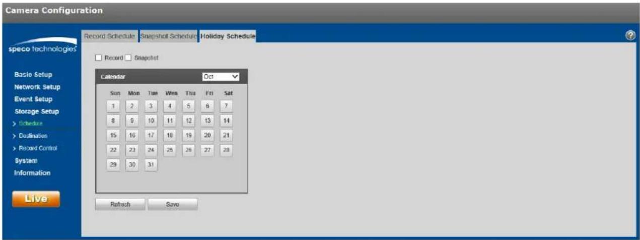
text_image
Camera Configuration Record Schedule Snapshot Schedule Holiday Schedule Record Snapshot Calendar Oct Sun Mon Tue Wed Thu Fri Sat 1 2 3 4 5 6 7 8 9 10 11 12 13 14 15 16 17 18 19 20 21 22 23 24 25 26 27 28 29 30 31 Refresh SaveFigure 5-58
Step 2. Select a date to set as a holiday. The selected date will be highlighted in yellow.
Step 3. Check Record and/or Snapshot for the desired recording mode and then click on Save.
Step 4. In the Record Schedule interface or the Snapshot Schedule interface, click on setup next to Holiday and set up the me periods accordingly.
Step 5. Click Save to save the sengs.
5.4.2 Desnaon
5.4.2.1 Path
The desnaon interface is shown in Figure 5-59.
Each of the 3 recording modes can be set up under 3 opons: Local (SD card), FTP, and NAS. This applies to both record and snapshot. Only one opon can be chosen.
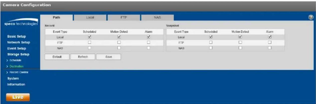
text_image
Camera Configuration Path Local FTP NAS speco technologies Record Snapshot Event Type Scheduled Motion Detect Alarm Event Type Scheduled Motion Detect Alarm Local ✓ ✓ ✓ Local ✓ ✓ ✓ FTP □ □ □ FTP □ □ □ NAS □ □ □ NAS □ □ □ Default Refresh Save Basic Setup Network Setup Event Setup Storage Setup > Schedule > Destination > Record Control System Information LiveFigure 5-59
5.4.2.2 Local
The local interface is shown in Figure 5-60.
In this interface, informaon about the Micro SD card is displayed. The card can be also formaed through this interface.
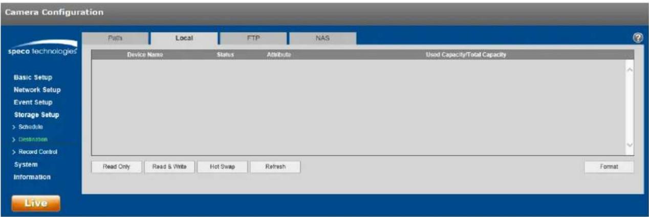
text_image
Camera Configuration Paths Local FTP NAS Device Name Status Attribute Used Capacity/Total Capacity Basic Setup Network Setup Event Setup Storage Setup > Schedule > Destination > Record Control System Information Read Only Read & Write Hot Swap Refresh Format LiveFigure 5-60
5.4.2.3 FTP
The FTP interface is shown in Figure 5-61.
Check the box to enable the FTP funcon. Enter the applicable FTP conncon informaon. Click the test buon to check if the FTP server can be contacted properly.

text_image
Camera Configuration Path Local FTP NAS speco technologies Enable Server Address 0.0.0.0 Port 21 (0-65535) User Name anonymity Password Remote Directory share Emergency (Local) Default Refresh Save LiveFigure 5-61
5.4.2.4 NAS
Check the box to enable the NAS funcon. Enter the applicable conneccon informaon. See Figure 5-62.
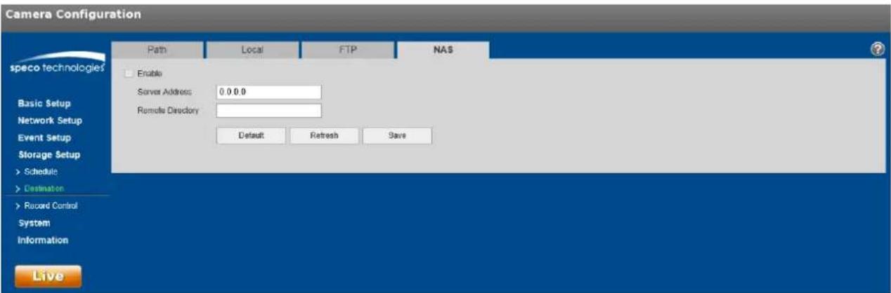
text_image
Camera Configuration Path Local FTP NAS speco technologies Enable Server Address: 0 0 0.0 Remote Directory Default Refresh Save LiveFigure 5-62
5.4.3 Record control
The record control interface is shown in Figure 5-63.
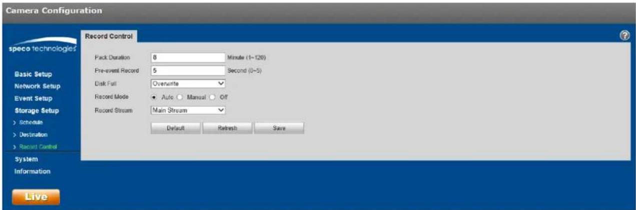
text_image
Camera Configuration Record Control Pack Duration 8 Minute (1~120) Pre-event Record 5 Second (0~5) Disk Full Overwrite Record Mode ● Auto ○ Manual ○ Off Record Stream Main Stream Default Refresh Save Live speco technologies Basic Setup Network Setup Event Setup Storage Setup > Schedule > Destination > Recent Control System InformationFigure 5-63
Refer to the following table for more informaon.
| Parameter | Funcon |
| Pack Duraon | Refers to the duraon of each le that gets saved. Default is 8 minutes. |
| Pre-record | Refers to the duraon of the recording before the actual event that gets saved. |
| Disk Full | ● Stop: Stops recording if storage is full● Overwrite: Starts to overwrite the oldest recordings if storage is full |
| Record mode | Auto / Manual / O. “O” must not be chosen for the schedule to take eect. |
| Record stream | Choose between main stream and sub stream. |
5.5 System
5.5.1 General
The General interface is shown in Figure 5-64.
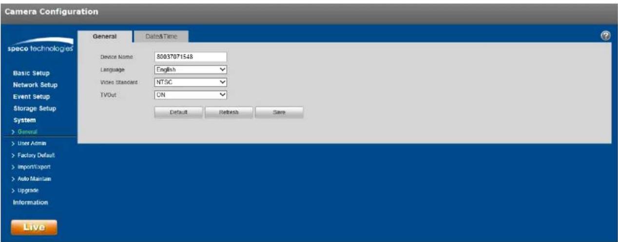
text_image
Camera Configuration General Dates&Time Device Name 80037071548 Language English Video Standard NTSC TVOut ON Default Refresh Save LiveFigure 5-64
| Parameter | Funcon |
| Device Name | Nickname for the device can be set here. By default, the serial number of the device is shown. |
| Video Standard | Displays the video standard, which is NTSC for North America. |
| TV Out | Some models will have a TV output opon. This can be turned on/o. |
The Date & Time interface is shown as in Figure 5-65.
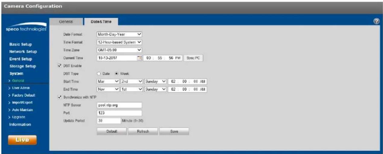
text_image
Camera Configuration speco technologies Date Format Month-Day-Year Time Format 12-Hour-based System Time Zone GMT-05.00 Current Time 10-13-2017 03 : 55 : 56 PM Sync PC ✓ DST Enable DST Type ○ Date ● Week Start Time Mar ✓ 2nd ✓ Sunday ✓ 02 : 00 : 00 AM End Time Nov ✓ 1st ✓ Sunday ✓ 02 : 00 : 00 AM ✓ Symbionize with NTP NTP Server pool.ntp.org Port 123 Update Period 30 Minute (0-30) Default Refresh Save LiveFigure 5-65
Please refer to the following sheet for detailed informaon.
| Parameter | Funcon |
| Date format | Select the display format of the date from the dropdown list. |
| Time Format | Select between a 24-hour display and a 12-hour display. |
| Time zone | Set the me zone of the device. |
| Current Time | Current me of the device. This can be set manually. |
| Sync PC | Click this buon to save the device me as the PC me. |
| DST Enable | If the locaon ulizes Daylight Saving Time (DST), check the Enable box and set up the start and end mes for DST. |
| Synchronize with NTP | Check the box to enable NTP. |
| NTP server | Set the me server address. |
| Port | Set the me server port. |
| Update period | How oen the device should synchronize the me with the me server. |
5.5.2 User Admin
- For user names and user groups, the maximum character length is 31 characters, which can be made up of numbers, leers, underline, hyphen, dot, and @.
- Password can be 0\~32 characters in numbers and leers only.
● A specific user can belong to only one group.
5.5.2.1 User Name
See Figure 5-66 for the User Name interface.
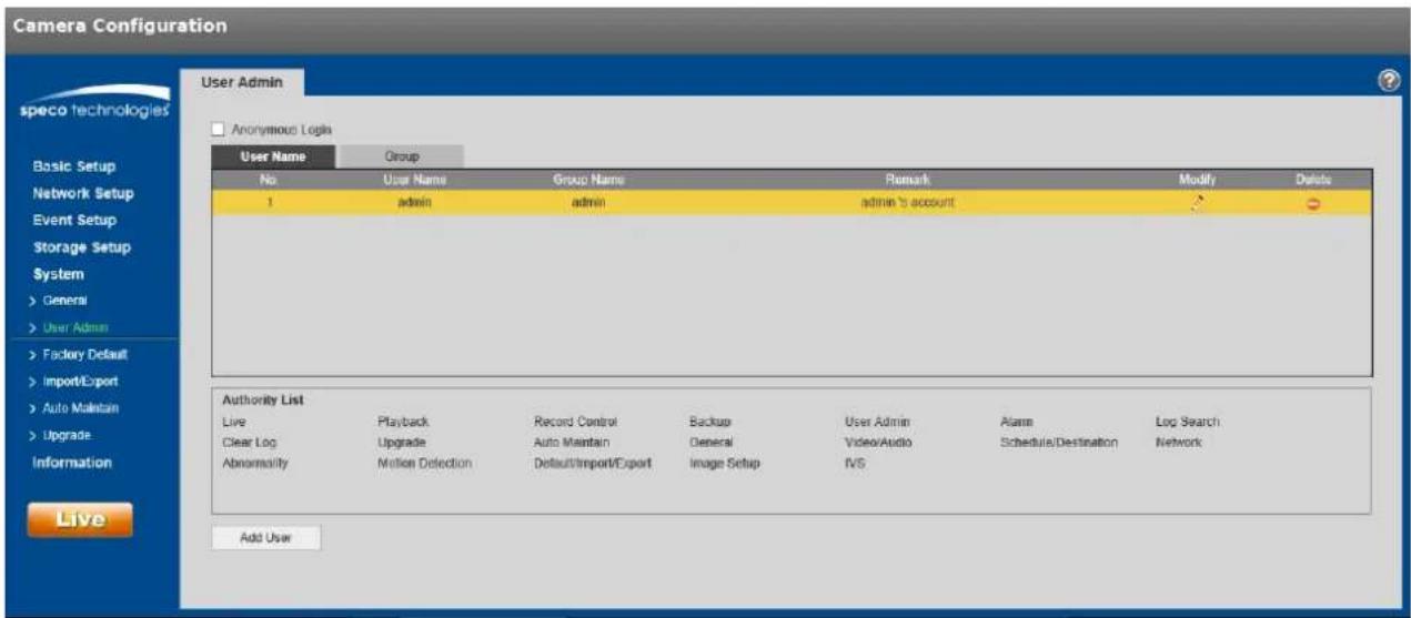
text_image
Camera Configuration User Admin speco technologies Anonymous Logs User Name Group No User Name Group Name Remark Modify Delete 1 adults adults admin's account Authority List Live Playback Record Control Backup User Admin AlarmLoad Search Clear Log Upgrade Auto Maintain General Video/Audio Schedule/Destination Network Abnormality Motion Detection Default/Import/Export kilograms setup IVS Add UserFigure 5-66
Enable anonymous login: If enabled, no username and password are required to view the live stream. Click on Logout on the live view page to go back to the login page.
Add user: For creang a user and adding the user to a group. User rights can also be set. See Figure 5-67. Note that a user's rights cannot not exceed the rights of the group.
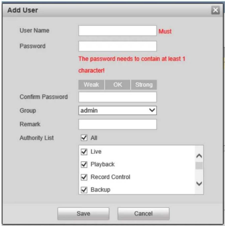
text_image
Add User User Name Must Password The password needs to contain at least 1 character! Weak OK Strong Confirm Password Group adults Remark Authority List All Live Playback Record Control Backup Save CancelFigure 5-67
5.5.2.2 Group
The group management interface is shown as in Figure 5-68.

text_image
Camera Configuration User Admin speco technologies Anonymous Login User Name Group No Group Name Remark Modify Details 1 adults administrator group 2 user User group Authority List Live Playback Record Control Backup User Admin Alarm Log Search Clear Log Upgrade Auto Maintain General Video/Audio Schedule/Destination Network Abnormally Motion Detection Default/Import/Exportwerage Setup IVS Add GroupFigure 5-68
Add group: See Figure 5-69.
Enter the group name and then check the applicable boxes for the rights of the group.

text_image
Add Group Group Must Remark Authority List All Live Playback Record Control Backup Save CancelFigure 5-69
5.5.3 Factory Default
The factory default interface is shown in Figure 5-70.
The "Default" opon resets every seng of the device while the "Keep Network Sengs" opon retains pernent network setup informaon of the device.
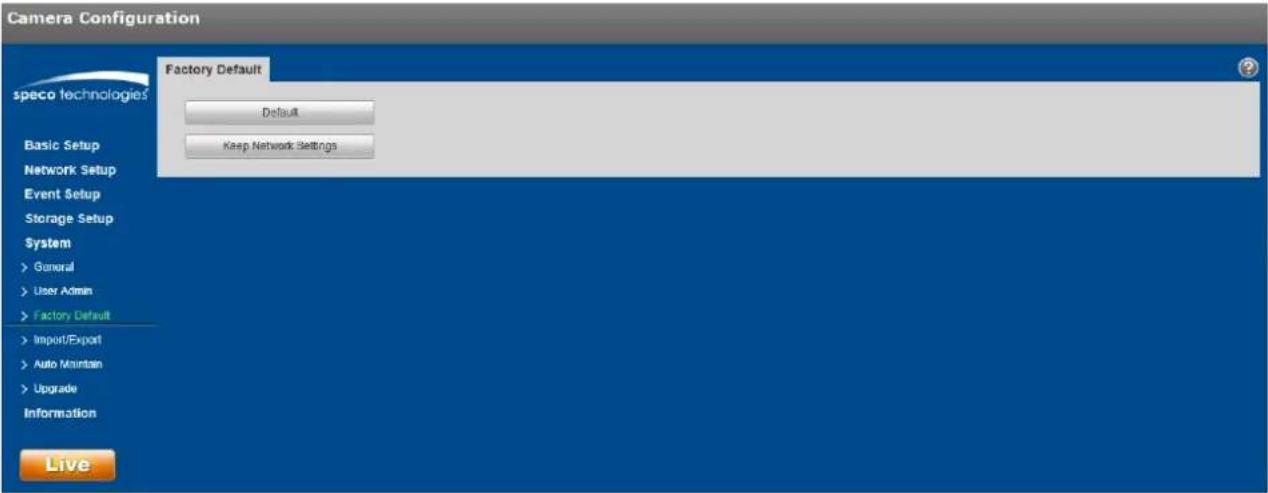
text_image
Camera Configuration speco technologies Factory Default Default Keep Network Settings Basic Setup Network Setup Event Setup Storage Setup System > General > User Admin > Factory Default > Import/Export > Auto Maintain > Upgrade Information LiveFigure 5-70
5.5.4 Import/Export
The interface is shown in Figure 5-71. This can be used to set up mulple devices of the same model with the same system conguraon.
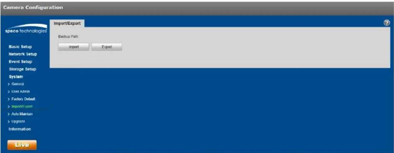
text_image
Camera Configuration speco technologies Import/Export Backup Path Import Export Basic Setup Network Setup Event Setup Storage Setup System > General > User Admin > Factory Default > Import/Export > Auto Maintain > Upgrade Information LiveFigure 5-71
| Parameter | Funcon |
| Import | Import a conguraon le to the device. |
| Export | Export the current conguraon of the device to the local PC. |
5.5.5 Upgrade
The upgrade interface is shown in Figure 5-72. Firmware of the device can be updated here.
Select the applicable rmware le (le extension is ".bin") and then click the Upgrade buon to begin the rmware update.
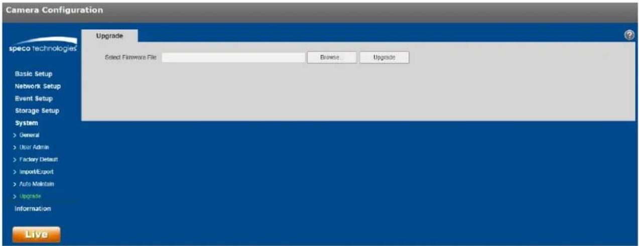
text_image
Camera Configuration speco technologies Upgrade Select Firmware File Browse... Upgrade Basic Setup Network Setup Event Setup Storage Setup System > General > User Admin > Factory Default > Import/Export > Auto Maintain > Upgrade Information LiveFigure 5-72
5.6 Informaon
5.6.1 Version
The version interface is shown in Figure 5-73.
In this secon, the model number, rmware version and date, serial number of the device, and tech support contact informaon are shown.
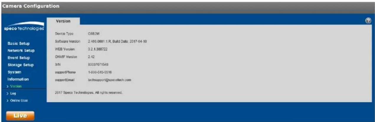
text_image
Camera Configuration speco technologies Basic Setup Network Setup Event Setup Storage Setup System Information > Version > Leg > Online User Version Device Type 08B2M Software Version 2.460.0001.1.R, Build Date: 2017-04-10 WEB Version 3.2.1.388722 ONVIF Version 2.42 S/N 80037071548 supportPhone 1-800-045-5516 supportEmail techsupport@specotech.com 2017 Speco Technologies. All rights reserved. LiveFigure 5-73
5.6.2 Log
See Figure 5-74 for the system log interface.

text_image
Camera Configuration speco technologies Basic Setup Network Setup Event Setup Storage Setup System Information > Version > Log > Online User Live Log Start Time 10-12-2017 04:23:03 PM End Time 10-13-2017 04:23:03 PM Type All Search No Log Time User Name Event Detailed Information Time: User Name: Type: Control: Backup ClearFigure 5-74
Please refer to the following sheet for log parameter informaon.
| Parameter | Funcon |
| Start me | Set the start me of the requested log. |
| End me | Set the end me of the requested log. |
| Type | Select the type of informaon to display. |
| Log informaon | Select one item to view detailed informaon about the entry. |
| Backup | Can be used to back up log les to the PC. |
5.6.3 Online User
The online user interface is shown in Figure 5-75.
Informaon about all users who are currently logged into the device is shown.

text_image
Camera Configuration Online User speco technologies No. Username User Local Group IP Address User Login Time 1 adults adults 192 168 56 101 16-13-2017 03:11:49 PM Refresh LiveFigure 5-75
Note:
● This manual is for reference only. Slight dierences may be found in depending on the model.
● All informaon described here is subject to change without prior written noce.
- All trademarks and registered trademarks menoned are the properes of their respective owners.
- If further explanaon is needed, please contact Speco Technologies technical support.
Speco Technologies
200 New Highway
Amityville, NY 11701
Phone: 631-957-8700
Email: techsupport@specotech.com
Web: hp://www.specotech.com