SC812i-420C - Server Supermicro - Free user manual and instructions
Find the device manual for free SC812i-420C Supermicro in PDF.

User questions about SC812i-420C Supermicro
0 question about this device. Answer the ones you know or ask your own.
Ask a new question about this device
Download the instructions for your Server in PDF format for free! Find your manual SC812i-420C - Supermicro and take your electronic device back in hand. On this page are published all the documents necessary for the use of your device. SC812i-420C by Supermicro.
USER MANUAL SC812i-420C Supermicro
natural_image
Line drawing of a server rack unit with multiple ports and ventilation slots (no text or symbols)The SC812/SC812L Chassis Series
Installation Guide
Rev. 1.0
Table of Contents
Chapter I: Introduction 1-3
A. Front Panel Connectors 1-3
B. Front Panel LED Indicators 1-3
C. Front Panel LED Descriptions 1-3
D. Back Panel Connectors 1-4
E. An Important Note to the User 1-4
Chapter 2: Installation Procedures....2-1
Section 1: Installing components into the Chassis....2-1
A. Removing the Top Cover from the SC812/SC812L Chassis ..... 2-1
B-1. Removing and Installing the Disk Drive 2-2
B-2. Removing and Installing the Hard Drive Disks 2-3
C-1. Rail Installation 2-4
C-2. Installing Chassis Rails 2-5
D-1. Rack Installation for the Traditional 1U Design 2-7
D-2. Rack Installation for the Open-Rack Design 2-9
Section 2: SCSI (Super) GEM Driver Installation Instructions for the Windows OS.... 2-12
User's Guide Revision: Revision 1.0
Release Date: July 28, 2006
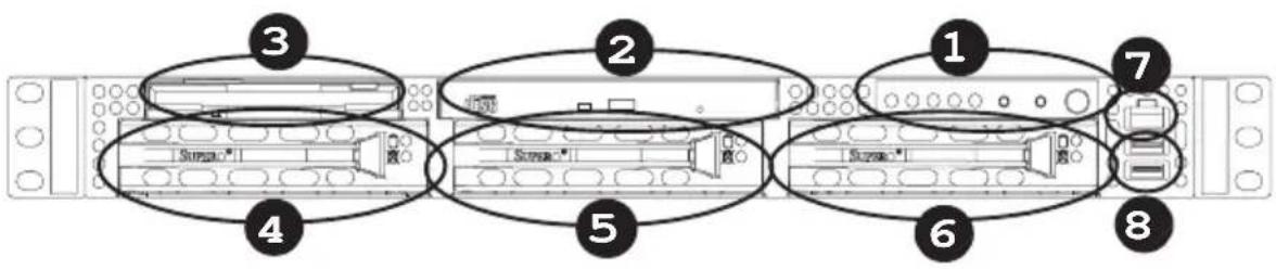
Chapter 1: Introduction
A. Front Panel Connectors
text_image
Diagram of a rack-mounted server rack with labeled components including audio, sound, and ports- Front Panel LED Indicators (See Section B Below.)
- CD-ROM
- Floppy
- HDD Tray
- HDD Tray
- HDD Tray
- RJ45 (COM) Port
- USB 2.0 Ports (x2)
B. Front Panel LED Indicators
C. Front Panel LED Descriptions
| LED Button Color Condition Description | |||
| Green | On System Off System On Power | ||
| Off System Off | |||
| Amber | Blink | HDD Activity HDD | |
| Off | No Activity | ||
| LAN1 & LAN2 | Green | On Linked | |
| Blink | LAN Activity | ||
| Off | Disconnected | ||
| Overheat | Red | On | System Overheat |
| Off | System Normal | ||
D. Back Panel Connectors

text_image
Diagram of a server rack with numbered components, highlighting internal hardware layout and ports.- Expansion Slot
- Expansion Slot
- Power Module
- Keyboard
- Mouse
- USB 2.0 Connectors (x2)
7.COM Port - LAN Ports (x2)
- VGA Connector
- SCSI External Port
E. An Important Note to the User
All images and layouts shown in this manual were based upon the latest chassis Revision available at the time of publishing of this manual. The chassis you've received may or may not look exactly the same as the graphics shown in this manual.
Chapter 2: Installation Procedures
Section 1: Removing and Installing the components
Before installing any components, replacing chassis fans or accessing the motherboard, you will need to remove the top cover, the front bezel, the fans and the air shrouds from the chassis first.
A. Removing the top cover from the chassis
Procedures
-
Press the release tabs to release the top cover from its locking position.
-
Slide the top cover out from the chassis as shown below:
-
Slide the top cover out from the chassis

natural_image
Technical line drawing of a server rack with mounting hardware and a directional arrow indicating motion (no text or symbols)-
Press the release buttons
-
You can now lift the side cover up and off the chassis.
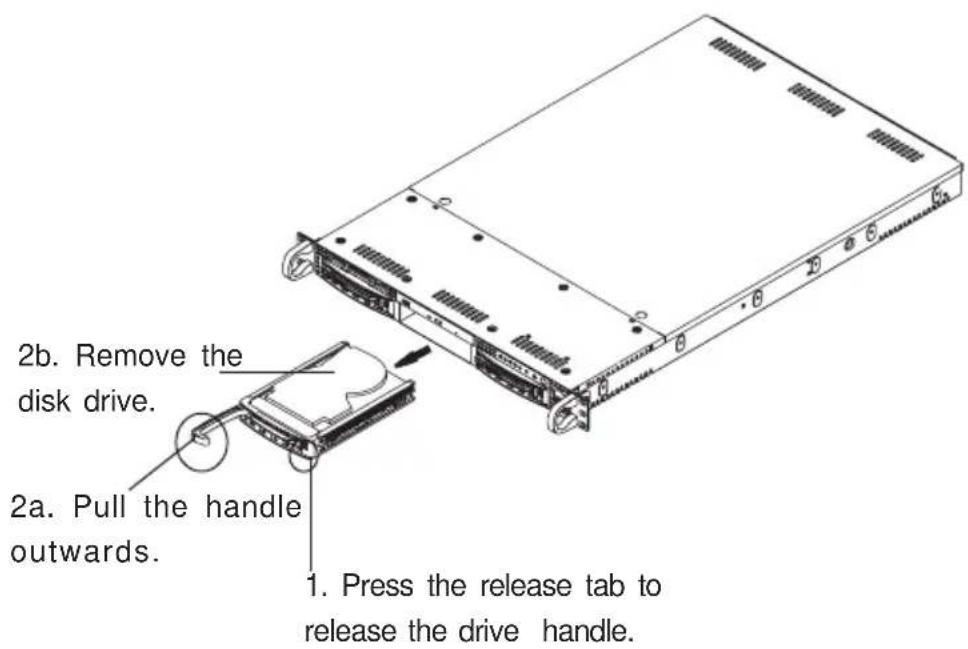
B-1. Removing/Installing the Disk Drive
(*Note: For the SC812S-420/400/400C models.)
Procedures:
- Press the release tab on the right side of the disk drive to release the disk drive handle.
- Pull the disk drive handle outwards and remove it from the chassis.
text_image
2b. Remove the disk drive. 2a. Pull the handle outwards. 1. Press the release tab to release the drive handle.(*Note: Reverse the steps listed above to install the disk drive into the chassis.)
B-2. Removing/Installing the Hard Drive Disks
(*Note: For the SC812L Chassis.)
B-2 Procedures (Removing the HDD Drive from the SC812L):
- Remove the screw as shown below to detach the HDD drive tray from the chassis.
- Push the HDD drive tray backwards until the drive tray is released from the two fastening tabs located in front of the chassis.
-
Once the HDD drive tray is detached from the chassis, remove the two screws on each side of the drive tray to separate the HDD from the drive tray as shown below.
-
Remove the screws to loosen the HDD from the drive tray.
-
Remove the screw.

text_image
to touch the H2D work the drive tray. 2. Push the drive tray back- wards to release it from the chassis.- Push the drive tray backwards to release it from the chassis.
(*Note: Reverse the steps listed above to install the HDD into the chassis.)
C-1. Rail Installation
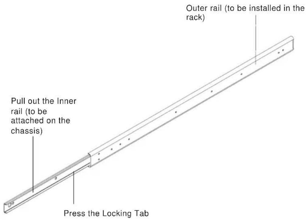
You should receive two sets of rail assemblies. Each set of the rail assembly includes the following:
- An inner fixed chassis rail (A) that is attached to the chassis.
- An outer fixed rack rail (B) which is affixed to the rack.
- A sliding rail guide (C) that is sandwiched between the chassis rail and the rack rail. The sliding guide should remain attached to the outer fixed rack rail (B). However, the inner chassis rail(A) and the outer rack rail (B) must be detached from each other to install.
C-2. Installing Chassis Rails (-Inner Rails)
Please make sure that the chassis covers and chassis rails are installed on the chassis before you install the chassis into the rack.

To avoid personal injury and property damage, please carefully follow all the safety steps listed below:
Before installing the Chassis rails:
- Enclose the chassis with chassis covers.
- Unplug the AC power cord(s).
- Remove all external devices and connectors.
Procedures to Install Chassis Rails
- Included in the shipping package are a pair of rail assemblies. In each rail assembly, locate the inner rail and the outer rail.
- Press the locking tab to release the inner rail from its locking position and pull out the inner rail from the rail assembly. (*The inner rails are to be attached to the chassis and the outer rails are to be installed in the rack.)
text_image
Outer rail (to be installed in the rack) Pull out the Inner rail (to be attached on the chassis) Press the Locking Tab- Locate the five holes on each side of the chassis and locate the five corresponding holes on each of the inner rail.
text_image
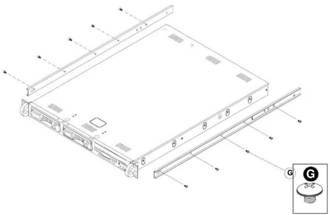
Technical diagram of a server rack with labeled components and an inset showing a G button.-
Attach an inner rail to each side of the chassis and secure the inner rail to the chassis by inserting five Type G screws through the holes on the chassis and the inner rail. (Refer to Page 2-1 for the Type G screw.)
-
Repeat the above steps to install other rail on the chassis.
D-1 Rack Installation for the Traditional 1U Design
After you have installed the inner rails on the chassis, you are ready to install the outer rails of rail assemblies to the rack.
(* The rails are designed to fit in the racks with the depth of 28" to 33".)
Procedures
-
In the package, locate a pair of front (-short) and rear (-long) brackets. Please note that the brackets are marked with Up/Front Arrows (-front) and Up/Rear arrows (-rear).
-
Secure the front (-short) bracket (marked with the Up/Front arrows) to the outer rail with two Type G screws.
-
Attach the rear (-long) bracket to the other end of the outer rail and secure the rear (long) bracket to the outer rail with a Type G screw as shown below.
-
Measure the depth of your rack and adjust the length of the rails accordingly.
-
Repeat the same steps install the other outer rail on the chassis.
-
Secure both outer rail assemblies to the rack with Type H screws and Type I washers.
text_image
Type I washers. ④ ③ ⑥ ① G H G ② G- Slide the SC812/SC812L chassis into the rack as shown below:
(The SC812/SC812L may not slide into the rack smoothly or easily when installed the first time. However, some adjustment to the slide assemblies might be needed for easy installation.)
- You will need to release the safety taps on both sides of the chassis in order to completely remove the chassis out of the rack.
natural_image
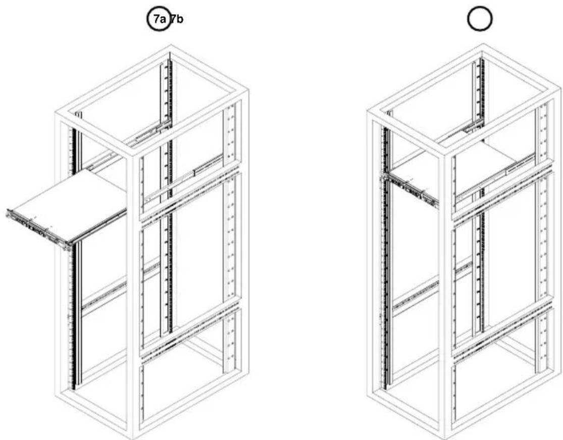
Technical line drawings of two modular server racks with labeled components (7a, 7b), no text or symbols present.D-2 Rack Installation for the Open-Rack Design
After you have installed the inner rails on the chassis, you are ready to install the outer rails of rail assemblies to the rack.
(* The rails are designed to fit in the racks with the depth of 28" to 33".)
Procedures
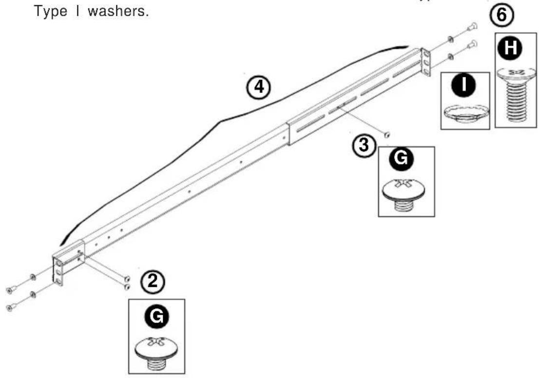
- In the package, locate a pair of front (-short) and rear (-long) brackets. Please note that the brackets are marked with Up/Front Arrows (-front) and Up/Rear arrows (-rear).
- Secure the front (-short) bracket (marked with the Up/Front arrows) to the outer rail with two Type G screws as shown below:

natural_image
Technical line drawing of a long metal beam supported by two vertical supports, with an inset showing a screw base and labeled component G (no text or symbols present)-
Attach the front (-short) bracket to the front end of the rack, and secure it to the rack with two Type H screws and Type I washers as shown below.
-
Attach the rear (-long) bracket to the rear end of the rack, and secure it to the rack with two Type H screws and Type I washers as shown below. Repeat the same steps to install the other outer rail to the other side of rack.

text_image
Technical diagram illustrating assembly steps of a mechanical bracket with labeled components and exploded views- Measure the depth of your rack and adjust the length of the rails accordingly. Then, secure the rails to the chassis with Type G screws.
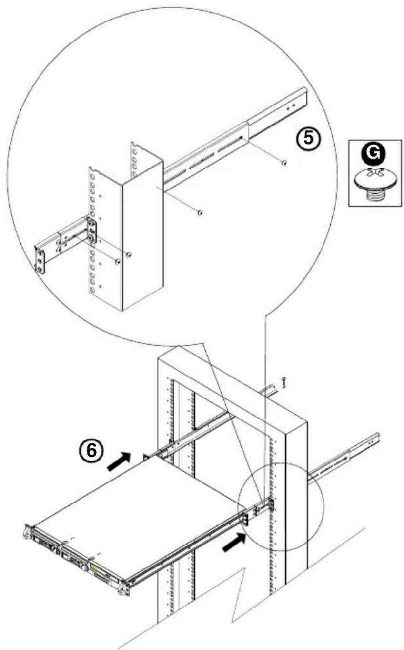
- Slide the inner rails which are attached to the chassis to into the outer rails on the rack.
text_image
Technical diagram showing assembly steps of a server rack with labeled components and directional arrows indicating motion.Section 2: SCSI (Super) GEM Driver Installation Instructions for the Windows OS (\*For the SC812S Models only)
Please refer to the following instructions to install the SCSI GEM Driver for the Windows OS systems.
(*Note: This driver is not necessary for other Operating Systems. If you have two SCA backplanes, you will need to install the driver twice.)
The driver is located on the Super Micro motherboard driver CD or is available for download from our FTP site: ftp://ftp.supermicro.com/driver/Qlogic/
Follow the procedure below to install this driver to your system.
Installing the driver:
1) Right click on "My Computer" and choose "Property".
2) Select "Hardware" tab and click on "Device Manager".
3) Open "Other Devices" or wherever "GEM318" is on.
4) Right click on this device and choose "Property".
5) Click on "Driver" tab and choose "Update Driver".
6) Click "Next" 2 times, uncheck both "Floppy disk drives" and "CD-ROM drives". Then, select the item- "Specify a location," and choose "Next".
7) Click on "Browse" and choose D drive or wherever Supermicro Setup CD is in.
8) Choose "Qlogic" folder and click on "Open".
9) System will automatically detect GEM318 and install the drive from this point on.
or,
1) Right click the "My Computer" icon on your desktop and choose Properties.
2) Click on the Hardware tab and click on "Device Manager" to bring up the list of system devices.
3) You may see one or two yellow question marks (?) that read QLogic GEM354 or GEM318 SCSI Processor Device. Right click on these, and choose to uninstall. If two such question marks are present, uninstall both.
4) Click on Action tab and choose "Scan for Hardware Changes". The Hardware Wizard program should start up. Click "Next".
5) At the first prompt, choose "Display a list of known device drivers for the device so that I can choose a specific driver" and click "Next".
6) Choose "Other Devices" and click Next.
7) Choose "Have Disk", and specify your floppy drive location in the options box. Then, click "Next".
8) Highlight "Enclosure Services Device" and click "Next".
9) Ignore the warning prompt by clicking "Yes".