SuperServer 5018D4-AR12L - Server Supermicro - Free user manual and instructions
Find the device manual for free SuperServer 5018D4-AR12L Supermicro in PDF.

User questions about SuperServer 5018D4-AR12L Supermicro
0 question about this device. Answer the ones you know or ask your own.
Ask a new question about this device
Download the instructions for your Server in PDF format for free! Find your manual SuperServer 5018D4-AR12L - Supermicro and take your electronic device back in hand. On this page are published all the documents necessary for the use of your device. SuperServer 5018D4-AR12L by Supermicro.
USER MANUAL SuperServer 5018D4-AR12L Supermicro
natural_image
Pure electrical circuit lines without any symbolsUSER'S MANUAL
1.0b
The information in this User's Manual has been carefully reviewed and is believed to be accurate. The vendor assumes no responsibility for any inaccuracies that may be contained in this document, makes no commitment to update or to keep current the information in this manual, or to notify any person or organization of the updates. Please Note: For the most up-to-date version of this manual, please see our web site at www.supermicro.com.
Super Micro Computer, Inc. ("Supermicro") reserves the right to make changes to the product described in this manual at any time and without notice. This product, including software and documentation, is the property of Supermicro and/or its licensors, and is supplied only under a license. Any use or reproduction of this product is not allowed, except as expressly permitted by the terms of said license.
IN NO EVENT WILL SUPERMICRO BE LIABLE FOR DIRECT, INDIRECT, SPECIAL, INCIDENTAL, SPECULATIVE OR CONSEQUENTIAL DAMAGES ARISING FROM THE USE OR INABILITY TO USE THIS PRODUCT OR DOCUMENTATION, EVEN IF ADVISED OF THE POSSIBILITY OF SUCH DAMAGES. IN PARTICULAR, SUPERMICRO SHALL NOT HAVE LIABILITY FOR ANY HARDWARE, SOFTWARE, OR DATA STORED OR USED WITH THE PRODUCT, INCLUDING THE COSTS OF REPAIRING, REPLACING, INTEGRATING, INSTALLING OR RECOVERING SUCH HARDWARE, SOFTWARE, OR DATA.
Any disputes arising between manufacturer and customer shall be governed by the laws of Santa Clara County in the State of California, USA. The State of California, County of Santa Clara shall be the exclusive venue for the resolution of any such disputes. Super Micro's total liability for all claims will not exceed the price paid for the hardware product.
FCC Statement: This equipment has been tested and found to comply with the limits for a Class A digital device pursuant to Part 15 of the FCC Rules. These limits are designed to provide reasonable protection against harmful interference when the equipment is operated in a commercial environment. This equipment generates, uses, and can radiate radio frequency energy and, if not installed and used in accordance with the manufacturer's instruction manual, may cause harmful interference with radio communications. Operation of this equipment in a residential area is likely to cause harmful interference, in which case you will be required to correct the interference at your own expense.
California Best Management Practices Regulations for Perchlorate Materials: This Perchlorate warning applies only to products containing CR (Manganese Dioxide) Lithium coin cells. "Perchlorate Material-special handling may apply. See www.dtsc.ca.gov/hazardouswaste/perchlorate"
WARNING: Handling of lead solder materials used in this product may expose you to lead, a chemical known to the State of California to cause birth defects and other reproductive harm.
Manual Revision 1.0b
Release Date: August 3, 2016
Unless you request and receive written permission from Super Micro Computer, Inc., you may not copy any part of this document.
Information in this document is subject to change without notice. Other products and companies referred to herein are trademarks or registered trademarks of their respective companies or mark holders.
Copyright © 2016 by Super Micro Computer, Inc.
All rights reserved.
Printed in the United States of America
Preface
About This Manual
This manual is written for professional system integrators and PC technicians. It provides information for the installation and use of the SuperStorage Server 5018D2-AR12L/5018D4-AR12L/5018D8-AR12L. Installation and maintenance should be performed by experienced technicians only.
Manual Organization
Chapter 1: Introduction
The first chapter provides a checklist of the main components included with the server system and describes the main features of the X10SDV-2C-7TP4F/X10S-DV-4C-7TP4F/X10SDV-7TP4F motherboard and the SC801LTS-R406P chassis.
Chapter 2: Server Installation
This chapter describes the steps necessary to install the SuperStorage Server 5018D2-AR12L/5018D4-AR12L/5018D8-AR12L into a rack and check out the server configuration prior to powering up the system.
Chapter 3: Standardized Warning Statements
Refer here for details on the system interface, which includes the functions and information provided by the control panel on the chassis as well as other LEDs located throughout the system.
Chapter 4: Standardized Warning Statements
You should thoroughly familiarize yourself with this chapter for a general overview of safety precautions that should be followed when installing and servicing the SuperStorage Server 5018D2-AR12L/5018D4-AR12L/5018D8-AR12L.
Chapter 5: Advanced Motherboard Setup
Chapter 5 provides detailed information on the X10SDV-2C-7TP4F/X10SDV-4C-7TP4F/X10SDV-7TP4F motherboard, including the locations and functions of connections, headers and jumpers. Refer to this chapter when adding or removing processors or main memory and when reconfiguring the motherboard.
Chapter 6: Advanced Chassis Setup
Refer to Chapter 6 for detailed information on the SC801LTS-R406P server chassis. You should follow the procedures given in this chapter when installing, removing or reconfiguring SATA drives and when replacing system power supply units and cooling fans.
Chapter 7: BIOS
The BIOS chapter includes an introduction to BIOS and provides detailed information on running the CMOS Setup Utility.
Appendix A: BIOS Error Beep Codes
Appendix B: System Specifications
Notes
Table of Contents
Chapter 1 Introduction
1-1 Overview 1-1
1-2 Motherboard Features.... 1-2
Processors 1-2
Memory 1-2
SAS/SATA.... 1-2
PCI Expansion Slots 1-2
Rear I/O Ports 1-2
Graphics Controller 1-2
1-3 Server Chassis Features 1-3
System Power 1-3
Hard Drive Subsystem....1-3
Front Control Panel.... 1-3
System Fans 1-3
1-4 Contacting Supermicro.... 1-5
Chapter 2 Server Installation
2-1 Overview 2-1
2-2 Unpacking the System....2-1
2-3 Preparing for Setup....2-1
Choosing a Setup Location....2-1
2-4 Warnings and Precautions 2-2
Rack Precautions 2-2
Server Precautions....2-2
Rack Mounting Considerations 2-3
Ambient Operating Temperature 2-3
Reduced Airflow 2-3
Mechanical Loading 2-3
Circuit Overloading....2-3
Reliable Ground 2-3
2-5 Installing the System into a Rack 2-4
Installing the Chassis into a Standard Rack....2-4
Assembling the Outer Rails 2-5
Installing the Outer Rails onto the Rack 2-6
Sliding the Chassis onto the Rack....2-7
Chapter 3 System Interface
3-1 Overview 3-1
3-2 Control Panel Buttons 3-2
Power 3-2
Reset 3-2
3-3 Control Panel LEDs 3-2
UID LED 3-2
NIC 3-2
HDD....3-3
3-4 Power Supply LEDs 3-3
Chapter 4 Standardized Warning Statements for AC Systems
4-1 About Standardized Warning Statements 4-1
Warning Definition 4-1
Installation Instructions....4-4
Circuit Breaker 4-5
Power Disconnection Warning 4-6
Equipment Installation 4-8
Restricted Area....4-9
Battery Handling....4-10
Redundant Power Supplies 4-12
Backplane Voltage 4-13
Comply with Local and National Electrical Codes....4-14
Product Disposal 4-15
Hot Swap Fan Warning 4-16
Power Cable and AC Adapter 4-18
Chapter 5 Advanced Motherboard Setup
5-1 Handling the Motherboard 5-1
Precautions 5-1
5-2 Connecting Cables....5-2
Connecting Data Cables 5-2
Connecting Power Cables 5-2
Connecting the Control Panel....5-2
5-3 I/O Ports 5-3
5-4 Installing Memory 5-4
5-5 Adding PCI Expansion Cards 5-5
5-6 Motherboard Details....5-6
X10SDV Series Quick Reference 5-7
5-7 Connector Definitions 5-9
5-8 Jumper Settings 5-16
5-9 Onboard Indicators....5-19
5-10 SATA/SAS Ports 5-21
5-11 Installing Drivers....5-22
SuperDoctor® 5 5-23
5-13 Onboard Battery 5-24
Chapter 6 Advanced Chassis Setup
6-1 Static-Sensitive Devices....6-1
Precautions 6-1
Unpacking 6-1
6-2 Control Panel 6-2
6-3 Removing Power from the System 6-2
6-4 Removing the Chassis Cover 6-3
6-5 Installing and Replacing Hard Drives.... 6-4
6-6 System Fans 6-5
6-6 Installing an Expansion Card....6-6
6-7 Power Supply 6-8
Replacing the Power Supply....6-8
Chapter 7 BIOS
7-1 Introduction....7-1
Starting BIOS Setup Utility....7-1
How To Change the Configuration Data....7-1
How to Start the Setup Utility 7-2
7-2 Main Setup....7-2
7-3 Advanced Setup Configurations.... 7-4
7-4 Event Logs 7-28
7-5 IPMI 7-30
7-6 Security Settings 7-33
7-7 Boot Settings.... 7-36
7-8 Save & Exit 7-38
Appendix A BIOS Error Beep Codes
Appendix B System Specifications
Chapter 1
Introduction
1-1 Overview
The SuperStorage 5018D2-AR12L/5018D4-AR12L/5018D8-AR12L is a storage system comprised of two main subsystems: the SC801LTS-R406P 1U chassis and the X10SDV-2C-7TP4F/X10SDV-4C-7TP4F/X10SDV-7TP4F single processor motherboard. Please refer to our website for information on operating systems that have been certified for use with the system (www.supermicro.com).
In addition to the motherboard and chassis, various hardware components have been included with the 5018D2-AR12L/5018D4-AR12L/5018D8-AR12L, as listed below:
• Six 4-cm PWM fans (FAN-0154L4)
• One riser card (RSC-RR1U-E8)
- SATA accessories:
Two HDD backplanes (BPN-SAS-801T-A2)
Two HDD backplanes (BPN-SAS-801T-A4)
Twelve fixed 3.5" HDD brackets (MCP-220-00134-0N)
Optional: two brackets for single/dual 2.5" drives (MCP-220-00137-0N)
• One rack rail kit (MCP-290-00066-0N)
Note: For your system to work properly, please follow the links below to download all necessary drivers/utilities and the user's manual for your server.
• Supermicro product manuals: http://www.supermicro.com/support/manuals/
• Product drivers and utilities: ftp://ftp.supermicro.com
- Product safety info: http://www.supermicro.com/about/policies/safety_information.cfm
- If you have any questions, please contact our support team at: support@supermicro.com
1-2 Motherboard Features
The SuperStorage Server 5018D2-AR12L/5018D4-AR12L/5018D8-AR12L is built around the X10SDV-2C-7TP4F/X10SDV-4C-7TP4F/X10SDV-7TP4F, a single processor motherboard. Below are the main features of the X10SDV-2C-7TP4F/X10SDV-4C-7TP4F/X10SDV-7TP4F. See Section 5-6 for a layout and cariances of the three motherboards.
Processors
The X10SDV-2C-7TP4F/X10SDV-4C-7TP4F/X10SDV-7TP4F supports a single Intel® Xeon/Pentium® D-1500 Family SoC embedded processor (SoC = System on a Chip).
Memory
The X10SDV-2C-7TP4F/X10SDV-4C-7TP4F/X10SDV-7TP4F has four DIMM slots that can support up to 128 GB of ECC RDIMM (Registered DIMM) or 64 GB of ECC/non-ECC UDIMM (Unregistered DIMM) DDR4-2133/1866/1600 memory. See Chapter 5 for details.
SAS/SATA
A SATA controller is integrated into the chipset to provide six SATA 3.0 (6/Gbps) ports. In addition, an LSI 2116 controller is included on the motherboard to provide sixteen SAS2.0 ports.
PCI Expansion Slots
The X10SDV-2C-7TP4F/X10SDV-4C-7TP4F/X10SDV-7TP4F has one M.2 PCI-E 3.0 x4 slot, an M Key for 2242/2280/22110 SSDs and one mini PCI-E 2.0 x1 slot with mSATA support (Mux with I-SATA5).
Rear I/O Ports
The rear I/O ports include a VGA port, two USB 3.0 ports, two Gb Ethernet (RJ45) LAN ports, a dedicated IPMI LAN port and two 10 Gb (SPF+) Ethernet LAN ports
Graphics Controller
The X10SDV-2C-7TP4F/X10SDV-4C-7TP4F/X10SDV-7TP4F features an integrated AST 2400 graphics controller.
1-3 Server Chassis Features
The SC801LTS-R406P is a proprietary form factor chassis designed to be used in a 1U rackmount configuration. The following is a general outline of the main features of the SC801LTS-R406P server chassis.
System Power
The chassis features a redundant 400W power supply consisting of two separate power supply modules. If one of the power supply modules fail, the system will continue running.
Hard Drive Subsystem
A total of twelve 3.5" internal hard drives are supported by the system. These are hot-swappable drives with the use of an optional chassis cable arm, which keeps power applied to the system when extended from the rack.
Front Control Panel
The control panel on the SC801LTS-R406P provides you with system monitoring and control. LEDs indicate HDD activity, network activity and a UID (Unit Identifier) LED. A main power button and a system reset button are also included.
System Fans
The system includes six 4-cm PWM cooling fans. Fan speed can vary with the internal system temperature (controlled by IPMI).
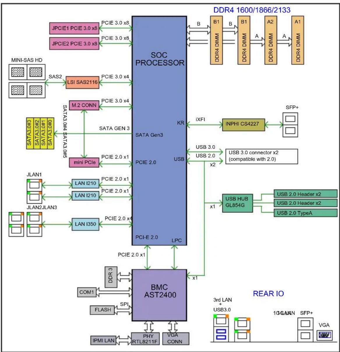
Figure 1-1. X10SDV Flex ATX Series: System Block Diagram
Note: This is a general block diagram. Please see Chapter 5 for details.
flowchart
graph TD
    subgraph SOC_PROCESSOR
        A["MINI-SAS HD"] -->|SAS2| B["LSI SAS2116"]
        B -->|PCIE 3.0 x4| C["SATA Gen3"]
        C -->|PCIE 3.0 x4| D["M.2 CONN"]
        D -->|PCIE 3.0 x4| E["mini PCIe"]
        E -->|PCIE 2.0 x1| F["JLAN1"]
        F -->|PCIE 2.0 x1| G["JLAN2JLAN3"]
        G -->|PCIE 2.0 x1| H["LAN I210"]
        H -->|PCIE 2.0 x1| I["LAN I210"]
        I -->|PCIE 2.0 x1| J["PCI-E 2.0"]
        J -->|LPC| K["BMC AST2400"]
        K -->|PCIE 2.0 x1| L["IPMI LAN"]
        L --> M["PHY RTL8211F"]
        M --> N["VGA CONN"]
    end

    subgraph BSC
        O["DDR4 DIMM"] --> P["B1"]
        P --> Q["B1"]
        Q --> R["A2"]
        R --> S["A1"]
        S --> T["DDR4 DIMM"]

    end

    subgraph SFP+
        U["INPHI CS4227"] --> V["SFP+"]

        W["USB 3.0 connector x2 (compatible with 2.0)"]
        X["USB HUB GL854G"] --> Y["USB 2.0 Header x2"]
        Y --> Z["USB 2.0 Header x2"]
        Z --> AA["USB 2.0 TypeA"]

    end

    subgraph REAR_IO
        AB["3rd LAN + USB3.0"] --> AC["1GAMAN SFP+"]
        AC --> AD["VGA"]
    end

    subgraph SATA Gen3
        AE["SATA Gen3"] --> AF["mini PCIe"]
        AF --> AG["SATA GEN 3"]
        AG --> AH["mini PCIe"]
        AH --> AI["SATA GEN 3"]
        AI --> AJ["mini PCIe"]
    end

    subgraph BMC AST2400
        AK["PCI-E 2.0"] --> AL["RPCE 2.0"]
        AL --> AM["LPC"]
        AM --> AN["PCIE 2.0 x1"]
        AN --> AO["PCIE 2.0 x1"]
        AO --> AP["COM1"]
        AP --> AQ["DDR 3"]
        AQ --> AR["FLASH"]
        AR --> AS["SPI"]
        AS --> AT["IPMI LAN"]
        AT --> AU["PHY RTL8211F"]
        AU --> AV["VGA CONN"]
    end

    subgraph DDR4_1600/1866/2133
    AW["DDR4 DIMM"] <--> AX["B1"]
    AX <--> AY["B1"]
    AY <--> AZ["A2"]
    AZ <--> BA["A1"]
    BA <--> BB["DDR4 DIMM"]

    BC["iXFI"] --> AD
    AD --> AL
    AL --> AN
    style SOC_PROCESSOR fill:#99CCFF,stroke:#333
    style SFP+
    style REAR_IO fill:#FFD700,stroke:#333
1-4 Contacting Supermicro
Headquarters
Address: Super Micro Computer, Inc.
980 Rock Ave.
San Jose, CA 95131 U.S.A.
Tel: +1 (408) 503-8000
Fax: +1 (408) 503-8008
Email: marketing@supermicro.com (General Information)
support@supermicro.com (Technical Support)
Web Site: www.supermicro.com
Europe
Address: Super Micro Computer B.V.
's-Hertogenbosch, The Netherlands
Tel: +31 (0) 73-6400390
Fax: +31 (0) 73-6416525
Email: sales@supermicro.nl (General Information)
support@supermicro.nl (Technical Support)
rma@supermicro.nl (Customer Support)
Web Site: www.supermicro.nl
Asia-Pacific
Address: Super Micro Computer, Inc.
3F, No. 150, Jian 1st Rd.
Zhonghe Dist., New Taipei City 235
Taiwan (R.O.C)
Tel: +886-(2) 8226-3990
Fax: +886-(2) 8226-3992
Email: support@supermicro.com.tw
Web Site: www.supermicro.com.tw
Notes
Chapter 2
Server Installation
2-1 Overview
This chapter provides a quick setup checklist to get your SuperStorage 5018D2-AR12L/5018D4-AR12L/5018D8-AR12L up and running. Following these steps in the order given should enable you to have the system operational within a minimum amount of time. This quick setup assumes that your system has come to you with the processors and memory preinstalled.
2-2 Unpacking the System
You should inspect the box the system was shipped in and note if it was damaged in any way. If the server itself shows damage you should file a damage claim with the carrier who delivered it.
Decide on a suitable location for the rack unit that will hold the system. It should be situated in a clean, dust-free area that is well ventilated. Avoid areas where heat, electrical noise and electromagnetic fields are generated. You will also need it placed near a grounded power outlet. Read the Rack and Server Precautions in the next section.
2-3 Preparing for Setup
The box the 5018D2-AR12L/5018D4-AR12L/5018D8-AR12L was shipped in should include two sets of rail assemblies, two rail mounting brackets and the mounting screws you will need to install the system into the rack. Follow the steps in the order given to complete the installation process in a minimum amount of time. Please read this section in its entirety before you begin the installation procedure outlined in the sections that follow.
Choosing a Setup Location
- Leave enough clearance in front of the rack to enable you to open the front door completely (\~25 inches) and approximately 30 inches of clearance in the back of the rack to allow for sufficient airflow and ease in servicing.
- This product is for installation only in a Restricted Access Location (dedicated equipment rooms, service closets and the like).
- This product is not suitable for use with visual display work place devices according to §2 of the German Ordinance for Work with Visual Display Units.
2-4 Warnings and Precautions
Rack Precautions
- Ensure that the leveling jacks on the bottom of the rack are fully extended to the floor with the full weight of the rack resting on them.
- In single rack installation, stabilizers should be attached to the rack. In multiple rack installations, the racks should be coupled together.
- Always make sure the rack is stable before extending a component from the rack.
- You should extend only one component at a time - extending two or more simultaneously may cause the rack to become unstable.
Server Precautions
- Review the electrical and general safety precautions in Chapter 4.
- Determine the placement of each component in the rack before you install the rails.
- Install the heaviest server components on the bottom of the rack first, and then work up.
- Use a regulating uninterruptible power supply (UPS) to protect the server from power surges, voltage spikes and to keep your system operating in case of a power failure.
- Allow any hot plug drives and power supply modules to cool before touching them.
- Always keep the rack's front door and all panels and components on the servers closed when not servicing to maintain proper cooling.
Rack Mounting Considerations
Ambient Operating Temperature
If installed in a closed or multi-unit rack assembly, the ambient operating temperature of the rack environment may be greater than the ambient temperature of the room. Therefore, consideration should be given to installing the equipment in an environment compatible with the manufacturer's maximum rated ambient temperature (Tmra).
Reduced Airflow
Equipment should be mounted into a rack so that the amount of airflow required for safe operation is not compromised.
Mechanical Loading
Equipment should be mounted into a rack so that a hazardous condition does not arise due to uneven mechanical loading.
Circuit Overloading
Consideration should be given to the connection of the equipment to the power supply circuitry and the effect that any possible overloading of circuits might have on overcurrent protection and power supply wiring. Appropriate consideration of equipment nameplate ratings should be used when addressing this concern.
Reliable Ground
A reliable ground must be maintained at all times. To ensure this, the rack itself should be grounded. Particular attention should be given to power supply connections other than the direct connections to the branch circuit (i.e. the use of power strips, etc.).

Warning! To prevent bodily injury when mounting or servicing this unit in a rack, you must take special precautions to ensure that the system remains stable. The following guidelines are provided to ensure your safety:
- This unit should be mounted at the bottom of the rack if it is the only unit in the rack.
- When mounting this unit in a partially filled rack, load the rack from the bottom to the top with the heaviest component at the bottom of the rack.
- If the rack is provided with stabilizing devices, install the stabilizers before mounting or servicing the unit in the rack.
2-5 Installing the System into a Rack
This section provides information on installing the chassis into a rack unit with the rails provided. There are a variety of rack units on the market, which may mean the assembly procedure will differ slightly. You should also refer to the installation instructions that came with the rack unit you are using.
Note: These rails will fit a rack between 25.6" and 33" deep.
Installing the Chassis into a Standard Rack
The chassis package includes two sets of rack rails, one set for the right side of the chassis and one for the left. Each set consists of an inner rail that is fixed directly to the chassis and an outer rail that attaches to the rack.
The inner rails are pre-attached and do not interfere with normal use of the chassis if you decide not to install it into a rack.
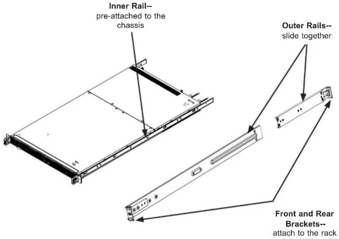
Figure 2-1. Identifying the Sections of the Rack Rails
text_image
Inner Rail-- pre-attached to the chassis Outer Rails-- slide together Front and Rear Brackets-- attach to the rack
Warning: do not pick up the server with the front handles. They are designed to pull the system from a rack only.
Assembling the Outer Rails
Each outer rail comes in two sections that must be assembled before mounting onto the rack.
Assembling the Outer Rails
- Identify the left and right outer rails by examining the ends, which bend outward. Match the left front outer rail with the left rear outer rail and the same for the right rails.
- Align the round post in the rear rail (B) with the round hole at the end of the slot in the front rail (A), and slide the front section into the rear section.
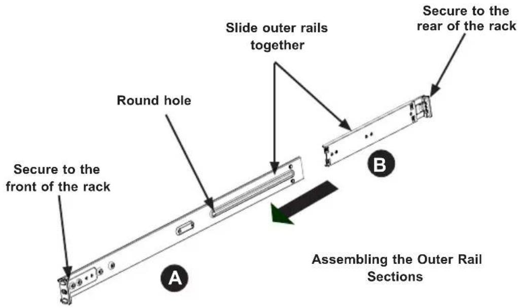
text_image
Round hole Secure to the front of the rack Slide outer rails together Secure to the rear of the rack Assembling the Outer Rail Sections A B
text_image
Outer rail assembled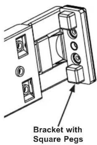
text_image
Bracket with Square PegsFigure 2-2. Assembling the Outer Rails

Slide rail mounted equipment is not to be used as a shelf or a work space.
Installing the Outer Rails onto the Rack
Each end of the assembled outer rail includes a bracket with square pegs to fit into your rack holes. If you have an older rack with round holes, these brackets must be removed, and you must use screws to secure the rail to the rack.
Outer Rail Installation
- Align the square pegs on the front end of the rail with the square holes on the front of the rack (C). Push the rail into the rack until the quick release bracket snaps into place, securing the rail to the rack. Keep the rail horizontal.
- Adjust the rail to reach just past the full depth of your rack.
- Align the square pegs on the rear end of the rail to the holes on the rack (D) and push the rail into the rack until the quick release bracket snaps into place, securing the rail to the rack.
- Repeat the procedure for the other outer rail assembly.
Figure 2-3. Installing the Outer Rails to the Rack
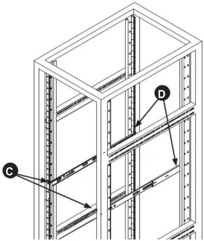
text_image
Technical diagram of a server rack structure with labeled components C and D
Stability hazard. The rack stabilizing mechanism must be in place, or the rack must be bolted to the floor before you slide the unit out for servicing. Failure to stabilize the rack can cause the rack to tip over.
Sliding the Chassis onto the Rack
Installing the Chassis into a Rack
- Align the chassis rails with the front of the rack rails.
- Slide the chassis rails into the rack rails, keeping the pressure even on both sides. The spring latch engages when the chassis is part way in. Push the server completely into the rack.
- (Optional) Insert and tighten the thumbscrews that hold the front of the server to the rack.
Figure 2-4. Installing the Server into a Rack

natural_image
Isometric line drawing of a multi-level server rack cabinet with visible structural ribs and a green arrow indicating a component (no text or symbols)Note: The figure above is for illustrative purposes only. Always install servers at the bottom of the rack first.
Notes
Chapter 3
System Interface
3-1 Overview
The control panel includes LEDs keep you constantly informed of the overall status of the system. There are also two buttons on the chassis control panel.
Figure 3-1. Control Panel

text_image
RESET UID3-2 Control Panel Buttons
There are two buttons located on the front of the chassis: a reset button and a power on/off button.

Power
The main power switch is used to apply or remove power from the power supply to the server. Turning off system power with this button removes the main power but maintains standby power. To perform many maintenance tasks, you must unplug system before servicing.
RESET

Reset
The reset button is used to reboot the system.
3-3 Control Panel LEDs
There are three LEDs that provide status information about the system.

UID LED
The universal identifier (UID) blue LED is activated from the motherboard. It is used to locate the server in large racks and server banks.

NIC
Indicates network activity when flashing.

HDD
When flashing, this LED indicates activity on the hard drives controlled by the on-chip SATA controller.
3-4 Power Supply LEDs
An LED on the rear of the power supply module displays the power status.
• Solid Green: When illuminated, indicates that the power supply is on.
- Solid Amber: When illuminated, indicates the power supply is plugged in and turned off, or the system is off but in an abnormal state.
- Blinking Amber: When blinking, it indicates that the system power supply temperature has reached 63^ C. The system will automatically power-down when the power supply temperature reaches 70^ C and restarts when the power supply temperature goes below 60^ C.
Notes
Chapter 4
Standardized Warning Statements for AC Systems
4-1 About Standardized Warning Statements
The following statements are industry standard warnings, provided to warn the user of situations which have the potential for bodily injury. Should you have questions or experience difficulty, contact Supermicro's Technical Support department for assistance. Only certified technicians should attempt to install or configure components.
Read this appendix in its entirety before installing or configuring components in the Supermicro chassis.
These warnings may also be found on our web site at http://www.supermicro.com/about/policies/safety_information.cfm.
Warning Definition

Warning!
This warning symbol means danger. You are in a situation that could cause bodily injury. Before you work on any equipment, be aware of the hazards involved with electrical circuitry and be familiar with standard practices for preventing accidents.
警告の定義
この警告サインは危険を意味します。
Installation Instructions

Warning!
Read the installation instructions before connecting the system to the power source. 設置手順書
This product relies on the building's installation for short-circuit (overcurrent) protection. Ensure that the protective device is rated not greater than: 250 V, 20 A.
サーキット・ブレーカー
Power Disconnection Warning

Warning!
The system must be disconnected from all sources of power and the power cord removed from the power supply module(s) before accessing the chassis interior to install or remove system components.
電源切断の警告
Equipment Installation

Warning!
Only trained and qualified personnel should be allowed to install, replace, or service this equipment.
機器の設置
This unit is intended for installation in restricted access areas. A restricted access area can be accessed only through the use of a special tool, lock and key, or other means of security. (This warning does not apply to workstations).
アクセス制限区域
There is the danger of explosion if the battery is replaced incorrectly. Replace the battery only with the same or equivalent type recommended by the manufacturer.
Dispose of used batteries according to the manufacturer's instructions
電池の取り扱い
Redundant Power Supplies

Warning!
This unit might have more than one power supply connection. All connections must be removed to de-energize the unit.
冗長電源装置
Hazardous voltage or energy is present on the backplane when the system is operating. Use caution when servicing.
バックプレーンの電圧
Comply with Local and National Electrical Codes

Warning!
Installation of the equipment must comply with local and national electrical codes.
地方および国の電気規格に準拠
Ultimate disposal of this product should be handled according to all national laws and regulations.
製品の廃棄
The fans might still be turning when you remove the fan assembly from the chassis.
Keep fingers, screwdrivers, and other objects away from the openings in the fan assembly's housing.
ファン・ホットスワップの警告
Power Cable and AC Adapter

Warning!
When installing the product, use the provided or designated connection cables, power cables and AC adaptors. Using any other cables and adaptors could cause a malfunction or a fire. Electrical Appliance and Material Safety Law prohibits the use of UL or CSA-certified cables (that have UL/CSA shown on the code) for any other electrical devices than products designated by Supermicro only.
電源コードとACアダプター
This chapter describes the X10SDV-2C-7TP4F/X10SDV-4C-7TP4F/X10SDV-7TP4F motherboard including how to connect the data and power cables and install add-on cards. All motherboard jumpers and connections are described and a layout and quick reference chart are included in this chapter. Remember to close the chassis completely when you have finished working on the motherboard to protect and cool the system sufficiently.
5-1 Handling the Motherboard
Static electrical discharge can damage electronic components. To prevent damage to printed circuit boards, it is important to handle them very carefully (see Chapter 4). Also note that the size and weight of the motherboard can cause it to bend if handled improperly, which may result in damage. To prevent the motherboard from bending, keep one hand under the center of the board to support it when handling.
The following measures are generally sufficient to protect your equipment from static discharge.
Precautions
- Use a grounded wrist strap designed to prevent static discharge.
- Touch a grounded metal object before removing any board from its antistatic bag.
- Handle a board by its edges only; do not touch its components, peripheral chips, memory modules or gold contacts.
- When handling chips or modules, avoid touching their pins.
- Put the motherboard, add-on cards and peripherals back into their antistatic bags when not in use.
5-2 Connecting Cables
The cables include the data cables for the peripherals and control panel and the power cables.
Connecting Data Cables
The cables used to transfer data from the peripheral devices have been carefully routed in preconfigured systems to prevent them from blocking the flow of cooling air that moves through the system from front to back.
If you need to disconnect any of these cables, you should take care to reroute them as they were originally after reconnecting them (be aware of the pin 1 locations). If you are configuring the system, keep the airflow in mind when routing the cables.
Connecting Power Cables
The X10SDV-2C-7TP4F/X10SDV-4C-7TP4F/X10SDV-7TP4F has a 24-pin primary power supply connector designated "JPW1" for connection to the ATX power supply. Connect the appropriate connector from the power supply to JPW1 to supply power to the motherboard. See the Connector Definitions section in this chapter for power connector pin definitions.
In addition, the JPH1 connector (to supply power for HDDs) and the JPV1 connector (to provide alternate power when JPW1 is not being used) may need to be connected to the power supply.
Connecting the Control Panel
JF1 contains header pins for various front control panel connectors. See Figure 5-1 for the pin locations of the various front control panel buttons and LED indicators. Please note that even and odd numbered pins are on opposite sides of each header. All JF1 wires have been bundled into single keyed ribbon cable to simplify their connection. Connect one end of this cable to JF1 and the other end to the Control Panel printed circuit board, located just behind the system status LEDs in the chassis.
See the Connector Definitions section in this chapter for details and pin descriptions of JF1.
Figure 5-1. Front Control Panel Header Pins (JF1)
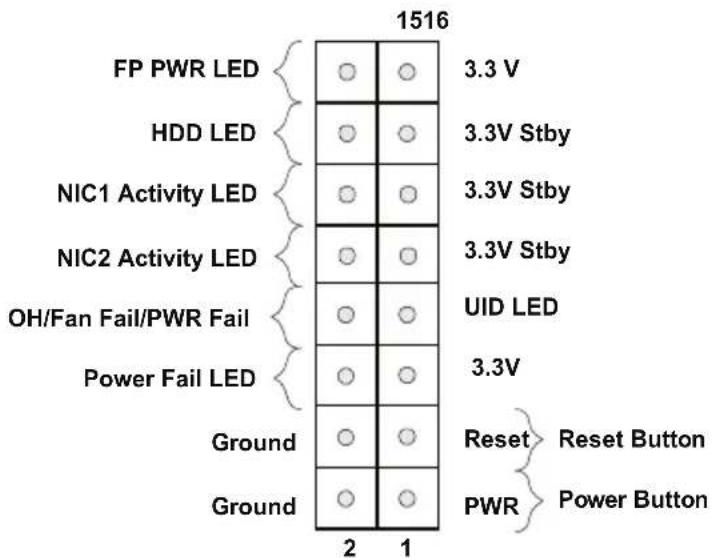
text_image
1516 FP PWR LED HDD LED NIC1 Activity LED NIC2 Activity LED OH/Fan Fail/PWR Fail Power Fail LED Ground Ground 3.3 V 3.3V Stby 3.3V Stby 3.3V Stby UID LED 3.3V Reset Reset Button PWR Power Button 2 15-3 I/O Ports
See Figure 5-2 below for the descriptions of the various rear I/O ports.
Figure 5-2. Rear Panel I/O Ports
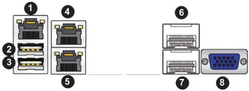
text_image
Diagram showing eight labeled network device connectors, including Ethernet, USB, and VGA ports with numbered labels.| Rear Panel I/O Ports | |
| 1. IPMI LAN Port 4.LAN Port 2 7. LAN Port 7 | |
| 2. USB Port 1 (USB 3.0) 5. LAN Port 1 8. VGA Port | |
| 3. USB Port 0 (USB 3.0) 6. LAN Port 8 | |
5-4 Installing Memory
Note: Check the Supermicro website for recommended memory modules.
CAUTION
Exercise extreme care when installing or removing DIMM modules to prevent any possible damage.
Installing DIMMs
- Insert the desired number of DIMMs into the memory slots, starting with slots DIMMA1. Pay attention to the notch along the bottom of the module to prevent inserting the DIMM module incorrectly. See Figure 5-3.
- Gently press down on the DIMM module until it snaps into place in the slot. Repeat step 1 to install to DIMM1B if needed.
Memory Support
The X10SDV-2C-7TP4F/X10SDV-4C-7TP4F/X10SDV-7TP4F has four DIMM sockets that can support up to 128 GB of ECC RDIMM (Registered DIMMs) or 64 GB of ECC/non-ECC UDIMM (Unregistered DIMMs) DDR4-2133/1866/1600 memory.
For the latest memory updates, please refer to our website. Please follow the tables below for correct installation.
Memory Installation Guidelines
When installing memory modules, the DIMM slots should be populated in the following order: DIMMA1, DIMMB1, then DIMMA2, DIMMB2.
- Always use DDR4 DIMM modules of the same size, type and speed. Mixing memory modules of different types and speeds is not allowed.
- The motherboard will support one DIMM module installed. However, for best memory performance, install DIMM modules in pairs.
Figure 5-3. DIMM Installation
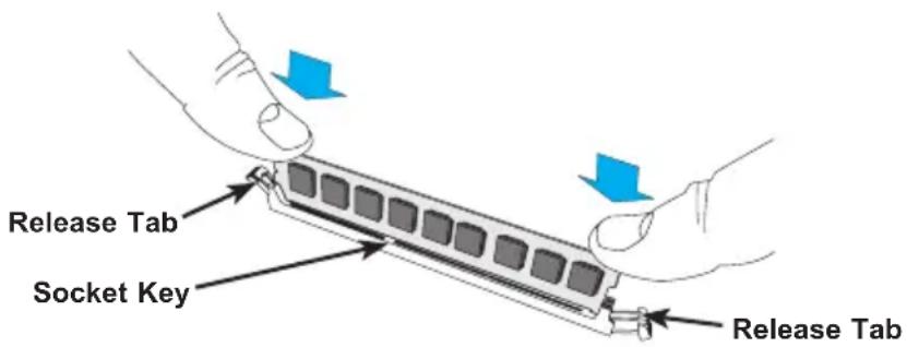
text_image
Release Tab Socket Key Release Tab| Recommended Population (Balanced) | ||||
| DIMMA1 Slot DIM | MMB1 Slot DIMM | A2 Slot DIMMB2 | Slot Total System | Memory |
| 4GB 4GB 8GB | ||||
| 4GB 4GB 4GB 4GB 16GB | ||||
| 8GB 8GB 16GB | ||||
| 8GB 8GB 8GB 8GB 32GB | ||||
| 16GB 16GB 32GB | ||||
| 16GB 16GB 16GB 16GB | 64GB | |||
| 32GB 32GB 64GB | ||||
| 32GB 32GB 32GB 32GB 32GB | 128GB | |||
5-5 Adding PCI Expansion Cards
PCI Expansion Slots
One RSC-RR1U-E8 riser card is used to support a FHHL (full-height, half-length) expansion (add-on) card to the system.
PCI Card Installation
Before installing a PCI add-on card, make sure it is supported by the riser card. Begin by releasing the locking tab that corresponds to the slot you wish to populate. Insert the expansion card into the riser card by pushing down with your thumbs evenly on both sides of the card.
PCI Slot/Card Configurations
Riser Card
RSC-RR1U-E8 (pre-installed)
Expansion Card Supported
1x PCI-E 3.0 x8 FHHL card
5-6 Motherboard Details
Figure 5-4. SUPER X10SDV Series Layout

text_image
LAN7/8 JPL3 LAN5/6 LAN3/4 LAN1/2 IPMI LAN MP-SRW1 LED8 LED7 VGA UID BAR CODE MP-SRW2 JIPMB1 JPB1 JSMB1 JI2C1 JI2C2 JPG1 COM1 JPS1 JBR1 JWD1 JL1 JOH1 USB5/6 I-SATA3 USB3/4 I-SATA2 JPM1 Slot6 Slot7 M2-SRW2 JPNI2C1 JPTG1 JPL2 JPME2 M2-SRW1 JLANLED1 JMTGLED1 JMD1: M.2 Intel Xeon D-1500 SoC LEDS1 JD1 I-SATA0 JTPM1 JBT1 LED3 BT1 FANB FANA L-SAS8-11 L-SAS12-15 L-SAS4-7 L-SAS0-3 JSD2 JSD1 JPME1 JF1 USB2 FAN4 USB2 FAN4 JGP1 FAN2 FAN3 I-SGPIO1 JPH1 FAN1 JSTBY1| X10SDV Flex Series Model Variations | |||
| Model | X10SDV-7TP4F | X10SDV-4C-7TP4F | X10SDV-2C-7TP4F |
| CPU | Xeon D-1537 | Xeon D-1518 | Xeon D-1508 |
| # of Cores | 8 | 4 | 2 |
| Cache | 12 MB | 6 MB | 3 MB |
| CPU Base Frequency | 1.7 GHz | 2.2 GHz | 2.2 GHz |
| Intel Turbo Boost Frequency | 2.3 GHz | N/A | 2.6 GHz |
| SoC TDP | 35W | 35 W | 25 W |
| 16 SAS2/SATA3 Ports (LSI 2116) | Yes | Yes | Yes |
| Dual 1GbE LAN (i210) | Yes | Yes | Yes |
| Quad 10GbE LAN (i350-AM2) | No | No | No |
| Dual 10GbE LAN from SoC | Yes | Yes | Yes |
| CPU Heatsink with FAN | No | No | No |
X10SDV Series Quick Reference
Jumper Description Default Setting
| JBR1 | BIOS Recovery | Pins 1-2 (Normal) |
| JBT1 | CMOS Clear | See Section 5-8 |
| JI2C1/JI2C2 | SMB to PCI-Exp. Slots /Disable | Pins 2-3 (Disabled) |
| JPB1 | BMC Enable/Disable (Debug use only) | Pins 1-2 (Enabled) |
| JPG1 | VGA Enable/Disable | Pins 1-2 (Enabled) |
| JPL1 | LAN1 Enable/Disable | Pins 1-2 (Enabled) |
| JPL2 | LAN2 Enable/Disable | Pins 1-2 (Enabled) |
| JPL3 | LAN3/4/5/6 Enable/Disable | Pins 1-2 (Enabled) |
| JPME1 | ME Recovery | Pins 1-2 (Normal) |
| JPME2 | Manufacturing Mode | Pins 1-2 (Normal) |
| JPS1 | SAS 2.0 Enable/Disable Pins 1-2 (Enabled) | |
| JPTG1 | 10Gb Ethernet Enable/Disable | Pins 1-2 (Enabled) |
| JPUSB1 | USB Wakeup (USB0/1) Enable/Disable | Pins 1-2 (Enabled) |
| JWD1 | Watch Dog | Pins 1-2 (Reset) |
Connector Description
| COM1 COM1 Header | |
| FAN1 ~ FAN4 | CPU/System Cooling Fans |
| FANA, FANB | |
| IPMI LAN Dedicated IPMI LAN Port | |
| I-SATA0 ~ I-SATA5 | Intel SATA Ports (I-SATA0 / I-SATA1 support SuperDOM, I-SATA4 via M.2, I-SATA5 via Mini-PCIE mSATA) |
| I-SGPIO1 Serial Link General Purpose I/O Header | |
| JD1 Speaker (Pins 1-3: Power LED, Pins 4-7: Speaker) | |
| JF1 Front Panel Control Header | |
| JGP1 General Purpose I/O Header | |
| JIPMB1 4-pin External SMbus I | ^2C Header (for an IPMI Card) |
| JL1 Chassis Intrusion Header | |
| JLANLED1 LAN3 ~ LAN6 Activity LED Header | |
| JMD1 M.2 PCI-E 3.0 X4 / I-SATA4 Slot | |
| JMP1 Mini PCI-E 2.0 X1 / I-SATA5 Slot | |
| JNVI ^2 C1 NVMe I | ^2C Header |
Table continued on next page.
Connector Description
| JOH1 Overheat LED Header | |
| JPH1 4-pin Power Connector for HDDs | |
| JPI^2C1 Power Supply SMBus I | ^2C Header |
| JPV1 12V 8-pin Power Connector (provides alternate power for special enclosure when the 24-pin ATX power is not in use) | |
| JPW1 24-pin ATX Power Connector | |
| JSD1, JSD2 SATA DOM (Device On Module) Power Connectors | |
| JSMB1 SMBus Header | |
| JSTBY1 5V Standby Power Header | |
| JTGLED1 LAN7 ~ LAN8 Activity LED Header | |
| JTPM1 Trusted Platform Module (TPM)/Port 80 Connector | |
| LAN1, LAN2, LAN7, | Gigabit Ethernet (RJ45) Ports (LAN1 ~ LAN2) |
| LAN8 | 10Gigabit Ethernet (SFP+) Ports (LAN7 ~ LAN8) |
| L-SAS0 ~ L-SAS15 SAS 2.0 Ports | |
| M2-SRW1 ~ SRW3 M.2 Mounting Screws | |
| MP-SRW1 ~ SRW2 PCI-E 2.0 x1 / I-SATA5 Slot Mounting Screws | |
| Slot6, Slot7 | CPU PCI-E 3.0 x8 Slot |
| UID | Unit ID Button |
| USB 0/1 | Back Panel USB 3.0 Ports |
| USB 2 | USB Type-A Connector |
| USB 3/4, 5/6 | Front Access USB 2.0 Ports |
| LED | Description | Color/State | Status |
| LED3 | Power LED | Green: On | System Power On |
| LED7 | UID Switch LED | Blue: On | Unit Identified |
| LED8 | Overheat/PWR Fail/Fan Fail LED | Red: Solid on Blinking | OverheatPWR Fail or Fan Fail |
| LEDM1 | BMC Heartbeat LED | Green: Blinking | BMC: Normal |
| LEDS1 | SAS Heartbeat LED | Green: BlinkingRed: Soild On | SAS ActiveSAS Error |
| LEDT1 | LAN7 Link Status | Green: On | LAN7 Normal |
| LEDT2 | LAN7 Activity | Green: Blinking | LAN7 Active |
| LEDT3 | LAN8 Link Status | Green: On | LAN8 Normal |
| LEDT4 | LAN8 Activity | Green: Blinking | LAN8 Active |
5-7 Connector Definitions
Power Connectors
The 24-pin ATX power connector at JPW1 is used to provide power to the motherboard. JPV1 is a 12V DC power connector that provides alternative power for special a enclosure when the 24-pin ATX power is not in use. The 4-pin HDD power connector JPH1 provides power to onboard HDD devices.
Note: Do not use the 8-pin DC power at JPV1 when the 24-pin ATX Power at JPW1 is connected to the power supply. Do not plug in both JPV1 and JPW1 at the same time.
| ATX Power 24-pin Connector Pin Definitions (JPW1) | |||
| Pin# | Definition | Pin # | Definition |
| 13 | +3.3V 1 +3.3V | ||
| 14 | -12V 2 +3.3V | ||
| 15 | COM 3 COM | ||
| 16 | PS_ON 4 +5V | ||
| 17 | COM 5 COM | ||
| 18 | COM 6 +5V | ||
| 19 | COM 7 COM | ||
| 20 | Res (NC) 8 PWR_OK | ||
| 21 | +5V 9 5VSB | ||
| 22 | +5V 10 +12V | ||
| 23 | +5V 11 +12V | ||
| 24 | COM 12 +3.3V | ||
| 8-pin DC PowerPin Definitions (JPV1) | |
| Pin# | Definition |
| 1-4 GND | |
| 5-8 12V | |
| 4-Pin HDD Power Pin Definitions (JPH1) | |
| Pin# | Definition |
| 1 12V | |
| 2-3 GND | |
| 4 | 5V |
Power LED
The Power LED connection is located on pins 15 and 16 of JF1. Refer to the table on the right for pin definitions.
| Power LEDPin Definitions (JF1) | |
| Pin# | Definition |
| 15 3.3V | |
| 16 PWR LED | |
HDD LED
The HDD LED connection is located on pins 13 and 14 of JF1. Attach a cable here to indicate the status of all HDD-related activities. See the table on the right for pin definitions.
| HDD LEDPin Definitions (JF1) | |
| Pin# | Definition |
| 13 3.3V Standby | |
| 14 HD LED | |
The NIC (Network Interface Controller) LED connection for LAN port 2 is located on pins 9 and 10 of JF1, and the LED connection for LAN port 1 is on pins 11 and 12. Attach NIC LED cables to their respective pins to display network activity. Refer to the table on the right for pin definitions.
| LAN1/LAN2 LEDPin Definitions (JF1) | |
| Pin# | Definition |
| 9-11 | 3.8V Standby |
| 10-12 | NIC Activity LED |
Overheat (OH)/Fan Fail/PWR Fail/ UID LED
Connect an LED cable to pins 7 and 8 of JF1 for Overheat/Fan Fail/Power Fail and UID LED indications. The blue LED on pin 7 works as the front panel UID LED indicator. The red LED on pin 8 works provides warnings of overheat, fan failure or power failure. The red LED takes precedence over the blue LED by default. Refer to the table on the right for pin definitions.
| OH/Fan Fail/PWR Fail/Blue UID LED Pin Definitions (JF1) | |
| Pin# | Definition |
| 7 Blue | UID LED |
| 8 OH/Fan Fail/Power Fail Cathode | |
Reset Button
The Reset Button connection is located on pins 3 and 4 of JF1. Attach it to a hardware reset switch on the computer case to reset the system. Refer to the table on the right for pin definitions.
| Reset ButtonPin Definitions (JF1) | |
| Pin# | Definition |
| 3 Reset | |
| 4 Ground | |
Power Fail LED
The Power Fail LED connection is located on pins 5 and 6. Refer to the table on the right for pin definitions.
| Power FailPin Definitions (JF1) | |
| Pin# | Definition |
| 5 3.3V | |
| 6 Power Fail | |
Power Button
The Power Button connection is located on pins 1 and 2 of JF1. Momentarily contacting both pins will power on/off the system. This button can be configured as 4 Seconds Override or Instant Off (with a setting in the BIOS setting, see Chapter 7). Refer to the table on the right for pin definitions.
Universal Serial Bus (USB)
Two USB 3.0 ports (USB0/1) are located on the I/O back panel. Two USB 2.0 headers (USB3/4 and USB5/6) and one USB Type-A header are also provided on the motherboard to provide front panel access. USB cables are not included. Refer to the tables on the right for pin definitions.
| Power ButtonPin Definitions (JF1) | |
| Pin# | Definition |
| 1 Signal | |
| 2 Ground | |
| Back Panel USB 3.0Pin Definitions | |
| Pin # Definition Pin # Definition | |
| 1 +5V 5 +5V | |
| 2 USB_PN1 6 USB_PN0 | |
| 3 USB_PP1 7 USB_PP0 | |
| 4 Ground 8 Ground | |
| Internal USB Port 2.0Pin Definitions | |
| Pin # Definition Pin # Definition | |
| 1 +5V 2 +5V | |
| 3 USB_PN2 4 USB_PN3 | |
| 5 USB_PP2 6 USB_PP3 | |
| 7 Ground 8 Ground | |
| 9 Key 10 NC | |
Gigabit Ethernet LAN Ports
Two Gigabit Ethernet ports (LAN1 and LAN2) and a dedicated IPMI LAN port are located on the rear I/O panel to provide network connections. These ports accept RJ45 type cables. Please refer to the LED Indicator Section for LAN LED information.
10G SFP+/Ethernet LAN Ports
Two 10 Gigabit SFP+ (Small-form Factor Pluggable) Ethernet LAN ports, supported by the SoC, are located at LAN7 and LAN8 on the rear I/O panel. Please refer to the 10G LAN LED section for 10G LAN LED information.
Serial Port
A COM port is on the motherboard to provide a front accessible serial connection.
Unit Identifier Switch
A Unit Identifier (UID) switch and two LED indicators are located on the motherboard. The UID switch is located next to the VGA port on the back panel. The rear UID LED (LED7) is located next to the UID switch. The Front Panel UID LED is located at pin 7 of the Front Control Panel at JF1. Connect a cable to pin 7 on JF1 for Front Panel UID LED indication. When you press the UID switch, both the rear UID LED and the Front Panel UID LED Indicators will be turned on. Press the UID switch again to turn off both LED Indicators. These UID Indicators provide easy identification of a system unit that may be in need of service.
Note: UID can also be triggered via IPMI on the motherboard. For more information on IPMI, please refer to the IPMI User's Guide posted on our website at http://www.supermicro.com.
Fan Headers
This motherboard has six 4-pin fan headers. Although pins 1-3 of the fan headers are backward compatible with the traditional 3-pin fans, we recommend you use 4-pin fans to take advantage of the fan speed control via Pulse Width Modulation through the BMC. This allows the fan speeds to be automatically adjusted based on the motherboard temperature.
Chassis Intrusion
A Chassis Intrusion header is located at JL1 on the motherboard. Attach the appropriate cable from the header to the chassis to inform you of an intrusion when the chassis is opened.
Internal Speaker
The Internal Speaker, located at SP1, can be used to provide audible indications for various beep codes. See the table on the right for pin definitions.
| UID Switch | |
| Pin# | Definition |
| 1 Ground | |
| 2 Ground | |
| 3 Button In | |
| 4 Button In | |
| UID LEDStatus | |
| Color/State Status | |
| Blue: On Unit Identified |
| Fan HeaderPin Definitions | |
| Pin# | Definition |
| 1 Ground (Black) | |
| 2 12V (Red) | |
| 3 Tachometer | |
| 4 PWM_Control | |
| Chassis Intrusion Pin Definitions (JL1) | |
| Pin# | Definition |
| 1 Ground | |
| 2 Intrusion Input | |
| Internal Buzzer (SP1) Pin Definition | ||
| Pin# | Definitions | |
| 1 Pos. (+) Beep In | ||
| 2 Neg. (-) Alarm | Speaker | |
TPM Header/Port 80 Header
A Trusted Platform Module/Port 80 header, located at JTPM1, provides Trusted Platform (TPM) support and Port 80 connection. Use this header to enhance system performance and data security. See the table on the right for pin definitions.
Note: Please go to the following link for more information on TPM: http://www.supermicro.com/manuals/other/TPM.pdf
| TPM/Port 80 HeaderPin Definitions | |
| Pin # Definition Pin # Definition | |
| 1 LCLK 2 GND | |
| 3 LFRAME# 4 < (KEY)> | |
| 5 LRESET# 6 +5V (X) | |
| 7 LAD 3 8 LAD 2 | |
| 9 +3.3V 10 LAD1 | |
| 11 LAD0 12 GND | |
| 13 SMB_CLK4 14 SMB_DAT4 | |
| 15 +3V_DUAL 16 SER RQ | |
| 17 GND 18 CLKRUN# (X) | |
| 19 LPCPD# 20 LDRQ# (X) | |
4-pin External I²C BMC Header
A System Management Bus header for IPMI 2.0 is located at JIPMB1. Connect the appropriate cable here to use the IPMI I²C connection on your system.
| External I2C Header Pin Definitions | |
| Pin# | Definition |
| 1 Data | |
| 2 Ground | |
| 3 Clock | |
| 4 No Connection | |
DOM PWR Connector
The Disk-On-Module (DOM) power connectors, located at JSD1 and JSD2, provide 5V power to a solid state DOM storage device connected to the SATA port. See the table on the right for pin definitions.
| DOM PWRPin Definitions | |
| Pin# | Definition |
| 1 | 5V |
| 2 Ground | |
| 3 Ground | |
Overheat LED Header
The JOH1 header is used to connect an LED indicator to provide warnings of chassis overheating Refer to the tables on the right for pin definitions.
| Overheat LED Pin Definitions | |
| State | Definition |
| 1 | 3.3V |
| 2 | OH Active |
| OH Status (Red LED) | |
| State | Definition |
| Off | Normal |
| Solid Overheat | |
Speaker
On the JD1 header, pins 1-3 are used for the Power LED and pins 4-7 are used for the speaker. See the table on the right for pin definitions.
| Speaker Connector Pin Definitions | |
| Pin# | Definition |
| 1-3 Power | LED |
| 4-7 Speaker | |
Standby Power
The Standby Power header is located at JSTBY1 on the motherboard. See the table on the right for pin definitions.
| Standby PowerPin Definitions | |
| Pin# | Definition |
| 1 +5V Standby | |
| 2 Ground | |
| 3 No connection | |
Serial Link I/O Header
The Serial Link General Purpose Input/Output (SGPIO) header is used to communicate with the enclosure management chip in the system. See the table on the right for pin definitions.
| Serial Link I/O HeaderPin Definitions | |||
| Pin# | Definition | Pin | Definition |
| 1 NC | 2 NC | ||
| 3 Ground 4 DATA Out | |||
| 5 Load 6 Ground | |||
| 7 Clock 8 NC | |||
System Management Bus Header
The System Management Bus header for additional slave devices or sensors is located as JSMB1. Refer to the table on the right for pin definitions.
| SMBus PowerPin Definitions | |
| Pin# | Definition |
| 1 Data | |
| 2 Ground | |
| 3 Clock | |
Power SMB (I²C) Header
The Power System Management Bus header at JPI ^2 C1 monitors the power supply, fan and system temperature. Refer to the table on the right for pin definitions.
| Standby Power Pin Definitions | |
| Pin# | Definition |
| 1 +5V Standby | |
| 2 Ground | |
| 3 No connection | |
NVMe I²C Header
Connector JNVI ^2 C is a management header for the Supermicro AOC NVMe PCI-E peripheral cards. Please connect the I ^2 C cable to this connector.
General Purpose I/O Header
JGP1 is a general purpose I/O header. See the table on the right for pin definitions.
| GPIO HeaderPin Definitions | |||
| Pin# | Definition | Pin | Definition |
| 1 P3V | 3 2 GND | ||
| 3 GP0 | 4 GP1 | ||
| 5 GP2 | 6 GP3 | ||
| 7 GP4 | 8 GP5 | ||
| 9 GP6 | 10 GP7 | ||
| GPIO Register Address Table To Control JGPIO Pin Header | ||||
| JGPIO1 PIN# SoC GPIO# USE Select IO Select Level | ||||
| 1 Power | ||||
| 2 Ground | ||||
| 3 17 IO 0x500 [17] IO 0x504 [17] IO 0x50C [17] | ||||
| 4 | 68 | IO 0x540 [4] | IO 0x544 [4] | IO 0x548 [4] |
| 5 | 01 | IO 0x500 [1] | IO 0x504 [1] | IO 0x50C [1] |
| 6 | 69 | IO 0x540 [5] | IO 0x544 [5] | IO 0x548 [5] |
| 7 | 06 | IO 0x500 [6] | IO x0504 [6] | IO 0x50C [6] |
| 8 | 70 | IO 0x540 [6] | IO 0x544 [6] | IO 0x548 [6] |
| 9 | 07 | IO 0x500 [7] | IO 0x504 [7] | IO 0x50C [7] |
| 10 | 71 | IO 0x540 [7] | IO 0x544 [7] | IO 0x548 [7] |
Note: Please refer to the Intel Xeon Processor D-1500 Product Family Datasheet for more information.
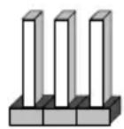
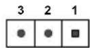
5-8 Jumper Settings
Explanation of Jumpers
To modify the operation of the motherboard, jumpers can be used to choose between optional settings. Jumpers create shorts between two pins to change the function of the connector. Pin 1 is identified with a square solder pad on the printed circuit board. See the diagram at right for an example of jumping pins 1 and 2. Refer to the motherboard layout page for jumper locations.
Note: On two-pin jumpers, "Closed" means the jumper is on and "Open" means the jumper is off the pins.
Connector
Pins

Jumper
Setting
CMOS Clear
JBT1 is used to clear CMOS and will also clear any passwords. Instead of pins, this jumper consists of contact pads to prevent accidentally clearing the contents of CMOS.
To Clear CMOS
- First power down the system and unplug the power cord(s).
- With the power disconnected, short the CMOS pads with a metal object such as a small screwdriver.
- Remove the screwdriver (or shorting device).
- Reconnect the power cord(s) and power on the system.
Note: Do not use the PW_ON connector to clear CMOS.
VGA Enable/Disable
JPG1 allows you to enable or disable the VGA port. The default position is on pins 1 and 2 to enable VGA. See the table on the right for jumper settings.
| VGA Enable/Disable Jumper Settings (JPG1) | |
| Jumper Setting | Definition |
| Pins 1-2 Enabled | |
| Pins 2-3 Disabled | |
PCI-E Slot SMB Enable (I²C1/I²C2)
Use jumpers I^2C1/I^2C2 to enable PCI SMB (System Management Bus) support to improve system management for the onboard PCI-E slot. See the table on the right for jumper settings.
| PCI Slot SMB EnableJumper Settings | |
| Pin# | Definition |
| Pins 1-2 Enabled | |
| Pins 2-3 Disabled (Default) | |
Watch Dog Timer Enable
Watch Dog is a system monitor that can reboot the system when a software application hangs. Close pins 1-2 to reset the system if an application hangs. Close pins 2-3 to generate a non-maskable interrupt signal for the application that hangs. See the table on the right for jumper settings. Watch Dog must also be enabled in the BIOS.
| Watch DogJumper Settings | |
| Pin# | Definition |
| Pins 1-2 Reset (Default) | |
| Pins 2-3 NMI | |
| Open LAN pairs set to defaultmode without resetor NMI | |
USB Wake-Up
Use the JPUSB1 jumper to enable the function of "System Wake-Up via USB devices" for USB0/1. This jumper allows you to "wake-up" the system by pressing a key on the USB keyboard or by clicking the USB mouse of your system. The JPUSB1 jumper is used together with the USB Wake-Up function in the BIOS. Enable both the jumper and the BIOS setting to enable this function. See the table on the right for jumper settings.
| USB Wake-upJumper Settings | |
| Pin# | Definition |
| Pins 1-2 | Enabled (Default) |
| Pins 2-3 | Disabled |
Management Engine (ME) Recovery
Use JPME1 to select ME Firmware Recovery mode, which will limit resource allocation for essential system operation only in order to maintain normal power operation and management. In the single operation mode, online upgrade will be available via Recovery mode. See the table on the right for jumper settings.
| ME RecoveryJumper Settings | |
| Pin# | Definition |
| Pins 1-2 | Normal (Default) |
| Pins 2-3 | ME Recovery |
BIOS Recovery
Close pins 2 and 3 of jumper JBR1 for BIOS recovery. The default setting is on pins 1 and 2 for normal operation. See the table on the right for jumper settings.
| BIOS RecoveryJumper Settings | |
| Pin# | Definition |
| Pins 1-2 | Normal |
| Pins 2-3 | BIOS Recovery |
BMC Enabled
JPB1 allows you to enable the BMC (Baseboard Management Control) chip and the onboard IPMI connection for debugging purpose only. After the BMC is disabled, IPMI health and remote management functions are no longer supported. See the table on the right for jumper settings.
Note: Please aways keep BMC enabled to make sure that the platform operates reliably with the health monitor.
| BMC EnabledJumper Settings | |
| Pin# | Definition |
| Pins 1-2 | Enabled (Default) |
| Pins 2-3 | Disabled |
GbE LAN Ports Enable/Disable
Jumpers JPL1 and JPL2 are used to enable or disable LAN ports 1 and 2, respectively. Use JPL3 to enable or disable LAN ports 3, 4, 5, and 6. See the table on the right for jumper settings.
| GbE LAN EnableJumper Settings | |
| Pin# | Definition |
| Pins 1-2 | Enabled (Default) |
| Pins 2-3 | Disabled |
10GbE LAN Ports Enable/Disable
JPTG1 is used to enable or disable 10GbE support. See the table on the right for jumper settings.
| 10Gb Enable/DisableJumper Settings | |
| Pin# | Definition |
| Pins 1-2 | Enabled (Default) |
| Pins 2-3 | Disabled |
SAS Port Enable/Disable
Use JPS1 to enable the onboard SAS ports. See the table on the right for jumper settings.
| SAS Port Enable/Disable Jumper Settings | |
| Pin# | Definition |
| Pins 1-2 | Enabled (Default) |
| Pins 2-3 | Disabled |
ME Manufacturing Mode
Close JPME2 to bypass SPI flash security and force the system to use the Manufacturing Mode, which will allow the user to flash the system firmware from a host server to modify system settings. See the table on the right for jumper settings.
| Manufacturing ModeJumper Settings | |
| Pin# | Definition |
| Pins 1-2 | Normal (Default) |
| Pins 2-3 | Manufacturing Mode |
5-9 Onboard Indicators
LAN Port LEDs
The Ethernet ports have two LEDs. On each port, one LED indicates activity when flashing while the other LED may be green, amber or off to indicate the speed of the connection. See the tables on the right for more information.
| LAN Port Link Speed LED | |
| Color | Definition |
| Off No | Connection or 10 Mbps |
| Amber 1 | Gbps |
| Green | 100Mps (10Gbps for 10GbE Port) |
| Overheat/PWR Fail/Fan Fail LED Settings | ||
| Color | Status | Definition |
| Off No Connection | ||
| Yellow Flashing Active | ||
BMC Heartbeat LED
A BMC Heartbeat LED is located at LEDM1. See the table on the right for more information.
| BMC Heartbeat LED Status | |
| Color/State | Definition |
| Green: Blinking BMC: Normal | |
Onboard Power LED
An onboard Power LED is located at LED3 on the motherboard. When this LED is on, the system is on. Be sure to turn off the system and unplug the power cord before removing or installing components. See the table on the right for more information.
| Onboard PWR LED IndicatorLED Settings | |
| Color | Definition |
| Off System | Off (PWR cable not connected) |
| Green System On | |
Overheat/PWR Fail/Fan Fail LED
An onboard Overheat/PWR Fail/Fan Fail LED is located at LED8. See the table on the right for more information.
| Overheat/PWR Fail/Fan Fail LED Settings | |
| Color | Definition |
| Solid Overheat | |
| Blinking Power Fail or Fan Fail | |
Unit Identification LED
A rear UID LED indicator (LED7) is located next to the Unit Identifier (UID) switch on the I/O back panel. The front panel UID LED is located at pin 7 of the Front Control Panel at JF1. Connect a cable to pin 7 on JF1 for front panel UID LED indication. When you press the UID switch, both rear UID LED and front panel UID LED Indicators will be turned on. Press the UID switch again to turn off both LED Indicators. These UID Indicators provide easy identification of a system unit that may be in need of service.
Note: UID can also be triggered via IPMI on the motherboard. For more information on IPMI, please refer to the IPMI User's Guide posted on our website at http://www.supermicro.com.
| UID LEDStatus | |
| Color/State | Status |
| Blue: On Unit | Identified |
10G LAN Activity LED
The 10G LAN Activity LED for LAN7 is located at LEDT2, and the 10G LAN LED Activity LED for LAN8 is located at LEDT4. When the LEDs are blinking, LAN7/LAN8 are active. See the table on the right for the colors and definitions.
| 10G LAN ActivityLED Indicator | |
| Color/State | Definition |
| LEDT2Green: Blinking | LAN7 Active |
| LEDT4Green: Blinking | LAN8 Active |
10G LAN Link Status LED
The 10G LAN Link status LED for LAN7 is located at LEDT1, and the 10G LAN Link status LED for LAN8 is located at LEDT3. When the LEDs are on, LAN7/LAN8 are working properly. See the table on the right for the colors and definitions.
| 10G LAN Link StatusLED Indicator | |
| Color/State | Definition |
| LEDT1Green: On | LAN7 Normal |
| LEDT3Green: On | LAN8 Normal |
SAS Activity LED
A SAS heartbeat LED is located at LEDS1. When LEDS1 flahsed, it indicates activity on a SAS port. See the table on the right for more information.
| SAS ActivityLED Indicator | |
| Color | Definition |
| Green:Blinking | SAS Active |
| Red SAS Error | |
5-10 SATA/SAS Ports
SATA Ports
This motherboard has six SATA 3.0 ports. I-SATA0 and I-SATA1 have built-in power pins to support Supermicro's SATA DOM (Disk On Module) solutions. I-SATA4 is via the JMD1 M.2 connector, I-SATA5 is via the JMP1 Mini PCI-E slot.
SAS Ports
Sixteen SAS 2.0 ports are provided at JSAS1 \~ JSAS4 on the motherboard via four Mini-SAS HD cables. These SAS ports are supported by the LSI2116 SAS controller.
5-11 Installing Drivers
The Supermicro FTP site contains drivers and utilities for your system at ftp://ftp.supermicro.com. Some of these must be installed, such as the chipset driver.
After accessing the FTP site, go into the CDR_Images directory and locate the ISO file for your motherboard. Download this file to create a CD/DVD of the drivers and utilities it contains. (You may also use a utility to extract the ISO file if preferred.)
Another option is to go to the Supermicro website at http://www.supermicro.com/products/. Find the product page for your motherboard here, where you may download individual drivers and utilities.
After creating a CD/DVD with the ISO files, insert the disk into the CD/DVD drive on your system and the display shown in Figure 5-5 should appear.
Figure 5-5. Driver Installation Display Screen

text_image
SUPERMICRO X10SDV-7TP8F Motherboard Drivers & Tools (Win7) SUPERMICRO® Drivers & Tools Intel D-1500 Chipset X10SDV-7TP8F/ 7TP4F/TP8F SUPERMICRO Computer Inc. Intel Chipset INF files Microsoft .Net Framework (Optional) ASPEED Graphics Driver Intel Rapid Storage Technology Enterprise Intel USB 3.0 Drivers X557 10G Driver Intel PRO Network Connections Drivers Intel Management Engine SUPERMICRO SuperDoctor 5 Build driver disketes and manuals Browse CD Auto Start Up Next Time For more information, please visit SUPERMICRO's web site.Note: Click the icons showing a hand writing on paper to view the readme files for each item. Click the computer icons to the right of these items to install each item (from top to the bottom) one at a time. After installing each item, you must re-boot the system before moving on to the next item on the list. The bottom icon with a CD on it allows you to view the entire contents.
SuperDoctor® 5
The Supermicro SuperDoctor 5 is a program that functions in a command-line or web-based interface in Windows and Linux operating systems. The program monitors system health information such as CPU temperature, system voltages, system power consumption, fan speed, and provides alerts via email or Simple Network Management Protocol (SNMP).
SuperDoctor 5 comes in local and remote management versions and can be used with Nagios to maximize your system monitoring needs. With SuperDoctor 5 Management Server (SSM Server), you can remotely control power on/off and reset chassis intrusion for multiple systems with SuperDoctor 5 or IPMI. SD5 Management Server monitors HTTP, FTP, and SMTP services to optimize the efficiency of your operation.
Note: The default User Name and Password for SuperDoctor 5 is admin / admin.
Figure 5-6. SuperDoctor 5 Interface Display Screen (Health Information)

text_image
SuperDoctor 5 Health Info SuperDoctor 5 Control panel Report Power Control Select Language: English [admin] Login Motherboard: X80 TU-LN4* Fan Speed FAN S FAN E Status Chassis here Voltage CVDI Value CVDI DIM -1.3 V +3 V +5VSB -22 V +1.1 V -3.1VCC -3.3VSB VBAT Temperature 33/91.4 89 60 40 20 9 189 87 43 29 9 213 443 125 84 42 130 80 40 20 0 126 48/104 40/105.6 310 88 60 43 29 8 214 468 120 108 88 48 28 8 216 41/105.6 318 88 60 48 28 8 218 42/107.6 PI StatusNote: The SuperDoctor 5 program and User's Manual can be downloaded from the Supermicro website at http://www.supermicro.com/products/nfo/sms_sd5.cfm.
5-13 Onboard Battery
Care must be taken to assure that the chassis cover is in place when the system is operating to assure proper cooling. Out of warranty damage to the system can occur if this practice is not strictly followed.
Figure 5-7. Installing the Onboard Battery
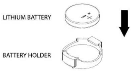
text_image
LITHIUM BATTERY BATTERY HOLDERPlease handle used batteries carefully. Do not damage the battery in any way; a damaged battery may release hazardous materials into the environment. Do not discard a used battery in the garbage or a public landfill. Please comply with the regulations set up by your local hazardous waste management agency to dispose of your used battery properly.
Chapter 6
Advanced Chassis Setup
This chapter covers the steps required to install components and perform maintenance on the SC801LTS-R406P chassis. For component installation, follow the steps in the order given to eliminate the most common problems encountered. If some steps are unnecessary, skip ahead to the step that follows.
Tools Required: The only tool you will need to install components and perform maintenance is a Philips screwdriver.
6-1 Static-Sensitive Devices
Electrostatic discharge (ESD) can damage electronic components. To prevent damage to any printed circuit boards (PCBs), it is important to handle them very carefully. The following measures are generally sufficient to protect your equipment from ESD damage.
Precautions
- Use a grounded wrist strap designed to prevent static discharge.
- Touch a grounded metal object before removing any board from its antistatic bag.
- Handle a board by its edges only; do not touch its components, peripheral chips, memory modules or gold contacts.
- When handling chips or modules, avoid touching their pins.
- Put the motherboard, add-on cards and peripherals back into their antistatic bags when not in use.
- For grounding purposes, make sure your computer chassis provides excellent conductivity between the power supply, the case, the mounting fasteners and the motherboard.
Unpacking
The motherboard is shipped in antistatic packaging to avoid static damage. When unpacking the board, make sure the person handling it is static protected.
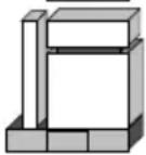
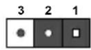
Figure 6-1. Front and Rear Chassis Views

text_image
Control PanelPower Supplies
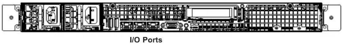
natural_image
Interior view of an I/O ports rack with visible circuitry and connectors (no text or symbols)6-2 Control Panel
The control panel (located on the front of the chassis) must be connected to the JF1 connector on the motherboard to provide you with system status indications. A ribbon cable has bundled these wires together to simplify the connection. Connect the cable from JF1 on the motherboard to the Control Panel PCB (printed circuit board). Make sure the red wire plugs into pin 1 on both connectors. Pull all excess cabling out of the airflow path. The LEDs inform you of system status.
See Chapter 3 for details on the LEDs and the control panel buttons. Details on JF1 can be found in Chapter 5.
6-3 Removing Power from the System
Before performing most setup or maintenance tasks, use the following procedure to ensure that power has been removed from the system.
- Use the operating system to power down the system following the onscreen prompts.
- After the system has completely shut down, carefully grasp the head of the power cord and gently pull it out of the back of the power supply. If your system has dual power supplies, remove the cords from both power supplies.
- Disconnect the cord from the power strip or wall outlet.
6-4 Removing the Chassis Cover
The system is fully accessible by removing the two chassis covers. Each is secured by a small metal lip in the middle of the chassis and by two thumbscrews on the front or rear of the chassis.

text_image
Edge fits under the lip in the middle of the chassis Thumbscrews ThumbscrewsFigure 6-2. Removing the Chassis Cover
Removing the Chassis Cover
- Loosen the two thumb screws on the front or rear of the chassis.
- Slide the cover away from the middle and off.
Caution: Except for short periods of time, do not operate the system without the cover in place. The chassis cover must be in place to allow proper airflow and prevent overheating.
6-5 Installing and Replacing Hard Drives
The chassis can contain twelve 3.5" internal hard disk drives. Each HDD position in the chassis is labeled with a number that corresponds to the SAS/SATA ports on the motherboard.
The drives rest on metal brackets that run the full width of the chassis. They attach to the system by means of four small, horizontal backplanes, which include a socket into which each HDD is inserted. The two front rows of HDDs attach to two backplanes between the rows. The row of HDDs near the middle of the chassis attaches to two backplanes behind that row.
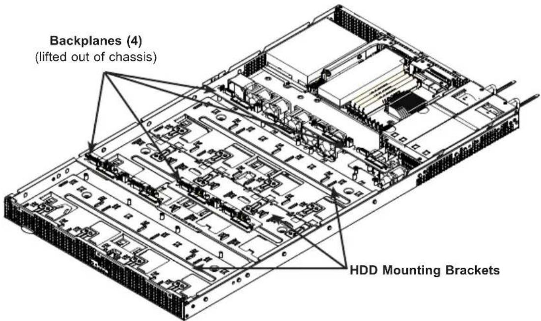
text_image
Backplanes (4) (lifted out of chassis) HDD Mounting BracketsFigure 6-3. HDD Brackets and Backplanes
Replacing a Hard Drive
This procedure is also described on the instruction sticker on the chassis cover.
-
With the optional cable arm, the system can remain powered on when replacing drives. (without the cable arm, first power down as described in Section 6-3). With the system extended from the rack, remove the top front cover.
-
Locate and press the latch on the HDD you wish to remove from the chassis (see instruction sticker).
-
Slide the HDD away from its backplane socket and lift it out. Note the number on the floor of the chassis.
-
Slide the replacement drive into the backplane socket and push it down onto the mounting bracket until it clicks into position.
Figure 6-4. Replacing HDDs

text_image
3.5" HDD Latch 1 2 3 4 5 6 7 8 9 10 11 12 BackplanesNote: numbers above indicate the logical drive locations (drive map).
6-6 System Fans
Six fans provide cooling for the chassis.
Figure 6-5. System Fans

natural_image
Technical line drawing of a server rack with internal components and mounting hardware (no text or symbols)Replacing a System Fan
- If necessary, open the top rear cover of the chassis while the system is running to locate the position of the failed fan. Do not run the server for an extended time with the cover off.
- Power down as described in Section 6-3.
- Remove the failed fan's power cable from the motherboard.
- Remove the four pins securing the fan to the fan housing.
- Lift the failed fan from the fan housing and out of the chassis.
- Place the new fan into the vacant space in the fan housing, while making sure the arrows on the top of the fan (indicating air direction) point in the same direction as the arrows on the other fans in the same fan housing.
- Reconnect the fan wires to the same chassis fan header as the previous fan.
- Power up the system and check that the fan is working properly before replacing the chassis cover.
6-6 Installing an Expansion Card
The chassis supports one low profile PCIe expansion card.
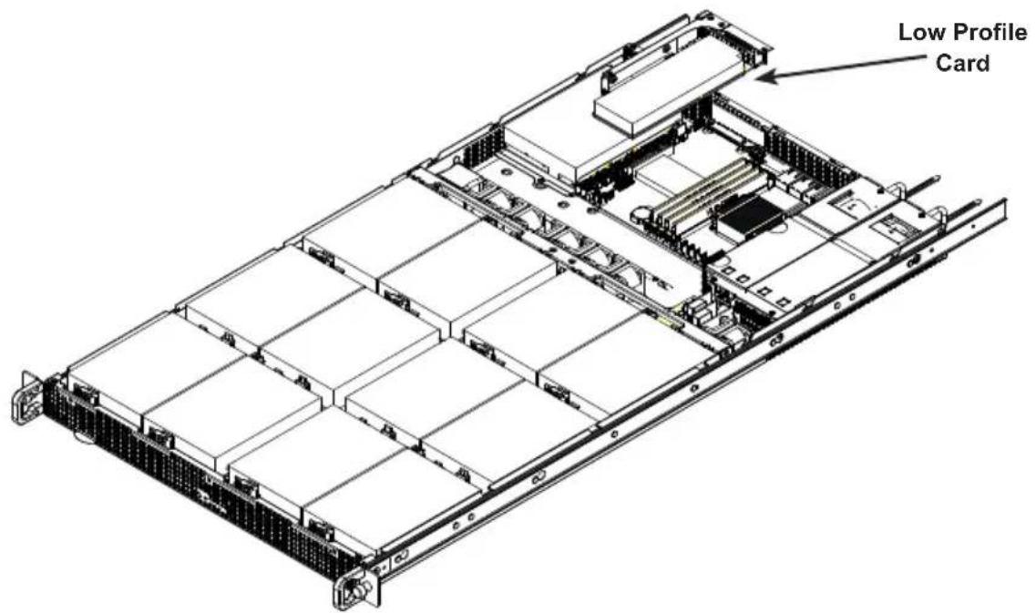
text_image
Low Profile CardFigure 6-6. Expansion Card
Installing an Expansion Card
- Locate the riser card bracket in your chassis accessory bag, and the riser card, which is purchased separately.
- Power down the system as described in Section 5-2 and remove the rear cover.
- Attach the riser card to the riser card bracket using screws.
- Insert the riser card into the motherboard expansion slot while aligning the riser card bracket with the rear of the chassis. Secure the bracket with screws.

text_image
Riser Card BracketFigure 6-7. Riser Card Bracket
- Remove the PCI shield on the rear of the chassis to expose the opening through which the PCI I/O ports will extend.
- Insert the expansion card into the slot on the riser card while aligning the expansion card backplate with the open slot in the rear of the chassis.
- Secure the card backplate to the chassis with the locking screw.
- Replace the chassis cover and power up.
6-7 Power Supply
The system has a 400 watt redundant power supply consisting of two power modules. In the event that one power module fails, the redundant module will keep the system powered on. The failed power module should be replaced as soon as possible.
This power supply is auto-switching capable, enabling it to automatically sense and operate at a 100v to 240v input voltage. New units can be ordered directly from Supermicro (see contact information in the Preface).
Replacing the Power Supply
Replacing the Power Supply
With redundant power, the system should keep running if a single power module fails.
- Remove the AC power cord from the back of the failed power supply module.
- Push the release tab on the rear of the power supply.
- Pull the power supply out of the power supply bay using the handle.
- Push the new power supply module into the power bay until it clicks.
- Plug the AC power cord back into the module.

natural_image
Top-down schematic of an electronic device chassis showing internal components and connectors (no text or labels)Figure 6-8. Power Supply Modules
Chapter 7
BIOS
7-1 Introduction
This chapter describes the AMI BIOS setup utility for the X10SDV-7TP8F motherboard. The ROM BIOS is stored in a Flash EEPROM and can be easily updated. This chapter describes the basic navigation of the AMI BIOS setup utility setup screens.
Note: For AMI BIOS Recovery, please refer to the UEFI BIOS Recovery Instructions in Appendix C.
Starting BIOS Setup Utility
To enter the AMI BIOS setup utility screens, press the
Note: In most cases, the
Each main BIOS menu option is described in this manual. The Main BIOS setup menu screen has two main frames. The left frame displays all the options that can be configured. Grayed-out options cannot be configured. Options in blue can be configured by the user. The right frame displays the key legend. Above the key legend is an area reserved for a text message. When an option is selected in the left frame, it is highlighted in white. Often a text message will accompany it. (Note: the AMI BIOS has default text messages built in. Supermicro retains the option to include, omit, or change any of these text messages.)
The AMI BIOS setup utility uses a key-based navigation system called "hot keys". Most of the AMI BIOS setup utility "hot keys" can be used at any time during the setup navigation process. These keys include
Note: Options printed in Bold are default settings.
How To Change the Configuration Data
The configuration data that determines the system parameters may be changed by entering the AMI BIOS setup utility. This setup utility can be accessed by pressing at the appropriate time during system boot.
How to Start the Setup Utility
Normally, the only visible Power-On Self-Test (POST) routine is the memory test. As the memory is being tested, press the
Warning: Do not update the BIOS unless your system has a BIOS-related issue. Flashing the wrong BIOS can cause irreparable damage to the system. In no event shall Supermicro be liable for direct, indirect, special, incidental, or consequential damages arising from a BIOS update. If you have to update the BIOS, do not shut down or reset the system while the BIOS is updating. This is to avoid possible boot failure.
7-2 Main Setup
When you first enter the AMI BIOS setup utility, you will enter the Main setup screen. You can always return to the Main setup screen by selecting the Main tab on the top of the screen. The Main BIOS Setup screen is shown below.
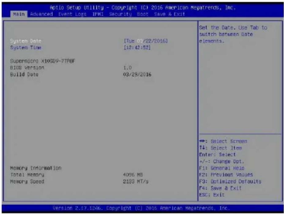
text_image
Aptio Setup Utility - Copyright (C) 2016 American Megatrends, Inc. Main Advanced Event Logs IFMI Security Boot Save & Exit System Date [Tue 03/22/2016] System Time [12:42:52] Supermicro X10SDV-7TP8F BIOS Version 1.0 Build Date 03/29/2016 Memory Information Total Memory 4096 MB Memory Speed 2193 HT/s Set the Date. Use Tab to switch between Date elements. +: Select Screen +/-: Select Item Enter: Select +/-: Change Opt. F1: General Held F2: Previous Values F3: Optimized Defaults F4: Save & Exit ESC: Exit Version 2.17.1246. Copyright (C) 2016 American Megatrends, Inc.The following Main menu items will display:
System Date/System Time
Use this feature to change the system date and time. Highlight System Date or System Time using the arrow keys. Enter new values using the keyboard. Press the
Note: The time is in the 24-hour format. For example, 5:30 P.M. appears as 17:30:00.
The following BIOS items will also be displayed:
Supermicro X10SDV-7TP8F
Version
Build Date
Memory Information
Total Memory
This displays the total size of memory available in the system.
7-3 Advanced Setup Configurations
Use the arrow keys to select Boot Setup and press
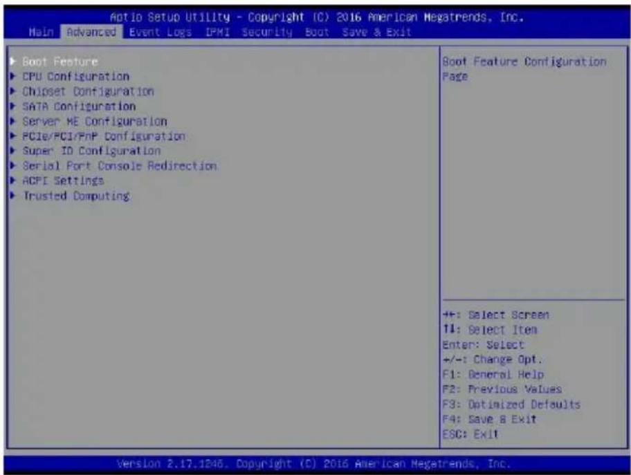
text_image
Aotio Setup Utility - Copyright (C) 2016 American Megatrends, Inc. Main Advanced Event Logs IPMI Security Boot Save & Exit Boot Feature CPU Configuration Chipset Configuration SATA Configuration Server ME Configuration PCIe/PCI/PnP Configuration Super ID Configuration Serial Port Console Redirection ACPI Settings Trusted Computing Boot Feature Configuration Page +/-: Select Screen 11: Select Item Enter: Select +/-: Change Opt. F1: General Help F2: Previous Values F3: Optimized Defaults F4: Save & Exit ESC: Exit Version 2.17.1246. Copyright (C) 2016 American Megatrends, Inc.Warning: Take caution when changing the Advanced settings. An incorrect value, a very high DRAM frequency, or an incorrect DRAM timing setting may make the system unstable. When this occurs, revert to the default to the manufacture default settings.
▶Boot Feature
Quiet Boot
Use this feature to select the screen display between the POST messages and the OEM logo upon bootup. Select Disabled to display the POST messages. Select Enabled to display the OEM logo instead of the normal POST messages. The options are Enabled and Disabled.
AddOn ROM Display Mode
Use this feature to set the display mode for the Option ROM. Select Keep Current to display the current AddOn ROM setting. Select Force BIOS to use the Option ROM display set by the system BIOS. The options are Force BIOS and Keep Current.
Bootup NumLock State
Use this feature to set the Power-on state for the
Wait For 'F1' If Error
Use this feature to force the system to wait until the 'F1' key is pressed if an error occurs. The options are Disabled and Enabled.
INT19 (Interrupt 19) Trap Response
Interrupt 19 is the software interrupt that handles the boot disk function. When this item is set to Immediate, the ROM BIOS of the host adaptors will "capture" Interrupt 19 at bootup immediately and allow the drives that are attached to these host adaptors to function as bootable disks. If this item is set to Postponed, the ROM BIOS of the host adaptors will not capture Interrupt 19 immediately and allow the drives attached to these adaptors to function as bootable devices at bootup. The options are Immediate and Postponed.
Re-try Boot
If this item is enabled, the BIOS will automatically reboot the system from a specified boot device after its initial boot failure. The options are Disabled, Legacy Boot, and EFI Boot.
▶Power Configuration
Watch Dog Function
If enabled, the Watch Dog Timer will allow the system to reset or generate NMI based on jumper settings when it is expired for more than 5 minutes. The options are Enabled and Disabled.
Power Button Function
This feature controls how the system shuts down when the power button is pressed. Select 4 Seconds Override for the user to power off the system after pressing and holding the power button for 4 seconds or longer. Select Instant Off to instantly power off the system as soon as the user presses the power button. The options are 4 Seconds Override and Instant Off.
Restore on AC Power Loss
Use this feature to set the power state after a power outage. Select Stay-Off for the system power to remain off after a power loss. Select Power-On for the system power to be turned on after a power loss. Select Last State to allow the system to resume its last power state before a power loss. The options are Power On, Stay Off, and Last State.
▶CPU Configuration
The following CPU information will be displayed:
- Processor ID
- Processor Frequency
- Processor Max Ratio
- Processor Min Ratio
- Microcode Revision
- L1 Cache RAM
• L2 Cache RAM
• L3 Cache Ram - CPU Version
Clock Spread Spectrum
If this feature is set to Enabled, the BIOS utility will monitor the level of Electromagnetic Interference caused by the components and will attempt to reduce the interference whenever needed. The options are Disable and Enable.
Hyper-Threading (ALL)
Select Enable to use Intel Hyper-Threading Technology to enhance CPU performance. The options are Disable and Enable.
Cores Enabled
Set a numeric value to enable the number of cores. (Please refer to Intel's website for more information.) Enter 0 to enable all cores.
Monitor/Mwait
Select Enabled to enable the Monitor/MWait instructions. The Monitor instruction monitors a region of memory for writes, and MWait instructions instruct the CPU to stop until the monitored region begins to write. The options are Disable and Enable.
Execute Disable Bit (Available if supported by the OS & the CPU)
Select Enabled to enable the Execute-Disable Bit which will allow the processor to designate areas in the system memory where an application code can execute and where it cannot, thus preventing a worm or a virus from flooding illegal codes to overwhelm the processor or damage the system during an attack. The default is Enable. (Refer to the Intel® and Microsoft® websites for more information.)
PPIN Control
Select Unlock/Enable to use the Protected-Processor Inventory Number (PPIN) in the system. The options are Unlock/Enable and Unlock/Disable.
Hardware Prefetcher (Available when supported by the CPU)
If set to Enabled, the hardware prefetcher will prefetch streams of data and instructions from the main memory to the L2 cache to improve CPU performance. The options are Disable and Enable.
Adjacent Cache Prefetch (Available when supported by the CPU)
The CPU prefetches the cache line for 64 bytes if this feature is set to Disabled. The CPU prefetches both cache lines for 128 bytes as comprised if this feature is set to Enable.
DCU Streamer Prefetcher (Available when supported by the CPU)
Select Enabled to enable the DCU (Data Cache Unit) Streamer Prefetcher which will stream and prefetch data and send it to the Level 1 data cache to improve data processing and system performance. The options are Disable and Enable.
DCU IP Prefetcher (Available when supported by the CPU)
Select Enabled for DCU (Data Cache Unit) IP Prefetcher support, which will prefetch IP addresses to improve network connectivity and system performance. The options are Disable and Enable.
Direct Cache Access (DCA)
Select Enabled to use Intel's DCA (Direct Cache Access) Technology to improve data transfer efficiency. The options are Disable, Enable, and Auto.
Intel® Virtualization Technology (Available when supported by the CPU)
Select Enabled to support Intel Virtualization Technology, which will allow one platform to run multiple operating systems and applications in independent partitions, creating multiple "virtual" systems in one physical computer. The options are Disable and Enable.

Note: If a change is made to this setting, you will need to reboot the system for the change to take effect. Refer to Intel's website for detailed information.
▶Advanced Power Management Configuration
This section is used to configure the following CPU Power Management settings.
EIST (P-States)
EIST (Enhanced Intel SpeedStep Technology) allows the system to automatically adjust processor voltage and core frequency to reduce power consumption and heat dissipation. The options are Disable and Enable.
If the above is set to Enable, CPU P State will display:
▶CPU P State Control
P State Domain
This feature allows the user to indicate the P-State domain for each logical process in the system. All processes indicate the same domain in the same package. The options are ALL and ONE.
P-State Coordination
This feature allows the user to change the P-State (Power-Performance State) coordination type. P-State is also known as "SpeedStep" for Intel processors. Select HW_ALL to change the P-State coordination type for hardware components only. Select SW_ALL to change the P-State coordination type for all software installed in the system. Select SW_ANY to change the P-State coordination type for a software program in the system. The options are HW_All, SW_ALL, and SW_ANY.
Energy Efficient P-State
Select Enable to support power-saving mode for P-State. The options are Disable and Enable.
Boot Performance Mode
This feature allows the user to select the performance state that the BIOS will set before the operating system handoff. The options are Max Performance and Max Efficient.
Turbo Mode
Select Enable for processor cores to run faster than the frequency specified by the manufacturer. The options are Disable and Enable.
▶CPU HWPM State Control
Enable CPU HWPM
Select Enable for better CPU energy performance. The options are Disable, HWPM NATIVE MODE, and HWPM OOB MODE.
Enable CPU Autonomous Cstate
Use this feature to enable CPU Autonomous C State, which converts HALT instructions to Mwait. The options are Disable and Enable.
▶CPU C State Control
CPU C State
Use this feature to enable the enahnced C State of the CPU. The options are Disable and Enable.
Package C State Limit
This feature allows the user to set the limit on the C State package register. The options are C0/C1 State, C2 State, C6 (Non Retention) State, and C6 (Rentention) state.
CPU C3 Report
Select Enabled to allow the BIOS to report the CPU C3 State (ACPI C2) to the operating system. During the CPU C3 State, the CPU clock generator is turned off. The options are Enable and Disable.
CPU C6 Report
Select Enabled to allow the BIOS to report the CPU C6 State (ACPI C3) to the operating system. During the CPU C6 State, the power to all cache is turned off. The options are Disable and Enable.
Enhanced Halt State (C1E)
Select Enabled to use Enhanced Halt-State technology, which will significantly reduce the CPU's power consumption by reducing the CPU's clock cycle and voltage during a Halt-state. The options are Disable and Enable.
▶CPU T State Control
ACPI (Advanced Configuration Power Interface) T-States
Select Enable to support CPU throttling by the operating system to reduce power consumption. The options are Disable and Enable.
▶CPU Advanced PM Turning
▶Energy Perf BIAS
Energy Performance Tuning
When enabled, this item selects whether the BIOS or Operating System can turn on the energy performance bias tuning. The options are Disable and Enable.
If the above is set to Disable, Energy Performance BIAS Setting will display:
Energy Performance BIAS Setting
This feature allows balancing Power Efficiency vs Performance. This will override whatever setting is in the Operating System. The options are Performance, Balanced Performance, Balanced Power, and Power.
Power/Performance Switch
This feature allows dynamic switching between Power and Performance power efficiency. The options are Disable and Enable.
Workload Configuration
This feature allows for optimization of workload. Balanced is recommended. The options are Balanced and I/O Sensitive.
▶Program PowerCTL\_MSR
PKG C-state Lat. Neg.
Use this feature to indicate whether latency should be negotiated with PCH for packaging C-States. The options are Enable and Disable.
SAPM Control
This feature indicates whether the PCU should control the System Agent PM using its power-performance tuning algorithm. The options are Enable and Disable.
Energy Efficient Turbo
Use this feature to enable energy efficient turbo mode. The options are Enable and Disable.
▶DRAM RAPL Configuration
Override BW\_LIMIT\_TF
This feature allows the user to turn off the "Override BW_LIMIT_TF (Time Frame)" setting when the item "Running Average Limit for DRAM modules" (DRAM RAPL) is set to Enabled so that the DRAM RAPL setting can work properly. The default setting is 1.
DRAM RAPL Extended Range
Use this feature to set the DRAM Running Average Power Limit (RAPL) Extended Range. The options are Disable and Enable.
▶Chipset Configuration
Warning: Setting the wrong values in the following features may cause the system to malfunction.
▶North Bridge
This feature allows the user to configure the following North Bridge settings.
▶IIO Configuration
EV DFX (Device Function On-Hide) Features
When this feature is set to Enable, the EV_DFX Lock Bits that are located on a processor will always remain clear during electric tuning. The options are Disable and Enable.
▶IIO1 Configuration
M.2 PCI-E 3.0 X4
This item configures the link speed of the PCI-E port specified by the user. The options are Gen 1 (Generation 1) (2.5 GT/s), Gen 2 (Generation 2) (5 GT/s), and Gen 3 (Generation 3) (8 GT/s).
CPU SLOT 6 PCI-E 3.0 X8
This item configures the link speed of the PCI-E port specified by the user. The options are Gen 1 (Generation 1) (2.5 GT/s), Gen 2 (Generation 2) (5 GT/s), and Gen 3 (Generation 3) (8 GT/s).
CPU SLOT 7 PCI-E 3.0 X8
This item configures the link speed of the PCI-E port specified by the user. The options are Gen 1 (Generation 1) (2.5 GT/s), Gen 2 (Generation 2) (5 GT/s), and Gen 3 (Generation 3) (8 GT/s).
▶IOAT (Intel® IO Acceleration) Configuration
Enable IOAT
Select Enable to enable Intel I/OAT (I/O Acceleration Technology) support, which significantly reduces CPU overhead by leveraging CPU architectural improvements and freeing the system resource for other tasks. The options are Disable and Enable.
No Snoop
Select Enable to support no-snoop mode for each CB device. The options are Disable and Enable.
▶Intel® VT for Directed I/O (VT-d)
Intel VT for Directed I/O (VT-d)
Select Enable to use Intel Virtualization Technology support for Direct I/O VT-d support by reporting the I/O device assignments to the VMM (Virtual Machine Monitor) through the DMAR ACPI Tables. This feature offers fully-protected I/O resource sharing across Intel platforms, providing greater reliability, security and availability in networking and data-sharing. The options are Enable and Disable.
ACS Control
Use this feature to program Access Control Services (ACS) to the PCI-E Root Port Bridges. The options are Enable and Disable.
Interrupt Remapping
Select Enable for Interrupt Remapping support to enhance system performance. The options are Enable and Disable.
▶ Memory Configuration
Enforce POR
Select Enable to enforce POR restrictions on DDR4 frequency and voltage programming. The options are Enabled and Disabled.
Memory Frequency
Use this feature to set the maximum memory frequency for onboard memory modules. The options are Auto, 1333, 1400, 1600, 1800, 1867, 2000, 2133, 2200, 2400, 2600, 2667, 2800, 2993, 3000, 3200, and Reserved (Do not select Reserved).
Data Scrambling
Select Enabled to enable data scrambling to enhance system performance and data integrity. The options are Auto, Disabled, and Enabled.
DRAM RAPL Baseline
Use this feature to set the run-time power-limit baseline for DRAM modules. The options are Disable, DRAM RAPL Mode 0, and DRAM RAPL Mode 1.
Set Throttling Mode
Throttling improves reliability and reduces power consumption in the processor via automatic voltage control during processor idle states. The options are Disabled and CLTT (Closed Loop Thermal Throttling).
A7 Mode
Select Enabled to support the A7 (Addressing) mode to improve memory performance. The options are Enable and Disable.
▶DIMM Information
This item displays the status of a DIMM module specified by the user.
• DIMMA1
• DIMMB1
• DIMMA2
DIMMB2
▶Memory RAS (Reliability\_Availability\_Serviceability) Configuration
Use this submenu to configure the following Memory RAS settings.
Patrol Scrub
Patrol Scrubbing is a process that allows the CPU to correct correctable memory errors detected on a memory module and send the correction to the requestor (the original source). When this item is set to Enabled, the IO hub will read and write back one cache line every 16K cycles, if there is no delay caused by internal processing. By using this method, roughly 64 GB of memory behind the IO hub will be scrubbed every day. The options are Enable and Disable.
Patrol Scrub Interval
This feature allows you to decide how many hours the system should wait before the next complete patrol scrub is performed. Use the keyboard to enter a value from 0-24. The default setting is 24.
Demand Scrub
Demand Scrubbing is a process that allows the CPU to correct correctable memory errors found on a memory module. When the CPU or I/O issues a demand-read command, and the read data from memory turns out to be a correctable error, the error is corrected and sent to the requestor (the original source). Memory is updated as well. Select Enable to use Demand Scrubbing for ECC memory correction. The options are Disable and Enable.
Device Tagging
Select Enable to support device tagging. The options are Disable and Enable.
▶ South Bridge
The following South Bridge information will display:
- USB Configuration
- USB Module Version
- USB Devices
Legacy USB Support
This feature enables support for legacy USB devices. Select Auto to disable legacy support if USB devices are not present. Select Disable to have USB devices available only for EFI applications. The options are Enabled, Disabled, and Auto.
XHCI Hand-Off
This is a work-around solution for operating systems that do not support XHCI (Extensible Host Controller Interface) hand-off. The XHCI ownership change should be claimed by the XHCI driver. The settings are Enabled and Disabled.
EHCI Hand-Off
This item is for the Operating Systems that do not support Enhanced Host Controller Interface (EHCI) hand-off. When this item is enabled, EHCI ownership change will be claimed by the EHCI driver. The settings are Enabled and Disabled.
USB 3.0 Support
Select Enabled for USB 3.0 support. The options are Smart Auto, Auto, Enabled, Disabled.
EHCI1
Select Enabled to enable EHCI (Enhanced Host Controller Interface) support on USB 2.0 connector #1 (at least one USB 2.0 connector should be enabled for EHCI support). The options are Disabled and Enabled.
EHCI2
Select Enabled to enable EHCI (Enhanced Host Controller Interface) support on USB 2.0 connector #2 (at least one USB 2.0 connector should be enabled for EHCI support). The options are Disabled and Enabled.
XHCI Pre-Boot Driver
Select Enabled to enable XHCI (Extensible Host Controller Interface) support on a pre-boot drive specified by the user. The options are Enabled and Disabled.
▶SATA Configuration
When this submenu is selected, the AMI BIOS automatically detects the presence of the SATA devices that are supported by the Intel PCH chip and displays the following items:
SATA Controller
This item enables or disables the onboard SATA controller supported by the Intel PCH chip. The options are Enabled and Disabled.
Configure SATA as
Select IDE to configure a SATA drive specified by the user as an IDE drive. Select AHCI to configure a SATA drive specified by the user as an AHCI drive. Select RAID to configure a SATA drive specified by the user as a RAID drive. The options are IDE, AHCI, and RAID.
*If the item "Configure SATA as" is set to AHCI, the following items will display:
SATA Frozen
Use this item to enable the HDD Security Frozen Mode. The options are Disabled and Enabled.
SATA AHCI LPM
Use this feature to enable the Link Power Management for SATA AHCI. The options are Disabled and Enabled.
Support Aggressive Link Power Mgmt
When this item is set to Enabled, the SATA AHCI controller manages the power usage of the SATA link. The controller will put the link in a low power mode during extended periods of I/O inactivity, and will return the link to an active state when I/O activity resumes. The options are Disabled and Enabled.
SATA RAID Option ROM/UEFI Driver (Available if "Configure SATA As" is set to RAID)
Select Enabled to use the SATA RAID Option ROM/UEFI driver for system boot. The options are Enabled and Disabled.
SATA Port 0\~ Port 5
This item displays the information detected on the installed SATA drive on the particular SATA port.
• Model number of drive and capacity
• Software Preserve Support
Port 0 \~ Port 5 Hot Plug
This feature designates this port for hot plugging. Set this item to Enabled for hot-plugging support, which will allow the user to replace a SATA drive without shutting down the system. The options are Enabled and Disabled.
Port 0 \~ Port 5 Spin Up Device
On an edge detect from 0 to 1, set this item to allow the PCH to initialize the device. The options are Enabled and Disabled.
Port 0 \~ Port 5 SATA Device Type
Use this item to specify if the SATA port specified by the user should be connected to a Solid State drive or a Hard Disk Drive. The options are Hard Disk Drive and Solid State Drive.
*If the item "Configure SATA as" is set to IDE, the following items will display:
SATA Frozen
Use this item to enable the HDD Security Frozen Mode. The options are Disabled and Enabled.
Port 0 \~ Port 4 SATA Device Type (Available when a SATA port is detected)
Use this item to specify if the SATA port specified by the user should be connected to a Solid State drive or a Hard Disk Drive. The options are Hard Disk Drive and Solid State Drive.
▶Server ME (Management Engine) Configuration
This feature displays the following system ME configuration settings.
- General ME Configuration
• Operational Firmware Version
• ME Firmware Type
• Recovery Firmware Version
• ME Firmware Features
• ME Firmware Status #1
• ME Firmware Status #2 - Current State
- Error Code
▶PCIe/PCI/PnP Configuration
The following information will display:
• PCI Bus Driver Version
• PCI Devices Common Settings:
PCI PERR/SERR Support
Select Enabled to allow a PCI device to generate a PERR/SERR number for a PCI Bus Signal Error Event. The options are Enabled and Disabled.
Above 4G Decoding (Available if the system supports 64-bit PCI decoding)
Select Enabled to decode a PCI device that supports 64-bit in the space above 4G Address. The options are Disabled and Enabled.
SR-IOV (Available if the system supports Single-Root Virtualization)
Select Enabled for Single-Root IO Virtualization support. The options are Disabled and Enabled.
Maximum Payload
Use this feature to select the setting for the PCI Express maximum payload size. The options are Auto, 128 Bytes, 256 Bytes, 512 Bytes, 1024 Bytes, 2048 Bytes, and 4096 Bytes.
Relaxed Ordering
Select Enable to enable Relaxed Ordering support which will allow certain transactions to violate the strict-ordering rules of PCI bus for a transaction to be completed prior to other transactions that have already been enqueued. The options are Disabled and Enabled.
Extended Tag
Use this item to allow a device to use the 8-bit tag field as a requester. The options are Disabled and Enabled.
ARI Forwarding
When this feature is enabled, the Downstream Port disables its traditional device number to 0 when turning Type1 Configuration Request into a Type0 Configuration Request. The default value is Disabled.
M.2 PCI-E 3.0 X4
Use this feature to select which firmware type to be loaded for the add-on card in this slot. The options are Disabled, Legacy, and EFI.
CPU SLOT 6 PCI-E 3.0 X8 OPROM
Use this feature to select which firmware type to be loaded for the add-on card in this slot. The options are Disabled, Legacy, and EFI.
CPU SLOT 7 PCI-E 3.0 X8 OPROM
Use this feature to select which firmware type to be loaded for the add-on card in this slot. The options are Disabled, Legacy, and EFI.
PCI-E 2.0 X1 OPROM
Use this feature to select which firmware type to be loaded for the add-on card in this slot. The options are Disabled, Legacy, and EFI.
Onboard SAS Option ROM
Use this feature to select which firmware to be loaded for the onboard SAS Option ROM. The options are Disabled, Legacy, and EFI.
Onboard LAN Option ROM Type
Use this feature to select which firmware to be loaded for the onboard LAN. The options are Legacy and EFI.
Onboard LAN1 Option ROM
Use this option to select the type of device installed in LAN Port1 used for system boot. The default setting for LAN1 Option ROM is PXE.
Onboard LAN2 \~ LAN8 Option ROM
Use this option to select the type of device installed in the specified LAN Ports used for system boot. The options are Disabled and PXE.
Onboard Video Option ROM
Use this item to select the Onboard Video Option ROM type. The options are Disabled, Legacy, and EFI.
VGA Priority
This feature allows the user to select the graphics adapter to be used as the primary boot device. The options are Onboard and Offboard.
Network Stack
Select Enabled enable PXE (Preboot Execution Environment) or UEFI (Unified Extensible Firmware Interface) for network stack support. The options are Enabled and Disabled.
*If "Network Stack" is set to Enabled, the four items below will become available for configuration:
IPv4 PXE Support
Select Enabled to enable IPv4 PXE boot support. The options are Disabled and Enabled.
IPv6 PXE Support
Select Enabled to enable IPv6 PXE boot support. The options are Disabled and Enabled.
PXE boot wait time
Use this option to specify the wait time to press the ESC key to abort the PXE boot. Press "+" or "-" on your keyboard to change the value. The default setting is 0.
Media detect count
Use this option to specify the number of times media will be checked. Press "+" or "-" on your keyboard to change the value. The default setting is 1.
▶Super IO Configuration
Super IO Chip AST2400
▶ Serial Port 1 Configuration
This submenu allows the user the configure settings of Serial Port 1 or Serial Port 2.
Serial Port
Select Enabled to enable the selected onboard serial port. The options are Disabled and Enabled.
Device Settings
This item displays the status of a serial part specified by the user.
Change Port 1 Settings
This feature specifies the base I/O port address and the Interrupt Request address of a serial port specified by the user. Select Auto to allow the BIOS to automatically assign the base I/O and IRQ address.
The options for Serial Port 1 are Auto, (IO=3F8h; IRQ=4), (IO=3F8h; IRQ=3, 4, 5, 6, 7, 9, 10, 11, 12), (IO=2F8h; IRQ=3, 4, 5, 6, 7, 9, 10, 11, 12), (IO=3E8h; IRQ=3, 4, 5, 6, 7, 9, 10, 11, 12) and (IO=2E8h; IRQ=3, 4, 5, 6, 7, 9, 10, 11, 12).
▶Serial Port Console Redirection
COM1 Console Redirection
Console Redirection
Select Enabled to enable console redirection support for a serial port specified by the user. The options are Disabled and Enabled.
▶COM1 Console Redirection Settings
This feature allows the user to specify how the host computer will exchange data with the client computer, which is the remote computer used by the user.
Terminal Type
This feature allows the user to select the target terminal emulation type for Console Redirection. Select VT100 to use the ASCII Character set. Select VT100+ to add color and function key support. Select ANSI to use the Extended ASCII Character Set. Select VT-UTF8 to use UTF8 encoding to map Unicode characters into one or more bytes. The options are ANSI, VT100, VT100+, and VT-UTF8.
Bits Per second
Use this feature to set the transmission speed for a serial port used in Console Redirection. Make sure that the same speed is used in the host computer and the client computer. A lower transmission speed may be required for long and busy lines. The options are 9600, 19200, 38400, 57600, and 115200 (bits per second).
Data Bits
Use this feature to set the data transmission size for Console Redirection. The options are 7 Bits and 8 Bits.
Parity
A parity bit can be sent along with regular data bits to detect data transmission errors. Select Even if the parity bit is set to 0, and the number of 1's in data bits is even. Select Odd if the parity bit is set to 0, and the number of 1's in data bits is odd. Select None if you do not want to send a parity bit with your data bits in transmission. Select Mark to add a mark as a parity bit to be sent along with the data bits. Select Space to add a Space as a parity bit to be sent with your data bits. The options are None, Even, Odd, Mark and Space.
Stop Bits
A stop bit indicates the end of a serial data packet. Select 1 Stop Bit for standard serial data communication. Select 2 Stop Bits if slower devices are used. The options are 1 and 2.
Flow Control
Use this feature to set the flow control for Console Redirection to prevent data loss caused by buffer overflow. Send a "Stop" signal to stop sending data when the receiving buffer is full. Send a "Start" signal to start sending data when the receiving buffer is empty. The options are None and Hardware RTS/CTS.
VT-UTF8 Combo Key Support
Select Enabled to enable VT-UTF8 Combination Key support for ANSI/VT100 terminals. The options are Disabled and Enabled.
Recorder Mode
Select Enabled to capture the data displayed on a terminal and send it as text messages to a remote server. The options are Disabled and Enabled.
Resolution 100x31
Select Enabled for extended-terminal resolution support. The options are Disabled and Enabled.
Legacy OS Redirection Resolution
Use this feature to select the number of rows and columns used in Console Redirection for legacy OS support. The options are 80x24 and 80x25.
Putty KeyPad
This feature selects the settings for Function Keys and KeyPad used for Putty, which is a terminal emulator designed for the Windows OS. The options are VT100, LINUX, XTERMR6, SC0, ESCN, and VT400.
Redirection After BIOS POST
Use this feature to enable or disable legacy console redirection after BIOS POST. When set to Bootloader, legacy console redirection is disabled before booting the OS. When set to Always Enable, legacy console redirection remains enabled when booting the OS. The options are Always Enable and Bootloader.
SOL Console Redirection
Select Enabled to use the SOL port for Console Redirection. The options are Disabled and Enabled.
*If the item above set to Enabled, the following items will become available for user's configuration:
▶SOL Console Redirection Settings
Use this feature to specify how the host computer will exchange data with the client computer, which is the remote computer used by the user.
Terminal Type
Use this feature to select the target terminal emulation type for Console Redirection. Select VT100 to use the ASCII Character set. Select VT100+ to add color and
function key support. Select ANSI to use the Extended ASCII Character Set. Select VT-UTF8 to use UTF8 encoding to map Unicode characters into one or more bytes. The options are ANSI, VT100, VT100+, and VT-UTF8.
Bits Per second
Use this feature to set the transmission speed for a serial port used in Console Redirection. Make sure that the same speed is used in the host computer and the client computer. A lower transmission speed may be required for long and busy lines. The options are 9600, 19200, 38400, 57600 and 115200 (bits per second).
Data Bits
Use this feature to set the data transmission size for Console Redirection. The options are 7 (Bits) and 8 (Bits).
Parity
A parity bit can be sent along with regular data bits to detect data transmission errors. Select Even if the parity bit is set to 0, and the number of 1's in data bits is even. Select Odd if the parity bit is set to 0, and the number of 1's in data bits is odd. Select None if you do not want to send a parity bit with your data bits in transmission. Select Mark to add a mark as a parity bit to be sent along with the data bits. Select Space to add a Space as a parity bit to be sent with your data bits. The options are None, Even, Odd, Mark and Space.
Stop Bits
A stop bit indicates the end of a serial data packet. Select 1 Stop Bit for standard serial data communication. Select 2 Stop Bits if slower devices are used. The options are 1 and 2.
Flow Control
Use this feature to set the flow control for Console Redirection to prevent data loss caused by buffer overflow. Send a "Stop" signal to stop sending data when the receiving buffer is full. Send a "Start" signal to start sending data when the receiving buffer is empty. The options are None and Hardware RTS/CTS.
VT-UTF8 Combo Key Support
Select Enabled to enable VT-UTF8 Combination Key support for ANSI/VT100 terminals. The options are Disabled and Enabled.
Recorder Mode
Select Enabled to capture the data displayed on a terminal and send it as text messages to a remote server. The options are Disabled and Enabled.
Resolution 100x31
Select Enabled for extended-terminal resolution support. The options are Disabled and Enabled.
Legacy OS Redirection Resolution
Use this feature to select the number of rows and columns used in Console Redirection for legacy OS support. The options are 80x24 and 80x25.
Putty KeyPad
This feature selects Function Keys and KeyPad settings for Putty, which is a terminal emulator designed for the Windows OS. The options are VT100, LINUX, XTERMR6, SCO, ESCN, and VT400.
Redirection After BIOS POST
Use this feature to enable or disable legacy Console Redirection after BIOS POST. When set to Bootloader, legacy Console Redirection is disabled before booting the OS. When set to Always Enable, legacy Console Redirection remains enabled when booting the OS. The options are Always Enable and Bootloader.
Serial Port for Out-of-Band Management/Windows Emergency Management Services (EMS)
The submenu allows the user to configure Console Redirection settings to support Out-of-Band Serial Port management.
EMS (Emergency Management Services) Console Redirection
Select Enabled to use a COM port selected by the user for EMS Console Redirection. The options are Enabled and Disabled.
*If the item above set to Enabled, the following items will become available for user's configuration:
▶EMS Console Redirection Settings
This feature allows the user to specify how the host computer will exchange data with the client computer, which is the remote computer used by the user.
Out-of-Band Mgmt Port
The feature selects a serial port in a client server to be used by the Microsoft Windows Emergency Management Services (EMS) to communicate with a remote host server. The options are COM1 and COM2/SOL.
Terminal Type
Use this feature to select the target terminal emulation type for Console Redirection. Select VT100 to use the ASCII character set. Select VT100+ to add color and
function key support. Select ANSI to use the extended ASCII character set. Select VT-UTF8 to use UTF8 encoding to map Unicode characters into one or more bytes. The options are ANSI, VT100, VT100+, and VT-UTF8.
Bits Per Second
This item sets the transmission speed for a serial port used in Console Redirection. Make sure that the same speed is used in the host computer and the client computer. A lower transmission speed may be required for long and busy lines. The options are 9600, 19200, 57600, and 115200 (bits per second).
Flow Control
Use this item to set the flow control for Console Redirection to prevent data loss caused by buffer overflow. Send a "Stop" signal to stop sending data when the receiving buffer is full. Send a "Start" signal to start sending data when the receiving buffer is empty. The options are None, Hardware RTS/CTS, and Software Xon/Xoff.
Data Bits
Use this feature to set the data transmission size for Console Redirection. The options are 7 (Bits) and 8 (Bits).
Parity
A parity bit can be sent along with regular data bits to detect data transmission errors. Select Even if the parity bit is set to 0, and the number of 1's in data bits is even. Select Odd if the parity bit is set to 0, and the number of 1's in data bits is odd. Select None if you do not want to send a parity bit with your data bits in transmission. Select Mark to add a mark as a parity bit to be sent along with the data bits. Select Space to add a Space as a parity bit to be sent with your data bits. The options are None, Even, Odd, Mark and Space.
Stop Bits
A stop bit indicates the end of a serial data packet. Select 1 Stop Bit for standard serial data communication. Select 2 Stop Bits if slower devices are used. The options are 1 and 2.
▶ACPI Settings
WHEA Support
This feature Enables the Windows Hardware Error Architecture (WHEA) support for the Windows 2008 (or a later version) operating system. The options are Disabled and Enabled.
High Precision Event Timer
Select Enabled to activate the High Performance Event Timer (HPET) that produces periodic interrupts at a much higher frequency than a Real-time Clock (RTC) does in synchronizing multimedia streams, providing smooth playback and reducing the dependency on other timestamp calculation devices, such as an x86 RDTSC Instruction embedded in the CPU. The High Performance Event Timer is used to replace the 8254 Programmable Interval Timer. The options are Disabled and Enabled.
PCI AER Support
Select Enabled to enable the ACPI OS to manage PCI Advanced Error Reporting. The options are Disabled and Enabled.
▶Trusted Computing
Configuration
Security Device Support
If this feature and the TPM jumper on the motherboard are both set to Enabled, onboard security devices will be enabled for TPM (Trusted Platform Module) support to enhance data integrity and network security. Please reboot the system for a change on this setting to take effect. The options are Disabled and Enabled.
TPM State
This feature changes the TPM State. The options are Disabled and Enabled.
Note: The system will restart to change the TPM State.
Pending operation
Use this item to schedule a TPM-related operation to be performed by a security device for system data integrity. Your system will reboot to carry out a pending TPM operation. The options are None and TPM Clear.
Device Select
Use this feature to select the TPM version. TPM 1.2 will restrict support to TPM 1.2 devices. TPM 2.0 will restrict support for TPM 2.0 devices. Select Auto to enable support for both versions. The default setting is Auto.
The following are informational status messages that indicate the current TPM State:
TPM Enabled Status
TPM Active Status
TPM Owner Status
TXT Support
Intel TXT (Trusted Execution Technology) helps protect against software-based attacks and ensures protection, confidentiality and integrity of data stored or created

text_image
Aptio Setup Utility - Copyright (C) 2016 American Megatrends, Inc. Main Advanced Event Logs IPM1 Security Boot Save & Exit Change SMBIOS Event Log Settings View SMBIOS Event Log Presson the system. Use this feature to enable or disable TXT Support. The options are Disabled and Enabled.
7-4 Event Logs
Use this feature to configure Event Log settings.
▶Change SMBIOS Event Log Settings
Enabling/Disabling Options
SMBIOS Event Log
Change this item to enable or disable all features of the SMBIOS Event Logging during system boot. The options are Enabled and Disabled.
Runtime Error Logging Support
Select Enabled to support Runtime Error Logging. The options are Enable and Disable. If this item is set to Enable, the following item will be available for configuration:
Memory Corrected Error Enabling (Available when the item above - Runtime Error Logging Support is set to Enable)
Select Enable for the BIOS to correct a memory error if it is correctable. The options are Disable and Enable.
Memory Corr. Error Threshold
Use this item to enter the threshold value for correctable memory errors. The default setting is 10.
PCI-Ex (PCI-Express) Error Enable
Select Yes for the BIOS to correct errors occurred in the PCI-E slots. The options are Yes and No.
Erasing Settings
Erase Event Log
If No is selected, data stored in the event log will not be erased. Select Yes, Next Reset, data in the event log will be erased upon next system reboot. Select Yes, Every Reset, data in the event log will be erased upon every system reboot. The options are No, Yes, Next reset, and Yes, Every reset.
When Log is Full
Select Erase Immediately for all messages to be automatically erased from the event log when the event log memory is full. The options are Do Nothing and Erase Immediately.
SMBIOS Event Long Standard Settings
Log System Boot Event
This option toggles the System Boot Event logging to enabled or disabled. The options are Disabled and Enabled.
MECI
The Multiple Event Count Increment (MECI) counter counts the number of occurrences that a duplicate event must happen before the MECI counter is incremented. This is a numeric value. The default value is 1.
METW
The Multiple Event Time Window (METW) defines number of minutes must pass between duplicate log events before MECI is incremented. This is in minutes, from 0 to 99. The default value is 60.
Note: After making changes on a setting, be sure to reboot the system for the changes to take effect.
▶View SMBIOS Event Log
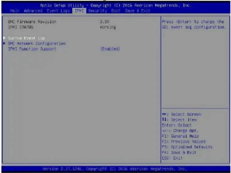
text_image
Aptio Setup Utility - Copyright (C) 2016 American Megatrends, Inc. Main Advanced Event Log IPMI Security Boot Save & Exit BMC Firmware Revision 3.90 IPMI STATUS Honking ► System Event Log ► BMC Network Configuration IPMI Function Support [Enabled] PressThis section displays the contents of the SMBIOS Event Log.
7-5 IPMI
Use this feature to configure Intelligent Platform Management Interface (IPMI) settings.
BMC Firmware Revision
This item indicates the IPMI firmware revision used in your system.
IPMI STATUS (Baseboard Management Controller)
This item indicates the status of the IPMI firmware installed in your system.
▶System Event Log
Enabling/Disabling Options
SEL Components
Select Enabled for all system event logging at bootup. The options are Enabled and Disabled.
Erasing Settings
Erase SEL
Select Yes, On next reset to erase all system event logs upon next system reboot. Select Yes, On every reset to erase all system event logs upon each system reboot. Select No to keep all system event logs after each system reboot. The options are No, Yes, On next reset, and Yes, On every reset.
When SEL is Full
This feature allows the user to decide what the BIOS should do when the system event log is full. Select Erase Immediately to erase all events in the log when the system event log is full. The options are Do Nothing and Erase Immediately.
Note: After making changes on a setting, be sure to reboot the system for the changes to take effect.
▶BMC Network Configuration
BMC Network Configuration
IPMI LAN Selection
This item displays the IPMI LAN setting. The default setting is Failover.
IPMI Network Link Status
This item displays the IPMI Network Link status. The default setting is Shared LAN.
Update IPMI LAN Configuration
Select Yes for the BIOS to implement all IP/MAC address changes at the next system boot. The options are No and Yes
Configuration Address Source (Available for configuration if "Update IPMI LAN Configuration" is set to Yes)
This feature allows the user to select the source of the IP address for this computer. If Static is selected, you will need to know the IP address of this computer and enter it to the system manually in the field. If DHCP is selected, the BIOS will search for a DHCP (Dynamic Host Configuration Protocol) server in the network that is attached to and request the next available IP address for this computer. The options are DHCP and Static. The following items are assigned IP addresses automatically if DHCP is selected.
Station IP Address
This item displays the Station IP address for this computer. This should be in decimal and in dotted quad form (i.e., 192.168.10.253).
Subnet Mask
This item displays the sub-network that this computer belongs to. The value of each three-digit number separated by dots should not exceed 255.
Station MAC Address
This item displays the Station MAC address for this computer. Mac addresses are 6 two-digit hexadecimal numbers.
Gateway IP Address
This item displays the Gateway IP address for this computer. This should be in decimal and in dotted quad form (i.e., 172.31.0.1).
VLAN (Available for configuration if "Update IPMI LAN Configuration" is set to Yes)
Use this feature to enable or disable the IPMI VLAN function. The options are Disable and Enable.
IPMI Function Support
Use this feature to enable IPMI support. The options are Enabled and Disabled. When Disabled, the system powers on quickly by removing BIOS support for
extended IPMI features. The Disable option is for applications that require faster power on time without using Supermicro Update Manager (SUM) or extended IPMI features. The BMC network configuration in the BIOS setup is also invalid when IPMI

text_image
Aptio Setup Utility - Copyright (CI) 2016 American Megatrends, Inc. Main Advanced Event Logs IFMI Security Boot Save & Exit Password Description If ONLY the Administrator's password is set, then this only limits access to Setup and is only asked for when entering Setup. If ONLY the User's password is set, then this is a power on password and must be entered to boot or enter Setup. In Setup the User will have Administrator rights. The password length must be in the following range: Minimum length 3 Maximum length 20 Password Check [Setup] Administrator Password CSM Support [Enabled] Secure Boot Menu Setup: Check password while invoking setup. Always: Check password while invoking setup as well as on each boot. +: Select Screen 14: Select Item Enter: Select +/-: Change Opt. F1: General Help F2: Previous Values F3: Optimized Defaults F4: Save & Exit ESC: Exit Version 2.17.1246. Copyright (C) 2016 American Megatrends, Inc.Function Support is disabled. The general BMC function and motherboard health monitor such as fan control are still functioning even when this option is disabled.
7-6 Security Settings
This menu allows the user to configure the following security settings for the system.
Password Check
Select Setup for the system to check for a password at Setup. Select Always for the system to check for a password at bootup or upon entering the BIOS Setup utility. The options are Setup and Always.
Administrator Password
Press Enter to create a new, or change an existing Administrator password.
CSM Support
Select Enabled to support the EFI Compatibility Support Module (CSM), which provides compatibility support for traditional legacy BIOS for system boot. The options are Enabled and Disabled.
▶Secure Boot Menu
This section displays the contents of the following secure boot features:
- System Mode
- Secure Boot
- Vendor Keys
Secure Boot
Use this item to enable secure boot. The options are Disabled and Enabled.
Secure Boot Mode
Use this item to select the secure boot mode. The options are Standard and Custom.
▶Key Management
This submenu allows the user to configure the following Key Management settings.
Factory Default Key Provision
Select Enabled to install the default Secure-Boot keys set by the manufacturer. The options are Disabled and Enabled.
▶Enroll All Factory Default Keys
Select Yes to install all default secure keys set by the manufacturer. The options are Yes and No.
Save All Secure Boot Variables
This feature allows the user to decide if all secure boot variables should be saved.
▶ Platform Key (PK)
This feature allows the user to configure the settings of the platform keys.
Set New Key
Select Yes to load the new platform keys (PK) from the manufacturer's defaults. Select No to load the platform keys from a file. The options are Yes and No.
▶Key Exchange Key (KEK)
Set New Key
Select Yes to load the KEK from the manufacturer's defaults. Select No to load the KEK from a file. The options are Yes and No.
Append Key
Select Yes to add the KEK from the manufacturer's defaults list to the existing KEK. Select No to load the KEK from a file. The options are Yes and No.
▶ Authorized Signatures
Set New Key
Select Yes to load the database from the manufacturer's defaults. Select No to load the DB from a file. The options are Yes and No.
Append Key
Select Yes to add the database from the manufacturer's defaults to the existing DB. Select No to load the DB from a file. The options are Yes and No.
▶Forbidden Signatures
Set New Key
Select Yes to load the DBX from the manufacturer's defaults. Select No to load the DBX from a file. The options are Yes and No.
Append New Key
Select Yes to add the DBX from the manufacturer's defaults to the existing DBX. Select No to load the DBX from a file. The options are Yes and No.
▶ Authorized TimeStamps
Set New Key
Select Yes to load the DBT from the manufacturer's defaults. Select No to load the DBT from a file. The options are Yes and No.
Append Key
Select Yes to add the DBT from the manufacturer's defaults list to the existing DBT. Select No to load the DBT from a file. The options are Yes and No.
7-7 Boot Settings
Use this feature to configure Boot Settings:
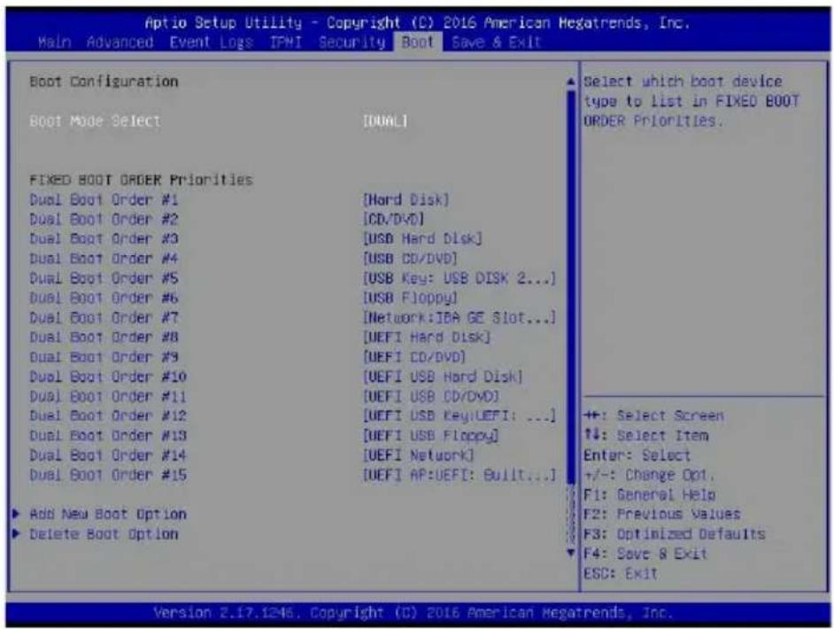
text_image
Aptio Setup Utility - Copyright (C) 2016 American Megatrends, Inc. Main Advanced Event Logs IPMI Security Boot Save & Exit Boot Configuration Boot Mode Select [DUAL] FIXED BOOT ORDER Priorities Dual Boot Order #1 [Hard Disk] Dual Boot Order #2 [CD/DVD] Dual Boot Order #3 [USB Hard Disk] Dual Boot Order #4 [USB CD/DVD] Dual Boot Order #5 [USB Key: USB DISK 2...] Dual Boot Order #6 [USB Floppy] Dual Boot Order #7 [Network: IBA GE Slot...] Dual Boot Order #8 [UEFI Hard Disk] Dual Boot Order #9 [UEFI CD/DVD] Dual Boot Order #10 [UEFI USB Hard Disk] Dual Boot Order #11 [UEFI USB CD/DVD] Dual Boot Order #12 [UEFI USB Key:UEFI: ...] Dual Boot Order #13 [UEFI USB Floppy] Dual Boot Order #14 [UEFI Network] Dual Boot Order #15 [UEFI AP:UEFI: Built...] Add New Boot Option Delete Boot Option Select which boot device type to list in FIXED BOOT ORDER Priorities. +: Select Screen +: Select Item Enter: Select +/-: Change Opt. F1: General Help F2: Previous Values F3: Optimized Defaults F4: Save & Exit ESC: Exit. Version 2.17.12-46. Copyright (C) 2016 American Megatrends, Inc.Boot Mode Select
Use this item to select the type of device that the system is going to boot from. The options are Legacy, UEFI, and Dual. The default setting is Dual.
Fixed Boot Order Priorities
This option prioritizes the order of bootable devices that the system to boot from. Press
- Dual Boot Order #1
- Dual Boot Order #2
• Dual Boot Order #3 - Dual Boot Order #4
- Dual Boot Order #5
• Dual Boot Order #6 - Dual Boot Order #7
• Dual Boot Order #8
• Dual Boot Order #9
• Dual Boot Order #10
• Dual Boot Order #11
• Dual Boot Order #12
• Dual Boot Order #13
• Dual Boot Order #14
• Dual Boot Order #15
▶ Delete Boot Option
Use this feature to remove a pre-defined boot device from which the system will boot during startup.
The settings are [any pre-defined boot device].
▶ NETWORK Drive BBS Priorities
This feature allows the user to specify which Network devices are boot devices.
• Legacy Boot Order #1
- 2nd Boot Device
▶UEFI Application Boot Priorities
This feature allows the user to specify which UEFI devices are boot devices.
• UEFI Boot Order #1
7-8 Save & Exit
Select the Exit tab from the BIOS setup utility screen to enter the Exit BIOS Setup screen.

text_image
Aptio Setup Utility - Copyright (C) 2016 American Megatrends, Inc. Main Advanced Event Logs IPMI Security Boot Save & Exit Discard Changes and Exit Save Changes and Reset Save Options Save Changes Discard Changes Restore Optimized Defaults Save as User Defaults Restore User Defaults Boot Override UEFI: Built-in EFI Shell IBA GE Slot 0700 v1578 Exit system setup without saving any changes. +: Select Screen T#: Select Item Enter: Select +/-: Change Opt. F1: General Help F2: Previous Values F3: Optimized Defaults F4: Save & Exit ESC: Exit Version 2.17.1245. Copyright (C) 2016 American Mega Trends, Inc.Discard Changes and Exit
Select this option to quit the BIOS Setup without making any permanent changes to the system configuration, and reboot the computer. Select Discard Changes and Exit from the Exit menu and press
Save Changes and Reset
When you have completed the system configuration changes, select this option to leave the BIOS setup utility and reboot the computer, so the new system configuration parameters can take effect. Select Save Changes and Exit from the Exit menu and press
Save Options
Save Changes
After completing the system configuration changes, select this option to save the changes you have made. This will not reset (reboot) the system.
Discard Changes
Select this option and press
Restore Defaults
To set this feature, select Restore Defaults from the Save & Exit menu and press
Save As User Defaults
To set this feature, select Save as User Defaults from the Exit menu and press
To set this feature, select Restore User Defaults from the Exit menu and press
Boot Override
Listed on this section are other boot options for the system (i.e., Built-in EFI shell). Select an option and press
Notes
Appendix A
BIOS Error Beep Codes
During the POST (Power-On Self-Test) routines, which are performed upon each system boot, errors may occur.
Non-fatal errors are those which, in most cases, allow the system to continue to boot. These error messages normally appear on the screen.
Fatal errors will not allow the system to continue with bootup. If a fatal error occurs, you should consult with your system manufacturer for possible repairs.
These fatal errors are usually communicated through a series of audible beeps. The numbers on the fatal error list correspond to the number of beeps for the corresponding error.
Note: A PC buzzer must be connected to JD1 to hear the BIOS Error Beep Codes.
| BIOS Error Beep Codes | ||
| Beep Code/LED Error Message Description | ||
| 1 beep Refresh Circuits have been reset. | (Ready to power up) | |
| 5 short beeps + 1 long beep | Memory error No memory detected in the system | |
| 8 beeps Display memory | read/write error | Video adapter missing or with faulty memory |
| OH LED On System OH System Overheat | ||
Notes
Appendix B
System Specifications
Processor
Single Intel® Xeon/Pentium® D-1500 Family SoC embedded processor (SoC = System on a Chip
BIOS
128 Mb AMI® SPI Flash EEPROM
Memory Capacity
Four SO-DIMM slots that can support up to 128 GB of ECC RDIMM (Registered DIMM) or 64 GB of ECC/non-ECC UDIMM (Unregistered DIMM) DDR4-2133/1866/1600 memory
Note: see Section 5-5 for details.
Hard Drives
Twelve 3.5" internal SATA hard drives
Motherboard
5018D2-AR12L: X10SDV-2C-7TP4F (Flex ATX form factor)
5018D4-AR12L: X10SDV-4C-7TP4F (Flex ATX form factor)
5018D8-AR12L: X10SDV-7TP4F (Flex ATX form factor)
Dimensions: 9 x 7.25 in (229 x 184 mm)
Chassis
SC801LTS-R406P (1U rackmount)
Dimensions: (WxHxD) 17.2 x 1.7 x 32 in. (437 x 43 x 813 mm)
Weight
38 lbs. (17.3 kg.)
System Input Requirements
AC Input Voltage: 100 - 240V AC auto-range
Rated Input Current: 6-3A
Rated Input Frequency: 50 to 60 Hz
Power Supply
Rated Output Power: 400W (Part# PWS-406P-1R)
Rated Output Voltages: +5V (25A), +12V (33A), -12V (0.6A), +3.3V (25A), +5Vsb (3A)
Operating Environment
Operating Temperature: 10^ to 35^ C ( 50^ to 95^ F)
Non-operating Temperature: -40^ to 70^ C ( -40^ to 158^ F)
Operating Relative Humidity: 8% to 90% (non-condensing)
Non-operating Relative Humidity: 5% to 95% (non-condensing)
Regulatory Compliance
Electromagnetic Emissions: FCC Class A, EN 55022 Class A, EN 61000-3-2/-3-3, CISPR 22 Class A
Electromagnetic Immunity: EN 55024/CISPR 24, (EN 61000-4-2, EN 61000-4-3, EN 61000-4-4, EN 61000-4-5, EN 61000-4-6, EN 61000-4-8, EN 61000-4-11)
Safety: CSA/EN/IEC/UL 60950-1 Compliant, UL or CSA Listed (USA and Canada), CE Marking (Europe)
California Best Management Practices Regulations for Perchlorate Materials:
This Perchlorate warning applies only to products containing CR (Manganese Dioxide) Lithium coin cells. "Perchlorate Material-special handling may apply. See www.dtsc.ca.gov/hazardouswaste/perchlorate"
Notes
(continued from front)
The products sold by Supermicro are not intended for and will not be used in life support systems, medical equipment, nuclear facilities or systems, aircraft, aircraft devices, aircraft/emergency communication devices or other critical systems whose failure to perform be reasonably expected to result in significant injury or loss of life or catastrophic property damage. Accordingly, Supermicro disclaims any and all liability, and should buyer use or sell such products for use in such ultra-hazardous applications, it does so entirely at its own risk. Furthermore, buyer agrees to fully indemnify, defend and hold Supermicro harmless for and against any and all claims, demands, actions, litigation, and proceedings of any kind arising out of or related to such ultra-hazardous use or sale.