J1627T4 - Heating Hubbell - Free user manual and instructions
Find the device manual for free J1627T4 Hubbell in PDF.

User questions about J1627T4 Hubbell
0 question about this device. Answer the ones you know or ask your own.
Ask a new question about this device
Download the instructions for your Heating in PDF format for free! Find your manual J1627T4 - Hubbell and take your electronic device back in hand. On this page are published all the documents necessary for the use of your device. J1627T4 by Hubbell.
USER MANUAL J1627T4 Hubbell
Commercial Food Equipment Service Association

NAFEM
North American Association of Food Equipment Manufacturers
Manufacturers' Agents for the Food Service Industry
ISO 9001:2008 ISO
UM
ANSI/NSF5
2017 Edition
HUBBELL
ELECTRIC HEATER COMPANY
45 SEYMOUR STREET
P.O. BOX 288
STRATFORD, CT 06615
PHONE: (203) 378-2659
FAX: (203) 378-3593
INTERNET: http://www.hubbellheaters.com
-- IMPORTANT --
Always reference the full model number and serial number when calling the factory.
WARNING / CAUTION
- Tank is to be completely filled with water and all air is to be vented before energizing.
- Due to the rigors of transportation, all connections should be checked for tightness before heater is placed in operation.
-
Safety relief valve must be installed in tapping provided.
-
The refractory material used in heating elements may absorb some moisture during transit, periods of storage, or when subjected to a humid environment. This moisture absorption results in a cold insulation resistance of less than one (1) megohms. If this heater has been subjected to the above condition, each heating element must be checked for insulation resistance before energizing. Contact the factory for a replacement element.
-
KEEP AWAY FROM LIVE ELECTRICAL CIRCUITS.
Do not perform any maintenance, make any adjustments, or replace any components inside the control panel with the high voltage power supply turned on. Under certain circumstances, dangerous potentials may exist even when the power supply is off. To avoid casualties, always turn the power supply safety switch to off, turn the charge or ground the circuit before performing any maintenance or adjustment procedure.
-
The unit is designed to operate at pressure not more than 150 psi.
-
Generalized instructions and procedures cannot anticipate all situations. For this reason, only qualified installers should perform the installations. A qualified installer is a person who has licensed training and a working knowledge of the applicable codes, tools, equipment, and methods necessary for safe installation of an electric resistance water heater. If questions regarding installation arise, check your local plumbing and electrical inspectors for proper procedures and codes. If you cannot obtain the required information, contact the company.
-
Water Quality Requirements – Recommended water hardness is 4 to 6 grains of hardness per gallon (GPG). Water hardness above 6 GPG should be treated by a water conditioner (water softener or in-line treatment). Water hardness below 4 GPG also requires treatment to reduce potential corrosion. Excessive GPG will result in higher operating and maintenance costs and will reduce product longevity. Chlorides must not exceed 50 parts per million (ppm). Excessive chlorides will result in metallic corrosion and will reduce product longevity. Water treatment has been shown to reduce costs associated with de-liming the booster as well as reducing metallic corrosion. Product failure caused by these conditions is not covered under warranty. See warranty for complete details.
-
This water heater is not intended for space heating applications.
-
The water heater is factory set at 185^ F for booster water heating applications. This results in the possibility of a scalding water injury. A full thickness skin burn can occur in less than one second of exposure to water at this temperature.
TABLE OF CONTENTS
SECTION TITLE
PAGE No.
I GENERAL DESCRIPTION AND CONSTRUCTION 4
II INSTALLATION AND START-UP 9
III SCHEDULED MAINTENANCE AND OPERATION 24
IV TROUBLESHOOTING 26
V SERVICING AND REPLACEMENT OF PARTS 32
VI SERVICE PARTS LIST 35
VII TORQUE VALUES 37
VIII WARRANTY INFORMATION 38
SECTION I - GENERAL DESCRIPTION AND CONSTRUCTION
GENERAL DESCRIPTION
This book describes a packaged electric booster heater that is typically used to provide 180^ F sanitizing rinse water. The complete assembly consists of the storage tank, immersion electric heating element(s), electronic control module, safety relief valve, magnetic contactor(s), and any other required electrical operating control. Optional equipment may be supplied with your unit. Please consult the product packing list for details specific to your assembly. The unit is factory assembled, insulated, jacketed, wired, tested, and ready for electrical and plumbing service connections.
CAPACITY
| Model | Storage Capacity(gallons) | kW | 40°F Rise(GPH) | 70°F Rise(GPH) | 9 9 | Model | Storage Capacity(gallons) | kW | 40°F Rise(GPH) | 70°F Rise(GPH) |
| J32.9 3 | 2.9 30 17 J | 61 16 1 1 | 0 5 | |||||||
| J35.7 3 | 5.7 58 33 J | 61.5 16 1 | .5 15 8 | |||||||
| J39.9 3 | 9.9 101 58 | J162 16 2 | 20 11 | |||||||
| J310.4 3 | 10.4 | 07 61 J16 | 3 16 3 30 | 17 | ||||||
| J311.4 3 | 11.4 | 17 67 J16 | 4 16 4 41 | 23 | ||||||
| J411 | 4 11.4 | 117 | 67 J166 1 | 6 6 62 35 | ||||||
| J415 | 4 15 1 | 54 88 J16 | 7 16 7 72 | 41 | ||||||
| J427 | 4 27 2 | 77 1 | 58 | J169 16 | 9 9 | 2 53 | ||||
| J61 | 6 | 1 | 10 | 5 | J1612 | 16 | 12 | 123 | 70 | |
| J61.5 6 | 1.5 15 8 J16 | 613 | 16 13.5 | 138 79 | ||||||
| J62 | 6 | 2 | 20 | 11 | J1615 | 16 | 15 | 154 | 88 | |
| J63 | 6 | 3 | 30 | 17 | J1618 | 16 | 18 | 185 | 105 | |
| J64 | 6 | 4 | 41 | 23 | J1624 | 16 | 24 | 246 | 141 | |
| J65 | 6 | 5 | 51 | 29 | J1627 | 16 | 27 | 277 | 158 | |
| J66 | 6 | 6 | 62 | 35 | J1630 | 16 | 30 | 308 | 176 | |
| J67 | 6 | 7 | 72 | 41 | J1636 | 16 | 36 | 369 | 211 | |
| J69 | 6 | 9 | 92 | 53 | J1639 | 16 | 39 | 400 | 228 | |
| J610 | 6 | 10.5 | 108 | 62 | J1640 | 16 | 40.5 | 415 | 237 | |
| J612 | 6 | 12 | 123 | 70 | J1645 | 16 | 45 | 461 | 264 | |
| J613 | 6 | 13.5 | 138 | 79 | J1654 | 16 | 54 | 554 | 316 | |
| J615 | 6 | 15 | 154 | 88 | J1658 | 16 | 58.5 | 600 | 343 | |
| J618 | 6 | 18 | 185 | 105 | J1664 | 16 | 64 | 656 | 375 | |
| J624 | 6 | 24 | 246 | 141 | J1666 | 16 | 66 | 677 | 387 | |
| J627 | 6 | 27 | 277 | 158 | J1668 | 16 | 68 | 697 | 398 | |
| J630 | 6 | 30 | 308 | 176 | J1679 | 16 | 79 | 810 | 463 | |
| J636 | 6 | 36 | 369 | 211 | J1681 | 16 | 81 | 830 | 474 | |
| J639 | 6 | 39 | 400 | 228 | J1685 | 16 | 85 | 871 | 498 | |
| J640 | 6 | 40.5 | 415 | 237 | J1686 | 16 | 86 | 882 | 504 | |
| J645 | 6 | 45 | 461 | 264 | J1688 | 16 | 88 | 902 | 515 | |
| J654 | 6 | 54 | 554 | 316 | J1690 | 16 | 90 | 923 | 527 | |
| J658 | 6 58.5 | 600 | 343 |
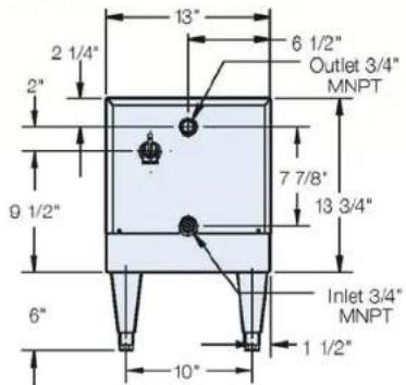
Model (J6) - (1 to 18kW) Dimensions

natural_image
Exterior view of a white industrial device with four black legs and a control panel (no visible text or symbols)Shipping Weight: 95 lbs.
text_image
13" 2 1/4" 6 1/2" Outlet 3/4" MNPT 7 7/8" 13 3/4" 9 1/2" 6" Inlet 3/4" MNPT 1 1/2" 10"Rear View

text_image
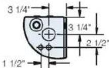
25° Approx. 21" Relief 14 1/8" 5 3/8" 2 1/2"Left Side View
Knockouts: Left Side And Bottom 3/4" X 1" X 1-1/4"

Bottom View
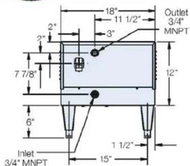
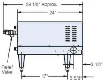
Model (J6) - (24 to 58.5 kW) Dimensions

natural_image
Exterior view of a stainless steel industrial appliance with four legs and control knobs (no visible text or symbols)Shipping Weight: 110 lbs.
text_image
18" 11 1/2" 3" 7 7/8" 6" Inlet 3/4" MNPT 1 1/2" 15" Outlet 3/4" MNPT 12"Rear View
text_image
29 1/8" Approx. 24" 3 1/4" 17" 5 5/8"Left Side View
Knockouts: Left Side - (1) 1-1/2" X 2"
Bottom - (2) 1/2" and (1) 1-1/2" x 2"
Bottom View
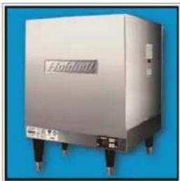
Model J16 - (1 to 58.5 kW) Dimensions
natural_image
Exterior view of a stainless steel industrial appliance with control knobs and a label (no readable text or symbols beyond branding)Shipping Weight: 160 lbs.

text_image
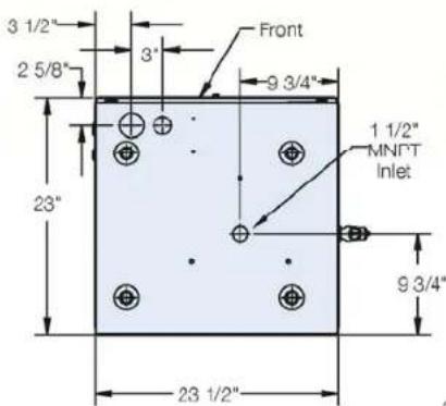
3 1/2" 2 5/8" 23" 3" 9 3/4" 3/4" MNPT Inlet 3/4" M Ou Nip 9 3/4" 2" 23 1/2"Bottom View
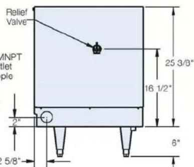
text_image
Relief Valve MNPT tlet ple 2" 2 5/8" 6" 16 1/2" 25 3/8"Right Side View
Knockouts: Left Side - 1-1/2" X 2"
Bottom - 1-1/2" X 2" and 3/4" X 1" X 1-1/4"
Model (J16) - (64 to 88 kW) Dimensions

natural_image
Exterior view of a stainless steel industrial machine (no visible text or symbols)Shipping Weight: 195 lbs.
text_image
3 1/2" 2 5/8" 23" 3' 9 3/4" Front 1 1/2" MNFT Inlet 9 3/4" 23 1/2"Bottom View
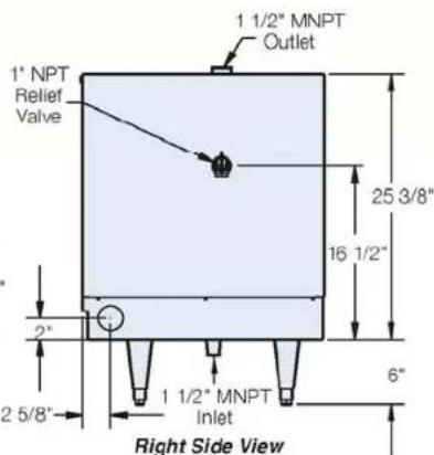
text_image
1 1/2" MNPT Outlet 1" NPT Relief Valve 25 3/8" 16 1/2" 2" 2 5/8" 1 1/2" MNPT Inlet 6" Right Side ViewKnockouts: Left Side - 1-1/2" X 2"
Bottom - 1-1/2" X 2" and 3/4" X 1" X 1-1/4"
Model J3 - (2.9 to 11.4 kW) Dimensions
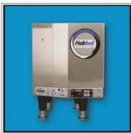
natural_image
Exterior view of a Huawei air conditioner unit (no visible text or symbols on the device body)Shipping Weight: 46 lbs.
Note: Shown with optional legs
text_image
12 1/2" 6" Relief Valve 9" 3/4" FFront View

text_image
13 1/4" 3/8" 11 3/4" 5 1/2" 3/8" 3" 4 7/8" 5 7/8" 13" 4 1/2" Ø 5/16" Mounting Holes (4 Places) NPT Outlet Top View
text_image
1/2" (0.84) KO 3/4" FNPT Inlet 4 1/4" 1 1/4" 1 1/2" 1/2" 1" × 3/4" × 1/2" knockoutBottom View
Model (J4) - (11.4 to 27 kW) Dimensions
natural_image
Exterior view of a white fluidic acid container unit with control panel (no visible text or symbols)Shipping Weight: 80 lbs.
Note: Shown with optional legs
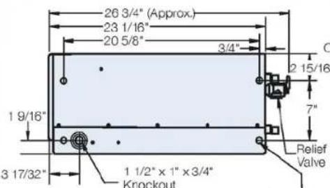
text_image
26 3/4" (Approx.) 23 1/16" 20 5/8" 3/4" 1 9/16" 3 17/32" 1 1/2" x 1" x 3/4" Knockout 2 15/16" 7" Relief ValveRight Side View
text_image
10 13/16" 2 1/4" b 13/32" Outlet 3/4" MNPT 1 1/8" 6" 11 7/16" 2 3/4" Inlet 3/4" MNPTRear View

Bottom View
Hubbell™
CONSTRUCTION
TANK
The storage tank is designed, manufactured, and stamped in accordance with ASME Section VIII, Division 1. The tank is constructed of type 304L stainless steel for maximum tank longevity and fabricated by all welded construction and is designed for a maximum allowable working pressure of 150 psi (225 psi test pressure).
TANK CONNECTIONS
The heater is supplied with separate connections for the cold/warm inlet and the hot water outlet. Water entering the warm water inlet and leaving through the hot water outlet is evenly circulated by means of a diffuser within the tank. A 34 -inch FNPT connection is provided for mounting a combination temperature and pressure safety relief valve. An overflow line should be utilized from the relief valve outlet to a floor drain. See drawing for locations and sizes.
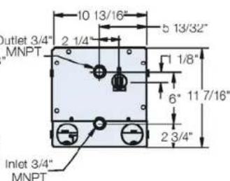
HEATING ELEMENT
The water heater is supplied with an electric immersion heating element assembly(s), composed of corrosion resistant sheathed elements that are fitted into a 1½-12UNF brass screw plug with a 1 ^7/8 " hex. Each assembly is threaded into the tank and sealed with an o-ring gasket. See drawing for voltage and power ratings. Note that the J3 model element is a 1" NPS thread with a 1 ^1/2 " hex.
natural_image
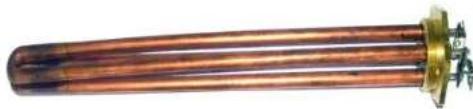
Close-up of a copper heating element with a brass end cap and metallic fittings (no visible text or symbols)MAGNETIC CONTACTOR
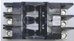
Load switching is done by a heavy-duty resistive (non-inductive) load type definite purpose magnetic contactor. The contactor supplies power to the heating element(s) when the relay on the control board is closed, thereby pulling in the contacts until the desired temperature is reached. At this point, the contacts will drop out, which in turn disconnects power from the elements. Units with multiple contactors will turn on and off in stages. This contactor is good for 200,000 cycl
natural_image
Close-up of an electrical contactor component with no visible text or symbolsCONTROL BOARD AND DISPLAY
The control board supplies all the necessary functions for heater operation. These include control temperature, hi-limit cut-out, low water detection, and leak detection.

natural_image
Two electronic components: a digital display module and a circuit board with visible traces (no text or symbols)LOW VOLTAGE CONTROL TRANSFORMER
A control circuit transformer is supplied with all models rated greater than 240-volts. This component is used to step down the primary power supply (600, 480, 440, 415, 380, or 277) to 208/240-volts for safety when working with control.

When required by code, a magnetic power circuit breaker is supplied for circuit overload protection. The circuit breaker can be reset in the event of a current overload.
OUTER SHELL, INSULATION, AND SUPPORTS
The tank is encapsulated in high efficiency foam insulation meeting the requirements for UL 94 HF-1 rating. The protective shell is constructed of type 304 brushed stainless steel. NSF approved adjustable plastic legs are provided for support. Plastic legs for the J3 and J4 models are optional.
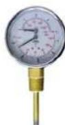
DIAL TEMPERATURE AND PRESSURE GAUGE
A combination temperature (30°-240° F / 0°-120°C) and pressure (0–200 psi / 0-1400 kPa) gauge with 3-inch dial is supplied with the unit for in-line installation (shipped loose). The connection is 12 " NPT with a 2" long sensing probe. For the J3 and J4 models the gauges are optional.
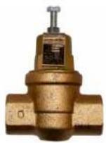
STANDARD PRESSURE REDUCING VALVE
A pressure reducing valve with built-in bypass is supplied with the unit. This valve is shipped separately for in-line installation. The standard PRV has internal 34 " female NPT threading and is adjustable from 10psi to 70 psi and is preset to 25psi. The set screw located at the top of the diaphragm adjusts the pressure, turn clockwise to increase the pressure and counter-clockwise to decrease the pressure. Pressure reducing valves for the J3 and J4 models are optional.
OPTIONAL EQUIPMENT (not available on J4 Models)
Slide Brackets
Available for the J6 Model only, these brackets allow for mounting the booster heater under a counter. See slide bracket diagram on page 9 for details.
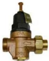
Brass Pressure Reducing Valve
The optional brass pressure reducing valve with built-in bypass is shipped separately for in-line installation. The inlet connection is supplied with a 34 " union by sweat connection. The outlet is 34 " female NPT. The 34 " NPT valve is adjustable from 25psi-75psi (approx. 17psi to 67psi including pressure drop through the valve). The brass PRV is preset to 50psi and must be adjusted to 25psi. The set screw located at the top of the diaphragm adjusts the pressure, turn clockwise to increase the pressure and counter-clockwise to decrease the pressure. Pressure reducing valves for the J3 and J4 models are optional.
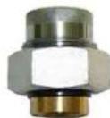
Dielectric Unions
Dielectric unions are provided for the inlet and outlet nipples to isolate stray ground currents to reduce the possibility of galvanic corrosion. (Optional on the J3 and J4 Models).
Shock Absorber
The optional shock absorber can be installed between the booster and the dishwasher to reduce the harmful pressures resulting from quick closing dishwasher solenoid valves.

Legs
In lieu of the standard black plastic legs, optional adjustable legs are available in stainless steel, die-cast nickel plated, and floor mount stainless steel. All optional legs are adjustable height type.
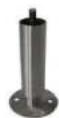
Floor Mount
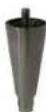
Nickel Plated
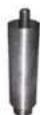
Stainless Steel
Security Package
For prison and other secure facilities a tamper resistant package is available. All external screws are spader type requiring a spader wrench for removal.
Alternate Voltage
Other voltages are available, including 277V single-phase, and 380V, 415V, and 440V three-phase. Consult the factory for details.
Water Treatment System
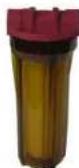
The optional water treatment system provides superior mineral scale prevention and corrosion control by feeding a special blend of scale control compounds into the warm water stream before the heater. The in-line system includes a clear cartridge housing to allow an operator to view the cartridge and determine when it needs replacement without the need to open the system.
XB1 Expansion Board
An optional expansion board to the control board can be used to for additional circuit firing when more than two circuits are required and/or as an auxiliary high or low temperature alarm/relay. On models with three contactors the XB1 is supplied as standard.
Remote Alarm Plug Adapter
An optional plug adapter is available to provide a remote fault alarm signal through the J4 connector on the control board. See page 12 for installation details.

An optional plug adapter is available to interlock the heater via a 24-volt signal through the J1 connector on the control board. The 24-volt heater interlock adapter is supplied standard on the J3 model. See page 13 for installation details. (Only available with r23 or later software).

Protective Shrouds (J6 and J16 only)
An optional durable protective plastic shroud is available to prevent damage to the booster due to water intrusion. The cover fits snugly over the entire booster and can be easily removed for cleaning and service.
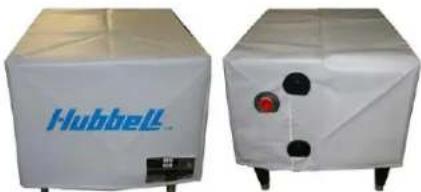
natural_image
Two white industrial equipment cases with visible branding, one labeled 'Hubbell' and the other with a red button (no text or symbols on the equipment itself)SECTION II – INSTALLATION AND START-UP
WARNING / CAUTION
- DO NOT TURN ON THE ELECTRIC POWER SUPPLY to this equipment until heater is completely filled with water and all air has been released. If the heater is NOT filled with water when the power is turned on, the heating elements will burn out.
- For protection against excessive pressures and temperatures, local codes require the installation of a temperature-and-pressure (T&P) relief valve certified by a nationally recognized laboratory that maintains periodic inspection of production of listed equipment of materials, as meeting the requirements for Relief Valves and Automatic Gas Shutoff for Hot Water Supply Systems. ANSI Z21.22-1971. THE CUSTOMER IS RESPONSIBLE TO PROTECT PROPERTY AND PERSONNEL FROM HARM WHEN THE VALVE FUNCTIONS.
- All water heaters have a risk of leakage at some unpredictable time. IT IS THE CUSTOMER'S RESPONSIBILITY TO PROVIDE A CATCH PAN OR OTHER ADEQUATE MEANS, SO THAT THE RESULTANT FLOW OF WATER WILL NOT DAMAGE FURNISHINGS OR PROPERTY.
- Installation or service of this unit requires ability equal to that of a licensed tradesman in the field.
- The installation must conform to these instructions and any local authority having jurisdiction. Grounding and electrical wiring connected to the unit must also conform to the latest version of the National Electric Code NFPA-70.
WATER HEATER PLACEMENT
NOTE: For most effective operation, install the booster heater as close as possible to the dishwasher. If the distance between the booster and the dishwasher exceeds NSF requirements, recirculation methods must be employed.
-
Place the heater on a solid, level foundation in a clean, dry location as near as possible to the dish washing machine.
-
The water heater should be protected from freezing and waterlines insulated to reduce energy and water waste.
-
Leave a minimum of 18" clearance for element withdrawal and control access.
-
Do not install in an area where flammable liquids or combustible vapors are present.
SLIDE BRACKETS FOR HANGING SUPPORT MOUNTING
- Weld slide rails to bottom of dishtable. Spacing should be 17" for J6 models up to 18kW and 22" for J6 models 24 to 58.5kW. J16 models are not designed for use with slide brackets.

text_image
A= 17" FOR J6 1 TO 18 KW 22" FOR J6 24 TO 58.5 KW WELD SLIDE RAIL TO BOTTOM OF DISHTABLE ATTACH SLIDE BRACKET ANGLE TO HEATER JACKET-
Attach slide bracket angles to heater with #8 sheet metal screws. It will be necessary to drill 1/8" holes into heater jacket for screw pilot holes.
-
Slide heater onto slide rails under dishtable.
PIPING INSTALLATION - See Diagrams
NOTES:
- No check valve may be installed in the supply line to the booster.
- All shut-off valves must be gate or ball valves – not globe valves.
- To minimize heat loss and maximize efficiency, hot water piping should be insulated.
-
Teflon tape should be used on all NPT threaded pipe connections.
-
Install the optional dielectric unions on the inlet and outlet piping.
-
Connect the cold/warm water inlet and hot water outlet to the appropriate connections as shown; refer to the specifications for location and sizes.
IMPORTANT – Be certain to connect the outlet piping to the final rinse and not to the wash tank. Insulate if over 3 feet.
IMPORTANT (applies to J6 Models only) – Do not turn the entering warm water or exiting hot water nipples from their factory installed positions. The internal diffusers are aligned at the factory and turning the nipple will change the diffuser position and affect performance. Hubbell recommends that the inlet and outlet pipes are insulated to prevent excessive heat loss.
IMPORTANT (applies to J6 Models only) – Do not apply heat directly to the entering warm water or exiting hot water nipples. If sweat connections are to be used, sweat tubing to the adapter before threading the adapter to the nipple on the heater. Any heat applied to the heater nipple will damage the internal plastic diffuser and affect performance.
- Install the pressure reducing valve in the entering cold/warm water inlet line and adjust to 20-psi. The standard PRV comes preset to 25psi. The optional brass PRV is preset to 50psi and must be adjusted to 25psi. The set screw located at the top of the diaphragm adjusts the pressure, turn clockwise to increase the pressure and counterclockwise to decrease the pressure. NOTE: Be sure to install the valve with flow in the proper direction as indicated by the directional arrow on the valve. IF A STANDARD PRESSURE REGULATOR IS USED, it acts as a check valve and it is possible that thermal expansion will cause the relief valve to drip or occasionally blow off a small amount of water. To overcome this condition, it is recommended that a 3/8" by-pass arrangement with a horizontal check valve be installed around the pressure regulator. This will prevent annoyance caused by the relief valve dripping or blowing off.
NOTE: It is strongly recommended that a pressure reducing valve with built-in bypass is installed in models where one is not supplied.
- Install the combination temperature and pressure safety relief valve in the tapping provided. Note that this is required by law for safety considerations.
Install into provided tapping Manual Release Lever
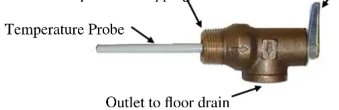
text_image
Temperature Probe Outlet to floor drain- Install a relief valve overflow pipe to a nearby floor drain.
NOTE: Relief valve discharge piping limitations:
a. Termination to be plain end (no threads) and 6-inches above the drain.
b. Maximum 30-feet.
c. Maximum four (4) elbows.
d. No reduction in line size.
e. No valve of any type to be installed between the relief valve and tank or in the drain line.
-
A shock absorber is recommended in the hot water outlet line to soften the water hammer caused by automatic dishwasher solenoid valves.
-
Install the in-line pressure and temperature gauge, when supplied, in the entering cold/warm water line. If supplied, install the optional second dial temperature and pressure gauge in the outlet line. The temperature sensing element must be in the hot water stream and the gauge must be mounted upright.
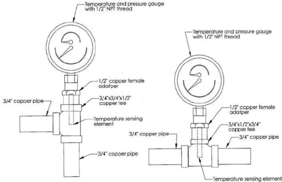
text_image
Temperature and pressure gauge with 1/2" NPT thread 1/2" copper female adatper 3/4"x3/4"x1/2" copper tee Temperature sensing element 3/4" copper pipe 3/4" copper pipe Temperature sensing element Temperature and pressure gauge with 1/2" NPT thread 1/2" copper female adatper 3/4"x1/2"x3/4" copper tee 3/4" copper pipe Temperature sensing elementFILLING THE HEATER
- Open the valve to the cold/warm water inlet and allow the heater and piping system to completely fill, as indicated by a steady flow of water through the dishwasher rinse nozzles.
NOTE: Flush the tank at full flow for 10 minutes prior to putting into service.
ELECTRICAL INSTALLATION
-
Enter the base through the factory cut KO's with properly sized feeder leads, See Wiring Chart. Single-phase installations require two (2) leads. All Hubbell 3-phase heaters are intended for use with a 3-wire delta system plus ground. No neutral is required. For a 4-wire plus ground system, install 3 legs of power plus the ground and terminate the neutral leg.
-
Install these power leads into the box lugs on the power distribution block or magnetic contactor, as required.
-
Connect incoming ground wire to ground lug supplied.
-
Check for proper grounding. Check for AC millivolts (mV) between the ground connection at the booster and the inlet piping past the optional dielectric union (on the building side, not the booster side). There should be zero potential/millivolts (mV). If not zero, then the piping should be re-grounded.
-
All other electrical connections are made at the factory; therefore, no other electrical connections are necessary.
-
Check all connections, including factory connections, for tightness.
OPTIONAL XB1 EXPANSION BOARD (used for temperature alarm / interlock)
-
If desired, the XB1 can be used as an alarm relay or a temperature interlock at a setpoint other than the water temperature setpoint on the booster heater.
-
If the XB1 is not factory installed, mount the XB1 to the control panel and connect the XB1 to the T1000 control board with the factory supplied cable between JX4 on the XB1 and J1 and J4 on the T1000 and connect the ground between JX6 on the XB1 and J8 on the T1000.
-
Make connections as required to the relay term inal block. When the temperature drops below the XB1 setpoint the relay is open between Normally Open (NO) and Common
(C) and the LED will flash green. When the temperature is above the XB1 setpoint the relay is closed between NO and C and the LED will be solid green. Use NO and C for low temperature interlock or high temperature alarm. Use Normally Closed (NC) and C for low temperature alarm. A red LED indicates an error.

text_image
Note: Alarm Rating (resistive): Max.: 5A @ 120VAC 5 A @ 24 V DC (JX6) Ground (JX4) Connection to T1000 (JX5 L1) Power Wire (Common, White) (JX5 L2)Power Wire (Black) (JX5) (4) Connections for Additional Circuit Firing (JX2) Low Temp. Relay Terminal Block (JX3) To be used as T1000 J1 Connection (JX1) To be used as T1000 J4 Connection LEDNote: Once the XB1 is connected to the T1000 control board, an additional menu option will be available to set the low temperature setpoint. See Section III.
FOR REMOTE ON/OFF CONTROL
To remotely control the On / Off operation of the heater, it is recommended that a DPST switch or relay (by others) be used to break both power legs (white and black wires) connected to the top two terminals of the J5 connector on the control board. See diagram at right.
Use a NC (Normally Closed) relay to turn the booster ON when energizing the relay coil or to turn the booster OFF when de-energizing the relay coil.
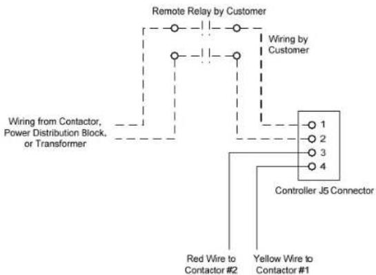
flowchart
graph TD
    A["Remote Relay by Customer"] --> B["Wiring by Customer"]
    B --> C["Controller J5 Connector"]
    C --> D["Red Wire to Contactor #2"]
    C --> E["Yellow Wire to Contactor #1"]
    F["Wiring from Contactor, Power Distribution Block, or Transformer"] --> A
    G["Top line"] --> A
    H["Bottom line"] --> C
Use a NO (Normally Open) relay to turn the booster OFF when energizing the relay coil or to turn the booster ON when de-energizing the relay coil.
OPTIONAL REMOTE ALARM CONTACTS
- If desired, the control board can be wired to a remote alarm to indicate a reset fault condition. These fault conditions include over-temperature, no probe, and low water (when the configuration is set to manual reset).
- This alarm can be wired to the J4 connector on the control board as shown below. To facilitate this installation, an optional adapter, Hubbell P/N PLUG ADAPTER J4, can be purchased to provide wire connections.

text_image
J4 Connector PLUG ADAPTER J4 Note: Rating (resistive) Max. Switching Power: 60W, 62.5VA Max. Switching Voltage: 220VDC, 250VAC Max. Switching Current: 2A Max. Carrying Current: 3A Common (NO) (NC)Note: That when the XB1 expansion board is used, the J4 PLUG ADAPTER should plug into the JX1 connection on the XB1.
OPTIONAL FIELD CONVERSION FROM SINGLE TO THREE PHASE OR THREE TO SINGLE PHASE (J6 and J16 models in 6, 7, and 9 kW at 208 and 240 volts and J411 models only)
- Re-wire the unit to desired configuration as indicated below.
NOTE: The wire to be used for internal wiring must conform to SEW-2 or PTFE (200°C) and must match the wire size currently in use. Contact the factory for assistance, if required.
- Contact the factory for correct labels. The factory will need the serial number for proper identification.
-
If desired, the heater can be wired to operate only when supplied with a 24-volt signal through the heater interlock adapter. When no 24-volt signal is supplied through the heater interlock adapter the heater is interlocked and will not energize. When interlocked the display will show "III.d". The heater will resume normal operation when a 24-volt signal is re-applied through the heater interlock adapter.
-
To utilize this feature, plug the 24-volt heater interlock adapter into terminal J1 of the T1000 control board (note: if the XB1 expansion board is used, plug the adapter into terminal JX3 of the XB1) and verify that the configuration is set to "Hon", see the controller operation section for further detail. The signal can be either AC or DC. However, if a DC signal is utilized and the interlock feature does not operate, switch the two 24-volt supply wires at the heater interlock adapter.

natural_image
Green printed circuit board with various electronic components and a labeled component 'J1' (no readable text or symbols beyond label)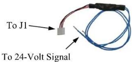
text_image
To J1 To 24-Volt SignalFINAL CHECKS
- Check all connections for tightness.
- Ensure that all the above steps are com pleted.
- Remove the protective outer plastic covering from the sheet metal shell.
- After the water is heated for the first time, monitor the water temperature as described in Section III, Annual Inspection.
J6 and J16 Wiring Chart
| kW Volt Ph | Unit Amp Draw | Branch Amp Draw | Phase-Phase Resistance (Ohms) | Min. Feed Breaker or Fuse Size | Internal Power Wire Size | Element Jumper Wire Size | Copper Power Feed Wire Size | Conduit Size | Diagram | |
| 1 12 | 0 1 8.3 | 8.3 | 14.4 15 | 12 N/A | 14 1⁄2" 1(NT) | |||||
| 1.5 | 120 | 1 | 12.5 | 12.5 | 9.6 | 20 | 12 | N/A | 14 | 1⁄2" |
| 2 | 120 | 1 | 19.8 | 19.8 | 6.1 | 25 | 12 | N/A | 12 | 1⁄2" |
| 3 | 120 | 1 | 25.0 | 25.0 | 4.8 | 35 | 12 | 12 | 10 | 1⁄2" |
| 4 | 208 | 1 | 19.2 | 19.2 | 10.8 | 25 | 12 | N/A | 10 | 1⁄2" |
| 240 | 1 | 16.7 | 16.7 | 14.4 | 25 | 12 | N/A | 12 | 1⁄2" | |
| 380 | 1 | 10.7 | 10.7 | 36.1 | 15 | 12 | N/A | 12 | 1⁄2" | |
| 480 | 1 8.3 | 8.3 57.6 | 15 12 N/A | 14 1⁄2" | 1(WT) | |||||
| 5 | 208 | 1 | 24.0 | 24.0 | 8.7 | 30 | 12 | N/A | 10 | 1⁄2" |
| 240 | 1 | 20.8 | 20.8 | 11.5 | 30 | 12 | N/A | 10 | 1⁄2" | |
| 380 | 1 | 13.2 | 13.2 | 28.9 | 20 | 12 | N/A | 12 | 1⁄2" | |
| 480 | 1 | 10.4 | 10.4 | 46.1 | 15 | 12 | N/A | 14 | 1⁄2" | |
| 6 | 208 | 1 | 28.8 | 28.8 | 7.2 | 40 | 12 | 12 | 8 | 1⁄2" |
| 208 | 3 | 16.7 | 16.7 | 14.4 | 25 | 12 | 12 | 10 | 1⁄2" | |
| 240 | 1 | 25.0 | 25.0 | 9.6 | 35 | 12 | 12 | 8 | 1⁄2" | |
| 240 | 3 | 14.4 | 14.4 | 19.2 | 20 | 12 | 12 | 12 | 1⁄2" | |
| 380 | 3 | 8.6 | 8.6 | 48.1 | 15 | 12 | 12 | 14 | 1⁄2" | |
| 480 | 3 | 7.2 | 7.2 | 76.8 | 10 | 12 | 12 | 14 | 1⁄2" | |
| 600 | 3 | 6.0 | 6.0 | 114.8 | 10 | 12 | 12 | 14 | 1⁄2" | |
| 7 | 208 | 1 | 32.5 | 32.5 | 6.4 | 45 | 12 | 12 | 8 | 1⁄2" |
| 208 | 3 | 18.7 | 18.7 | 12.4 | 25 | 12 | 12 | 10 | 1⁄2" | |
| 240 | 1 | 33.2 | 33.2 | 7.2 | 45 | 12 | 12 | 8 | 1⁄2" | |
| 240 | 3 | 19.2 | 19.2 | 14.4 | 25 | 12 | 12 | 10 | 1⁄2" | |
| 380 | 3 | 10.0 | 10.0 | 41.3 | 15 | 12 | 12 | 12 | 1⁄2" | |
| 480 | 3 | 8.4 | 8.4 | 65.8 | 15 | 12 | 12 | 14 | 1⁄2" | |
| 600 | 3 | 6.8 | 6.8 | 102.0 | 10 | 12 | 12 | 14 | 1⁄2" | |
| 9 | 208 | 1 | 43.3 | 43.3 | 4.8 | 55 | 10 | 10 | 6 | 3⁄4" |
| 208 | 3 | 25.0 | 25.0 | 9.6 | 35 | 10 | 10 | 8 | 1⁄2" | |
| 240 | 1 | 37.5 | 37.5 | 6.4 | 50 | 10 | 10 | 8 | 1⁄2" | |
| 240 | 3 | 21.7 | 21.7 | 12.8 | 30 | 10 | 10 | 10 | 1⁄2" | |
| 380 | 3 | 14.3 | 14.3 | 32.1 | 20 | 12 | 12 | 12 | 1⁄2" | |
| 480 | 3 | 10.8 | 10.8 | 51.2 | 15 | 12 | 12 | 14 | 1⁄2" | |
| 600 | 3 | 9.1 | 9.1 | 76.5 | 15 | 12 | 12 | 14 | 1⁄2" | |
| 10.5 | 208 | 1 | 48.8 | 48.8 | 4.3 | 65 | 8 | 10 | 6 | 3⁄4" |
| 208 | 3 | 29.1 | 29.1 | 8.2 | 40 | 12 | 12 | 8 | 1⁄2" | |
| 240 | 1 | 43.8 | 43.8 | 5.5 | 55 | 10 | 12 | 6 | 3⁄4" | |
| 240 | 3 | 25.3 | 25.3 | 11.0 | 35 | 12 | 12 | 8 | 1⁄2" | |
| 380 | 3 | 17.1 | 17.1 | 27.5 | 25 | 12 | 12 | 10 | 1⁄2" | |
| 480 | 3 | 12.6 | 12.6 | 43.9 | 20 | 12 | 12 | 12 | 1⁄2" | |
| 600 | 3 | 10.2 | 10.2 | 68.1 | 15 | 12 | 12 | 14 | 1⁄2" | |
| 12 | 208 | 1 | 57.7 | 57.7 | 3.6 | 75 | 8 | 10 | 4 | 1" |
| 208 | 3 | 33.3 | 33.3 | 7.2 | 45 | 12 | 12 | 8 | 1⁄2" | |
| 240 | 1 | 50.0 | 50.0 | 4.8 | 65 | 8 | 10 | 6 | 3⁄4" | |
| 240 | 3 | 28.9 | 28.9 | 9.6 | 40 | 12 | 12 | 8 | 1⁄2" | |
| 380 | 3 | 18.6 | 18.6 | 24.1 | 25 | 12 | 12 | 10 | 1⁄2" | |
| 480 | 3 | 14.4 | 14.4 | 38.4 | 20 | 12 | 12 | 12 | 1⁄2" | |
| 600 | 3 | 11.3 | 11.3 | 61.2 | 15 | 12 | 12 | 14 | 1⁄2" | |
| 13.5 | 208 | 1 | 64.9 | 64.9 | 3.2 | 85 | 8 | 10 | 4 | 1" |
| 208 | 3 | 37.5 | 37.5 | 6.4 | 50 | 10 | 12 | 8 | 1⁄2" | |
| 240 | 1 | 56.3 | 56.3 | 4.3 | 75 | 8 | 10 | 4 | 1" | |
| 240 | 3 | 32.5 | 32.5 | 8.5 | 45 | 12 | 12 | 8 | 1⁄2" | |
| 380 | 3 | 21.4 | 21.4 | 21.4 | 30 | 12 | 12 | 10 | 1⁄2" | |
| 480 | 3 | 16.2 | 16.2 | 34.1 | 25 | 12 | 12 | 12 | 1⁄2" | |
| 600 | 3 | 12.0 | 12.0 | 57.7 | 20 | 12 | 12 | 12 | 1⁄2" | |
| 15 | 208 1 | 72.1 | 9 95 6 8 3 | 1" 4 (DB) | ||||||
| 208 3 | 41.6 | 8 55 10 1 | 2 6 | 3/4" | 10(NT) | |||||
| 240 1 | 62.5 | 8 80 8 | 10 4 1" | 4 | ||||||
| 240 3 | 36.1 | 7 50 10 1 | 2 8 | 1/2" | 10(NT) | |||||
| 380 | 3 | 22.9 | 19.3 | 30 | 12 | 12 | 8 | 1/2" | 10(WT) | |
| 480 | 3 | 18.0 | 30.7 | 25 | 12 | 12 | 10 | 1/2" | 10(WT) | |
| 600 | 3 | 16.0 | 43.3 | 20 | 12 | 12 | 12 | 1/2" | 14 | |
| 18 | 208 1 | 86.5 | 86.5 2 4 | 10 6 8 2 1" | 4 (DB) | |||||
| 208 | 3 | 50.0 | 50.0 | 4.8 | 65 | 8 | 10 | 6 | 3/4" | |
| 240 1 | 75.0 | 75.0 3 | 2 95 6 8 3 | 1" 4 (DB) | ||||||
| 240 3 | 43.3 | 43.3 6 | 4 55 10 1 | 2 6 | 3/4" | 10(NT) | ||||
| 380 | 3 | 27.9 | 27.9 | 16.0 | 35 | 12 | 12 | 8 | 1/2" | |
| 480 | 3 | 21.7 | 21.7 | 25.6 | 30 | 12 | 12 | 10 | 1/2" | |
| 600 | 3 | 18.1 | 18.1 | 38.3 | 25 | 12 | 12 | 12 | 1/2" | |
| 24 | 208 | 1 | 115.4 | 38.5 | 1.8 | 145 | 10 | 12 | 1/0 | 11/4" |
| 208 3 | 66.6 | 66.6 3 | 6 85 8 | 10 4 1" | 13(NT) | |||||
| 240 | 1 | 100.0 | 33.3 | 2.4 | 130 | 12 | 12 | 1 | 11/4" | |
| 240 3 | 57.7 | 57.7 4 | 8 75 8 | 10 4 1" | 13(NT) | |||||
| 380 | 3 | 37.1 | 37.1 | 12.0 | 50 | 10 | 12 | 6 | 3/4" | |
| 480 | 3 | 28.9 | 28.9 | 19.2 | 40 | 12 | 12 | 8 | 1/2" | |
| 600 | 3 | 22.6 | 22.6 | 30.6 | 30 | 12 | 12 | 10 | 1/2" | |
| 27 | 208 | 1 | 130.0 | 43.3 | 1.6 | 165 | 10 | 12 | 2/0 | 11/2" |
| 208 3 | 74.9 | 37.5 3 | 2 95 10 1 | 2 3 1" | 12(NCB) | |||||
| 240 | 1 | 112.5 | 37.5 | 2.1 | 145 | 10 | 12 | 1/0 | 11/4" | |
| 240 3 | 65.0 | 65.0 4 | 3 85 8 | 10 4 1" | 13(NT) | |||||
| 380 | 3 | 42.9 | 42.9 | 10.7 | 55 | 10 | 12 | 6 | 3/4" | |
| 480 | 3 | 32.5 | 32.5 | 17.1 | 45 | 12 | 12 | 8 | 1/2" | |
| 600 | 3 | 24.0 | 24.0 | 28.8 | 30 | 12 | 12 | 8 | 1/2" | |
| 30 | 208 | 1 | 144.2 | 48.1 | 1.4 | 185 | 8 | 10 | 3/0 | 11/2" |
| 208 | 3 | 83.3 | 41.6 | 2.9 | 105 | 10 | 12 | 2 | 1" | |
| 240 | 1 | 125.0 | 41.7 | 1.9 | 160 | 10 | 12 | 2/0 | 11/2" | |
| 240 3 | 72.2 | 36.1 3 | 8 95 10 1 | 2 3 1" | 12(NCB) | |||||
| 380 3 | 45.7 | 45.7 9 | 6 60 10 1 | 2 4 1" | 13(WT) | |||||
| 480 | 3 | 36.1 | 36.1 | 15.4 | 50 | 10 | 12 | 8 | 1/2" | |
| 600 | 3 | 33.2 | 33.2 | 21.7 | 45 | 12 | 12 | 8 | 1/2" | |
| 36 | 208 | 1 | 173.1 | 57.7 | 1.2 | 220 | 8 | 10 | 4/0 | 2" |
| 208 | 3 | 99.9 | 50.0 | 2.4 | 125 | 8 | 10 | 1 | 11/4" | |
| 240 | 1 | 150.0 | 50.0 | 1.6 | 190 | 8 | 10 | 3/0 | 11/2" | |
| 240 | 3 | 86.6 | 43.3 | 3.2 | 110 | 10 | 12 | 2 | 1" | |
| 380 3 | 55.7 | 55.7 8 | 0 70 8 | 10 3 1" | 13(WT) | |||||
| 480 | 3 | 43.3 | 43.3 | 12.8 | 55 | 10 | 12 | 6 | 3/4" | |
| 600 | 3 | 36.2 | 36.2 | 19.1 | 50 | 10 | 12 | 8 | 1/2" | |
| 39 | 208 | 1 | 187.5 | 62.5 | 1.1 | 235 | 8 | 10 | 250 | 2" |
| 208 | 3 | 108.3 | 54.1 | 2.2 | 140 | 8 | 10 | 1/0 | 11/4" | |
| 240 | 1 | 162.5 | 54.2 | 1.5 | 205 | 8 | 10 | 4/0 | 11/2" | |
| 240 | 3 | 93.8 | 46.9 | 3.0 | 120 | 10 | 12 | 1 | 1" | |
| 380 3 | 60.8 | 60.8 7 | 4 80 8 | 10 3 1" | 13(WT) | |||||
| 480 | 3 | 46.9 | 46.9 | 11.8 | 60 | 8 | 10 | 6 | 3/4" | |
| 600 | 3 | 36.2 | 36.2 | 19.1 | 50 | 10 | 12 | 8 | 3/4" | |
| 40.5 | 208 | 196 | 8 65.6 | 1.1 250 8 | 10 250 2" 6A | |||||
| 208 | 113 | 8 56.9 | 2.1 145 8 | 10 1/0 11⁄4" 12(NCB) | ||||||
| 240 | 168 | 8 56.3 | 1.4 215 8 | 10 250 11⁄2" 6A | ||||||
| 240 | 3 | 97.4 | 48.7 | 2.8 | 125 | 10 | 12 | 1 | 1" 12(NCB) | |
| 380 | 3 | 60.8 | 60.8 | 7.1 | 80 | 8 | 10 | 3 | 1" 13(WT) | |
| 480 | 3 | 48.7 | 48.7 | 11.4 | 65 | 8 | 10 | 4 | 3⁄4" 13(WT) | |
| 600 | 3 | 36.2 | 36.2 | 19.1 | 50 | 10 | 12 | 8 | 3⁄4" 15 | |
| 45 | 208 | 119 | 1 59.5 | 1.9 150 8 | 10 2/0 11⁄4" 12(NCB) | |||||
| 240 | 187 | 5 62.5 | 1.3 235 8 | 10 250 2" 6A | ||||||
| 240 | 108 | 3 54.1 | 2.6 140 8 | 10 1/0 11⁄4" 12(NCB) | ||||||
| 380 | 3 | 68.6 | 34.3 | 6.4 | 90 | 12 | 12 | 2 | 1" 12(WT) | |
| 480 | 3 | 54.1 | 54.1 | 10.2 | 70 | 8 | 10 | 4 | 3⁄4" 13(WT) | |
| 600 | 3 | 42.2 | 42.2 | 16.4 | 55 | 10 | 12 | 6 | 3⁄4" 15 | |
| 54 | 208 | 3 | 149.9 | 74.9 | 1.6 | 190 | 6 | 8 | 3/0 | 11⁄2" 12 |
| 240 | 129 | 9 65.0 | 2.1 165 8 | 10 2/0 11⁄2" 12 | ||||||
| 380 | 3 | 80.0 | 40.0 | 5.3 | 100 | 10 | 12 | 1 | 1" 12(WT) | |
| 480 | 3 | 65.0 | 65.0 | 8.5 | 85 | 8 | 10 | 4 | 1" 13(WT) | |
| 600 | 3 | 54.3 | 54.3 | 12.8 | 70 | 8 | 10 | 4 | 1" 15 | |
| 58.5 | 208 | 3 | 159.9 | 79.9 | 1.5 | 200 | 6 | 8 | 4/0 | 11⁄2" 12 |
| 240 | 3 | 140.7 | 70.4 | 2.0 | 180 | 6 | 8 | 2/0 | 11⁄2" 12 | |
| 380 | 3 | 91.4 | 45.7 | 4.9 | 115 | 10 | 12 | 1 | 1" 12(WT) | |
| 480 | 3 | 70.4 | 35.2 | 7.9 | 90 | 12 | 12 | 3 | 1" 12(WT) | |
| 600 | 3 | 54.3 | 54.3 | 12.3 | 70 | 8 | 10 | 4 | 1" 15 | |
| 64 2 | 208 3 1 | 78.6 | 59.5 1.4 | 225 8 10 | 4/0 11⁄2" 17 | |||||
| 66 | 600 | 3 | 63.4 | 63.4 | 10.9 | 80 | 8 | 10 | 4 | 3⁄4" 18 |
| 68 | 240 | 162 | 4 54.1 | 1.7 205 8 | 10 4/0 11⁄2" 17 | |||||
| 380 | 102 | 8 34.3 | 4.2 130 | 12 12 1/0 11⁄4" 16(WT) | ||||||
| 480 | 3 | 81.2 | 27.1 | 6.8 | 105 | 12 | 12 | 2 | 1" 16(WT) | |
| 79 3 | 80 3 1 | 20.0 | 40.0 3.7 | 150 | 10 12 2/0 11⁄4" 16(WT) | |||||
| 81 | 208 | 3 | 224.8 | 74.9 | 1.1 | 285 | 6 | 8 | 300 | 2" 17 |
| 240 | 194 | 9 65.0 | 1.4 245 8 | 10 250 2" 17 | ||||||
| 480 | 3 | 105.5 | 35.2 | 5.7 | 135 | 12 | 12 | 1 | 1" 16(WT) | |
| 85 | 600 | 3 | 81.5 | 81.5 | 8.5 | 105 | 6 | 8 | 2 | 1" 18 |
| 86 | 208 | 3 | 239.8 | 79.9 | 1.0 | 300 | 6 | 8 | 350 | 2" 17 |
| 88 | 240 | 3 | 211.1 | 70.4 | 1.3 | 265 | 6 | 8 | 300 | 2" 17 |
| 480 | 105 | 5 35.2 | 5.2 135 | 12 12 1/0 11⁄4" 16(WT) | ||||||
| 90 3 | 80 3 1 | 37.1 | 45.7 3.2 | 175 | 10 12 2/0 11⁄2" 16(CBWT) |
J6 and J16 Wiring Chart Notes:
-
Power feed wire sizing is based on using 75°C Cu THHN wire with feeder branch protection rated at 125%.
-
Internal wire sizing is based on using 200^ C SEW-2 or PTFE wiring in a raceway with an ambient temperature up to 60^ C.
-
For information on 277V, 415V, or 440V models reference the supplied drawing or contact the factory.
-
Normal phase-to-phase resistance tolerance is ±5%.
-
380, 480, and 600-volt phase-to-phase resistance values are shown with the transformer disconnected.
-
For 575V models, multiply the kW rating of the 600V model by a de-rating factor of 0.92 to get the actual rating for 575V.
-
For models manufactured prior to June 24, 2005, that utilize wiring diagrams 3, 5, 6, 7(NT), 7(WT), or 11 please contact the factory for wiring diagrams.
J3 Wiring Chart
| kW | Volt Ph | Unit Amp Draw | Phase-Phase Resistance (Ohms) | Min. Feed Breaker or Fuse Size | Internal Power Wire Size | Element Jumper Wire Size | Copper Power Feed Wire Size | Conduit Size | Diagram | |
| 2.9 | 120 1 23 | .8 5.0 | 30 12 | 2 10 12" 4 | ||||||
| 5.7 | 120 1 47 | .5 2.5 | 60 10 | 2 6 34" 4 | ||||||
| 9.9 | 208 | 47.6 | 4.4 60 | 0 12 6 34" 4 | ||||||
| 208 | 27.5 | 8.7 35 | 2 12 8 12" 10 (NT) | |||||||
| 10.4 | 208 | 51.9 | 4.2 65 | 0 12 6 34" 4 | ||||||
| 208 | 28.8 | 8.3 40 | 2 12 8 12" 10 (NT) | |||||||
| 11.4 | 240 | 47.5 | 5.1 60 | 0 12 6 34" 4 | ||||||
| 240 | 27.4 | 10.1 35 | 12 12 8 12" | 10 (NT) | ||||||
| 277 | 41.2 | 6.7 55 | 0 12 6 34" | 4 (WT) | ||||||
| 380 | 16.8 | 25.3 25 | 12 12 12 12" | 14 | ||||||
| 415 | 15.9 | 30.2 20 | 12 12 12 12" | 14 | ||||||
| 480 | 13.7 | 40.4 20 | 12 12 14 12" | 14 | ||||||
| 600 | 11.0 | 63.2 15 | 12 12 14 12" | 14 |
J3 Wiring Chart Notes:
- Power feed wire sizing is based on using 75°C Cu THHN wire with feeder branch protection rated at 125%.
- Internal wire sizing is based on using 200^ C SEW-2 or PTFE wiring in a raceway with an ambient temperature up to 60^ C.
- Normal phase-to-phase resistance tolerance is ±5%.
- 277, 380, 415, 480, and 600-volt phase-to-phase resistance values are shown with the transformer disconnected.
J4 Wiring Chart
| kW Volt | Ph | Unit Amp Draw | Phase- Phase Resistance (Ohms) | Min. Feed Breaker or Fuse Size | Internal Power Wire Size | Element Jumper Wire Size | Copper Power Feed Wire Size | Conduit Size | Diagram |
| 11.3 | 208 | 1 | 54.1 | 3.8 | 70 | 8 | 8 | 4 | 1" |
| 208 | 3 | 31.2 | 7.7 | 40 | 8 | 8 | 8 | 12" | |
| 12.6 | 220 | 1 | 57.3 | 3.8 | 75 | 8 | 8 | 4 | 1" |
| 220 | 3 | 33.1 | 7.7 | 45 | 8 | 8 | 8 | 12" | |
| 13.8 | 230 | 1 | 59.8 | 3.8 | 75 | 8 | 8 | 4 | 1" |
| 230 | 3 | 34.5 | 7.7 | 45 | 8 | 8 | 8 | 12" | |
| 15 | 240 | 1 | 62.5 | 3.8 | 80 | 8 | 8 | 4 | 1" |
| 240 | 3 | 36.1 | 7.7 | 50 | 8 | 8 | 8 | 12" | |
| 480 | 3 | 18.0 | 30.7 | 25 | 12 | 12 | 10 | 12" | |
| 27 | 208 | 3 | 75.0 | 3.2 | 95 | 6 | 8 | 3 | 1" |
| 240 | 3 | 65.0 | 4.3 | 85 | 8 | 10 | 4 | 1" | |
| 480 | 3 | 32.5 | 17.1 | 45 | 12 | 12 | 8 | 12" |
J4 Wiring Chart Notes:
- Power feed wire sizing is based on using 75°C Cu THHN wire with feeder branch protection rated at 125%.
- Internal wire sizing is based on using 200^ C SEW-2 or PTFE wiring in a raceway with an ambient temperature up to 60^ C.
- Normal phase-to-phase resistance tolerance is ±5%.
- 480-volt phase-to-phase resistance values are shown with the transformer disconnected.
Note: Wiring diagrams 3, 5, 6, 7 (NT), 7 (WT), and 11 are obsolete.
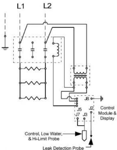
1(WT)

text_image
L1 L2 J8 J5 J7 J3 Control Module & Display Control, Low Water, & Hi-Limit Probe Leak Detection Probe1(NT)
text_image
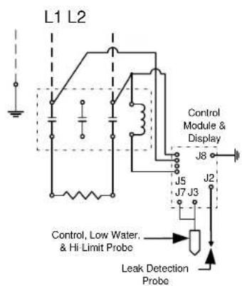
L1 L2 Control Module & Display J6 J5 J7 J3 J2 Control, Low Water, & Hi Limit Probe Leak Detection Probe10(WT)

text_image
L1 L3L2 J5 J7 J3 J8 J2 Control Module & Display Control, Low Water, & Hi-Limit Probe Leak Detection Probe10(NT)

text_image
L1 L3L2 Control Module & Display J8 J5 J2 J7 J3 Control, Low Water, & Hi-Limit Probe Leak Detection Probe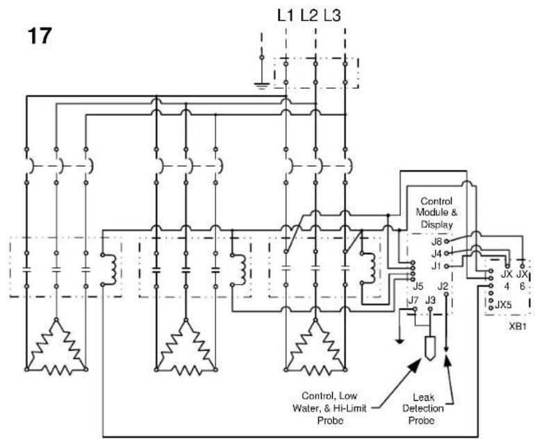
text_image
17 L1 L2 L3 Control Module & Display J8 J4 J1 J5 J2 J7 J3 JX JX 4 6 IX5 XB1 Control, Low Water, & Hi-Limit Probe Leak Detection Probe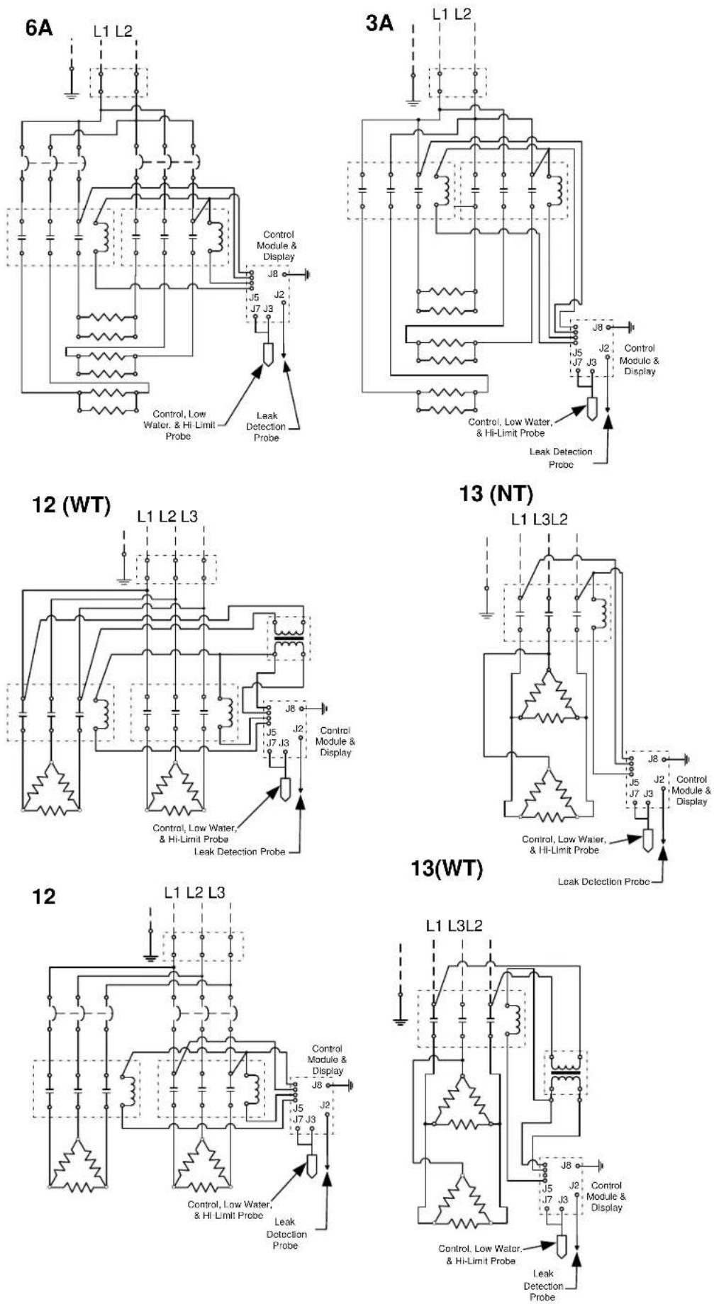
4(WT)
text_image
L1 L2 J5 J7 J3 J6 Control Module & Display Control, Low Water, & Hi-Limit Probe Leak Detection Probe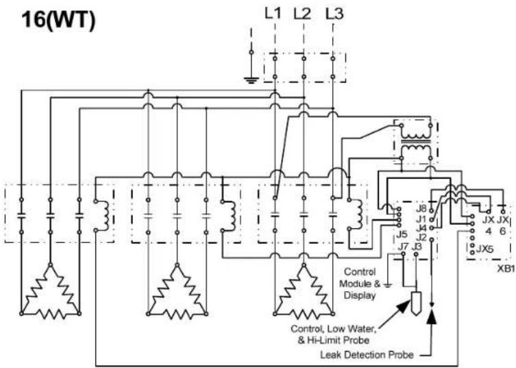
text_image
16(WT) L1 L2 L3 J8 J1 J4 J5 J7 J3 Control Module & Display Control, Low Water, & Hi-Limit Probe Leak Detection Probe JX JX 4 6 JX5 XB14
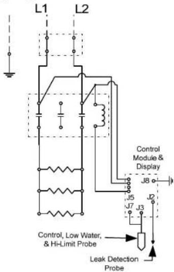
text_image
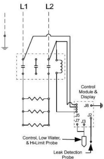
L1 L2 Control Module & Display J8 J5 J7 J3 Control, Low Water, & Hi-Limit Probe Leak Detection Probe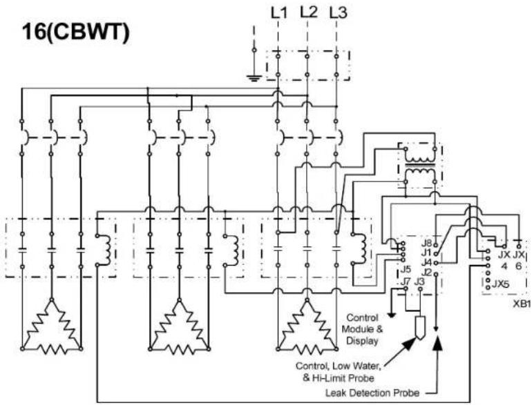
text_image
16(CBWT) L1 L2 L3 J8 J1 J4 J5 J7 J3 JX JX 4 6 JX5 XB1 Control Module & Display Control, Low Water, & Hi-Limit Probe Leak Detection Probe4 (DB)
text_image
L1 L2 Control Module & Display J8 J5 J2 J7 J3 Control, Low Water, & Hi-Limit Probe Leak Detection Probe
text_image
18 L1 L2 L3 J8 J5 J7 J3 J2 Control Module & Display Control, Low Water, & Hi-Limit Probe Leak Detection Probe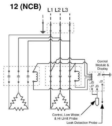
text_image
12 (NCB) L1 L2 L3 Control Module & Display J8 J5 J7 J3 J2 Control, Low Water, & Hi-Limit Probe Leak Delaction Probe
text_image
15 L1 L3L2 Control Module & Display J8 J5 J7 J3 J2 Control, Low Water, & Hi-Limit Probe Leak Detacation Probe
text_image
14 L1 L3L2 J8 J5 J7 J3 J2 Control, Low Water, & HI-Limit Probe Leak Detection ProbeTypical J6 Plumbing Connections
(Rear View)
flowchart
graph LR
    A["Inlet"] --> B["Gate Valve (Not Supplied)"]
    B --> C["Water Treatment System (optional)"]
    C --> D["Pressure Reducing Valve with Built-In Bypass"]
    D --> E["Temperature/Pressure Gauge"]
    E --> F["T&P Relief Valve"]
    F --> G["T&P Relief Valve Piping (Air Gap Must Conform To Code)"]
    G --> H["Drain Valve (Not Supplied)"]
    H --> I["3½" Dielectric Union (Optional)"]
    I --> J["3½" Dielectric Union (Optional)"]
    J --> K["T&P Relief Valve"]
    K --> L["Temperature/Pressure Gauge (Optional)"]
    L --> M["Shock Absorber (Optional)"]
    M --> N["Outlet"]
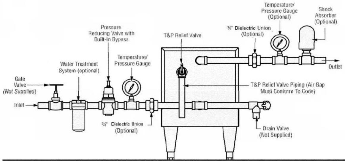
Typical J16 Plumbing Connections
(Front View)
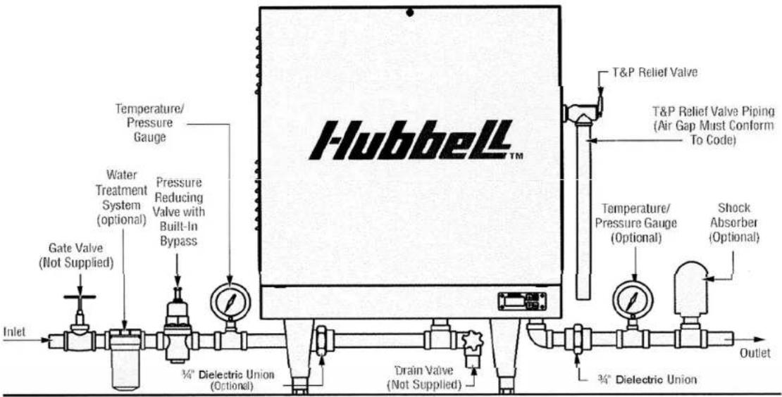
text_image
Hubbell™ T&P Relief Valve T&P Relief Valve Piping (Air Gap Must Conform To Code) Temperature/ Pressure Gauge Water Treatment System (optional) Pressure Reducing Valve with Built-In Bypass Gate Valve (Not Supplied) Inlet 3/4" Dielectric Union (Optional) Drain Valve (Not Supplied) 3/4" Dielectric Union Temperature/ Pressure Gauge (Optional) Shock Absorber (Optional) OutletTypical J3 Plumbing Connections (Front View, shown with optional legs)

text_image
Temperature/ Pressure Gauge (Optional) 3/4" Dielectric Union (Optional) T&P Relief Valve T&P Relief Valve Piping (Air Gap Must Conform To Code) Shock Absorber (Optional) Outlet Temperature/ Pressure Gauge (Optional) Temperature/ Pressure Gauge (Optional) Water Treatment System (optional) Pressure Reducing Valve with Built-In Bypass (Optional) Gate Valve (Not Supplied) Inlet 3/4" Dielectric Union (Optional) Drain Valve (Not Supplied)SECTION III – SCHEDULED MAINTENANCE AND OPERATION
WARNING / CAUTION
Before performing any maintenance procedure, make certain the power supply is turned OFF and cannot accidentally be turned on.
The water heater is automatic in its operation. It will maintain a full tank of water at the temperature setting of the controller. The water heater should not be turned on without first making sure that the tank is full of water and that all air has been released.
FREEZING
The tank should be fully drained in the event the electricity has been turned off and if there is danger of freezing.
NOTE: All controller variables come preset from the factory to include a preset temperature of 185^ F.
- To turn unit on or off:
a. Press the ON/OFF button on the display module.
b. Note that the controller will resume its last mode of operation if power is disconnected.
- To change setpoint temperature (the temperature is fully adjustable from 32^ to 194^ F ( 0^-90^ C):
a. Press the UP and DOWN arrows simultaneously to enter setpoint change mode.
b. Press the UP or DOWN button to change the setpoint temperature.
c. Pressing and holding the UP or DOWN button will scroll through the setpoint temperature.
d. To leave setpoint change mode
i. Wait 5 seconds without pushing any buttons or press the UP and DOWN buttons simultaneously.
- To view the number of operational hours (the number of hours when a contactor is pulled in) and software version:
a. Press the UP and DOWN arrows simultaneously to enter setpoint change mode.
b. Press the ON/OFF button.
c. Display will flash the software version (e.g. R14), HRS, followed by the hours in thousands of hours, followed by the hours.
i. Example: r 14, ll r S, 12 3, 4 5 6; indicates software version R1.4 and 123,456 hours.
d. To leave operational hours mode
i. Wait 5 seconds without pushing any buttons or press the UP and DOWN buttons simultaneously.
- Configuration Menu. (NOTE: Configuration menu change should only be made by qualified personnel).
a. With the controller turned OFF, to enter the configuration menu, press and hold the UP, DOWN, and ON/OFF buttons simultaneously for 5 seconds.
b. To scroll through menu settings, press the ON/OFF button.
c. To make a change to a menu setting use either the UP or DOWN arrow.
d. Settings:
i. Relays - sets the number of magnetic contactors used in the heater.
- r ##, where ## is the number of magnetic contactors (01 or 02). With XB1 installed ## can be 01 through 06.
ii. Low water detection - sets the low water detection on or off.
- L0n, for low water on. (Factory Default)
- LOF, for low water off.
iii. Low water reset – sets the low water reset for either automatic or manual
- LAU, for low water automatic reset. (Factory Default)
- LAn, for low water manual reset.
iv. Temperature units - sets the temperature units to either degrees Fahrenheit or Celsius.
- DEF, for degrees Fahrenheit. (Factory Default)
- DEC, for degrees Celsius.
v. Differential - sets the number of degrees below setpoint that the heater will resume heating after it has achieved setpoint.
- d##, where ## is the differential in degrees (1 to 20). (Factory set at 02)
vi. Display - sets the display to either setpoint or actual temperature.
- dSS, for display setpoint temperature. (Factory Default)
- dS t, for display actual temperature.
vii. Heater Interlock - sets the heater interlock mode to on or off. (Only available with r23 or later software).
- HoF, to disable the 24-volt interlock feature. (Factory Default)
- Hon, to enable the 24-volt interlock feature.
viii. XB1 Tem perature Setpoint - sets the setpoint for the operation of the XB1 relay operation.
e. To leave the configuration menu, wait 5 seconds without pushing any buttons or press the UP and DOWN buttons simultaneously.
- To reset any high-lim it, no probe, or low water (when in manual reset mode) fault condition, press the RESET button.
- Display
a. By default the display will show the setpoint of the booster heater.
b. The decimal points on the display, as shown below, indicate that the controller is calling for a contactor to pull in. If three or more contactors are installed, the third decimal point is used for all remaining contactors.
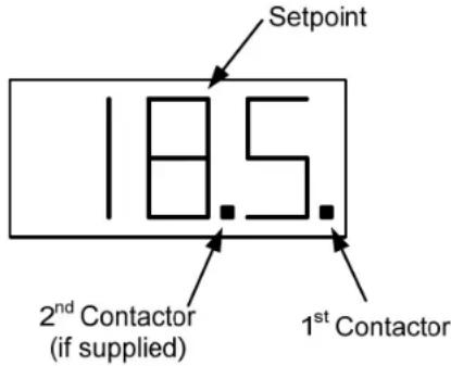
text_image
Setpoint 18.5 2nd Contactor (if supplied) 1st ContactorANNUAL INSPECTION
- Monitor water temperature
a. Let water heater com pletely heat to a designated temperature setting.
b. After controller satisfies (that is, when the magnetic contactor actually clicks off), draw water from as close as possible heater outlet and measure the temperature.
c. Compare the water temperature of outlet water to the temperature setting of the display when it satisfies. Normal variation between the two points is approximately ±5^ F.
d. If these two readings do not coincide within acceptable tolerances and verification has been made of the accuracy of the temperature-reading gauge, replace the control board and/or the sensor probe.
-
Lift test lever on relief valve and let water run through valve for a period of approximately 10 seconds. This will help flush away any sediment that might build up in water passageways.
-
Inspect element for leakage as follows:
a. Shut off power supply.
b. Remove front cover.
c. Visually inspect around heating element for evidence of leaks.
d. Rub around the heating element with a rag. Check for any evidence of moisture. If moisture is present or a water drip is observed, follow procedure outlined in Section V.
CAUTION: The area around the heating element may be hot.
- Scale and mineral build-up on heating elements is a normal condition. It is recommended that the heating element be removed for examination and if scaled, should be cleaned. In an area of known hard or poor water conditions, the elements may need to be checked more frequently. This will improve the efficiency of the heater and increase the element life.
NOTE: Failure of the elements due to scale and mineral build-up is not covered under warranty. See warranty for complete details.
a. Shut off power supply.
b. Drain the tank.
c. Remove front cover.
d. Disconnect the element wiring. It is recommended that one element at a time is removed to simplify re-wiring.
e. Unscrew element.
f. Lime scale removal
i. Place limed ends of the heating element in a de-limer solution, designed for potable water applications, and allow lime to dissolve. Do not allow de-limer to contact heating element terminals.
g. Other scale removal
i. Silicates, sulfates, and aluminates must be removed by scraping or other mechanical means. De-limers will not dissolve these types of scale.
h. Flush the cleaned ends of the elements with clean water.
i. Re-install element with new o-ring.
j. Re-attach element wires.
k. Continue until all heating elements are cleaned.
- Fill the heater following the filling instructions provided in Section II and check around the elements for leaks.
m. Re-apply power.
- Check for loose electrical connections. Tighten as necessary.
SECTION IV - TROUBLESHOOTING
ERROR MESSAGES
- Err, No, Prb
a. This message will flash when the controller does not detect that the probe is connected to the control board. To clear this error reinsert the probe connector and press RESET.
- Err, too, hot, ### (where ### is the actual temperature of the water.)
a. This message will display if the temperature of the water exceeds the high limit temperature setpoint. To clear this error, wait until the temperature is below the operating setpoint and press RESET. Note that the unit will not reset until the indicated temperature is below 195^ F. If this message continually occurs, follow the troubleshooting flow chart for continuous over-temperature condition.
- Err, No, H20
a. This message will display when the water level in the tank has dropped below the sensor probe. To clear this message, refill the tank. If the low water reset is set for automatic, the error will clear. If the low water reset is set for manual, when the tank is full press RESET. Check the heater and the piping for leaks. Check for mineral buildup on the probe and clean as required. Check for continuity between the yellow wire and ground. See diagram 2 on the following page.
- Err, H2O, LEA
a. This message displays if the leak detection sensor determines there is water in the base of the heater shell. To clear this message, remove the water from the leak detection sensor. Check the unit and piping for leaks.
- CC
a. This message displays if the display cable is installed into the control board backwards. To clear this message, remove and correctly install the display cable.
6.255
a. This message indicates that the probe is likely out of calibration. To clear this message, it is recommended that the probe be removed and replaced.
- HLD
a. This message indicates that the 24-volt interlock feature is enabled, there is no 24-volt signal present, and the heater is in standby mode. If it is not the intention to operate the heater with the 24-volt interlock feature, this feature should be disabled as shown in the controller operation section. (Only available with r23 or later software).
CONTACTOR CARE
- A chattering or humming from the contactor is due to dust or debris on the contact points that prevents the contactor from making proper contact. The debris can be removed by utilizing a can of antistatic cleaning and dusting spray (pressurized air) and spraying through the side of the contactor to remove the debris.
DISPLAY BUTTONS
- If the display randomly changes or does not respond when the buttons are pressed, loosen the four (4) screws holding the display to the base, reseat the display in the center of the opening, leaving the screws loose.
MISCELLANEOUS
- If the display flashes when the unit is first turned on or turned on after maintenance, check that the J5 terminal on the controller is engaging all four pins on the board.
- Note that before replacing the control board, display, or probe, it is recommended that the power supply to the booster heater be turned off at the main circuit breaker disconnect to the booster heater to reset and clear the electronic controller.
CAUTION: Do not use plumber's tape/Teflon tape/pipe dope when installing the probe. Tape will prevent the low water detection system from operating properly and will cause false low water errors. Lubricate O-ring prior to installation.
| Symptom | Probable | Cause Corrective Action |
| Water reaches setpoint temperature but does not last through the entire dishwasher cycle. | Low incoming water temperature. | Incoming water temperature must be adequate for the booster size. Increase the incoming water temperature. |
| Incoming water temperature is dropping. | Primary water supply is not adequate to continually provide correct temperature in sufficient quantities. Increase the supply of primary warm water. | |
| Water pressure is too high. | Higher water pressure uses an excessive supply of hot water. Verify a pressure reducing valve is installed and adjust the water pressure to 20 psi. | |
| Booster heater may be undersized. | The booster heater must be properly sized for the incoming water and rinse requirements of the dishwasher. If required, replace with a properly sized unit. | |
| Incorrect voltage. Voltage | available at the booster heater must be correct for unit. Verify voltage on all phases matches nameplate on the booster heater. | |
| If two magnetic contactors are utilized, one is not energizing. | Verify that both magnetic contactors are operating. If not, see the ‘Magnetic Contactor Troubleshooting’ section. | |
| One or more elements are not energizing. | Verify that each element is drawing the correct amperage. Replace elements as required. | |
| Water at the dishwasher is not the proper temperature. | Gauge(s) not reading correctly. | Check the temperature of the water with a thermometer to verify the gauges are working properly. Replace gauges, if required. |
| Temperature setpoint too low. | Adjust the temperature setpoint. | |
| Booster heater piping to the dishwasher is not insulated. | If there is more than 5 linear feet of piping between the booster heater and the dishwasher the piping should be wrapped in insulation or a recirculating system should be installed. | |
| Bypass valve is open or allowing water to pass when closed. | Verify that the bypass valve between the hot and warm water lines is closed. If condition continues, replace the bypass valve. |
| Symptom | Probable | Cause | Corrective Action |
| Temperature and pressure relief valve sccps | No pressure reducing valve or wrong valve installed causing excessive pressure in the unit. | The proper pressure reducing valve with high pressure bypass must be installed in the inlet water line to allow for the expansion of water. | |
| Pressure reducing valve bypass is blocked. | Clean the bypass or install a new valve with a built-in bypass. | ||
| Anti-siphon valve or check valve installed in the warm water inlet line. | Remove the anti-siphon valve or the check valve to allow for the expansion of the water or install a back pressure relief valve. | ||
| Temperature and pressure relief valve opens and/or high limit temperature error occurs. | Unit is overheating due to improper P65 probe calibration. | See the ‘P65 Probe Troubleshooting’ section. | |
| Unit is overheating due to the magnetic contactor staying in the closed position. | See the ‘Magnetic Contactor Troubleshooting’ section. | ||
| Booster heater does not heat at all. | Main supply circuit breaker tripped. | Check and/or reset the circuit breaker. | |
| Booster heater circuit breaker tripped. | If unit is supplied with a circuit breaker, check and/or reset the circuit breaker. | ||
| Booster in high limit. If a high limit error occurs, allow water to cool and press the reset button. If error continues see symptom “Temperature and pressure relief valve opens and/or high limit temperature error occurs”. | |||
| Low water error. Verify that booster heater is full of water. If error is still present see the ‘P65 Probe Troubleshooting’ section. | |||
| Magnetic contactor does not energize. | See the ‘Magnetic Contactor Troubleshooting’ section. | ||
| No power to control board (T1000) or display (TD1000) not lit. | Reseat the display (TD1000) ribbon cable in the control board (T1000) connector. If the display is still not lit, see the ‘Control Board (T1000) / Display (TD1000) Troubleshooting’ section. | ||
| Element Failure Disconnect the wires from each element and verify that the resistance (ohms) value for each element is correct. Replace elements as required. | |||
| Incorrect Configuration Settings | Verify and correct configuration settings as required. | ||
CONTROL BOARD (T1000) / DISPLAY (TD1000) TROUBLESHOOTING
-
Verify proper power supply voltage between each phase (L1 to L2, L2 to L3, and L1 to L3). The power supply voltage should match the voltage listed on the booster nameplate. If voltage is incorrect, check main supply wiring or replace unit with proper booster heater.
-
Check for 208/240VAC between pin 1 (white wire) and pin 2 (black wire) of the J5 connector on the T1000 control board. If no voltage is present, skip to step 4.
-
If 240VAC is present, check for 24VDC between D1 and ground. If 24VDC is present replace the display (TD1000). If 24VDC is not present replace the control board (T1000).

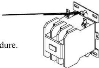
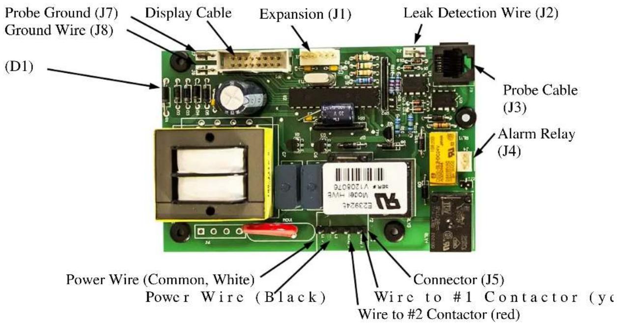
text_image
Probe Ground (J7) Ground Wire (J8) (D1) Display Cable Expansion (J1) Leak Detection Wire (J2) Probe Cable (J3) Alarm Relay (J4) Power Wire (Common, White) Power Wire (Black) Connector (J5) Wire to #1 Contactor (yellow) Wire to #2 Contactor (red)-
If a transformer is installed, verify proper power supply voltage to the primary side of the transformer and verify approximately 240VAC on the secondary side of the transformer. If voltage is present of the primary side but not on the secondary side, replace the transformer.
-
If circuit breakers are installed, verify that the circuit breaker is ON. Verify proper power supply voltage between each phase (L1 to L2, L2 to L3, and L1 to L3) to the line side of each circuit breaker and to the load side of each circuit breaker. If voltage is present of the line side but not on the load side, replace the circuit breaker.
-
Verify that the booster heater is wired according to the proper wiring schematic for the unit. Correct as required. If unit still does not operate, contact the factory.
MAGNETIC CONTACTOR TROUBLESHOOTING
-
With the unit ON and calling for heat, check for lit decimal points on the display. If the unit has a single contactor, the first decimal to the right of the display should be lit. If two decimals are lit, verify that the configuration is set for one contactor. If the unit has two contactors, verify that two decimals are lit. If only one decimal is lit, verify that the configuration is set for two contactors. If no decimals are lit, continue to the 'P65 Probe Troubleshooting' section.
-
With the unit ON and calling for heat and one decimal lit, check for 240VAC between pin 1 (white wire) and pin 4 (yellow wire) of the J5 connector on the T1000 control board. If no voltage is present, replace the control board (T1000). If voltage is present, check for voltage across the contactor coil. If voltage is present at the contactor coil, replace the magnetic contactor. If no voltage is present, verify that the booster heater is wired according to the proper wiring schematic for the unit.
-
If the unit has two contactors, with the unit ON and calling for heat and two decimals lit, check for 240VAC between pin 1 (white wire) and pin 3 (red wire) of the J5 connector on the T1000 control board. If no voltage is present, replace the control board (T1000). If voltage is present, check for voltage across the contactor coil. If voltage is present at the contactor coil, replace the magnetic contactor. If no voltage is present, verify that the booster heater is wired according to the proper wiring schematic for the unit.
P65 PROBE TROUBLESHOOTING
- Unplug and reseat the P65 probe wire in the jack on the T1000 control board. Note that the error message “Err, No, Prb” will be displayed and the reset button must be pressed to clear the message.
- If problem persists, unplug the P65 probe from the control board and plug into the RJ45 pigtail (not supplied).
- If the problem is with temperature control or high limit:
a. Change the configuration to 'dS t' to display the actual water temperature.
b. Check the temperature of the water with a thermometer and compare that with the temperature on the display. If the two temperatures coincide, replace the T1000 control board. If the two temperatures do not coincide, continue to the next step.
c. Unplug the P65 probe from the control board and plug into the RJ45 pigtail (not supplied). Check the resistance value (ohms) between the blue wire of the pigtail (#1) and the red wire of the pigtail (#4). Compare the resistance value measure with the chart below at the measured temperature of the water. If the two values coincide, replace the T1000 control board. If the two values do not coincide, replace the P65 sensor
- If the problem is with low water:
a. Verify that the unit is filled with water.
b. Check for continuity between the yellow wire of the pigtail (#2) and ground. If continuity exists, replace the T1000 control board. If no continuity exists, replace the P65 sensor probe.

text_image
Blue Yellow Green Red Black White Probe End RJ45 Pigtail 1 2 3 4 5 6 To verify that there is water in the tank check for continuity between yellow(#2) and ground.| Thermistor Resistance vs. Temperature | |
| Water Temperature Resistance (±3%) | |
| 70°F | 11883Ω |
| 80°F | 9299Ω |
| 90°F | 7334Ω |
| 100°F | 5828Ω |
| 110°F | 4664Ω |
| 120°F | 3758Ω |
| 130°F | 3048Ω |
| 140°F | 2488Ω |
| 150°F | 2043Ω |
| 160°F | 1687Ω |
| 170°F | 1400Ω |
| 180°F | 1169Ω |
| 190°F | 980Ω |
SECTION V - SERVICING AND REPLACEMENT OF PARTS
WARNING / CAUTION
Before servicing or replacing any part, make sure to turn the power supply to the unit OFF.
HEATING ELEMENT
- Disconnect power from unit.
- Shut off incoming water supply.
- Attach hose to drain connection.
- Lift m anual release lever on relief valve to let air into system or break union on outgoing water line.
- Drain water from tank.
- Disconnect the wires from the heating element terminals.
- Unscrew element with a 1-7/8" 6-point socket with no bevel.

natural_image
Mechanical assembly diagram showing a shaft and housing with directional arrows indicating motion (no text or labels)O-Ring Groove O-Ring
natural_image
Technical line drawing of a mechanical component with two arrows pointing to features (no text or symbols)Terminal Connections
220 Buna-N O-Ring
- Install new #220 Buna-N o-ring gasket and install new heating element. NOTE: Hubbell recommends lubricating the o-ring with Parker O-Lube prior to installation.
- Rewire element according to the wiring diagram as shown in the Section II.
- Fill tank and check around element for any leaks.
MAGNETIC CONTACTOR
- Disconnect power from unit.
- Disconnect line and load wires to contactor.
- Disconnect the control circuit wires.
Control Wires
Line Wires
Load Wires
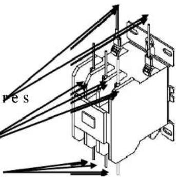
text_image
resMounting Screws
natural_image
Technical line drawing of an electrical contactor component (no text or symbols)- Loosen holding screws and remove contactor.
- Replace with new contactor using reverse procedure.
CONTROL BOARD
- Disconnect power from unit.
- Disconnect display cable, probe cable (J3) and probe ground (J7), leak detection wire (J2), ground wire (J8), and terminal block (J5) from the control board. NOTE: The terminal block (J5) is removable by grasping the terminal block on the ends and
pulling straight away from the board.
text_image
Probe Ground (J7) Ground Wire (J8) (D1) Display Cable Expansion (J1) Leak Detection Wire (J2) Probe Cable (J3) Alarm Relay (J4) Power Wire (Common, White) Power Wire (Black) Connector (J5) Wire to #1 Contactor (ye) Wire to #2 Contactor (red)Note: Probe connector J3 comes filles with a dielectric gel that should remain in the connector.
-
Rem ove four (4) screws securing control board to panel.
-
Remove and replace control board.
-
Reconnect wires disconnected in step 2. NOTE: When reconnecting the ribbon cable, be sure to have the key on the cable align with the slot in the connector.
-
Connect power to unit.
RELIEF VALVE
- Disconnect power from unit.
- Shut off incoming water supply.
- Attach hose to drain connection.
- Lift m anual release lever on relief valve to let air into system or break union on outgoing water line.
- Drain water from tank.
- Disconnect overflow piping.
- Unscrew relief valve, remove assembly and replace with new one.
- Connect overflow piping.
- Turn on incoming water supply and check for leaks.
- Connect power to unit.
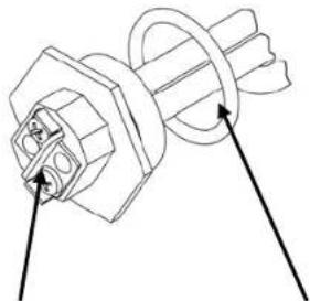
P65 SENSOR PROBE
- Disconnect power from the unit.
- Unplug the P65 probe connector from J3 and the probe ground from J7 on the T1000 control board. Probe Ground (J7)

natural_image
Close-up of an electronic circuit board with visible components and wiring (no readable text or symbols)
text_image
Probe Ground (J7) Probe Connection (J3)-
Twist the cord and shrink-wrap end of the P65 probe (or cut the shrink-wrap with a sharp knife) to loosen the P65 sensor assembly from the P65 thermowell.
-
Remove the old P65 sensor assembly by pulling on the cord coming out of the P65 thermowell.
Note: It is unnecessary to unscrew the thermowell from the vessel to replace the P65 sensor.
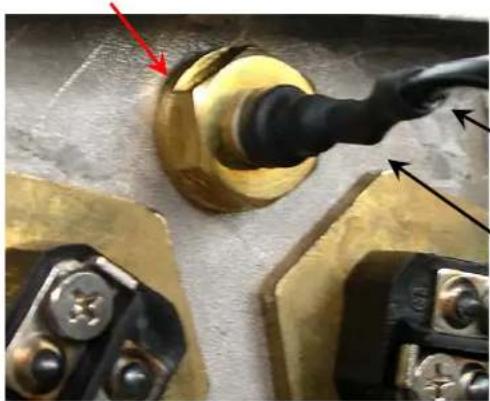
natural_image
Close-up of a mechanical component with a gold-colored knob and black cable, showing no visible text or symbols.Cord

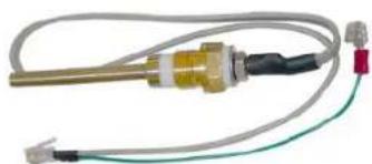
text_image
P65 SensorShrink-Wrap Cap
- Insert the new P65 sensor assembly into the P65 thermowell. Be sure to insert the sensor until the shrink-wrap cap engages the threads on the end of the thermowell.
Note: The new sensor and cord assembly is push-fit onto the end of the thermowell threads. Do not twist the new sensor and cord assembly into the thermowell. The thermal conductive heat transfer paste inside the thermowell is sufficient for replacement sensors. Adding additional paste is not required.
-
Plug P65 probe connector into the T1000 control board.
-
Turn on power to the unit. If display shows "Err, No, Prb", press the reset button.
P65 THERMOWELL
-
Follow steps 1-4 for removing the P65 Sensor Probe above.
-
Shut off incoming water supply.
-
Attach hose to drain connection.
-
Lift manual release lever on relief valve to let air into system or break union on outgoing water line.
-
Drain water from tank.
-
Remove the thermowell from tank using a 13/16" socket.
-
Install new #115 Buna-N o-ring gasket and install new thermowell. NOTE: Hubbell recommends lubricating the o-ring with Parker O-Lube prior to installation. WARNING: Do not remove the jam nut.

natural_image
Close-up of a mechanical component with a black pipe fitting and a yellow base, no visible text or symbolsThermowell
-
Reinstall or install a replacement P65 sensor probe in accordance with steps 5 and 6 above.
-
Refill tank.
-
Check for leaks. Retighten as required.
-
Turn on power to the unit.
-
Note that to resume operation the controller will need to be reset by pressing the 'RESET' button on the display.
natural_image
Close-up of a metallic heating element with coiled wires and terminal connectors (no text or symbols visible)CAUTION: Do not use plumber's tape/Teflon tape/pipe dope when installing the P65 Thermowell. Tape will prevent the low water detection system from operating properly and will cause false low water errors. Lubricate O-ring prior to installation. Tighten probe at the brass hex flats only.
SECTION VI - SERVICE PARTS LIST
| Category Description Volts Ohms Hubbell P/N | ||||
| Accessories Bronze Pressure Reducing Valve N45BU | ||||
| Plastic Legs (Price each, 4 Req'd.) 61649NOBN5T4 | ||||
| Nickel Plated Legs (Price each, 4 Req'd.) AE61-4002-C | ||||
| Stainless steel adjustable legs (Price each) A50-5048-C | ||||
| Floor Mount Legs S/S (Price cach, 4 Req'd.) A50-9939-C | ||||
| Temp. and Pressure Gauge | ||||
| Diclectirc Union, 3/4" DIELECTRIC UNION | ||||
| Relief Valve (up to 58 kw) 100XL .75 150LB | ||||
| Relief Valve (64-90 kw) 40XL-4 1 150LB | ||||
| Slide Brackets (J6 models only, 2 per set) J6 SLIDE BRACKET | ||||
| J6, 3 Element Plastic Protective Shroud (1 to 18 kW) | ||||
| J6, 6 Element Plastic Protective Shroud (24 to 58.5 kW) | ||||
| J16 Element Plastic Protective Shroud | ||||
| Water Treatment System (blended phosphate) | ||||
| Replacement cartridge for water treatment | ||||
| Circuit Breakers | 60 amp | CB 60 AMP | ||
| 70 amp | CB 70 AMP | |||
| 80 amp | CB 80 AMP | |||
| 90 amp | CB 90 AMP | |||
| 100 amp | CB 100 AMP | |||
| Contactors | 20 Amp Resistive, 15 Amp Inductive, 208/240 VAC Coil | C25DNF315B | ||
| 40 Amp Resistive, 30 Amp Inductive, 208/240 VAC Coil | C25DNF330B | |||
| 50 Amp Resistive, 40 Amp Inductive, 208/240 VAC Coil | C25DNF340B | |||
| 65 Amp Resistive, 50 Amp Inductive, 208/240 VAC Coil | C25DNF350B | |||
| 75 Amp Resistive, 60 Amp Inductive, 208/240 VAC Coil | C25FNF360B | |||
| 90 Amp Resistive, 75 Amp Inductive, 208/240 VAC Coil | C25FNF375B | |||
| Elements J4, J6, and J16 (Note: Each element is supplied with an O-Ring) | 2000 Watts | 208 | 21.6 | C1315-2 |
| 4000 Watts | 208 | 10.8 | C1315-3 | |
| 5000 Watts | 208 | 8.7 | C1315-4 | |
| 6000 Watts | 208 | 7.2 | C1315-5 | |
| 6500 Watts | 208 | 6.7 | C2315-6 | |
| 7150 Watts | 208 | 6.1 | C2315-7 | |
| 9000 Watts | 208 | 4.8 | N2375-9 | |
| 9600 Watts | 208 | 4.5 | N2375-10 | |
| 2000 Watts | 240 | 28.8 | C1315-11 | |
| 3000 Watts | 240 | 19.2 | C1315-12 | |
| 3500 Watts | 240 | 16.5 | C1315-13 | |
| 4000 Watts | 240 | 14.4 | C1315-14 | |
| 4500 Watts | 240 | 12.8 | C1315-15 | |
| 5000 Watts | 240 | 11.5 | C1315-16 | |
| 6000 Watts | 240 | 9.6 | C1315-17 | |
| 6500 Watts | 240 | 8.9 | C1315-18 | |
| 6750 Watts | 240 | 8.5 | C1315-34 | |
| 7500 Watts | 240 | 7.7 | C2315-19 | |
| 9000 Watts | 240 | 6.4 | N2375-20 | |
| 9750 Watts | 240 | 5.9 | N2375-21 | |
| 2000 Watts | 480 | 115.2 | C1315-22 | |
| 2333 Watts | 480 | 98.8 | C1315-23 | |
| 3000 Watts | 480 | 76.8 | C1315-24 | |
| 3500 Watts | 480 | 65.8 | C1315-25 | |
| 4000 Watts | 480 | 57.6 | C1315-26 | |
| 4500 Watts | 480 | 51.2 | C1315-27 | |
| 5000 Watts | 480 | 46.1 | C1315-28 | |
| 6000 Watts | 480 | 38.4 | C1315-29 | |
| 6500 Watts | 480 | 35.4 | C1315-30 | |
| 7500 Watts | 480 | 30.7 | C1315-31 | |
| 9000 Watts | 480 | 25.6 | N2375-32 | |
| 9750 Watts | 480 | 23.6 | N2375-33 | |
| 6750 Watts | 480 | 34.1 | C1315-35 | |
| Extra O Ring (#220 Buna-N) | O RING J MODEL | |||
| Elements J3 (Note: Each element is supplied with an O-Ring) | 1900 Watts | 120 | 7.6 | C1315-39 |
| 3300 Watts | 208 | 13.1 | C1315-40 | |
| 3460 Watts | 208 | 17.6 | C1315-36 | |
| 3800 Watts | 240 | 15.2 | C1315-37 | |
| 3800 Watts | 277 | 20.2 | C1315-38 | |
| 3800 Watts | 346 | 31.5 | C1315-41 | |
| Category Description | Volts Ohms Hubbell P/N | |||
| Misc. Electrical | Control Board T1000 | |||
| Digital Display Module (with overlay and J16 Extension) TD | 000 | |||
| J16 Ribbon Cable Extension RIBBON CABLE J16 | ||||
| Display Overlay OVERLAY J MODEL | ||||
| Probe Sensor P65 | ||||
| Probe Thermowell (includes #115 Buna-N O-Ring) P65 WELL | ||||
| Transformer 480-208V, 50VA B050-3299-3 | ||||
| Transformer 600-195V, 50VA B050-3350-3 | ||||
| Transformer 380-185V, 50VA B050-3351-3 | ||||
| Transformer 480-240V, 100VA B100PU1519JJ | ||||
| Transformer 600-195V, 100VA B100-3350-3 | ||||
| Transformer 380-220V, 100VA B100RFD34XJ | ||||
| Transformer 480-208V (J3 and J4 only) TRAN 480-208 25VA | ||||
| Transformer 380-208V (J3 only) TRAN 380-208 25VA | ||||
| Transformer 277-208V (J3 only) TRAN 277-208 25VA | ||||
| Transformer 600-208V (J3 only) TRAN 600-208 25VA | ||||
| Power Distribution Block 175 amp 2 pole | 16220-2 | |||
| Power Distribution Block 175 amp 3 pole | 16220-3 | |||
| Power Distribution Block 310 amp 3 pole | 16023-3 | |||
| Diffuser Assembly with Nipple | J6 DIFFUSER | |||
| RJ45 Pigtail for P65 Probe Testing | P65-RJ45 TESTER | |||
| Low Temperature Interlock | XB1 | |||
| 24-Volt Interlock Adapter | PLUG ADAPTER J1 | |||
| Remote Alarm Plug Adapter PLUG ADAPTER J4 | ||||
| Wire #18 200C (black,white,red,yellow) Tefzel 750 | WIRE #18 200C "COLOR" | |||
| Wire #12 200C (blue or red) Tefzel 750 WIRE #12 200C "COLOR" | ||||
| Wire #10 200C (blue or red) Tefzel 750 WIRE #10 200C "COLOR" | ||||
| Wire #8 200C (blue or red) Tefzel 750 | WIRE #8 200C "COLOR" | |||
| Wire #6 200C (black) Tefzel 750 | WIRE #6 200C BLACK | |||
| Vessel(includes insulationand o-rings) | J6 Vessel with 3 Element Openings | J6-3 TANK | ||
| J6 Vessel with 6 Element Openings | J6-6 TANK | |||
| J16 Vessel with 3 Element Openings | J16-3 TANK | |||
| J16 Vessel with 6 Element Openings | J16-6 TANK | |||
| J16 Vessel with 9 Element Openings | J16-9 TANK | |||
| J3 Vessel | J3 TANK | |||
| J4 Vessel | J411R TANK | |||
| Stainless SteelEnclosure Parts | J6, 3 Element Base | J6-3 BASE | ||
| J6, 3 Element Top Enclosure | J6-3 JACKET | |||
| J6, 3 Element Front Cover | J6-3 FRONT COVER | |||
| J6, 6 Element Base | J6-6 BASE | |||
| J6, 6 Element Top Enclosure | J6-6 JACKET | |||
| J6, 6 Element Front Cover | J6-6 FRONT COVER | |||
| J16 Base | J16 BASE | |||
| J16 Top Enclosure | J16 JACKET | |||
| J16 Front Cover | J16 FRONT COVER | |||
| J3 Base | J3 BASE | |||
| J3 Top Enclosure | J3 JACKET | |||
| J3 Front Cover | J3 FRONT COVER | |||
| J4 Base | J4 BASE | |||
| J4 Top Enclosure | J4 JACKET | |||
| J4 Front Cover | J4 FRONT COVER | |||
SECTION VII - TORQUE VALUES
| Part | P/N | Wire | Torque Size (in·lbs) | Torque (ft·lbs) | |
| Element to Tank | All | N/A | 600 | 50 | |
| Wire to Element | All | All | 15 | 1.25 | |
| Probe to Tank All N/A 300 25 | |||||
| Wire to Ground Lug | KA8C | All | 25 | ||
| KA4C | All | 45 | |||
| Wire to Circuit Breaker | All | #14-#10 | 35 | ||
| #8 | 40 | 3.33 | |||
| #6-#4 | 45 | 3.75 | |||
| Transformer | All | All | 15 | 1.25 | |
| Wire to Control Board | All | All | 3.5 | 0.29 | |
| Wire to Contactor | C25DNF315B | #14-#12 | 15 | ||
| C25DNF330B | #10 | 25 | 2.08 | ||
| C25DNF340B | #8 | 40 | 3.33 | ||
| C25DNF350B | #6-#4 | 45 | 3.75 | ||
| C25FNF360B | #14-#10 | 40 | |||
| C25FNF375B | #8 | 45 | 3.75 | ||
| #6-#4 | 50 | 4.17 | |||
| Wire to Power Distribution Block | 16023-3 | Line | All | 275 | 22.92 |
| 16023-2 | Load | #14-#10 | 20 | 1.67 | |
| #8 | 25 | 2.08 | |||
| #6-#4 | 35 | 2.92 | |||
| 63133 | Line | #14-#8 | 50 | 4.17 | |
| 63132 | #6-2/0 | 120 | 10 | ||
| Load | #14-#10 | 20 | 1.67 | ||
| #8 | 25 | 2.08 | |||
| #6-#4 | 35 | 2.92 | |||
| Control Board to Panel | All | N/A | 10 | 0.83 | |
| Display to Base | All N/A | 10 | 0.83 | ||
| All Other Components to Panel | All | N/A | 20 | 1.67 | |
2.08 3.75 2.92
1.25 3.33
SECTION VIII – WARRANTY INFORMATION
LIMITED WARRANTY
- PRODUCT WARRANTY. Hubbell warrants the booster heater it manufactures and its components (the "Product") to be free from defects in materials and workmanship, under normal use and service for the period of time identified below beginning from the date of installation, provided that the product is installed within three (3) months of date of shipment from Hubbell and when the Product is installed and maintained in accordance with Hubbell's written instructions (see operators manual for details). Owner must establish the Product's purchase date by means satisfactory to Hubbell in its sole discretion.
TANK and COMPONENTS: One (1) year parts and labor
TANK ONLY: Ten (10) years Non Pro-Rated
REPLACEMENT PARTS: Thirty (30) days parts only, no labor, from date of purchase
SUCH WARRANTIES DO NOT COVER:
- Product failure (including but not limited to the tank and/or heating elements) caused by liming, sediment buildup, chemical corrosion, chlorine corrosion, or freezing.
- Temperature or other controller setting adjustments, pressure reducing valve adjustments, resets, and plumbing leaks.
- Product misuse, tampering or misapplication, accidental damage, improper installation or the application of improper voltage.
• Costs incurred for shipping, delivery, handling, and/or administrative charges. - For the tank warranty after the first year, all labor, shipping, installation costs, and components (other than the tank) are the responsibility of the owner.
- With respect to labor warranty within the first year, overtime, holiday, weekend or any other non-standard labor rate.
- Excessive and unreasonable labor rates and/or travel expenses as determined by Hubbell in its sole discretion.
THE FOREGOING WARRANTIES ARE EXCLUSIVE AND IN LIEU OF ANY OTHER WARRANTY, EXPRESSED OR IMPLIED, INCLUDING BUT NOT LIMITED TO ANY IMPLIED WARRANTY OR MERCHANTABILITY OR FITNESS FOR A PARTICULAR PURPOSE OR PATENT OR OTHER INTELLECTUAL PROPERTY RIGHT INFRINGEMENT.
- LIMITATION OF REMEDIES AND DAMAGES. Hubbell's liability and Buyer's exclusive remedy hereunder will be limited solely, at Hubbell's option, to repair or replacement by a Hubbell authorized service agency (other than where Buyer is located outside of the United States or Canada, in which case Hubbell's liability and Buyer's exclusive remedy hereunder will be limited solely to replacement of part under warranty) with respect to any claim made within the applicable warranty period referred to above. Without limiting the generality of the foregoing, all warranty items shall be returned by Buyer, at its sole expense, to the Hubbell factory (45 Seymour Street Stratford, CT 06615) for replacement or repair. Hubbell reserves the right to accept or reject any such claim in whole or in part. Hubbell will not accept the return of any product without prior written approval from Hubbell, and all such approved returns shall be made at Buyer's sole expense. HUBBELL WILL NOT BE LIABLE, UNDER ANY CIRCUMSTANCES, FOR CONSEQUENTIAL OR INCIDENTAL DAMAGES, INCLUDING BUT NOT LIMITED TO LABOR COSTS OR LOST PROFITS RESULTING FROM THE USE OR INABILITY TO USE THE PRODUCTS OR FROM THE USE OF OR INABILITY TO USE THE PRODUCTS OR FROM THE PRODUCTS BEING INCORPORATED IN OR BECOMING A COMPONENT OF ANY OTHER PRODUCT OR GOODS.
NOTES