
CSSMP15X10 - Unknown Chief - Free user manual and instructions
Find the device manual for free CSSMP15X10 Chief in PDF.

| Product Type | Sliding Storage Panel (Accessory) |
| Model Number | CSSMP15X10 |
| Brand | Chief (a brand of Legrand) |
| Weight Capacity | 15 lbs (6.8 kg) |
| Dimensions (Approx.) | 15 x 10 inches (381 x 254 mm) |
| Mounting Options | Wall mount or Extrusion mount |
| Material | Steel with powder coat finish |
| Included Hardware | Drywall anchors (4), #10 x 1" screws (4), 5/16-18 x 3/8" screws (4), slot nuts (2), washers (20), plastic rivet (1) |
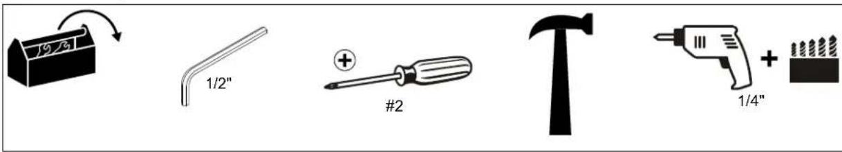
| Required Tools | Phillips screwdriver, drill, pencil, open-ended wrench, hex-head wrench |
| Installation Method | Directly to wall or onto Chief extrusion track |
| Orientation | Horizontal only; clip must be at bottom |
| Component Attachment | Removable mounting plate with keyhole slots; secured with clip and optional plastic rivet |
| Intended Use | Indoor use only; accessory for AV mounting systems |
| Compatibility | Chief extrusion systems and wall surfaces |
| Safety Certifications | Complies with Legrand | AV safety standards |
| Warranty | Refer to Legrand | AV warranty policy |
| Cleaning Instructions | Wipe with a dry cloth; avoid harsh chemicals |
| Repairability | No user-serviceable parts; contact Legrand | AV for support |
Frequently Asked Questions - CSSMP15X10 Chief
User questions about CSSMP15X10 Chief
0 question about this device. Answer the ones you know or ask your own.
Ask a new question about this device
Download the instructions for your Unknown in PDF format for free! Find your manual CSSMP15X10 - Chief and take your electronic device back in hand. On this page are published all the documents necessary for the use of your device. CSSMP15X10 by Chief.
USER MANUAL CSSMP15X10 Chief
INSTALLATION INSTRUCTIONS

natural_image
Technical line drawing of a mechanical assembly with two parallel plates and internal compartments (no text or symbols)Sliding Storage Panel
DISCLAIMER
Legrand | AV and its affiliated corporations and subsidiaries (collectively “Legrand | AV”), intend to make this manual accurate and complete. However, Legrand | AV makes no claim that the information contained herein covers all details, conditions or variations, nor does it provide for every possible contingency in connection with the installation or use of this product. The information contained in this document is subject to change without notice or obligation of any kind. Legrand | AV makes no representation of warranty, expressed or implied, regarding the information contained herein. Legrand | AV assumes no responsibility for accuracy, completeness or sufficiency of the information contained in this document.
DEFINITIONS
MOUNTING SYSTEM: A MOUNTING SYSTEM is the primary Chief product to which an accessory and/or component is attached.
ACCESSORY: AN ACCESSORY is the secondary Chief product which is attached to a primary Chief product, and may have a component attached or setting on it.
COMPONENT: A COMPONENT is an audiovisual item designed to be attached or resting on an accessory or mounting system such as a video camera, CPU, screen, display, projector, etc.

WARNING: A WARNING alerts you to the possibility of serious injury or death if you do not follow the instructions.

CAUTION: A CAUTION alerts you to the possibility of damage or destruction of equipment if you do not follow the corresponding instructions.

IMPORTANT SAFETY INSTRUCTIONS

WARNING: Failure to read, thoroughly understand, and follow all instructions can result in serious personal injury, damage to equipment, or voiding of factory warranty! It is the installer's responsibility to make sure all accessories are properly assembled and installed using the instructions provided.

WARNING: Exceeding the weight capacity can result in serious personal injury or damage to equipment! It is the installer's responsibility to make sure the combined weight of all components attached to accessory does not exceed 15 lbs (6.8 kg).

WARNING: Use this accessory only for its intended use as described in these instructions. Do not use attachments not recommended by the manufacturer.

WARNING: Never operate this accessory if it is damaged. Return the accessory to a service center for examination and repair.

WARNING: Do not use this accessory outdoors.
--SAVE THESE INSTRUCTIONS--
DIMENSIONS
![1.43 [36.3] 22.71 [576.7] 16.68 [423.6] 21.00 [533.3] 20.39 [517.8] 10.00 [254.0] 21.30 [541.0] 22.00 [558.8] FRONT VIEW SLIDE OPEN FRONT VIEW SLIDE CLOSED 4X 0.26 [6.5] 7.00 [177.8] WALL MOUNTING HOLES 7.70 [195.6] MOUNTING TO EXTRUSION 1.29 [32.8] R0.38 [9.5] R0.17 [4.3] 1.09 [27.6] REMOVABLE LEVER LOCK PLATE/COMPONENT MOUNTING SURFACE BACK VIEW SLIDE CLOSED 0.50 [12.7] 9.85 [250.1] 15.86 [402.8] 17.11 [434.7] SIDE VIEW LEVER LOCK FRONT VIEW LEVER LOCK DIMENSIONS: INCHES [MILLIMETERS]](/content/2026/06/1218863/images/c4f0b2afb3bf83fedc684ae0b7e6b48f7fa3a88cefe0076e13758bc556826c4c.jpg)
LEGEND
 | Tighten Fastener |  | Pencil Mark |
| Apretar elemento de fijación | Marcar con lápiz | ||
| Befestigungsteil festziehen | Stiftmarkierung | ||
| Apertar fixador | Marcar com lápis | ||
| Serrare il fissaggio | Segno a matita | ||
| Bevestiging vastdraaien | Potloodmerkteken | ||
| Serrez les fixations | Marquage au crayon | ||
 | Loosen Fastener |  | Drill Hole |
| Aflojar elemento de fijación | Perforar | ||
| Befestigungsteil lösen | Bohrloch | ||
| Desapertar fixador | Fazer furo | ||
| Allentare il fissaggio | Praticare un foro | ||
| Bevestiging losdraaien | Gat boren | ||
| Desserrez les fixations | Percez un trou | ||
 | Phillips Screwdriver |  | Adjust |
| Destornillador Phillips | Ajustar | ||
| Kreuzschlitzschraubendreher | Einstellen | ||
| Chave de fendas Phillips | Ajustar | ||
| Cacciavite a stella | Regolare | ||
| Kruiskopschroevendraaier | Afstellen | ||
| Tournevis à pointe cruciforme | Ajuster | ||
 | Open-Ended Wrench |  | Remove |
| Llave de boca | Quitar | ||
| Gabelschlüssel | Entfernen | ||
| Chave de bocas | Remover | ||
| Chiave a punte aperte | Rimuovere | ||
| Steeksleutel | Verwijderen | ||
| Clé à fourche | Retirez | ||
 | By Hand |  | Optional |
| A mano | Opcional | ||
| Von Hand | Optional | ||
| Com a mão | Opcional | ||
| A mano | Opzionale | ||
| Met de hand | Optie | ||
| À la main | En option | ||
 | Hex-Head Wrench |  | Security Wrench |
| Llave de cabeza hexagonal | Llave de seguridad | ||
| Sechskantschlüssel | Sicherheitsschlüssel | ||
| Chave de cabeça sextavada | Chave de segurança | ||
| Chiave esagonale | Chiave di sicurezza | ||
| Zeskantsleutel | Veiligheidssleutel | ||
| Clé à tête hexagonale | Clé de sécurité |
TOOLS REQUIRED FOR INSTALLATION
PARTS

Installation Hardware Kit

A (4)
[10-12 x 1"
drywall anchor]

D (4)
5/16-18 x 3/8"
B (4)
10 x 1"
E (20)
.625x.140x.031


![G (1) [CSSMP15X10 Storage Panel]](/content/2026/06/1218863/images/59921a8238e2ab6e7dce135952fe504e9b5a4ad729c70b0c6bd9fb3795530390.jpg)
INSTALLATION
NOTE: The storage panel (G) may be installed using either of two methods. Proceed to either Installing Storage Panel to Wall section OR Installing Storage Panel to Extrusion section.
Installing Storage Panel to Wall
NOTE: The storage panel (G) may be installed directly on the wall in one of two horizontal positions. (See Figure 1)

Figure 1
- Determine location for the CMSSP15X10.
- Using the CMSSP15X10 (G) as a template, mark the locations of four mounting holes. (See Figure 2)

Figure 2
- Drill four 1/4" pilot holes and insert drywall anchors (A) at markings. (See Figure 2)

CAUTION: The storage panel must be mounted with the clip at the bottom. (See Figure 1)
- Fasten storage panel (G) to wall using four #10 x 1" Phillips pan wood screws (B). (See Figure 2)
Installing Storage Panel to Extrusion
NOTE: The storage panel may be located anywhere along the extrusion. For ease of use, it may be more convenient to place it to the extreme left or right side of the extrusion.
- Remove screws and end cap from extrusion. (See Figure 3)
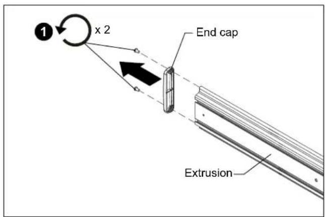
Figure 3
- Insert four 5/16-18 x 3/8" button head cap screws (D) into the two slot nuts (C) and partially tighten. (See Figure 4)
- Slide two slot nuts (C) into end of extrusion. (See Figure 4)
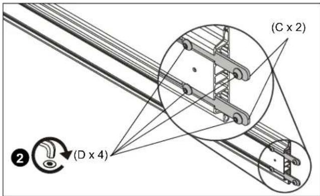
Figure 4

CAUTION: The storage panel must be mounted with the clip at the bottom. (See Figure 1) and (See Figure 5)
- Hold the storage panel (G) over the four button head screws (D) and lower the storage panel keyholes over the screws. (See Figure 5)
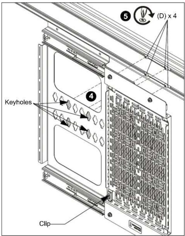
Figure 5
- Tighten screws securely against the storage panel.
Attaching Components
- Remove mounting plate from storage panel by pressing inward on the clip located at the bottom of the storage panel. (See Figure 6)
- Place component(s) on mounting plate and position in the desired location with the hole pattern in mounting plate best aligned to component mounting holes. (See Figure 6)
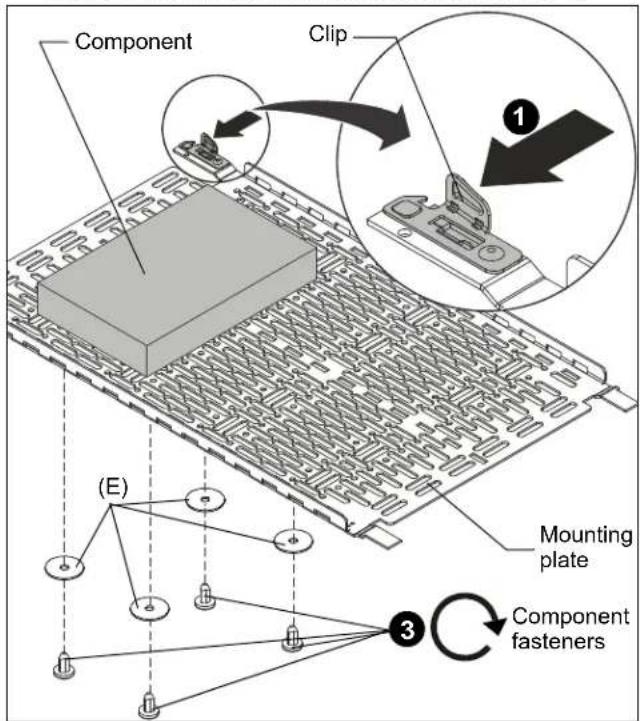
Figure 6
- Using the fasteners provided with the component and the washers (E), attach the component to the mounting plate. (See Figure 6)
- Return mounting plate to storage panel by installing the side without the clip into the panel first, followed by the side with the clip until it clicks into place. (See Figure 7)
- OPTIONAL: If desired, install plastic rivet (F) into hole next to clip to secure the mounting plate in place.(See Figure 7)
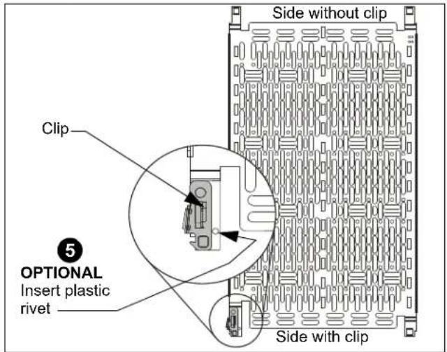
Figure 7

CHIEF®
A brand of legrand
8800-003122 Rev02
©2019 Legrand | AV
www.legrandav.com
07/19
USA/International A 6436 City West Parkway, Eden Prairie, MN 55344
P 800.582.6480 / 952.225.6000
F 877.894.6918 / 952.894.6918
Europe A Franklinstraat 14, 6003 DK Weert, Netherlands
P +31 (0) 495 580 852
F +31 (0) 495 580 845
Asia Pacific A Office No. 918 on 9/F, Shatin Galleria
18-24 Shan Mei Street
Fotan, Shatin, Hong Kong
P 852 2145 4099
F 852 2145 4477


Brand : Chief
Model : CSSMP15X10
Category : Unknown