
FCA820V - Video Conferencing System Chief - Free user manual and instructions
Find the device manual for free FCA820V Chief in PDF.

| Product Type | Video Conferencing Camera Mount & Accessory Shelf |
| Brand | Chief |
| Model | FCA820V |
| Category | Video Conferencing System |
| Compatibility | Windows 7, 8, 8.1 or higher; Mac OS X 10.7 or higher; Intel Core 2 Duo 2.4GHz, 2GB RAM, USB 2.0 |
| Mounting Type | Cart, Ceiling, Wall, or FCA800/801/810/811 Shelves |
| Dimensions (approx.) | 10 x 6 x 2 inches (254 x 152 x 51 mm) |
| Weight (approx.) | 2.0 lbs (0.9 kg) |
| USB Ports | 4-Port USB 3.0 Hub |
| Included Camera | Logitech Webcam C930e (compatible) |
| Included Speaker Phone | Yes |
| Cable Length | 10 ft (3 m) USB cable; optional CAT5 extension for VE model |
| USB Gender Changer | Included (FCA820V only) |
| USB Extender (Cat5) | Included (FCA820VE model) |
| Camera Height Adjustment | Yes, via two screws |
| Software Requirement | Latest Skype or comparable video conferencing app; milestone.com for latest compatibility |
| Installation Tools Required | Hex-Head Wrench, Phillips Screwdriver, Open-Ended Wrench |
| Material | Steel, Aluminum |
| Color | Black |
| Warranty | 1 Year (typical) |
| Safety Certifications | Indoor use only; not for TVs or monitors |
Frequently Asked Questions - FCA820V Chief
User questions about FCA820V Chief
0 question about this device. Answer the ones you know or ask your own.
Ask a new question about this device
Download the instructions for your Video Conferencing System in PDF format for free! Find your manual FCA820V - Chief and take your electronic device back in hand. On this page are published all the documents necessary for the use of your device. FCA820V by Chief.
USER MANUAL FCA820V Chief
INSTALLATION INSTRUCTIONS
Fusion™ Center Accessory Shelf
DISCLAIMER
Milestone AV Technologies and its affiliated corporations and subsidiaries (collectively "Milestone"), intend to make this manual accurate and complete. However, Milestone makes no claim that the information contained herein covers all details, conditions or variations, nor does it provide for every possible contingency in connection with the installation or use of this product. The information contained in this document is subject to change without notice or obligation of any kind. Milestone makes no representation of warranty, expressed or implied, regarding the information contained herein. Milestone assumes no responsibility for accuracy, completeness or sufficiency of the information contained in this document.
Chief® is a registered trademark of Milestone AV Technologies. All rights reserved.
DEFINITIONS
MOUNTING SYSTEM: A MOUNTING SYSTEM is the primary Chief product to which an accessory and/or component is attached.
ACCESSORY: AN ACCESSORY is the secondary Chief product which is attached to a primary Chief product, and may have a component attached or setting on it.
COMPONENT: A COMPONENT is an audiovisual item designed to be attached or resting on an accessory or mounting system such as a video camera, CPU, screen, display, projector, etc.

WARNING: A WARNING alerts you to the possibility of serious injury or death if you do not follow the instructions.

CAUTION: A CAUTION alerts you to the possibility of damage or destruction of equipment if you do not follow the corresponding instructions.

IMPORTANT SAFETY INSTRUCTIONS

WARNING: Failure to read, thoroughly understand, and follow all instructions can result in serious personal injury, damage to equipment, or voiding of factory warranty! It is the installer's responsibility to make sure all mounting systems are properly assembled and installed using the instructions provided.

WARNING: Use this mounting system only for its intended use as described in these instructions. Do not use attachments not recommended by the manufacturer.

WARNING: Never operate this mounting system if it is damaged. Return the mounting system to a service center for examination and repair.

WARNING: Do not use this product outdoors.

WARNING: RISK OF INJURY TO PERSONS! Do not use this mounting system to support video equipment such as televisions or computer monitors.
IMPORTANT ! : Make sure the system meets the following requirements.
- Windows® 7, 8, 8.1 or higher
• Mac OS® X 10.7 or higher
With:
• 2.4GHz Intel® Core 2 Duo Processor
- 2GB RAM or more
• USB 2.0 port (USB 3.0 ready)
NOTE: Refer to milestone.com for the latest software compatibility requirements.
--SAVE THESE INSTRUCTIONS--
DIMENSIONS
![FUSION WALL MOUNT SETUP 0.35 [8.9] MAX DISTANCE BETWEEN DISPLAYS 4,81 [122.1] 9.81 [249.2] OVERALL WIDTH 0.50 [12.7] MAX ABOVE EXTENSION 0.87 [22.2] CENTER OF MOUNT 0.50 [12.7] MAX BELOW EXTENSION 1.62 [41.1] 7.51 [190.8] OVERALL MAX 5,50 [139.8] OVERALL MIN 3.22 [81.9] MIN CAMERA DEPTH* 5.23 [132.9] MAX CAMERA DEPTH* (*)NOTES: TYPICAL FUSION INTERFACES ARE 0.625' [15.9] DEEP* FUSION CEILING/CART MOUNT SETUP 0.35 [8.9] MAX DISTANCE BETWEEN DISPLAYS 4,81 [122.1] 7.88 [200.0] OVERALL WIDTH 0.50 [12.7] MAX ABOVE EXTENSION 0.87 [22.2] CENTER OF MOUNT 1.62 [41.1] 7.51 [190.8] OVERALL MAX 5,50 [139.8] OVERALL MIN 3.23 [81.9] MIN CAMERA DEPTH* 5.23 [132.8] MAX CAMERA DEPTH* *NOTES: • FCA623 DUAL MONITOR INTERFACES ARE 1.4" DEEP](/content/2026/06/1218850/images/bc77062aac3710891fa68f606f261a249f3bcde23648f4d2b6d080af8817c1de.jpg)
DIMENSIONS (CONTINUED)
![FUSION CEILING/CART MOUNT WITH FCA8XX SERIES ABOVE OR BELOW SHELF SETUP 0.35 [8.9] MAX DISTANCE BETWEEN DISPLAYS 4.81 [122.1] 2.88 [73.0] OVERALL WIDTH 0.50 [12.7] MAX ABOVE EXTENSION 0.52 [13.2] *NOTES: • FCA623 DUAL MONITOR INTERFACES ARE 1.4" DEEP 7.52 [191.1] OVERALL MAX 5.51 [140.1] OVERALL MIN 3.24 [82.3] MIN CAMERA DEPTH* 1.62 [41.1] 5.24 [133.2] MAX CAMERA DEPTH*](/content/2026/06/1218850/images/c9b4e26c2f28625e2080243c98ab5c438ea6aeac124f05927c91f6814c2f8d7b.jpg)
LEGEND
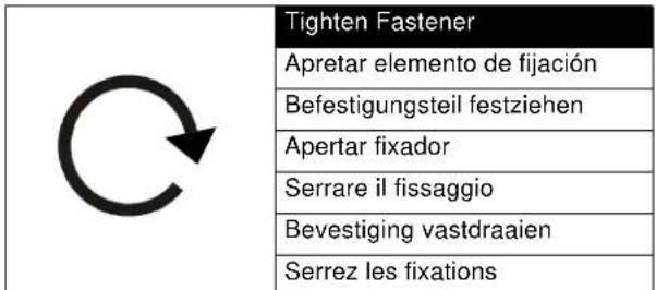 | |
| Loosen Fastener | |
| Aflojar elemento de fijación | |
| Befestigungsteil lösen | |
| Desapertar fixador | |
| Allentare il fissaggio | |
| Bevestiging losdraaien | |
| Desserrez les fixations | |
| Hex-Head Wrench | |
| Llave de cabeza hexagonal | |
| Sechskantschlüssel | |
| Chave de cabeça sextavada | |
| Chiave esagonale | |
| Zeskantsleutel | |
| Clé à tête hexagonale | |
| Phillips Screwdriver | |
| Destornillador Phillips | |
| Kreuzschlitzschraubendreher | |
| Chave de fendas Phillips | |
| Cacciavite a stella | |
| Kruiskopschroevendraaier | |
| Tournevis à pointe cruciforme |
| Open-Ended Wrench | |
| Llave de boca | |
| Gabelschlüssel | |
| Chave de bocas | |
| Chiave a punte aperte | |
| Steeksleutel | |
| Clé à fourche |
| Loosen Fastener | |
| Aflojar elemento de fijación | |
| Befestigungsteil lösen | |
| Desapertar fixador | |
| Allentare il fissaggio | |
| Bevestiging losdraaien | |
| Desserrez les fixations |
| Hex-Head Wrench | |
| Llave de cabeza hexagonal | |
| Sechskantschlüssel | |
| Chave de cabeça sextavada | |
| Chiave esagonale | |
| Zeskantsleutel | |
| Clé à tête hexagonale |
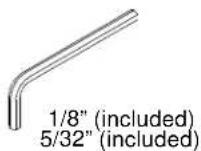
TOOLS REQUIRED FOR INSTALLATION


2
PARTS

A (1)
[FCA820V/VE camera mount]
natural_image
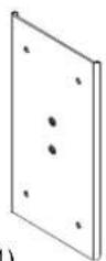
Technical line drawing of a mechanical bracket or clamp (no text or symbols)B (1)
[Center plate]
C (4)
1/4-20 x 3/8"
D (2)
10-32 x 1/4"
E (4) 1/4-20 x 1 1/4"

natural_image
Technical line drawing of a metal bracket component (no text or symbols)G (4) 1/4" H (2)
10
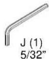
K (1)
1/8"

L (1)
[USB gender changer]
(820V model only)
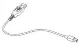
natural_image
Line drawing of a USB cable with connector port (no text or symbols)M (1) [10' USB cable]

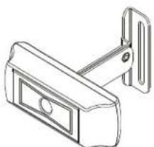
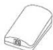
natural_image
Line drawing of a laboratory pipette with a circular dish and a test tube (no text or symbols)N (1) [Speaker phone]
P (1)
[USB-Cat5 extender box]
(820VE model only)
Q (1)
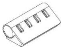
[4-port USB 3.0 hub]
ASSEMBLY AND INSTALLATION
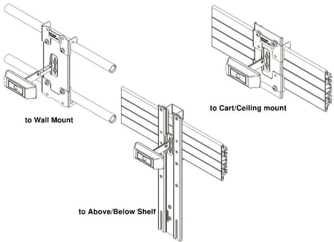
Installing to Cart/Ceiling Mount
NOTE: If installing to Wall Mount, proceed to "Installing to Wall Mount" Section. If installing to an FCA800/801 or FCA810/811 shelf, proceed to "Installing to FCA800/801/810/811 Shelves" section.
- Attach FCA820V/VE camera mount (A) to center plate (B) using two #10-32 x 1/4" button head cap screws (D) and two #10 washers (H). (See Figure 1)
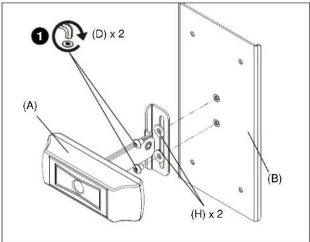
Figure 1
- Use two 1/4-20 x 3/8" button head cap screws (C) and two 1/4" washers (G) to attach one center holder (F) to center plate (B). (See Figure 2)
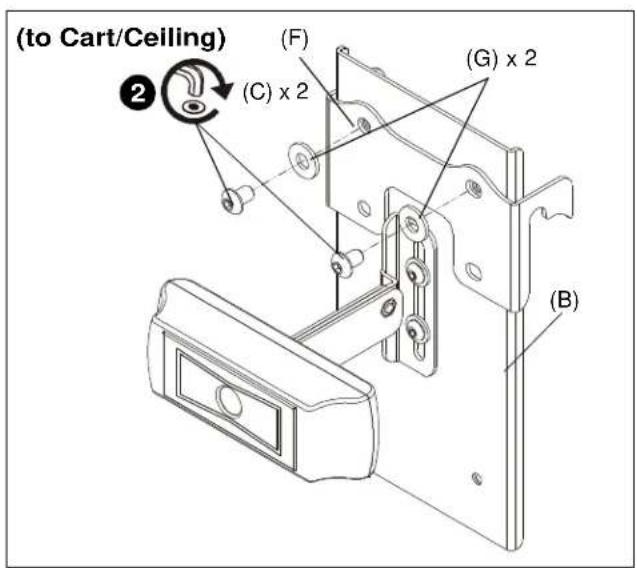
Figure 2
- Place center holder (F) on top of cart interface. (See Figure 3)
- Place second center holder (F) underneath cart interface so that mounting holes are aligned. (See Figure 3)

Figure 3
- Use two 1/4-20 x 3/8" button head cap screws (C) and two 1/4" washers (G) to attach the other center holder (F) to center plate (B). (See Figure 4)
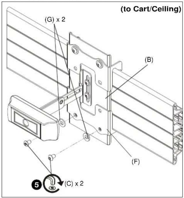
Figure 4
Installing to Wall Mount
- Attach FCA820V/VE camera mount (A) to center plate (B) using two #10-32 x 1/4" button head cap screws (D) and two #10 washers (H). (See Figure 5)
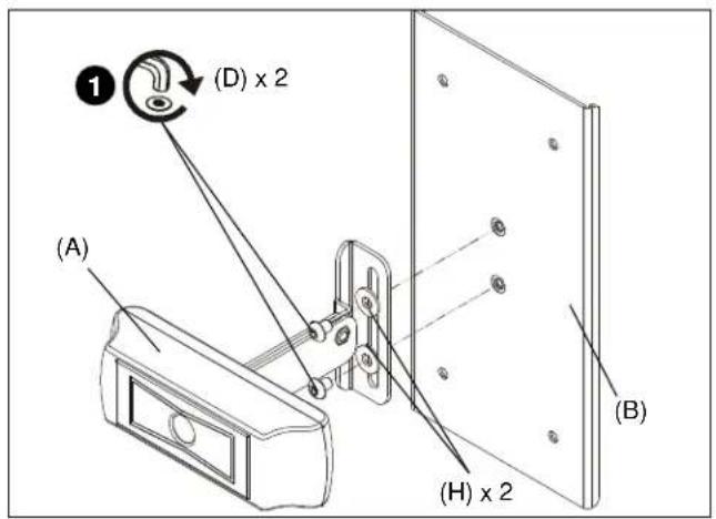
Figure 5
- Use two 1/4-20 x 1 1/4" button head cap screws (E) and two 1/4" washers (G) to partially attach one center holder (F) to center plate (B). Do NOT install screws too far or installation to wall mount will not be possible. (See Figure 6)

Figure 6
- Place center holder (F) on top of wall mount rail. (See Figure 7)
- Tighten two screws (E) holding center holder (F) to center plate (B). (See Figure 7)
- Place second center holder (F) underneath wall mount rail so that mounting holes are aligned. (See Figure 7)
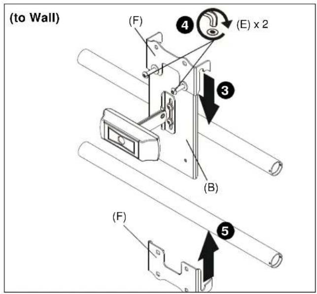
Figure 7
- Use two 1/4-20 x 1 1/4" button head cap screws (E) and two 1/4" washers (G) to attach the other center holder (F) to center plate (B). (See Figure 8)
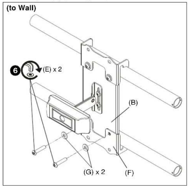
Figure 8
Installing to FCA800/801/810/811 Shelves
NOTE: FCA820V/VE may be attached to FCA800/801 or FCA810/811 Above/Below Shelves.
- Install FCA shelf to mount following FCA shelf installation instructions.
- Use two #10-32 x 1/4" button head cap screws (D) and two #10 washers (H) to secure FCA820V/VE camera mount (A) to FCA shelf main bracket. (See Figure 9)
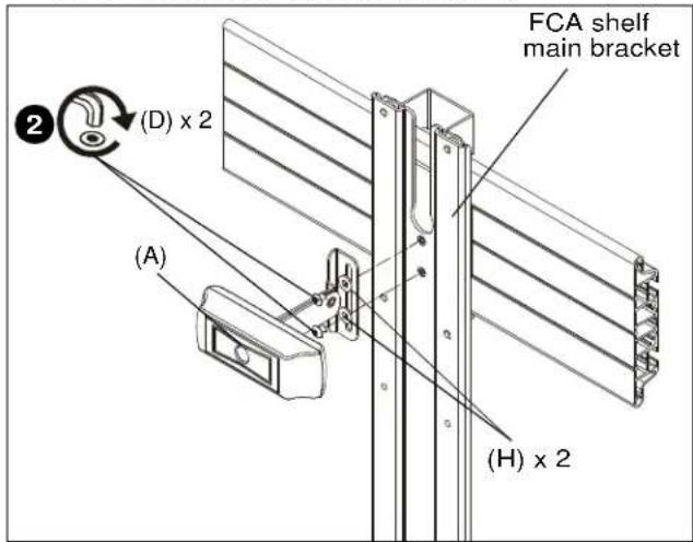
Figure 9
Camera Height Adjustment
- Loosen two screws (D) holding camera mount (A) to center plate (B). (See Figure 10)
- Adjust camera height to desired height. (See Figure 10)
- Tighten two screws (D) holding camera mount (A) to center plate (B). (See Figure 10)

Figure 10
Viewshare Installation
NOTE: Refer to milestone.com for the latest software compatibility requirements.
FCA820V
- Connect camera to USB gender changer (L) using USB cable supplied with camera. (See Figure 11)
- Connect USB gender changer (L) to 4-port USB hub (Q) using 10' USB cable (M). (See Figure 11)
- Connect speaker phone (N) to 4-port USB hub (Q) using USB cable supplied with speaker phone. (See Figure 11)
- Connect 4-port USB hub (Q) to computer using USB cable included with hub. (See Figure 11)
- Connect computer to display or projector. (See Figure 11)
- Verify the correct audio and video sources are selected in computer's settings (PC) or preferences (Mac). The camera will show up as "Logitech Webcam C930e."
- Download latest version of Skype or comparable video conferencing application.
FCA820VE
- Connect camera to USB extender box (P) using USB cable supplied with camera. (See Figure 11)
- Connect USB extender box (P) to second USB extender box using CAT5 cable (not included). (See Figure 11)
- Connect second USB extender box to 4-port USB hub (Q) using USB cable (M). (See Figure 11)
- Connect speaker phone (N) to 4-port USB hub (Q) using USB cable supplied with speaker phone (N). (See Figure 11)
- Connect 4-port USB hub (Q) to computer using USB cable included with hub. (See Figure 11)
- Connect computer to display or projector. (See Figure 11)
- Verify the correct audio and video sources are selected in computer's settings (PC) or preferences (Mac). The camera will show up as "Logitech Webcam C930e."
- Download latest version of Skype or comparable video conferencing application.
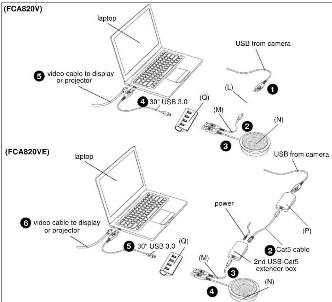
Figure 11

- INSTALLATION INSTRUCTIONS
- Fusion™ Center Accessory Shelf
- DISCLAIMER
- DEFINITIONS
- IMPORTANT SAFETY INSTRUCTIONS
- --SAVE THESE INSTRUCTIONS--
- TOOLS REQUIRED FOR INSTALLATION
- 2
- PARTS
- 10-32 x 1/4"
- 10
- ASSEMBLY AND INSTALLATION
- Installing to Cart/Ceiling Mount
- Installing to Wall Mount
- Installing to FCA800/801/810/811 Shelves
- Camera Height Adjustment
- Viewshare Installation
- FCA820V
- FCA820VE
Brand : Chief
Model : FCA820V
Category : Video Conferencing System