CoolScapes GBSR1P-GH - Fridge Delfield - Free user manual and instructions
Find the device manual for free CoolScapes GBSR1P-GH Delfield in PDF.

User questions about CoolScapes GBSR1P-GH Delfield
0 question about this device. Answer the ones you know or ask your own.
Ask a new question about this device
Download the instructions for your Fridge in PDF format for free! Find your manual CoolScapes GBSR1P-GH - Delfield and take your electronic device back in hand. On this page are published all the documents necessary for the use of your device. CoolScapes GBSR1P-GH by Delfield.
USER MANUAL CoolScapes GBSR1P-GH Delfield
Series GC, GB & GBS Reach-Ins CoolScapes™
Original Instructions Installation, Operation and Maintenance Manual
This manual is updated as new information and models are released. Visit our website for the latest manual.
natural_image
Exterior view of a modern stainless steel laboratory cabinet with two glass doors (no visible text or symbols)Safety Notices
▲Warning
Read this manual thoroughly before operating, installing or performing maintenance on the equipment. Failure to follow instructions in this manual can cause property damage, injury or death.
! DANGER
Do not install or operate equipment that has been misused, abused, neglected, damaged, or altered/modified from that of original manufactured specifications.
! DANGER
Keep power cord AWAY from HEATED surfaces. DO NOT immerse power cord or plug in water. DO NOT let power cord hang over edge of table or counter.
! DANGER
All utility connections and fixtures must be maintained in accordance with Local and national codes.
▲Warning
Authorized Service Representatives are obligated to follow industry standard safety procedures, including, but not limited to, local/national regulations for disconnection / lock out / tag out procedures for all utilities including electric, gas, water and steam.
▲Warning
Do not store or use gasoline or other flammable vapors or liquids in the vicinity of this or any other appliance. Never use flammable oil soaked cloths or combustible cleaning solutions, for cleaning.
▲Warning
This product contains chemicals known to the State of California to cause cancer and/or birth defects or other reproductive harm. Operation, installation, and servicing of this product could expose you to airborne particles of glasswool or ceramic fibers, crystalline silica, and/or carbon monoxide. Inhalation of airborne particles of glasswool or ceramic fibers is known to the State of California to cause cancer. Inhalation of carbon monoxide is known to the State of California to cause birth defects or other reproductive harm.
▲Warning
Do not use electrical appliances or accessories other than those supplied by the manufacturer.
▲Warning
Use caution when handling metal surface edges of all equipment.
▲Warning
This appliance is not intended for use by persons (including children) with reduced physical, sensory or mental capabilities, or lack of experience and knowledge, unless they have been given supervision concerning use of the appliance by a person responsible for their safety. Do not allow children to play with this appliance.
Caution
Use caution handling, moving and use of the R290 refrigerators to avoid either damaging the refrigerant tubing or increasing the risk of a leak. Components shall be replaced with like components. Servicing shall be done by a factory authorized service personnel to minimize the risk of possible ignition due to incorrect parts or improper service.
Notice
Proper installation, care and maintenance are essential for maximum performance and trouble-free operation of your equipment. Visit our website www.mtwkitchencare.com for manual updates, translations, or contact information for service agents in your area.
Table of Contents
Section 1 General Information
Model Numbers......4
Serial Number Information ....4
Warranty Information 4
Regulatory Certifications 4
Section 2 Installation
Location 5
Weight of Equipment 6
Clearance Requirements......6
Dimensions....7
Electrical Service 8
Voltage 8
Fuse/Circuit Breaker 8
Ground Fault Circuit Interrupter....8
Rated Amperages, Horsepower, Voltage & Power Cord Chart....8
Drain Connections....9
Heat of Rejection....9
Leveling....10
Stabilizing....10
Leg & Caster Installation....10
Reversible Door Instructions....11
Applicable to Full Door Better Models 11
Pilaster Clip Kit Installation Instructions....12
Applicable to GC Models....12
New Bottom Hinge Cartridge Installation....13
T-1 Tray Slide Installation 14
T-2 Tray Slide Installation 15
T-3 Tray Slide Installation 16
T-4 Rack Slide Installation 17
Section 3 Operation
R290 Controls/Programming/Settings....19
R290 Temperature Control & Display 20
R290 Evaporator Fan Operation....21
R290 Changing Display from Fahrenheit to Celsius on ERC112 Control....22
Section 4 Maintenance
Cleaning and Sanitizing Procedures....23
General....23
Interior Cleaning....24
Exterior Cleaning 24
Drain....25
Cleaning the Condenser Coil 25
Casters 25
Doors/Hinges 25
Preventing Blower Coil Corrosion 25
Section 5 Troubleshooting
Problem -> Cause -> Correction Chart....27
Section 1
General Information
Model Numbers
This manual covers the following models:
| 1 Section Refrigerators |
| Glass Doors Solid Doors |
| GBR1P-G(H) GBR1P-S(H) |
| GBSR1P-G(H) GBSR1P-$(H) |
| GCR1P-G(H) GCR1P-S(H) |
| 2 Section Refrigerators |
| Glass Doors Solid Doors |
| GBR2P-G(H) GBR2P-S(H) |
| GBSR2P-G(H) GBSR2P-$(H) |
| GCR2P-G(H) GCR2P-S(H) |
| 3 Section Refrigerators |
| Glass Doors Solid Doors |
| GBR3P-G(H) GBR3P-S(H) |
| GBSR3P-G(H) GBSR3P-$(H) |
| GCR3P-G(H) GCR3P-S(H) |
| Solid Doors Freezers | |
| 1 Section 2 Section 3 Section | |
| GBF1P-S(H) GBF2P-S(H) GBF3P-S(H) | |
| GBSF1P-S(H) GBSF2P-S(H) GBSF3P-S(H) | |
| GCF1P-S(H) GCF2P-S(H) GCF3P-S(H) | |
Serial Number Information
The serial number is on the identification plate that also includes the model number. The identification plate is located near the top front corner of the left interior wall.
Always have the serial number of your unit available when calling for parts or service.
Warranty Information
Visit
http://www.delfield.com/warranty to:
- Register your product for warranty.
- Verify warranty information.
• View and download a copy of your warranty.
Regulatory Certifications
Models are certified by:
NSF National Sanitation Foundation (NSF)
• UL Underwriters Laboratories (UL)
• cUL Underwriters Laboratories of Canada (cUL)
Section 2 Installation
! DANGER
Installation must comply with all applicable fire and health codes in your jurisdiction.
! DANGER
Use appropriate safety equipment during installation and servicing.
▲Warning
Do not damage the refrigeration circuit when installing, maintaining or servicing the unit.
Location
▲Warning
This equipment must be positioned so that the plug is accessible unless other means for disconnection from the power supply (e.g., circuit breaker or disconnect switch) is provided.
▲Warning
Adequate means must be provided to limit the movement of this appliance without depending on or transmitting stress to the electrical conduit or gas lines.
▲Warning
To avoid instability the installation area must be capable of supporting the combined weight of the equipment and product. Additionally the equipment must be level side to side and front to back.
▲Warning
This equipment is intended for indoor use only. Do not install or operate this equipment in outdoor areas.
The location selected for the equipment must meet the following criteria. If any of these criteria are not met, select another location.
- The location MUST be level, stable and capable of supporting the weight of the equipment.
- The location MUST be free from and clear of combustible materials.
- Equipment MUST be level both front to back and side to side.
- Position the equipment so it will not tip or slide.
- Front casters MUST be locked once positioned.
- Recommended air temperature is 60^ - 100^ (16^ - 38^) .
- Proper air supply for ventilation is REQUIRED AND CRITICAL for safe and efficient operation. Refer to Clearance Requirements chart on page 6.
- Do not obstruct the flow of ventilation air. Make sure the air vents of the equipment are not blocked.
- Do not install the equipment directly over a drain. Steam rising up out of the drain will adversely affect operation, air circulation, and damage electrical / electronic components.
Weight of Equipment
| Description Models Weight | ||
| 1 Section Refrigerators | ||
| Glass Doors GBR1P-G(H),GBSR1P-G(H),GCR1P-G(H) | 236 lbs (107 kg) | |
| Solid Doors GBR1P-S(H) 312 lbs (142 kg) | ||
| GBSR1P-S(H) 351 lbs (159 kg) | ||
| GCR1P-S(H) 282 lbs (128 kg) | ||
| 2 Section Refrigerators | ||
| Glass Doors GBR2P-G(H),GBSR2P-G(H),GCR2P-G(H) | 322 lbs (146 kg) | |
| Solid Doors GBR2P-S(H),GBSR2P-S(H) | 495 lbs (225 kg) | |
| GCR2P-S(H) 430 lbs (195 kg) | ||
| 3 Section Refrigerators | ||
| Glass Doors GBR3P-G,GBSR3P-G,GCR3P-G | 485 lbs (220 kg) | |
| Solid Doors GBR3P-S(H) 727 lbs (330 kg) | ||
| GBSR3P-S(H) 767 lbs (348 kg) | ||
| GCR3P-S(H) 668 lbs (303 kg) | ||
| 1 Section Freezers | ||
| Solid Doors GBF1P-S(H) 336 lbs (152 kg) | ||
| GBSF1P-S(H) 354 lbs (161 kg) | ||
| GCF1P-S(H) 299 lbs (136 kg) | ||
| 2 Section Freezers | ||
| Solid Doors GBF2P-S(H) 532 lbs (241 kg) | ||
| GBSF2P-S(H) 495 lbs (225 kg) | ||
| GCF2P-S(H) 445 lbs (202 kg) | ||
| 3 Section Freezers | ||
| Solid Doors GBF3P-S(H),GBSF3P-S(H) | 772 lbs (350 kg) | |
| GCF3P-S(H) 707 lbs (321 kg) | ||
Clearance Requirements
| ⚠ DANGER |
| Minimum clearance requirements are the same for noncombustible locations as for combustible locations. The flooring under the appliance must be made of a noncombustible material. |
| ⚠️ DANGER |
| Risk of fire/shock. All minimum clearances must be maintained. Do not obstruct vents or openings. |
| Top |
| 12.00" (305mm) |
- Keep the vents clean and free of obstruction.
- Casters or optional legs must be used and not removed.
Dimensions
| Model Length | Depth Height | ||
| 1 Section Refrigerators | |||
| GBR1P-G(H),GBR1P-S(H),GBSR1P-G(H),GBSR1P-S(H),GCR1P-G(H),GCR1P-S(H) | 27.34"(70cm) | 32.44"(82cm) | 79.50"(202cm) |
| 2 Section Refrigerators | |||
| GBR2P-G(H),GBR2P-S(H),GBSR2P-G(H),GBSR2P-S(H),GCR2P-G(H),GCR2P-S(H) | 55.16"(140cm) | 32.44"(82cm) | 79.50"(202cm) |
| 3 Section Refrigerators | |||
| GBR3P-G,GBR3P-S(H),GBSR3P-G,GBSR3P-S(H),GCR3P-G,GCR3P-S(H), | 82.97"(211cm) | 32.44"(82cm) | 79.50"(202cm) |
| 1 Section Freezers | |||
| GBF1P-S(H),GBSF1P-S(H),GCF1P-S(H) | 27.34"(70cm) | 32.44"(82cm) | 79.50"(202cm) |
| 2 Section Freezers | |||
| GBF2P-S(H),GBSF2P-S(H),GCF2P-S(H) | 55.16"(140cm) | 32.44"(82cm) | 79.50"(202cm) |
| 3 Section Freezers | |||
| GBF3P-S(H),GBSF3P-S(H),GCF3P-S(H) | 82.97"(211cm) | 32.44"(82cm) | 79.50"(202cm) |
| Model Volume | |
| 1 Section Refrigerators | |
| GBR1P-G(H),GBR1P-S(H),GBSR1P-G(H),GBSR1P-S(H),GCR1P-G(H),GCR1P-S(H) | 21ft^3 (595L) |
| 2 Section Refrigerators | |
| GBR2P-G(H),GBR2P-S(H),GBSR2P-G(H),GBSR2P-S(H),GCR2P-G(H),GCR2P-S(H) | 46ft^3 (1303L) |
| 3 Section Refrigerators | |
| GBR3P-G,GBR3P-S(H),GBSR3P-G,GBSR3P-S(H),GCR3P-G,GCR3P-S(H), | 71ft^3 (2010L) |
| 1 Section Freezers | |
| GBF1P-S(H),GBSF1P-S(H),GCF1P-S(H) | 21ft^3 (595L) |
| 2 Section Freezers | |
| GBF2P-S(H),GBSF2P-S(H),GCF2P-S(H) | 46ft^3 (1303L) |
| 3 Section Freezers | |
| GBF3P-S(H),GBSF3P-S(H),GCF3P-S(H) | 71ft^3 (2010L) |
Electrical Service
DANGER
Check all wiring connections, including factory terminals, before operation. Connections can become loose during shipment and installation.
▲Warning
This appliance must be grounded and all field wiring must conform to all applicable local and national codes. Refer to rating plate for proper voltage. It is the responsibility of the end user to provide the disconnect means to satisfy the authority having jurisdiction.
VOLTAGE
All electrical work, including wire routing and grounding, must conform to local, state and national electrical codes.
The following precautions must be observed:
• The equipment must be grounded.
- A separate fuse/circuit breaker must be provided for each unit.
- Check all green ground screws, cables and wire connections to verify they are tight before start-up.
FUSE/CIRCUIT BREAKER
A separate fuse/circuit breaker must be provided for each unit.
GROUND FAULT CIRCUIT INTERRUPTER
Ground Fault Circuit Interrupter (GFCI/GFI) protection is a system that shuts down the electric circuit (opens it) when it senses an unexpected loss of power, presumably to ground. Manitowoc does not recommend the use of GFCI/GFI circuit protection to energize our equipment. If code requires the use of a GFCI/GFI then you must follow the local code. The circuit must be dedicated, sized properly and there must be a panel GFCI/GFI breaker. We do not recommend the use of GFCI/GFI outlets to energize our equipment as they are known for more intermittent nuisance trips than panel breakers.
RATED AMPERAGES, HORSEPOWER, VOLTAGE & POWER CORD CHART
Maximum 10ft (3m) cord with plug.
| Glass Door Models | Solid Door Models Amps HP Voltage, Cycle, Phase NEMA Plug | |||||
| Refrigerators | 1 Section | GBR1P-G(H), GBSR1P-G(H), GCR1P-G(H) | GBR1P-S(H), GBSR1P-S(H), GCR1P-S(H) | 4.2 0.22 1 | 15, 60, 1 5-15p | |
| 2 Section | GBR2P-G(H), GBSR2P-G(H), GCR2P-G(H) | GBR2P-S(H), GBSR2P-S(H), GCR2P-S(H) | 6.0 0.33 1 | 15, 60, 1 5-15p | ||
| 3 Section | GBR3P-G, GBSR3P-G, GCR3P-G | GBR3P-S(H), GBSR3P-S(H), GCR3P-S(H) | 6.5 0.355 | 11 | 5, 60, 1 5-15p | |
| Freezers | 1 Section | NA | GBF1P-S(H), GBSF1P-S(H), GCF1P-S(H) | 7.2 0.55 1 | 15, 60, 1 5-15p | |
| 2 Section | NA | GBF2P-S(H), GBSF2P-S(H), GCF2P-S(H) | 10.0 0.68 | 15, 60, 1 5-15p | ||
| 3 Section | NA | GBF3P-S(H), GBSF3P-S(H), GCF3P-S(H) | 14.7 | 0.55 (x2) | 115, 60, 1 5-20P | |
Drain Connections
| ▲Warning Moisture collecting from improper drainage can create a slippery surface on the floor and a hazard to employees. It is the owner's responsibility to provide a container or outlet for drainage. |
Refrigeration
| Model | BTU/Hour Capacity | Heat of Rejection (BTU) | Charge | |
| 1 Section Refrigerators | ||||
| Glass | Full Height DoorsGBR1P-G,GBSR1P-G,GCR1P-G | 1920 490 | 113g | |
| Half Height DoorsGBR1P-GH,GBSR1P-GH,GCR1P-GH | 1920 540 | 113g | ||
| Solid | Full Height DoorsGBR1P-S,GBSR1P-S,GCR1P-S | 1920 385 | 113g | |
| Half Height DoorsGBR1P-SH,GBSR1P-SH,GCR1P-SH | 1920 400 | 113g | ||
| 2 Section Refrigerators | ||||
| Glass | Full Height DoorsGBR2P-G,GBSR2P-G,GCR2P-G | 2540 780 | 113g | |
| Half Height DoorsGBR2P-GH,GBSR2P-GH,GCR2P-GH | 2540 880 | 113g | ||
| Solid | Full Height DoorsGBR2P-S,GBSR2P-S,GCR2P-S | 2540 565 | 113g | |
| Half Height DoorsGBR2P-SH,GBSR2P-SH,GCR2P-SH | 2540 590 | 113g | ||
| 3 Section Refrigerators | ||||
| Glass | Full Height DoorsGBR3P-G,GBSR3P-G,GCR3P-G | 3865 1175 | 118g | |
| Model | BTU/Hour Capacity | Heat of Rejection (BTU) | Charge | |
| Solid | Full Height DoorsGBR3P-S,GBSR3P-S,GCR3P-S | 3865 850 | 118g | |
| Half Height DoorsGBR3P-SH,GBSR3P-SH,GCR3P-SH | 3865 895 | 118g | ||
| 1 Section Freezers | ||||
| Solid | Full Height DoorsGBF1P-S,GBSF1P-S,GCF1P-S | 2035 760 | 93g | |
| Half Height DoorsGBF1P-SH,GBSF1P-SH,GCF1P-SH | 2035 790 | 93g | ||
| 2 Section Freezers | ||||
| Solid | Full Height DoorsGBF2P-S,GBSF2P-S,GCF2P-S | 2485 1275 | 109g | |
| Half Height DoorsGBF2P-SH,GBSF2P-SH,GCF2P-SH | 2485 1340 | 109g | ||
| 3 Section Freezers | ||||
| Solid | Full Height DoorsGBF3P-S,GBSF3P-S,GCF3P-S | 4065 1700 | 109g/system | |
| Half Height DoorsGBF3P-SH,GBSF3P-SH,GCF3P-SH | 4065 1795 | 109g/system | ||
Leveling
After the cabinet has been placed in the desired location, cabinets with legs must be leveled. Level units from front to back and from side to side. Leveling will insure proper door operation and removal of condensate. Cabinets with casters must have the caster brake set so the cabinet cannot move.
Stabilizing
It is very important that all legs are properly adjusted to keep the cabinet level, evenly distribute the weight and to make sure the unit will not rock, lean or be unstable.
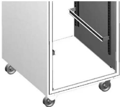
Leg & Caster Installation
DANGER
Legs or casters must be installed and the legs or casters must be screwed in completely to prevent bending. When casters are installed the mass of this unit will allow it to move uncontrolled on an inclined surface. These units must be tethered/secured to comply with all applicable codes.
▲Warning
The unit must be installed in a stable condition with the front wheels locked. Locking the front casters after installation is the owner's and operator's responsibility.
▲Warning
Use a jack to lift the refrigeration unit off the ground just far enough to remove the leg/caster. Place blocking underneath the unit. Do not work underneath a raised unit without proper blocking. Do not lift the unit more than necessary to remove the leg/caster. Lifting the unit too far can make the unit unstable.
Caution
All single-section units require that the swivel casters be mounted on the front and rigid casters be mounted on the rear.
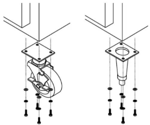
To install the legs or casters:
- Remove unit from skid.
NOTE: The bolts used to hold the unit to the skid should be re-used as the fourth hex head bolt for each caster or leg plate installation. The bolt should not measure over 2" (5cm) in length.
-
Raise unit to access leg/caster mounting holes on bottom of unit.
-
Attach the legs or casters to bottom of cabinet using hex head bolts.
natural_image
Technical line drawing of a mechanical assembly with two views (top and side), showing internal components and mounting holes (no text or symbols)Shelf Installation
APPLICABLE TO GC MODELS
- If the shelves are attached to the shelf pins, detach the shelves and set them aside. Cut zip ties if necessary.
- Tighten the shelf pins to the refrigerator side walls and mullions.
Caution
Shelf pins can be become damaged and unusable if shelves are loaded while the pins are loose.
- Place the shelves back on the pins.
natural_image
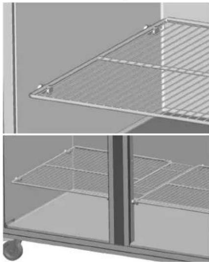
Exterior view of a modern office building (no signage)APPLICABLE TO GB MODELS
- Insert the clips into the pilaster holes at the desired shelf heights.

natural_image
Interior view of a room with two doors and vertical supports (no text or symbols visible)- Set the shelves on the clips.

natural_image
Architectural detail showing two views of a metal grate structure (no text or symbols)Reversible Door Instructions
APPLICABLE TO FULL DOOR BETTER MODELS
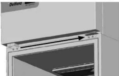
- Open the door.
- Remove two bolts securing the hinge bracket above the door.
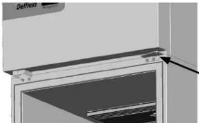
natural_image
Close-up of a Delfield refrigerator interior showing glass door and front panel (no text or symbols visible)-
Lift the door up and out.
-
Save the hinge bracket.
-
Remove the door lock and move it to the other side. Use the original screws and the vacant hinge holes.
natural_image
Close-up of a Delfield air conditioner unit with a door and vent, showing airflow direction (no text or symbols)- Remove three bolts securing the hinge bracket to the bottom of the unit.
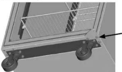
natural_image
3D rendering of a mechanical cart with wheels and a grid panel (no text or symbols visible)- Flip it over and install it on the opposite side.

natural_image
3D rendering of a mechanical cart with wheels and a grid, no visible text or symbols-
Rotate the door 180°.
-
Move the white nylon washer from the top hinge pin to the bottom hinge pin.
-
Insert the bottom hinge pin into the hinge bracket.

natural_image
Mechanical assembly diagram showing a rotating component with mounting holes and a central hub (no text or symbols)- Locate the provided alternate top hinge bracket.
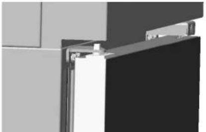
- Place the hinge bracket over the top hinge pin.
- Open the door.
- Using the original screws install the hinge bracket on the new side in the vacant lock holes.
natural_image
Exterior view of a modern office building (no signage)
natural_image
Pure electrical circuit lines without any symbols-
Check for proper closure and gasket seal.
-
Adjust hinges as needed.
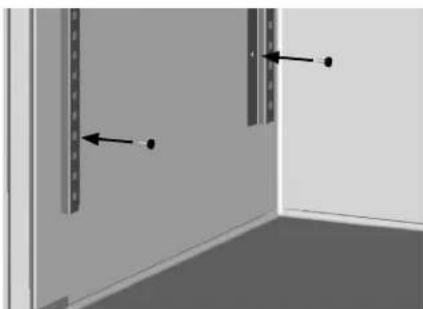
Pilaster Clip Kit Installation Instructions
APPLICABLE TO GC MODELS

natural_image
Exterior view of a modern office building (no signage)-
If the shelves are attached to the shelf pins, detach and set them aside. Cut zip ties if necessary.
-
Remove the shelf pins from refrigerator side walls and mullions. These holes will be used to mount the pilasters.
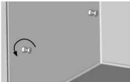
natural_image
Interior corner of a room with two wall-mounted sensors and a curved arrow indicating rotation (no text or symbols)- Match up the pilaster mounting holes with the refrigerator and mullion holes. Secure with provided screws.
natural_image
Interior corner of a room with two vertical panels and directional arrows indicating movement (no text or symbols)
natural_image
Exterior view of two rectangular metal enclosure units with vertical slats and a flat floor (no text or symbols)- Insert the clips into the pilaster holes at the desired shelf heights.

natural_image
Interior view of a room with three panels showing door, shelf, and door lock (no text or symbols visible)- Set the shelves on the clips.
natural_image
Architectural detail showing two views of a metal shelving unit with diagonal bracing and horizontal slats (no text or symbols)New Bottom Hinge Cartridge Installation
- Install the new cartridge into the door as received. The new cartridge will be in the CLOSED position.
natural_image
Close-up of a metallic mechanical component with a cylindrical rod inserted, showing no visible text or symbols.- As you unload the hinge tension be careful to hold on tight because you should feel the strong spring tension as you rotate the hinge. Place the hinge bracket on the square hinge pin and rotate it 12 turn to the outside of the door.

natural_image
Close-up of a hand holding a textured sleeve with a metal tool inserted (no visible text or symbols)- After the hinge has been rotated, it will now be in the OPEN position and NOT under spring tension.

natural_image
Close-up of a metallic tool with a triangular tip, possibly a mechanical component or tool, against a dark background (no visible text or symbols)- Mount the door back onto the cabinet with the door OPEN. The door should now close properly.
- Begin closing the door, the door should finish closing on it's own. If the door stays open remove the door and hinge bracket.
- Using the hinge bracket rotate the square peg on the cartridge until you feel tension and resistance if you move the hinge in either direction. The hinge is now in the CLOSED position. Repeat instructions starting with step 2.
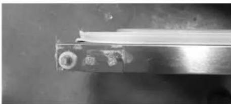
T-1 Tray Slide Installation
Edge Support for 18" x 26" pans
natural_image
Exterior view of a white industrial machine with wheels and internal compartments (no text or symbols visible)Installed T-1 Tray Slide for 18"x26"Pans
| System Name T-1 | |
| Slide Style Tray | |
| Support Style Edge | |
| Compatible with 12" x 20" Pans No | |
| Compatible with 18" x 26" Pans Yes |
The T-1 tray slide system is designed to support 18" x 26" pans by the edge of the pan. The slides are shaped as a C channel.
Each set of tray slides is mounted at the same height across a door section. If the tray slides are not at the same height, the pan cannot be held securely. For each pan, one set of two (2) tray slides is used. The only exception to this rule is when 1.5" pan spacing is desired. For 1.5" spacing, the tray slides are mounted every 3" and the top and bottom of each tray slide is used to hold a pan.
| Centers | ||||
| 1.5" 2.0" 3.0" 4.0" | 5.0" 6.0" | |||
| Maximum Tray Slides for a Full Section | ||||
| 17 26 17 13 10 8 | ||||
| Maximum Tray Slides for a Half Section (Top) | ||||
| 7 10 6 5 4 4 | ||||
| Maximum Tray Slides for a Half Section (Bottom) | ||||
| 8 12 8 6 5 4 | ||||
T-1 Installation Instructions
- For each pan, mount a pair of tray slides; one on each side of the door section at the same height. Mount the tray slides onto the pilasters by sliding the tray slide tabs down into the cutouts. Make sure that all tabs are engaged securely to each pilaster.
NOTE: A dead-blow hammer is recommended to seat the tab into the cutouts.
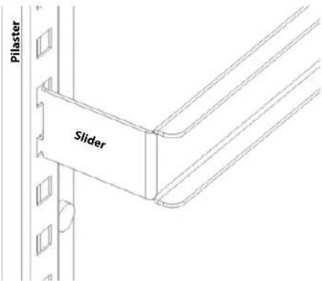
text_image
Pilaster Slider- Verify that all tray slides are lined up evenly.
NOTE: An easy check to verify correct installation is to slide an 18" x 26" pan onto each slide. If the pan is held securely, and is level inside the door section, the installation has been successful.
natural_image
Technical line drawing of two vertical metal frame structures with mounting holes (no text or symbols)T-2 Tray Slide Installation
Universal Bottom Support for 12" x 20" and 18" x 26" pans

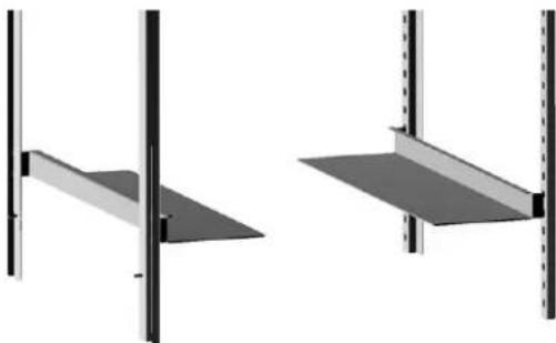
natural_image
Interior view of a stainless steel kitchen appliance with two empty bays (no text or symbols visible)Installed T-2 tray slide with both size pans
| System Name T-2 | |
| Slide Style Tray | |
| Support Style Bottom | |
| Compatible with 12" x 20" Pans Yes | |
| Compatible with 18" x 26" Pans Yes |
The T-2 (Universal) tray slide system is designed to support both 12" x 20" and 18" x 26" pans by the bottom. The tray slide is an L shaped piece of formed stainless steel.
Each set of tray slides is mounted at the same height across a door section. If the tray slides are not at the same height, the pan cannot be held securely. For each pan, one set of two (2) tray slides is used.
| Centers | |||
| 2.0" 3.0" 4.0" 5.0" 6.0" | |||
| Maximum Tray Slides for a Full Section | |||
| 25 17 12 10 8 | |||
| Maximum Tray Slides for a Half Section (Top) | |||
| 10 6 5 4 4 | |||
| Maximum Tray Slides for a Half Section (Bottom) | |||
| 10 6 6 5 4 | |||
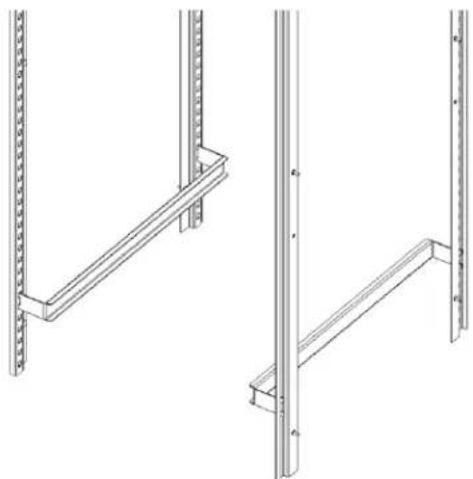
natural_image
Two identical architectural or structural diagrams showing vertical supports and a flat panel, with no text or symbols present.T-2 Tray Slide System
T-2 Installation Instructions
- For each pan, two (2) tray slides will be used. Each tray slide must have another tray slide at the same height, on the opposite side of the door section. Mount the tray slides onto the pilasters by sliding the tabs down into the pilaster cutouts. Make sure that all tabs are engaged securely to each pilaster.
NOTE: A dead-blow hammer is recommended to seat the tab into the cutouts.

text_image
Pilaster Slider- Verify that all tray slides are lined up evenly.
NOTE: An easy check to verify correct installation is to slide a pan onto each slide. If the pan is held securely, and is level inside the door section, the installation has been successful.
T-3 Tray Slide Installation
Edge Support for 12" x 20" pans
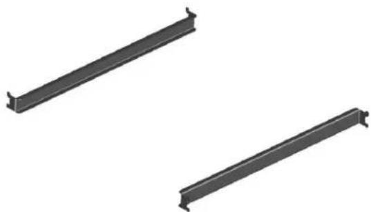
natural_image
Two black metal rod-like components with flanged ends, shown in side view (no text or symbols)T-3 Tray Slide for 12"x 20" pans
| System Name T-3 | |
| Slide Style Tray | |
| Support Style Edge | |
| Compatible with 12" x 20" Pans Yes | |
| Compatible with 18" x 26" Pans No |
The T-3 tray slide system is designed to support 12" x 20" pans by the edge of the pan. The slides are shaped as a C channel.
Each set of tray slides is mounted at the same height across a door section. If the tray slides are not at the same height, the pan cannot be held securely. For each pan, one set of two (2) tray slides is used.
| Centers | |||
| 3.0" 4.0" $ .0" 6.0" | |||
| Maximum Tray Slides for a Full Section | |||
| 17 12 9 7 | |||
| Maximum Tray Slides for a Half Section (Top) | |||
| 6 5 4 3 | |||
| Maximum Tray Slides for a Half Section (Bottom) | |||
| 8 6 5 4 | |||
T-3 Installation Instructions
- For each pan, two (2) tray slides will be used. Each tray slide must have another tray slide at the same height, on the opposite side of the door section. Mount the tray slides onto the pilasters by sliding the tabs down into the pilaster cutouts. Make sure that all tabs are engaged securely to each pilaster.
NOTE: A dead-blow hammer is recommended to seat the tab into the cutouts.

text_image
Pilaster Slider- Verify that all tray slides are lined up evenly.
NOTE: An easy check to verify correct installation is to slide a pan of the appropriate size into each slide. If the pan is held securely, and is level inside the door section, the installation has been successful.
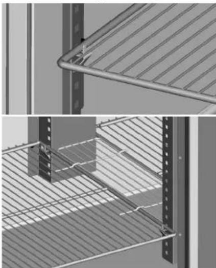
T-4 Rack Slide Installation
Edge Support for 18" x 26" pans

natural_image
Two identical metal structural panels with vertical supports and horizontal beams, shown from different angles (no text or symbols)Installed T-4 Tray Slide for 18"x 26" pan
| System Name T-4 | |
| Slide Style Rack | |
| Support Style Edge | |
| Compatible with 12" x 20" Pans No | |
| Compatible with 18" x 26" Pans Yes |
The T-4 rack slide system is designed to support 18" x 26" pans by the edge of the pan. The T-4 rack slide system consists mounting plates for each side, and a set of racks. The racks are formed of heavy gauge metal wire.
Each set of rack slides is mounted at the same height across a door section. If the rack slides are not at the same height, the pan cannot be held securely. Each rack uses two (2) mounting plates.
T-4 Installation Instructions
- Start assembling the mounting plates at the bottom of the door section. Place a bottom mounting plate so that each set of tabs engages a cutout on the pilaster. Push the mounting plate down to secure the plate to the cutouts.
NOTE: A dead-blow hammer is recommended to seat the tab into the cutouts.
-
On the same side place a top mounting plate with the bottom edge 20" (51cm) above the top of the lower mounting plate.
-
Repeat steps 1-2 on the opposite side. Verify that all mounting plates are lined up across the door section.
-
For a full section installation, repeat steps 1-3 for the upper half.
-
Place each rack on two (2) mounting plates.

text_image
Rack Mounting Plate Pilaster- Verify that all tray slides are lined up evenly.
NOTE: An easy check to verify correct installation is to slide a pan of the appropriate size into each slide. If the pan is held securely, and is level inside the door section, the installation has been successful.
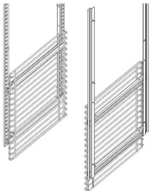
natural_image
Technical line drawings of two vertical metal shelving units with ribbed grilles (no text or symbols)Section 3
Operation
! DANGER
Do not operate any appliance with a damaged cord or plug. All repairs must be performed by a qualified service company.
! DANGER
Never stand on the unit! They are not designed to hold the weight of an adult, and may collapse or tip if misused in this manner.
▲Warning
Do not contact moving parts.
▲Warning
All covers and access panels must be in place and properly secured, before operating this equipment.
▲Warning
Do not use electrical appliances inside the food storage compartment of this appliance.
▲Warning
The operator of this equipment is solely responsible for ensuring safe holding temperature levels for all food items. Failure to do so could result in unsafe food products for customers.
▲Warning
Overloading shelves can damage equipment or cause bodily injury.
▲Warning
Damp or wet hands may stick to cold surfaces.
▲Warning
Do not block the supply and return air grills or the air space around the air grills. Keep plastic wrappings, paper, labels, etc. from being airborne and lodging in the grills. Failure to keep the air grills clear will result in unsatisfactory operation of the system.
Caution
Do not throw items into the storage area. Failure to heed this recommendation could result in damage to the interior of the cabinet or to the blower coil.
R290 Controls/Programming/Settings
R290 Refrigerator
Refrigerators are factory set at mid-range to maintain about 38^ F ( 3^ C) box temperature.
- At initial start-up or anytime power is disconnected, then reconnected to the unit, the control will go into defrost mode.
- The control will enter a DEFROST mode and the display will read dEF. The compressor and condenser fan as well as the evaporator fan will remain off until this initial defrost is complete. This initial defrost cycle may take up to 35 minutes to complete.
- The display will continue to read dEF for an additional 30 minutes while the cooling cycle cools the box to the set temperature.
- Then the digital thermostat will display box temperature.
- The temperature control will cycle the compressor, evaporator fan motor and condenser fan motor to maintain box temperature at the control setting. For more information see R290 Evaporator Fan Operation on page 21.
R290 Refrigerator Defrost
The temperature control also monitors the evaporator temperature and will turn off the compressor and condenser fan motor when needed to allow accumulated frost on the evaporator to clear. During this defrost cycle, the digital temperature display will read dEF. After the defrost cycle is complete, the temperature control will return to a normal cooling cycle, but the display will continue to read dEF until the evaporator returns to normal cooling temperatures (up to 30 minutes).
R290 Freezer
Freezers are factory set at mid-range to maintain about -2^ F ( -19^ C) box temperature.
- At initial start-up or anytime power is disconnected, then reconnected to the unit, the control will go into defrost mode
- The control will enter a DEFROST mode and the display will read dEF. The compressor and condenser fan as well as the evaporator fan will remain off until this initial defrost is complete. This initial defrost cycle may take up to 35 minutes to complete.
- The display will continue to read dEF for an additional 30 minutes while the freezing cycle cools the box to the set temperature.
- Then the thermostat will display box temperature.
- The temperature control will cycle the compressor, evaporator fan motor and condenser fan motor to maintain box temperature at the control setting. For more information see R290 Evaporator Fan Operation on page 21.
R290 Freezer Automatic Defrost
The control also monitors compressor total running time and will enter a defrost cycle after total compressor running time is greater than seven hours since the last defrost cycle OR if evaporator coil temperature drops below -30^ F ( -34^ C) (indicating excessive frost on the coil).
R290 Freezer Manual Defrost
If a manual defrost is desired, hold the upper left button for five seconds or unplug the unit for several seconds, then plug unit back in. This will cause the control to re-initialize and then enter a defrost cycle.
When the control enters the defrost mode, it switches off the evaporator fan motor, compressor and condenser fan motor, and switches on the defrost heater to warm the evaporator coil. Thereby melting all frost accumulated during the previous refrigeration cycle. The digital temperature display will now read dEF. The control will continue the defrost cycle for a MINIMUM of six minutes and a MAXIMUM of 35 minutes depending on the amount of frost accumulated on the evaporator coil.
After the defrost cycle is complete, the control returns to a normal refrigeration cycle, however the evaporator fan motor will not switch on until the evaporator reaches -5^ (-21°C) or two minutes AFTER the compressor and condenser fan motor have begun operating. The digital temperature display will continue to read dEF until the evaporator has returned to normal freezing temperatures (up to 30 minutes).
R290 TEMPERATURE CONTROL & DISPLAY
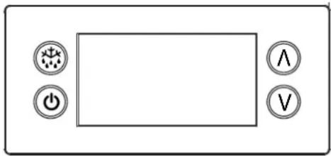
natural_image
Front panel of a device with four labeled buttons (power, battery, switch, and valve) arranged around a blank rectangular area (no text or symbols beyond icons)Control Display
| Operation / Indication | ||
| Status Displayed | Comments | |
| Normal (°C) Temp. [°C] Unit depends on setting | parameters in control | |
| Normal (°F) Temp. [°F] | ||
| Show set-point Temp. | ||
| Set to Defrost dEF / Temp | Depends on setting | |
| Sensor 1 defect E01 | Air sensor | |
| Sensor 2 defect E02 | Coil sensor | |
| High temperature alarm | Hi | Automatically switching at 2 sec rate |
| Low temperature alarm | Lo | |
| Line voltage too high | uHi | |
| Line voltage too low | uLi | |
R290 Temperature Control & Display Operation
Press upper or lower right button.
- Display show actual set-point (blinking).
» If buttons untouched for 3 seconds returns to normal. - Increase set-point by pressing upper button. Max value depends on parameters in control.
- Decrease set-point by pressing lower button. Min value depends on parameters in control.
» If buttons untouched for 3 seconds returns to normal and stores new set-point.
Press upper left button for 5 seconds.
- Start defrost.
Press lower left button for 5 seconds.
- Unit goes into stand-by mode.
» The display will read off, then a period. - Press the lower left button again for 5 seconds.
» The display will read on.
» The unit will then start up in the defrost mode, and display will read dEF.
R290 Power Switch
Two and three door units are equipped with a power disconnect switch located behind the louvered end panel. Switch must be in the on position for the unit to operate. If the switch is turned off, then returned to the on position, the unit will enter a defrost cycle and the display will read dEF.
R290 Energy Saver Switch
Select freezers are equipped with an energy saver switch for service use. It is located in the electrical box behind the front shroud. It controls the length of time that heat is applied to the door perimeter. The normal operating position for this switch is the on position, providing the shortest amount of time. If excessive condensation is observed on the door opening, switch to the off position with the help of an authorized service agent. The off position will increase the length of time the door heater is on.
R290 Temperature Alarm
The alarm will flash "HI" or "LO" 90 minutes after the unit has reached its alarm temperature point or after any power interruption if the temperature is above or below the alarm set points. Refrigerators are factory set at mid-range to maintain about 38^ (3°C) box temperature. The high refrigerator temperature point is 50^ (10°C). The low refrigerator temperature point is 25^ (-4°C). Freezers are factory set at mid-range to maintain about -2^ (-19°C) box temperature. The high freezer temperature point is 20^ (-7°C). Freezers do not have a low temperature point.
R290 EVAPORATOR FAN OPERATION
During normal operation the evaporator fan may cycle and/or pulse independently of the compressor. Consult Technical Support at 1-844-724-CARE if you are unsure of the proper function.
| Cooling Cycle Defrost Cycle | ||||||
| Compressor On | Compressor Off | Compressor Off | ||||
| Evap Fan On | Evap Fan Off | Evap Fan On | Evap Fan Off | Evap Fan On | Evap Fan Off | |
| Refrigerator X Cycles | On 2-Min,Off 2-Min | X | ||||
| Freezer X X | X | |||||
R290 CHANGING DISPLAY FROM FAHRENHEIT TO CELSIUS ON ERC112 CONTROL
- Simultaneously hold the up and down arrows for 5 seconds to access menu for password protected parameters.

text_image
6.01°F- Screen should temporarily flash PAS and then move to a numeric screen.
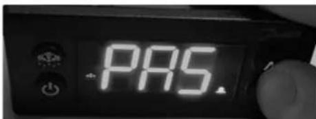
text_image
PAS.- Scroll to 187 using the up/down arrows and push the stand-by button (lower left button) to enter.

text_image
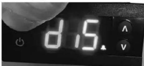
187 V- Scroll to dis using the up/down arrows and push the stand-by button (lower left button) to enter into the display menu.
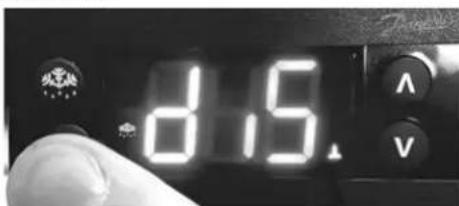
text_image
8.5- Scroll to CFu using the up/down arrows and push the stand-by button (lower left button) to enter the display unit menu.
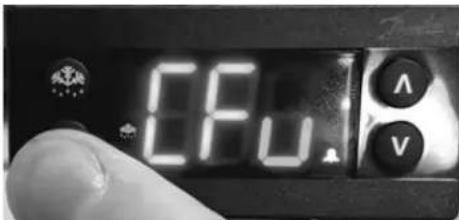
text_image
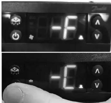
CFU A V- -F should be displayed indicating Fahrenheit. Use the down arrow to change it to -C for Celsius and hit the stand-by button (lower left button) to enter the change.
text_image
-10.0 -1.0- Push the defrost button (upper left button) to move out of the display unit menu.
text_image
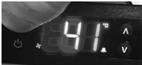
8.15- Push the defrost button (upper left button) to move out of the display menu and back to the normal display. NOTE: For steps 7 and 8, display will return back to normal display after 30 seconds of inactivity.
text_image
81°C A VSection 4
Maintenance
! DANGER
It is the responsibility of the equipment owner to perform a Personal Protective Equipment Hazard Assessment to ensure adequate protection during maintenance procedures.
! DANGER
Failure to disconnect the power at the main power supply disconnect could result in serious injury or death. The power switch DOES NOT disconnect all incoming power.
! DANGER
Disconnect electric power at the main power disconnect for all equipment being serviced. Observe correct polarity of incoming line voltage. Incorrect polarity can lead to erratic operation.
▲Warning
Never use sharp objects or tools to remove ice or frost. Do not use mechanical devices or other means to accelerate the defrosting process.
Cleaning and Sanitizing Procedures
Caution
Maintenance and servicing work other than cleaning as described in this manual must be done by an authorized service personnel.
GENERAL
▲Warning
When using cleaning fluids or chemicals, rubber gloves and eye protection (and/or face shield) must be worn.
You are responsible for maintaining the equipment in accordance with the instructions in this manual. Maintenance procedures are not covered by the warranty.
| Maintenance Daily Weekly Monthly | After Prolonged Shutdown | At Start-Up | ||
| Interior X X X | ||||
| Gasket X X X | ||||
| Exterior X X X | ||||
| Drain X X X | ||||
| Condenser Coil X X X | ||||
| Casters | X X X |
INTERIOR CLEANING
Notice
When cleaning interior and exterior of unit, care should be taken to avoid the front power switch and the rear power cord. Keep water and/or cleaning solutions away from these parts.
Notice
Never use a high-pressure water jet for cleaning or hose down or flood interior or exterior of units with water. Do not use power cleaning equipment, steel wool, scrapers or wire brushes on stainless steel or painted surfaces.
The interior can be cleaned using soap and warm water. If this isn't sufficient, try ammonia and water or a nonabrasive liquid cleaner.
EXTERIOR CLEANING
Notice
Never use an acid based cleaning solution on exterior panels! Many food products have an acidic content, which can deteriorate the finish. Be sure to clean the stainless steel surfaces of ALL food products.
Clean the area around the unit as often as necessary to maintain cleanliness and efficient operation.
Wipe gasket and surfaces with a damp cloth rinsed in water to remove dust and dirt from the outside of the unit. Always rub with the "grain" of the stainless steel to avoid marring the finish. If a greasy residue persists, use a damp cloth rinsed in a mild dish soap and water solution. Wipe dry with a clean, soft cloth.
Never use steel wool or abrasive pads for cleaning. Never use chlorinated, citrus based or abrasive cleaners.
Stainless steel exterior panels have a clear coating that is stain resistant and easy to clean. Products containing abrasives will damage the coating and scratch the panels. Daily cleaning may be followed by an application of stainless steel cleaner which will eliminate water spotting and fingerprints. Early signs of stainless steel breakdown are small pits and cracks. If this has begun, clean thoroughly and start to apply stainless steel cleaners in attempt to restore the steel.
DRAIN
Each unit has a drain located inside the unit that removes the condensation from the evaporator coil and routes it to an external condensate evaporator pan. Each drain can become loose or disconnected during normal use. If you notice water accumulation on the inside of the unit, be sure the drain tube is connected to the evaporator drain pan. If water is collecting underneath the unit, make sure the end of the drain tube is in the condensate evaporator. The leveling of the unit is important as the units are designed to drain properly when level. Be sure all drain lines are free of obstructions.
CLEANING THE CONDENSER COIL
In order to maintain proper refrigeration performance, the condenser fins must be cleaned of dust, dirt and grease regularly. It is recommended that this be done monthly. If conditions are such that the condenser is totally blocked in a month, the frequency of cleaning should be increased. Clean the condenser with a vacuum cleaner or stiff brush. If extremely dirty, a commercially available condenser cleaner may be required.
Failure to maintain a clean condenser coil can initially cause high temperatures and excessive run times. Continuous operation with a dirty or clogged condenser coil can result in compressor failure. Neglecting the condenser coil cleaning procedures will void any warranties associated with the compressor and cost to replace the compressor.
CASTERS
Wipe casters with a damp cloth monthly to prevent corrosion.
DOORS/HINGES
Over time and with heavy-use doors, the hinges may become loose. If this happens, tighten the screws that mount the hinge brackets to the frame of the unit. Loose or sagging doors can cause the hinges to pull out of the frame, which may damage both the doors and the hinges. In some cases this may require qualified service agents or maintenance personnel to perform repairs.
PREVENTING BLOWER COIL CORROSION
To help prevent corrosion of the blower coil, store all acidic items, such as pickles and tomatoes, in seal-able containers. Immediately wipe up all spills.
THIS PAGE INTENTIONALLY LEFT BLANK
Section 5
Troubleshooting
Problem -> Cause -> Correction Chart
| Problem Cause Correction | ||
| Cabinet not running Fuse blown or circuit breaker tripped. Replace fuse of reset circuit breaker. | ||
| Condensing unit runs for long periods or continuously | Excessive amount of warm product placed in cabinet. | Allow adequate time for product to cool down. |
| Prolonged door openings or door(s) ajar. Make sure door(s) are closed when not in use. Avoid prolonged door openings. | ||
| Door gasket(s) not sealing properly. Check gasket condition. Adjust door or replace gasket if necessary. | ||
| Dirty condenser coil. Clean the condenser coil. | ||
| Evaporator coil iced over. Turn unit off and allow coil to defrost.Make sure thermostat is not set too cold.Also, check gasket condition. | ||
| Cabinet temperature is too high | Thermostat set too high. Set thermostat to lower temperature. | |
| Poor air circulation in cabinet. Re-arrange product to allow proper air circulation. | ||
| Exterior thermometer is out of calibration. | Re-calibrate thermometer. | |
| Excessive amount of warm product placed in cabinet. | Allow adequate time for product to cool down. | |
| Prolonged door openings or door(s) ajar. | Make sure door(s) are closed when not in use.Avoid prolonged door openings. | |
| Dirty condenser coil. Clean the condenser coil. | ||
| Evaporator coil iced over. Turn unit off and allow coil to defrost.Make sure thermostat is not set too cold.Also, check gasket condition. | ||
| Cabinet is noisy | Loose part(s). | Locate and tighten loose part(s). |
| Refrigerator is freezing product | Thermostat is set too low. | Set thermostat to higher temperature. |
| Dirty condenser coil. Clean the condenser coil. | ||
| Not enough cabinet clearance for proper refrigeration system operation. | Move cabinet or make other adjustments to gain proper cabinet clearances. | |
| Compressor will not start | Low voltage to cabinet. | Check and correct incoming voltage to cabinet. |
| Temperature display reads E1 | Box temperature sensor circuit is either open or shorted. | Check resistance of sensor for open or short and replace sensor if either condition is found. If not, replace control. |
| Temperature display reads E2 | Coil temperature sensor circuit is either open or shorted. | Check resistance of sensor for open or short and replace sensor if either condition is found. If not, replace control. |
| Temperature display reads E6 | Control has a defective potentiometer. | Replace control. |
| Temperature display reads E13 | Communication error between controller and display. | Check for loose plugs on cable from control to display. If there are no loose plugs the display or control may need to be replaced. |
Every new piece of Welbilt equipment comes with KitchenCare® and you choose the level of service that meets your operational needs from one restaurant to multiple locations.
StarCare – Warranty & lifetime service, certified OEM parts, global parts inventory, performance audited
ExtraCare — CareCode, 24/7 Support, online/mobile product information
LifeCare – Install & equipment orientation, planned maintenance, KitchenConnect™, MenuConnect®
Talk with KitchenCare* • 1-844-724-CARE • www.mtwkitchencare.com
To learn how Welbilt and its leading brands can equip you, visit our global web site at www.welbilt.com, then discover the regional or local resources available to you.

WELBILT®