PDU30SWHVT19ATNET - Inverter CyberPower - Free user manual and instructions
Find the device manual for free PDU30SWHVT19ATNET CyberPower in PDF.

User questions about PDU30SWHVT19ATNET CyberPower
0 question about this device. Answer the ones you know or ask your own.
Ask a new question about this device
Download the instructions for your Inverter in PDF format for free! Find your manual PDU30SWHVT19ATNET - CyberPower and take your electronic device back in hand. On this page are published all the documents necessary for the use of your device. PDU30SWHVT19ATNET by CyberPower.
USER MANUAL PDU30SWHVT19ATNET CyberPower
Automatic Transfer Switch
USER'S MANUAL
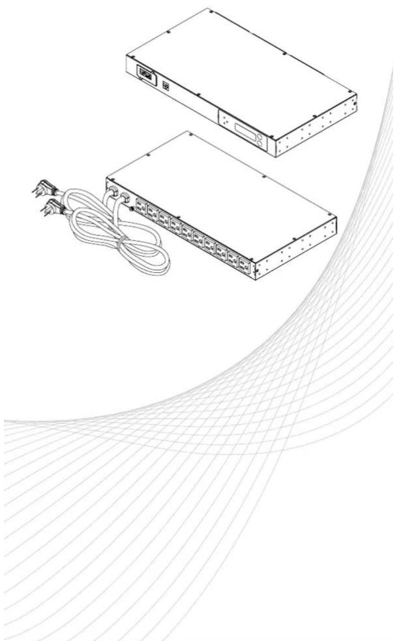
natural_image
Technical line drawing of two electronic devices with cables and connectors, no text or symbols presentTable of Contents
Overview....1
Model List....1
Product Contents 2
For 1U Models....2
For 2U Models....3
Product Features....4
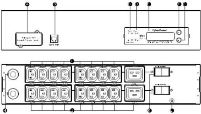
Front/Rear Panel Description (1U 15A Models)....4
Technical Specifications....4
Front/Rear Panel Description (1U 20A Models) ....5
Technical Specifications....5
Front/Rear Panel Description (2U 30A Models)....6
Technical Specifications....6
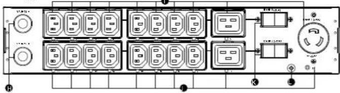
Front/Rear Panel Description (2U 32A Models)....7
Technical Specifications....7
Installation Guide 8
ATS PDU Configuration....8
Front Mounting....9
For 1U Models....9
For 2U Models ....10
Rear Mounting....11
For 1U Models....11
For 2U Models....13
Replacing LCD Panel 15
Electrical Installation 15
Power Cord Locking - For IEC Type ATS PDU 16
Input Power Cord....16
Output Power Cord....16
Network Installation....17
Operation....18
Remote Management....18
Web 18
Telnet and SSH....18
SNMP 18
Local Management....18
LCD Operation....18
LED Indicators....19
Environmental Monitoring (optional)....19
Device Reset 19
Unattended/Automatic Shutdown....19
Firmware Upgrade....20
ATS PDU 20
LCD 21
RMCARD 23
Troubleshooting 25
Conformance Approvals....26
Customer Service & Warranty 27
Appendix A-Hyper Terminal 28
Appendix B-Power Device Network Utility 29
Overview
CyberPower Automatic Transfer Switches PDUs with dual input for power provide redundant and increased reliability for critical devices with a single power plug. Users can define the preferred input power source. When a selected source is unstable or unavailable, the ATS PDU will switch to the second power source to constantly provide power to connected devices. The entire ATS PDU series are designed with LED and LCD interfaces for users to easily observe power status and device load. On-site power management is accomplished as users can configure power settings, via LCD interface, according to local power condition. Available in both switched and metered/monitored configurations, users have a broad base of options to select the ATS PDU that best fits their needs.
WARNING: This automatic transfer switch has dual power cords (A & B) to provide redundant power sources to devices with single power supplies and can be plugged into separate compatible sources* to ensure continuous access. Users select the preferred source as the primary input. CyberPower Smart App Online and Sinewave series UPS are highly recommended for use as the power source.
*Note: Only sine wave AC power sources are compatible with this ATS PDU. Simulated sine wave AC power sources are NOT compatible.
Model List
| Switched Series Metered/Monitored Series | |
| 1U 1U | |
| PDU15SW10ATNET PDU15M10AT | |
| PDU20SW10ATNET PDU20M10AT | |
| PDU20SWT10ATNET PDU20MT10AT | |
| PDU20SWHVT10ATNET PDU20MHVT10AT | |
| PDU15SWHVIEC12ATNET PDU15MHVIEC12AT | |
| PDU20SWHVIEC10ATNET PDU20MHVIEC10AT | |
| PDU20SWHVCEE10ATNET* PDU20MHVCEE10AT* | |
| 2U 2U | |
| PDU30SWT17ATNET PDU30MT17AT | |
| PDU30SWHVT19ATNET PDU30MHVT19AT | |
| PDU32SWHVCEE18ATNET* PDU32MHVCEE18AT* | |
*Selected models may not be available in certain regions. Please contact your CyberPower sales team for more information.
Safety Precautions
Read the following before installing or operating the Automatic Transfer Switches (ATS) PDU:
• Use only the supplied hardware to attach the mounting brackets.
- The ATS PDU must be plugged into a single phase three-wire, grounded outlet on a circuit that is protected by a fuse or circuit breaker. For PDU15xxxx series, please use a 15A circuit protector. For PDU20xxxx series, please use a 20A circuit protector. For PDU30xxxx series, please use a 30A circuit protector. Connection to any other type of power outlet may result in a electrocution hazard.
- Do not use extension cords or adapters with these ATS PDUs.
- Never install an ATS PDU or associated wiring or equipment during a lightning storm.
• Ensure that the power cord, plug, and socket are in good condition.

To prevent the risk of fire or electrocution, this ATS PDU should be installed in a temperature and humidity controlled indoor area free of conductive contaminants. Do not install this ATS PDU where excessive moisture or heat is present.

Before using, please check to ensure the package contains all the items shown below. If there are missing parts, please contact your local CyberPower sales team for technical support.
Product Contents
For 1U Models

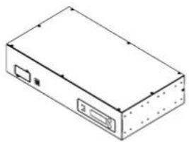
natural_image
Isometric line drawing of a rectangular electronic device with ports and connectors (no text or symbols)ATS PDU


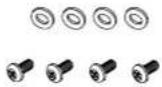
Mounting Bracket x 2 24 (M4x8) Bracket Mounting Screws (Includes eight spares)

natural_image
Technical line drawing of a mechanical support structure (no text or symbols)Cord Retention Tray

4 (M3x4) Cord Retention Tray Mounting Screws

6 (M5x12) Rack Mounting Screws/6 Washers (Includes two spares for each)

Cable Ties
Qty.: 18 (NEMA Outlet)
Qty.: 30 (IEC Outlet)
RJ45/DB9 Serial Port Connection Cable

Jumper (Switched type only)

User's Manual, Registration & Software Download Cards
Below items only provided with IEC type ATS PDU
Power Cord 10 feet
IEC-320 C13/C14 x 2
(PDU15SWHVIEC12ATNET/
PDU15MHVIEC12AT Model Only)
Power Cord 10 feet
IEC-320 C19/C20 x 2
(PDU20SWHVIEC10ATNET/
PDU20MHVIEC10AT Model Only)
Product Contents
For 2U Models
natural_image
Isometric line drawing of a rectangular electronic device with ports and an internal slot (no text or symbols)ATS PDU


Mounting Bracket x 2 24 (M4x8) Bracket Mounting Screws (Includes eight spares)

natural_image
Technical line drawing of two parallel cable or connector bands with mounting brackets (no text or symbols)
Cord Retention Tray X 2 8 (M3x4) Cord Retention Tray Mounting Screws

6 (M5x12) Rack Mounting Screws/6 Washers (Includes two spares for each)
Cable Ties Qty.: 30 (NEMA Outlet) Qty.: 50 (IEC Outlet)


RJ45/DB9 Serial Port Connection Cable
Jumper (Switched type only)

text_image
3.4 Raj-Indian Card Faser Panel Management SoftwareUser's Manual, Registration & Software Download Cards
Product Features
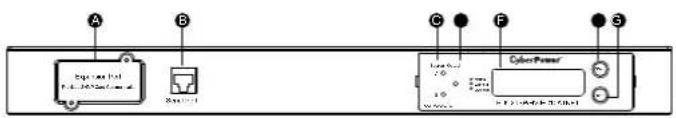
Front/Rear Panel Description (1U 15A Models)
text_image
A B C F S Control PowerNEMA Type
text_image
Diagram of a multi-chamber electrical control panel with labeled terminals and switchesIEC Type
text_image
Diagram of a rack-mounted device with labeled ports and connectors, showing internal structure and pin layout.A. SNMP/HTTP Network Slot
Allows users to remotely control and monitor the ATS PDU when installed with CyberPower's Remote Management Card.
B. Serial Port (RJ45 modular port)
Use serial port to connect with PC and execute local control of the ATS PDU.
C. Source Indicator
Indicates Source A or B is in use. When both sources are normal, selected source shows constant green LED while another source shows blinking green LED.
D. Output Indicator
Indicates load condition of the ATS PDU.
E. Multifunction LCD Readout
Displays various ATS PDU information such as power and load conditions.
F. Select Button
Use to control the LCD screen and toggle through the available informational options.
G. Enter Button
Use to choose selected items, enter to next level menu or return to previous menu.
H. AC Inlet/AC Power Cord
Use to connect ATS PDU to utility power or UPS.
I. Ground Stud
Use to ground the ATS PDU.
J. AC Output Receptacles
Provides power distribution for connected equipment.
K. Outlet Indicator (switched series only)
When the LED is on, the outlet is providing power to connected equipment.
Technical Specifications
| Switched Series Metered Series | ||||
| Model Name PDUISSW10ATNET PDUISSWHMEC2ATNET PDUIISM10AT PDUIISMHWIEC12AT | ||||
| Input | ||||
| Nominal Voltage 100-120V | 200-240V 100-120V | 200-240V | ||
| Frequency 50/60Hz | ||||
| Derated Input Current 12A | 2A(UL)/10A(CE) 12A 12A(UL)/10A(CE) | |||
| Plug Type | (2) NEMA 5-15P | (2) IEC-320 C14 | (2) NEMA 5-15P | (2) IEC-320 C14 |
| Power Cord Type SR (14 AWG) Socket SR (14 AWG) Socket | ||||
| Power Cord Length | 10 ft/3.05 m | |||
| Output | ||||
| Nominal Voltage 100-120V | 200-240V 100-120V | 200-240V | ||
| Derated Output Current | 12A 12A(UL)/10A(CE) 12A 12A(UL)/10A(CE) | |||
| Outlet Type | NEMA 5-15R | IEC-320 C13 | NEMA 5-15R | IEC-320 C13 |
| Outlet Number | 10 | 12 | 10 | 12 |
| Transfer Time | Typical: 8-12ms16ms max @ 60Hz/ 18ms max @ 50Hz | |||
| Management and Communications | ||||
| Multifunction LCD Roadout | Voltage, Frequency, Load, Current, ITW/FW Version, Network Information | |||
| Software | PowerPane? Business Edition | |||
| SNMP/ HTTP Capable | Yes, with RMCARD | Yes, with optional RMCARD | ||
| Connectivity | RJ45 (Serial Port) | |||
| Sensor Capable | Optional | |||
| Physical | ||||
| Dimension (W x H x D) | 17.05" x 1.75" x 9.3"/433mm x 44mm x 236mm | |||
| Environmental | ||||
| Humidity | 0 to 95% Non-condensing | |||
| Altitude | 13100 ft/4000 m | |||
| Temperature | 32°F to 113°F/0°C to 15°C | |||
| Safety Approvals | ||||
| Certifications | UL 60950 1FCC Class A | UL 60950 1CE, FCC Class A | UL 60950 1FCC Class A | UL 60950 1CE, FCC Class A |
* All specifications are subject to change without notice.
Product Features
Front/Rear Panel Description (1U 20A Models)

text_image
A B C D E F S CyanPowerNEMA Type
text_image
Diagram of a rack-mounted network device with labeled ports and connectorsIEC Type

text_image
Diagram of a rack-mounted server or network interface with multiple switches and ports, labeled with connection points and status indicators.A. SNMP/HTTP Network Slot
Allows users to remotely control and monitor the ATS PDU when installed with CyberPower's Remote Management Card.
B. Serial Port (RJ45 modular port)
Use serial port to connect with PC and execute local control of the ATS PDU.
C. Source Indicator
Indicates Source A or B is in use. When both sources are normal, selected source shows constant green LED while another source shows blinking green LED.
D. Output Indicator
Indicates load condition of the ATS PDU.
E. Multifunction LCD Readout
Displays various ATS PDU information such as power and load conditions.
F. Select Button
Use to control the LCD screen and toggle through the available informational options.
G. Enter Button
Use to choose selected items, enter to next level menu or return to previous menu.
H. AC Inlet/AC Power Cord
Use to connect ATS PDU to utility power or UPS.
I. Ground Stud
Use to ground the ATS PDU.
J. AC Output Receptacles
Provides power distribution for connected equipment.
K. Outlet Indicator (switched series only)
When the LED is on, the outlet is providing power to connected equipment.
Technical Specifications
| Switched Series Metered Series | ||||
| Model Name | PDU20SW10ATNET | PDU20SWHVT10ATNET | PDU20V10AT | PDU20MHVT10AT |
| PDU20SWHVCEE10ATNET | PDU20MHVCEE10AT | |||
| PDU20SWT10ATNET | S-10000A | S-10000A | S-10000A | |
| S-20000VA/MEC10ATNET | S-2000MHVEC10AT | |||
| Input | ||||
| Nominal Voltage 100-120V | 200-240V 100-120V | 200-240V | ||
| Frequency 50/60Hz | ||||
| Derated Input Current 16A | ||||
| Plug Type | (2) NEMA 5 20P | (2) NEMA L6-20P | (2) NEMA 5-20P | (2) NEMA L6-20P |
| (2) IEC 309 16A | (2) IEC 309 16A | |||
| (2) NEMA L5-20P | (2) IEC 320 C20 | (2) NEMA L5 20P | (2) IEC 320 C20 | |
| Power Cord Type | SR (12AWG) | SR (12AWG) | SR (12 AWG) | SR (12AWG) |
| Socket | Socket | |||
| Power Cord Length | 10 ft/3.05 m | |||
| Output | ||||
| Nominal Voltage 100-120V | 200-240V 100-120V | 200-240V | ||
| Derated Output Current | 16A | C'3:12A (UL)10A (CE)C'9:16A | 16A | C13:12A (UL)10A (CE)C19:16A |
| Outlet Type | NEMA 5-20R | (8) ILC C13(2) ILC C19 | NEMA 5-20R | (8) ILC C13(2) ILC C19 |
| Outlet Number | 10 | 8+2 | 10 | 8+2 |
| Transfer Time | Typical: 8-12ms16ms max @ 60Hz/18ms max @ 50Hz | |||
| Management and Communications | ||||
| Multifunction LCD Readout | Voltage, Frequency, Load, Current: HW/FW Version, Network Information | |||
| Software PowerPanel® Business Edition | ||||
| SNMP/ HTTP Capable | Yes, with RMCARD | Yes, with optional RMCARD | ||
| Connectivity | RJ45 (Serial Port) | |||
| Sensor Capable | Optional | |||
| Physical | ||||
| Dimension (W x H x D) | 17.05" x 1.75" x 9.3"/433mm x 44mm x 236mm | |||
| Environmental | ||||
| Humidity | 0 to 95% Non-condensing | |||
| Altitude | 13100 ft/4000 m | |||
| Temporaure | 32°F to 13°F/0°C to 45°C | |||
| Safety Approvals | ||||
| Certifications | UL 60950-1FCC Class A | UL 60950-1FCC Class A | UL 60950-1FCC Class A | UL 60950-1FCC Class A |
| UL 60950-1CL, FCC Class A | UL 60950-1CL, FCC Class A | |||
* All specifications are subject to change without notice.
Product Features
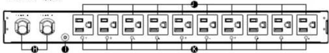
Front/Rear Panel Description (2U 30A Models)

text_image
A B C E F G Equistar Power CyberPowerNEMA Type

flowchart
graph LR
    A["Input Unit 1"] --> B["Switch 1"]
    C["Input Unit 2"] --> D["Switch 2"]
    E["Input Unit 3"] --> F["Switch 3"]
    G["Input Unit 4"] --> H["Switch 4"]
    I["Input Unit 5"] --> J["Switch 5"]
    K["Input Unit 6"] --> L["Switch 6"]
    M["Input Unit 7"] --> N["Switch 7"]
    O["Input Unit 8"] --> P["Switch 8"]
    Q["Input Unit 9"] --> R["Switch 9"]
    S["Input Unit 10"] --> T["Switch 10"]
    U["Output Unit 1"] --> V["Switch 1"]
    W["Output Unit 2"] --> X["Switch 2"]
    Y["Output Unit 3"] --> Z["Switch 3"]
    AA["Output Unit 4"] --> AB["Switch 4"]
    AC["Output Unit 5"] --> AD["Switch 5"]
    AE["Output Unit 6"] --> AF["Switch 6"]
    AG["Output Unit 7"] --> AH["Switch 7"]
    AI["Output Unit 8"] --> AJ["Switch 8"]
    AK["Output Unit 9"] --> AL["Switch 9"]
    AM["Output Unit 10"] --> AN["Switch 10"]
IEC Type
text_image
Electrical panel diagram with labeled components including switches, relays, and power connectionsA. SNMP/HTTP Network Slot Allows users to remotely control and monitor the ATS PDU when installed with CyberPower's Remote Management Card.
B. Serial Port (RJ45 modular port) Use serial port to connect with PC and execute local control of the ATS PDU.
C. Source Indicator Indicates Source A or B is in use. When both sources are normal, selected source shows constant green LED while another source shows blinking green LED.
D. Output Indicator Indicates load condition of the ATS PDU.
E. Multifunction LCD Readout Displays various ATS PDU information such as power and load conditions.
F. Select Button Use to control the LCD screen and toggle through the available informational options.
G. Enter Button Use to choose selected items, enter to next level menu or return to previous menu.
H. AC Inlet/AC Power Cord Use to connect ATS PDU to utility power or UPS.
I. AC Output Receptacles Provides power distribution for connected equipment.
J. Outlet Indicator (switched series only) When the LED is on, the outlet is providing power to connected equipment.
K. Circuit Breaker Provides output overload protection.
L. Ground Stud Use to ground the ATS PDU.
Technical Specifications
| Switched Series | Metered Series | |||
| Model Name | PDU30SWT17ATNET | PDU30SWHVT 9ATNET | PDU30MT17AT | PDU30MHVT 9AT |
| Input | ||||
| Nominal Voltage | 100-120V | 200-240V | 100-120V | 200-240V |
| Frequency | 50/60Hz | |||
| Derated Input Current | 2/A | |||
| Plug Type | (2) NEMA L5 30P | (2) NEMA L5 30P | (2) NEMA L5 30P | (2) NEMA L6 30P |
| Power Cord Type | SR (10 AWG) | |||
| Power Cord Length | 10 f/(3.05 m | |||
| Output | ||||
| Nominal Voltage | 100-120V | 200-240V | 100-120V | 200-240V |
| Derated Output Current | 5-20R: 16AL5-30R: 24A | C13: 12AC19: 16AL6-30R: 24A | 5-20R: 16AL5-30R: 24A | C13: 12AC19: 16AL6-30R: 24A |
| Derated Output Current (each bank) | 20A | |||
| Bank Number | 2 | |||
| Outlet Type | (16) NFMA 5-20R(1) NEMA L5-30R | (16) IFC C13(2) IFC C19(1) NEMA L6-30R | (16) NFMA 5-20R(1) NEMA L5-30R | (16) IFC C13(2) IFC C19(1) NFMA L6-30R |
| Outlet Number | 17 | 19 | 17 | 19 |
| Circuit Breaker | Yes | |||
| Transfer Time | Typical: 8-12ms16ms max @ 60Hz/ 18ms max @ 50Hz | |||
| Management and Communications | ||||
| Multi-function LCD Readout | Voltage, Frequency, Load, Current, HW/FW Version, Network Information | |||
| Software | PowerPanel® Business Edition | |||
| SNMP/ HTTP Capable | Yes, with RMCARD | Yes, with optional RMCARD | ||
| Connectivity | RJ45 (Serial Port) | |||
| Sensor Capable | Optional | |||
| Physical | ||||
| Dimension (W x H x D) | 17.05" x 3.5" x 9.3"/433mm x 88mm x 236mm | |||
| Environmental | ||||
| Humidity | 0 to 95% Non-condensing | |||
| Altitude | 13100 ft/4000 m | |||
| Temperature | 32°F to 13.1/0°C to 45°C | |||
| Safety Approvals | ||||
| Certifications | UL 60950-1, FCC Class A | |||
* All specifications are subject to change without notice.
Product Features
Front/Rear Panel Description (2U 32A Models)
text_image
A B C D E F G H I J K L P1-120V P1-120V P1-120V P1-120V P1-120V P1-120V P1-120V P1-120V P1-120V P1-120V P1-120V P1-120V P1-120V P1 120V P1 120V P1 120V P1 120V P1 120V P1 120V P1 120V P1 120V P1 120V P1 120V P1 120V P1 120V P1 120 V P1 120 V P1 120 V P1 120 V P1 120 V P1 120 V P1 120 V P1 120 V P1 120 V P1 120 V P1 120 V P1 120 V P1 120 V P1.53V P1.53V P1.53V P1.53V P1.53V P1.53V P1.53V P1.53V P1.53V P1.53V P1.53V P1.53V P1.53V P1.53V P1.53V SA. SNMP/HTTP Network Slot
Allows users to remotely control and monitor the ATS PDU when installed with CyberPower's Remote Management Card.
B. Serial Port (RJ45 modular port)
Use serial port to connect with PC and execute local control of the ATS PDU.
C. Source Indicator
Indicates Source A or B is in use. When both sources are normal, selected source shows constant green LED while another source shows blinking green LED.
D. Output Indicator
Indicates load condition of the ATS PDU.
E. Multifunction LCD Readout
Displays various ATS PDU information such as power and load conditions.
F. Select Button
Use to control the LCD screen and toggle through the available informational options.
G. Enter Button
Use to choose selected items, enter to next level menu or return to previous menu.
H. AC Inlet/AC Power Cord
Use to connect ATS PDU to utility power or UPS.
I. AC Output Receptacles
Provides power distribution for connected equipment.
J. Outlet Indicator (switched series only)
When the LED is on, the outlet is providing power to connected equipment.
K. Circuit Breaker
Provides output overload protection.
L. Ground Stud
Use to ground the ATS PDU.
Technical Specifications
| Switched Series Metered Series | ||
| Model Name PDU32SWHVCEE | E'BATNET PDU32MHVCEEIBAT | |
| Input | ||
| Nominal Voltage 200-240V | ||
| Frequency 50/60Hz | ||
| Max. Input Current 32A | ||
| Plug Type (2) IEC 309 32A | ||
| Power Cord Type SR (10 AWG) | ||
| Power Cord Length 10 fL/3.05 m | ||
| Output | ||
| Nominal Voltage 200-240V | ||
| Dorated Output Current | C13: 10AC19: 16A | |
| Dorated Output Current (each bank) | 20A | |
| Bank Number 2 | ||
| Outlet Type | (16) IEC C13(7) IEC C19 | |
| Outlet Number 18 | ||
| Circuit Breaker Yes | ||
| Transfer Time | Typical: 8-12ms16ms max @ 60Hz/ 16ms max @ 50Hz | |
| Management and Communications | ||
| Mult function LCD Readout | Voltage, Frequency Load, Current, HW/FW Version, Network Information | |
| Software | PowerPanel Business Edition | |
| SNMP/ HTTP Capable | Yes, with RMCARD | Yes, with optionalRMCARD |
| Connectivity | RJ45 (Serial Port) | |
| Sensor Capable | Optional | |
| Physical | ||
| Dimension (W x H x D) | 17.05" x 3.5" x 9.3"/433min x 88mm x 236mm | |
| Environmental | ||
| Humidity | 0 to 95% Non-condensing | |
| Altitude 15'00 ft/4000 m | ||
| Temperature 32 | °F to 13°F/0°C to 45°C | |
| Safety Approvals | ||
| Certifications | CE, FCC Class A | |
* All specifications are subject to change without notice.
Installation Guide
ATS PDU Configuration
WARNING: This automatic transfer switch has dual power cords (A & B) to provide redundant power sources to devices with single power supplies and can be plugged into separate compatible sources* to ensure continuous access. Users select the preferred source as the primary input. CyberPower Smart App Online and Sinewave series UPS are highly recommended for use as the power source.
*Note: Only sine wave AC power sources are compatible with this ATS PDU. Simulated sine wave AC power sources are NOT compatible.
Best Configuration
flowchart
graph TD
    A["Utility Power Utility Power"] --> B["CyberPower Online UPS"]
    C["CyberPower Online UPS"] --> D["CyberPower ATS PDU"]
    E["SOURCE A SOURCE B"] --> D
    F["Equipment Loads"] --> D
Minimum Acceptable Configuration

text_image
Utility Power CyberPower Sinewave UPS SOURCE A (Preferred Source) SOURCE B CyberPower ATS PDU Equipment LoadsInstallation Guide

Please only use the provided screws for the entire installation process.
Front Mounting
For 1U Models
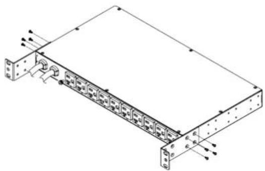
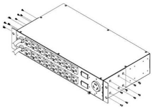
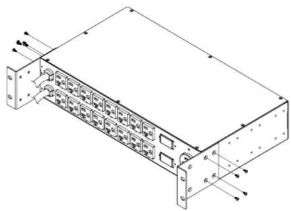
Step 1. Mounting Bracket Installation
Use the provided Mounting Bracket Screws (16) to attach the Mounting Brackets (2) to the ATS PDU.
natural_image
Isometric line drawing of a rectangular electronic device with ports and connectors (no text or symbols)Step 2. Cord Retention Tray Installation (optional)
Adjust the length of the Cord Retention Tray till the screw hole on the Tray and ATS PDU are aligned. Attach the Cord Retention Tray to the ATS PDU with the 4 supplied Cord Retention Tray Mounting Screws. Tighten the Cord Retention Tray with the screw on it.
natural_image
Technical diagram of a server rack with mounting hardware and a close-up inset showing internal components (no text or symbols)Step 3. ATS PDU Mounting
Use the provided Washers (4) and Screws (4) to secure the ATS PDU to your existing rack system.
Note: You may also use the screw sets provided by the rack to secure the ATS PDU.
natural_image
Technical line drawing of a mechanical assembly with mounting brackets and a side view showing internal components (no text or symbols)Installation Guide
Front Mounting
Step 4. Cable Ties (Optional)
Use the provided Cable Ties to fasten each cord to the Cord Retention Tray.

natural_image
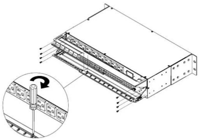
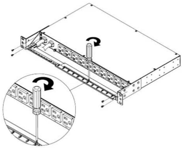
Technical line drawing of a mechanical assembly with mounting brackets and internal components, plus an inset magnified view (no text or symbols)For 2U Models
Step 1. Mounting Bracket Installation
Use the provided Mounting Bracket Screws (16) to attach the Mounting Brackets (2) to the ATS PDU.

natural_image
Technical line drawing of an electronic device casing with ports and connectors (no text or symbols)Step 2. Cord Retention Tray Installation (optional)
Adjust the length of the Cord Retention Trays till the screw hole on the Trays and ATS PDU are aligned. Attach the Cord Retention Trays to the ATS PDU with the 8 supplied Cord Retention Tray Mounting Screws. Tighten the Cord Retention Trays with the screw on it.
natural_image
Technical line drawing of a server rack with an inset showing a screwdriver inserted into a rack (no text or symbols present)Installation Guide
Front Mounting
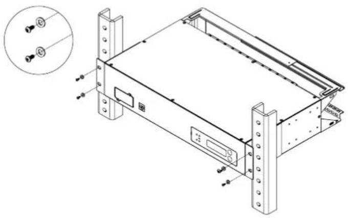
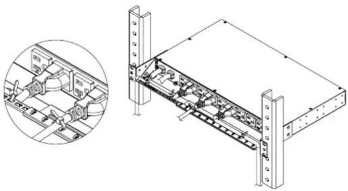
Step 3. ATS PDU Mounting
Use the provided Washers (4) and Screws (4) to secure the ATS PDU to your existing rack system.
Note: You may also use the screw sets provided by the rack to secure the ATS PDU.
natural_image
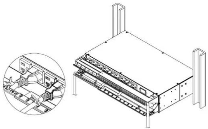
Technical line drawing of a server rack unit with mounting brackets and a close-up inset showing two sensors (no text or symbols present)Step 4. Cable Ties (Optional)
Use the provided Cable Ties to fasten each cord to the Cord Retention Tray.
natural_image
Technical line drawing of a mechanical assembly with an inset close-up showing internal components (no text or symbols)Rear Mounting
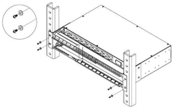
For 1U Models
Step 1. Mounting Bracket Installation
Use the provided Mounting Bracket Screws (16) to attach the Mounting Brackets (2) to the ATS PDU.

natural_image
Isometric line drawing of a server rack with multiple ports and connectors (no text or symbols)Installation Guide
Rear Mounting
If you plan on attaching the Cord Retention Tray to the ATS PDU, use the provided Mounting Bracket Screws (8) to attach the Mounting Brackets (2) to the ATS PDU.
natural_image
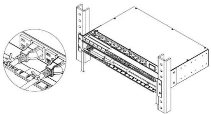
Isometric line drawing of a rack-mounted server or network device with multiple ports and connectors (no text or symbols)Step 2. Cord Retention Tray Installation (optional)
Adjust the length of the Cord Retention Tray till the screw hole on the Tray and ATS PDU are aligned. Attach the Cord Retention Tray to the ATS PDU with the 4 supplied Cord Retention Tray Mounting Screws. Tighten the Cord Retention Tray with the screw on it.
natural_image
Technical line drawing of a server rack with mounting hardware and a close-up inset showing internal components (no text or symbols)Step 3. ATS PDU Mounting
Use the provided Washers (4) and Screws (4) to secure the ATS PDU to your existing rack system.
Note: You may also use the screw sets provided by the rack to secure the ATS PDU.

natural_image
Technical line drawing of a server rack with mounting brackets and a close-up inset showing two screws (no text or symbols present)Installation Guide
Rear Mounting
Step 4. Cable Ties (Optional)
Use the provided Cable Ties to fasten each cord to the Cord Retention Tray.
natural_image
Technical line drawing of a mechanical assembly with a magnified inset showing internal components (no text or symbols)For 2U Models
Step 1. Mounting Bracket Installation
Use the provided Mounting Bracket Screws (16) to attach the Mounting Brackets (2) to the ATS PDU.
natural_image
Technical line drawing of a rack-mounted electronic device with multiple ports and connectors (no text or symbols)If you plan on attaching the Cord Retention Tray to the ATS PDU, use the provided Mounting Bracket Screws (8) to attach the Mounting Brackets (2) to the ATS PDU.
natural_image
Technical line drawing of a rack-mounted server or network device with multiple ports and connectors (no text or symbols visible)Installation Guide
Rear Mounting
Step 2. Cord Retention Tray Installation (optional)
Adjust the length of the Cord Retention Trays till the screw hole on the Trays and ATS PDU are aligned. Attach the Cord Retention Trays to the ATS PDU with the 8 supplied Cord Retention Tray Mounting Screws. Tighten the Cord Retention Trays with the screw on it.

natural_image
Technical line drawing of a server rack with an inset showing a mechanical component being inserted (no text or symbols present)Step 3. ATS PDU Mounting
Use the provided Washers (4) and Screws (4) to secure the ATS PDU to your existing rack system.
Note: You may also use the screw sets provided by the rack to secure the ATS PDU.
natural_image
Technical line drawing of a server rack with mounting brackets and internal panel structure (no text or symbols)Step 4. Cable Ties (Optional)
Use the provided Cable Ties to fasten each cord to the Cord Retention Tray.
natural_image
Technical line drawing of a server rack unit with an inset close-up showing internal components (no text or symbols)Installation Guide
Replacing the LCD Panel
Step 1. Use a slotted screwdriver to gently lift out the LCD panel.
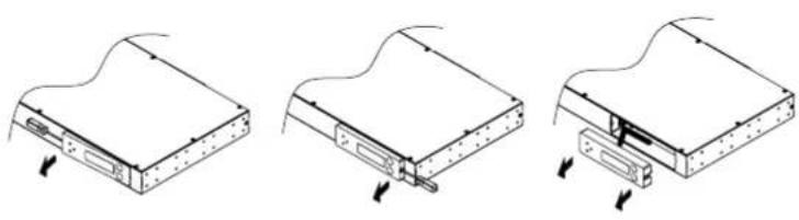
natural_image
Three technical line drawings showing mechanical assembly steps (no text or symbols)Step 2. Disconnect the cable connector.

natural_image
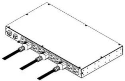
Technical illustration of a mechanical component with an inset showing internal structure and directional arrows (no text or symbols)Electrical Installation
Step 1. Receptacle evaluation
Ensure that the plug type of your ATS PDU unit matches the receptacles that you are using.

The ATS PDU must be plugged into a three-wire, grounded utility receptacle or a UPS that is connected to a grounded utility receptacle. The utility receptacle must also be connected to an appropriate branch circuit/main with fuse or circuit breaker protection. Connection to any other type of receptacle may result in an electrocution hazard.
Step 2. Plug the ATS PDU into the utility receptacle and/or UPS.
For configuration details, refer to ATS PDU Configuration on page 8.
Step 3. Attach equipment
It is extremely important not to exceed the ATS PDU's maximum current load (as outlined in the Specifications section). In order to determine total load, use the LCD screen on the front of the ATS PDU to monitor the load being attached.
natural_image
Isometric line drawing of a rectangular electronic device with multiple ports and connectors (no text or symbols)Installation Guide
Power Cord Locking - For IEC Type ATS PDU
Input Power Cord
Step 1. Align and insert the Cable Tie from the upper side of the Fixed Stand and fasten it as shown below.
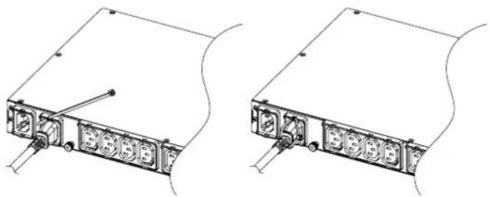
natural_image
Technical line drawing of two electronic device modules with connectors and ports (no text or symbols)Step 2. Align and insert the Cable Tie from the bottom side of the Fixed Stand and fasten it as shown below.
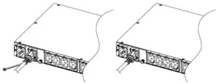
natural_image
Technical line drawing of two electronic device modules with ports and connectors (no text or symbols)Output Power Cord
Step 1. Align and insert the Cable Tie from the upper side of the Fixed Stand and fasten it as shown below.

natural_image
Technical line drawing of two mechanical components with labeled ports and mounting holes (no text or symbols)Installation Guide
Network Installation
(Performed when a Remote Management Card is installed)
Step 1. Attach the LAN Cable
Using a CAT5 RJ45 cable, attach one end to the Ethernet port on the RMCARD, and the other end to a network port.
Step 2. Establish the ATS PDU IP address
Assigning an IP address to the CyberPower ATS PDU requires the user to have an available IP address that is valid on the respective network. If an available IP address is unknown, contact the network administrator to obtain one. The default IP is 192.168.20.177 and the default for the DHCP function is on.
There are multiple methods for setting up the IP address of the ATS PDU
Please follow the instructions below for the method that is appropriate for your application.
Please make sure the ATS PDU is powered on during this process.
Option 1 (recommended): Power Device Network Utility
-
Download the Power Device Network Utility software available at www.cyberpower.com.
-
Highlight the ATS PDU device from the list and select Edit and Setup device => Assisted Setup from the menu.
-
Configure the IP Address, Subnet Mask, and Gateway Address to match your network settings.
-
Enter the user name and password of the ATS PDU device at the Authentication menu.
Note: The default username is "cyber" and the default password is "cyber". For further information and installation instructions, see Appendix B.
Option 2: DHCP Server
-
Ask your administrator if there is DHCP server on the LAN.
-
Make sure the DHCP is Enabled.
-
Make sure the network connection is ready and power on the ATS PDU.
-
The ATS PDU will obtain an IP address from the DHCP server automatically.
Option 3: Address Resolution Protocol (ARP) Command
-
Obtain the MAC address from the sticker on the ATS PDU.
-
Open a command prompt as an administrator and type the following: "arp -s [available IP address] [MAC address of ATS PDU]".
Example: arp -s 192.168.20.240 00-0C-15-00-00-01
IP Address MAC Address
- Use the Ping command to assign a size of 123 bytes to the IP.
* Type in "ping 192.168.20.240 -l 123" then press Enter.
* If the replies are received, your computer can communicate with the IP address.
Option 4: Hyper Terminal or Terminal Emulator
-
Use the included RJ45/DB9 serial port connection cable, attach one end to the serial port on the front of the ATS PDU, and the other end to the PC/server.
-
Open the Hyper Terminal software on your PC and select a name and icon for the connection.
-
Setup the COM port settings using the values indicated in Appendix A.
-
Press Enter to enter the Authentication menu.
-
Enter the user name and password of the ATS PDU device at the Authentication menu.
-
Press 4 and Enter to access Network Settings to view the IP address.
Note: The default username is "cyber" and the default password is "cyber".
For further information and configuration via Hyper Terminal, see Appendix A-Hyper Terminal.
Operation
Remote Management
The remote management function via the RMCARD205 provides for monitoring of the ATS PDU operational information, controlling outlets and utilizing SNMP functionality.
Web
Remote management can be performed via web interface. To access the web interface, please follow the instructions below:
-
Enter the IP address of the ATS PDU into a web browser.
-
Enter the user name and password of the ATS PDU device at the authentication screen.
Note: The default username is "cyber" and the default password is "cyber".
Telnet and SSH
The CyberPower ATS PDU provides Telnet and Secure Shell (SSH) as Remote Management methods. Telnet uses user name and password as basic security while SSH has a higher security level with encryption of the transmitted packets including user name, password, and data. Configure the Setting of Telnet and SSH on the Web Interface. The default user name and password is cyber/cyber.
Note: When user logs in with the admin username and admin password through Telnet or SSH, there are two types of interfaces available. One is the command line interface (CLI) and the other is a menu interface. The default is CLI. If the user wants to change to the menu interface, type in the [menumode] command. To switch back to CLI, it is necessary to logout and login to the RMCARD.
SNMP
The CyberPower ATS PDU supports SNMPv1 and SNMPv3 protocols. Download the CyberPower MIB file and add it to a SNMP-supported management software. Default read/write community is public/private for SNMPv1. SNMPv3 provides a higher security level than SNMPv1 by encrypting the transmitted packet. Configure the settings of the SNMPv1/SNMPv3 on Web Interface. For more details, please see the RMCARD205 User Manual.
Local Management
LCD Operation
The LCD screen provides instant information, such as source condition, voltage and current, for the ATS PDU. In addition, users can use the interface to configure each PDU parameters and control each outlet on the switched ATS PDU.
A. Scroll Mode: The ATS PDU information will display in following order automatically when "Scroll Mode On" is configured.
| Source A information |
| Source B information |
| Device Load |
| Bank 1 Current (2U series) |
| Bank 2 Current (2U series) |
| Bank 3 Current (2U series) |
| Environment Status (Displays when the ENVIROSENSOR is connected) |
B. Main Menu Map
| About | Hardware Version |
| Firmware Version | |
| Network Information | |
| Serial Number |
| Settings | Preferred Source | A/B/None | ||
| Source Configuration | Nominal Voltage | |||
| Voltage Range | ||||
| Freq. Deviation | ||||
| Sensitivity | ||||
| Load Configuration | Device Bank/1/2/3 | Overload Threshold | ||
| Near Overload Threshold | ||||
| Low Load Threshold | ||||
| Outlet Control | Device Bank/1/2/3 | All/Outlet 1-N | Immediate On | |
| Delay On | ||||
| Immediate Off | ||||
| Delay Off | ||||
| Reboot | ||||
| Delay Reboot | ||||
| LCD Settings | Brightness | |||
| Scroll Mode | ||||
| Screen Off |
Operation
Local Management
| Reset/Reboot | Reset All (ATS PDU, RMCARD and LCD) |
| Reset Except TCP/IP | |
| Reset Account (User Name and Password) | |
| Reboot |
LED Indicators
| Indicator | Status Description | on |
| Source | Solid Green S | Selected source and power condition is normal. |
| Flashing Green | Backup source and power condition is normal. | |
| Orange Power condition is abnormal. | ||
| Load | Green The aggregate current of each bank is normal. | |
| Orange Near overload. | ||
| Red Overload. | ||
| Tx/Rx | Off The ATS PDU power is off. | |
| On (Green) The ATS PDU power is on. | ||
| Flashing | Receiving/transmitting data packet. | |
| Reset finished. | ||
| LINK | On Indicates the ATS PDU is connected to the LAN. | |
| Off Indicates the ATS PDU is not connected to the LAN. | ||
| Outlet | On The outlet is on and providing power. | |
| Off The outlet is off. | ||
Environmental Monitoring (optional)
The CyberPower ATS PDU with an environmental sensor (ENVIROSENSOR) installed, provides remote temperature and humidity monitoring in a server closet and/or datacenter. To connect ATS PDU with ENVIROSENSOR, use RJ45 Ethernet Cable included with the ENVIROSENSOR. Plug one end into the Universal port on the RMCARD205 and the other end into the RJ45 port on the ENVIROSENSOR (as shown in figures below). When the ATS PDU connected correctly to the ENVIROSENSOR, users can see the temperature and humidity data via the Web Interface.

text_image
Diagram showing cable connection to a device with an inset close-up highlighting a component detailDevice Reset
- To reset all the settings to default locally, use Reset function in the LCD screen.
- To reset all the settings to default remotely, log in Web interface, enter the Reset page and apply the function.
Unattended/Automatic Shutdown
PowerPanel Business Edition software automatically initiates a graceful shutdown on the connected computer's operating system in an orderly fashion.
PowerPanel must be installed on every computer or server for which the shutdown is to take place. The computer will receive a device status message from the RMCARD205 and will perform the shutdown according to the instructions provided, including shutdowns at exact times and dates. Follow the directions below for setting up Unattended/Automatic Shutdown.
Step 1. Computer Configuration
- Install PowerPanel Business Edition Client on every computer/server that will be part of the shutdown process (Follow the instructions in the PowerPanel Business Edition Client User Manual).
- Configure the settings in PowerPanel Business Edition Client. See the PowerPanel Business Edition Client User Manual for detailed instructions.
Step 2. ATS PDU Network Configuration
Verify that the IP address of all computers, that will be part of the shutdown process, are included in the Client List of the web interface (Follow the instructions in the PowerPanel Business Edition User Manual).
Step 3. Notification
Notifying the computers of potential outlet shutdowns can be accomplished using the following functions:
- Outlets Control Menu: Performing the task of turning off or rebooting outlets
- Scheduling Menu: Setting the application to perform the task of turning off or rebooting outlets. The notification will occur prior to the scheduled date/time.
- Outlet Overload: In the event of ATS PDU overload, notification will be sent prior to the ATS PDU shutting down.
Firmware Upgrade
By upgrading the Firmware, you can obtain new features, updates and improvements to existing functionality. To ensure the firmware is kept up to date, please regularly visit our website to see if there is any updated firmware version available.
Note: Please do not turn the ATS PDU off when processing the firmware upgrade. ATS PDU outlets will remain powered on while the firmware update takes place. Only the ATS PDU LCD screen will reboot.
ATS PDU
Update the following file to upgrade the firmware.
- cpsatsmafw_xxx.bin
Note that the XXX is not part of the file name but is where the version number in the filename is given.
Use the following steps to upgrade the firmware.
-
Download the latest firmware from www.cyberpower.com.
-
Extract the file to "C:\".
-
Open Hyper Terminal to connect the ATS PDU and use the command @NEW".
Note: In order for Hyper Terminal to interact with the ATS PDU, the PC/server must be connected directly to the ATS PDU via the serial port.
(1). Use the included RJ45/DB9 serial port connection cable. Attach one end to the serial port on the front of the ATS PDU, and the other end to the PC/server.
(2). Open the Hyper Terminal software on your PC and select a name and icon for the connection.
(3). Setup the COM port settings using the following values.
* Bits per second: 38400
* Data bits: 8
* Parity: None
* Stop bits: 1
* Flow control: None
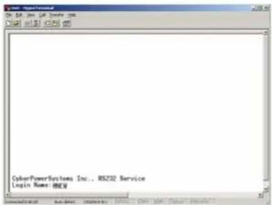
text_image
CyberPowerSystems Inc., RS232 Service Login Name: HKEY- The ATS PDU will reboot and show main menu on Hyper Terminal.
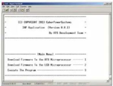
text_image
C) COPYRIGHT 2013 CyberPowerSystems IMP Application (Version 0.8.1) By AIS Development Team [Main Menu] Download Firmware to the AIS Microprocessor Download Firmware to the LCD Microprocessor Execute The Program Downloaded: 1 Downloaded: 2 3- Press "1" to select ATS PDU upgrade.

text_image
IMP Application (Version 0.0.1) By RTS Development Team ------------------------ --------------------- INMain Manual ------------------ Download Firmware to the RTS Microprocessor ----------------------- 1 Download Firmware to the LCD Microprocessor ------------------------- 2 Execute The Program ------------------------- 3 ----------------------- 1 Waiting for the file to be sent ... {press 'a' to abort} CDDCCCCCCCCC_Firmware Upgrade
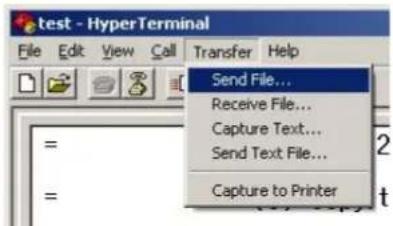
- Select Transfer > Send File.
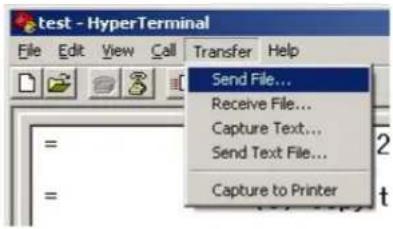
text_image
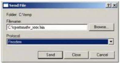
test - HyperTerminal File Edit View Call Transfer Help Send File... Receive File... Capture Text... Send Text File... Capture to Printer- Note that the Ymodem protocol and file "C:\cpsatsmafw_xxx.bin" are selected in Hyper Terminal.
text_image
Send File Folder: C:\temp Filename: C:\cpstatmsfw_yoc.ha Browse... Protocol: Ymodem Send Close Cancel- The download progress window will open after you click the Send button.

text_image
Newcom file send for test Sending C:\inputsafe_xoo.his Packet 0 Error checking ORC File size OK Return 3 Total returns 3 Files 1 of 1 Last error: Unrequested response File: OK of SK Elapsed Remaining Throughput: Cancel cpu/bps- After uploading the binary file Hyper Terminal will show as below.
text_image
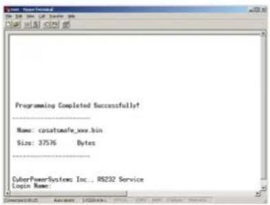
Programming Completed Successfully! Name: casatomefe_xxx.bin Size: 37576 Bytes CyberPowerSystems Inc., RS232 Service Login Name:LCD
Update the following file to upgrade the firmware.
- cpsatslafw_xxx.bin
Note that the XXX is not part of the file name but is where the version number in the filename is given.
Use the following steps to upgrade the firmware.
- Download the latest firmware from www.cyberpower.com.
- Extract the file to "C:\".
- Open Hyper Terminal to connect the ATS PDU and use the command @NEW".
Note: In order for Hyper Terminal to interact with the ATS PDU, the PC/server must be connected directly to the ATS PDU via the serial port.
(1). Use the included RJ45/DB9 serial port connection cable. Attach one end to the serial port on the front of the ATS PDU, and the other end to the PC/server.
(2). Open the Hyper Terminal software on your PC and select a name and icon for the connection.
(3). Setup the COM port settings using the following values.
* Bits per second: 38400
* Data bits: 8
* Parity: None
* Stop bits: 1
* Flow control: None
Firmware Upgrade
text_image
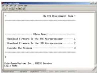
CyberPowerSystems Inc., 85232 Service Login Name: mgy- The ATS PDU will reboot and show main menu on Hyper Terminal.

text_image
C) COPYRIGHT 2013 CyberPowerSystems EXP Application (Version 0.8.1) By AIS Development Team [Main Menu] Download Firmware to the AIS Microprocessor ———— 1 Download Firmware to the LCD Microprocessor ———— 2 Execute The Program ———— 3- Press "2" to select LCD upgrade.
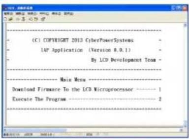
text_image
(C) COPYRIGHT 2012 CyberPowerSystems IAP Application (Version 0.0.1) By LCD Development Team ---- Main Menu ---- Download Firmware To the LCD Microprocessor ---- 1 Execute The Program ---- 2- Press "1".

text_image
C) COPYRIGHT 2013 CyberPowerSystems IAP Application (Terminal 0.9.1) By LCD Development Team Main Menu Download Firmware To the LCD Microprocessor ———— 1 Execute The Program ———— 2 Waiting for the file to be sent ... (press 'a' to short) CCCCCC- Select Transfer > Send File.
text_image
test - HyperTerminal File Edit View Call Transfer Help Send File... Receive File... Capture Text... Send Text File... Capture to Printer- Note that the Ymodem protocol and file "C:\cpsatslafw_xxx.bin" are selected in Hyper Terminal.
Firmware Upgrade
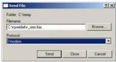
text_image
Send File Folder: C:\temp Filename: C:\cpwstdw_soc.bin Browse... Protocol: Tmodem Send Close Cancel9 The download progress window will open after you click the Send button.

text_image
Modem file send for test Sending: C:\quanta\box.x.bin Packet: 0 Error checking CRC File size OK Reties: 3 Total reties: 3 Files: 1 of 1 Last error: Unrequested response File: 0K of 8K Elapsed: Remaining Throughput: Cancel cpu/bpi- After uploading the binary file, Hyper Terminal will be shown as below.

text_image
Programming Completed Successfully! Name: cpsslsafe_xxx.bin Size: 37576 Bytes CyberPowerSystems Inc., 85232 Service Login Name:You can see if the firmware upgrade is successful by checking the "CyberPower System Firmware Version" after login.
Note : 1. Please do not turn the ATS PDU off and ensure the quality of selected source power when processing firmware upgrade. The ATS PDU will not perform the ATS function when upgrading firmware.
- Press "3" to exit the main menu of firmware upgrade.
text_image
By AIS Development Team [Main Menu] Download Firmware In the AIS Microprocessor ———— 1 Download Firmware In the LCD Microprocessor ———— 2 Execute The Program ———— 3 CyberPowerSystems Inc., RS232 Service Login NameRMCARD
There are two files to update in order to upgrade the firmware:
- cpsrm2scfw_XXX.bin
- cpsrm2scdata_XXX.bin
Note that the XXX is not part of the file name but is where the version number in the filename is given.
Option 1: Using FTP Command
Use the following steps to upgrade the firmware.
- Download the latest firmware.
- Extract the downloaded files to "C:\".
- Open a command prompt window.
- Login to the CyberPower Remote Management Card with FTP command, in the command prompt type:
Firmware Upgrade
(1) ftp
(2) ftp > open
(3) To [current IP address of RMCARD] [port]; e.g., To 192.168.22.126 21
(4) Input USER NAME and PASSWORD (same as the administrator account in web user interface)
- Upload the cpsrm2scfw_XXX.bin, type:
ftp > bin
ftp > put cpsrm2scfw _XXX.bin
- Upgrade is now complete, type:
ftp > quit
- The system will reboot after you type "quit".
- Login to the FTP again as step 4.
- Upload cpsrm2scdata _XXX.bin, type:
ftp > bin
ftp > put cpsrm2scdata _XXX.bin
- Upgrade complete, type
ftp > quit
- The system will reboot after you type "quit".
Option 2: Using Upgrade and Configuration Utility Tool
(Bulk Firmware Upgrade Tool)
Use the following steps to upgrade the firmware.
- Install the CyberPower Upgrade and Configuration Utility tool available for download at www.cyberpower.com.
- After installation completes, run the "Upgrade and Configuration Utility".
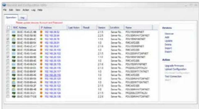
- The main window of the Upgrade and Configuration Utility tool program is shown in below figure. The configuration tool will display all CyberPower Remote Management devices present on the local network subnet. The "Discover" button is used to search the local network subnet again.
Note: You can click "View" to select the items you want to view.
text_image
Request and Configuration Utility File Edit View Action Log Help Operation Log New update services Account and Password MNC Address IP Address Last Action Result Version Location Name 00-00-15-40-ZC-08 152 160.26.52 2.1.5 Server No.: PCU153W8PNET 00-00-15-40-S9-90 152 160.26.54 2.2.5 Server No.: PCU03W4V72PNET 00-00-15-40-BF-C 152 160.26.76 1.1.0 Server No.: PCU05W4V4NET 00-00-15-40-BF-A 152 160.26.81 1.0 Server No.: RICARD205 00-00-15-40-ZC-47 152 160.26.97 2.1.9 Server No.: PCU153W8PNET 00-00-15-40-BF44 152 160.26.103 1.0 Server No.: RICARD205 00-00-15-40-LF-D 152 160.26.102 2.1.5 Server No.: PCU03W4V72PNET 00-00-15-40-BF-ME 152 160.26.104 1.1.0 Server No.: PCU03W4V4NET 00-00-15-40-BF-E 152 160.26.106 1.0 Server No.: RICARD205 00-00-15-40-BF-G4 152 160.26.115 2.1.6 Server No.: PCU153W8PNET 00-00-15-40-D3The main window of the "Upgrade and Configuration Utility" program
- Check the boxes to select the devices you wish to upgrade, and select "Update" on the right to update the device user account and password. Once the update is confirmed, the status icon next to the IP Address will change from orange to green.
Note: You must update the device user account and password credentials before firmware upgrade.
- Select the devices you wish to upgrade by checking their respective checkbox and select "Upgrade Firmware".
Note: You can upgrade the firmware of multiple devices that use the same firmware files (Bulk firmware upgrade).
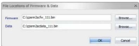
- Select the Firmware and Data files and click "OK", as shown in below figure.
text_image
File Locations of Firmware & Data Firmware C:\cpsrm2scfw_111.bin Data C:\cpsrm2scdata_111.bin Browse... Browse... OK CancelThe File Locations of Firmware & Data window
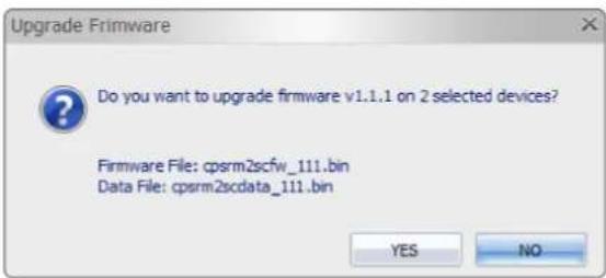
- Click "Yes" to start firmware upgrade on selected devices, as shown in below figure.
Firmware Upgrade
text_image
Upgrade Firmware Do you want to upgrade firmware v1.1.1 on 2 selected devices? Firmware File: cpsrm2scfw_111.bin Data File: cpsrm2scdata_111.bin YES NOConfirm Upgrade Firmware message window
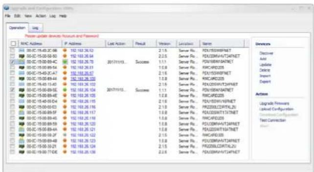
- If the firmware upgrade is implemented, you will see the Result in the main window, as shown in below figure.
text_image
Press update devices Account and Password NHC Address P Address Last Action Result Version Location Name 00-00-15-00-2C-08 152.153.26.12 00-00-15-00-08-03 152.153.26.04 00-00-15-00-09-0C 152.153.26.78 00-00-15-00-09-54 152.153.26.23 00-00-15-00-40-2C-07 152.153.26.07 00-00-15-00-09-47 152.153.26.23 00-00-15-00-09-53 152.153.26.23 00-00-15-00-11-43 152.153.26.12 00-00-15-00-09-5E 152.153.26.154 00-00-15-00-09-4E 152.153.26.126 00-00-15-00-09-44 152.153.26.15 00-00-15-00-09-43 152.153.26.16 00-00-15-00-09-49 152.153.26.17 00-00-15-00-09-48 152.153.26.18 00-00-15-00-09-49 152.153.26.19 00-00-15-00-18A 152.153.26.21 00-00-15-00-18A 152.153.26.22 00-00-15-00-18A 152.153.26.23 00-00-15-00-18A 152.153.26.24 00-00-15-00-17-CG 152.153.26.26 Success: Server Pu, PEU/SDW/NTNET Server Pu, PEU/SDW/NTNET Server Pu, PEU/SDW/NTNET Server Pu, PEU/SDW/NTNET Server Pu, PEU/SDW/NTNET Server Pu, PEU/SDW/NTNET Server Pu, PEU/SDW/NTNET Server Pu, PEU/SDW/NTNET Server Pu, PEU/SDW/NTNET Server Pu, PEu/SDW/NTNET Server Pu, PEU/SDW/NTNET Server Pu, PEU/SDW/NTNET Server Pu, PEU/SDW/NTNET Server Pu, PEU/SDW/NTNET Server Pu, PEU/SDW/NTNET Server Pu, PEU/SDW/NTNET Server Pu, PEU/SDW/NTNET Server Pu, PEU/SDW/TNTNET Server Pu, PEU/SDW/TNTNET Server Pu, PEU/SDW/TNTNET Server Pu, PEU/SDW/TNTNET Server Pu, PEU/SDW/TNTNET Server Pu, PEU/SDW/TNTNET Server Pu, PEU/SDW/TNTNET Server Pu, PEU/SDW/TNTNET Server Pu, PEU/SDW/TNTNET Success: Server Pu, PEU/SDW/TNTNET Server Pu, PEU/SDW/TNTNET Server Pu, PEU/SDW/TNTNET Server Pu, PEU/SDW/TNTNET Server Pu, PEU/SDW/TNTNET Server Pu, PEU/SDW/TNTNET Server Pu, PEU/SDW/TNTNET Server Pu, PEU/SDW/TNTNET Server Pu, PEu/SDW/TNTNET Server Pu, PEu/SDW/TNTNET Server Pu, PEu/SDW/TNTNET Server Pu, PEu/SDW/TNTNET Server Pu, PEu/SDW/TNTNET Server Pu, PEu/SDW/TNTNET Server Pu, PEu/SDW/TNTNET Server Pu, PEu/SDW/TNTNET Server Pu, PEu/SDW/DRTALZI 2 Server Pu, PEu/SDW/DRTALZI 2 Server Pu, PEu/SDW/DRTALZI 2 Server Pu, PEu/SDW/DRTALZI 2 Server Pu, PEu/SDW/DRTALZI 2Firmware upgrade success in the main window
Troubleshooting
| Problem Possible Cause Solution | ||
| ATS PDU outlets do not provide power to connected equipment | 1. Breaker tripped2. Power cord is not properly plugged in | Reset Breaker, check the plug to insure its connected correctly. If the problem remains, contact technical support. |
| Amperage displayed on LCD screen exceeds the units capability | Overload | The load indicator shows red when overload. Reduce the load on the ATS PDU until the overload is gone. If the problem remains, contact technical support. |
| Circuit breakers have tripped | 1. Sustained overload2. Excessive ambient or internal temperatures3. Faulty breaker | Reset Breaker.If the problem remains, contact technical support. |
Conformance Approvals
FCC Warning
WARNING!! This equipment has been tested and found to comply with the limits for a Class A Digital Device, pursuant to Part 15 of the FCC Rules. These limits are designed to provide reasonable protection against harmful interference in residential installation. This equipment generates, uses and can radiate radio frequency energy and, if not installed and used in accordance with the instruction manual, may cause harmful interference to radio communications. Operation of this equipment in a residential area is likely to cause harmful interference in which case the user will be required to correct the interference at their own expense.
Any special accessories needed for compliance must be specified in the instruction.
This device complies with part 15 of the FCC Rules. Operation is subject to the following two conditions: (1) This device may not cause harmful interference, and (2) this device must accept any interference received, including interference that may cause undesired operation.
Notice: (1) An unshielded-type power cord is required in order to meet FCC emission limits and also to prevent interference to the nearby radio and television reception. It is essential that only the supplied power cord is used. (2) Use only shielded cables to connect I/O devices to this equipment.
Note: THE MANUFACTURER IS NOT RESPONSIBLE FOR ANY RADIO OR TV INTERFERENCE CAUSED BY UNAUTHORIZED MODIFICATIONS TO THIS EQUIPMENT. SUCH MODIFICATIONS COULD VOID THE USER'S AUTHORITY TO OPERATE THE EQUIPMENT.
The Class A digital apparatus meets all requirements of the Canadian Interference-Causing Equipment Regulation.
This is a class A product. In a domestic environment this product may cause radio interference in which case the user may be required to take adequate measures.
Customer Service & Warranty
Product Registration
Thank you for purchasing a CyberPower product. Prompt product registration entitles coverage under the Limited Warranty and also allows the opportunity to be notified of product enhancements, upgrades, and other announcements.
Registration is quick and easy at www.cyberpower.com/registration.
CyberPower International
Feel free to contact our Tech Support department with installation, troubleshooting, or general product questions.
Cyber Power Systems, Inc. www.cyberpower.com
For USA and Canada:
4241 12th Ave East, Suite 400 Shakopee, MN 55379 Toll-free: (877) 297-6937
For all other regions:
Please visit our website for local contact information.
Customer Service & Warranty
Limited Warranty
Read the following terms and conditions carefully before using the CyberPower ATS PDU series. By using the Product, you consent to be bound by and become a party to the terms and conditions of this Limited Warranty. If you do not agree to the terms and conditions of this Warranty, you should return the Product for a full refund prior to using it.
Who Is Providing This Warranty?
Cyber Power Systems, Inc. provides this Limited Warranty.
What Does This Warranty Cover?
This warranty covers defects in materials and workmanship in the Product under normal use and conditions.
What Is The Period of Coverage?
For USA and Canada, CyberPower provides a 3-Year limited warranty to the original purchaser who owns the Product. For other regions, please contact your local CyberPower sales team for more information.
Who Is Covered?
This warranty only covers the original purchaser. Coverage ends if you sell or otherwise transfer the Product.
How Do You Get Service?
- You can use the contact information mentioned above for instructions.
- When you contact CyberPower, identify the Product, the Purchase Date, and the item(s) of Connected Equipment.
- You must provide a purchase receipt (or other proof of the original purchase) and provide a description of the defect.
What Will We Do To Correct Problems?
CyberPower will inspect and examine the Product.
If the Product is defective in material or workmanship, CyberPower will repair or replace it at CyberPower's expense, or, if CyberPower is unable to or decides not to repair or replace the Product (if defective) within a reasonable time, CyberPower will refund to you the full purchase price you paid for the Product (purchase receipt showing price paid is required).
Who Pays for Shipping?
We pay when we send items to you; you pay when you send items to us.
What Are Some Things This Warranty Does Not Cover?
- This Warranty does not cover any software that is damaged or needs to be replaced due to the failure of the Product or any data that is lost as a result of the failure or the restoration of data or records, or the reinstallation of software.
- This Warranty does not cover or apply to: misuse, modification, operation or storage outside environmental limits of the Product or the equipment connected to it, nor for damage while in transit or in storage, nor if there has been improper operation or maintenance, or use with items not designed or intended for use with the Product, such as laser printers, appliances, aquariums, medical or life support devices, etc.
What Are The Limitations?
- This Warranty does not apply unless the Product and the equipment that was connected to it were connected to properly wired and grounded outlets (including compliance with electrical and safety codes of the most current electrical code), without the use of any adapters or other connectors.
- The Product must have been plugged directly into the power source and the equipment connected to the Product must be directly connected to the Product and not "daisy-chained" together in serial fashion with any extension cords, another Product or device similar to the Product, surge suppressor, or power tap. Any such installation voids the Limited Warranty.
- The Product and equipment connected to it must have been used properly in a suitable and proper environment and in conformance with any license, instruction manual, or warnings provided with the Product and the equipment connected to it.
- The Product must have been used at all times within the limitations on the Product's VA capacity.
- The sole and exclusive remedies of the Initial Customer are those provided by this Warranty
Appendix A-Hyper Terminal
Hyper Terminal software can be used for basic ATS PDU configuration. In order for Hyper Terminal to interact with the ATS PDU, the PC/server must be connected directly to the ATS PDU via the serial port with the included RJ45/DB9 serial port connection cable. It utilizes a text-based interface and menu system. Navigation through the interface is done by typing the number of the menu option and pressing the Enter key. Setup the COM port settings using the following values.
* Bits per second: 38400
* Data bits: 8
* Parity: None
* Stop bits: 1
* Flow control: None
Note: The session will timeout and logout after 3 minutes of inactivity. Menu options are shown below:
[Main Menu]
- Utility Configuration
- Outlet Manager (Switched Series Only)
- Load Configuration
- Network Settings
- System Configuration
- Account Settings
- Configure System to Default
- Logout
[Utility Configuration]
- Preferred Source: A
- Sensitivity: High
- Voltage Range: Medium
- Frequency Deviation: 1 Hz
- Nominal Voltage: 230 V
- Wide Voltage Range: 30 V
- Medium Voltage Range: 23 V
- Narrow Voltage Range: 16 V
- Set Load Restriction (Switched Series Only)
[Outlet Manager]
- Outlet Control
- Outlet Configuration
[Load Configuration]
- Device Threshold Configuration
- Bank 1 Threshold Configuration
- Bank 2 Threshold Configuration
- Bank 3 Threshold Configuration
[Network Setting]
Physical MAC Address: 00-0C-15-00-00-01
- System IP: 192.168.20.240
- Subnet Mask: 255.255.255.0
- Default Gateway: 192.168.20.254
- DHCP: Enabled
- Http Port: 80
- Http Access: Enabled
[System Configuration]
- Name: PDU15SW10ATNET
- Location: Server Room
- Contact: Administrator
[Account Setting]
- Administrator
[Configure System to Default]
Sure to Configure System to Default
- Reset ATS PDU
- Reset ATS PDU (TCP/IP Settings Reserved)
Appendix B-Power Device Network Utility
Overview
The CyberPower Power Device Network Utility is an easy-to-use interface which is used for establishing IP addresses on CyberPower ATS PDUs.
Installation
Step 1. Download the Power Device Network Utility software available at www.cyberpower.com.
Step 2. Select Next in the software wizard (Shown in Figure 1).
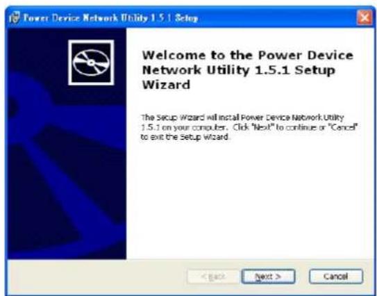
text_image
Power Device Network Utility 1.5.1 Setup Welcome to the Power Device Network Utility 1.5.1 Setup Wizard The Setup Wizard will install Power Device Network Utility 1.5.1 on your computer. Click "Next" to continue or "Cancel" to exit the Setup Wizard.Figure 1
Step 3. Choose an installation directory. Select Next (Shown in Figure 2).
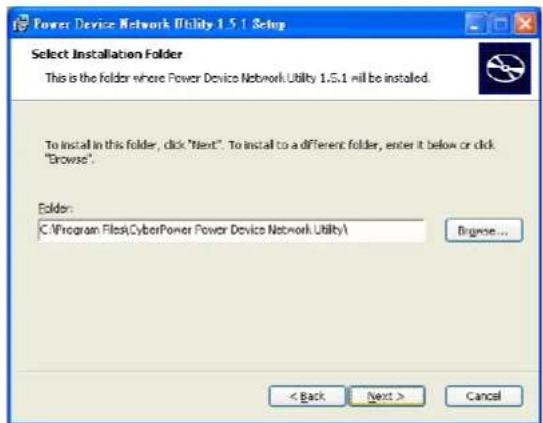
text_image
Power Device Network Utility 1.5.1 Setup Select Installation Folder This is the folder where Power Device Network Utility 1.5.1 will be installed. To install in this folder, click "Next". To install to a different folder, enter it below or click "Browse". Folder: C:\Program Files\CyberPower Power Device Network Utility\ Browse... < Back Next > CancelFigure 2
Step 4. Select Install to confirm the settings and install (Shown in Figure 3).
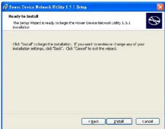
text_image
Power Device Network Utility 1.5.1 Setup Ready to Install The Setup Wizard is ready to begin the Power Device Network Utility 1.5.1 Installation Click "Install" to begin the installation. If you want to review or change any of your installation settings, click "Book". Click "Cancel" to exit the wizard. < Back Install CancelFigure 3
Appendix B-Power Device Network Utility
Step 5. Select Finish to finalize the installation (Shown in Figure 4).
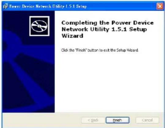
text_image
Power Device Network Utility 1.5.1 Setup Completing the Power Device Network Utility 1.5.1 Setup Wizard Click the 'Finish' button to exit the Setup Wizard. < Back Finish CancelFigure 4
Launch Program
To launch the Power Device Network Utility and get started, select Programs from the Start menu in Windows and locate the new folder and icons for Power Device Network Utility. Select Power Device Network Utility from the program folder (Shown in Figure 5).
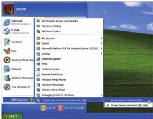
text_image
Jason Internet Internet Explorer E-mail Outlook Express WordPad MSN Windows Media Player Netropad Windows Messenger Tour Windows XP Set Program Access and Defaults Windows Catalog Windows Update Accessories Genes Microsoft Platform SDK for Windows Server 2003 R2 Startup Internet Explorer MSN Outlook Express Remote Assistance Windows Media Player Windows Messenger Windows Movie Maker Debugging Tools for Windows All Programs CyberPower Power Devices Network Utility Log Off Turn Off Computer Power Device Network Utility Help StartFigure 5. Power Device Network Utility
Getting Started
The Power Device Network Utility scans the network for devices with MAC addresses that match CyberPower network hardware. Once found, the device(s) can then be figured with a specific IP address, subnet mask, and gateway address. This allows the device(s) to function properly on the network and interface with CyberPower Management Console.
Step 1. Select the appropriate ATS PDU from the Equipment List (Shown in Figure 6).
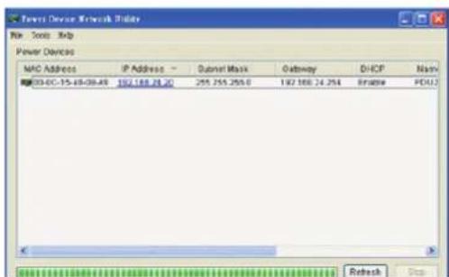
text_image
Forest Device Network Provider File Tools Help Power Devices MAC Address IP Address Subset Mask Gateway DHCP Mark 03-0C-15-48-08:49 157.188.28.2C 255.255.255.0 192.188.24.254 Bridge PDAU2 Refresh StopFigure 6. Equipment List
Note: If the ATS PDU does not appear on the list, click the Refresh button to rescan the network. If it still does not appear, ensure that the ATS PDU is turned on and is installed correctly. Pressing Stop will cancel the scan/refresh process.
Note: If your computer has a software firewall installed, you may see a Windows Security Alert message (Shown in Figure 7).
In Windows XP SP2, the default firewall alert message is shown as Figure 7. You need to allow the Power Device Network Utility access through the firewall.
Appendix B-Power Device Network Utility

text_image
Windows Security Alert To help protect your computer. Windows Firewall has blocked some features of this program. Do you want to keep blocking this program? Name: Power Device Network Utility Publisher: Unknown Keep Blocking Unlock Ask Me Later Windows Firewall has blocked this program from accepting connections from the Internet or a network. If you recognize the program or trust the publisher, you can unlock it. When should I unlock a program?Figure 7. Windows Security Alert
Step 2. Assign a valid IP Address to the ATS PDU.
With the appropriate device selected from the Equipment List, open the Network Settings menu (shown in Figure 8) [Tools=>Device Setup]. In the Device Network Setting Menu, enter a valid IP address, subnet mask, and gateway address to setup the ATS PDU device.

text_image
Device Network Settings Device MAC Address: 00-0C-15-40-08-A9 Using DHCP Yes No IP Address 192 . 168 . 24 . 20 Subnet Mask 255 . 255 . 255 . 0 Gateway 192 . 168 . 24 . 254 Save CancelFigure 8. Network Setting Menu (Device Setup)
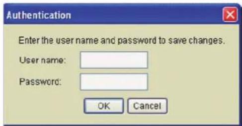
Step 3. Authentication
Enter the user name and password of the ATS PDU at the Authentication menu (shown in Figure 9).
Note: The default username is "cyber" and the default password is "cyber".
text_image
Authentication Enter the user name and password to save changes. User name: Password: OK CancelFigure 9. Authentication screen
Advanced Settings
Timeout Settings
The Timeout Setting (Shown in Figure 10). [Edit=>Timeout Settings] is used to specify the wait time when scanning for network ATS PDUs. When there are many devices on the local network, it may take extended periods of time to locate all the devices. The timeout function is used to limit the search time. The default setting is 3 seconds. Valid values are 3 to 60 seconds.

text_image
Timeout Setting The time to wait all devices response in 3 seconds. OK Cancel DefaultFigure 10. Timeout Setting
CyberPower
Cyber Power Systems, Inc.
www.cyberpower.com