ZIPT471 - Security Camera Speco Technologies - Free user manual and instructions
Find the device manual for free ZIPT471 Speco Technologies in PDF.

User questions about ZIPT471 Speco Technologies
0 question about this device. Answer the ones you know or ask your own.
Ask a new question about this device
Download the instructions for your Security Camera in PDF format for free! Find your manual ZIPT471 - Speco Technologies and take your electronic device back in hand. On this page are published all the documents necessary for the use of your device. ZIPT471 by Speco Technologies.
USER MANUAL ZIPT471 Speco Technologies
About the User's Guide
Before operating the unit, please read this user's guide thoroughly and retain it for future reference.
Cautions

text_image
CAUTION RISK OF ELECTRIC SHOCK DO NOT OPEN CAUTION: TO REDUCE THE RISK OF ELECTRIC SHOCK, DO NOT REMOVE COVER (OR BACK). NO USER SERVICEABLE PARTS INSIDE. REFER SERVICING TO QUALIFIED SERVICE PERSONNEL.Explanation of Graphic Symbols

This symbol indicates the presence of important operating and maintenance (servicing) instructions in the literature accompanying the product.

This symbol indicates the presence of “dangerous voltage” within the product’s enclosure that may be of sufficient magnitude to constitute a risk of electric shock, property damage, personal injury, or death.
WARNING
To reduce a risk of fire or electric shock, do not expose this product to rain or moisture.
CAUTION
Changes or modifications not approved by the manufacturer will void the warranty of the product. Using an incompatible battery may increase the risk of fire or explosion. Replace only with the same or equivalent type battery recommended by the manufacturer. Discard used batteries according to manufacturer's instructions.
These Precautions must be followed for Safety Reasons

Warning
- Do not use if the unit emits smoke.
- Do not disassemble the unit.
- Do not place any heavy or sharp objects on the unit.
- Do not place on uneven surface.
- Do not expose to shock or vibration.
- Do not move the unit when the unit is powered on.
- Do not block, and allow dust to accumulate in the air vents.
- Do not restrict airflow of the unit; doing so can damage the unit.
- Only qualified and experienced personnel should perform installation and servicing.
- Turn off the power of the DVR when connecting Cameras, Audio or Sensor Cables.
- The manufacturer is not responsible for any damage caused by improper use of the product or failure to follow instructions for the product.
- The manufacturer is not responsible for any problems caused by or resulting from the user physically opening the DVR for examination or attempting to repair the unit.
- The manufacturer may not be held liable for any issues with the unit if the warranty seal is removed.
Product Components
Please make sure the following components are included as specified below.
| DVR Unit |  |
| Remote Control | 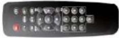 |
| Battery1.5V (AAA x 2EA) |  |
| Quick Start Guide & Quick User Guide |  |
| Mouse for D4VT/D8VT/D16VT |  |
| Software & Manual CD |  |
| Adaptor(DC12V 3A for D4VT, DC12V 5A for D8VT/D16VT)& Power cable (110V) | 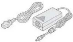 |
| Audio Cable for D16VT |  |
Specifications
| ITEM | D4VT D8VT D16VT | |||||
| Description | 960H and HD-TVI Hybrid DVR with UTC (Coaxtron) | |||||
| Video | Input | Number of Channels | 4 8 16 | |||
| Camera | 720p25/30/50/60, 1080p25/30 or NTSC/PAL | |||||
| Output | Main Monitor | HDMI and VGA (1920x1080) | ||||
| Sub Monitor(option) | CVBS or SPOT | |||||
| Audio | Input / Output (HDMI support) | 4 / 1 | ||||
| Audio Codec | G.711 | |||||
| Alarm | Sensor Input | 4 | ||||
| Alarm Output | 1 | |||||
| Serial | RS-485 | 1 | ||||
| Recording | Compression | H.264 (Main Profile) | H.264 (High Profile) | |||
| 1920x1080 Camera Input | 1920x1080 | 15fps/ch | ||||
| 1920x540 | 15fps/ch | |||||
| 1280x720 | 15fps/ch | |||||
| 640x360 | 15fps/ch | |||||
| 1280x720 Camera Input | 1280x720 | 25/30fps/ch | ||||
| 640x360 | 25/30fps/ch | |||||
| Analog Camera Input | 960H | 25/30fps/ch | ||||
| D1 | 25/30fps/ch | |||||
| CIF | 25/30fps/ch | |||||
| Recording Quality Grade | 5 Levels | |||||
| Recording Mode | Continuous / Motion / Sensor / Schedule / Manual | |||||
| Pre Recording | Max. 20 Minutes | |||||
| Post Recording | Max. 60 Seconds | |||||
| Playback | Search | Date/Time, Event, Archive, Log | ||||
| Multi-Decoding | 1, 4 1, 4, 8 1, 4, 9, 16 | |||||
| Playback Speed | x0.25, x0.5, x2, x4, x8, x16, x32, x64 | |||||
| Backup | Media | USB drive, External HDD, Network | ||||
| Format | BMP, AVI, Proprietary Format | |||||
| Huge Backup | Yes (Max. 24 hours) | |||||
| Storage | HDD | Capacity of 1 HDD | Up to 4TB | |||
| Internal HDDs | 2 2 2 | |||||
| e-SATA | None None None | |||||
| USB | Front | 1 | ||||
| Rear | 1 | |||||
| User I/F | Input Method | IR, Mouse, Keyboard Controller | ||||
| Network | Interface | 10/100 Base-T | 10/100/1000 Base-TX | |||
| Dynamic DNS | Yes (Free DDNS) | |||||
| Dual Encoding for Network | Yes | |||||
| Features | Digital Zoom | Yes | ||||
| DLS (Day Light Saving) | Yes | |||||
| NTP (Network Time Protocol) | Yes | |||||
| S.M.A.R.T | Yes | |||||
| Internal Beep | Yes | |||||
| Multi-Language | Yes | |||||
| e-mail Notification | Yes | |||||
| Network Access | 3G Mobile | iPad / iPhone / Android | ||||
| Web Viewer | Windows (IE, Chrome, Firefox, Safari) | |||||
| PC Client | Single / Multi Client and CMS (64 channels) | |||||
| Remote Setup and Upgrade | Yes | |||||
| Power DC | 12V 3A DC 12V 5A DC Power Supply Voltage | |||||
| Temperature | Operation | 5°C ~ 40°C | ||||
| Storage | -10°C ~ 50°C | |||||
| Humidity | Operation | 20% ~ 80% (Non-condensing) | ||||
| Weight | Unit Weight (Gross weight) | 1.5Kgs (3.0Kgs) | ||||
| Dimension | Unit Dimension (W x H x D) | 340mm(13.4") x 262mm(10.31") x 63mm(2.48") | ||||
Please note that specifications and unit exterior design are subject to change without notification.
Table of Contents
- Main Features 9
- Initial Boot up Process.... 10
2-1. Initial Boot up and Basic Time Setup....10
2-2. Setting Daylight Saving Time ....10
2-3. Setting NTP (Network Time Protocol)....12
2-4.EZ Setup....15
- Name, Function and Connection ...... 17
3-1. Front Panel 17
3-2. Connectors ...... 17
3-3. Remote Control....19
- Setting up the DVR.... 20
4-1. Setup – Main Live Screen....20
4-2. Setup – System Mode....20
4-2-1. How to use 'Cloud' 25
4-3. Setup – Record Mode ....26
4-3-1. Recording Schedules....28
4-4. Setup – Device Mode....28
4-4-1. Digital Deterrent....30
4-4-2. Keyboard Controller & PTZ Setup....31
4-5. Setup – Display Mode 35
4-6. Setup – Network Mode....36
4-6-1. Network Types ....37
4-6-2. DDNS 38
4-6-3. Network Port and Web Port....38
4-6-4. Network Stream 39
4-7. Setup – User Management Mode......40
4-8. Setup – Storage Mode .... 43
4-9. Setup - Config Mode 44
4-9-1. Software Upgrade....45
- Live, Search and Playback.... 47
5-1. Live View 47
5-1-1. PTZ Control 50
5-2. Digital Zoom in Live and Playback Screen 51
5-3. Search Screen....51
5-3-1.EZSearch....52
5-3-2. Smart Search....53
5-3-3. Time Line Search....55
5-3-4. Event Search ....55
5-3-5. Go To First Time....56
5-3-6. Go To Last Time....56
5-3-7. Go To Specific Time ....56
5-3-8. Archive List ....57
5-3-9. Log List....57
5-4. Play Mode....57
6. Export and Back Up.... 59
6-1. Still Image Backup onto USB Flash Drive....59
6-2. Video Backup onto USB Flash Drive during playback 60
6-3. EZCopy: Video Backup onto USB Flash Drive during playback....61
6-4. Transferring Still Images or Video from the ARCHIVE List....62
6-5. Playback of Backup Video....63
6-5-1. AVI Format....63
6-5-2. NSF Format 63
7. Network Access Using the Multi-Sites Network Viewer 64
7-1. Overview....64
7-2. PC Requirements....64
7-3. Installation of the Program 65
7-4. Live Window....66
7-4-1.Main User Interface....66
7-4-2. Control Buttons....67
7-5. Search and Playback Window....68
7-5-1.Main User Interface....68
7-5-2. Main Control Panel 69
7-5-3. SMART SEARCH ....71
Setup of SpecoTech Multi Client....73
7-6-1. General....73
7-6-2. Event 74
7-6-3. Record....75
7-6-4. Display....76
7-6-5. Language....76
7-6-6. About 77
7-7. Remote Setup....78
7-7-1. System....79
7-7-2. Record....81
7-7-3. Device....82
7-7-4. Display....83
7-7-5. Network 83
7-7-6.User Management 84
7-7-7. Storage 84
7-7-8. Remote Upgrade....84
7-8. Operation....85
7-8-1. Addition, Delete, and Modify of DVR Sites 85
7-8-2. Connect and Disconnect....87
7-8-3. Still-image Capture During Live....88
7-8-4. Recording Video on Local PC During Live 89
7-8-5. Local Playback and Remote Playback 90
7-8-6. AVI Backup during Playback 92
-
Network Access Using the Web-Browser Viewer 94
-
Network Access Using the Smart Phone Viewer.... 96
9-1. App Viewer for iPhone....96
9-1-1. Live....96
9-1-2.PTZ Control 98
9-1-3. Playback....98
9-2. App Viewer for Android Phone....99
9-2-1. Live 99
9-2-2. Playback....100
9-2-3.PTZ Control 101
APPENDIX: Network Connection - LAN 102
APPENDIX: Network Connection – Internet and DDNS.... 103
1. Main Features
■ Easy Record, Copy and Setup
■ Easy Search by Thumbnail Preview
■ Easy Copy
■ Digital Deterrent function
■ H.264 high quality compression saves HDD space
■ Simultaneous live view/playback while continuing to record/network transfer or backup
■ Remote monitoring/recording/playback/configuration and control via internet
■ 4 Channel Audio Recording
■ Switch between low and high quality stream during simultaneous Continuous + Motion or Continuous + Sensor recording modes for storage optimization
NOTE: Under federal law, The Fourth Amendment to the U.S. Constitution, Title III of the Omnibus Crime Control and Safe Streets Act of 1968, as amended by the Electronic Communications Privacy Act of 1986 (18 U.S.C. § 2510, et seq.), and the Foreign Intelligence Surveillance Act of 1978 (50 U.S.C. 1801, et seq.) permit government agents, acting with the consent of a party to a communication, to engage in warrantless interceptions of telephone communications, as well as oral and electronic communications.
■ Automatic camera detection (Plug & Play)
■ Covert camera operation provides enhanced security and administrator control
■ Dynamically programmable recording priority, motion detection, alarms and scheduling
■ Simple and Easy Graphic User Interface
■ HDMI Output
■ Password to secure access
■ Network software supports 10/100Mbps
■ USB 2.0 port for video clip exporting and easy firmware upgrade via USB Flash Drive
■ Exclusive File Format Backup and Player
- Variety of ways to Remote access via SecureGuard® CMS, SpecoTech Multi-Client Software, WebViewer, and Mobile App
■ S.M.A.R.T. (Self-Monitoring, Analysis, and Reporting Technology for HDD)
2. Initial Boot up Process
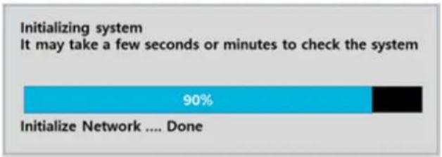
2-1. Initial Boot up and Basic Time Setup
- During the first boot up, the following logo and message will be displayed.

text_image
speco technologies- After the logo, select the language as specified below.

text_image
Choose Language english Close Change Your Password For Cyber Security ! New select Confirm select Password Match ok1) User has to set a password before using.
Can not use '1111' when the initial boot up password set.
But user can set '1111' as a password through [Setup > User Management > Password Setup]
2) DVR will not proceed when user put the password '1111'.
bar
| Category | Value (%) | |---|---| | Initialize the system | 90 | | Initialize Network .... Done | (Not labeled) |
text_image
Select EZ Setup EZ Setup will help you to setup your SYSTEM. Please select one of the options below. • EZ Record for Date/Time and Recording Setup • EZ Network for Network Setup next >> cancel(EZ Setup Page Reference, Page 15-16)
2-2. Setting Daylight Saving Time
To enable Daylight Saving feature/NTP synchronization, take the following steps.
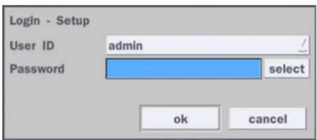
- Enter the Setup mode. The default Username is "admin" and enter a password set on the initial boot-up process.

text_image
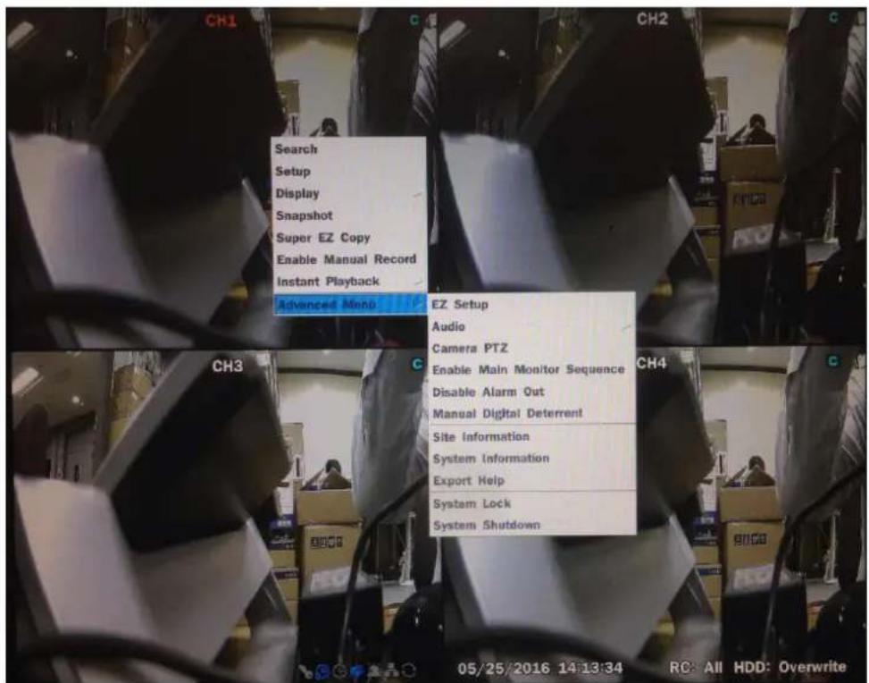
Search Setup Display Snapshot Super EZ Copy Enable Manual Record Instant Playback Adegrace Maps EZ Setup Audio Camera PTZ Enable Main Monitor Sequence Disable Alarm Out Manual Digital Detement Site Information System Information Export Help System Lock System Shutdown
text_image
Search Setup Display Snapshot Super EZ Copy Enable Manual Record Instant Playback Advanced Menu
text_image
Login - Setup User ID admin Password select ok cancel2. Go to Setup > System > Date & Time Setup
text_image
System Description select Language english / Date Display Format mm/dd/yyyy / Date & Time Setup select Client Access on / NTP Setup on / select e-Mail Setup off / select Unit Name DVR System Restart select System Shutdown select EZ Setup select System Event Notification select apply cancel- Select 'ok" from the Daylight Saving dropdown menu.
text_image
Time Display Format 24-Hour Format Time Zone GMT -5:00 (Montreal/New York) Daylight Saving USA Set Date & Time 2016 / 5 / 13 / 4 : 42 : 18 / ok cancel2-3. Setting NTP (Network Time Protocol)
- Setup > System > NTP Setup > On > Select
text_image
System Description select Language english / Date Display Format mm/dd/yyyy / Date & Time Setup select Client Access on / NTP Setup on / select e-Mail Setup off / select Unit Name DVR System Restart select System Shutdown select EZ Setup select System Event Notification select apply cancel- Select the proper GMT Time Zone.

text_image
Primary SNTP Server Pool.ntp.org select Secondary SNTP Server Time.nist.gov select Time Zone GMT -5:00 (Montreal/New York) / Connection Mode time / Connection Period 03:00 AM / ok cancelTable 2.3.1. GMT Time Zone
| State | Standard Time | Daylight-Saving Time | |
| AL | Alabama | GMT-6 | GMT-5 |
| AK | Alaska | GMT-9 | GMT-8 |
| AK | Alaska (Aleutian Islands) | GMT-10 | NA |
| AZ | Arizona | GMT-7 | NA |
| AZ | Arizona (Navajo) | GMT-7 | GMT-6 |
| AR | Arkansas | GMT-6 | GMT-5 |
| CA | California | GMT-8 | GMT-7 |
| CO | Colorado | GMT-7 | GMT-6 |
| CT | Connecticut | GMT-5 | GMT-4 |
| DC | District of Columbia | GMT-5 | GMT-4 |
| DE | Delaware | GMT-5 | GMT-4 |
| FL | Florida | GMT-5 | GMT-4 |
| FL | Florida (W) | GMT-6 | GMT-5 |
| GA | Georgia | GMT-5 | GMT-4 |
| HI | Hawaii | GMT-10 | NA |
| ID | Idaho (N) | GMT-8 | GMT-7 |
| ID | Idaho (S) | GMT-7 | GMT-6 |
| IL | Illinois | GMT-6 | GMT-5 |
| IN | Indiana | GMT-5 | GMT-4 |
| IN | Indiana (SW / NW) | GMT-6 | GMT-5 |
| IA | Iowa | GMT-6 | GMT-5 |
| KS | Kansas | GMT-6 | GMT-5 |
| KS | Kansas (W) | GMT-7 | GMT-6 |
| KY | Kentucky (E) | GMT-5 | GMT-4 |
| KY | Kentucky (W) | GMT-6 | GMT-5 |
| LA | Louisiana | GMT-6 | GMT-5 |
| ME | Maine | GMT-5 | GMT-4 |
| MD | Maryland | GMT-5 | GMT-4 |
| MA | Massachusetts | GMT-5 | GMT-4 |
| MI | Michigan | GMT-5 | GMT-4 |
| MI | Michigan (W) | GMT-6 | GMT-5 |
| MN | Minnesota | GMT-6 | GMT-5 |
| MS | Mississippi | GMT-6 | GMT-5 |
| MO | Missouri | GMT-6 | GMT-5 |
| MT | Montana | GMT-7 | GMT-6 |
| NE | Nebraska | GMT-6 | GMT-5 |
| NE | Nebraska (W) | GMT-7 | GMT-6 |
| NV | Nevada | GMT-8 | GMT-7 |
| NH | New Hampshire | GMT-5 | GMT-4 |
| NJ | New Jersey | GMT-5 | GMT-4 |
| NM | New Mexico | GMT-7 | GMT-6 |
| NY | New York | GMT-5 | GMT-4 |
| NC | North Carolina | GMT-5 | GMT-4 |
| ND | North Dakota | GMT-6 | GMT-5 |
| ND | North Dakota (W) | GMT-7 | GMT-6 |
| OH | Ohio | GMT-5 | GMT-4 |
| OK | Oklahoma | GMT-6 | GMT-5 |
| OR | Oregon | GMT-8 | GMT-7 |
| OR | Oregon (E) | GMT-7 | GMT-6 |
| PA | Pennsylvania | GMT-5 | GMT-4 |
| RI | Rhode Island | GMT-5 | GMT-4 |
| SC | South Carolina | GMT-5 | GMT-4 |
| SD | South Dakota (E) | GMT-6 | GMT-5 |
| SD | South Dakota (W) | GMT-7 | GMT-6 |
| TN | Tennessee (E) | GMT-5 | GMT-4 |
| TN | Tennessee (W) | GMT-6 | GMT-5 |
| TX | Texas | GMT-6 | GMT-5 |
| TX | Texas (W) | GMT-7 | GMT-6 |
| UT | Utah | GMT-7 | GMT-6 |
| VT | Vermont | GMT-5 | GMT-4 |
| VA | Virginia | GMT-5 | GMT-4 |
| WA | Washington | GMT-8 | GMT-7 |
| WV | West Virginia | GMT-5 | GMT-4 |
| WI | Wisconsin | GMT-6 | GMT-5 |
| WY | Wyoming | GMT-7 | GMT-6 |

NOTE: If you want the unit to automatically synchronize the local time, the Time Zone must be properly set according to your local time zone.
2-4. EZ Setup
VT Easy Setup(Click the right button on mouse > Advanced Menu > EZ Setup)
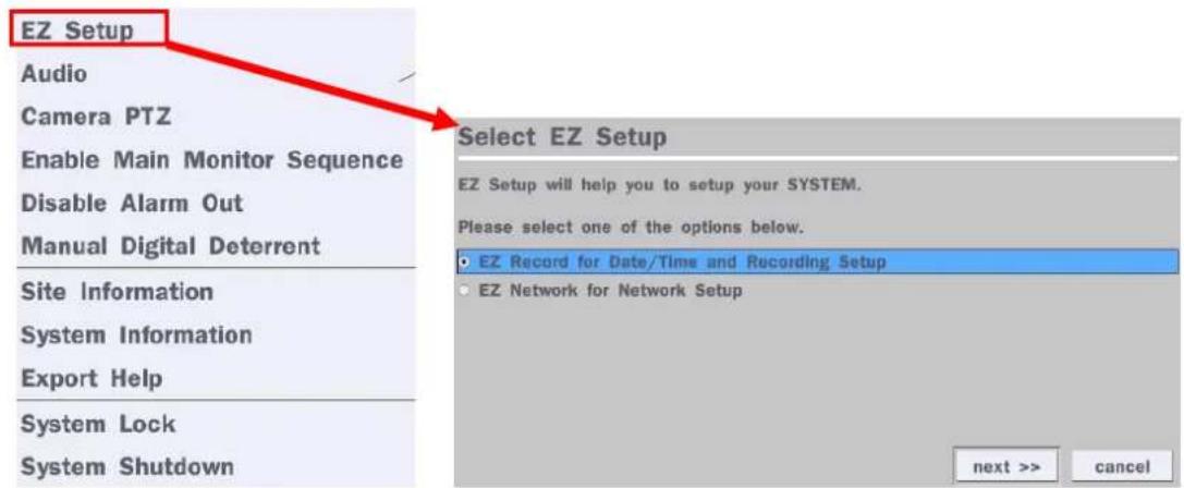
text_image
EZ Setup Audio Camera PTZ Enable Main Monitor Sequence Disable Alarm Out Manual Digital Deterrent Site Information System Information Export Help System Lock System Shutdown Select EZ Setup EZ Setup will help you to setup your SYSTEM. Please select one of the options below. • EZ Record for Date/Time and Recording Setup • EZ Network for Network Setup next >> cancelFigure 2.4. EZ Setup Screen
2.4.1. Setup Date/Time and Recording configuration

Figure 2.4.1. EZ Record Setup Procedure
① Select EZ Record for Date/Time and Recording Setup, click "next" to proceed.
② When the description of EZ Record Setup is displayed, click "next" to proceed.
③ Set up the Date/Time settings and click "next" to get to the recording setup.
④ Select the recording mode and click "next" to get to the recording setup.
⑤ Select one of options and click "next" to finish the setup.
2.4.2. EZ Network (Using an internet connection)

text_image
Select EZ Setup EZ Setup will help you to setup your SYSTEM. Please select one of the options below. • EZ Record for Date/Time and Recording Setup • EZ Network for Network Setup next >> cancel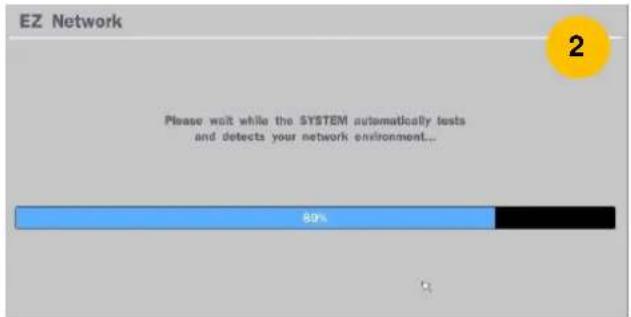
text_image
EZ Network Please wait while the SYSTEM automatically tests and detects your network environment... 80% 2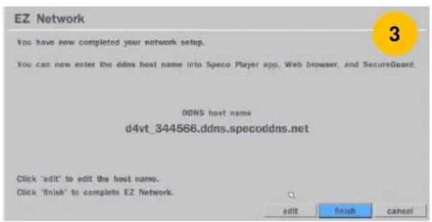
text_image
EZ Network You have now completed your network setup. You can now enter the ddns host name into Speco Player app, Web browser, and SecureGuard. DDNS host name d4vt_344566.ddns.specoddns.net Click 'edit' to edit the host name. Click 'finish' to complete EZ Network. edit Finish Cancel
text_image
Host Name d4vt_344566 ` 1 2 3 4 5 6 7 8 9 0 - = ← q w e r t y u i o p [ ] Caps a s d f g h j k l ; Enter Shift z x c v b n m , . / Shift Clear Space CloseFigure 2.4.2. EZ Network Setup Procedure
① DVR automatically checking the network and configuration by scanning in few seconds.
② DVR will show the DDNS host name when configuration is finished automatically.
③ If you need to edit the host name please select 'edit' button.
④ Everything is OK, then select 'finish'.
3. Name, Function and Connection
3-1. Front Panel

text_image
speco technologies VTFigure 3.1.1. Front panel
Table 3.1.1. Front LED and Port of DxxVT
| Name | Description |
| POWER | LED light is on when power is applied to the system. |
| HDD | LED light is on when the system is recording video data. |
| USB Port | This USB port for archiving footage into a USB device. (USB 2.0 connector) |
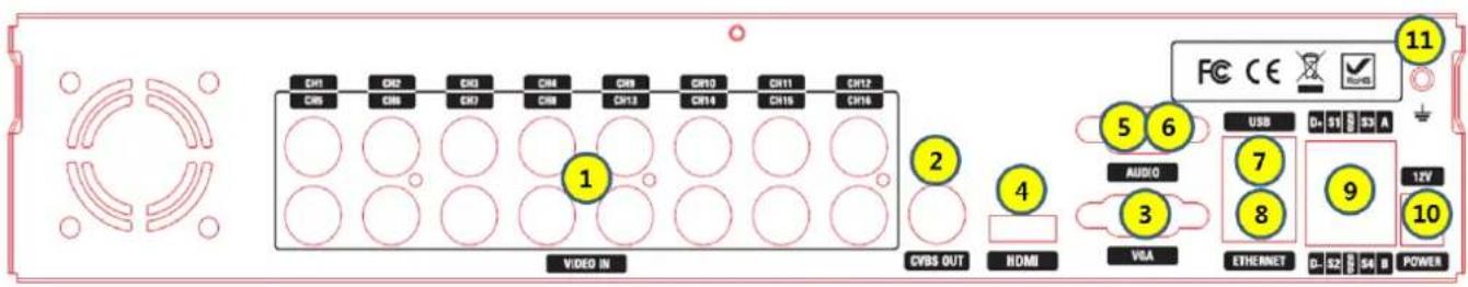
3-2. Connectors

text_image
11 FC CE AUDIO OUT 6 1 VIDEO IN 5 AUDIO IN 2 CVBS OUT 3 HDMI VGA 7 ETHERNET USB 8 9 4 3 2 1 G head REASS SENSOR ALARM 12V POWERD4VT

text_image
11 C#1 C#2 CH3 CH4 5 AUDIO IN AUDIO OUT 1 C#1 C#2 C#3 C#4 CH5 CH6 CH7 CH8 2 CVBS OUT 3 4 HDMI VGA ETHERNET 7 8 USB 9 12V 4 2 1 G Net R/W SENSOR ALARM POWERD8VT
text_image
CD1 CD2 CD3 CD4 CD5 CD6 CD7 CD8 CD9 CD10 CD11 CD12 CD13 CD14 CD15 CD16 1 2 3 4 5 6 7 8 9 10 VIDEO IN CVBS OUT HDMI USB D: 51 S 53 A AUDIO VLA ETHERNET D: 52 S 54 B POWERD16VT
Figure 3.2.1. Rear Panel Connections
① VIDEO IN: Video input port.
② VIDEO OUT:
D4VT: Switchable (Composite Video Output or Spot Monitor)
D8VT, D16VT: CVBS – Composite Video Output / SPOT – Spot Monitor
③ VGA: VGA (Video Graphics Array) output port. Connects to the PC VGA monitor.
④ HD VIDEO OUT: HDMI output port. Connections to the HDMI monitor (1920x1080).
⑤ AUDIO IN: D4VT/ D8VT: Four connectors for audio input.
D16VT: use the included audio splitter cable
⑥ AUDIO OUT: D4VT/ D8VT: One connector for audio output.
D16VT: use the included audio splitter cable.
⑦ ETHERNET: Network terminal
⑧ USB: USB terminal
⑨ SENSOR IN, ALARM OUT, RS-485: External sensor terminal, External alarm out terminal & RS-485 for PTZ Camera control
⑩ POWER: DC12V input
⑪ Ground: Use for ground port
3-3. Remote Control

text_image
1 4 6 9 11 12 14 ID E50 3 6 9 2 5 8 0 3 E50 SETUP MACUP 2 5 8 10 13Typical Remote Control
① ID: To set the remote control ID.
② REC: To start and stop manual recording
③ SEARCH: To go to SEARCH menu.
④ F/ADV:
- During playback – To move the playback position 60 seconds forward.
- During Pause – To move the playback position moves 1 frame forward
⑤ F/REW:
- During playback – To move the playback position 60 seconds back.
- During Pause – To move the playback position 1 frame back.
⑥ FF: To fast forward the recording.
⑦ PLAY/PAUSE: To play or to pause the recording in playback mode
⑧ REW: To rewind the recording.
⑨ ESC:
- During setup – To return to the previous menu screen.
- During Playback – To exit playback mode
- System lock – To lock a system when pressing ESC button for 5 seconds.
- System unlock – To unlock a system when pressing ESC button for 5 seconds.
⑩ SETUP: To open the SETUP menu.
⑪ Direction buttons: To move menu items or select a channel.
⑫ SEQ: To start auto sequencing the screen in full screen mode. (Toggle)
⑬ BACKUP: To start a backup operations in live or playback mode
⑭ 0\~9: To select channel (1,2,3,...) or to enter a DVR ID number or use as number key.
4. Setting up the DVR
The following sections detail the initial setup of the DVR.

Menu screen will close if user input is not received in 5 minutes.
4-1. Setup - Main Live Screen
To enter the setup menu, right click on the mouse and select setup from the submenu or press the setup button on the remote control.
text_image
Search Setup Display Snapshot Super EZ Copy Enable Manual Record Instant Playback Advanced Menu EZ Setup Audio Camera PTZ Enable Main Monitor Sequence Disable Alarm Out Manual Digital Deterrent Site Information System Information Export Help System Lock System ShutdownFigure 4.1.1. Live Screen and Quick Operation Window
text_image
Login - Setup User ID admin Password select ok cancel
text_image
Password · 1 2 3 4 5 6 7 8 9 0 - = ← q w e r t y u i o p [ ] Caps a s d f g h j k l ; ' Enter Shift z x c v b n m , . / Shift Clear Space CloseWhen the DVR prompts the Login window, the default User ID is "admin" and enter the password set on the initial boot-up procedure by a virtual keyboard, or a remote control. It is highly recommended to assign a new password to protect the system. New passwords can be set up in the Security setup menu.
4-2. Setup - System Mode
In the Setup menu, select the System tab. Then, the System menu is displayed as pictured below. Navigate through the menu items using the mouse or the remote control and change the value of the menu.

text_image
System Description select Language english / Date Display Format mm/dd/yyyy / Date & Time Setup select Client Access on / NTP Setup on / select e-Mail Setup off / select Unit Name DVR System Restart select System Shutdown select EZ Setup select System Event Notification select apply cancelFigure 4.2.1. System Setup Screen
Table 4.2.1. Menu Items in System Setup Screen
| Item | Description |
| Description | Press “select” to view the system information. (Software Version, Storage Size, IP Address, MAC Address and DDNS Status) |
| Model Name D4VTSoftware Version Ver 5.2.1_20160728Storage Size 1740 GBNetwork Type DhcpIP Address 172.16.2.17MAC Address 00:00:23:34:45:66DDNS Status DDNS OffUnit Name DVRRemote Controller ID 0ok | |
| Language | Select the display language using the mouse or the remote control. Once a language is selected, the display language will change. |
| Date Display Format | Select the date display format using the mouse or the remote control. Options are:MM/DD/YYYY, YYYY/MM/DD, DD/MM/YYYY, YYYY-MM-DD, MM-DD-YYYY, DD-MM-YYYY |
| Date & Time Setup | Select the display date and time using the mouse or the remote control and press “ok” button to set the present date and time. |

text_image
Time Display Format Time Zone Daylight Saving Set Date & Time 24-Hour Format GMT -5:00 (Montreal/New York) USA 2016 / 5 / 13 4 : 42 : 18 ok cancelSelect Daylight Saving using the mouse or the remote control and select the appropriate daylight saving time zone. The options are:
OFF: Daylight saving is turned off.
USA: Applies the USA daylight saving time.
EU: Applies the EU daylight saving time.
- Select the GMT AREA using the mouse or the remote control.
- Set the time difference with the standard time.
OTHERS: If the time zone is neither USA nor EU, set the date and time of the daylight saving period.
- Select BEGIN or END using the remote control and press the "ok" button.

Caution
- Do not set the start time to 23:00 for DLS.
- DLS cannot be applied if the date of BEGIN and END is the same.
Client Access
Enable/Disable remote access through the network.
NTP
Setup
NTP (Network Time Protocol) which synchronizes the time of the computer systems over variable-latency data networks.

text_image
Primary SNTP Server Pool.ntp.org select Secondary SNTP Server Time.nist.gov select Time Zone GMT -5:00 (Montreal/New York) / Connection Mode time / Connection Period 03:00 AM / ok cancelPrimary SNTP Server: Input the address of the primary NTP time-server.
Secondary SNTP Server: Input the address of the secondary NTP time-server.
Time Zone: NTP synchronizes with GMT (Greenwich Mean Time) regardless of geography, user must set their own time difference.
Connection Mode: Select the NTP time-server connection mode from Time, Interval, and Once.
- TIME – Refresh the time at the designated time (e.g. 01:00 AM)
- INTERVAL – Every 1 hour \~ 24 hours
- ONCE – Synchronizes time only once. NTP will not synchronize unless the Connection Mode is changed.
Connection Period: Set the time (12:00 AM \~ 11:00 PM) when select "Time" on
Connection Mode.

DVR sends e-Mail Notification when the NTP server time is faster than the system time with bellow message.
“NTP server time is faster than the system time.”
In this case, NTP server time is ignored to protect the user data.
User must set the time manually.
System Time: Mon Oct 10 13:46:49 2011
Server Time: Mon Oct 10 13:33:12 2011
DVR ID: DVR
IP ADDRESS: 172.16.2.46"
e-Mail Setup

text_image
Server Type MANUAL Mail Server select Mail Port 25 select Secure Option NONE Mail ID select Password select Mail To select Mail From select test ok cancelServer Type: MANUAL, GMAIL, HOTMAIL, AOL or YAHOO
Mail Server: Enter the appropriate mail server information.
Mail Port: Assign Mail Port number.
Secure Option: Select the secure mail server connection method. (SSL or TLS)
Mail ID: Enter the appropriate mail server ID.
Password: Enter the appropriate mail server Password.
Mail To: Enter the appropriate email address to enable sending e-mail reports using a virtual keyboard.
Mail From: To set the email address sent to the destination host.
Test: Test the user's email input settings.
| Unit Name | Name the DVR (e.g. Factory)This feature is to identify the name of the DVR under the same network. |
| System Restart | Make the system restart. |
| System Shutdown | Make the system shutdown. |
| EZ Setup | Refer from page 15 to page 18. |

text_image
Select EZ Setup EZ Setup will help you to setup your SYSTEM. Please select one of the options below. • EZ Record for Date/Time and Recording Setup • EZ Network for Network Setup next >> cancelSystem Event Notification
text_image
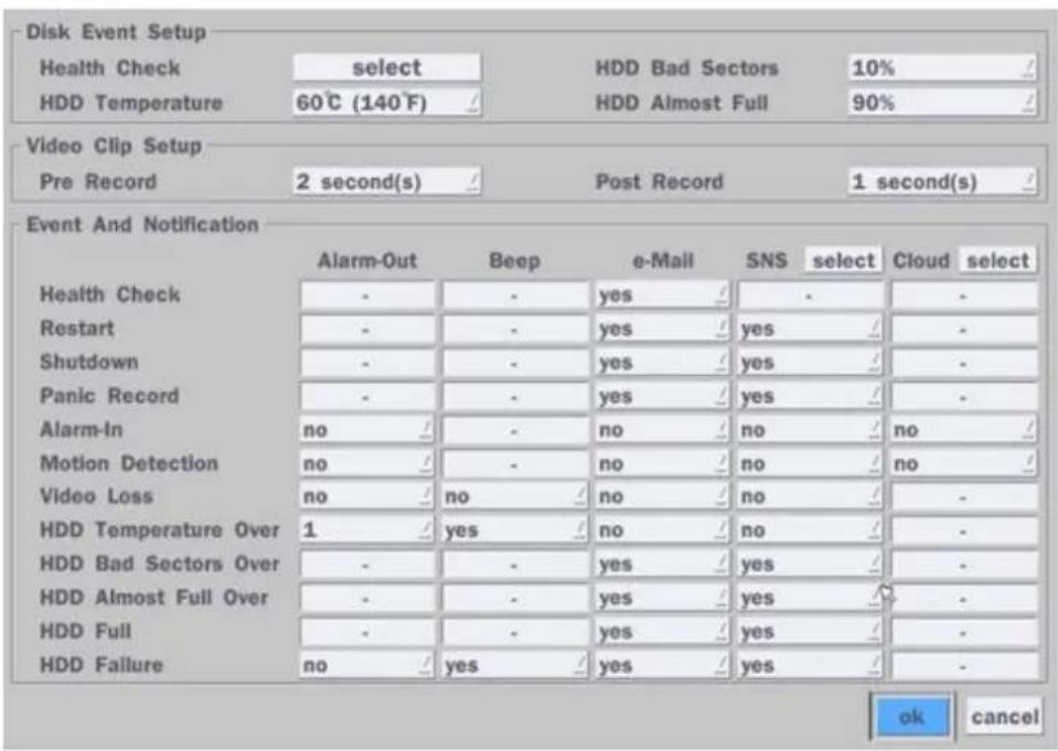
Disk Event Setup Health Check select HDD Bad Sectors 10% / HDD Temperature 60°C (140°F) HDD Almost Full 90% / Video Clip Setup Pre Record 2 second(s) Post Record 1 second(s) / Event And Notification Alarm-Out Beep e-Mail SNS select Cloud select Health Check - - yes / - - - Restart - - yes / yes / - - Shutdown - - yes / yes / - - Panic Record - - yes / yes / - - Alarm-In no / - no / no / no / - Motion Detection no / - no / no / no / - Video Loss no / no / no / no / - HDD Temperature Over 1 / yes / no / no / - HDD Bad Sectors Over - - yes / yes / - - HDD Almost Full Over - - yes / yes / - - HDD Full - - yes / yes / - - HDD Failure no / yes / yes / yes / - ok cancelHealth Check
(Allows the user to set e-Mail Status periodically) : Daily or Weekly or Monthly

text_image
Period daily first / sun / 0 h / ok cancelVideo Clip Setup: Setup the duration of video clip for Pre Record and Post Record.
Event And Notification – Yes or No
(Allows the user to set Event Notification On or Off)
Health Check / Restart / Shutdown / Panic Record
- Enable Email Notification in the event a problem occurs with the VT.
Alarm-In – Enable Email Notification when the camera detects sensor.
Motion Detection – Enable Email Notification when the camera detects motion.
Video Loss – Enable Email, Beep and Alarm output Notification when the camera signal is lost.
HDD Temperature Over – Enable Email, Beep and Alarm output Notification when the HDD temperature.
HDD Bad Sectors Over – Enable Email Notification when the HDD has bad Sectors.
HDD Almost Full Over – Enable Email Notification when the HDD is almost full
HDD Full – Enable Email Notification when the HDD is full
HDD Failure – Enable Email, Beep and Alarm output Notification when the HDD fails.
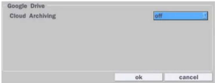
4-2-1. How to use 'Cloud'
- Notice : User have to have a 'Google Drive' Account
- Save video clip on the Google Drive and playback though Mobile device.
1) How to set (Setup - System - System Event Notification - Cloud)
1-1) Click Icon
1-2) Enter Google Drive Account
text_image
Google Drive Cloud Archiving off ok cancel1-3) Video clip will be save at Google Drive when 'Alarm-In' and 'Motion' triggered.
1-4) Set Video clip duration
text_image
Disk Event Setup Health Check select HDD Bad Sectors 10% / HDD Temperature 60°C (140°F) HDD Almost Full 90% / Video Clip Setup Pre Record 2 second(s) Post Record 1 second(s) / Event And Notification Alarm-Out Beep e-Mail SNS select Cloud select Health Check - - yes - - - - Restart - - yes - yes - - - Shutdown - - yes - yes - - - Panic Record - - yes - yes - - - Alarm-in no - - no - no - no - Motion Detection no - - no - no - no - Video Loss no - no - no - no - - HDD Temperature Over 1 - yes - no - no - - HDD Bad Sectors Over - - yes - yes - - - HDD Almost Full Over - - yes - yes - - - HDD Full - - yes - yes - - - HDD Failure no - yes - yes - yes - - ok cancel2) How to playback
2-1) Playback through PC
: Log in Google Drive and select a file and playback
2-2) Playback through Mobile device
: Use 'SpecoPlayer'
Notice – Support iOS from '1.5.8_150316', Android from '3.2.2.7_150316'
4-3. Setup - Record Mode
In the Setup menu, select the Record tab. Then, the Record menu is displayed as pictured below. Navigate through the menu items or change the settings using the mouse or the remote control.

text_image
Record Site ch 1 select Resolution 1920 x 1080 / Frame Rate 15 fps / Quality level 5(H) / Recording Mode continuous / select Sensor Recording - / - / - / - Pre Record 1 minute(s) / Post Record 10 second(s) / Audio off / Schedule select apply cancelFigure 4.3.1. Record Setup Screen
Table 4.3.1. Menu Items in Record Setup Screen
| Menu Item | Description |
| Site | Select a channel for applying the following settings using a mouse or a remote control. Select the “select” button beside of channel button to change the values of all channels. |
| Resolution | Select 1920x1080, 1920x540, 1280x720 and 640x360 using a mouse or a remote control. |
| Frame Rate | Set the frame rate for the specified channel. The sum of the frame rate values per channel cannot exceed the maximum frame rates for a specific recording resolution. |
| Quality | Select the recording quality for the selected channel. Options are;Level 1 (Low), Level 2, Level 3, Level 4, and Level 5 (High) |
| Recording Mode | Assign the recording mode for the selected channel. Options are: Continuous, Motion, Sensor, Schedule, Disable and Smart Recording (c + m : continuous & motion, c + s : continuous & sensor)When Motion Recording is selected, Continuous + Motion recording option can be used. |
 | |
| Sensor Recording | Select the sensor setting for the selected channel. |
| Pre Record | Enable/disable pre-event recording. Pre-event recording time is up to 20 minutes. |
| Post Record | Set the post event recording time duration for the specified channel.(10~60 seconds) |
| Audio | Enable/disable audio recording for the specified channel. |
| Schedule | Set the recording schedule. |
4-3-1. Recording Schedules
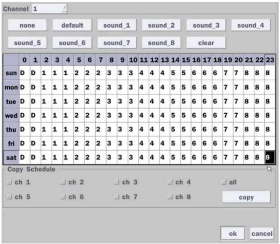
To setup a recording schedule, select Schedule in the Record menu. Navigate through the menu items or change the settings using the mouse or the remote control. Select the Channel; select one of the recording settings: None, Continuous or Motion, then highlight the area for the selected setting. To copy a schedule to a different channel, select the channel from the Copy Schedule menu, then click the Copy button.

text_image
Channel 1 none continuous motion sense clear 0 1 2 3 4 5 6 7 8 9 10 11 12 13 14 15 16 17 18 19 20 21 22 23 sun mon tue wed thu fri sat Copy Schedule □ ch 1 □ ch 2 □ ch 3 □ ch 4 □ all □ ch 5 □ ch 6 □ ch 7 □ ch 8 copy ok CancelFigure 4.3.2. Schedule Recording Setup Screen
- none: Disable recording
• continuous: Continuous recording (Highlighted in Green)
• motion: Motion recording (Highlighted in Yellow) - sensor: Sensor recording (Highlighted in Red)
4-4. Setup - Device Mode
In the Setup menu, select the Device tab. Then, the device menu is displayed as pictured below. Navigate through the menu items or change the settings using the mouse or the remote control.

text_image
Device Alarm Out select Digital Deterrent select Controller & PTZ select Spot Out select Site ch 1 / Motion Zone partial zone / select Motion Sensitivity 5 / Key Tone off / Remote Controller ID 0 / Sensor 1 / Type off / Software Trigger select apply cancelFigure 4.4.1. Device Setup Screen
Table 4.4.1. Menu Items in Device Setup Screen
| Item | Description |
| Alarm Out/ Alarm Duration | Set the sensor, motion, and video loss for triggering alarm relay HDD Error and Video Loss can trigger beeping  |
| Digital Deterrent | Setup schedule and audio recordings for Digital Deterrent. |
| Controller & PTZ | Set the PTZ baud rate, protocol, and ID. |
| Spot-Out | CVBS Out is can be used as Composite Video Output or Spot-Out depending on the Sub Monitor Out of Display setup menu. (Spot-On Event on/off, Spot Event Dwell Time, Sequence On/off, Sequence Dwell Time, Spot Channel) *The last image will keep on the screen until the next event occurred. |
| Site | Select specified channel for motion zone setup. |
| Motion Zone | Select either Full Zone or Partial Zone for motion detection. Press the right button of mouse to exit from Motion Zone grid screen. |
| Motion Sensitivity | Set the motion sensitivity for the selected channel. Control the motion sensitivity from 1 to 9. (1 - Lowest sensitivity, 9 - Highest sensitivity) |
| Key Tone | Enable/disable key tone. |
| Remote Controller ID | Set the remote control ID.1. Select ID.2. Input the remote control ID number. (0 is all)3. An icon will indicate on the Live Screen if the remote control ID is synchronized. The options are from 0 to 99 |
| Sensor | Select the type of each sensor.Option is Off, Normal Open or Normal Close. |
| Software Triger | Remote trigger channels. User can set the channels that want to make a sensor recording through remotely with Software record mode. |
4-4-1. Digital Deterrent
Trigger audio message via motion detection or sensor.

text_image
Import From USB select Export To USB select Record select Schedule select okFigure 4.4.2. Digital Deterrent setup screen
Table 4.4.2. Item for Digital Deterrent Setup Screen
| Item | Description |
| Import From USB | Import up to 8 sound files from USB. |
| Export To USB | Export the sound file to USB |
| Record | Select a channel and set up the date and the duration.And, select the sound file to play. |
Schedule

text_image
Channel ch 1 From 5 / 16 / 2016 / 0 : 58 : 22 / To 05/16/2016 00:58:32 Duration 10 second(s) File Name sound_1 start closeSchedule the sound file considering the expected situation.
text_image
Channel 1 none default sound_1 sound_2 sound_3 sound_4 sound_5 sound_6 sound_7 sound_8 clear 0 1 2 3 4 5 6 7 8 9 10 11 12 13 14 15 16 17 18 19 20 21 22 23 sun D D 1 1 1 2 2 2 3 3 3 4 4 4 5 5 6 6 6 7 7 8 8 8 mon D D 1 1 1 2 2 2 3 3 3 4 4 4 5 5 6 6 6 7 7 8 8 8 tue D D 1 1 1 2 2 2 3 3 3 4 4 4 5 5 6 6 6 7 7 8 8 8 wed D D 1 1 1 2 2 2 3 3 3 4 4 4 5 5 6 6 6 7 7 8 8 8 thu D D 1 1 1 2 2 2 3 3 3 4 4 4 5 5 6 6 6 7 7 8 8 8 fri D D 1 1 1 2 2 2 3 3 3 4 4 4 5 5 6 6 6 7 7 8 8 8 sat D D 1 1 1 2 2 2 34-4-2. Keyboard Controller & PTZ Setup
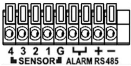
To control the PTZ functions of the camera, connect the PTZ controller to the RS-485 port on the back of the chassis with CAT5 (or equivalent) cable.
① Connect the RS-485 cables of PTZ camera to the RS-485 port on the rear panel.
text_image
4 3 2 1 G + - ■ SENSOR ■ ALARM RS485Figure 4.4.3. Device Mode Setup Screen

text_image
Device Alarm Out select Digital Deterrent select Controller & PTZ select Spot Out select Site ch 1 Motion Zone partial zone select Motion Sensitivity 5 / Key Tone off / Remote Controller ID 0 / Sensor 1 / Type off / Software Trigger select apply cancelFigure 4.4.4. Device Mode Setup Screen
② Open the PTZ sub menu by selecting the submenu button.
text_image
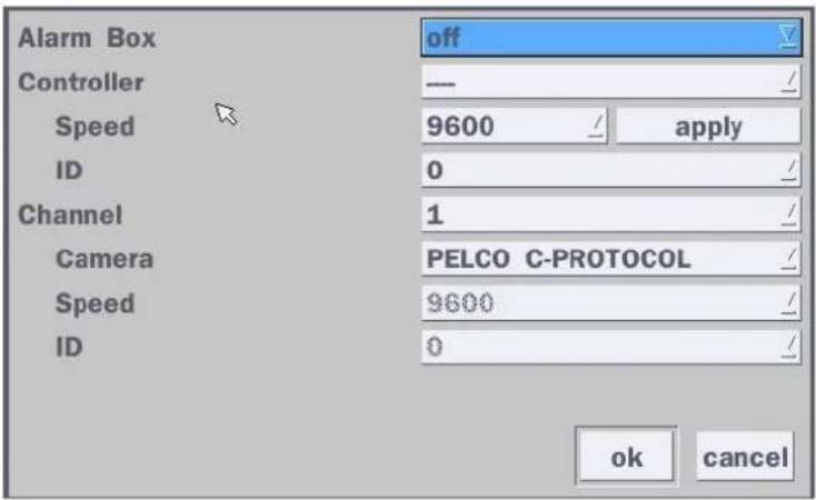
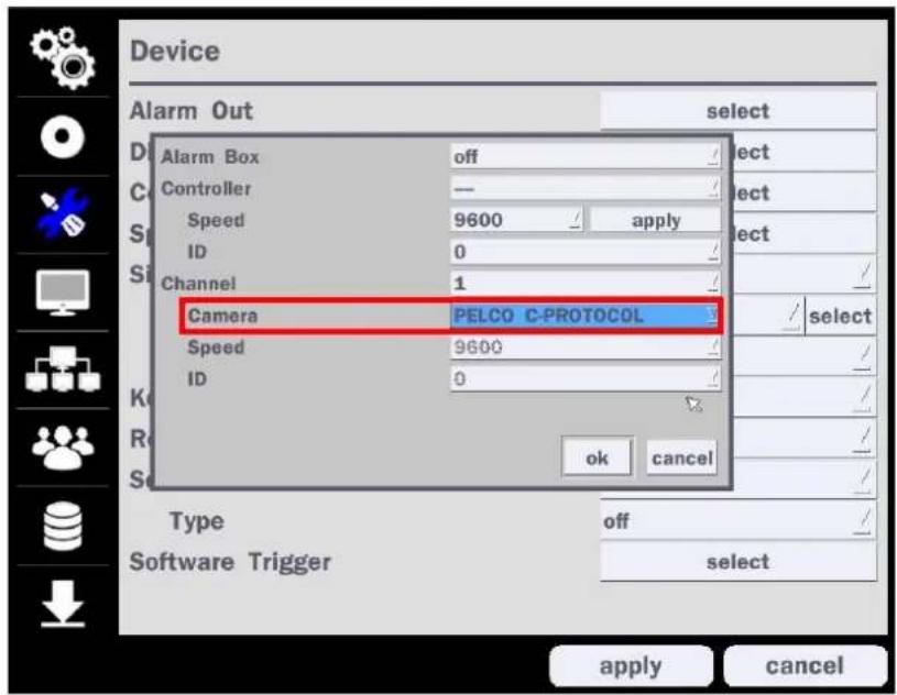
Alarm Box Controller Speed ID Channel Camera Speed ID off —— 9600 / apply 0 1 PELCO C-PROTOCOL 9600 0 ok cancelFigure 4.4.5. PTZ Control Setup Screen
Note: Connect PTZ cameras that support RS-485 directly to the RS-485 port. If the camera is controlled through an RS-232C interface, use an RS-232C to RS-485 to RS-232C signal converter.
Use the PTZ setup screen to select the following options for the camera PTZ controller:
- Channel: Channel connected to a PTZ device
- Camera: Protocol Type
- Speed: 19200, 14400, 9600, 4800, 2400 (Baud rate)
- ID: 0-63
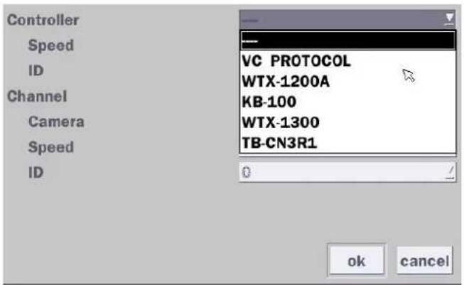
Controller (Keyboard Controller): If a PTZ controller is used, select a controller protocol from Controller menu. Set Speed (Baud Rate) and ID number.
text_image
Controller Speed ID Channel Camera Speed ID VC PROTOCOL WTX-1200A KB-100 WTX-1300 TB-CN3R1 OK cancelFigure 4.4.6. Controller Selection Screen
◆Notice : DxxVT series can use UTC feature.
: UTC(Up The Coax) allows for control of the camera's OSD menu via the coax cable.
User does not need extra connection via RS-485 to control the camera's OSD menu
- How to set (Setup > Device > PTZ & Controller > PELCO C-PROTOCOL)
text_image
Device Alarm Out select Alarm Box off Controller — Speed 9600 apply ID 0 Channel 1 Camera PELCO C-PROTOCOL Speed 9600 ID 0 OK Cancel Type off Software Trigger select apply cancel4-4-3. Spot Out
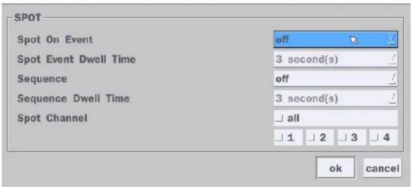
text_image
SPOT Spot On Event off Spot Event Dwell Time 3 second(s) Sequence off Sequence Dwell Time 3 second(s) Spot Channel all 1 2 3 4 ok cancelFigure 4.4.7. Spot-Out Setup Screen
Table 4.4.3. Menu Item in Spot-Out Setup Screen
| Item | Description |
| Spot Out | Only 1 Spot Out is available to use. |
| Spot Type | Spot 1 supports only Full type. (1 channel only) |
| Spot On Event | Enable/disable channel change if an event occurs on a channel. |
| Spot Event | Set the dwell time for the display of the event activated channel. |
| Dwell Time | (3-10 sec) |
| Sequence | Enable/disable sequential display of spot channel in full screen.If select “on”, the selected channel will be displayed on the monitor periodically. |
| Sequence Dwell Time | Set the dwell time for the spot channel display.(3-10 sec) |
| Spot Channel | Select a channel for spot monitoring using the mouse or the remote control and press “ok” button. |
4-4-4. Motion Zone Setup
Select Motion Zone using the mouse or the remote control and select either Partial Zone or Full Zone using the mouse control. The default value is Full Zone.
If Full Zone is selected, the motion zone grid screen is not displayed. Only set the level of sensitivity for Motion Sensitivity.
Full Zone: The motion sensor is active on the whole screen.
Partial Zone: The motion sensor is active in the set detection frame.
Select the motion detection position using the mouse or the remote control. Then left click on the mouse or left click and drag the mouse pointer to select or deselect the area. Highlighted area indicates the partial motion detection zone. Press the "ESC" button or right click on the mouse to return to the previous menu.

natural_image
Interior view of a modern office or lab space with wooden flooring, glass display cases, and ceiling lighting (no visible text or symbols)Figure 4.4.8. Motion Zone Grid Screen
4-5. Setup - Display Mode
In the Setup menu, select the Display tab. Then, the Display menu is displayed as pictured below. Navigate through the menu items or change the settings using the mouse or the remote control. To return to the previous setup menu screen, press the "ESC" button on front panel or select the other menu tab with mouse.

text_image
Display OSD select OSD Contrast 100 Main Monitor Sequence on select Sequence-Dwell Time 3 second(s) Site ch 1 Name CH1 DISPLAY Covert off Color Tuning select Video Output (HDMI) 1920 x 1080 Sub Monitor Output cvbs apply cancelFigure 4.5.1. Display Setup Screen
Table 4.5.1. Menu Items in Display Setup Screen
| Item | Description | |
| OSD | Enable/Disable displaying Channel Name/ Video Loss/ Status Bar & Icon/ Camera Type and Record Mode | |
| Channel NameVideo LossStatus Bar / IconCamera TypeRecord Mode |  | |
| OSD Contrast | Set the visibility level of the On Screen Display (OSD) (50~100) | |
| Main MonitorSequence | Enable/disable sequential display of video in full screen mode. | |
| Sequence-DwellTime | Set the dwell time of each,Single channel display time in sequence mode (3~60 seconds) | |
| Site | Select a channel to apply the name and covert settings change using the mouse or the remote control.Select a channel to apply the following settings using the mouse. | |
| Name | Set the channel name. Press the mouse button and set the channel name on the virtual keyboard. Press “Enter” key when finished its naming. The name can be made up to 36 characters. | |
| Covert | Enable/disable display of the specified video channel in live display. | |
| Color Tuning | Control the Brightness, Contrast, Hue and Saturation. | |
| Video Output (HDMI) | Select video output resolutionSupport 1920 X 1080, 1600x1200, 1280x1024, 1280 X 720 | |
| Sub Monitor Output | Select Sub Monitor Video out through BNC port.CVBS or Spot | |
4-6. Setup - Network Mode
Select the Network tab. Then, the network menu is displayed as pictured below. Navigate through the menu items or change the settings using the mouse or the remote control.

text_image
Network Network Type IP Subnet Mask Gateway DNS (Primary) DNS (Secondary) DDNS Network Video Port Network Audio Port Web Port Network Stream Wireless LAN Push Event dhcp 172.16.2.17 255.255.0.0 172.16.1.254 168.126.63.1 168.126.63.2 select 5445 5446 80 443 select off select select apply cancelFigure 4.6.1. Network Setup Screen
Table 4.6.1. Menu Items in Network Setup Screen
| Item | Description | |
| Network Type | DHCP: DVR will automatically retrieve an IP address. | |
| Static: Network information must be manually configured. | ||
| IP Address | Enter IP address that is assigned for the DVR | |
| Subnet Mask | Enter Subnet Mask that is assigned for the DVR | |
| Gateway | Enter Gateway that is assigned for the DVR. | |
| DNS (Primary) | Enter Primary DNS address that is assigned for the DVR | |
| DNS (Secondary) | Enter Secondary DNS address that is assigned for the DVR | |
| DDNS | Dynamic Domain Name System (DDNS) allows a DNS name to be constantly synchronized with a dynamic IP address. In other words, it allows using a dynamic IP address to be associated with a static domain name so others can connect to it by the static name. Enable/disable using domain name address through DDNS server. | |
| Network Video Port | Enter the port number, (Default: 5445) | |
| Network Audio Port | Display the network audio port (Network Port + 1). | |
| Web Port | Enter the port number for connection using web. (Default: 80) | |
| Network Stream | Set the value for network streaming. | |
| Wireless LAN | 1. Connect USB WIFI Dongle to USB connector on DVR.2. Load the application on your smart phone or PC and enter the WIFI IP Address.3. Find the WIFI SSID and enter the password. (Image is below.)4. Then, the remote viewing and configuration can be used.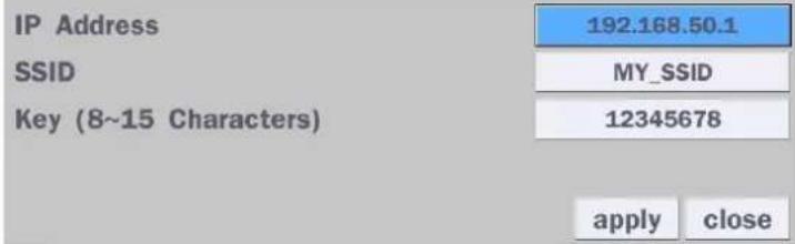 * There is a distance limitation for the Wireless LAN. * There is a distance limitation for the Wireless LAN. | |
| Push Event | Set Phone ID and check Notification function to receive an event message from DVR. | |
4-6-1. Network Types
4-6-1-1. DHCP
An IP address is automatically assigned by the DHCP server, which automatically assigns the IP address and other parameters to new devices.
4-6-1-2. Static
IP address, Subnet Mask, Gateway, and DNS are manually assigned by the user.
• IP Address: The fixed IP address of the DVR unit.
- Subnet Mask: The subnet mask for the LAN.
• Gateway: The IP address of the Gateway.
• DNS (Primary) The primary address of Domain Name Server
• DNS (Secondary): The secondary address of Domain Name Server

NOTE
Unless DNS is properly set, the DDNS and the e-mail features will not work.
4-6-2. DDNS
DDNS (Dynamic Domain Name System) allows a DNS name to be constantly synchronized with a dynamic IP address. It allows using a dynamic IP address to be associated with a static domain name.
Once the setting is completed, the DDNS address will be:
http://hostname.ddns.specoddns.net
For example, if you enter the host name as "D4VT", then the address will be:
http://d4VT.ddns.specoddns.net
Select Network > DDNS. The menu displays as below.
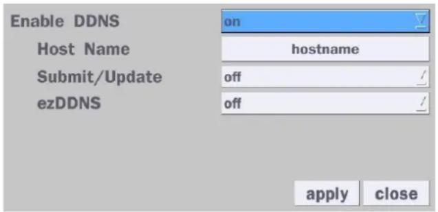
text_image
Enable DDNS Host Name Submit/Update ezDDNS on hostname off off apply closeFigure 4.6.2. Network Setup Screen – DDNS
Table 4.6.2. DDNS
| Item | Description |
| Enable DDNS | Enable/disable the Dynamic Domain Name Service. |
| Host Name | This item allows the user to setup a domain name manually using virtual keyboard displays as shown. |
| Subnet/Update | When manual host name input is done, move the cursor to this item and select ON to submit the settings. |
| ezDDNS | Enable/disable ezDDNS to register the host name automatically. |
4-6-3. Network Port and Web Port
Connecting DVR/DVRs through an IP sharing device, each DVR must be assigned a unique TCP port number for access from outside the LAN. This port number is displayed on Network > Network Port Setup Menu.

NOTE
If you access the DVR only within the same LAN, the TCP port number does not need to be changed.
Network access beyond a router
To access DVR beyond a router (firewall), you must open the proper TCP ports for live/playback streaming,
for commands, for remote backup, and for audio streaming. If these ports are not opened properly, you can't access the DVR beyond a router.

- For live/playback streaming, for commands, for remote backup: Open the port number on Network > Network Video Port menu. The default port number is 5445.
- For bi-directional audio: Open the port number on Network Audio Port. The default port number is [Network Video Port number + 1].
- For web-viewer downloading and remote firmware upgrading: Open the port number on Network > Web Port menu. The default port number is 80.
4-6-4. Network Stream
User can set the Resolution, Frame Rate, and the Quality for the network stream.
- D4VT: Up to 60 fps @ 640x360 and 320x180 for 4 channels.
- D8VT: Up to 120 fps @ 640x360 and 320x180 for 8 channels.
- D16VT: Up to 240 fps @ 640x360 and 320x180 for 16 channels.
| Net Resolution | Frame Rate | Net Quality | |
| All | 640x360 | 15 fps | level 5(H) |
| 1 | 640x360 | 15 fps | level 5(H) |
| 2 | 640x360 | 15 fps | level 5(H) |
| 3 | 640x360 | 15 fps | level 5(H) |
| 4 | 640x360 | 15 fps | level 5(H) |
| okcancel | |||
Figure 4.6.4. Network Setup Screen – Network Stream
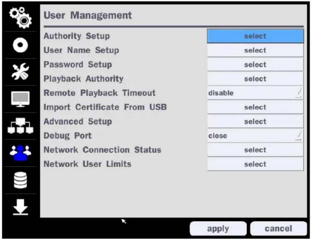
4-7. Setup - User Management Mode
In the Setup menu, select the User Management tab. Then, the User Management menu is displayed as pictured below. Navigate through the menu items or change the settings using the mouse or the remote control.
text_image
User Management Authority Setup select User Name Setup select Password Setup select Playback Authority select Remote Playback Timeout disable / Import Certificate From USB select Advanced Setup select Debug Port close / Network Connection Status select Network User Limits select apply cancelFigure 4.7.1. User Management Setup Screen
Table 4.7.1. Menu Items in User Management Setup Screen
| Item | Description |
| Authority | Only the Admin will have access to the menu. |
| Setup | Password Check: Select the Checkbox to enable the functions or leave the Checkbox blank to disable the functions. Setup: Enable/Disable of access to SetupPB: Enable/Disable of access to PlaybackPTZ: Enable/Disable of access to PTZ ControlRec Off: Enable/Disable of manual RecordNetwork: Enable/Disable of access to Network |
| Selected Checkbox: The DVR will ask for a password when the given function is selected for all users. Blank Checkbox: The DVR will not ask for a password when the given function is selected for all users. |
| Password | Setup | PB | PTZ | Rec Off | Network | |
| Password Check | ✓ | ✓ | ✓ | ✓ | ✓ | |
| ADMIN | ✓ | ✓ | ✓ | ✓ | ✓ | |
| USER1 | 1111 | ✓ | ✓ | ✓ | ✓ | ✓ |
| USER2 | 1111 | ✓ | ✓ | ✓ | ✓ | ✓ |
| USER3 | 1111 | ✓ | ✓ | ✓ | ✓ | ✓ |
| USER4 | 1111 | ✓ | ✓ | ✓ | ✓ | ✓ |
| USER5 | 1111 | ✓ | ✓ | ✓ | ✓ | ✓ |
| USER6 | 1111 | ✓ | ✓ | ✓ | ✓ | ✓ |
| USER7 | 1111 | ✓ | ✓ | ✓ | ✓ | ✓ |
| USER8 | 1111 | ✓ | ✓ | ✓ | ✓ | ✓ |
| USER9 D. | 1111 | ✓ | ✓ | ✓ | ✓ | ✓ |
| ok cancel | ||||||
ADMIN, USER1, USER2, USER3, USER4, USER5, USER6, USER7, USER8, USER9:
Selected Checkbox: The user can access the function.
Blank Checkbox: The user can not access the function.
User Name Setup
Change the name of USER1, USER2, USER3, USER4, USER5, USER6, USER7, USER8, and USER9. Click "select" and change the user name on the virtual keyboard.

text_image
User ID USER1 select ok cancelPassword Setup
Options are ADMIN, USER1, USER2, USER3, USER4, USER5, USER6, USER7, USER8, and USER9:

Select User Password using the mouse or the remote control. Select "User ID" and enter the current password. And enter a new password and enter the same password again to confirm and select "ok". Then the message "Password Changed" is displayed. The factory default password of USER1 \~ 9 is 1111.
It is highly recommended to assign a new password to protect the system.
Playback Authority
Set authority level of playback on each user.
Checked box: authorized to playback. Blank check box: no authority.
| 1 | 2 | 3 | 4 | 5 | 6 | 7 | 8 | |
| ADMIN | ✘ | ✘ | ✘ | ✘ | ✘ | ✘ | ✘ | ✘ |
| USER1 | ✓ | ✘ | ✘ | ✘ | ✘ | ✘ | ✘ | ✘ |
| USER2 | ✘ | ✘ | ✘ | ✘ | ✘ | ✘ | ✘ | ✘ |
| USER3 | ✘ | ✘ | ✘ | ✘ | ✘ | ✘ | ✘ | ✘ |
| USER4 | ✘ | ✘ | ✘ | ✘ | ✘ | ✘ | ✘ | ✘ |
| USER5 | ✘ | ✘ | ✘ | ✘ | ✘ | ✘ | ✘ | ✘ |
| USER6 | ✘ | ✘ | ✘ | ✘ | ✘ | ✘ | ✘ | ✘ |
| USER7 | ✘ | ✘ | ✘ | ✘ | ✘ | ✘ | ✘ | ✘ |
| USER8 | ✘ | ✘ | ✘ | ✘ | ✘ | ✘ | ✘ | ✘ |
| USER9 | ✘ | ✘ | ✘ | ✘ | ✘ | ✘ | ✘ | ✘ |
| Remote Playback Timeout | Disconnect the remote playback after the specific time (Disable, 5min, 10min, 15min, 30min, 60min. |
| Import Certificate From USB | Upload https certificate through USB |
| Advanced Setup | Send IP address and ports information to the control center |
| Debug Port | Open or Close the ports for remote checking |
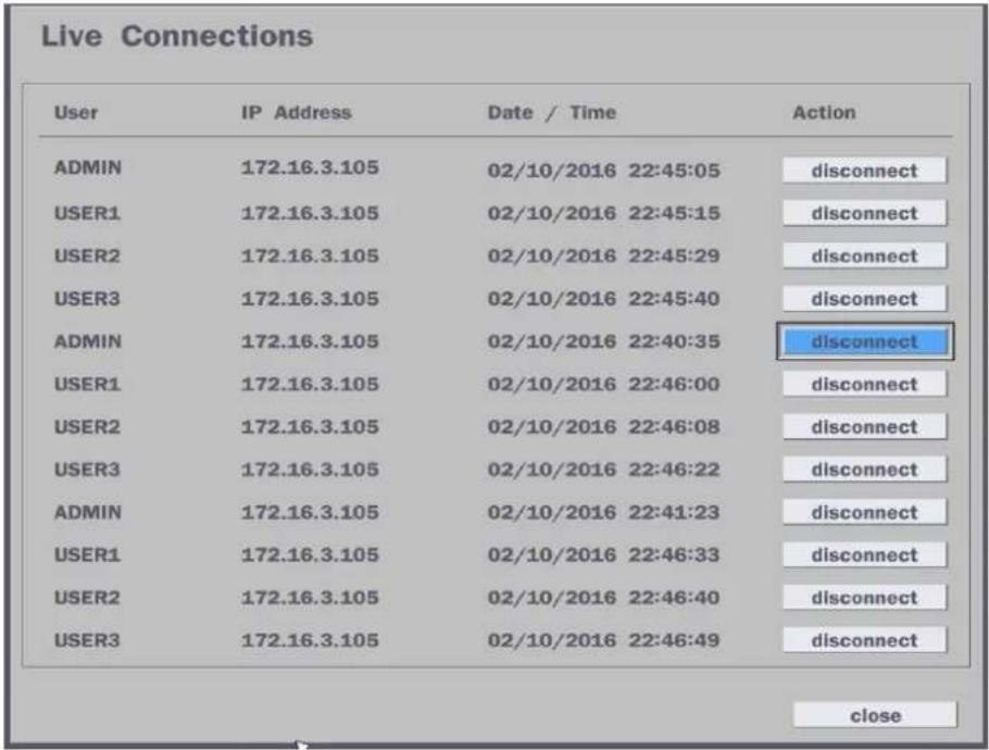
| Network Connection Status | Shows the current network connection status (User, IP Address, Date/Time). And do disconnect the user's network connection to click 'disconnect' button. |
 | |
| Network User Limits | User can select network access user number (4 users of 12 users). DVR system will be restarted if user change this network user number. |
 |
4-8. Setup - Storage Mode
In the Setup menu, select the Storage tab. Then, the Storage menu is displayed as pictured below. Navigate through the menu items or change the settings using the mouse or the remote control.

text_image
Storage Overwrite on Disk Format select Disk Info select Recording Limit on Recording Limit Days 30 day(s) apply cancelFigure 4.8.1. Storage Setup Screen
Table 4.8.1. Menu Items in Storage Setup Screen
| Item | Description | |||
| Overwrite | When enabled, the DVR will continue recording and overwrite the oldest existing recorded data once the hard drive is full. When disabled, recording will stop once the hard drive is full. | |||
| Disk Format | User will have an option for formatting the Hard Drive.After formatting HDD, the DVR will reboot. | |||
 | Caution: It is recommended to archive any data that you may need in the future before formatting the hard drive. | |||
| WARNINGAre you sure to format the HDD?If YES, the system will restart to format the HDD.Please wait a few seconds.If NO, the data will be kept. | ||||
| Disk Info | Hard drive information.Displays the following information: | |||
| HDD Size : 1740 GB (Free : 722 GB)HDD Last Time : 05/25/2016 17:22:00 | ||||
| Model Name | Temperature | Health(Good/Normal/Bad) | ||
| HDD 1 | WDC WD20PURX-64P6ZY0 | 39 °C (102 °F) | Good | |
| HDD 2 | ||||
| Recording Limit | Enable recording limit: The amount of data recorded in HDD will be limited to the most recent number of days as set by “Recording Limit Days”.Disable recording limit: When Overwrite is on, DVR will continue to record when HDD is full and overwrite older data. When Overwrite is off, DVR will stop recording when the HDD is full. | |||
| Recording LimitDays | Set the recording limit days. (1- 90 days)If the Recording Limit Days are set to 1, the data will be overwritten after 24 hours. | |||
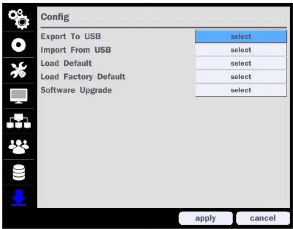
4-9. Setup - Config Mode
In the Setup menu, select the Config tab. Then, the configuration menu is displayed as pictured below. Navigate through the menu items or change the settings using the mouse or the remote control.
text_image
Config Export To USB Import From USB Load Default Load Factory Default Software Upgrade select select select select select apply cancelFigure 4.9.1. Configuration Setup Screen
Table 4.9.1. Configuration Setup
| Item | Description |
| Export To USB | User can save the current configuration (Setting values) of the DVR to the USB flash drive. Plug in the USB flash on the front panel and press the button to start the saving process. |
| Import From USB | User can upload the configuration of the DVR to another DVR using the USB Flash drive. Plug in the USB flash drive on the front panel and press the button to start the loading process. |
| Load Default | Press the button to reset the system to the default settings.The following settings such as Language, DVR ID, Security User Authentication, Security User P/W, Date Format, DLS settings, Network settings, HDD overwrite, Limit recording, HDD serial number, and HDD ERROR time will not be included. |
| Load Factory Default | Press the button to reset the system to the factory default settings. |
| Software Upgrade | Upgrade software to the latest version.After connecting USB flash drive to USB port on the DVR, click SEARCH.It will automatically find the upgrade file. |
4-9-1. Software Upgrade
- In the USB flash drive root directory, create a new folder named "upgrade"
- Create sub-folder for each model under "upgrade" folder and copy each software file to their folder.
- "d4VT" for D4VT: "main_D4VT_speco_.*.*_201****"
- "d8VT" for D8VT: "main_D8VT_speco_.*.*_201****"
- "d16VT" for D16VT: "main_D16VT_speco_.*.*_201****"
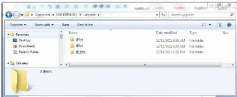
text_image
Computer > USB DRIVE (E:) > upgrade > Organize Share with Burn New folder Favorites Desktop Downloads Recent Places Libraries Name Date modified Type Size d4vs 12/15/2011 8:55 AM File folder d8vs 12/15/2011 8:56 AM File folder d16vs 12/14/2011 1:20 PM File folder 3 items- Plug in the USB flash drive.
- Navigate to Config menu of Setup.
- Select Software Upgrade.
- Follow the procedure from Figure 4.9.2 to Figure 4.9.5.
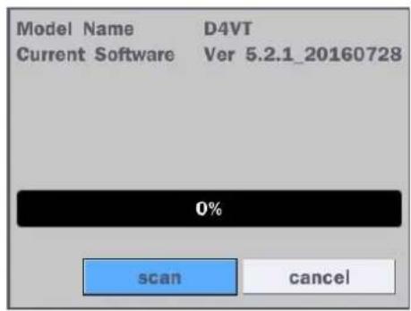
text_image
Model Name D4VT Current Software Ver 5.2.1_20160728 0% scan cancelFigure 4.9.2

text_image
Model Name D4VT Current Software Ver 5.2.1_20160728 USB Check Found USB Mount Ok File Check main_d4vt_speco_5.2.1_20160728.bin 0% upgrade cancelFigure 4.9.3
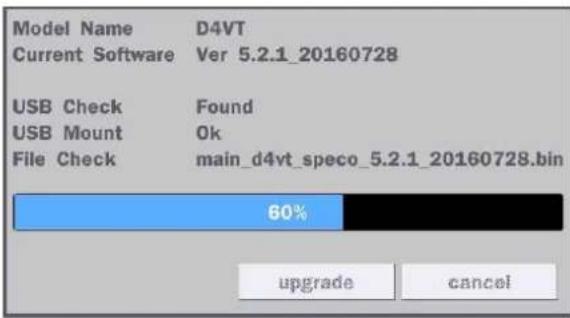
text_image
Model Name D4VT Current Software Ver 5.2.1_20160728 USB Check Found USB Mount Ok File Check main_d4vt_speco_5.2.1_20160728.bin 60% upgrade cancelFigure 4.9.4

text_image
Model Name D4VT Current Software Ver 5.2.1_20160728 USB Check Found USB Mount Ok File Check main_d4vt_speco_5.2.1_20160728.bin 100% Upgrade Success restart nowFigure 4.9.5

NOTICE
If selecting "Restart Now" when the USB flash drive is plugged, the following message will pop up with beep sound.

text_image
WARNING! Please unplug USB drive. ok5. Live, Search and Playback
5-1. Live View
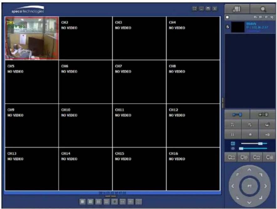
In the Live screen, video inputs from the cameras are displayed as they are configured in the Display Setup screen. When the mouse is right clicked, and the quick operation window will be displayed as below.

text_image
Search Setup Display Snapshot Super EZ Copy Enable Manual Record Instant Playback Advanced Menu EZ Setup Audio Camera PTZ Enable Main Monitor Sequence Disable Alarm Out Manual Digital Deterrent Site Information System Information Export Help System Lock System ShutdownFigure 5.1.1. Live Screen and Quick Operation Window
On the bottom of the screen, various On-Screen Display (OSD) symbols, which indicate the status of the DVR, are described in Table 5.1.1.
Table 5.1.1. Status Indicator Icons in Live Viewing Screen
| Icon | Description |
 | Indicates the DVR is locked. Note) to unlock, right click on the live view screen and select on Unlock. |
 | Audio mute. Audio channel output can be selected from the quick operation menu |
 | Indicates that alarm is set. |
 | Indicates that alarm output is activated. |
 | Event indicator. When there is an event (motion recording, video loss, HDD fail, S.M.A.R.T), this icon will be highlighted. |
 | Indicates that a network client is connected to the DVR. |
 | Indicates that sequencing mode is enabled. |
| 2009/04/14 17:23:40 | Displays the current date and time. |
| RC: ALL | Remote control ID display. If a remote ID is not set, the message “ALL displayed. |
 15% 15% | When Overwrite is not enabled, this displays the percent of the hard disk usage from 0-99%. When Overwrite is enabled, the Bar will indicate with Overwrite |
 | Continuous recording in progress. |
 | Manual recording in progress. To set the Manual recording mode, press the Record button on the front panel. |
 | Motion alarm recording in progress. |
 | Sensor recording in progress. (Only for D8VT and D16VT model.) |
Table 5.1.2. Menu Items in Quick Operation Window
| Icon | Description |
| Search | Select this option to enter the Search menu. |
| Setup | Select this option to enter the Setup menu. |
| Display | Display layout. Select between different multi-view display formats.Available formats: D4VT: 1x1, 2x2D8VT: 1x1, 2x2, 3x3; D16VT: 1x1, 2x2, 3x3, 4x4 |
| Snapshot | Click this option to create a snapshot of selected channel image.(BMP Still Image) |
| Super EZ Copy | Direct Backup of the selected channel to USB flash drive without going through the search mode. |
| Enable Manual Record | Manual Record button. Click this button to enable manual recording. Also known as Panic Record. |
Advanced Menu
| EZ Setup | Select this option to start EZ Setup Wizard |
| Audio | Select this option to set an audio channel to output; (Channel 1 through 4, Audio Mute). |
| Camera PTZ | Select this option and the PTZ user interface will appear. |
| Enabel Main Monitor Sequence | Select this option to enable/disable sequence function. |
| Disable Alarm Out | Click this button to enable/disable Alarm outputs |
| Manual Digital Deterrent | Window where use can manually trigger the digital deterrent audio.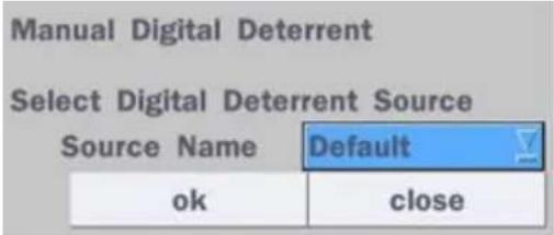 |
| Site Information | Press the button to view the record setting of a selected channel. |
| System Information | Press the button to view the system information.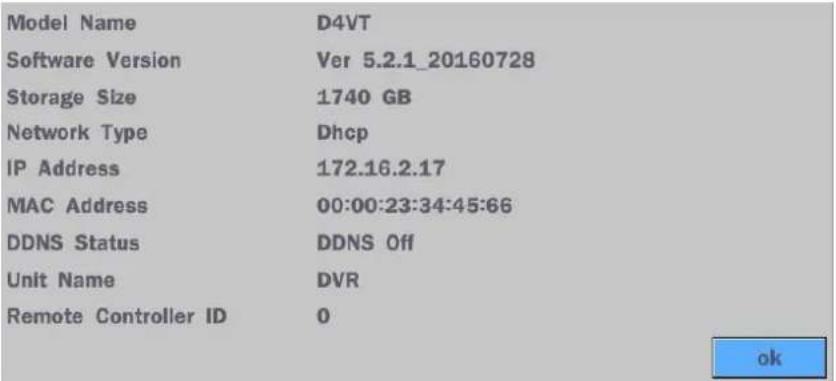 |
| Export Help | Displays window with instructions for exporting video. |
| System Lock | Locks the DVR from user access. |
| System Shutdown | Click this button to shutdown system. |
5-1-1. PTZ Control
Table 5.1.3. Menu Items in PTZ Control Window
| Image | Item | Description | |
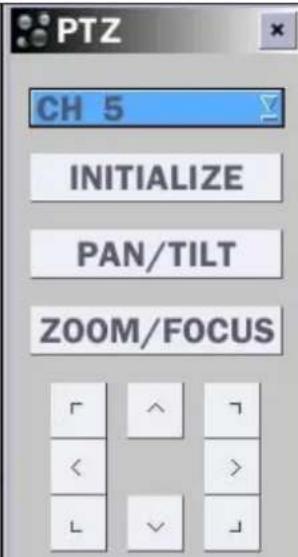 |  | INITIALIZE | Initialize the PTZ settings of the selected camera |
| PAN/TILT | Select PAN/TILT using the ▲▼◀ and ▶button, then press SEL. Adjust the tilt (UP/DOWN)/pan (LEFT/RIGHT) position using the ▲▼◀and ▶buttons. | ||
| ZOOM/FOCUS | Select ZOM/FOCUS using the▲▼◀ and ▶buttons, then press SEL. Adjust the zoom (UP/DOWN)/ focus (LEFT/RIGHT)position using the ▲▼◀ and ▶ buttons. | ||
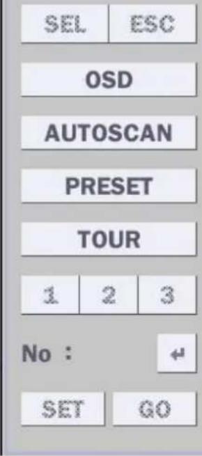
| OSD | Select OSD to enter the menu. Control keys are Right, Left, UP, Down, Select, Far (REW KEY), and Near (FF KEY). Press the ESC button to return to the previous menu. Press the PTZ button to close the OSD menu. | ||
| AUTOSCAN | Press the right key(▶) to start auto scan. Press the left key (◀) to stop auto scan. | ||
| PRESET | Select PRESET, then press the left key(◀). A number input window will appear. Set the number (3digits) using the number key, then press the SEL to confirm the preset number for the current position. Press the right key (▶) and enter the number (3digits) to go to the preset position. | ||
| TOUR | Select TOU and press the right (▶) key. A number input window will open. Select a number (1digit) using a number key, then press SEL to start the tour. Press the left (◀) key to stop the tour.Preset the number of the tour group in the OSD menu. | ||
| NUMBER | For the TOUR and PRESET menu. | ||
 | Press ESC to return to the main menu | ||
5-2. Digital Zoom in Live and Playback Screen
VT series supports Digital Zoom feature during live and playback mode.
- Double click the target channel.

text_image
CH 1 CH 2 CH 5 CH 6- Click the left button of the mouse and drag to make rectangular shape.

natural_image
Two-panel image showing a museum exhibit with a close-up of a display case and a close-up of an ancient artifact, both without readable text or symbols.5-3. Search Screen
To enter the search screen menu, select Search menu on the screen using the mouse or press Search icon on live screen.
text_image
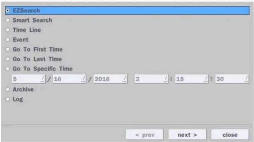
EZSearch Smart Search Time Line Event Go To First Time Go To Last Time Go To Specific Time 5 / 16 / 2016 / 2 : 15 : 30 / Archive Log < prev next > closeFigure 5.3.1. Search Screen
There are 7 options in the Search Menu, they are: EZSearch, Smart Search, Time Line (Calendar), Event, Go To First Time, Go To Last Time, Go To Specific Time, Archive list, and Log list on the screen.
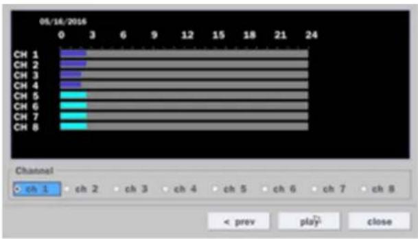
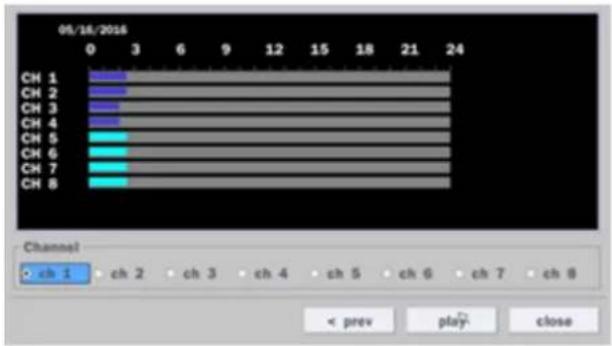
5-3-1. EZSearch
The EZSearch window is used to find stored video with ease using the thumb nail playback screen.
text_image
Sun Mon Tue Wed Thu Fri Sat 1 2 3 4 5 6 7 8 9 10 11 12 13 14 15 16 17 18 19 20 21 22 23 24 25 26 27 28 29 30 31 < next > closeFigure 5.3.2. Calendar Screen
bar
| Channel | Value | |---|---| | CH 1 | 3 | | CH 2 | 3 | | CH 3 | 3 | | CH 4 | 3 | | CH 5 | 3 | | CH 6 | 3 | | CH 7 | 3 | | CH 8 | 3 |Figure 5.3.3. Channel Selection Screen
| 00:00:00 ~ NO DATA | 01:00:00 ~ NO DATA | 02:00:00 ~ NO DATA | 03:00:00 ~ NO DATA | 04:00:00 ~ NO DATA |
| 05:00:00 ~ NO DATA | 05:00:00 ~ NO DATA | 07:00:00 ~ NO DATA | 08:00:00 ~ NO DATA | 09:00:00 ~ NO DATA |
| 10:00:00 ~ NO DATA | 11:00:00 ~ NO DATA | 12:00:00 ~ NO DATA | 13:00:00 ~ NO DATA | 14:00:00 ~ NO DATA |
| 15:00:00 ~ NO DATA | 16:00:00 ~ NO DATA | 17:00:00 ~ NO DATA | 18:00:00 ~ NO DATA | 19:00:00 ~ NO DATA |
| 20:00:00 ~ NO DATA | 21:00:00 ~ NO DATA | 22:00:00 ~ NO DATA | 23:00:00 ~ NO DATA | EXIT |
Step1. 24 Hourly Thumbnail Screen

text_image
07:00:00 ~ 07:02:30 ~ 07:05:00 ~ 07:07:30 ~ 07:10:00 ~ 07:12:30 ~ 07:15:00 ~ 07:18:30 ~ 07:20:00 ~ 07:22:30 ~ NO DATA 07:25:00 ~ NO DATA 07:27:30 ~ NO DATA 07:30:00 ~ NO DATA 07:32:30 ~ NO DATA 07:35:00 ~ NO DATA 07:37:30 ~ NO DATA 07:40:00 ~ NO DATA 07:42:30 ~ NO DATA 07:45:00 ~ NO DATA 07:47:30 ~ NO DATA 07:50:00 ~ NO DATA 07:52:30 ~ NO DATA 07:55:00 ~ NO DATA 07:57:30 ~ NO DATA PREVIOUSStep2. Every 2 minutes and 30 seconds

text_image
07:20:00 07:20:10 07:20:20 07:20:30 07:20:40 07:20:50 07:21:00 07:21:10 07:21:20 07:21:30 07:21:40 07:21:50 07:22:00 07:22:10 07:22:20 PREVIOUSStep3. Every 10 seconds

Step4. Every 1 second
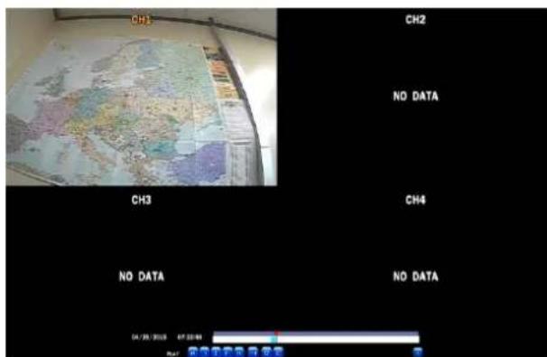
text_image
CH1 CH2 NO DATA CH3 CH4 NO DATA NO DATA 04/29/2018 07:22:00 No 采样手数 有 效备Figure 5.3.4. Second Thumbnail Screen
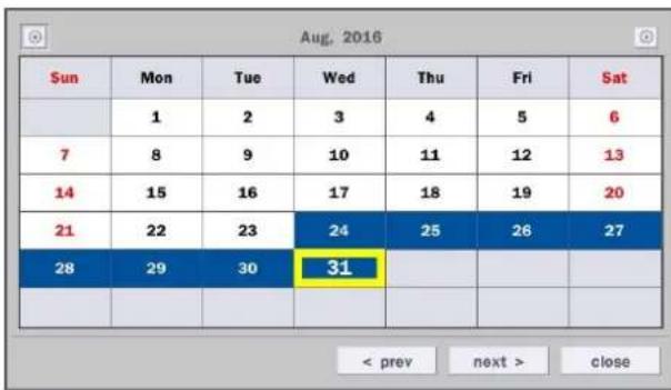
When the EZSearch menu is selected, a calendar is displayed that highlights dates with recorded data.
- Select a specific date on the calendar.
- Select a channel from Channel Selection Screen.
Then the Thumbnail Search screen displays 24 thumbnails, one for each hour of the day.
- Second step shows every 2 minutes and 30 seconds screen.
- Third step shows every 10 seconds.
- Fourth step shows every 1 seconds
- Playback the selected image.
5-3-2. Smart Search
Smart Search is search the selected area quickly. User can search need to know area.

text_image
Aug, 2016 Sun Mon Tue Wed Thu Fri Sat 1 2 3 4 5 6 7 8 9 10 11 12 13 14 15 16 17 18 19 20 21 22 23 24 25 26 27 28 29 30 31 < prev next > closeFigure 5.3.4. Calendar Screen
bar
| Channel | Value | |---|---| | CH 1 | 3 | | CH 2 | 3 | | CH 3 | 3 | | CH 4 | 3 | | CH 5 | 3 | | CH 6 | 3 | | CH 7 | 3 | | CH 8 | 3 |Figure 5.3.5. Channel Selection Screen
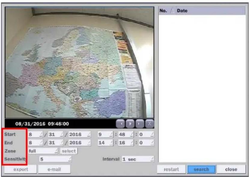
text_image
08/31/2016 09:48:00 Start 8 / 31 / 2016 9 : 48 : 0 End 8 / 31 / 2016 14 : 16 : 0 Zone full select Sensitivity 5 Interval 1 sec export e-mail restart search close No. Date1) Select the start time and End time that user want to search
2) Set Zone as 'Partial' or 'Full'
3) Partial zone can select the area that user want.

text_image
08/31/2016 09:48:00 Start 8 / 31 / 2016 9 : 48 / 0 End 8 / 31 / 2016 14 : 16 / 0 Zone partial select To Exit, Click Right Button. Sensitivity 5 Interval 1 sec export e-mail restart search close No. Date To Exit, Click Right Button. Interval 1 sec4) Click "select" button after selection as 'Partial' then user can drag the area.
5) Click right mouse button when the area selection was finished.
6) Select 'search' then show the detected motion lists at the right blank.
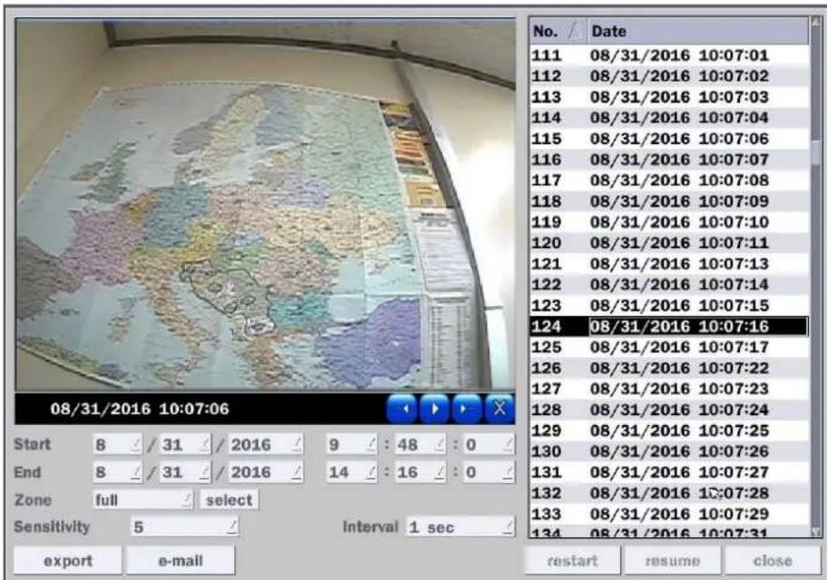
text_image
08/31/2016 10:07:06 Start 8 / 31 / 2016 9 : 48 : 0 End 8 / 31 / 2016 14 : 16 : 0 Zone full select Sensitivity 5 Interval 1 sec export e-mail No. Date 111 08/31/2016 10:07:01 112 08/31/2016 10:07:02 113 08/31/2016 10:07:03 114 08/31/2016 10:07:04 115 08/31/2016 10:07:06 116 08/31/2016 10:07:07 117 08/31/2016 10:07:08 118 08/31/2016 10:07:09 119 08/31/2016 10:07:10 120 08/31/2016 10:07:11 121 08/31/2016 10:07:13 122 08/31/2016 10:07:14 123 08/31/2016 10:07:15 124 08/31/2016 10:07:16 125 08/31/2016 10:07:17 126 08/31/2016 10:07:22 127 08/31/2016 10:07:23 128 08/31/2016 10:07:24 129 08/31/2016 10:07:25 130 08/31/2016 10:07:26 131 08/31/2016 10:07:27 132 08/31/2016 10:07:28 133 08/31/2016 10:07:29 134 08/31/2016 10:07:31 restart resume close7) Click the list that user want to playback.
text_image
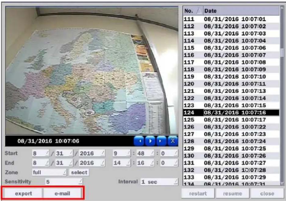
08/31/2016 10:07:06 Start 8 / 31 / 2016 9 : 48 : 0 / End 8 / 31 / 2016 14 : 16 : 0 / Zone full select Sensitivity 5 Interval 1 sec / export e-mail No. Date 111 08/31/2016 10:07:01 112 08/31/2016 10:07:02 113 08/31/2016 10:07:03 114 08/31/2016 10:07:04 115 08/31/2016 10:07:06 116 08/31/2016 10:07:07 117 08/31/2016 10:07:08 118 08/31/2016 10:07:09 119 08/31/2016 10:07:10 120 08/31/2016 10:07:11 121 08/31/2016 10:07:13 122 08/31/2016 10:07:14 123 08/31/2016 10:07:15 124 08/31/2016 10:07:16 125 08/31/2016 10:07:17 126 08/31/2016 10:07:22 127 08/31/2016 10:07:23 128 08/31/2016 10:07:24 129 08/31/2016 10:07:25 130 08/31/2016 10:07:26 131 08/31/2016 10:07:27 132 08/31/2016 10:07:28 133 08/31/2016 10:07:29 134 08/31/2016 10:07:31 restart resume close8) 'export' and 'e-mail' icon will be activate for backup or mail notice
5-3-3. Time Line Search
The Calendar Search window is used to find the stored video by using the time line bar.

text_image
Aug. 2016 Sun Mon Tue Wed Thu Fri Sat 1 2 3 4 5 6 7 8 9 10 11 12 13 14 15 16 17 18 19 20 21 22 23 24 25 26 27 28 29 30 31Figure 5.3.7. Calendar Screen
text_image
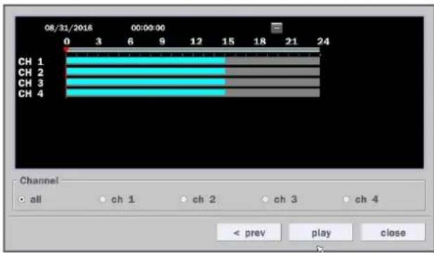
08/31/2016 00:00:00 CH 1 CH 2 CH 3 CH 4 Channel • all • ch 1 • ch 2 • ch 3 • ch 4 < prev play closeFigure 5.3.8. Time-Line Search Screen
When the Timeline menu is selected, the user can see a calendar, which displays recorded dates with highlights. Select a specific date and time. Click and drag the red time indicator bar to the desired hour. User can select a specific minutes using a button in the above red box. Press the "play" button after selecting the specific time. Press the "prev" to return to the Search window.
5-3-4. Event Search
The Event Search window is used to find stored video.

text_image
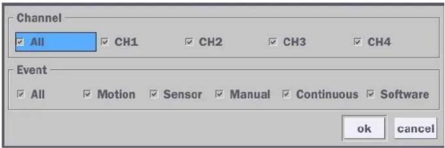
Channel CH1|CH2|CH3|CH4 select Event Motion|Sensor|Manual|Continuous|Software Channel Log Date CH2 Continuous 08/31/2016 00:00:01 CH3 Continuous 08/31/2016 00:00:01 CH4 Continuous 08/31/2016 00:00:01 CH2 Continuous 08/31/2016 01:00:01 CH3 Continuous 08/31/2016 01:00:01 CH4 Continuous 08/31/2016 01:00:01 CH2 Continuous 08/31/2016 02:00:01 230 log(s) found backup < prev play closeFigure 5.3.9. Event Search Screen
When the Event menu is selected, a calendar is displayed that highlights dates with recorded event data. Select a specific date and the event log will be displayed. After selecting the event, Press the "play" button to playback the recorded data or press the "backup" button to export the data. User can find a data of the specific channel and event using a button in the above red box as following Figure 5.3.9. Press the "prev" to return to the Search window.
text_image
Channel ✓ All ✓ CH1 ✓ CH2 ✓ CH3 ✓ CH4 Event ✓ All ✓ Motion ✓ Sensor ✓ Manual ✓ Continuous ✓ Software ok cancelFigure 5.3.10. Event Search Screen
5-3-5. Go To First Time
You can access the oldest recorded data on the DVR hard drive by selecting Go To First Time on the Search window. Press the "prev" to return to the Search window.
5-3-6. Go To Last Time
You can access the latest recorded data on the DVR hard drive by selecting Go To Last Time on the Search window. Press the "prev" to return to the Search window.
5-3-7. Go To Specific Time
User can search for video data from a specific instance by setting the date and time in the GO TO SPECIFIC TIME menu. Use the mouse or the remote control to change the date and time value and press the PLAY button after setting. If there is no video data in the set date and time, No Data Exist message displays.
5-3-8. Archive List
The ARCHIVE Search window is used to find previously stored video or images.

text_image
Log Date LIVE BMP (SPLIT) 08/31/2016 15:05:49 CH2 AVI(0 min) 08/31/2016 15:16:54 LIVE BMP (SPLIT) 08/31/2016 15:29:27 CH2 PLAY BMP 08/31/2016 15:35:47 CH1 NSF(1 min) 08/31/2016 15:40:38 CH1 NSF(0 min) 08/31/2016 15:45:43 6 log(s) found < prev display close Backup LIVE BMP (SPLIT) Media USB 08/31/2016 15:05:47 backup closeFigure 5.3.11. Archive Search Screen
When the Archive menu is selected, the user can see a calendar, which has archive data. Select a specific date and then the archived data will be displayed. Press the Display button to view the still image or the first frame of the selected video, then the user can export the selected data.
5-3-9. Log List
You can access the LOG list search screen by selecting LOG on the SEARCH window.

text_image
Log NTP : Keep(earlier than system time) System Start : [25] Software Upgrade Video In : CH1 Video In : CH2 Video In : CH3 Video In : CH4 NTP : Keep(earlier than system time) Date 08/31/2016 04:00:00 08/31/2016 13:58:33 08/31/2016 13:58:34 08/31/2016 13:58:34 08/31/2016 13:58:34 08/31/2016 13:58:34 08/31/2016 13:59:00 7 log(s) found backup < prev next > closeFigure 5.3.12. Log List Screen
When the Log menu is selected, the user can see a calendar, which has a log data. Select a specific date and press NEXT button, and then the log data will be displayed. Press the SAVE button to save the data and then the data is saved as a text file format.
5-4. Play Mode
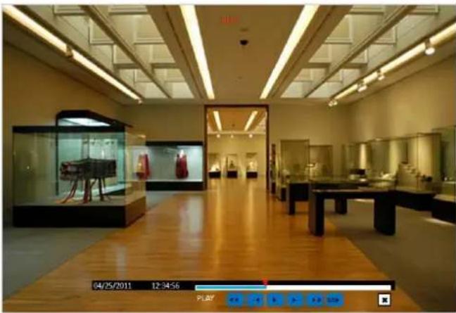
During playback of a recorded event, the mode changes from SEARCH to PLAY. While in PLAY mode, you may return to the SEARCH screen by pressing the X button on the status bar.
natural_image
Interior view of a museum gallery with wooden flooring, display cases, and glass cases (no visible text or signage)Figure 5.4.1. Play Mode Screen
The following status bar hides automatically and appears again if a mouse pointer is positioned to the bottom of the screen.
Table 5.4.1. Button Functions in PLAY Mode
| Button | Description |
 | 1x, 2x, 4x, 8x,16x, 32x speeds for D4VT1x, 2x, 4x, 8x,16x for D8VT1x, 2x, 4x, 8x for D16VTSingle Channel backward playback speed 1x, 2x, 4x, 8x, 16x, 32x, 64x |
 | Jump/Step backward. The playback position moves 60 seconds backward. |
 | Press to play or pause recorded video. |
 | Jump/Step forward. Playback position moves 60 seconds forward. |
 | 2x, 4x, 8x,16x, 32x speeds for D4VT2x, 4x, 8x,16x for D8VT2x, 4x, 8x for D16VTSingle Channel forward playback speed 1x, 2x, 4x, 8x, 16x, 32x, 64x |
 | Slow Mode play. Forward playback speed x1/4, x1/2 |
 | Press to back up the video. User can select archive file formats (Still image, NSF, AVI and EXE). |
 | EZCopy button. User can copy video data as NSF, AVI and EXE format. |
 | Return to the previous menu screen, search window, or exit from the Menu. |
6. Export and Back Up
6-1. Still Image Backup onto USB Flash Drive
Still images can be captured and archived onto a USB flash drive or an USB external hard drive in live mode or while playing back recorded video.
- Select a specific channel, which wants to backup on live screen.
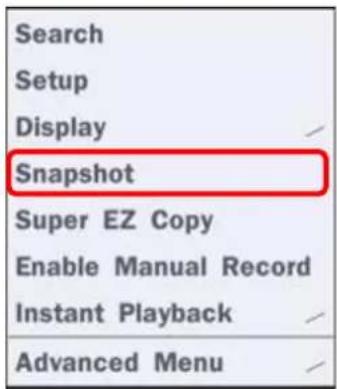
- When you press "Snapshot" button on Quick operation window, the media selection window screen will display.
text_image
Search Setup Display Snapshot Super EZ Copy Enable Manual Record Instant Playback Advanced Menu
text_image
Please Select Media Type • USB Drive < prev start close- Once you press "start" button, the system will capture a still image and archive onto a USB flash drive.

NOTICE
USB Flash Drive must be in FAT32 file format.
6-2. Video Backup onto USB Flash Drive during playback
Video can be captured and archived onto the USB flash drive or a hard drive while playing back the recorded video. In playback mode, press the “Export” button to launch the backup function.
- When you press “Export” button on the selected channel or all channels, the DVR will ask whether to archive a Still Image, NSF, AVI or EXE and select the proper media type.
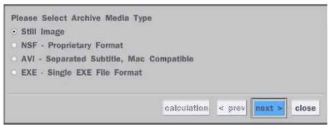
text_image
Please Select Archive Media Type • Still Image • NSF - Proprietary Format • AVI - Separated Subtitle, Mac Compatible • EXE - Single EXE File Format calculation < grav next > close
text_image
Please Select Media Type • USB Drive calculation < prev start close- Select USB Drive (Flash Drive) to back up less than an hour.
Select USB HDD (Large Backup) to back up from 1 hour to 24 hours. (Only for NSF type)
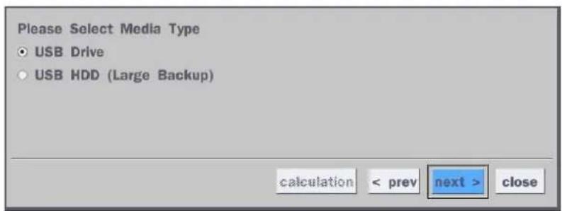
text_image
Please Select Media Type • USB Drive • USB HDD (Large Backup) calculation < prev next > close- Once you select the channel and duration, the system will start to archive the data to the USB drive.

text_image
Channel □ all ✓ ch 1 □ ch 2 □ ch 3 □ ch 4 Start Time 8 / 31 / 2016 14 : 24 : 2 Duration 1 minutes 08/31/2016 14:24:02 - 08/31/2016 14:25:02 Free Capacity Required Capacity calculation < prev start close- The following image shows the progress of archiving the data.

bar
| Category | Value | | ------------ | ----- | | calculation | < prev | | start | close |- The following shows the image to complete the backup. Select lose to return to the previous screen.

text_image
100% COMPLETE calculation < prev start close6-3. EZCopy: Video Backup onto USB Flash Drive during playback
Using EZCopy feature, Video can be easily archived onto the USB flash drive or a hard drive.
In playback mode, press the EZ "EZCopy" button to launch the backup function.
- Press "EZCopy" button on the selected channel or all channels.

text_image
Blue navigation buttons with play, pause, refresh, and zoom options, plus a cursor icon pointing to the 'EZ' button- Then, EZCopy START time will display.

text_image
2014/03/04 03:33:- Move time bar cursor to the time of end of backup and press EZCopy button. Then, EZCopy STOP time will display.

text_image
2014/03/04 04:44:- EZCopy window will display. The DVR will ask whether to archive a NSF, AVI or EXE.
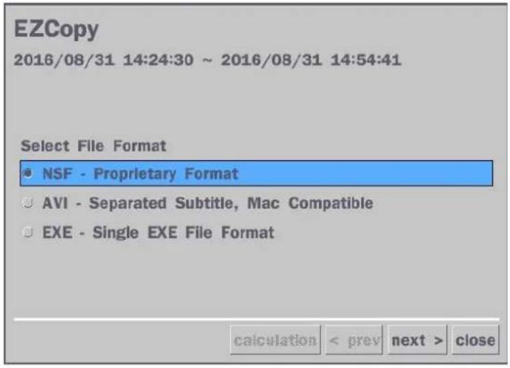
text_image
EZCopy 2016/08/31 14:24:30 ~ 2016/08/31 14:54:41 Select File Format ● NSF - Proprietary Format ○ AVI - Separated Subtitle, Mac Compatible ○ EXE - Single EXE File Format calculation < prev next > close- After backup format is selected, also select media type and channel(s) to archive the data to the media.
6-4. Transferring Still Images or Video from the ARCHIVE List
The stored data in the hard drive can be found in the ARCHIVE list in the SEARCH window.
User can back up still images or video into the storage device from the ARCHIVE list.
- Select the date to begin searching and navigate through the days using the mouse or the remote control.
- Once you have selected the date, press the NEXT button to open the list of stored data.
- Use the mouse or the remote control to scroll through the archive list.
- Select a list of stored events in the archive list.
- Once the desired event has been selected, press the DISPLAY button to view the still image or the first frame of the selected video.
- Press the BACKUP button to launch the archiving function in playback mode.
- Press the CLOSE button to return to the SEARCH window.
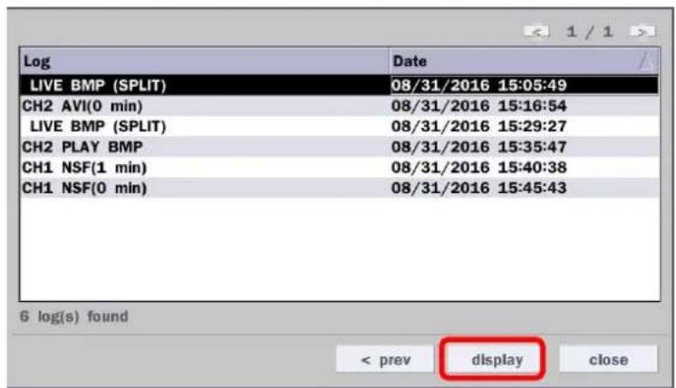
text_image
Log Date LIVE BMP (SPLIT) 08/31/2016 15:05:49 CH2 AVI(0 min) 08/31/2016 15:16:54 LIVE BMP (SPLIT) 08/31/2016 15:29:27 CH2 PLAY BMP 08/31/2016 15:35:47 CH1 NSF(1 min) 08/31/2016 15:40:38 CH1 NSF(0 min) 08/31/2016 15:45:43 6 log(s) found < prev display close
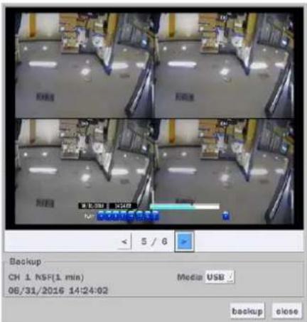
text_image
Backup CH 1 NSF(1 min) Media USB 08/31/2016 14:24:02 backup closeFigure 6.3.1. Archive Search Screen
6-5. Playback of Backup Video
6-5-1. AVI Format
AVI format: AVI format video can be played back by Window Media Player™ or other media player that is compatible with AVI format video.
- Please install the Decoder Filter that the DVR copies "DvrPlayer" folder on USB flash drive with the video. Decoder Filter is exported to the "/DvrPlayer" folder of the USB drive.

text_image
Computer > USB DRIVE (E:) > DvrPlayer Organize > Share with > Burn > New folder Homegroup Computer OS (C:) USB DRIVE (E:) CNC_Ctrl_Player.dll HDPlayer hi_h254dec_wm.dll Decoder Filter- Otherwise, the video and time stamp over video can't be properly played back and wont be displayed on Window Media Player™.

natural_image
Interior view of a museum or exhibition hall with wooden flooring, display cases, and ceiling lighting (no visible text or signage)
Timestamp On AVI. The subtitle is embedded to the video clip file.
The subtitle is embedded to the AVI file. To display a subtitle, user should install a special filter called "Decoder Filter".
6-5-2. NSF Format

NSF format: NSF format video can be played back using the HD player that the DVR copies to "DvrPlayer" folder on USB flash drive with video. Use the mouse scroll to use digital zoom in and out feature.
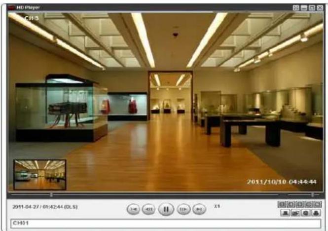
natural_image
Interior view of a museum gallery with wooden flooring, display cases, and ceiling lighting (no visible text or signage)7. Network Access Using the Multi-Sites Network Viewer
7-1. Overview
The SpecoTech Multi Client is a multiple site monitoring client software with; video, audio, and alarm signals from the DVRs over the network. The SpecoTech Multi Client does not limit the number of DVR units to register.
The program displays up to 16 DVRs and supports dual monitors.
On the program, user may control PTZ cameras on the DVRs. By attaching a microphone and speaker system to devices on site, the user may make bi-directional audio communication over the network.
7-2. PC Requirements
Minimum PC Requirements
| CPU | Intel Core i3 |
| 1.8Ghz | |
| Memory | 2GB DDR2 |
| VGA | 512MB |
| Resolution | 1280x720 |
| Disk Space | 1GB |
| OS | Windows 2000, XP Professional, XP Home, Vista, 7 (NOTE: Not all versions of Vista and 7 are supported) |
| Network | 10/100Base T |
| Others | Direct X 9.0c or Higher |
Recommended PC Requirements
| CPU | Intel Core i5 |
| 2Ghz or higher. | |
| Memory | 4GB DDR3 or higher. |
| VGA | 512MB or higher. |
| Resolution | 1920x1080 |
| Disk Space | 1GB |
| OS | Windows 2000, XP Professional, XP Home, Vista, 7 (NOTE: Not all versions of Vista and 7 are supported) |
| Network | 10/100/1000Base T |
| Others | Direct X 10 or higher. |
Before installing the program, check the PC specifications. The DVR remote software may not perform correctly if the PC does not meet the minimum requirements.
7-3. Installation of the Program
- Insert the provided CD in the CD drive and double-click "SpecoTech Multi Client (XXXX).exe"
- Select a destination folder and click "Next".
text_image
InstallShield Wizard Choose Destination Location Select folder where Setup will install files. Setup will install SpecoTech Multi Client in the following folder. To install to this folder, click Next. To install to a different folder, click Browse and select another folder. Destination Folder C:\...\Speco Technologies\SpecoTech Multi Client Browse... InstallShield < Back Next > Cancel- Select the program folder and click "Next".
text_image
InstallShield Wizard Select Program Folder Please select a program folder. Setup will add program icons to the Program Folder listed below. You may type a new folder name, or select one from the existing folders list. Click Next to continue. Program Folders: SpecoTech Multi Client Existing Folders: Accessories Administrative Tools Adobe AlViewer AnySoft avast! Free Antivirus CMS DTS+AC3 Filter DVR InstallShield < Back Next > Cancel- The installation status screen is displayed.
- After the installation is completed, "SpecoTech Multi Client" icon displays on the desktop screen.

SpecoTech
Multi Client
7-4. Live Window
When installation is completed, double click the "SpecoTech Multi Client" icon on your desktop to start the program.
7-4-1. Main User Interface
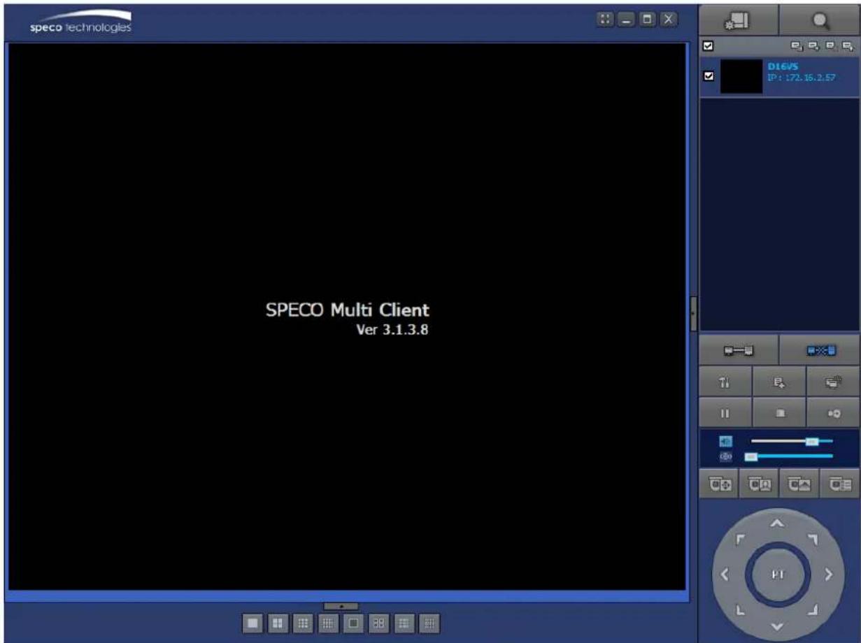
text_image
speco technologies D16VS IP: 172.16.2.57 SPECO Multi Client Ver 3.1.3.87-4-2. Control Buttons
| Button | Description | |
 LOCAL PLAYBACK LOCAL PLAYBACK | Click this icon to run a playback window to search and play videos that are recorded in the local PC. | |
 REMOTE PLAYBACK REMOTE PLAYBACK | Click this icon to run a playback window to search and play videos that are recorded in the remote DVR. | |
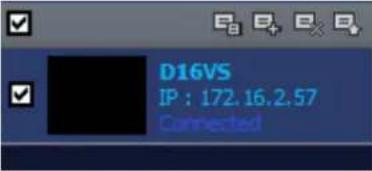 SITE MANAGEMENT SITE MANAGEMENT | THUMBNAIL REFRESH: Click this icon to refresh and renew thumbnail image of the connected sites.SITE ADDITION: Click this icon to open ‘Site Addition’ window.SITE DELETE: Click this icon to delete site from the index window, after disconnect a site.NET FINDER: Select the site from the index window and click this icon to modify the information of specific site. | |
 | CONNECT | Click this icon to connect the selected site/sites. |
 | DISCONNECT | Click this icon to disconnect the selected site/sites. |
 | SETUP | Click this icon to setup configuration of SpecoTech Multi Client. |
 | CAPTURE | Click this icon to capture a still image. |
 | EVENT LIST | Opens list of events logged by the SpecoTech Multi Client. |
 | PAUSE | Click this icon to play/pause live video. |
 | ALARM ON | Click this icon to turn on/off alarm outputs. |
 | RECORD ON | Enable or disable recording of live video to local disk, which has set in setup menu. |
 AUDIO AUDIO MIC MIC | Use the volume control bar to set the audio level. | |
| Use the microphone volume control bar to set the micro phone level. | ||
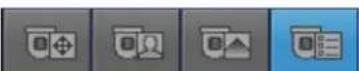 PRESET/TOUR/SCAN/MENU PRESET/TOUR/SCAN/MENU | User can control PRESET/TOUR/SCAN/MENU | |
 CHANNEL SPLIT CHANNEL SPLIT | To select the numbers of display channel/channels (Single, quad, 9 channels, and 16 channels) of highlighted site. | |
 DVR SITE SPLIT DVR SITE SPLIT | To select the numbers of DVR/DVRs (1 DVR, 4 DVRs, 9 DVRs, 1 DVRs) on main display screen. | |
7-5. Search and Playback Window
7-5-1. Main User Interface
You can access to search window by clicking the search icon (Local Playback / Remote Playback) on the upper right of the Live Window.
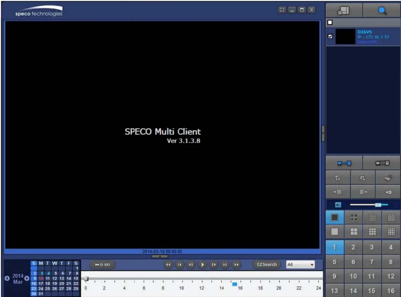
text_image
speco technologies D16VS IP: 172.16.2.57 Research SPECO Multi Client Ver 3.1.3.8 2014-03-10 00:00:00 S M T W T F S 2 3 4 5 6 7 8 9 10 11 12 13 14 15 16 17 18 19 20 21 22 23 24 25 26 27 28 29 30 31 H0-60 EZSearch All 2014 Mar S M T W T F S 1 2 3 4 5 6 7 8 9 10 11 12 13 14 15 16 17 18 19 20 21 22 23 24 25 26 27 28 29 0 2 4 6 8 10 12 14 16 18 20 22 247-5-2. Main Control Panel
| Button | Description | |
 LOCAL PLAYBACK LOCAL PLAYBACK | Click this icon to run a playback window to search and play videos that are recorded in the local PC. | |
 REMOTE PLAYBACK REMOTE PLAYBACK | Click this icon to run a playback window to search and play videos that are recorded in the remote DVR. | |
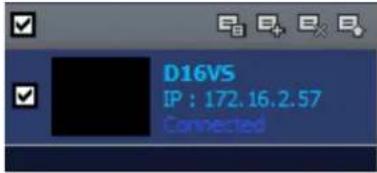 | Display the site information and the connection status. | |
 CONNECT CONNECT | Click this icon to connect the selected site/sites. | |
 DISCONNECT DISCONNECT | Click this icon to disconnect the selected site/sites. | |
 SETUP SETUP | Click this icon to setup configuration of SpecoTech Multi Client. | |
 CAPTURE CAPTURE | Click this icon to capture a still image. | |
 EVENT LIST EVENT LIST | Opens list of events logged by the SpecoTech Multi Client. | |
 EZCopy Start EZCopy Start | Click this icon to set the beginning time for backup of the recorded video in AVI format. | |
 EZCopy End EZCopy End | Click this icon to set the ending time for backup of the recorded video in AVI format. | |
 BACKUP BACKUP | Click this icon to backup the recorded video in AVI format. | |
 AUDIO AUDIO | Use the volume control bar to set the audio level. | |
 | To select the numbers of DVR/DVRs (1 DVR, 4 DVRs, 9 DVRs, 16 DVRs) on main display screen. | |
 | To select the numbers of display channel/channels (Single, quad, channels, and 16 channels) of highlighted site. | |
 | To select the channel to playback. | |
 | The calendar shows dates with recorded video in color. | |
 | To display the recorded data of selected channel or all channels on a time line scale. | |
 | To change a timeline scale from 24 hours to 60 minutes.The timeline shows recorded data in color on the bar. You can adjust the timeline scale and move it to the time you wish to playback. Then click the play icon to display the recorded video. | |
 | Playback buttons. | |
 | EZSEARCH: Thumbnail search over the network.- Shows 24 thumbnail images, one for each hour from 00:00 to 23:00.- Each hour is further broken up 24 segments; each is 150sec.- Then select the tile to play* Click the “PREVIOUS” button to go the previous step. | |
 | Digital Zoom Window in Live and Playback. (Only available in Single Channel Viewing) | |
7-5-3. SMART SEARCH
1) User can search with selected area
2) Click right mouse button when playback
text_image
speco technologies CHI 960 X 480 Aspect Ratio High Quality Normal Quality iFrame Only Smart Search FPB: 0 BitRate: 0.0 Kbps 0 2 4 6 8 10 12 14 16 18 20 22 24 EZSearch Time 0-60 CH-1
text_image
Aspect Ratio High Quality Normal Quality IFrame Only Smart Search3) 'Smart Search' will search in the selected area only.
4) 'Smart Search' checking the motion and event from the selected area.
5) User can set, Sensitivity, Internal, Thumbnail size, Date and Time

text_image
Smart Search - CH01 Mouse Button - Left(Select), Right(Unselect) Date/Time Sensitivity Low —— High Interval 1 sec Thumbnail Size Option Date/Time Format: YYYY-MM-DD Time Start 2015-04-29 0.0% End 2015-04-29 0.0% 0.0% Start Stop
text_image
Smart Search - CHO1 2015-04-29 06:56:59 Mouse Button - Left(Select), Right(Unselect) Sensitivity Interval Thumonail Size Low High 1 sec Option Date/Time Format YYYY-MM-DD Time Start 2015-04-29 오전 6:50:45 End 2015-04-29 오후 6:59:45 0.0% Date/Time 2015-04-29 06:53:42 2015-04-29 06:53:43 2015-04-29 06:56:01 2015-04-29 06:56:02 2015-04-29 06:56:03 2015-04-29 06:56:04 2015-04-29 06:56:08 2015-04-29 06:56:09 2015-04-29 06:56:10 Start Stop6) Select any of search Thumbnail then selected event will playing.
Setup of SpecoTech Multi Client
Click the setup icon to setup the configuration of SpecoTech Multi Client software. The SETUP window is displayed as below.
7-6-1. General
Security Option: Set a password for security options. Select security options and set a password. Then when you access any of selected functions, you need to enter the password. You can also set the save path for capturing and backup.
Save Path: Specify the location to save captured still image for Capture and Backup data.
Miscellaneous
Automatic Reconnection: If enabled, the software will automatically try to reconnect to the last successful IP address. But, when CLIENT ACCESS is OFF on the DVR, the software will not try to reconnect even if it is enabled.
Always On Top: If enabled, the software display will be continuously on the top of other windows.
Time Format: Change the way the Client software displays the time.
text_image
Setup General Event Event search Record Disk Display Language About Security Option Startup Shutdown Setup Local Playback Remote Playback Password... Save Path Capture : C:\Storage\Capture\ Backup : C:\Storage\Backup\ Miscellaneous Automatic reconnection Always On Top Time Format : YYYY-MM-DD OK Cancel7-6-2. Event
Event log can be archived and searched.
Event Log: Specify the location to save event logs and select event to archive.

text_image
Setup General Event Event search Record Disk Display Language About Log Path : C:\Storage\Log\ Size : 10 (MAX : 100MB) Event Log Event list Startup ✓ ✓ Shutdown ✓ ✓ Setup Change ✓ ✓ Sensor in ✓ ✓ Alarm out ✓ ✓ Motion ✓ ✓ Camera loss ✓ ✓ Network loss ✓ ✓ Record ✓ ✓ OK CancelEvent Search: Event log can be searched from the selected time.
text_image
Setup General Event Event search Record Disk Display Language About From: First 2011-04-26 12:00:00 AM To: Last 2011-04-26 7:48:54 PM Path: C:\Storage\Log\ Find Browse Type Site Address Event Date/Time Save OK Cancel7-6-3. Record
Record Setup: You can set the recording conditions as the following; Always, Event, or Auto record. And you can also select target DVR/DVRs and channel/channels. When you set the recording condition to event, you can set event for motion or alarm with duration.

text_image
Setup General Event Event search Record Disk Display Language About Record Condition Always Event Auto record Event Motion Alarm Duration: 5 Sec Channel Site : Site 1 All site All NO. CH 1 Channel 1 2 Channel 2 3 Channel 3 4 Channel 4 5 Channel 5 6 Channel 6 OK CancelRecord Local Storage Setup: You can select the local disk to record and the amount of disk space you want to allow the program to use for recording. You can also select the option to overwrite data or stop recording when the maximum amount of disk space is full.
text_image
Setup General Event Event search Record Disk Display Language About Disk Space : C:1 4 GB Disk Info Total space : 465 GB Free space : 398 GB Disk full Replace oldest files. Stop recording. OK Cancel7-6-4. Display
You can select the OSD (On Screen Display) to be displayed.

text_image
Setup General Event Event search Record Disk Display Language About OSD Site : Site 1 All site Info Display network statistics Date/Time Event ✓ Alarm ✓ Motion ✓ Sensor ✓ Record ✓ Video Loss Display Secondary monitor image correction Please use this option only on the PC when having a shattered image on the secondary monitor during use of multi monitor. If option is enabled, the performance of the program may drop. OK Cancel7-6-5. Language
English, French and Spanish is selectable.
text_image
Setup General Event Event search Record Disk Display Language About Language : English French English Spanish OK Cancel7-6-6. About
"About" provides network client version information.
text_image
Setup General Event Event search Record Disk Display About SPECO Multi Client Version 3.0.4.4 (Build 110524) Copyright (C) 2011 This product licensed to : Warning: this computer program is protected by copyright law and international treaties. Unauthorized reproduction or distribution of this program, or any portion of it, may result in severe civil and criminal penalties, and will be prosecuted to the maximum extent possible under the law. OK Cancel7-7. Remote Setup
The menu settings for the DVR unit can be set over network.
Put the cursor of the mouse on the channel, which is connected to the site and right click on the mouse to open the submenu. Then the following window is displayed as below. Select the REMOTE SETUP.

text_image
speco technologies CH2 NO VIDEO CH3 NO VIDEO CH4 NO VIDEO CH5 NO VIDEO CH7 NO VIDEO CH8 NO VIDEO CH9 NO VIDEO CH10 NO VIDEO CH11 NO VIDEO CH12 NO VIDEO CH13 NO VIDEO CH14 NO VIDEO CH15 NO VIDEO CH16 NO VIDEO Disconnect High Quality Normal Quality JFrame Only Setup Remote Setup Lock Site Information Full Screen Aspect Ratio ExitThen the setup window is displayed. The specified menu screen is displayed on the upper left of the screen.
Enter the password of the DVR when prompted. (NOTE: The default password is 1111)
Setting is the same as with the DVR menu setting. Refer to the corresponding pages for details on the setting items.
text_image
SPECO WEB SETUP PASSWORD: LOGIN
NOTICE
Web Setup is prohibited when DVR is in local Setup Menu.

text_image
Remote setup SPECO WEB SETUP (1.0.48) PASSWORD: LOGIN THE SYSTEM IS NOT IN THE LIVE MODE. REMOTE SETUP IS PROHIBITED AT THIS TIME.7-7-1. System
Select System to set system and time settings.

text_image
SYSTEM RECORD DEVICE DISPLAY NETWORK USER MANAGEMENT STORAGE UPGRADE INFORMATION DATE DISPLAY FORMAT CLIENT ACCESS NTP SETUP PRIMARY SNTP SERVER SECONDARY SNTP SERVER TIME ZONE CONNECTION MODE CONNECTION PERIOD SEND EMAIL SETUP SERVER TYPE MAIL SERVER MAIL PORT SECURE OPTION ID PASSWORD MAIL TO MAIL FROM SEND MAIL TEST UNIT NAME SYSTEM RESTART SYSTEM EVENT NOTIFICATION MM/CD/YYYY OK OFF ON Pool.rnp.org Time.nst.gov GMT -5.00 (Montreal/New York) TIME 03:00 AM OFF MIN/CAV 25 CNR APPLY MAIL SETTING & TEST CVR SYSTEM RESTART DISK EVENT SETUP HEALTH CHECK PERIOD DAILY POST 100 H HDD TEMPERATURE 60°C 140°F HDD BAD SECTORS 10% HDD ALMOST FULL 90% VIDEO CLIP SETUP PRE RECORD 2 SECOND(S) POST RECORD 1 SECOND(S) EVENTS AND NOTIFICATION ALARM-OUT BEEP E-MAIL HEALTH CHECK - - YES RESTART - - YES SHUTDOWN - - YES PANIC RECORD - - YES ALARM-IN OFF - NO MOTION DETECTION OFF - NO VIDEO LOSS OFF NO NO HDD TEMPERATURE 1 YES NO HDD BAD SECTORS - - YES HDD ALMOST FULL - - YES HDD FULL - - YES HDD FAILURE OFF YES YES http://172.16.2.57/cgi-bin/websetup.cgi#tabs-4 RELOAD APPLY• DATE DISPLAY FORMAT: Select the date display format.
- CLIENT ACCESS: Enable/Disable remote access through network client software.
- NTP SETUP: Sets whether to synchronize the time using NTP server or not.
o Primary SNTP Server: Input the NTP primary server address.
Secondary SNTP Server: Input the NTP secondary server address.
- Time Zone: Select the time zone.
- Connection Mode: Select the connection mode to NTP time server.
- SEND E-Mail SETUP: Sets whether to enable/disable e-mail sending function.
- SEVER TYPE: Select GMAIL, HOTMAIL, AOL, YAHOO or MANUAL)
- MAIL SERVER: Input the SMTP server name as well as the user ID and password.
- MAIL PORT: Mail port setting.
- SEURE OPTION: Select a secure mail server connection. (SSL or TLS)
○ ID : Email User ID - PASSWORD : Email User Password
- MAIL TO: Input the appropriate email address to enable sending e-mail reports
- MAIL FROM (Return Mail Address): Set the source e-mail address to be notified to the destination.
- SEND MAIL TEST: Examine the function with registered information.
- USER NAME: Name the DVR
- SYSTEM RESTART
• SYSTEM EVENT NOTIFICATION
Allows the user to set EVENT NOFICIATION ON or OFF
○ HEALTH CHECK
(Allows the user to set MAIL STATUS periodically) : DAILY or WEEKLY or MONTHLY
○ HDD TEMPERATURE
- HDD BAD SECTOR
- HDD ALMOST FULL
- VIDEO CLIP SETUP: Setting the duration for pre and post recording.
- EVENTS AND NOTIFICATION
○ HEALTH CHECK / RESTART / SHUTDOWN / PANIC RECORD
Enable Email Notification in the event a problem occurs with the VT.
- ALARM-IN : Enable Email Notification when the camera detects sensor
- MOTION DETECTION : Enable Email Notification when the camera detects motion
- VIDEO LOSS: Enable Email, Beep and Alarm output Notification when the camera signal is lost.
- HDD TEMPERATURE : Enable Email Beep and Alarm output Notification when the HDD reaches the maximum temperature
- HDD BAD SECTOR: Enable Email Notification when the HDD has bad sectors.
- HDD ALMOST FULL: Enable Email Notification when the HDD is almost full.
- HDD FULL: Enable Email Notification when the HDD is full.
- HDD FAILURE: Enable Email, Beep and Alarm output Notification when the HDD fails.
7-7-2. Record
Select RECORD tab to set the recording conditions.
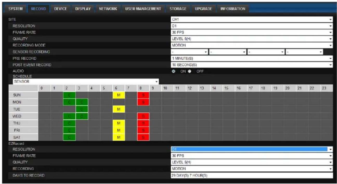
text_image
SYSTEM RECORD DEVICE DISPLAY NETWORK USER MANAGEMENT STORAGE UPGRADE INFORMATION SITE CH1 RESOLUTION D1 FRAME RATE 30 FPS QUALITY LEVEL 5(H) RECORDING MODE MOTION SENSOR RECORDING PRE RECORD 1 MINUTE(S) POST EVENT RECORD 10 SECOND(S) AUDIO ON OFF SCHEDULE SENSOR 0 1 2 3 4 5 6 7 8 9 10 11 12 13 14 15 16 17 18 19 20 21 22 23 SUN C M S MON C C S TUE C C M WED C C S THU C M S FRI C M S SAT C M S EZRecord RESOLUTION D1 FRAME RATE 30 FPS QUALITY LEVEL 5(H) RECORDING MOTION DAYS TO RECORD 29 DAY(S) 7 HOUR(S)These settings apply to the specified channel only.
- Recording Setup
o RESOLUTION: Sets the resolution for the recordings. The value applies to an individual channel.
o FRAME RATE: Sets the recording rate.
o QUALITY: Sets the image quality in 5 levels.
o RECORDING: Sets the recording mode.
o RECORDING MODE: CONTINUOUS, SCHEDULE, MOTION, SENSOR
o PRE RECORD: Sets whether to perform or not pre recording.
o POST EVENT RECORD: Sets the duration of the event recording.
o AUDIO: Sets whether to perform or not audio recording.
o SECHDULE: Sets the schedule recording.
These settings apply to all channels.
- EZRECORD
o RESOLUTION: Sets the resolution for the recordings. The set value applies to an individual channel.
o FRAME RATE: Sets the recording rate.
o QUALITY: Sets the image quality in 5 levels.
o RECORDING MODE: Sets the recording mode.
o RECORD DAYS: By the setting value, the Recording Days will change accordingly.
7-7-3. Device
Select Device to set Spot Out, Enable/Disable CVBS Out, motion zone.
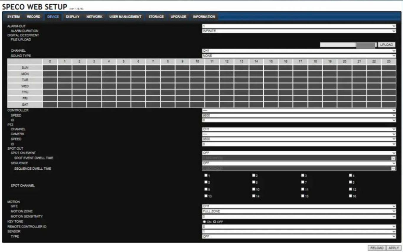
text_image
SPECO WEB SETUP SYSTEM RECORD DEVICE DISPLAY NETWORK USER MANAGEMENT STORAGE UPGRADE INFORMATION ALARM-OUT ALARM DURATION DIGITAL DETERRENT FILE UPLOAD CHANNEL CH1 SOUND TYPE NONE 0 1 2 3 4 5 6 7 8 9 10 11 12 13 14 15 16 17 18 19 20 21 22 23 SUN MON TUE WED THU FRJ SAT CONTROLLER SPEED ID PTZ CHANNEL CAMERA SPEED ID SPOT OUT SPOT ON EVENT SPOT EVENT DWELL TIME SEQUENCE SEQUENCE DWELL TIME OFF 1 subconors OFF 1 subconors ■ 1 ■ 2 ■ 3 ■ 4 ■ 5 ■ 6 ■ 7 ■ 8 ■ 9 ■ 10 ■ 11 ■ 12 ■ 13 ■ 14 ■ 15 ■ 16 SPOT CHANNEL MOTION SITE MOTION ZONE MOTION SENSITIVITY KEY TONE REMOTE CONTROLLER ID SENSOR TYPE CH1 FULL ZONE 5 ON OFF 0 OFF RELOAD APPLY• ALARM OUT: Set the alarm out duration.
- DIGITAL DETERRENT: Set the schedule of digital deterrent function and upload the sound file to DVR.
• CONTROLLER: Set the controller baud rate and ID.
• PTZ: Set the PTZ baud rate, protocol, and ID.
- SPOT: Enable/Disable the SPOT OUT and SEQUENCE.
- MOTION: Setup the motion detection area and the sensitivity.
- SITE: Select the channel
o MOTION ZONE: FULL Zone or PARTIAL Zone
o MOTION SENSITIVITY: 1\~9 (High sensitivity level)
• KEYTONE: Sets On or Off of Key Tone.
- REMOTE CONTROLLER ID: Sets an ID number on the supplied remote control for its identification.
- SENSOR: Select the type of each sensor.
7-7-4. Display
Select the DISPLAY tab to set the DISPLAY conditions.

text_image
SYSTEM RECORD DEVICE DISPLAY NETWORK USER MANAGEMENT STORAGE UPGRADE INFORMATION OSU CHANNEL NAME ON O VIDEO LOSS ON O STATUS BAR / ICON ON O OSD CONTRAST 100 MAIN MONITOR SEQUENCE ON O SEQUENCE-DWELL TIME 3 SECONOS SITE CH1 NAME CH1 COVERT OFF BRIGHTNESS 45 CONTRAST 40 RUE 50 SATURATION 50These settings apply to all channels.
- OSD: Sets whether to display or not, the date and time as well as channel number on the screen.
- OSD CONTRAST: Adjust the character contrast on the screen.
• MAIN MONITOR SEQUENCE: Setting for automatically switching the displayed video.
SEQUENCE DWELL TIME: Sets the interval for automatically switching the screens.
• SITE: Name, Covert, Brightness, Contrast, Hue, Saturation
These settings apply to the specified channel only.
7-7-5. Network
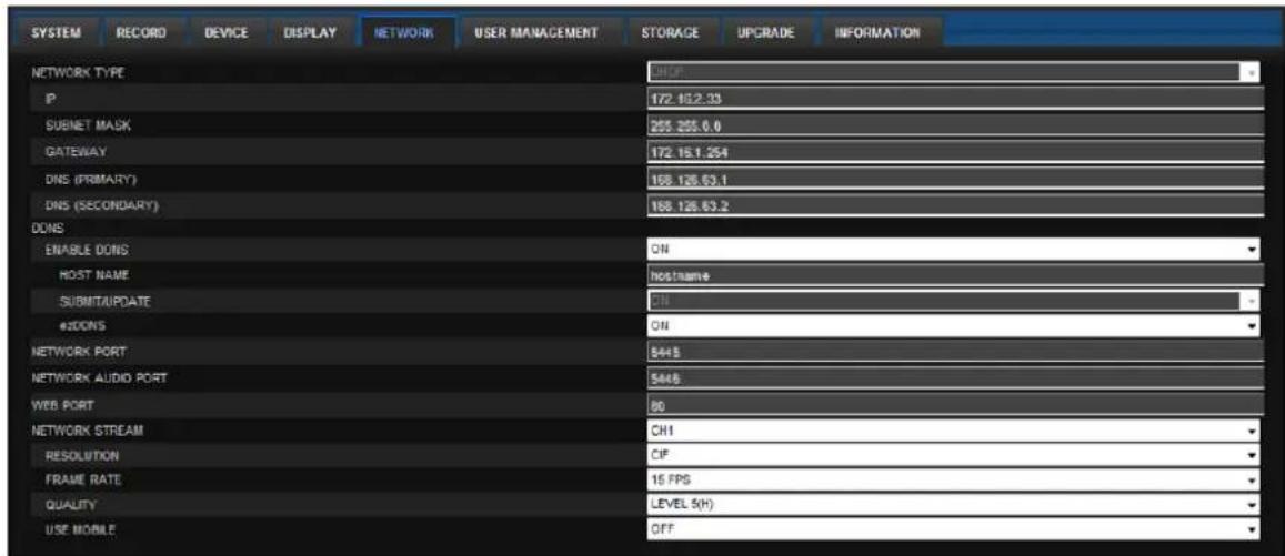
text_image
SYSTEM RECORD DEVICE DISPLAY NETWORK USER MANAGEMENT STORAGE UPGRADE INFORMATION NETWORK TYPE IP 172.16.2.33 SUBNET MASK 255.255.0.0 GATEWAY 172.16.1.254 DNS (PRIMARY) 158.126.63.1 DNS (SECONDARY) 158.126.63.2 DDNS ENABLE DONS ON HOST NAME hostname SUBMITUPDATE ON #DDNS ON NETWORK PORT 5448 NETWORK AUDIO PORT 5448 WEB PORT 80 NETWORK STREAM CH1 RESOLUTION OF FRAME RATE 15 FPS QUALITY LEVEL 5(H) USE MOBILE OFF- NETWORK TYPE
- STATIC: The address setting mode is manual. Input IP, Gateway, Subnet Mask, and DNS IP.
- DHCP: The address setting mode is automatic.
- DDNS: Set whether to use DDNS service or not.
○ HOST NAME: Allows the user to setup a domain name manually
o SUMBIT/UPDATE: Select ON to submit the settings
- ezDDNS: Enable/disable ezDDNS to register the host name automatically
• NETWORK PORT: When connecting multiple DVRs to the network, set a unique port number.
• NETWORK AUDIO PORT: Display the network audio port (NETWORK PORT + 1).
- WEB PORT: Set a web server port number.
- NETWORK STREAM: Set the Resolution, Frame Rate, and the Quality and enable/disable USE MOBILE.
7-7-6. User Management
Select the USER MANAGEMENT tab to set the DISPLAY conditions.

text_image
SPECO WEB SETUP SYSTEM RECORD DEVICE DISPLAY NETWORK USER MANAGEMENT STORAGE UPGRADE INFORMATION AUTHORITY SETUP PASSWORD CHECK ADMIN USER1 USER2 USER3 PASSWORD SETUP PS PTZ REC OFF NETWORK USER NAME SETUP NEW USER NAME PASSWORD SETUP CHANGE NEW PASSWORD CONFIRM PASSWORD PLAYBACK AUTHORITY 1 2 3 4 5 6 7 8 9 10 11 12 13 14 15 16 ADMIN USER1 USER2 USER3 USER1 USER1 ADMIN KEEP RELOAD APPLY7-7-7. Storage
Select Storage to configure continued recording settings by overwriting the hard disk and the storage period for the recording data.

text_image
SPECO WEB SETUP SYSTEM RECORD DEVICE DISPLAY NETWORK USER MANAGEMENT STORAGE UPGRADE INFORMATION OVERWRITE DISK INFO HDD SIZE : 435 GB (FREE : 431 GB) HDD LAST TIME : 03/10/2014 15:53:00 HDD 1 MODEL NAME ST35004108V TEMPERATURE 24 Celsius (75 Fahrenheit) HEALTH (GOOD/NORMAL/BAD) GOOD REALLOCATED SECTORS 0 CURRENT PENDING SECTORS 0 UNCORRECTABLE SECTORS 0 SPIN RETRY SECTORS 0 RECORDING LIMIT OFF RECORDING LIMIT DAYS REDUCTED RELOAD APPLY• OVERWRITE: Continues recording by writing over previous recordings when HDD is full.
- DISK INFO: Shows the information of HDD installed in DVR
- RECORDING LIMIT: Sets whether to limit or not, the recording data storage period.
7-7-8. Remote Upgrade
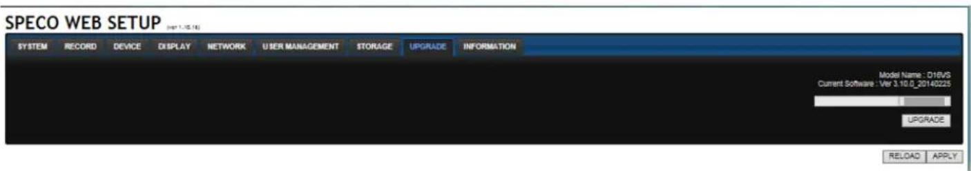
text_image
SPECO WEB SETUP (net 1.15.16) SYSTEM RECORD DEVICE DISPLAY NETWORK USER MANAGEMENT STORAGE UPGRADE INFORMATION Model Name: D16VS Current Software: Ver 3.10.0_20140225 UPGRADE RELOAD APPLYShows the current Firmware version installed on DVR.
- Browse: Select BROWSE to locate the firmware file.
- Upgrade: Select UPGRADE to upgrade the firmware of the DVR.
7-8. Operation
7-8-1. Addition, Delete, and Modify of DVR Sites
7-8-1-1. Addition of Sites
- Click SITE ADDITION button. And then the following window will be displayed as below.

text_image
Site Addition Site Info Site name : D16VS Site address : 172.16.2.57 Port number : 5445 ID : admin Password : ••••• OK Cancel- Site Name: Input a name that properly describes a site.
- IP Address: Input IP address (Public IP address of a router that DVR is connected.) or Domain name
- Port Number: Default Port Number is "5445".
- ID: Input ID of DVR. Default ID is "admin".
-
Password: Input network password of DVR. Default Password is "1111".
-
Click OK button. And then the registered site is added on the directory window.
text_image
D16VS IP : 172.16.2.57 Connected7-8-1-2. Deleting a Site
- Select the site/sites to delete from the directory window.

text_image
D16VS IP : 172.16.2.57 Connected- Click SITE DELETE button. And then the selected site/sites is/are deleted.

7-8-1-3. Modify of Sites
- Select the site/sites to modify from the directory window.
text_image
D16VS IP : 172.16.2.57 Connected- Click NET FINDER button. And then the following window will be displayed as below.

text_image
Net Finder Name Address D 16VS 172.16.2.57 Address Port No. Mac Model Add Modify Delete Find IP Change Close- Click MODIFY button. And then the modified information is displayed as below.
text_image
Site Modify Site Info Site name : D16VS Site address : 172.16.2.57 Port number : 5445 ID : admin Password : ••••• Channels Channels 16 CH ✓ Display Device Channel name Ch No. Name 1 CH1 2 CH2 3 CH3 4 CH4 5 CH5 OK Cancel7-8-2. Connect and Disconnect
7-8-2-1. Connect
- Select site/sites to connect from the directory window.
text_image
D16VS IP : 172.16.2.57 Connected
- Click CONNECT button, and then site/sites displays/display as connected.
text_image
space technologies CH2 NO VIDEO CH3 NO VIDEO CH4 NO VIDEO Connect High Quality Normal Quality Frame Only Setup Remote Setup Lock Site Information Full Screen Aspect Rate Exit CH5 NO VIDEO CH7 NO VIDEO CH8 NO VIDEO CH9 NO VIDEO CH10 NO VIDEO CH11 NO VIDEO CH12 NO VIDEO CH13 NO VIDEO CH14 NO VIDEO CH15 NO VIDEO CH16 NO VIDEO7-8-2-2. Disconnect
- Select site/sites to disconnect from the directory window.

text_image
D16VS IP : 172.16.2.57 Connected
- Click DISCONNECT button, and then selected site/sites disconnected.

text_image
SPECO Multi Client Ver 3.1.3.87-8-3. Still-image Capture During Live
- Double-click a channel to capture from the display screen. (Otherwise all channels will be captured.).

text_image
Street surveillance comparison image showing two quadrants with camera and ground overlays, one pointing to a building exterior view.
- Click CAPTURE button. And then a Capture window will be displayed as below.

text_image
Capture Save Path : s\martin\Documents\Speco\Capture\D16VS Browse File name : 2014-03-10-163522 File Format : BITMAP(*.BMP) OK Cancel- Set Save Path, File Name, and File Format. And then click OK button.
- Still image is saved as set in Capture window.
text_image
Storage Capture D4VS Organize Include in library Share with Slide show Burn New folder Documents Music Pictures Videos Homegroup Computer Local Disk (C:) DVD RW Drive (D:) BackupDisc DATA HDD (E:) 2 items 2011-07-19-112606 2011-07-19-1129227-8-4. Recording Video on Local PC During Live
- Click SETUP button. And then a setup window will be displayed as below.
- Select Record and set the values.
text_image
Setup General Event Event search Record Disk Display About Record Condition Always Event Auto record Event Motion Alarm Duration: 5 Sec Channel Site : Site 1 All site All NO. CH 1 Channel 1 2 Channel 2 3 Channel 3 4 Channel 4 5 Channel 5 6 Channel 6 OK Cancel- Select Disk and set the values.

text_image
Setup General Event Event search Record Disk Display About Disk Space : C:\ 4 GB Disk Info Total space : 465 GB Free space : 398 GB Disk full Replace oldest files. Stop recording. OK Cancel- Click RECORD ON button. And the color of button is changed.
- Live video data is recorded as set in Record and Disk setup. These video data can be searched and play-backed with Local Playback.
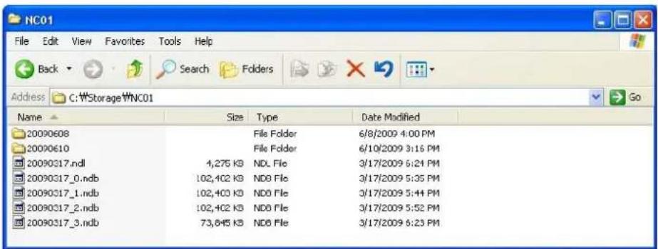
text_image
NC01 File Edit View Favorites Tools Help Back Search Folders Address C:\Storage\NC01 Go Name Size Type Date Modified 20090608 File Folder 6/8/2009 4:00 PM 20090610 File Folder 6/10/2009 3:16 PM 20090317.ndl 4,275 KB NDL File 3/17/2009 6:24 PM 20090317_0.ndb 102,402 KB NDB File 3/17/2009 5:35 PM 20090317_1.ndb 102,403 KB NDB File 3/17/2009 5:44 PM 20090317_2.ndb 102,402 KB NDB File 3/17/2009 5:52 PM 20090317_3.ndb 73,845 KB NDB File 3/17/2009 6:23 PM7-8-5. Local Playback and Remote Playback
7-8-5-1. Playback of Recorded Video on a Local PC
- Click LOCAL PLAYBACK. And then Playback Window will be displayed over the Live Window.
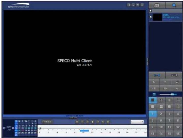
text_image
SPECO Multi Client Ver 3.0.4.4 2019-07-01:00:00:00 M T W T, E 5 4 5 6 7 8 9 10 11 12 13 14 15 16 17 18 19 20 21 22 23 24 25 26 27 28 29 30 H:0:00 1 2 3 4 5 6 7 8 9 10 11 12 13 14 15 16- Select site/sites to connect from the directory window.

- Click CONNECT button. And then Green bar displays on Search calendar and timeline scale window.

text_image
2011 Apr S M T W T F S 1 2 3 4 5 6 7 8 9 10 11 12 13 14 15 16 17 18 19 20 21 22 23 24 25 26 27 28 29 30 0 2 4 6 8 10 12 14 16 18 20 22 24- Move the marker on the timeline scale to where there is video data and press the PLAY button.

- Video data that is recorded on local PC will be play-backed.
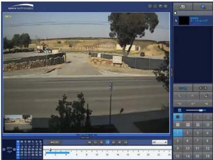
text_image
Screenshot of a video editing software interface showing a highway scene with trees and buildings, alongside a timeline and control panel.- Use the mouse scroll to digitally zoom in and out from a single channel display.
7-8-5-2. Playback of Recorded Video on Remote DVR
- Click REMOTE PLAYBACK. And then Playback Window will be displayed.
text_image
SPECO Multi Client Ver 3.1.3.8 2014-03-19 05:36:00 M T W T F S 2 4 5 6 7 8 17 12 13 14 15 17 18 19 20 21 22 26 25 26 27 28 29 0 2 4 6 8 10 12 14 16 18 20 22 24 E:\Search As 0 2 4 6 8 10 12 14 16 18 20 22 24 13 14 15 16-
Select the site to connect from the directory window.
-
Click CONNECT. And then Green bar displays on Search calendar and timeline scale.

text_image
2011 Apr S M T W T F S 3 4 5 6 7 8 9 10 11 12 13 14 15 16 17 18 19 20 21 22 23 24 25 26 27 28 29 30 0 2 4 6 8 10 12 14 16 18 20 22 24- Move the marker on the timeline scale to where there is video data and press the PLAY button.

- Video data that is recorded on the remote DVR is play-backed.

text_image
speco technologies LM-1 2011 Apr MTWTF5 1 2 4 5 6 7 8 9 10 11 12 13 14 15 16 17 18 19 20 21 22 23 25 26 27 28 29 30 0 2 4 6 8 10 12 14 16 18 20 22 24 0 0 0 0 0 0 0 0 0 0 0 0 0 0 0 0 0 0 0 0 0 0 0 0 0 0 0 0 0 0 0 0 0 0 0 0 0 0 0 0 0 0 0 0 0 0 0 0 0 0 M T W T F S 1 2 4 5 6 7 8 9 10 11 12 13 14 15 16 17 18 19 20 21 22 23 25 26 27 28 29 30 0 2 4 6 8 10 12 14 16 18 20 22 247-8-6. AVI Backup during Playback
You can back up the recorded videos in AVI format during playback.
- Double-click the target channel to backup.
- Select the beginning time by using the search calendar and timeline scale bar.

text_image
2011 Apr S M T W T F S 3 4 5 6 7 8 9 10 11 12 13 14 15 16 17 18 19 20 21 22 23 24 25 26 27 28 29 30 0 2 4 6 8 10 12 14 16 18 20 22 24- Click EZCOPY START button on the timeline scale to select the beginning point of the backup.

text_image
0 10 20 30 40 50 60- Click EZCOPY END button on the timeline scale to select the ending point of the backup. Then, the selected starting point and the ending point on the timeline scale bar will be marked in green.

bar
| Range | Value | |-------|-------| | 0-10 | 0 | | 10-20 | 0 | | 20-30 | 0 | | 30-40 | 0 | | 40-50 | 0 | | 50-60 | 0 |- Click BACKUP. And then the BACKUP window will be displayed as below.
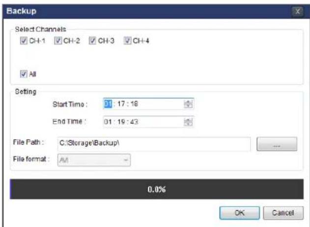
text_image
Backup Select Channels CH-1 CH-2 CH-3 CH-4 All Setting Start Time : 11:17:18 End Time : 01:19:43 File Path : C:\Storage\Backup\ File format : AM 0.0% OK Cancel- You can also set the beginning time and ending time on this window. After selecting a channel for backup, click the OK button. The backup will begin.

text_image
Backup Select Channels CH-1 CH-2 CH-3 CH-4 All Setting Start Time: 01:17:10 End Time: 01:19:43 File Path: C:\Storage\Backup\ File format: AVI 7.6% OK Cancel- AVI video data is recorded as selected in AVI Backup window. AVI format video can be played back by using Window Media Player™ or other media player that is compatible with AVI format video.
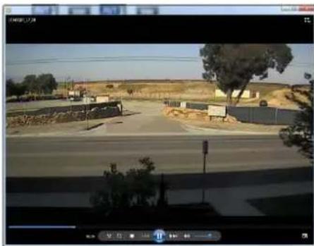
natural_image
Exterior view of a rural road with buildings and trees, captured in an outdoor scene (no visible text or symbols)8. Network Access Using the Web-Browser Viewer
The DVR provides a live remote monitoring feature by web-browser viewer. (NOTE: Web-Browser is only available for Internet Explorer)
- Check the IP address of the DVR from SETUP>SYSTEM>DESCRIPTION>IP ADDRESS or
- Input the IP address or Domain name address that you pre-registered.

text_image
Address http://172.16.1.52 Go- Click this bar. Then the dialog box is displayed.

text_image
This site might require the following ActiveX control: 'WebViewer' from Click here to install...- Click "Install" to download and install the ActiveX control.
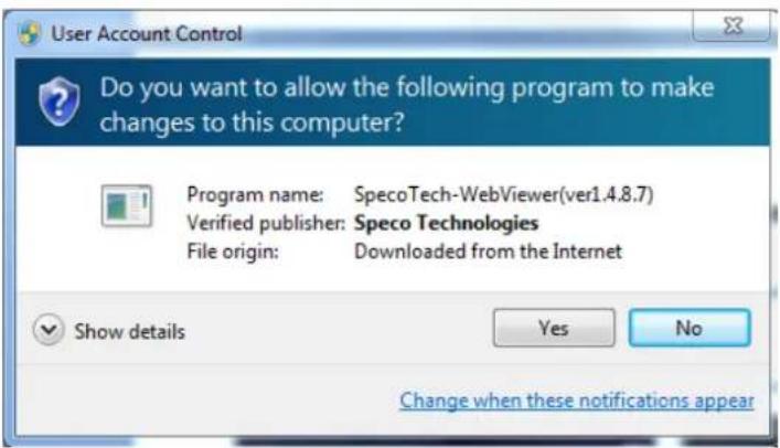
text_image
User Account Control Do you want to allow the following program to make changes to this computer? Program name: SpecoTech-WebViewer(ver1.4.8.7) Verified publisher: Speco Technologies File origin: Downloaded from the Internet Show details Yes No Change when these notifications appear- The Web Browser Viewer will be displayed as below after the ActiveX installation

text_image
Connect Live Search 2011-04-26 21:12:27 speco technologies Web Client Ver 1.4.8.7 PPS : 0 Bit rate : 0 Kbps Type Site Event Date/Time Info Initialize success 2011-04-26 21:10:46- Click the CONNECT button on the Left upper corner of web-viewer. Then "Connect" dialog is displayed.

text_image
Connect -- Webpage Dialog http://192.168.1.12/login.html Connect to remote system Address 192.168.1.12 Port 5445 ID admin Password •••••| Connect Cancel- Site Name: Input a name that properly describes a site.
- IP Address: Input IP address (Public IP address of a router that DVR is connected.) or Domain name
- Port Number: Default Port Number is "5445".
• ID: Input ID of DVR. Default ID is "admin". -
Password: Input network password of DVR. Default Password is "1111".
-
Then the cameras connected to the DVR are displayed on the screen.
- Use mouse scroll to digitally zoom in and out from a single channel display.

text_image
speco technologies CH 1 CH 2 CH 3 CH 4 FPS : 115 BitRate : 1847kbps Type Site Event Date/Time Info 192.188.1.12:5445 Camera detected CH 1 2011-04-27 08:54:34 Info 192.188.1.12:5445 camera detected ch 2 2011-04-27 08:54:34 Info 192.188.1.12:5445 camera detected ch 3 2011-04-27 08:54:33 Info 192.188.1.12:5445 camera detected ch 4 2011-04-27 08:54:33 Info 192.188.1.12:5445 link connected 2011-04-27 08:54:33 Info 192.188.1.12:5445 camera detected ch 7 2011-04-27 08:54:339. Network Access Using the Smart Phone Viewer

Notice
Data Usage applied without Wi-Fi connection. Please check with your Phone Carrier.
9-1. App Viewer for iPhone
- Enter the Apple App Store.


- Search "Speco Player" in the App Store.

Notice
SPECO Player is for the VT, HT, HS, ZS, NS, DS, RS, WRS and HD series DVRs. SPECO VIEWER is not compatible with the T Series DVR's (TH, TN or TL) or the PC
9-1-1. Live
- Open the installed "Speco Player" App and click

button to add a remote device.
- Enter the site name, IP or DDNS address, Network Port number (default 5445), ID(default admin) and Password (default 1111). Then, click "Save" button.
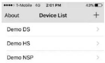
text_image
About Device List + Demo DS > Demo HS > Demo NSP >* Note: Network Port and Web Port must be forwarded before adding a new site.
- Select a registered device and select "Live". Then click "Connect" button.

text_image
Device List Demo HS Edit Connect Playback Live Remote Log SITE INFORMATION Site: Demo HS IP/DNS: demohs.ddns.specoddns.net Port: 5800 ID: user Password: ****- The app will display the selected channel(s). Double tap the channel screen to switch 1 channel display to 4, 8, 10, 16 channels split display depending on the DVR.
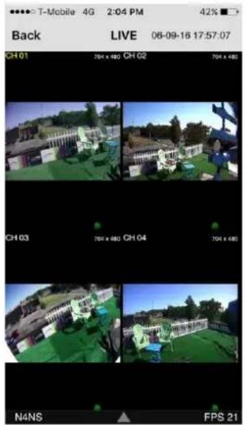
text_image
T-Mobile 4G 2:04 PM 42% Back LIVE 06-09-16 17:57:07 CH 01 CH 02 704 x 480 CH 03 CH 04 704 x 480 CH 04 N4NS FPS 21

natural_image
Outdoor scene with a white fence, green patio, and small furniture (no visible text or symbols)- To select the display mode(1, 4, 9, 10 or 16 split display), tap the arrow menus button

text_image
T-Mobile 4G 2:05 PM Back LIVE 06-09-16 17:57:37 CH 01 704 x 450 N4NS FPS 30 1 4 9 10 16 PTZ ZOOM FOCUS- Drag and drop channels
Touch and drag one channel to the other channel to swap the channel location. To swap the channel, drag a channel to another channel.
- Digital Zoom In-Out
Double tap on the desired channel to view in 1channel mode. Then use the iPhone zoom feature using two fingers to pinch the screen to zoom in or out on the video image. User can also move the zoomed image around by touching the desired spot and dragging the zoom image.
9-1-2.PTZ Control
To control the PTZ functions of the camera, tap the menu button. Then PTZ menu icons will display. Using the PTZ icon on the screen, can control PTZF functions.
text_image
T-Mobile 4G 2:05 PM 42% Back LIVE 06-09-16 17:57:37 CH 01 794 x 480 N4NS FRS 3D 1 4 9 10 16 PTZ ZOOM FOCUS9-1-3. Playback
- Select mode as 'Playback' and click 'Connect' button. Then select Date & Time and click 'Connect' button.
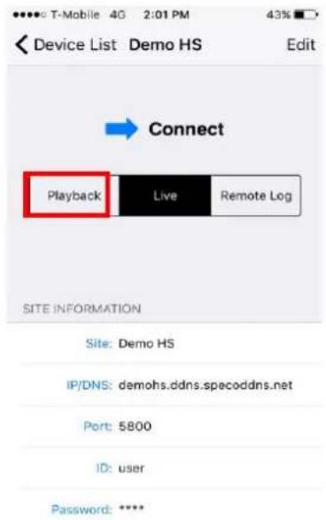
text_image
Device List Demo HS Edit Connect Playback Live Remote Log SITE INFORMATION Site: Demo HS IP/DNS: demohs.ddns.specoddns.net Port: 5800 ID: user Password: ****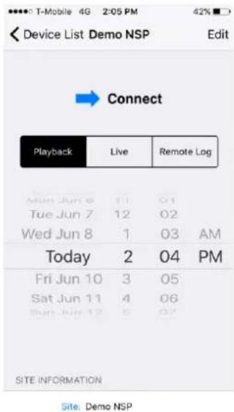
text_image
Device List Demo NSP Edit Playback Live Remote Log Mon Jun 6 11 01 Tue Jun 7 12 02 Wed Jun 8 1 03 AM Today 2 04 PM Fri Jun 10 3 05 Sat Jun 11 4 06 Sun Jun 12 5 07 SITE INFORMATION Site: Demo NSP- The app will display the selected channel(s). Double tap the channel screen to switch 1 channel display to 4, 8, 10, 16 channels split display depending on the DVR.
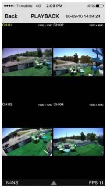
text_image
Back PLAYBACK 06-09-16 14:04:24 CH 01 1930 x 1080 CH 02 1930 x 1080 CH 03 1920 x 1080 CH 04 1920 x 1080 N4NS FPS 11

natural_image
Outdoor scene with green chairs on a rooftop, parked cars, and a building in the background (no visible text or symbols)- Tap the menu button. Then Playback menu icons will display.

text_image
Back PLAYBACK 06-09-16 14:04:30 N4NS EPS 309-2. App Viewer for Android Phone
- Enter the Android Play Store.

- Search "Speco Player" in the Android Market and install the "Speco Player" app.

Notice
SPECO Player is for the VT, HT, NS, HS, DS, RS, WRS and HD series DVRs. SPECO VIEWER is not compatible with the T Series DVR's (TH, TN or TL) or the PC Series
9-2-1. Live
- Open the installed "Speco Player" App and select the "Live view / Playback". Then click the menu button of the phone to add a remote device.
- Select the registered device and select 'Live view' and select up to 4 channels to monitor. Then click 'Start' button.

text_image
speco player Main menu Live Video / Playback Screenboard Video Speco Player speco technologies
text_image
Demo NSP Demo HS
text_image
Device Name Demo MSP Address demo:spodtns.net Port STDG User Name user Password --- Mode type Live view Select Channel Select Channels 1 2 3 4 5 6 7 8 9 10 11 12 13 14 15 16 10 minutes listen, exits, Start- The app will display the selected channel(s). Double tap the channel screen to switch 1 channel display to 4 channels split display.

natural_image
Four-panel surveillance camera grid showing outdoor scenes with buildings and greenery, plus a zoom interface panel at bottom (no readable text or symbols)9-2-2. Playback
- Select the registered device and select 'Play back' and select up to 4 channels to search. Then click 'Start' button. As soon as setting the date and time to search, the app will start the playback.
text_image
Device Name: Demo HSP Address: durnupsp.odms.spocodins.net Port: 5700 User Name: user Postbound: **** Mode type: Play back Select Channel: Select Channels 1 2 3 4 5 6 7 8 9 10 11 12 33 34 35 36 30 minutes later: exit. Start
text_image
Device Name: Devio HGP Address: dsmnq.sdsn.splucrdns.net Port: SEDD User Name: user Preload: — Mode type: Pcs (p)XP Select Channel: All Channels Set Date + + + Jun 09 2016 — — — OK Cancel
text_image
Device Name: Denny 10SF Address: denny.10SF@csscplc.net Port: 5736 User Name: User Pocounts: ... Particle type: Play Back Select Channel: Select Channels Set Time + + 1 02 PM - - On Cancel Start- The app will display the selected channel(s). Double tap the channel screen to switch 1 channel display to 4 channels split display.

text_image
DH-1 37:00:00:00 DH-2 7:00:00:00 DH-3 16:00:00:00 DH-4 16:00:00:00 14:00 PPB : 20 06:09 13:59:30 32x 8x 8x 32x9-2-3.PTZ Control
To control the PTZ function of the camera, tap the channel screen, and then the channel name will be highlighted in Light Green. Using the PTZ menu icons on the screen, control PTZF.
text_image
CH-1 *04w480 CH-2 *04w480 CH-3 *04w480 CH-4 *04w480 F19: 30 06/09 18:45:19 PTZ FOCUS ZOOM
text_image
MNS FPS: 30 06/09 18:46:19 PTZ FOCUS ZOOMAPPENDIX: Network Connection - LAN

text_image
FE CE CAUTION XEO IN CYBE OUT VGA AUDIO OUT USB M F C D S POWER LaptopIP Router or HUB
- Install the network client software from the supplied CD.
- Check the IP address from SETUP > SYSTEM > DESCRIPTION or SETUP > NETWORK of DVR.
text_image
Model Name D4VT Software Version Ver 5.2.1_20160728 Storage Size 1740 GB Network Type Dhcp IP Address 172.16.2.17 MAC Address 00:00:23:34:45:66 DDNS Status DDNS Off Unit Name DVR Remote Controller ID 0 ok- Run the network client software.
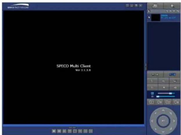
text_image
SPECO Multi Client Ver 3.1.3.8
text_image
Site Addition Site Info Site name: D16VS Site address: 172.16.2.57 Port number: 5445 ID: admin Password: ****. OK Cancel-
Input Site Name, Site Address (IP address), Port Number, and Password on the connect window.
-
Site Name: Input a name that properly describes a site.
• IP Address: Input IP address - Port Number: Default Port Number is "5445".
• ID: Input ID of DVR. Default ID is "admin".
- Password: Input network password of DVR. Default Password is "1111".
- Select a site by checking the box, and Press

button to connect to the site.
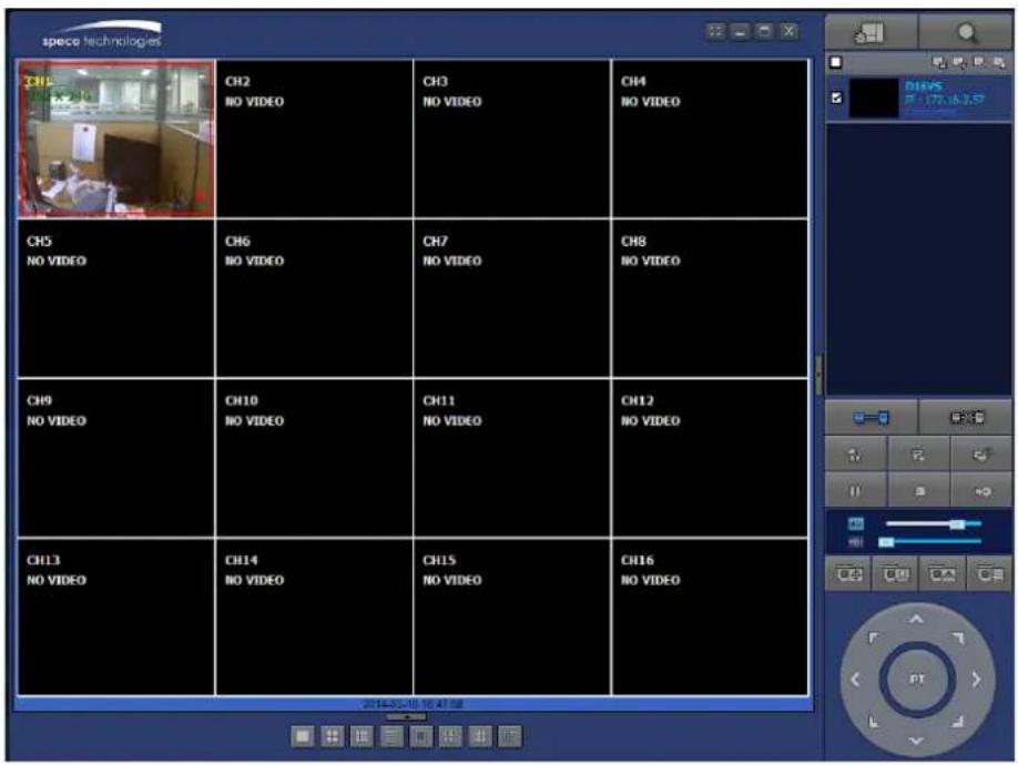
APPENDIX: Network Connection – Internet and DDNS
Dynamic Domain Name System (DDNS) allows a domain name to be constantly synchronized with a dynamic IP address. A current dynamic IP address is being associated with a static domain name.
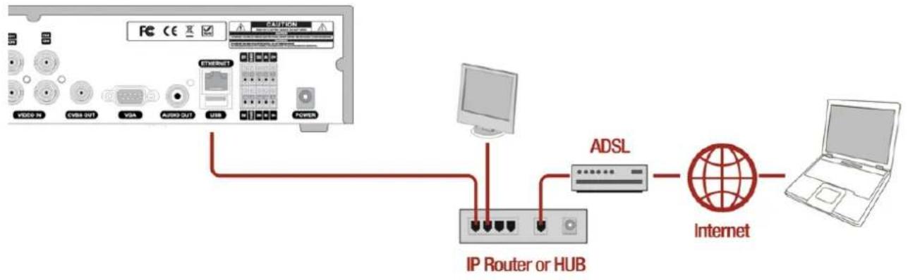
flowchart
graph TD
    A["Router"] -->|VISA OUT| B["Internet"]
    A -->|VISA| C["ADSL"]
    A -->|AUDIO| D["Network Interface"]
    A -->|USB| E["Computer"]
    A -->|POWER| F["Laptop"]
- Go to SETUP>NETWORK>DDNS and set the DDNS SERVER to ON.
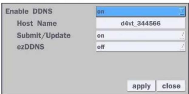
text_image
Enable DDNS Host Name d4vt_344566 Submit/Update on ezDDNS off apply closeIf you set ezDDNS to ON, the host name is automatically generated and registered.
- Go to SETUP>NETWORK>DDNS>HOST NAME. Manually enter a domain name using the virtual keyboard and click ENTER button.

text_image
Password ` 1 2 3 4 5 6 7 8 9 0 - = ← q w e r t y u i o p [ ] Caps a s d f g h j k l ; ' Enter Shift z x c v b n m , . / Shift Clear Space Close- When a manual host name is completed, Go to SETUP>NETWORK>DDNS>SUBMIT/UPDATE and select ON to submit the settings on the SPECO DDNS.
Once the setting is completed, the DDNS address will be:
http://hostname.ddns.specoddns.net
For example, if you enter the host name as "D16VT", then the address will be:
http://d16VT.ddns.specoddns.net
- When DDNS setting is done, click the APPLY button. Otherwise DDNS setting will not be applied.
- When you exit SETUP menu, DDNS NOTIFY window will pop up.
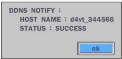
text_image
DDNS NOTIFY : HOST NAME : d4vt_344566 STATUS : SUCCESS ok- DDNS registration status can be checked from SYSTEM INFORMATION or SETUP>SYSTEM>DESCRIPTION>DDNS STATUS
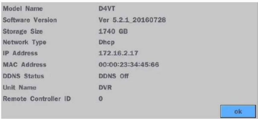
text_image
Model Name D4VT Software Version Ver 5.2.1_20160728 Storage Size 1740 GB Network Type Dhcp IP Address 172.16.2.17 MAC Address 00:00:23:34:45:66 DDNS Status DDNS Off Unit Name DVR Remote Controller ID 0 ok- Check the NETWORK PORT (Default: 5445), WEB PORT (Default: 80), and the IP Address of the DVR from SETUP>NETWORK.

text_image
Network Network Type IP Subnet Mask Gateway DNS (Primary) DNS (Secondary) DDNS Network Video Port Network Audio Port Web Port Network Stream Wireless LAN Push Event dhcp 172.16.2.17 255.255.0.0 172.16.1.254 168.126.63.1 168.126.63.2 select 5445 5446 80 443 select off select select apply cancel- Port forward the NETWORK PORT (Default: 5445) and WEB PORT (Default: 80) of the private IP Address of the DVR on the network router.

Please refer to the user manual and guide for the detailed steps for port forwarding for specific router model.
- Run the network client software.
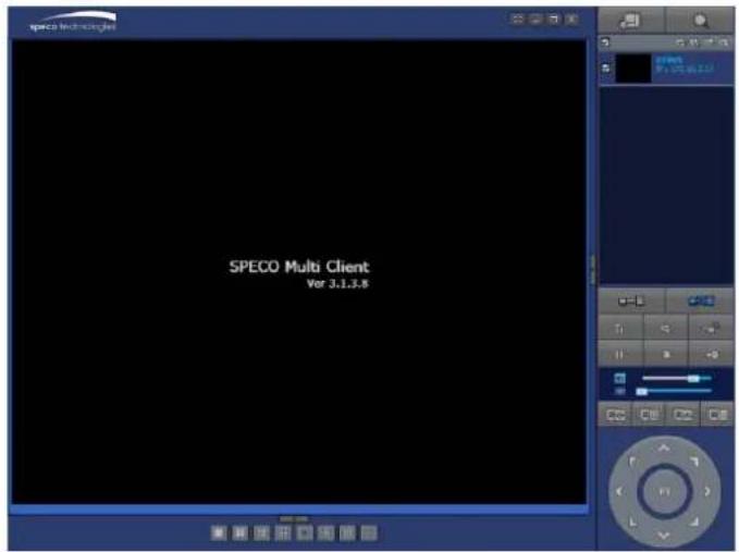
text_image
SPECO Multi Client Ver 3.1.3.8
text_image
Site Addition Site Info Site name: D16VS Site address: 172.16.2.57 Port number: 5445 ID: admin Password: ****. OK Cancel-
Input Site Name, Site Address (IP address), Port No., and Password on the connect window.
-
Site Name: Input a name that properly describes a site.
• IP Address: Domain name or Public IP address of a router that DVR is connected. - Port Number: Default Port Number is "5445".
• ID: Input ID of DVR. Default ID is "admin". -
Password: Input network password of DVR. Default Password is "1111".
-
And select the OK button. Then, press

button after checking the left check box.