A5201HYG - Humidifier JUNG - Free user manual and instructions
Find the device manual for free A5201HYG JUNG in PDF.

User questions about A5201HYG JUNG
0 question about this device. Answer the ones you know or ask your own.
Ask a new question about this device
Download the instructions for your Humidifier in PDF format for free! Find your manual A5201HYG - JUNG and take your electronic device back in hand. On this page are published all the documents necessary for the use of your device. A5201HYG by JUNG.
USER MANUAL A5201HYG JUNG
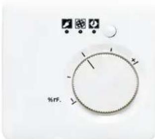
Operating Instructions Hygrostat
text_image
%FF.Table of contents
- Safety instructions....2
- Device layout 2
- Function 2
3.1. Designated use 2
3.2. Product features.... 3
3.3. Automatic mode....3
3.4. Manual mode 3
3.5. Party mode.... 3
3.6. Standby mode.... 3
- Operation....4
4.1. Setting the humidity manually.... 4
4.2. Dehumidifying the ambient air manually.... 4
4.3. Activating the party mode 4
4.4. Activating the standby mode....4
4.5. Switching back to automatic mode 5
4.6. Cleaning the hygrostat....5
- Fitting and electrical connection.... 5
5.1. Fitting and connecting the device 5
- Annex......7
6.1. Technical data....7
6.2. Help in case of trouble 7
6.3. Guarantee....7
1. Safety instructions
Electrical equipment must be installed and fitted by qualified electricians only.
Before working on the device, disconnect the supply voltage (by cutting out the circuit breaker) to avoid the risk of an electric shock. Failure to observe the instructions may cause damage to the device and result in fire or other hazards.
In rooms with open fires such as fireplaces or gas cookers, room ventilation systems may only be operated if additional protective measures are taken. The applicable Building Regulations for hearth and fireplace installations must be observed.
These operating instructions are part of the product and must be left with the final customer.
2. Device layout
text_image
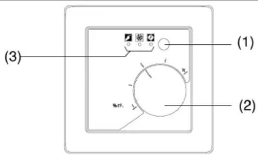
(1) (2) (3)Fig 1: Front view
(1) Mode-of-operation selector
(2) Control knob
(3) Status LED
3. Function
3.1. Designated use
The hygrostat controls the humidity of the air in order to create agreeable and healthy conditions in the room and helps to prevent the formation of detrimental mould.
• Measurement of air humidity in rooms
• Control of 230 V heating and ventilation appliances
• Installation in a flush-mounting box in acc. with DIN 49073
3.2. Product features
- Measurement of room temperature and air humidity to determine the optimal content of moisture in the air
- Control of heating and ventilation appliances for the removal of moisture in rooms
- Manual control range approx. 20...95 % or fixed value of 60 % relative humidity
- Control knob for manual adjustment of the setpoint
- Modes of operation: automatic, manual, party, standby
- Status LED
• Time-controlled continuous operation
3.3. Automatic mode
When the air humidity exceeds the preset value, the hygrostat activates the connected dehumidification appliance:
• LED 🎨 yellow: off, LED 🎨 green: on, LED 🎨 red: off
When the air humidity is lower than the preset value, the hygrostat deactivates the connected appliance:
• LED 🎨 yellow: off, LED 🎨 green: off, LED 🎨 red: off
After one hour of continuous operation, the hygrostat switches off the appliance for 4 hours:
• LED 🎨 yellow: off, LED 🎨 green: off, LED 🎨 red: on
① If the content of water in the ambient air is very high, a dehumidification by means of a fan is not possible.
3.4. Manual mode
Fan operation is activated manually for abt. one hour.
• LED 📋 yellow: on, LED 📍 green: on, LED 📍 red: off
3.5. Party mode
Fan operation is activated manually for abt. six hours.
• LED 🎨 yellow: on, LED 🎨 green: on, LED 🎨 red: flashing
3.6. Standby mode
Fan operation is deactivated manually for abt. four hours.
• LED 📋 yellow: on, LED 🌐 green: off, LED 🏠 red: on
4. Operation
4.1. Setting the humidity manually
The center position of the control knob corresponds to approx. 55 % relative humidity, which is generally considered just right for comfort.
The device must be in the automatic mode of operation.
The device has been enabled for free selection of the humidity with the control knob (Fig. 3)
- To increase the air humidity: turn the control knob to the right.
- To reduce the air humidity: turn the control knob to the left.
When making changes, proceed only in small steps until the setting for individual comfort has been found. As the air conditions in the room change only slowly, the time between changes should be at least 1.5 hours.
① The relative humidity for comfortable room air conditions lies between 40 and 60 %.
4.2. Dehumidifying the ambient air manually
The device must be in the automatic mode of operation.
- Depress the mode-of-operation selector briefly.
The relay is switched on for abt. one hour independent of the degree of humidity in the room.
LED 📋 yellow: on, LED 🌐 green: on, LED 🏠 red: off
After an hour, the hygrostat switches back to the automatic mode of operation.
4.3. Activating the party mode
The device must be in the automatic or in the manual mode of operation.
- Depress the mode-of-operation selector twice briefly.
The relay is switched on for abt. six hours independent of the degree of humidity in the room.
LED 📋 yellow: on, LED 🌐 green: on, LED 🏠 red: flashing
At the end of six hours, the hygrostat switches back to the automatic mode of operation.
4.4. Activating the standby mode
The device must be in the automatic mode of operation.
- Press the mode-of-operation selector longer.
After 3 s, the hygrostat switches the relay off for abt. 4 hours independent of the degree of humidity in the room.
LED 📋 yellow: on, LED 🌐 green: off, LED 🏠 red: on
At the end of four hours, the hygrostat switches back to the automatic mode of operation.
4.5. Switching back to automatic mode
- Press the mode-of-operation selector longer.
After abt. 5 s, the hygrostat switches back to the automatic mode of operation.
LED 📋 yellow: off, LED 🌐 green: off, LED 🏠 red: off
① When the relay is switched on in the automatic mode, the green LED
is on.
4.6. Cleaning the hygrostat
Clean the hygrostat housing with a wet cloth.
① Do not use detergents.
① After cleaning, the hygrostat may temporarily measure higher humidity values.
Information for qualified electricians

DANGER!
Electric shock in case of accidental contact with live parts. Electric shocks can be fatal.
Before working on the device, cut out the mains supply and cover up live parts in the surroundings.
5. Fitting and electrical connection
5.1. Fitting and connecting the device
The device consists of the insert and the attachment module (Fig. 4).
text_image
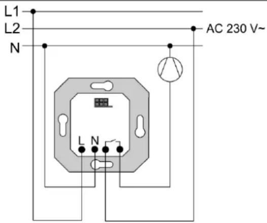
L1 L2 N AC 230 V~ L NFig. 2: Electrical connection
Do not install the hygrostat together with other electrical devices in the same combination since the heat produced by these devices may have an influence on the temperature measurement of the hygrostat.
Temperature Management Hygrostat
Ref.-no.:
Install the hygrostat in a place shielded from direct sunlight, draughts and heat radiation from nearby electrical appliances as, for instance, cooking ranges or refrigerators.
Do not install the hygrostat above or in the vicinity of heating appliances. If possible, install the hygrostat only on a base behaving neutrally in the presence of moisture. Hygroscopic material like plasterboard can influence the control characteristics.
For installation installation in bathrooms, laundry rooms, etc.: observe the safety distances in acc. with IEC 60364-7-701.
Fitting height: approx. 1.5 m
Installation in a flush-mounting box in acc. with DIN 49073.
- Connect the insert (Fig. 2).
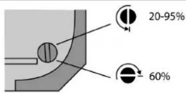
- To set a fixed humidity value: turn the setscrew on the rear of the attachment module to 60% (Fig. 3).
- To activate the control knob function: turn the setscrew on the rear of the attachment module fully to the left to 20-95 % (Fig. 3).
text_image
20-95% 60%Fig. 3: Setscrew for setpoint selection
- Place the decorative frame on the insert.
- Plug the attachment onto the insert observing the correct position (Fig. 4).
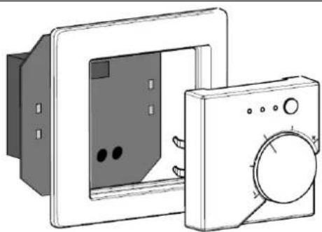
natural_image
Technical line drawing of two electronic components: a front panel with internal slots and a side-mounted device (no text or symbols)Fig. 4: Fitting of the attachment
6. Annex
6.1. Technical data
Rated voltage AC 230 V \~
Mains frequency 50 / 60 Hz
Ambient temperature 0 ... 45 °C
Storage temperature -20 ... 70 °C
Relay contact potential-free n.o. contact
Contact type μ
Switching voltage AC max. 230 V
Switched current AC1 (cos φ > 0,8) 15 mA ... 8 A
Switched current AC3 (cos φ < 0,8) 15 mA ... 4 A
Motors 15 mA ... 4 A
Switching voltage DC max. 24 V
Switched current DC 15 mA ... 8 A
Control range 20 ... 95 % relative humidity (rh)
Measurement tolerance ± 5 % rh
Switching difference
Length of load line ( > 1.5 mm^2 )
± 2 %
max. 100 m
6.2. Help in case of trouble
No function, all LED's blinking
Device installed on wrong insert, e.g. blind/shutter insert.
Install the device on a suitable insert.
6.3. Guarantee
Our products are under guarantee within the scope of the statutory provisions.
Please return the unit postage paid to our central service department giving a brief description of the fault:
ALBRECHT JUNG GMBH & CO. KG
Service-Center
Kupferstr. 17-19
D-44532 Lünen
Service-Line: +(49) 23 55 . 80 65 51
Telefax: +(49) 23 55 . 80 61 65
CE The CE-Sign is a free trade sign addressed exclusively to the authorities and does not include any warranty of any properties.
