EMC1833 - Electronic component Microchip - Free user manual and instructions
Find the device manual for free EMC1833 Microchip in PDF.

User questions about EMC1833 Microchip
0 question about this device. Answer the ones you know or ask your own.
Ask a new question about this device
Download the instructions for your Electronic component in PDF format for free! Find your manual EMC1833 - Microchip and take your electronic device back in hand. On this page are published all the documents necessary for the use of your device. EMC1833 by Microchip.
USER MANUAL EMC1833 Microchip
Note the following details of the code protection feature on Microchip devices:
• Microchip products meet the specification contained in their particular Microchip Data Sheet.
- Microchip believes that its family of products is one of the most secure families of its kind on the market today, when used in the intended manner and under normal conditions.
- There are dishonest and possibly illegal methods used to breach the code protection feature. All of these methods, to our knowledge, require using the Microchip products in a manner outside the operating specifications contained in Microchip's Data Sheets. Most likely, the person doing so is engaged in theft of intellectual property.
• Microchip is willing to work with the customer who is concerned about the integrity of their code.
- Neither Microchip nor any other semiconductor manufacturer can guarantee the security of their code. Code protection does not mean that we are guaranteeing the product as "unbreakable."
Code protection is constantly evolving. We at Microchip are committed to continuously improving the code protection features of our products. Attempts to break Microchip's code protection feature may be a violation of the Digital Millennium Copyright Act. If such acts allow unauthorized access to your software or other copyrighted work, you may have a right to sue for relief under that Act.
Information contained in this publication regarding device applications and the like is provided only for your convenience and may be superseded by updates. It is your responsibility to ensure that your application meets with your specifications. MICROCHIP MAKES NO REPRESENTATIONS OR WARRANTIES OF ANY KIND WHETHER EXPRESS OR IMPLIED, WRITTEN OR ORAL, STATUTORY OR OTHERWISE, RELATED TO THE INFORMATION, INCLUDING BUT NOT LIMITED TO ITS CONDITION, QUALITY, PERFORMANCE, MERCHANTABILITY OR FITNESS FOR PURPOSE. Microchip disclaims all liability arising from this information and its use. Use of Microchip devices in life support and/or safety applications is entirely at the buyer's risk, and the buyer agrees to defend, indemnify and hold harmless Microchip from any and all damages, claims, suits, or expenses resulting from such use. No licenses are conveyed, implicitly or otherwise, under any Microchip intellectual property rights unless otherwise stated.
Microchip received ISO/TS-16949:2009 certification for its worldwide headquarters, design and wafer fabrication facilities in Chandler and Tempe, Arizona; Gresham, Oregon and design centers in California and India. The Company's quality system processes and procedures are for its PIC® MCUs and dsPIC® DSCs, KEELOQ® code hopping devices, Serial EEPROMs, microperipherals, nonvolatile memory and analog products. In addition, Microchip's quality system for the design and manufacture of development systems is ISO 9001:2000 certified.
QUALITY MANAGEMENT SYSTEM CERTIFIED BY DNV = ISO/TS 16949=
Trademarks
The Microchip name and logo, the Microchip logo, AnyRate, AVR, AVR logo, AVR Freaks, BeaconThings, BitCloud, CryptoMemory, CryptoRF, dsPIC, FlashFlex, flexPWR, Heldo, JukeBlox, KEELOQ, KEELOQ logo, Kleer, LANCheck, LINK MD, maXStylus, maXTouch, MediaLB, megaAVR, MOST, MOST logo, MPLAB, OptoLyzer, PIC, picoPower, PICSTART, PIC32 logo, Prochip Designer, QTouch, RightTouch, SAM-BA, SpyNIC, SST, SST Logo, SuperFlash, tinyAVR, UNI/O, and XMEGA are registered trademarks of Microchip Technology Incorporated in the U.S.A. and other countries.
ClockWorks, The Embedded Control Solutions Company, EtherSynch, Hyper Speed Control, HyperLight Load, IntelliMOS, mTouch, Precision Edge, and Quiet-Wire are registered trademarks of Microchip Technology Incorporated in the U.S.A. Adjacent Key Suppression, AKS, Analog-for-the-Digital Age, Any Capacitor, AnyIn, AnyOut, BodyCom, chipKIT, chipKIT logo, CodeGuard, CryptoAuthentication, CryptoCompanion, CryptoController, dsPICDEM, dsPICDEM.net, Dynamic Average Matching, DAM, ECAN, EtherGREEN, In-Circuit Serial Programming, ICSP, Inter-Chip Connectivity, JitterBlocker, KleerNet, KleerNet logo, Mindi, MiWi, motorBench, MPASM, MPF, MPLAB Certified logo, MPLIB, MPLINK, MultiTRAK, NetDetach, Omniscient Code Generation, PICDEM, PICDEM.net, PICkit, PICtail, PureSilicon, QMatrix, RightTouch logo, REAL ICE, Ripple Blocker, SAM-ICE, Serial Quad I/O, SMART-I.S., SQI, SuperSwitcher, SuperSwitcher II, Total Endurance, TSHARC, USBCheck, VariSense, ViewSpan, WiperLock, Wireless DNA, and ZENA are trademarks of Microchip Technology Incorporated in the U.S.A. and other countries.
SQTP is a service mark of Microchip Technology Incorporated in the U.S.A.
Silicon Storage Technology is a registered trademark of Microchip Technology Inc. in other countries.
GestIC is a registered trademark of Microchip Technology Germany II GmbH & Co. KG, a subsidiary of Microchip Technology Inc., in other countries.
All other trademarks mentioned herein are property of their respective companies.
© 2017, Microchip Technology Incorporated, All Rights Reserved.
ISBN: 978-1-5224-2696-7
Table of Contents
Preface 5
Introduction....5
Document Layout 5
Conventions Used in this Guide 6
Recommended Reading....7
The Microchip Website....7
Product Change Notification Service....7
Customer Support 7
Document Revision History 7
Chapter 1. Product Overview
1.1 Introduction 9
1.2 EMC1833 Device Overview 9
1.3 EMC1833 Evaluation Board Overview 9
1.4 Evaluation Board Kit Contents 10
Chapter 2. Installation and Operation
2.1 Getting Started 11
2.2 System and Configuration Requirements 11
2.3 Board Setup 11
2.4 Software Setup 13
Chapter 3. Software GUI Description
3.1 Thermal Management Utility Software GUI Overview 17
3.2 Real-Time Acquisition Action Buttons 18
3.3 Temperatures, Sensor Settings and Registers List tabs 19
3.4 Data Acquisition Charting Area 23
Appendix A. Schematic and Layouts
A.1 Introduction 30
A.2 ADM00773 Board – Schematic 31
A.3 ADM00773 Board – Schematic 2 32
A.4 Board – Top Silk 33
A.5 Board – Top Copper and Silk 33
A.6 Board – Top Copper 34
A.7 Board – Bottom Copper 34
A.8 Board – Bottom Copper and Silk 35
A.9 Board – Bottom silk 35
Appendix B. Bill of Materials (BOM) 36
Worldwide Sales and Service 38
Preface
NOTICE TO CUSTOMERS
All documentation becomes dated, and this manual is no exception. Microchip tools and documentation are constantly evolving to meet customer needs, so some actual dialogs and/or tool descriptions may differ from those in this document. Please refer to our website (www.microchip.com) to obtain the latest documentation available.
Documents are identified with a "DS" number. This number is located on the bottom of each page, in front of the page number. The numbering convention for the DS number is "DSXXXXXXXXA", where "XXXXXXXXX" is the document number and "A" is the revision level of the document.
For the most up-to-date information on development tools, see the MPLAB ^® IDE online help. Select the Help menu, and then Topics to open a list of available online help files.
INTRODUCTION
This chapter contains general information that will be useful to know before using the EMC1833 Evaluation Board User's Guide. Items discussed in this chapter include:
- Document Layout
- Conventions Used in this Guide
• Recommended Reading
• The Microchip Website
• Product Change Notification Service - Customer Support
• Document Revision History
DOCUMENT LAYOUT
This document describes how to use the EMC1833 Evaluation Board User's Guide as a development tool to emulate and debug firmware on a target board. The manual layout is as follows:
- Chapter 1. “Product Overview” – Important information about the EMC1833 Evaluation Board User’s Guide.
- Chapter 2. “Installation and Operation” – This chapter includes a detailed description of each function of the evaluation board and instructions on how to use the board.
- Chapter 3. “Software GUI Description” – Includes instructions to evaluate the EMC1833 for temperature sensing applications.
- Appendix A. “Schematic and Layouts” – Shows the schematic and layout diagrams for the EMC1833 Evaluation Board User’s Guide.
- Appendix B. “Bill of Materials (BOM)” – Lists the parts used to build the EMC1833 Evaluation Board User’s Guide.
CONVENTIONS USED IN THIS GUIDE
This manual uses the following documentation conventions:
DOCUMENTATION CONVENTIONS
| Description Represents Examples | ||
| Arial font: | ||
| Italic characters Referenced books | Books MPLAB | ^ IDE User's Guide |
| Emphasized text ...is the only compiler... | ||
| Initial caps A window the Output | ut window | |
| A dialog the Settings dialog | ||
| A menu selection select Enable Programmer | ||
| Quotes A field name in a window or dialog | "Save project before build" | |
| Underlined, italic text with right angle bracket | A menu path | File>Save |
| Bold characters | A dialog button | Click OK |
| A tab | Click the Power tab | |
| N'Rnnnn | A number in verilog format, where N is the total number of digits, R is the radix and n is a digit. | 4'b0010, 2'hF1 |
| Text in angle brackets <> | A key on the keyboard | Press,, |
| Courier New font: | ||
| Plain Courier New | Sample source code | #define START |
| Filenames | autoexec.bat | |
| File paths | c:\mccl8\h | |
| Keywords | _asm, _endasm, static | |
| Command-line options | -Opa+, -Opa- | |
| Bit values | 0, 1 | |
| Constants | 0xFF, 'A' | |
| Italic Courier New | A variable argument | file.o, where file can be any valid filename |
| Square brackets [] | Optional arguments | mccl8 [options] file [options] |
| Curly brackets and pipe character: { | } | Choice of mutually exclusive arguments; an OR selection | errorlevel {0|1} |
| Ellipses... | Replaces repeated text | var_name [, var_name...] |
| Represents code supplied by user | void main (void) { ... } | |
RECOMMENDED READING
This user's guide describes how to use the EMC1833 Evaluation Board. Other useful documents are listed below. The following Microchip documents are available and recommended as supplemental reference resources:
EMC1812/13/14/15/33 Data Sheet – “EMC1812/13/14/15/33 DS Multi-Channel Low-Voltage Remote Diode Sensor Family Data Sheet” (DS20005751).
PIC18(L)F2X/45K50 Data Sheet – “28/40/44-Pin, Low-Power, High-Performance Microcontrollers with XLP Technology” (DS30000684).
THE MICROCHIP WEBSITE
Microchip provides online support via our website at www.microchip.com. This website is used as a means to make files and information easily available to customers. Accessible by using your favorite internet browser, the website contains the following information:
- Product Support – Data sheets and errata, application notes and sample programs, design resources, user's guides and hardware support documents, latest software releases and archived software
- General Technical Support – Frequently Asked Questions (FAQs), technical support requests, online discussion groups, Microchip consultant program member listing
- Business of Microchip – Product selector and ordering guides, latest Microchip press releases, listing of seminars and events, listings of Microchip sales offices, distributors and factory representatives
PRODUCT CHANGE NOTIFICATION SERVICE
Microchip's customer notification service helps keep customers current on Microchip products. Subscribers will receive email notifications whenever there are changes, updates, revisions or errata related to a specified product family or development tool of interest.
To register, access the Microchip website at www.microchip.com, click on Product Change Notification and follow the registration instructions.
CUSTOMER SUPPORT
Users of Microchip products can receive assistance through several channels:
• Distributor or Representative
- Local Sales Office
• Field Application Engineer (FAE)
- Technical Support
Customers should contact their distributor, representative or FAE for support. Local sales offices are also available to help customers. A listing of sales offices and locations is included in the back of this document.
Technical support is available through the website at: http://www.microchip.com/support
DOCUMENT REVISION HISTORY
Revision A (February 2018)
- Initial release of this document.
NOTES:
Chapter 1. Product Overview
1.1 INTRODUCTION
This chapter provides an overview of the EMC1833 Evaluation Board:
• What is the EMC1833 Device?
• What is the EMC1833 Evaluation Board?
• What the EMC1833 Evaluation Board Kit Contains
1.2 EMC1833 DEVICE OVERVIEW
The EMC1833 Evaluation Board is used to evaluate the EMC18XX family of remote diode temperature monitors. Users can now easily evaluate many of the integrated features of the EMC18XX device family. The device also has a on-board connector configured for an anti-parallel diode to allow for off-board temperature measurements. In addition, the evaluation board connects to PC through a USB interface. Temperature can be data-logged using the Microchip Thermal Management Software Graphical User Interface (GUI).
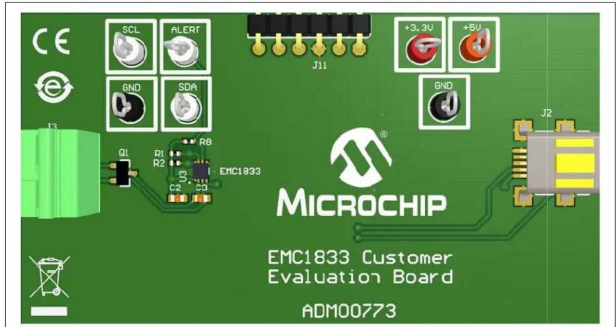
1.3 EMC1833 EVALUATION BOARD OVERVIEW
The board enables users to easily evaluate many custom programmable features such as Rate of Change, Temperature Alert Limit settings, Temperature Conversion Rate, Resistance Error Correction (REC) and Power Modes.
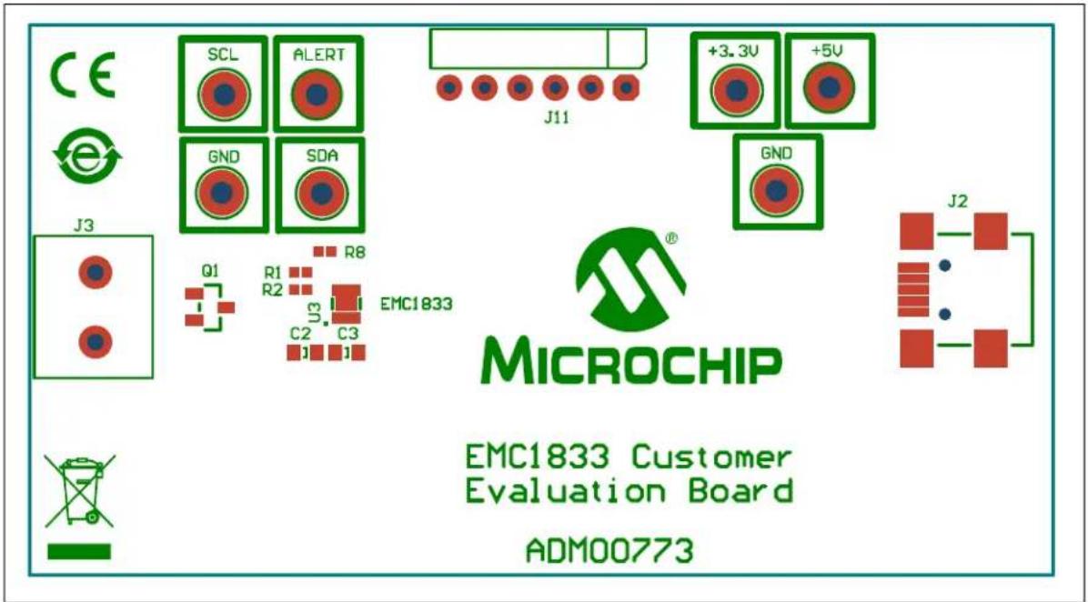
Figure 1-1 shows the top view of the EMC1833 Evaluation Board.
text_image
CE e SCL ALERT J11 +3.3V +5V GND SDA GND J2 MICROCHIP EMC1833 Customer Evaluation Board ADM00773 Q1 R1 R2 R8 EMC1833 C2 C3FIGURE 1-1: EMC1833 Evaluation Board (ADM00773) - Top View.
Figure 1-2 shows the bottom view of the EMC1833 Evaluation Board.

text_image
FB1 C5 U1 SOT-213 C4 R16 C6 C18 R21 C19 U2 U-N-28 X1 C7 R4 LABEL1 04-10567-R2FIGURE 1-2: EMC1833 Evaluation Board (ADM00773) - Bottom View.
1.4 EVALUATION BOARD KIT CONTENTS
The EMC1833 Evaluation Board Kit includes:
• EMC1833 Evaluation Board (ADM00773)
- USB cable
• 2N3904FS-ND transistor (TO-92 package)
- Important Information Sheet
Chapter 2. Installation and Operation
2.1 GETTING STARTED
This section describes how to power-up and interface with the EMC1833 Evaluation Board. Items discussed in this chapter include:
- System and configuration requirements
- The hardware setup required prior to using the evaluation board
• Performing software setup - Operating the device's software interface, the Thermal Management Utility - [EMC1833] GUI.
2.2 SYSTEM AND CONFIGURATION REQUIREMENTS
The EMC1833 Evaluation Board is designed to be used in a Microsoft Windows® XP® (SP3 or later) environment, based on the Microsoft.NETTM Framework 2. Users can utilize the Microsoft .NET Framework 2 web installer package to download and install the .NET Framework components. For USB connectivity, the minimal physical requirement for the PC is a standard USB 2.0 port. In case the board connects to the PC through a USB hub, use a self-powered hub.
2.3 BOARD SETUP
Before the EMC1833 Evaluation Board can be used, a few steps must be performed to install the PC software and configure the board's hardware.
- Download the support material (PC application) that can be found on the ADM00773 board page, at www.microchip.com. Unzip the archive and install the .exe file.
- Connect the collector and base of the transistor to the DP input and the emitter to the DN input. The orientation of the transistor is shown below. Note the transistor is flat side down, as you can observe in Figure 2-1.

text_image
CE SCL ALERT J11 +3.2V +RL GND GND J2 Q1 R1 R2 C2 C3 ENC1833 MICROCHIP EMC1833 Customer Evaluation Board ADM00773FIGURE 2-1: Board Connections.
2.3.1 Hardware Setup and Description
Follow these steps to set up the hardware:
- The board has a mini-USB connector for a PC interface. Connect the USB cable from the evaluation board to a PC.
- Start the Thermal Management Software GUI for temperature data logging or to evaluate the sensor board features.
This evaluation board is fully powered from PC USB source, 5V. Once power is applied via USB, and the USB is successfully enumerated then the PIC ^® microcontroller is ready to receive commands from the host PC to program the EMC1833 settings or transfer temperature data.
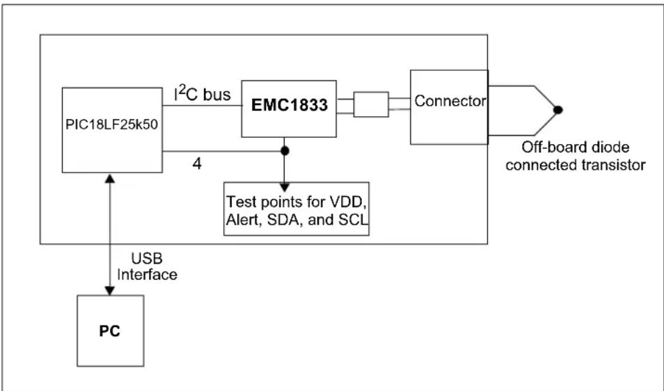
flowchart
graph TD
    A["PIC18LF25k50"] -->|I²C bus| B["EMC1833"]
    B --> C["Connector"]
    C --> D["Off-board diode connected transistor"]
    E["PC"] -->|USB Interface| A
    F["Test points for VDD, Alert, SDA, and SCL"] --> B
FIGURE 2-2: EMC1833 Evaluation Board Circuit Block Diagram.
The block diagram in Figure 2-2 shows that the EMC1833 device is able to monitor and report the ambient temperature of two external diode-connected transistors. One diode is installed on the PCB. A two-pin connector allows the user to connect an additional transistor for evaluation of off-board temperature applications. The Alert outputs, SDA, SCK, and VDD are connected to test points for external connections; in addition, these outputs are also connected to the microcontroller I/O pins so that the Alert Output statuses can be detected in software.
2.4 SOFTWARE SETUP
Follow the installation procedure illustrated below:
- Open the Thermal Management Utility v1.5.5.exe then click Next in the Application Install window.

text_image
Thermal Management Utility v1.5.5 Setup Application Install Welcome to the Setup Wizard for the Thermal Management Utility. < Back Next > CancelFIGURE 2-3: Application Install Dialog Box.
- Read and Accept the License Agreement and click Next.

text_image
Thermal Management Utility v1.5.5 Setup License Agreement Please read the following License Agreement. You must accept the terms of this agreement before continuing with the installation. MICROCHIP SOFTWARE NOTICE AND DISCLAIMER: You may use this software, and any derivatives created by any person or entity by or on your behalf, exclusively with Microchips products. Microchip and its licensors retain all ownership and intellectual property rights in the accompanying software and in all derivatives hereto. Do you accept this license? ● I accept the agreement ○ I do not accept the agreement BitRock Installer < Back Next > CancelFIGURE 2-4: License Agreement Dialog Box.
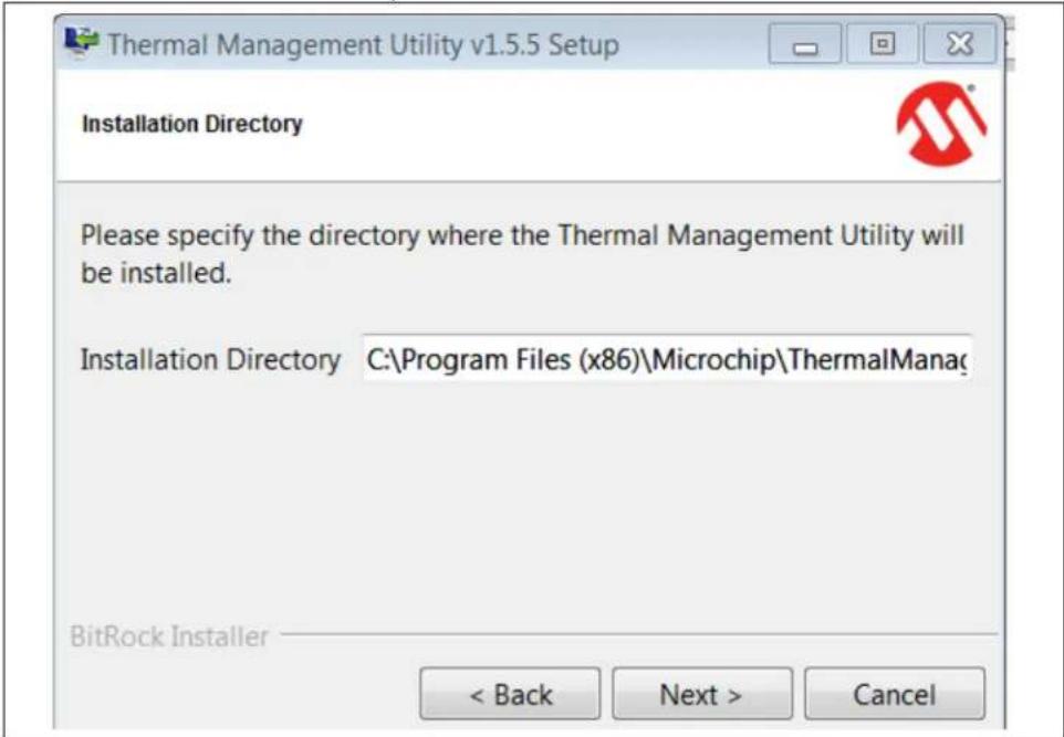
- Select an installation directory and click Next.
text_image
Thermal Management Utility v1.5.5 Setup Installation Directory Please specify the directory where the Thermal Management Utility will be installed. Installation Directory C:\Program Files (x86)\Microchip\ThermalManag BitRock Installer < Back Next > CancelFIGURE 2-5: Installation Directory Dialog Box.
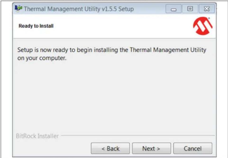
- Select Next to continue with the installation process.
text_image
Thermal Management Utility v1.5.5 Setup Ready to Install Setup is now ready to begin installing the Thermal Management Utility on your computer. BitRock Installer < Back Next > CancelFIGURE 2-6: Ready to Install Dialog Box.
- In the Install Complete dialog box click Finish to finalize installation.

text_image
Thermal Management Utility v1.5.5 Setup Install Complete The Thermal Management Utility has been successfully installed on your computer. ✓ View Release Notes File < Back Finish CancelFIGURE 2-7: Install Complete Dialog Box.
NOTES:
Chapter 3. Software GUI Description
3.1 THERMAL MANAGEMENT UTILITY SOFTWARE GUI OVERVIEW
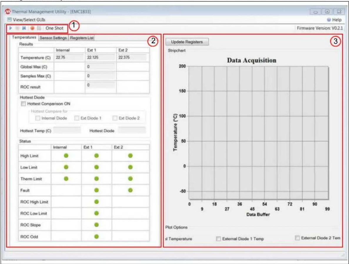
The Microchip Thermal Management Software GUI allows users to evaluate the EMC1833 for temperature sensing applications. Once the hardware is connected, the software recognizes the device ID and displays the corresponding GUI for the evaluation board. Disconnecting the USB will close the GUI. This tool enables users to evaluate the sensor features and perform temperature data-log. Figure 3-1 depicts the Thermal Management Utility GUI.
text_image
Thermal Management Utility - [EMC1833] View/Select GUIs One Shot 1 Temperature Sensor Settings Registers List Results Internal Ext 1 Ext 2 Temperature (C) 22.75 22.125 22.375 Global Max (C) 0 Samples Max (C) 0 ROC result 0 Hottest Diode Hottest Comparison ON Hottest Compare for Internal Diode Ext Diode 1 Ext Diode 2 Hottest Temp (C) Hottest Diode Status Internal Ext 1 Ext 2 High Limit Low Limit Therm Limit Fault ROC High Limit ROC Low Limit ROC Slope ROC Odd Update Registers Stripchart Data Acquisition Temperature (°C) Plot Options il Temperature External Diode 1 Temp External Diode 2 Tem Firmware Version: V0.2.1FIGURE 3-1: Thermal Management Utility GUI.
As displayed in Figure 3-1, the GUI can be divided into three sections:
- One Shot action buttons
- Temperatures, Sensor Settings and Registers List tabs
- Data Acquisition Charting area
3.2 REAL-TIME ACQUISITION ACTION BUTTONS
The Play, Stop, and Reset icons (Figure 3-2) can be used to perform continuous data acquisitions.

flowchart
graph TD
    A["Stop Recording Real-Time acquisition"] --> B["Start/Record Real-Time acquisition"]
    B --> C["Reset Real-Time acquisition"]
    C --> D["Pause Real-Time acquisition"]
    D --> E["Start Real-Time acquisition"]
    E --> F["Start Real-Time acquisition"]
    F --> G["One Shot"]
FIGURE 3-2: Real-Time Acquisition Icons.
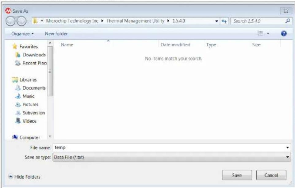
To initiate data logging, click the Record Acquisitions button. The system displays the Save As window (see Figure 3-3), where users need to select a file name and a location, then click the Save button.
text_image
Save As Microchip Technology Inc ▶ Thermal Management Utility ▶ 1.5.4.0 Search 1.5.4.0 Organize ▶ New folder Favorites Downloads Recent Place Libraries Documents Music Pictures Subversion Videos Computer Name Date modified Type Size No items match your search. File name: temp Save as type: Data File (*.txt) Hide Folders Save CancelFIGURE 3-3: Save As Window for Recording Acquisitions.
To stop the data logging click the Stop Recording button. Users can now go to the file location to view the file.
3.3 TEMPERATURES, SENSOR SETTINGS AND REGISTERS LIST TABS
3.3.1 Temperatures Tab
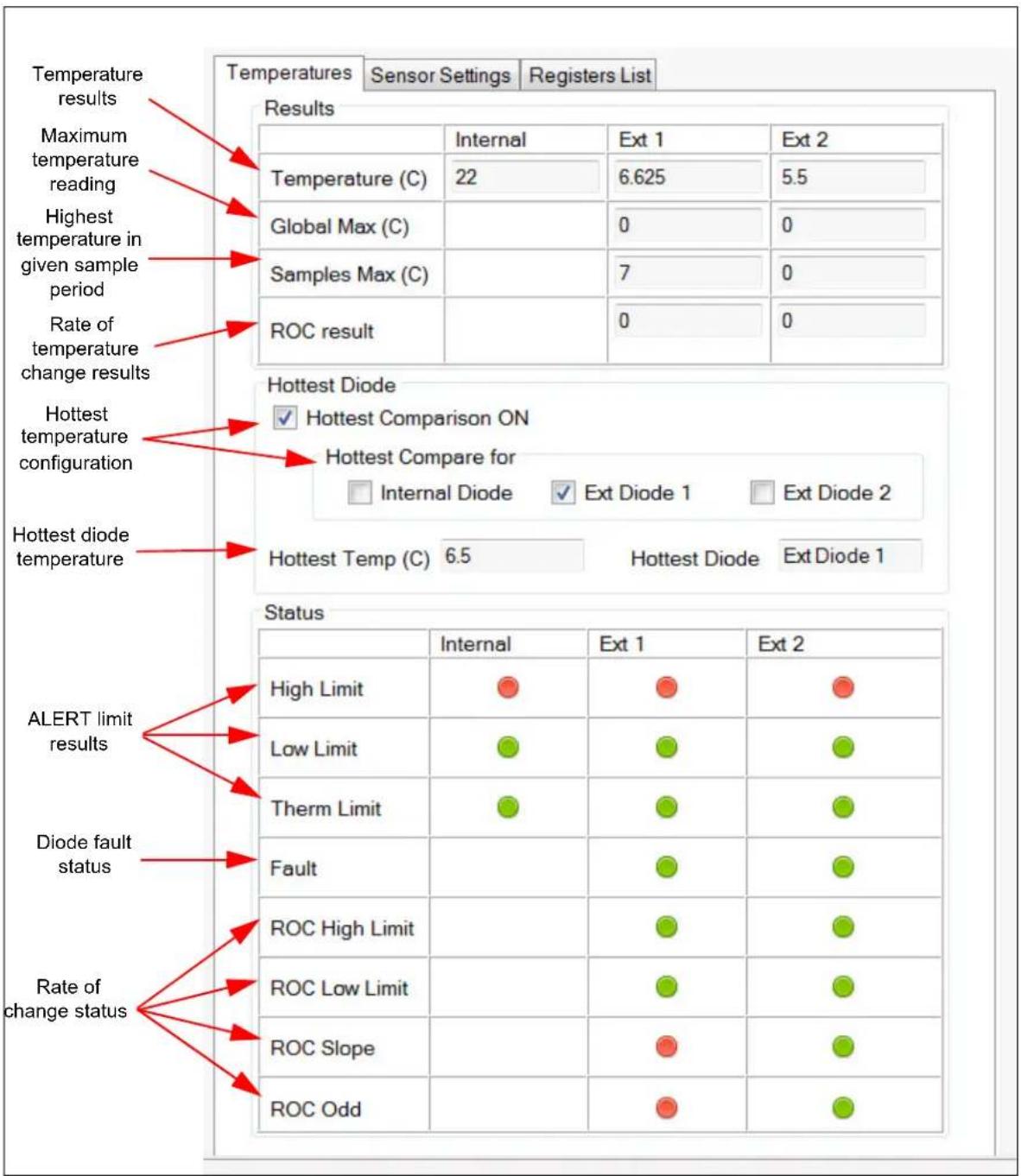
The Temperatures tab displayed in Figure 3-4 shows the results of the Internal Diode 1 and Diode 2 sensors. This tab also displays the result of the various user programmable features of the EMC1833, such as the temperature ALERT and THERM status, Diode Fault status, the Rate of Change (ROC), and hottest diode comparison.
other
| Metric | Internal | Ext 1 | Ext 2 | | :--- | :--- | :--- | :--- | | Temperature (C) | 22 | 6.625 | 5.5 | | Global Max (C) | | 0 | 0 | | Samples Max (C) | | 7 | 0 | | ROC result | | 0 | 0 | | Status | High Limit | Low Limit | Therm Limit | Fault | ROC High Limit | ROC Low Limit | ROC Slope | ROC Odd | |---|---|---|---|---|---|---|---|---| | ALERT limit results | ● | ● | ● | ● | ● | ● | ● | ● | | Diode fault status | ● | ● | ● | ● | ● | ● | ● | ● | | Rate of change status | ● | ● | ● | ● | ● | ● | ● | ● | The table is a table with three columns: 'Results' (Temperature, 'Maximum temperature reading', 'Highest temperature in given sample period', 'Rate of temperature change results') and 'Status' (Hottest Diode, 'Hottest Comparison ON', 'Hottest Compare for', 'Ext Diode 1', 'Ext Diode 2'). The values are explicitly labeled on the table. The data is presented in a grid format.FIGURE 3-4: Temperatures Tab.
3.3.2 Sensor Settings Tab
The Sensor Settings tab is divided into two sections:
- General Settings
- Rate of Change
Figure 3-5 displays the General Settings section under the Sensor Settings tab. This is where the user configures and enables/disables various features of the device.
Refer to the MCP1812/13/14/15/33 data sheet for detailed information on the operation of these features and settings.

text_image
Temperatures Sensor Settings Registers List Rate of Change General Settings Sensor Settings Select or clear the check boxes to enable and disable features Temperature hysteresis value for ALERT and THERM Dynamic Averaging On Active Mode Run REC D1/D2 On Range (C) 0..127.875 Anti Parallel Diode On Consecutive Alert 1 Therm Hysteresis 10 Consecutive Therm 4 Conversion Rate 4 Limit Settings (C) Internal Ext 1 Ext 2 High 85 85 85 Low 0 0 0 Therm 85 85 85 ALERT limits Set output type as comparator or interrupt Mask the alert signal for all temperature channels and ROC events Mask the alert signal for specific temperature channels Alerts Alert Pin Mode Interrupt Mask All Mask Individual Settings Internal Diode External Diode 1 ROC 1 External Diode 2FIGURE 3-5: Sensor Settings Tab - General Settings.
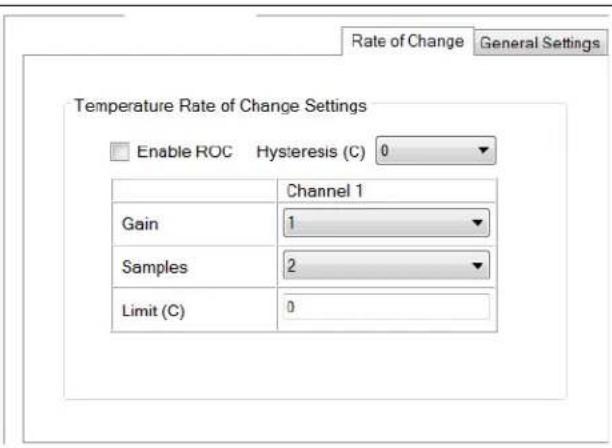
Figure 3-6 displays the Rate of Change (ROC) section under the Sensor Settings tab. This is where the user configures the ROC feature. Refer to the MCP1812/13/14/15/33 data sheet for detailed information regarding the ROC setup and operation.
text_image
Rate of Change General Settings Temperature Rate of Change Settings Enable ROC Hysteresis (C) 0 Channel 1 Gain 1 Samples 2 Limit (C) 0FIGURE 3-6: Rate of Change Tab.
Since the software is constantly polling the status register the status bits are cleared as soon as an out of bounds condition is satisfied when in the Interrupt mode.
A quick way to validate the ROC is utilizing the Standby mode along with the one-shot temperature measurement.
ROC validation example:
- Select Standby mode.
- Set the Gain and Samples drop downs.
- Select the Enable ROC check box.
- Click one-shot.
- Update registers and log temperature for Remote Diode 1.
- Repeat steps 4 and 5 for the samples selected (when all samples have completed the ROC result value will update).
- Calculate the ROC result using Equation 3-1 and compare to the calculated value in the ROC result within the GUI.
EQUATION 3-1:
$$ \frac {\Delta \mathrm{T}}{\Delta \mathrm{t}} \frac {[ \mathrm{T} (\mathrm{t} _ {\max}) - (\mathrm{T}) ] \yen \text {gain}}{\text {sample 1 - (}} $$
Where:
$$ \begin{array}{l} T \left(T _ {T \max}\right) = \text { Temperature at the end of the interval }. \ T (t _ {0}) = \text { Temperature at the beginning of the interval. } \ \end{array} $$
3.3.3 Registers List Tab
The Registers List tab (Figure 3-7) contains a read-only table that contains all the user registers.
| Name | Address High | Address Low | Data High | Data Low |
| Ext1 Temp | 0x01 | 0x10 | 0x16 | 0xC0 |
| Status | - | 0x02 | - | 0x00 |
| Config | - | 0x03 | - | 0x00 |
| Convert | - | 0x04 | - | 0x06 |
| Internal Diode High Limit | - | 0x05 | - | 0x55 |
| Internal Diode Low Limit | - | 0x06 | - | 0x00 |
| Ext1 High Limit | 0x07 | 0x13 | 0x55 | 0x00 |
| Ext1 Low Limit | 0x08 | 0x14 | 0x00 | 0x00 |
| One Shot | - | 0x0F | - | 0x00 |
| Scratchpad1 | - | 0x11 | - | 0x00 |
| Scratchpad2 | - | 0x12 | - | 0x00 |
| Ext2 High Limit | 0x15 | 0x17 | 0x55 | 0x00 |
| Ext2 Low Limit | 0x16 | 0x18 | 0x00 | 0x00 |
| Ext1 Therm Limit | - | 0x19 | - | 0x55 |
| Ext2 Therm Limit | - | 0x1A | - | 0x55 |
| Ext Diode Fault Status | - | 0x1B | - | 0x00 |
| Ext Diode Fault Mask | - | 0x1F | - | 0x00 |
| Internal Therm Limit | - | 0x20 | - | 0x55 |
| Therm Hysteresis | - | 0x21 | - | 0x0A |
| Consecutive Alert | - | 0x22 | - | 0x70 |
| Ext2 Temp | 0x23 | 0x24 | 0x16 | 0x80 |
| Ext1 Ideality | - | 0x27 | - | 0x12 |
| Ext2 Ideality | - | 0x28 | - | 0x12 |
| High Limit Status | - | 0x3A | - | 0x00 |
| Low Limit Status | - | 0x3B | - | 0x00 |
| Therm Limit Status. |
FIGURE 3-7: Registers List Tab.
3.4 DATA ACQUISITION CHARTING AREA
Figure 3-8 shows the data acquisition interface with a plot of the EMC1833 Internal Diode, Diode 1 and Diode 2.

line
| Data Buffer | Internal Temperature (°C) | External Diode 1 Temp (°C) | External Diode 2 Temp (°C) | | ----------- | ------------------------- | -------------------------- | -------------------------- | | 0 | 62 | 93 | 89 | | 9 | 64 | 88 | 87 | | 18 | 68 | 83 | 85 | | 27 | 65 | 89 | 90 | | 36 | 66 | 92 | 91 | | 45 | 67 | 94 | 93 | | 54 | 68 | 95 | 94 | | 63 | 70 | 88 | 89 | | 72 | 71 | 105 | 102 | | 81 | 70 | 102 | 100 | | 90 | 69 | 92 | 91 | | 99 | 68 | 103 | 101 |FIGURE 3-8: Microchip Thermal Management Sensor GUI Data Plot.
The logging interval can be adjusted using the interval scroll bar from 100ms to 30s, as shown in Figure 3-8.
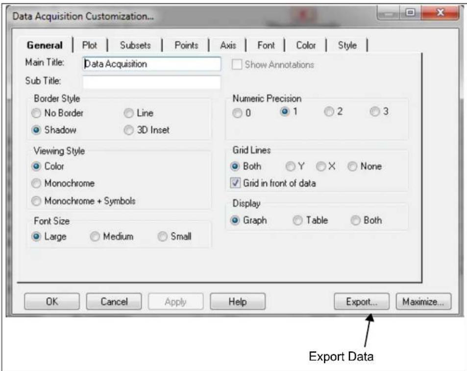
The data acquisition charting area (Figure 3-8) can be customized by double clicking the chart. Performing this action opens the Data Acquisition Customization window, available in Figure 3-9.
Users can also zoom into a specific plot range by clicking and dragging the section. The data in the chart can also be exported using the Export button.
text_image
Data Acquisition Customization... General | Plot | Subsets | Points | Axis | Font | Color | Style | Main Title: Data Acquisition Sub Title: Show Annotations Border Style No Border Line Shadow 3D Inset Viewing Style Color Monochrome Monochrome + Symbols Font Size Large Medium Small Numeric Precision 0 1 2 3 Grid Lines Both Y X None Grid in front of data Display Graph Table Both OK Cancel Apply Help Export... Maximize... Export DataFIGURE 3-9: Data Acquisition Customization Window.
3.4.0.1 DATA ACQUISITION CUSTOMIZATION WINDOW DESCRIPTION
The Data Acquisition Customization window contains eight tabs which contain different options allowing users to customize the data acquisition charting area.
The General tab (Figure 3-9) determines how the data acquisition charting area is displayed. General options include the border style, viewing style, font size, numeric precision and grid lines.
The Display option determines how the data acquisition charting area is generated: a graph, a table, or both.
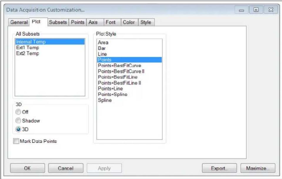
The Plot tab, displayed in Figure 3-10, allows users to customize the appearance of the data sensor plots.
text_image
Data Acquisition Customization... General Plot Subsets Points Axis Font Color Style All Subsets Internal Temp Ext1 Temp Ext2 Temp 3D Off Shadow 3D Mark Data Points Plot Style Area Bar Line Points Points+BestFitCurve Points+BestFitCurve II Points+BestFitLine Points+BestFitLine II Points+Line Points+Spline Spline OK Cancel Apply Export... Maximize...FIGURE 3-10: Data Acquisition Customization - Plot Tab.
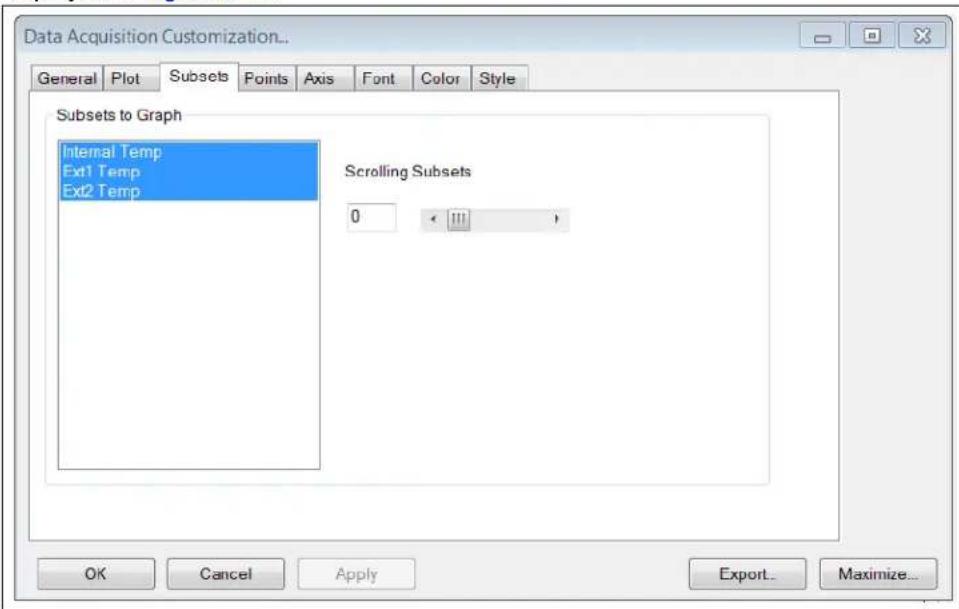
Users can also control the appearance of the subsets plots using the Subsets tab, displayed in Figure 3-11.
text_image
Data Acquisition Customization... General Plot Subsets Points Axis Font Color Style Subsets to Graph Internal Temp Ext1 Temp Ext2 Temp Scrolling Subsets 0 < > OK Cancel Apply Export... Maximize...FIGURE 3-11: Data Acquisition Window - Subsets Tab.
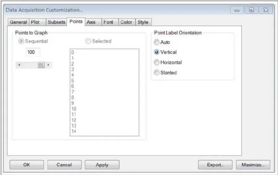
The Points tab, displayed in Figure 3-12, controls the number of data points displayed in the graph and the orientation of the labels on the X-Axis.
text_image
Data Acquisition Customization... General Plot Subsets Points Axis Font Color Style Points to Graph Sequential Selected 100 0 1 2 3 4 5 6 7 8 9 10 11 12 13 14 Point Label Orientation Auto Vertical Horizontal Slanted OK Cancel Apply Export... Maximize...FIGURE 3-12: Data Acquisition Window - Points Tab.
The Axis tab, displayed in Figure 3-13, determines the scale and range of the Y-Axis.

text_image
Data Acquisition Customization... General Plot Subsets Points Axis Font Color Style Y Axis Linear Auto Log Min Max Min/Max Min Max -40.0000 100 OK Cancel Apply Export... Maximize...FIGURE 3-13: Data Acquisition Window - Axis Tab.
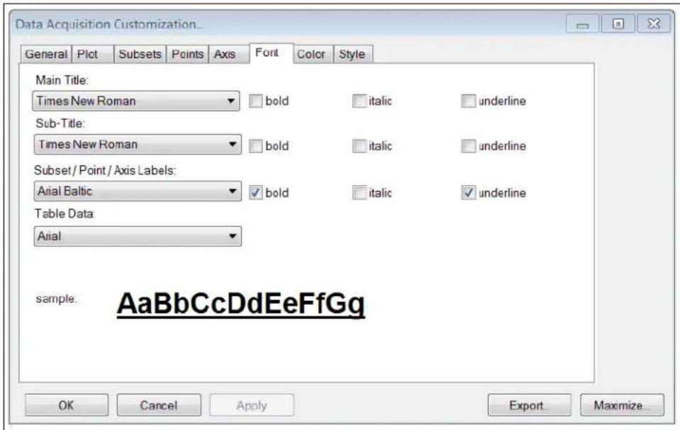
Users can modify the options in the Font tab, displayed in Figure 3-14, to change the size, font and style of the text that appears in the data acquisition charting area. A sample text is also provided for preview before applying the changes to the charting area.
text_image
Data Acquisition Customization... General Plot Subsets Points Axis Font Color Style Main Title: Times New Roman □ bold □ italic □ underline Sub-Title: Times New Roman □ bold □ italic □ underline Subset / Point / Axis Labels: Arial Baltic □ bold □ italic □ underline Table Data: Arial sample: AaBbCcDdEeFfGg OK Cancel Apply ExportMaximize_...FIGURE 3-14: Data Acquisition Window - Font Tab.
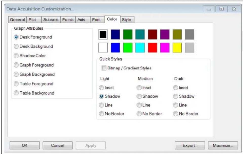
The Color tab, displayed in Figure 3-15, determines which colors are used by the system. Optionally, users can select a preconfigured style in the Quick Styles section.
text_image
Data Acquisition Customization... General Plot Subsets Points Axis Font Color Style Graph Attributes Desk Foreground Desk Background Shadow Color Graph Foreground Graph Background Table Foreground Table Background Quick Styles Bitmap / Gradient Styles Light Medium Dark Inset Inset Inset Shadow Shadow Shadow Line Line Line No Border No Border No Border OK Cancel Apply Export... Maximize...FIGURE 3-15: Data Acquisition Window - Color Tab.
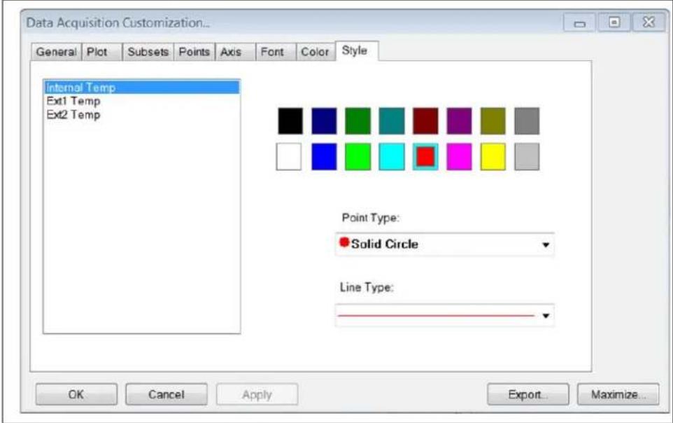
Through the Style tab, displayed in Figure 3-16, users can customize the line style, color, and data point type for each temperature plot.
text_image
Data Acquisition Customization... General Plot Subsets Points Axis Font Color Style Internal Temp Ext1 Temp Ext2 Temp Point Type: Solid Circle Line Type: OK Cancel Apply Export Maximize...FIGURE 3-16: Data Acquisition Window - Style Tab.
NOTES:
Appendix A. Schematic and Layouts
A.1 INTRODUCTION
This appendix contains the following schematics and layouts for the EMC1833 Evaluation Board:
• ADM00773 Board – Schematic
• ADM00773 Board – Schematic 2
- Board – Top Silk
• Board – Top Copper and Silk
- Board – Top Copper
- Board – Bottom Copper
- Board – Bottom Copper and Silk
- Board – Bottom silk
A.2 ADM00773 BOARD - SCHEMATIC

A.3 ADM00773 BOARD - SCHEMATIC 2

text_image
C7 13.2V GND 0.1uF 100V X1 20MHz U2 0805 VDD NCLR/VPP 26 R16 100R 10k R21 +3.3V C18 0.1uF GND RA0/AN0/C1INA/ULPWU/RP0 RC0/T1OSO/TICKI/RP11 8 C402 1% RA1/AN1/C2INA/RP1 RC1/T1OSI/UO/E/RP12 9 RA2/AN2/VREF-/CVREF/C2INB RC2/AN1/C7PLS/RP13 10 RA3/AN3/YREF+/C1INB VUSH 11 VDDCORL/VCAP RC4/D-/VM 12 RA5/AN4/SS1/HLVDIN/RCV/RP2 RC5/D-/VP 13 RA6/OSC2/CLKO RC6/TX1/CKI/RP17 14 RA7/OSC1/CLKI RC7/RX1/DTI/SDOL/RP18 15 VSS R30/AN12/INT0/RP3 16 RB1/AN10/RTCC/RP4 17 RH2/AN8/C1FDI/VMOR/REFOR/P5 18 RB3/AN9/CTED2/VPO/RP6 19 RB4/KBI0/SCKI/SCLI/RP7 20 RB5/KBI1/SDI1/SDA1/RP8 21 RB6/KBI2/PGC/RP9 22 RB7/KBE3/PGD/RP10 23 RDN HDR-2.54 MALE 1x6 J11 GNDA.4 BOARD - TOP SILK
text_image
CE SCL ALERT J11 +3.3V +5V GND SDA GND J3 Q1 R1 R8 EMC1833 J2 R2 U3 C2 C3 EMC1833 MICROCHIP EMC1833 Customer Evaluation Board ADM00773A.5 BOARD – TOP COPPER AND SILK
text_image
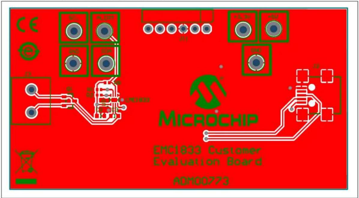
CE MCC ALOR SAD SOP J1 +5.2V +0V SND MICROCHIP EMC1833 Customer Evaluation Board AOM00773A.6 BOARD - TOP COPPER

natural_image
Pure electrical circuit lines without any symbols or text, rendered in red on a white background (no text or labels)A.7 BOARD - BOTTOM COPPER

natural_image
Pure electrical circuit lines without any symbols or text, rendered on a blue background (no readable text or labels)A.8 BOARD - BOTTOM COPPER AND SILK

text_image
PAD4 PAD2 U1 C4 R6 C6 C9 JABEL1 PAD3 04-10567-R2 PAD1A.9 BOARD - BOTTOM SILK

Appendix B. Bill of Materials (BOM)
TABLE B-1: BILL OF MATERIALS (BOM) FOR EMC1833 EVALUATION BOARD (ADM00773) (1)
| Qty. | Reference Description Manufacturer Part Number | |||
| 4 C | 2, C6, C7,C18 | Capacitor Ceramic, 0.1 μF, 100V, 10%,X7R, SMD, 0603 | Murata Electronics NorthAmerica, Inc. | GRM188R72A104KA35D |
| 1 C | 3 Capacitor Ceramic, 1000 pF, 50V, 20%,X7R, SMD, 0603 | KEMET | C0603C102M5RACTU | |
| 2 C | 4, C5 | Capacitor Ceramic, 10 μF, 10V, 10%,X5R, SMD, 0805 | Taiyo Yuden Co., Ltd. | LMK212BJ106KD-T |
| 1 C | 19 | Capacitor Ceramic, 10 μF, 10V, 10%,X5R, SMD, 0805 | Taiyo Yuden Co., Ltd. | LMK212BJ106KG-T |
| 1 FB1 | Ferrite, 2A, 220R, SMD, 0805 | Murata Electronics NorthAmerica, Inc. | BLM21PG221SN1D | |
| 1 J2 | Connector USB mini-B, Female, SMD,R/A | Hirose Electric Co., Ltd. | UX60-MB-5ST | |
| 1 J3 | Connector Term, Block, 5 MM2-Position, GRN | PHOENIX CONTACT | 1792863 | |
| 4 PAD1, PAD2,PAD3, PAD4 | Mechanical HW Rubber PAD,Cylindrical, D7.9, H5.3, Black | 3M | SJ61A11 | |
| 1 PCB1 | Printed Circuit Board - EMC1833 Evalua-tion Board | Microchip TechnologyInc. | 04-10567-R2 | |
| 1 Q1 | Transistor BJT, NPN, 40V, 200 mA,310 mW, SOT-23-3 | Fairchild Semiconductor® | MMBT3904 | |
| 4 R1, R2, R8,R21 | Resistor TKF, 10k, 1%, 1/10W, SMD,0402 | Panasonic® - BSG | ERJ-2RKF1002X | |
| 1 R4 Resistor TKF | 10k, 5%, 1/10W, SMD,0603 | Panasonic® - BSG | ERJ-3GEYJ103V | |
| 1 R16 | Resistor TKF, 100R, 1%, 1/10W, SMD,0402 | Panasonic® - BSG | ERJ-2RKF1000X | |
| 1 TP1 | Connector Test Point, Loop, Orange, TH | Keystone Electronics Corp. | 5013 | |
| 2 TP2, TP7 | Connector Test Point, Loop, Black, TH | Keystone Electronics Corp. | 5011 | |
| 1 TP3 | Connector Test Point, Loop, Red, TH | Keystone Electronics Corp. | 5010 | |
| 3 TP4, TP5,TP6 | Connector Test Point, Loop, White, TH | Keystone Electronics Corp. | 5012 | |
| 1 U1 Microchip Analog LDO, 3.3V, SOT-223-3 | Microchip TechnologyInc. | MCP1825ST-3302E/DB | ||
| 1 U2 Microchip MCU, 8-bit, 48 MHz, 32 kB,2 kB, QFN-28 | Microchip TechnologyInc. | PIC18LF25K50-I/ML | ||
| 1 U3 Three Channel 1.8V, I ^2 C,Temperature Sensor | Microchip TechnologyInc. | EMC1833T-AE/RW | ||
| 1 X1 | DO NOT POPULATE | Murata Electronics NorthAmerica, Inc. | CSTCE20M0V13L99-R0 | |
Note 1: The components listed in this Bill of Materials are representative of the PCB assembly. The released BOM used in manufacturing uses all RoHS-compliant components.
TABLE B-2: BILL OF MATERIALS (BOM) FOR EMC1833 EVALUATION BOARD (ADM00773) - MECHANICAL PARTS ^(1)
| Qty. | Reference Description | Manufacturer Part Number | ||
| 1 | CBL1 Mechanical H | HW, cable USB-A Male to Mini USB-B Male, 3 ft, Black | Qualtek Electronics Corp. 30 | 21003-03 |
| 1 | Q2 Transistor, NPN | 40V, 0.2A, TO-92 Fairchild Semiconductor | ® | 2N3904TA |
Note 1: The components listed in this Bill of Materials are representative of the PCB assembly. The released BOM used in manufacturing uses all RoHS-compliant components.
Worldwide Sales and Service
AMERICAS
Corporate Office
2355 West Chandler Blvd. Chandler, AZ 85224-6199
Tel: 480-792-7200
Fax: 480-792-7277
Technical Support:
http://www.microchip.com/
support
Web Address:
www.microchip.com
Atlanta
Duluth, GA
Tel: 678-957-9614
Fax: 678-957-1455
Austin, TX
Tel: 512-257-3370
Boston
Westborough, MA
Tel: 774-760-0087
Fax: 774-760-0088
Chicago
Itasca, IL
Tel: 630-285-0071
Fax: 630-285-0075
Dallas
Addison, TX
Tel: 972-818-7423
Fax: 972-818-2924
Detroit
Novi, MI
Tel: 248-848-4000
Houston, TX
Tel: 281-894-5983
Indianapolis
Noblesville, IN
Tel: 317-773-8323
Fax: 317-773-5453
Tel: 317-536-2380
Los Angeles
Mission Viejo, CA
Tel: 949-462-9523
Fax: 949-462-9608
Tel: 951-273-7800
Raleigh, NC
Tel: 919-844-7510
New York, NY
Tel: 631-435-6000
San Jose, CA
Tel: 408-735-9110
Tel: 408-436-4270
Canada - Toronto
Tel: 905-695-1980
Fax: 905-695-2078
ASIA/PACIFIC
Australia - Sydney
Tel: 61-2-9868-6733
China - Beijing
Tel: 86-10-8569-7000
China - Chengdu
Tel: 86-28-8665-5511
China - Chongqing
Tel: 86-23-8980-9588
China - Dongguan
Tel: 86-769-8702-9880
China - Guangzhou
Tel: 86-20-8755-8029
China - Hangzhou
Tel: 86-571-8792-8115
China - Hong Kong SAR
Tel: 852-2943-5100
China - Nanjing
Tel: 86-25-8473-2460
China - Qingdao
Tel: 86-532-8502-7355
China - Shanghai
Tel: 86-21-3326-8000
China - Shenyang
Tel: 86-24-2334-2829
China - Shenzhen
Tel: 86-755-8864-2200
China - Suzhou
Tel: 86-186-6233-1526
China - Wuhan
Tel: 86-27-5980-5300
China - Xian
Tel: 86-29-8833-7252
China - Xiamen
Tel: 86-592-2388138
China - Zhuhai
Tel: 86-756-3210040
ASIA/PACIFIC
India - Bangalore
Tel: 91-80-3090-4444
India - New Delhi
Tel: 91-11-4160-8631
India - Pune
Tel: 91-20-4121-0141
Japan - Osaka
Tel: 81-6-6152-7160
Japan - Tokyo
Tel: 81-3-6880-3770
Korea - Daegu
Tel: 82-53-744-4301
Korea - Seoul
Tel: 82-2-554-7200
Malaysia - Kuala Lumpur
Tel: 60-3-7651-7906
Malaysia - Penang
Tel: 60-4-227-8870
Philippines - Manila
Tel: 63-2-634-9065
Singapore
Tel: 65-6334-8870
Taiwan - Hsin Chu
Tel: 886-3-577-8366
Taiwan - Kaohsiung
Tel: 886-7-213-7830
Taiwan - Taipei
Tel: 886-2-2508-8600
Thailand - Bangkok
Tel: 66-2-694-1351
Tel: 43-7242-2244-39
Fax: 43-7242-2244-393
Denmark - Copenhagen
Tel: 45-4450-2828
Fax: 45-4485-2829
Finland - Espoo
Tel: 358-9-4520-820
France - Paris
Tel: 33-1-69-53-63-20
Fax: 33-1-69-30-90-79
Germany - Garching
Tel: 49-8931-9700
Germany - Haan
Tel: 49-2129-3766400
Germany - Heilbronn
Tel: 49-7131-67-3636
Germany - Karlsruhe
Tel: 49-721-625370
Germany - Munich
Tel: 49-89-627-144-0
Fax: 49-89-627-144-44
Germany - Rosenheim
Tel: 49-8031-354-560
Israel - Ra'anana
Tel: 972-9-744-7705
Italy - Milan
Tel: 39-0331-742611
Fax: 39-0331-466781
Italy - Padova
Tel: 39-049-7625286
Netherlands - Drunen
Tel: 31-416-690399
Fax: 31-416-690340
Norway - Trondheim
Tel: 47-7289-7561
Poland - Warsaw
Tel: 48-22-3325737
Romania - Bucharest
Tel: 40-21-407-87-50
Spain - Madrid
Tel: 34-91-708-08-90
Fax: 34-91-708-08-91
Sweden - Gothenberg
Tel: 46-31-704-60-40
Sweden - Stockholm
Tel: 46-8-5090-4654
UK - Wokingham
Tel: 44-118-921-5800
Fax: 44-118-921-5820