MCP9904 - Electronic component Microchip - Free user manual and instructions
Find the device manual for free MCP9904 Microchip in PDF.

User questions about MCP9904 Microchip
0 question about this device. Answer the ones you know or ask your own.
Ask a new question about this device
Download the instructions for your Electronic component in PDF format for free! Find your manual MCP9904 - Microchip and take your electronic device back in hand. On this page are published all the documents necessary for the use of your device. MCP9904 by Microchip.
USER MANUAL MCP9904 Microchip
Note the following details of the code protection feature on Microchip devices:
• Microchip products meet the specification contained in their particular Microchip Data Sheet.
- Microchip believes that its family of products is one of the most secure families of its kind on the market today, when used in the intended manner and under normal conditions.
- There are dishonest and possibly illegal methods used to breach the code protection feature. All of these methods, to our knowledge, require using the Microchip products in a manner outside the operating specifications contained in Microchip's Data Sheets. Most likely, the person doing so is engaged in theft of intellectual property.
• Microchip is willing to work with the customer who is concerned about the integrity of their code.
- Neither Microchip nor any other semiconductor manufacturer can guarantee the security of their code. Code protection does not mean that we are guaranteeing the product as "unbreakable."
Code protection is constantly evolving. We at Microchip are committed to continuously improving the code protection features of our products. Attempts to break Microchip's code protection feature may be a violation of the Digital Millennium Copyright Act. If such acts allow unauthorized access to your software or other copyrighted work, you may have a right to sue for relief under that Act.
Information contained in this publication regarding device applications and the like is provided only for your convenience and may be superseded by updates. It is your responsibility to ensure that your application meets with your specifications. MICROCHIP MAKES NO REPRESENTATIONS OR WARRANTIES OF ANY KIND WHETHER EXPRESS OR IMPLIED, WRITTEN OR ORAL, STATUTORY OR OTHERWISE, RELATED TO THE INFORMATION, INCLUDING BUT NOT LIMITED TO ITS CONDITION, QUALITY, PERFORMANCE, MERCHANTABILITY OR FITNESS FOR PURPOSE. Microchip disclaims all liability arising from this information and its use. Use of Microchip devices in life support and/or safety applications is entirely at the buyer's risk, and the buyer agrees to defend, indemnify and hold harmless Microchip from any and all damages, claims, suits, or expenses resulting from such use. No licenses are conveyed, implicitly or otherwise, under any Microchip intellectual property rights unless otherwise stated.
Trademarks
The Microchip name and logo, the Microchip logo, dsPIC, FlashFlex, flexPWR, JukeBlox, KEELOQ, KEELOQ logo, Kleer, LANCheck, MediaLB, MOST, MOST logo, MPLAB, OptoLyzer, PIC, PICSTART, PIC ^32 logo, RightTouch, SpyNIC, SST, SST Logo, SuperFlash and UNI/O are registered trademarks of Microchip Technology Incorporated in the U.S.A. and other countries.
The Embedded Control Solutions Company and mTouch are registered trademarks of Microchip Technology Incorporated in the U.S.A.
Analog-for-the-Digital Age, BodyCom, chipKIT, chipKIT logo, CodeGuard, dsPICDEM, dsPICDEM.net, ECAN, In-Circuit Serial Programming, ICSP, Inter-Chip Connectivity, KleerNet, KleerNet logo, MiWi, motorBench, MPASM, MPF, MPLAB Certified logo, MPLIB, MPLINK, MultiTRAK, NetDetach, Omniscient Code Generation, PICDEM, PICDEM.net, PICkit, PICtail, RightTouch logo, REAL ICE, SQL, Serial Quad I/O, Total Endurance, TSHARC, USBCheck, VariSense, ViewSpan, WiperLock, Wireless DNA, and ZENA are trademarks of Microchip Technology Incorporated in the U.S.A. and other countries.
SQTP is a service mark of Microchip Technology Incorporated in the U.S.A.
Silicon Storage Technology is a registered trademark of Microchip Technology Inc. in other countries.
GestIC is a registered trademark of Microchip Technology Germany II GmbH & Co. KG, a subsidiary of Microchip Technology Inc., in other countries.
All other trademarks mentioned herein are property of their respective companies.
© 2014-2015, Microchip Technology Incorporated, Printed in the U.S.A., All Rights Reserved.
Microchip received ISO/TS-16949:2009 certification for its worldwide headquarters, design and wafer fabrication facilities in Chandler and Tempe, Arizona; Gresham, Oregon and design centers in California and India. The Company's quality system processes and procedures are for its PIC® MCUs and dsPIO® DSCs, KEELoo® code hopping devices, Serial EEPROMs, microperipherals, nonvolatile memory and analog products. In addition, Microchip's quality system for the design and manufacture of development systems is ISO 9001:2000 certified.
Object of Declaration: MCP9902 Temperature Sensor Evaluation Board
EU Declaration of Conformity
Manufacturer:
Microchip Technology Inc.
2355 W. Chandler Blvd.
Chandler, Arizona, 85224-6199
USA
This declaration of conformity is issued by the manufacturer.
The development/evaluation tool is designed to be used for research and development in a laboratory environment. This development/evaluation tool is not a Finished Appliance, nor is it intended for incorporation into Finished Appliances that are made commercially available as single functional units to end users under EU EMC Directive 2004/108/EC and as supported by the European Commission's Guide for the EMC Directive 2004/108/EC (8 ^th February 2010).
This development/evaluation tool complies with EU RoHS2 Directive 2011/65/EU.
This development/evaluation tool, when incorporating wireless and radio-telecom functionality, is in compliance with the essential requirement and other relevant provisions of the R&TTE Directive 1999/5/EC and the FCC rules as stated in the declaration of conformity provided in the module datasheet and the module product page available at www.microchip.com.
For information regarding the exclusive, limited warranties applicable to Microchip products, please see Microchip's standard terms and conditions of sale, which are printed on our sales documentation and available at www.microchip.com.
Signed for and on behalf of Microchip Technology Inc. at Chandler, Arizona, USA

text_image
Derek Carlson VP Development Tools
MCP9902 Temperature Sensor Evaluation Board User's Guide
NOTES:
Table of Contents
Preface 7
Introduction....7
Document Layout 7
Conventions Used in this Guide 8
Recommended Reading....9
The Microchip Web Site 9
Customer Support 9
Document Revision History 9
Chapter 1. Product Overview
1.1 Introduction ...... 11
1.2 MCP9902 Device Features 11
1.3 What is the MCP9902 Temperature Sensor Evaluation Board? ...... 11
1.4 What does the MCP9902 Temperature Sensor Evaluation Board Kit Contain? 12
Chapter 2. Installation and Operation
2.1 Getting Started 13
Chapter 3. Hardware Description
3.1 Introduction ...... 21
3.2 USB-to-I²C/SMBus Bridge 21
3.3 Resistance Error Correction (REC) 21
3.4 Test Points 21
3.5 LED Indicators 22
3.6 Remote Diodes 22
3.7 Other Sensor Features 22
Chapter 4. Software Description
4.1 Chip Manager Application Overview 23
Appendix A. Schematic and Layouts
A.1 Introduction 27
A.2 Board – MCP9902 and Interface Schematic 28
A.3 Board – USB-to-SMBus Bridge Schematic 29
A.4 Board – Top Silk 30
A.5 Board – Top Copper and Silk 30
A.6 Board – Top Copper 31
A.7 Board – Bottom Copper 31
A.8 Board – Bottom Copper and Silk 32
A.9 Board – Bottom Silk 32
Appendix B. Bill of Materials (BOM)
Worldwide Sales and Service 36
MCP9902 Temperature Sensor Evaluation Board User's Guide
NOTES:
Preface
NOTICE TO CUSTOMERS
All documentation becomes dated, and this manual is no exception. Microchip tools and documentation are constantly evolving to meet customer needs, so some actual dialogs and/or tool descriptions may differ from those in this document. Please refer to our web site (www.microchip.com) to obtain the latest documentation available.
Documents are identified with a "DS" number. This number is located on the bottom of each page, in front of the page number. The numbering convention for the DS number is "DSXXXXXXXXA", where "XXXXXXXXX" is the document number and "A" is the revision level of the document.
For the most up-to-date information on development tools, see the MPLAB ^® IDE online help. Select the Help menu, and then Topics to open a list of available online help files.
INTRODUCTION
This chapter contains general information that will be useful to know before using the MCP9902 Temperature Sensor Evaluation Board. Items discussed in this chapter include:
- Document Layout
- Conventions Used in this Guide
• Recommended Reading
• The Microchip Web Site - Customer Support
• Document Revision History
DOCUMENT LAYOUT
This document describes how to use the MCP9902 Temperature Sensor Evaluation Board as a development tool to emulate and debug firmware on a target board. The manual layout is as follows:
- Chapter 1. “Product Overview” – Important information about the MCP9902 Temperature Sensor Evaluation Board.
- Chapter 2. “Installation and Operation” – Includes instructions on installing and starting the Microchip Technology Incorporated Chip Manager application.
- Chapter 3. “Hardware Description” – Shows hardware details of the MCP9902 Temperature Sensor Evaluation Board.
- Chapter 4. "Software Description" – Describes the main operations in the Microchip Chip Manager software.
- Appendix A. “Schematic and Layouts” – Shows the schematic and layout diagrams for the MCP9902 Temperature Sensor Evaluation Board.
- Appendix B. “Bill of Materials (BOM)” – Lists the parts used to build the MCP9902 Temperature Sensor Evaluation Board.
CONVENTIONS USED IN THIS GUIDE
This manual uses the following documentation conventions:
DOCUMENTATION CONVENTIONS
| Description Represents Examples | ||
| Arial font: | ||
| Italic characters Referenced books | mPLAB | ^ IDE User's Guide |
| Emphasized text ...is the only compiler... | ||
| Initial caps A window the Output | ut window | |
| A dialog the Settings dialog | ||
| A menu selection select Enable Programmer | ||
| Quotes A field name in a window or dialog | "Save project before build" | |
| Underlined, italic text with right angle bracket | A menu path File>Save | —— |
| Bold characters A dialog button | Click OK | |
| A tab | Click the Power tab | |
| N'Rnnnn | A number in verilog format, where N is the total number of digits, R is the radix and n is a digit. | 4'b0010, 2'hF1 |
| Text in angle brackets < > | A key on the keyboard | Press,, |
| Courier New font: | ||
| Plain Courier New | Sample source code | #define START |
| Filenames | autoexec.bat | |
| File paths c:\mcc18\h | ||
| Keywords | _asm, _endasm, static | |
| Command-line options | -Opa+, -Opa- | |
| Bit values | 0, 1 | |
| Constants | 0xFF, 'A' | |
| Italic Courier New | A variable argument | file.o, where file can be any valid filename |
| Square brackets [] | Optional arguments | mcc18 [options] file [options] |
| Curly brackets and pipe character: { | } | Choice of mutually exclusive arguments; an OR selection | errorlevel {0|1} |
| Ellipses... | Replaces repeated text | var_name [, var_name...] |
| Represents code supplied by user | void main (void) { ... } | |
RECOMMENDED READING
This user's guide describes how to use the MCP9902 Temperature Sensor Evaluation Board. Other useful documents are listed below. The following Microchip documents are available and recommended as supplemental reference resources.
- MCP990X Data Sheet – “MCP990X Multi-Channel Low-Temperature Remote Diode Sensor” (DS20005382)
- AN10.14 – “Using Temperature-Sensing Diodes with Remote Thermal Sensors” (DS00001839)
• AN12.14 – “Remote Thermal Sensing Diode Selection Guide” (DS00001838)
• AN13.19 – “Resistance Error Correction” (DS00001852) - AN14.0 – “Microchip Dedicated Slave Devices in I ^2 C Systems” (DS00001853)
Microchip provides online support via our web site at http://www.microchip.com. This web site is used as a means to make files and information easily available to customers. Accessible by using your favorite Internet browser, the web site contains the following information:
- Product Support – Data sheets and errata, application notes and sample programs, design resources, user's guides and hardware support documents, latest software releases and archived software
- General Technical Support – Frequently Asked Questions (FAQs), technical support requests, online discussion groups, Microchip consultant program member listing
- Business of Microchip – Product selector and ordering guides, latest Microchip press releases, listing of seminars and events, listings of Microchip sales offices, distributors and factory representatives
CUSTOMER SUPPORT
Users of Microchip products can receive assistance through several channels:
• Distributor or Representative
- Local Sales Office
• Field Application Engineer (FAE)
- Technical Support
Customers should contact their distributor, representative or field application engineer (FAE) for support. Local sales offices are also available to help customers. A listing of sales offices and locations is included in the back of this document.
Technical support is available through the web site at:
http://www.microchip.com/support.
DOCUMENT REVISION HISTORY
Revision B (December 2015)
The following is the list of modifications:
- Updated software installation print screens in section Section 2.1.2 “Installing the Evaluation Board” to match the latest version.
Revision A (March 2015)
- Initial release of this document.
MCP9902 Temperature Sensor Evaluation Board User's Guide
NOTES:
Chapter 1. Product Overview
1.1 INTRODUCTION
The MCP9902 Temperature Sensor Evaluation Board provides an easily-accessible platform to test the various features of the MCP9902. The System Management Bus (SMBus) communication is accomplished using a Universal Serial Bus (USB) bridge, providing a standard interface for the application code interface. The board is populated with an 8-Lead 2x2 WDFN version of the MCP9902 device.
1.2 MCP9902 DEVICE FEATURES
The MCP9902 device is a two-channel SMBus temperature sensor featuring both pin-selectable and fixed SMBus address capability. The communications bus is also compatible with I ^2 C communication protocol.
Note: Refer to Microchip application note AN14.0 - "Microchip Dedicated Slave Devices in I2C Systems" (DS00001853) for details on the differences between the Microchip SMBus implementation and standard I2C/SMBus.
One externally connected temperature diode and one internal diode are available for temperature sensing. THERM and ALERT outputs have programmable temperature limits.
1.3 WHAT IS THE MCP9902 TEMPERATURE SENSOR EVALUATION BOARD?
All functions of the MCP9902 device can be tested and observed using the USB-based MCP9902 Temperature Sensor Evaluation Board. Figure 1-1 shows the block diagram of this board.
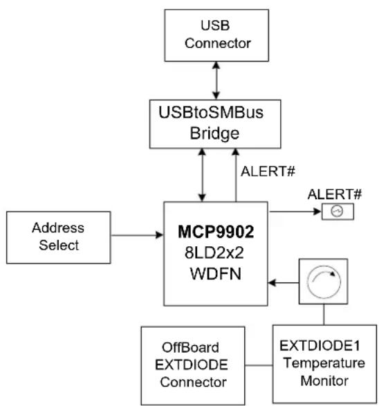
flowchart
graph TD
    A["USB Connector"] <--> B["USBtoSMBus Bridge"]
    B <--> C["MCP9902 8LD2x2 WDFN"]
    D["Address Select"] --> C
    E["OffBoard EXTDIOE Connector"] --> F["EXTDIODE1 Temperature Monitor"]
    G["ALERT#"] --> B
    H["ALERT#"] --> C
FIGURE 1-1: MCP9902 Temperature Sensor Evaluation Board Block Diagram.
The evaluation system is comprised of the MCP9902 Temperature Sensor Evaluation Board and the Microchip Chip Manager application. The MCP9902 Temperature Sensor Evaluation Board has the following features:
- Headers for connecting an external diode or CPU/GPU
- Resistance Error Correction verification using an on-board potentiometer
- USB-to-SMBus bridge for power and communications
The user can perform the following operations using the Chip Manager:
• Viewing and changing register values
- Saving settings of all registers, allowing for quick configuration at a later time
• Graphing of any register
The evaluation board was designed for ease of use and experimentation purposes.
Figure 1-2 shows the top silk screen of the MCP9902 Temperature Sensor Evaluation Board.
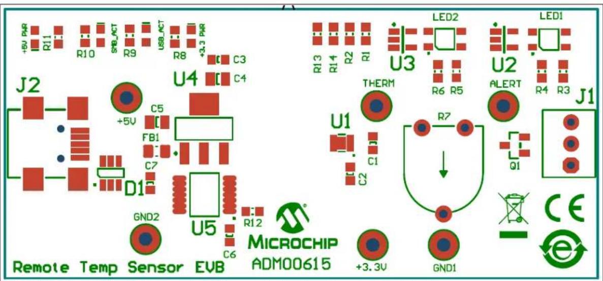
text_image
+5V PWR R11 R10 SWB_ACT R9 USB_ACT R8 +3.3 PWR C3 C4 U4 J2 +5V C5 FB1 C7 D1 GND2 U5 R12 MicroCHIP ADM00615 Remote Temp Sensor EVB +3.3V LED2 U3 LED1 THERM R6 R5 U2 ALERT R4 R3 J1 Q1 CE GND1FIGURE 1-2: MCP9902 Temperature Sensor Evaluation Board – Top Silk Screen.
1.4 WHAT DOES THE MCP9902 TEMPERATURE SENSOR EVALUATION BOARD KIT CONTAIN?
This MCP9902 Temperature Sensor Evaluation Board kit includes:
• MCP9902 Temperature Sensor Evaluation Board (ADM00615)
- USB to Micro-USB cable
- Important Information Sheet
Chapter 2. Installation and Operation
2.1 GETTING STARTED
2.1.1 System Requirements
To use the MCP9902 Temperature Sensor Evaluation Board, the following are required:
- A PC running the Microsoft® Windows® operating system
- A display resolution of 800x600 or larger, for viewing several windows simultaneously
• An available USB port
2.1.2 Installing the Evaluation Board
Follow the next steps to install the Microchip Chip Manager.
- Before installing and running Chip Manager, the MCP2221 driver and utility package needs to be installed on the local machine. If the driver and utility package have already been installed, this step may be skipped. The MCP2221 driver and utility package are located at: http://www.microchip.com/wwwproducts/Devices.aspx?product=MCP2221, under "Documentation & Software". Follow the on-screen instructions to complete the installation process.
- Download the Chip Manager from the board web page. Unzip the archive. The application's revision history and install/uninstall notes may be found in the readme.txt file.
- To install the Chip Manager application and the device driver on the PC, run ChipMan-windows-installer.exe file.
- Connect the supplied USB cable to an available USB port on the PC. Plug the mini-B end of the USB cable into the board connector J2. The +5V PWR, +3.3V PWR, and USB_ACT LEDs should illuminate.
- If the USB Bridge driver has not previously been installed on the selected USB port, the Driver Software Installation window pops up, prompting for the driver install (see Figure 2-1).

text_image
Driver Software Installation Installing device driver software USB Composite Device MCP2221 USB-I2C,UART Combo MCP2221 USB-I2C,UART Combo Ready to use Searching Windows Update... Searching Windows Update... Obtaining device driver software from Windows Update might take a while. Skip obtaining driver software from Windows Update Close Driver Software Installation Your device is ready to use USB Composite Device USB Serial Port (CCM10) USB Input Device Ready to use Ready to use Ready to use CloseFIGURE 2-1: Driver Software Installation Window.
- After the driver installation is complete, the initial setup screen for the Chip Manager application appears (see Figure 2-2). Click Next to start the installation.
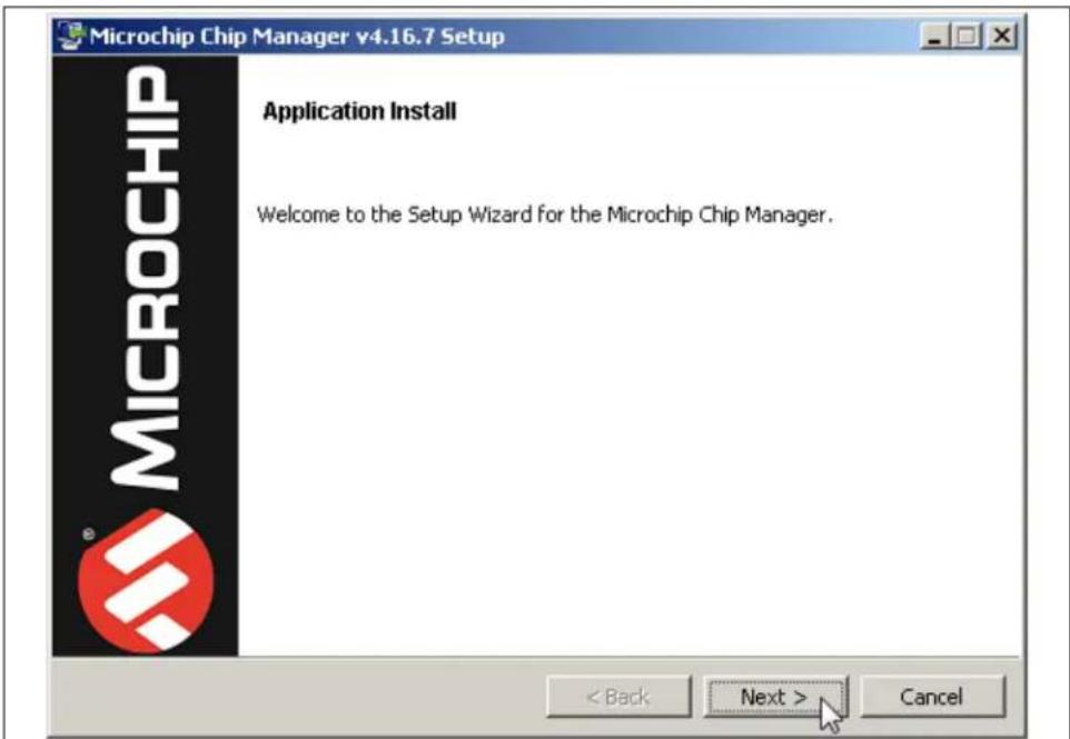
text_image
Microchip Chip Manager v4.16.7 Setup Application Install Welcome to the Setup Wizard for the Microchip Chip Manager. < Back Next > CancelFIGURE 2-2: Application Install Window.
- To proceed with the installation, read the License Agreement and accept by clicking the radio button corresponding to "I accept the agreement" then click Next.
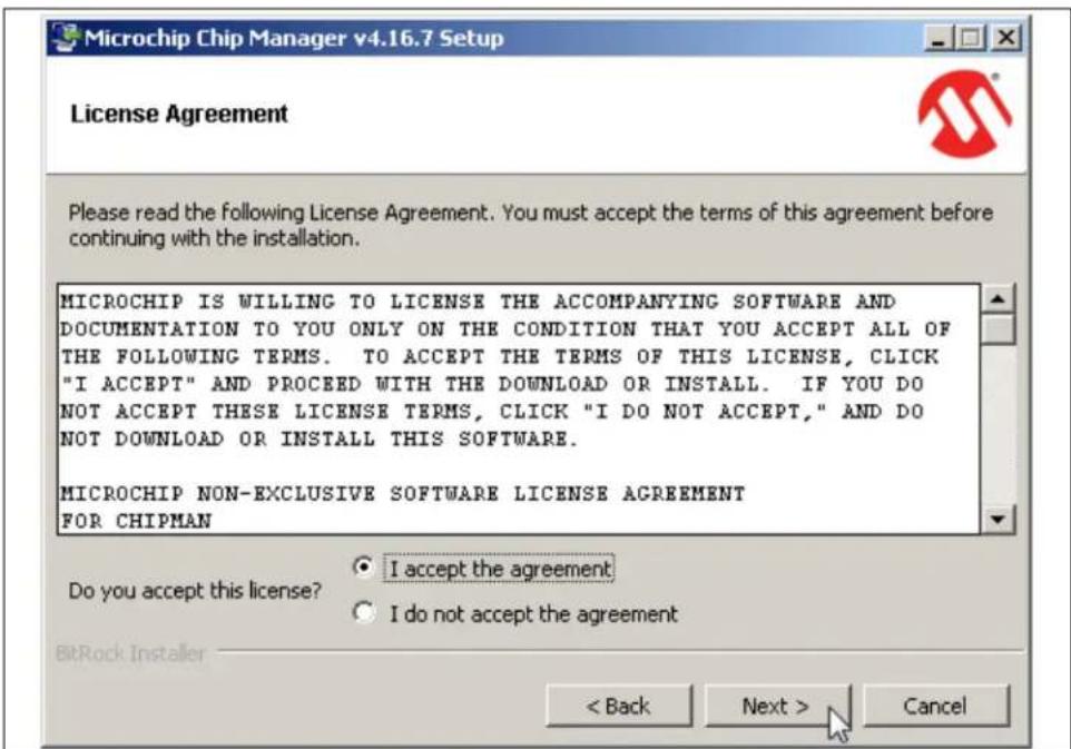
text_image
Microchip Chip Manager v4.16.7 Setup License Agreement Please read the following License Agreement. You must accept the terms of this agreement before continuing with the installation. MICROCHIP IS WILLING TO LICENSE THE ACCOMPANYING SOFTWARE AND DOCUMENTATION TO YOU ONLY ON THE CONDITION THAT YOU ACCEPT ALL OF THE FOLLOWING TERMS. TO ACCEPT THE TERMS OF THIS LICENSE, CLICK "I ACCEPT" AND PROCEED WITH THE DOWNLOAD OR INSTALL. IF YOU DO NOT ACCEPT THESE LICENSE TERMS, CLICK "I DO NOT ACCEPT," AND DO NOT DOWNLOAD OR INSTALL THIS SOFTWARE. MICROCHIP NON-EXCLUSIVE SOFTWARE LICENSE AGREEMENT FOR CHIPMAN Do you accept this license? • I accept the agreement • I do not accept the agreement < Back Next > CancelFIGURE 2-3: License Agreement Dialog.
- On the Installation Directory dialog, browse for the desired location or click Next to install in the default location (see Figure 2-4).
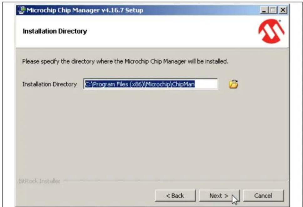
text_image
Microchip Chip Manager v4.16.7 Setup Installation Directory Please specify the directory where the Microchip Chip Manager will be installed. Installation Directory C:\Program Files (x86)\Microchip\ChipMan BitRock Installer < Back Next > CancelFIGURE 2-4: Installation Directory Dialog.
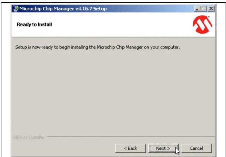
text_image
Microchip Chip Manager v4.16.7 Setup Ready to Install Setup is now ready to begin installing the Microchip Chip Manager on your computer. BitRock Installer < Back Next > CancelFIGURE 2-5: Ready to Install Dialog.
- The application setup window appears, showing the installation progress (see Figure 2-6).
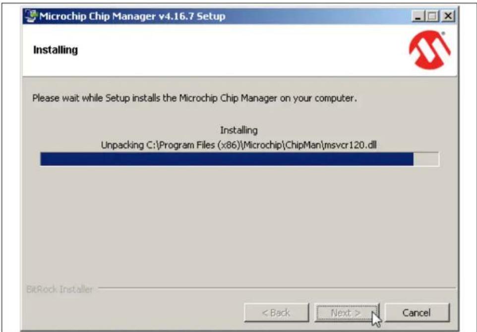
text_image
Microchip Chip Manager v4.16.7 Setup Installing Please wait while Setup installs the Microchip Chip Manager on your computer. Installing Unpacking C:\Program Files (x86)\Microchip\ChipMan\msvcr120.dll BitRock Installer < Back Next > CancelFIGURE 2-6: Setup Window – Installation Progress.
- After the setup is complete, the MSXML Parser used by the Chip Manager software is installed, as shown in Figure 2-7.

text_image
MSXML 6.0 Parser Setup Completing the MSXML 6.0 Parser Setup Setup has installed MSXML 6.0 Parser successfully. Click Finish to exit. < Back Finish CancelFIGURE 2-7: MSXML Parser Setup Window.
- Once the setup completes successfully, press Finish to exit the installer (see Figure 2-8).
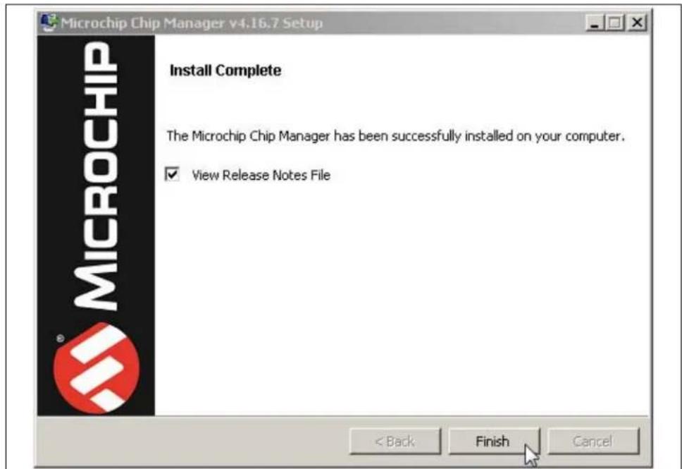
text_image
Microchip Chip Manager v4.16.7 Setup Install Complete The Microchip Chip Manager has been successfully installed on your computer. ✓ View Release Notes File < Back Finish CancelFIGURE 2-8: Install Complete Dialog.
- Start the software by either going to Windows Start button > All Programs > Microchip > Microchip Chip Manager or by clicking the software icon ( ) on the desktop. The evaluation board software will initialize while the Microchip Chip Manager with the Quick Help screen appears (see Figure 2-9).

text_image
Quick Help: The purpose of this utility is to allow the user to view and edit MCHP device registers in the Windows environment. To view a group of registers, select the appropriate group in the left pane. To edit the value of a register, double click the value in the "Last Value" column in the right upper pane. Type in the desired value. The register will be updated with the new value once the cursor leaves the edit window. Read only registers are denoted by "R" in the "R/W" column and editing of these register values is disallowed. Some registers have bit field definitions. They are displayed in the lower right pane. If the register is not read only (i.e. read/write) the value of each field can be edited by double clicking on the field value in the "Last Value" column of this pane. Type in the desired value to update the bit(s) of the register. The field may also be changed by making a selection from the field's drop down list. If a drop down list is available for this field, a combo box style button will appear at the right of the "Translation" column. Clicking the button will allow you to select a setting for the bit field from a drop down list. The current values of the registers can be saved to an external text file by using the Export feature. The saved text file can also be read back to the device by using the Import feature. Import only affects read/write registers.FIGURE 2-9: Microchip Chip Manager – Quick Help Window.
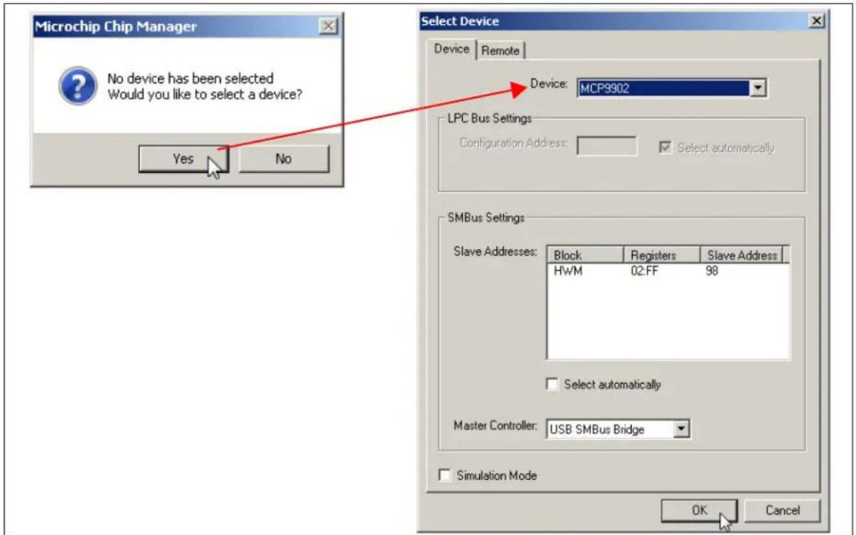
- If a message stating that no device has been selected appears, click Yes to select a device. Alternatively, go to the Chip Manager's main menu, select Options > Select Device. In either case, the Select Device window displays, as shown in Figure 2-10.
In the "Device" list of the "Select Device" window, choose "MCP9902". The "Master Controller" drop-down list should highlight "USB SMBus Bridge". Click OK to complete the device selection.
text_image
Microchip Chip Manager No device has been selected Would you like to select a device? Yes No Select Device Device Remote Device: MCP9902 LPC Bus Settings Configuration Address: Select automatically SMBus Settings Slave Addresses: Block Registers Slave Address HWM 02:FF 98 Select automatically Master Controller: USB SMBus Bridge Simulation Mode OK CancelFIGURE 2-10: Select Device Window.
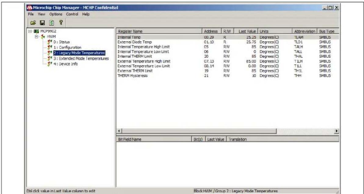
- From the Chip Manager main menu, ensure that Options > Auto Refresh Registers is checked. In the left panel, click the hardware monitor "HWM" to expand the content, then select any of the register groups, as shown in Figure 2-11. The SMB_ACT LED on the board starts blinking when any of the register groups are selected. The register values are automatically updated every second when the Auto Refresh option is on.
text_image
Microchip Chip Manager - MCHP Confidential File View Options Control Help MCP9902 HWM 0 : Status 1 : Configuration 2 : Legacy Mode Temperatures 3 : Extended Mode Temperatures 4 : Device Info Register Name Address R/W Last Value Units Abbreviation Bus Type Internal Temp 00.29 R 25.25 Degrees(C) TLAM SMBUS External Diode Temp 01.10 R 25.75 Degrees(C) TLD1 SMBUS Internal Temperature High Limit 05 RW 85 Degrees(C) TALH SMBUS Internal Temperature Low Limit 06 RW 0 Degrees(C) TALL SMBUS Internal THERM Limit 20 RW 85 Degrees(C) THAL SMBUS External Temperature High Limit 07.13 RW 85.00 Degrees(C) TLLH SMBUS External Temperature Low Limit 08.14 RW 0.00 Degrees(C) TILL SMBUS External THERM Limit 19 RW 85 Degrees(C) THIL SMBUS THERM Hysteresis 21 RW 10 Degrees(C) THH SMBUS Bit Field Name Bit(s) Last Value Translation Dbl click value in Last Value column to edit Block HWM / Group 2 : Legacy Mode TemperaturesFIGURE 2-11: Chip Manager – Register Groups.
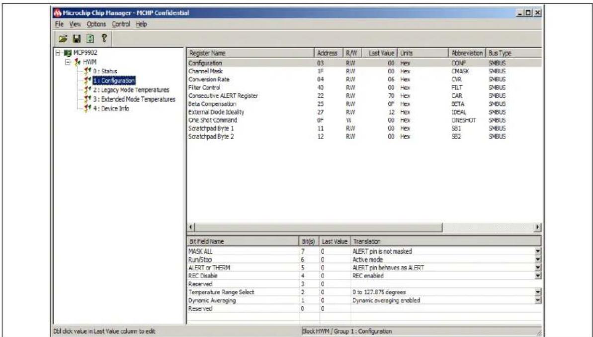
- To reveal the register descriptions in Chip Manager, highlight "Configuration" as shown in Figure 2-12. The "Bit Field Name" and "Translation" will be shown in the Chip Manager window. For a detailed description of each register, please refer to the MCP990X Data Sheet.
text_image
Microchip Chip Manager - MCHP Confidential File View Options Control Help MCP9902 HWM 0 : Status 1 : Configuration 2 : Legacy Mode Temperatures 3 : Extended Mode Temperatures 4 : Device Info Register Name Address R/W Last Value Units Abbreviation Bus Type Configuration 03 R/W 00 Hex CONF SMBUS Channel Mask 1F R/W 00 Hex CMASK SMBUS Conversion Rate 04 R/W 06 Hex CVR SMBUS Filter Control 40 R/W 00 Hex FILT SMBUS Consecutive ALERT Register 22 R/W 70 Hex CAR SMBUS Beta Compensation 25 R/W 0F Hex DCTA SMBUS External Diode Ideality 27 R/W 12 Hex IDEAL SMBUS One Shot Command 0F W 00 Hex ONESHOT SMBUS Scratchpad Byte 1 11 R/W 00 Hex SB1 SMBUS Scratchpad Byte 2 12 R/W 00 Hex SB2 SMBUS Bit Field Name Bt(s) Last Value Translation MASK ALL 7 0 ALERT pin is not masked Run/Stop 6 0 Active mode ALERT or THERM 5 0 ALERT pin behaves as ALERT REC Disable 4 0 REC enabled Reserved 3 0 Temperature Range Select 2 0 0 to 127.875 degrees Dynamic Averaging 1 0 Dynamic averaging enabled Reserved 0 0 Dbl click value in Last Value column to edit Block HWM / Group 1 : ConfigurationFIGURE 2-12: Chip Manager – Configuration Window.
MCP9902 Temperature Sensor Evaluation Board User's Guide
NOTES:
Chapter 3. Hardware Description
3.1 INTRODUCTION
The MCP9902 Temperature Sensor Evaluation Board (EVB) provides the means to demonstrate all features of the MCP9902 device, and allows the registers to be viewed and modified. LEDs indicating status information and test points are included to enable system voltage monitoring using a voltmeter or an oscilloscope.
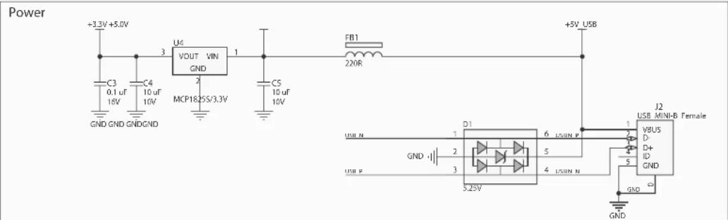
3.1.1 Power Source
The MCP9902 EVB requires only one universal serial bus (USB) connection for power. An on-board LDO regulates the +5V USB power to +3.3V required by the MCP9902 and other evaluation board circuitry.
3.2 USB-TO-I ^2 C/SMBUS BRIDGE
The MCP9902 EVB implements Microchip's MCP2221 protocol converter to ensure communication from USB to I²C. Power is delivered to the bridge from the on-board LDO.
3.3 RESISTANCE ERROR CORRECTION (REC)
The MCP9902 has a series resistance adjustment on the DN line. To demonstrate the Resistance Error Correction (REC) feature, potentiometer R7 can be tuned to vary the resistance. When REC is enabled, the temperature will not change as the resistance is increased. When REC is disabled, a significant temperature error will occur; every ohm of resistance increases the temperature error by approximately 0.6^/ .
3.4 TEST POINTS
The MCP9902 Temperature Sensor Evaluation Board includes test points for the following signals:
• A L E Output
• THE Rulput
• +5V USB supply
• +3.3V analog supply
• GND
3.5 LED INDICATORS
Table3-1 details the status of the LEDs for the following signals:
TABLE 3-1: LED STATUS INDICATORS
| Signal When LED is OFF When LED is ON | ||
| is not active - GREEN | is active - RED | |
| is not active - GREEN THERM is active - | ||
| +3.3V PWR +3 | 3V analog voltage is not available +3.3V | analog voltage is available - GREEN |
| +5V PWR | USB +5V is not available | USB +5V is available - GREEN |
| USB_ACT | No Activity on USB port | Activity on USB port - GREEN |
| SMB_ACT | No Activity on SMBus | Activity on SMBus - GREEN |
3.6 REMOTE DIODES
The MCP9902 EVB is populated with an on-board transistor (Q1) with the base terminal shorted to the collector terminal. This type of connection is known as a diode-connected transistor. A latched header (J1) allows for an off-board connection to a remote diode, a remote CPU or GPU attached with a cable assembly (see Table 3-2).
To connect to an off-board CPU, GPU or cable assembly, remove the on-board transistor, Q1, and refer to Table 3-2 for the proper connections. Ensure a common ground exists between the off-board diode (GPU, etc.) and the evaluation board by connecting to the ground of the EVB via pin 2 of J1. The off-board diode of a CPU or GPU requires proper biasing, so it is recommended to consult the CPU manufacturer's data sheet for guidance on interfacing to the thermal diode.
Please refer to the MCP9902 Temperature Sensor Evaluation Board schematic in Appendix A. "Schematic and Layouts" for details on the evaluation board header connections.
TABLE 3-2: REMOTE DIODE CONFIGURATIONS
| Header | Configuration | Pin 1 | Pin 2 | Pin 3 |
| J1 | On-board diode (Q1) | Collector/Base Shorted | N/A | Emitter |
| Diode with Shielded Cable Assembly | Collector/Base Shorted | Shield Ground | Emitter | |
| Diode without Shielded Cable Assembly | Collector/Base Shorted | N/A | Emitter | |
| CPU/GPU Diode | Emitter | Ground | Base |
3.7 OTHER SENSOR FEATURES
Other features, such as conversion rate, dynamic averaging and digital filtering, can be controlled with the MCP9902 registers. For details on the register description, refer to the MCP990X Data Sheet.
Chapter 4. Software Description
4.1 CHIP MANAGER APPLICATION OVERVIEW
Chip Manager is a Microchip Technology Inc. application that enables the user to display temperature readings, set temperature limits and read/write configuration register values. Chip Manager initially displays a Quick Help screen. For detailed information on application features and usage, select Help > Contents to display the HTML-based Help document.
4.1.1 Real-Time Register Graphs
The Chip Manager software has the ability to plot register values in real-time, up to a continuous rate of 4 Hz.
4.1.2 Selecting Registers to Plot
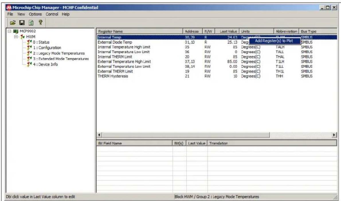
- To plot a register, right-click the desired register name or value. Select Add Register(s) to Plot from the context menu (see Figure 4-1), to add the register or value to the plot list.
text_image
Microchip Chip Manager - MCHP Confidential File View Options Control Help MCP9902 HWM 0 : Status 1 : Configuration 2 : Legacy Mode Temperatures 3 : Extended Mode Temperatures 4 : Device Info Register Name Address R/W Last Value Units Abbreviation Bus Type Internal Temp 00, 29 R 24.63 Degree(C) R-M SMBUS External Diode Temp 01, 10 R 25.13 Degree Add Register(s) to Plot SMBUS Internal Temperature High Limit 05 RW 85 Degrees(C) TALH SMBUS Internal Temperature Low Limit 06 RW 0 Degrees(C) TALL SMBUS Internal THERM Limit 20 RW 85 Degrees(C) THAL SMBUS External Temperature High Limit 07, 13 RW 85.00 Degrees(C) TILL SMBUS External Temperature Low Limit 08, 14 RW 0.00 Degrees(C) TILL SMBUS External THERM Limit 19 RW 85 Degrees(C) THIL SMBUS THERM Hysteresis 21 RW 30 Degrees(C) THH SMBUS Bit Field Name Bit(c) Last Value Translation Dbl click value in Last Value column to edit Block HWM / Group 2 : Legacy Mode TemperaturesFIGURE 4-1: Adding Registers to Plot.
- Once the desired register is added to plot, a graphic plot window will appear with a legend on top, as shown in Figure 4-2. The two windows can be rearranged independently.
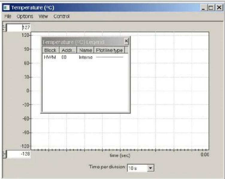
text_image
Temperature (°C) Legend Block Add... Name Plot line type HWM 00 Interna Time per division 10 sFIGURE 4-2: Register Plot - Temperature Window.
- To plot additional registers, go back to the Chip Manager main window and repeat Step 1.
4.1.3 Starting the Plots
Before starting the plots, it is important to disable the auto refreshing of the registers. On the Chip Manager main menu, ensure that Options > Auto Refresh Registers is not checked. All plots can be started simultaneously by selecting Control > Plots > Start All Plots from the menu in the main application window. Multiple plots will be in sync if they are started simultaneously.
Individual plots may be paused at any time by clicking Control > Pause in the plot window. This will not cause loss of captured data on the other plot windows.
For a better view of the plot, select a different "Time per division" value in the drop-down menu at the bottom of the plotting window. This scale change affects both the Real-time mode and the Playback mode, while the rate at which data is recorded remains unaffected.
4.1.4 Sampling a Plot
Figure 4-3 is an example of temperature history. Internal Temperature, External Diode 1 Temperature and External Diode 1 High Limit are selected for plotting. The results after starting the plot are that the External Diode Temperature High Limit is reduced, the External Diode 1 starts at room temperature and is then heated by simply placing a finger on the external diode Q1.

line
| Time (sec) | Value | | ---------- | ----- | | 00.29 | 26.0 | | 01.10 | 26.0 | | 07.13 | 26.0 |FIGURE 4-3: MCP9902 Temperature History Graph.
4.1.5 Exporting and Importing the Plot Data
The data on each plot window may be stored in a semicolon-separated text file. To save the data, follow the steps:
-
Stop the plotting by selecting Control > Stop from the plot window, or Control > Plots > Stop All Plots from the Chip Manager main window.
-
Select File > Export from the plot window to save the data.
To review saved data, select File > Import from an open plot window and then select the file name to open.
Note: Importing a saved data file into a plot window with a different data type is not allowed by the Chip Manager application. In this case, a warning message will display. It is recommended to choose a file name that best describes the data type when exporting the plot data.
MCP9902 Temperature Sensor Evaluation Board User's Guide
NOTES:
Appendix A. Schematic and Layouts
A.1 INTRODUCTION
This appendix contains the following schematics and layouts for the MCP9902
Temperature Sensor Evaluation Board:
- Board – MCP9902 and Interface Schematic
- Board – USB-to-SMBus Bridge Schematic
- Board – Top Silk
- Board – Top Copper and Silk
- Board – Top Copper
- Board – Bottom Copper
- Board – Bottom Copper and Silk
- Board – Bottom Silk
A.2 BOARD - MCP9902 AND INTERFACE SCHEMATIC
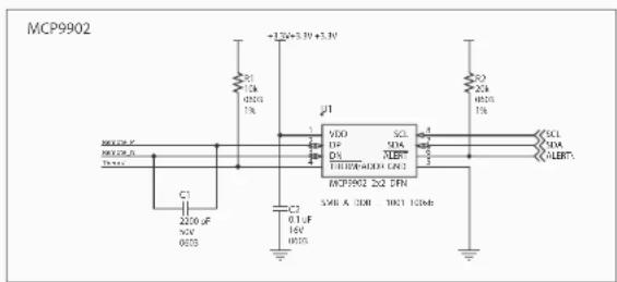
text_image
MCP9902 +1.3V + 3.3V + 3.3V C1 12A 0501 1k J1 VDD SCL 1V X1A LFP T1R0/4400 LCN2 C2 0.1UF 14V 0505 C3 2200 uF 50V 0105 MCP9902 2x2 DFN SMB A 30Ω 10Ω 10Ω SCL 1kA 1kB CLK CLK CLK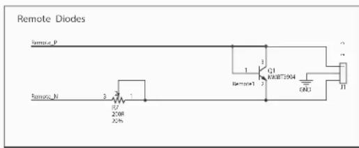
text_image
Remote Diodes Remote P Remote N 3 20 20R 2.5h 1 3 Q1 RETM1 Q1M1904 END J1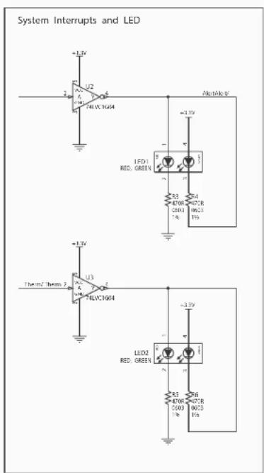
text_image
System Interrupts and LED +1.3V U2 A 400V XG94 NonMnK LED1 RED, GREEN R3 4768 00'0" 2501 1µ 19623 1µ +1.3V Therm2 Therm 2 U3 A 400V XG94 LED2 RED, GREEN +1.3V R3 4768 00'0" 2501 1µ 19623 1µ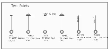
text_image
Test Points 45V TP LOOP Change +V-24 GND1 TP LOOP Black GND 43.3V TP LOOP Red L55V GND2 TP LOOP Black GND T-L55V IP LOOP White T-L55A ACR1 IP LOOP White ACR2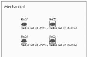
text_image
Mechanical PAD1 PAD2 PAD3 PAD4 PAD4 Fuel Cyl 07.0453 PAD4 Fuel Cyl 07.0453 PAD4 Fuel Cyl 07.0453A.3 BOARD - USB-TO-SMBUS BRIDGE SCHEMATIC
text_image
Power +3.3V +5.0V C3 0.1 uF C4 10 uF MCP18/25V/3.3V 1 GND GND GNDGND U6 VOUT VIN GND 2 CS 10 uF 10V FB1 220R +5V USB J2 USB MINI-B Female V8US D+ D+ ID GND USB N 1 6 USIN P GND -1 2 5 USB P 3 4 USIN N 5.25V GND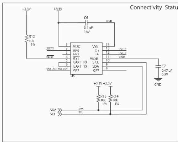
text_image
Connectivity Status +3.3V +3.3V C6 0.1 uF 16V GND R12 10k 1% R13 10k 1% SDA SCL 3.3V +3.3V 3.3V 4 5 6 7 8 9 10 11 12 13 14 VDC VSS GP0 GP1 GP2 VDD UAR1 RX SCL UAR1 TX SDA US USL ACT UAR ACC GP3 GND C7 0.47 uF 6.3V
text_image
+3.3V +3.3V R8 1k 1% +3.3 PWR GREEN GND R9 1k 1% USB ACT USB ACT GREEN +3.3V R10 1k 1% SMB ACT GREEN 2M ACT +5V USB R11 2.2k 1% +5V PWR GREEN GNDA.4 BOARD - TOP SILK

text_image
+5V PAR R11 R10 SHB_ACT R9 USB_ACT R8 +3.3 PAR C3 C4 U4 J2 +5V FB1 C7 D1 GND2 U5 C6 Remote Temp Sensor EVB MicroCHIP ADM00615 LED2 R13 R14 R2 R1 THERM U1 C1 C2 LED1 U3 R6 R5 U2 ALERT Q1 GND1 +3.3V CE eA.5 BOARD - TOP COPPER AND SILK

text_image
J2 U1 U2 U3 U4 U5 MicroCHIP AOM00615 Remote Temp Sensor EVB +3.3V +2.8V +2.5V +2.3V +2.1V +1.9V +1.7V +1.5V +1.3V +1.1V +0.9V +0.7V +0.5V +0.3V +0.1V -0.1V -0.3V -0.5V -0.7V -0.9V -1.1V -1.3V -1.5V -1.7V -1.9V -2.1V -2.3V -2.5V -2.7V -2.9V -3.1V -3.3V -3.5V -3.7V -3.9V -4.1V -4.3V -4.5V -4.7V -4.9V -5.1V -5.3V -5.5V -5.7V -5.9V -6.1V -6.3V -6.5V -6.7V -6.9V -7.1V -7.3V -7.5V -7.7V -7.9V -8.1VA.6 BOARD - TOP COPPER

natural_image
Red printed circuit board with white traces and circular components (no text or symbols)A.7 BOARD - BOTTOM COPPER
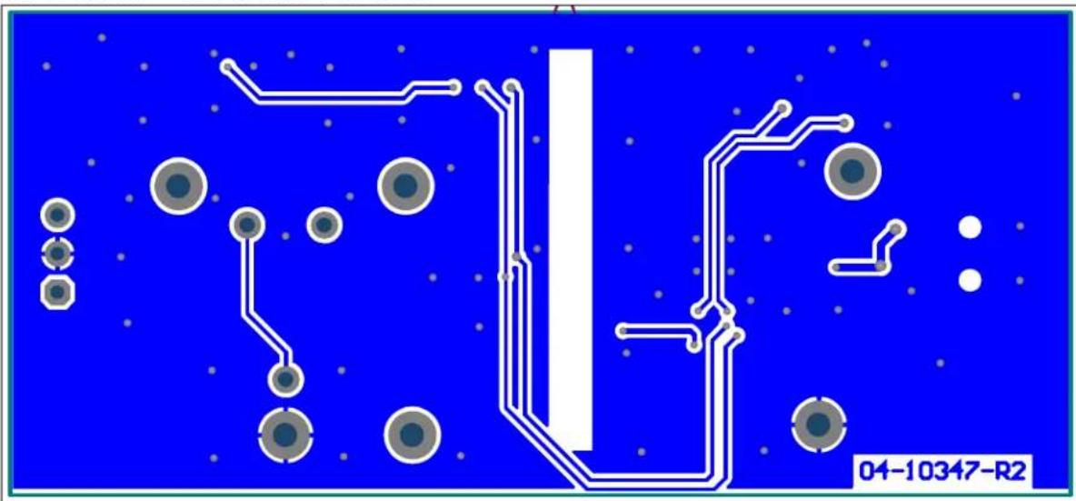
natural_image
Pure electrical circuit lines without any symbols or text, rendered on a blue background with no readable text or labels.A.8 BOARD – BOTTOM COPPER AND SILK

text_image
PAD3 PAD1 PAD4 04-103A7-R2A.9 BOARD - BOTTOM SILK

text_image
PAD3 PAD1 PAD4 PAD2Appendix B. Bill of Materials (BOM)
TABLE B-1: BILL OF MATERIALS (BOM)
| Qty. | Reference Description | tion Manufacturer Part Number | ||
| 4 +3 | 3 PWR, +5V PWR, SMB_ACT, USB_ACT | Diode LED green 2.2V 25 mA 15 mcd Clear SMD 0603 | Kingbright Corp. APT1608 | SGC |
| 1 +3 | 3V Conn. TP Loop | Red TH Keystone Electronics | Corp. | 5010 |
| 1 +5 | V Conn. TP Loop | Orange TH Keystone Electronics Corp. | Corp. | 5013 |
| 2 ALERT, THERM | Conn. TP Loop White TH | Keystone Electronics Corp. | Corp. | 5012 |
| 1 C1 | Cap. ceramic 2200 pF 50V 10% X7R SMD 0603 | KEMET® | C0603C222K5RACTU | |
| 3 C2, C3, C6 | Cap. ceramic 0.1 μF 16V 10% X7R SMD 0603 | NIC Components Corp. | NMC0603X7R104K16TRPF | |
| 2 C4, C5 | Cap. ceramic 10 μF 10V 10% X5R SMD 0805 | Taiyo Yuden Co., Ltd. | LMK212BJ106KD-T | |
| 1 C7 | Cap. ceramic 0.47 μF 6.3V 10% X5R SMD 0603 | Murata Electronics® | GRM188R60J474KA01D | |
| 1 D1 | Diode TVSARR USBLC6-2SC6 5.25V SMD SOT-23-6 | STMicroelectronics | USBLC6-2SC6 | |
| 1 FB1 | Ferrite 2A 220R | SMD 0805 Murata Electronics | BLM21PG221SN1D | |
| 2 GND1, GND2 | Conn. TP Loop Black TH | Keystone Electronics Corp. | Corp. | 5011 |
| 1 J1 | Conn. header-2.54 male 1x3 Tin Lock 7.49 MH TH vert. | TE Connectivity, Ltd. | 640456-3 | |
| 1 J2 | Conn. USB MINI-B female SMD R/A | Hirose Electric Co., Ltd. | UX60-MB-5ST | |
| 2 LED1, LED2 | Diode LED bi red, green 2V, 2.2V, 30 mA, 25 mA 4-SMD | Lumex® Inc. | SSL-LXA3025IGC-TR | |
| 4 PAD1, PAD2, PAD3, PAD4 | Mech. HW rubber pad cylindrical D7.9 H5.3 black | 3M | SJ61A11 | |
| 1 PCB | MCP9902 Temperature Sensor Evaluation Board - Printed Circuit Board | Microchip Technology Inc. | 104-10347 | |
| 1 Q1 | Trans. BJT NPN MMBT3904 40V 200 mA 310 mW SOT-23-3 | Diodes® Incorporated | MMBT3904-7 | |
| 1 | R1 | Res. TKF 10 kΩ 1% 1/10W SMD 0603 | NIC Components Corp. | NRC06F1002TRF |
| 1 | R2 | Res. TKF 20 kΩ 1% 1/10W SMD 0603 | Yageo Corporation | 9C06031A2002FKHFT |
| Qty. | Reference | Description | Manufacturer | Part Number |
| 4 R3 | R4, R5, R6 Res. | TKF 470R 1% 1/10W SMD 0603 | Yageo Corporation RC0603FR-07470RL | |
| 1 R7 | Res. Trimmer Cermet | 200R 20%500 mW TH 3352E | Bourns® Inc. 3352E-1-201LF | |
| 3 R8 | R9, R10 Res. TKF | 1 kΩ 1% 1/10W SMD 0603 | Panasonic® – ECG ERJ-3EKF1001V | |
| 1 | R 1 1 | R e s . T K F 0603 | Panasonic – ECG ERJ-3EKF22010W SMD | |
| 3 R1 | 2, R13, R14 Res. | TF 10 kΩ 1% 1/8W SMD 0603 | Vishay Intertechnology, Inc. | MCT06030C1002FP500 |
| 1 U1 | MCP9902 WDFN-8 | Microchip Technology Inc. | MCP9902-E/RW | |
| 2 | U2, U3 | IC LOGIC 74LVC1G04 SOT-23-5 | Texas Instruments | SN74LVC1G04DBVR |
| 1 U4 | MCHP ANALOG LDO 3.3VMCP1825ST-3302E/DB SOT-223-3 | Microchip Technology Inc. | MCP1825S-3302E/DB | |
| 1 U5 | USB-to-I | ^2C^TM/UART SMBus Protocol Converter with GPIO | Microchip Technology Inc. | MCP2221-I/ST |
Note: The components listed in this Bill of Materials are representative of the PCB assembly. The released BOM used in manufacturing uses all RoHS-compliant components.
NOTES:
Worldwide Sales and Service
AMERICAS
Corporate Office
2355 West Chandler Blvd.
Chandler, AZ 85224-6199
Tel: 480-792-7200
Fax: 480-792-7277
Technical Support:
http://www.microchip.com/
support
Web Address:
www.microchip.com
Atlanta
Duluth, GA
Tel: 678-957-9614
Fax: 678-957-1455
Austin, TX
Tel: 512-257-3370
Boston
Westborough, MA
Tel: 774-760-0087
Fax: 774-760-0088
Chicago
Itasca, IL
Tel: 630-285-0071
Fax: 630-285-0075
Cleveland
Independence, OH
Tel: 216-447-0464
Fax: 216-447-0643
Dallas
Addison, TX
Tel: 972-818-7423
Fax: 972-818-2924
Detroit
Novi, M
Tel: 248-848-4000
Houston, TX
Tel: 281-894-5983
Indianapolis
Noblesville, IN
Tel: 317-773-8323
Fax: 317-773-5453
Los Angeles
Mission Viejo, CA
Tel: 949-462-9523
Fax: 949-462-9608
New York, NY
Tel: 631-435-6000
San Jose, CA
Tel: 408-735-9110
Canada - Toronto
Tel: 905-673-0699
Fax: 905-673-6509
ASIA/PACIFIC
Asia Pacific Office
Suites 3707-14, 37th Floor
Tower 6, The Gateway
Harbour City, Kowloon
Hong Kong
Tel: 852-2943-5100
Fax: 852-2401-3431
Australia - Sydney
Tel: 61-2-9868-6733
Fax: 61-2-9868-6755
China - Beijing
Tel: 86-10-8569-7000
Fax: 86-10-8528-2104
China - Chengdu
Tel: 86-28-8665-5511
Fax: 86-28-8665-7889
China - Chongqing
Tel: 86-23-8980-9588
Fax: 86-23-8980-9500
China - Dongguan
Tel: 86-769-8702-9880
China - Hangzhou
Tel: 86-571-8792-8115
Fax: 86-571-8792-8116
China - Hong Kong SAR
Tel: 852-2943-5100
Fax: 852-2401-3431
China - Nanjing
Tel: 86-25-8473-2460
Fax: 86-25-8473-2470
China - Qingdao
Tel: 86-532-8502-7355
Fax: 86-532-8502-7205
China - Shanghai
Tel: 86-21-5407-5533
Fax: 86-21-5407-5066
China - Shenyang
Tel: 86-24-2334-2829
Fax: 86-24-2334-2393
China - Shenzhen
Tel: 86-755-8864-2200
Fax: 86-755-8203-1760
China - Wuhan
Tel: 86-27-5980-5300
Fax: 86-27-5980-5118
China - Xian
Tel: 86-29-8833-7252
Fax: 86-29-8833-7256
ASIA/PACIFIC
China - Xiamen
Tel: 86-592-2388138
Fax: 86-592-2388130
China - Zhuhai
Tel: 86-756-3210040
Fax: 86-756-3210049
India - Bangalore
Tel: 91-80-3090-4444
Fax: 91-80-3090-4123
India - New Delhi
Tel: 91-11-4160-8631
Fax: 91-11-4160-8632
India - Pune
Tel: 91-20-3019-1500
Japan - Osaka
Tel: 81-6-6152-7160
Fax: 81-6-6152-9310
Japan - Tokyo
Tel: 81-3-6880-3770
Fax: 81-3-6880-3771
Korea - Daegu
Tel: 82-53-744-4301
Fax: 82-53-744-4302
Korea - Seoul
Tel: 82-2-554-7200
Fax: 82-2-558-5932 or
82-2-558-5934
Malaysia - Kuala Lumpur
Tel: 60-3-6201-9857
Fax: 60-3-6201-9859
Malaysia - Penang
Tel: 60-4-227-8870
Fax: 60-4-227-4068
Philippines - Manila
Tel: 63-2-634-9065
Fax: 63-2-634-9069
Singapore
Tel: 65-6334-8870
Fax: 65-6334-8850
Taiwan - Hsin Chu
Tel: 886-3-5778-366
Fax: 886-3-5770-955
Taiwan - Kaohsiung
Tel: 886-7-213-7828
Taiwan - Taipei
Tel: 886-2-2508-8600
Fax: 886-2-2508-0102
Thailand - Bangkok
Tel: 66-2-694-1351
Fax: 66-2-694-1350
EUROPE
Austria - Wels
Tel: 43-7242-2244-39
Fax: 43-7242-2244-393
Denmark - Copenhagen
Tel: 45-4450-2828
Fax: 45-4485-2829
France - Paris
Tel: 33-1-69-53-63-20
Fax: 33-1-69-30-90-79
Germany - Dusseldorf
Tel: 49-2129-3766400
Germany - Karlsruhe
Tel: 49-721-625370
Germany - Munich
Tel: 49-89-627-144-0
Fax: 49-89-627-144-44
Italy - Milan
Tel: 39-0331-742611
Fax: 39-0331-466781
Italy - Venice
Tel: 39-049-7625286
Netherlands - Drunen
Tel: 31-416-690399
Fax: 31-416-690340
Poland - Warsaw
Tel: 48-22-3325737
Spain - Madrid
Tel: 34-91-708-08-90
Fax: 34-91-708-08-91
Sweden - Stockholm
Tel: 46-8-5090-4654
UK - Wokingham
Tel: 44-118-921-5800
Fax: 44-118-921-5820
07/14/15