CEC1702 - Microcontroller Microchip - Free user manual and instructions
Find the device manual for free CEC1702 Microchip in PDF.

User questions about CEC1702 Microchip
0 question about this device. Answer the ones you know or ask your own.
Ask a new question about this device
Download the instructions for your Microcontroller in PDF format for free! Find your manual CEC1702 - Microchip and take your electronic device back in hand. On this page are published all the documents necessary for the use of your device. CEC1702 by Microchip.
USER MANUAL CEC1702 Microchip
PCB Layout Guide for CEC1702
Author: Tom Tse
Microchip Technology Inc.
INTRODUCTION
This application note provides information on design considerations for a printed circuit board (PCB) for the Microchip CEC1702 device.
The design of the PCB requires care to provide good supply and ground paths; in addition, other design issues are addressed in this document.
The functional blocks in the CEC1702 have different requirements for routing and external connections, which are also outlined in this application note.
Please see References for device-level information such as V_CC1 power planes, and mechanical package information for the 84-Pin WFBGA.
This document includes the following topics:
• Section 1.0, "General Layout Considerations," on page 2
• Section 2.0, "Miscellaneous Considerations," on page 9
• Section 3.0, "JTAG Design and Layout Guide," on page 19
Audience
This document is written for a reader that is familiar with hardware design. The goal of this application note is to provide information about sensitive areas of the CEC1702 PCB layout.
References
The following documents should be referenced when using this application note. Please contact your Microchip representative for availability.
• Microchip CEC1702 Data Sheet
- Microchip CEC1702 EVB Reference Schematic
- I²C-bus specification and user manual, Rev. 6 - 4 April, 2014 or later (see www.nxp.com/documents/user_manual/UM10204.pdf)
Package Information
The CEC1702 device is currently available in the following package:
• CEC1702 for 84-pin, WFBGA
1.0 GENERAL LAYOUT CONSIDERATIONS
This section describes layout considerations for the CEC1702 device. This includes the following topics:
• Section 1.1, "Decoupling Capacitors," on page 2
• Section 1.2, "32.768kHz Crystal Oscillator," on page 4
• Section 1.3, "CAP Pins, AVSS/GND Connection," on page 5
• Section 1.4, "PCB Mounted Analog Power Supply Filter for PLL Usage," on page 5
• Section 1.5, "BGA Package PCB Layout Considerations," on page 6
1.1 Decoupling Capacitors
This section includes the following topics:
• Section 1.1.1, "CEC1702 WFBGA Capacitors," on page 2
Decoupling capacitors should be placed as close to the chip as possible to keep series inductance low. When the capacitors are mounted on the bottom side of the PCB, the capacitors are connected to the ground plane from the bottom layer directly using the shortest path to the device. Each VCC pin should have a 0.1 F capacitor located as close to the pin as possible. Bypass capacitors should be placed close to the supply pins of the CEC1702 with short and wide traces.
The CEC1702 has an integrated voltage regulator to supply the core circuitry. Decoupling this regulator requires a critical capacitor of 1 F on the CAP pin. ESR of this 1 F capacitor, including the routing resistance, must be less than 100 mOhm.
Capacitors may carry large currents that generate magnetic fields, inducing noise on nearby traces. Sensitive traces such as the 32kHz crystal should be separated by at least five times the trace width from decoupling capacitors when possible.
Connecting decoupling caps to power and ground planes using two vias per pad will reduce series inductance.
• FIGURE 1-1: on page 3 shows decoupling for the CEC1702 84-pin WFBGA.
The VCC pin decoupling capacitors can use any typical 16V 10% Ceramic. See also the CEC1702 EVB Schematics and Bill of Materials.
1.1.1 CEC1702 WFBGA CAPACITORS
• Figure 1-1 shows decoupling for the CEC1702 84-pin WFBGA package.
Note: The capacitors can use any typical 16V 10% ceramic.
FIGURE 1-1: CEC1702 DECOUPLING IN 84-PIN WFBGA PACKAGE
text_image
Y1 C5 C6 A B C20 2 Vias to VTR C9 D E C13 C14 2 Vias to GND G H J K 1uF Low ESR C7 C10 C11CEC1702 WFBGA (Bottom View)
Note: (For Part Numbers see CEC1702 DC Assy 6808 Schematic)
C9 = 0.1uF on VBAT
C10 = 0.1uF on VTR1
C11 = 0.1uF on VTR2
C14 = 0.1uF on VTR_REG
C13 = 0.1uF & C20 = 22uF between VTR_PLL & VSS_PLL
C7 = 1uF Low ESR +/-20% <100 mOhm on VR_CAP (X5R or X7R)
Y1 = 9pF load crystal, with C5, C6 = 10pF decoupling
1.2 32.768kHz Crystal Oscillator
This section describes specific layout and design considerations for the 32.768kHz crystal oscillator; this can be used to source the internal 32kHz clock domain, in lieu of the silicon oscillator or an external pin. The crystal implementation is required to support the RTC function within the CEC1702.
1.2.1 32.768KHZ CRYSTAL OSCILLATOR LAYOUT
The CEC1702 32kHz crystal oscillator is designed to generate an synchronous on-chip clock signal with an appropriate external oscillator crystal. The design has been optimized for low power (1.5 W typical), stability and minimum jitter using a general purpose parallel resonant 32kHz crystal. For a suggested part number, please see the CEC1702 EVB schematic (see References).
This unique low power crystal oscillator drive circuit means that a standard inverter crystal layout should not be used. The design has been characterized to allow a variation of 4pF to 18pF on each pin. Based on the following load capacitance calculation, Microchip recommends 10pf load capacitors with a crystal that has a 9pf CI rating. Other than these capacitors, no additional external components are required for normal operation of the clock circuit.
$$ E f f e c t i v e L o a d C a p a c i t a n c e = C 1 = \frac {[ C 1 1 + C p i n _ {x} t a l 2 ] [ C 1 2 + C p i n _ {x} t a l 1 ]}{C 1 1 + C p i n _ {x} t a l 2 + C 1 2 + C p i n _ {x} t a l 1} + C b r d $$
Where:
• C12 is the cap from pin XTAL1 to ground.
• C13 is the cap from pin XTAL2 to ground.
- Cpin_xtal2 is the pin capacitance of pin XTAL2. This is estimated to be 5pf (Note 1-1).
- Cpin_xtal1 is the pin capacitance of pin XTAL1. This is estimated to be 3pf (Note 1-1).
• Cbrd is estimated at 1.5pF.
Note 1-1 At the time of publication, the CEC1702 silicon has not been characterized. Please check with your Microchip FAE for final pin capacitance values after silicon validation is complete. Any variation from the estimates provided here could change the crystal Cl value requirement.
1.2.2 CRYSTAL ACCURACY
The accuracy of the 32kHz input translates directly into accuracy of the internal clock and the functions in the CEC1702 using the 32kHz: 32KHZ_OUT, week timer, hibernation timers, and so forth.
The accuracy, with regard to actual error in time can be illustrated as such: +/-1ppm of error in frequency corresponds to 32.768 kHz x 1ppm x 10^-6 = +/-0.032768 Hz. This translates into \~1 sec/sec or \~+/-0.086 sec/day.
Based on customer RTC accuracy timer requirements, Microchip recommends using a +/-20ppm crystal. This would equal approximately +/-2 sec/day, other factors discounted.
For arguments sake, it is safe to say that stray capacitance is difficult to calculate exactly. So, as an exercise in completeness, this calculation describes the effect of each picofarad of additional capacitance over/under the crystal C_load value:
$$ p p m / p F = \frac {C _ {1} x 1 0 ^ {6}}{2 (C _ {O} + C _ {L}) ^ {2}} $$
where C_0 is the shunt capacitance, C_1 is the motional capacitance and C_L is the load capacitance of the chosen crystal (these numbers can be found in the crystal data sheet). For example, using a crystal with C_0 = 0.8pF , C_1 = 0.0019pF , C_L = 12.5pF , we get a shift of 5.37ppm/pF. So, in terms of time, each pF of added/subtracted capacitance is approximately 5.37 × 0.086 = +/-462 msec/day for this particular crystal.
This example is meant to illustrate the magnitude of the potential error. In practice, slight capacitance mismatch does not equate to many seconds a day.
1.2.3 SINGLE ENDED CLOCKING
An external clock source (maximum voltage of 3.3V) may be applied to the XTAL2 pin if the XOSEL bit in Clock Enable Register configures as a single-ended 32.768 kHz clock input (SUSCLK). The XTAL1 pin should be left floating. If an external clock source is used, the designer must ensure that the source is available in all desired power states in which the EC will be active.
1.3 CAP Pins, AVSS/GND Connection
The recommended filtering for the CAP pin on the CEC1702 is shown in Figure 1-2, for WFBGA connections. The filtering components shown should be placed close to the device and away from noise sources.
FIGURE 1-2: WFBGA CAP PIN REFERENCE AND AVSS DIRECTLY CONNECTED TO GND

text_image
32 KHz Clock XTAL1 A4 XTAL2 A2 Y1 32.768kHz 9pF C5 10pF 50V 5% D6 10pF 50V 5% XTAL1 XTAL2 GPI0017/GPTP-IN5/KSI0 GPI0016/GPTP-IN7/SHD_IO3/ICT3 GPI0032/KSI7 GPI0031/KSI6 GPI0040/KSO00 GPI0125/GPTP-OUT5/PVT_CLK/KSO12 GPI0124/PVT_nCS/KSO11 Master Clock XTAL1 XTAL2 VSS1 VSS2 VFLT_PLL E4 F7 D1 VR_CAP CEC1702 F1 C7 1.0uF 16V 10% Place C7 close to CEC1702 GPIO200/ADC00 GPIO201/ADC01 GPIO202/ADC02 GPIO203/ADC03 GPIO204/ADC04 J1 D4 GPIO200/ADC00 GPIO201/ADC01 GPIO202/ADC02 GPIO203/ADC03 GPIO204/ADC04 VSS_ADC VSS_ANALOG R - 100 to 1.1K Voltage Input Voltage Input Voltage Input Voltage Input C - 100pF to 2500pF1.4 PCB Mounted Analog Power Supply Filter for PLL Usage
To achieve a reasonable level of long term jitter, it is vital to deliver an analog-grade power supply to the PLL. Typically an R-C or R-L-C filter is usually used, with the "C" being composed of multiple devices to achieve a wide spectrum of noise absorption. Although the circuit is simple, there are specific board layout requirements if it is to work at all.
The series resistance of this filter is limited for DC reasons; generally we like to see <<5% voltage drop across this device under worst-case conditions. High quality series inductors should not be used without a series resistor lest a high gain series resonator is created.
To achieve good low-frequency cut off there should be an electrolytic capacitor in the filter design. As the filter also needs to sustain its attenuation into moderately high frequencies, so there will additionally be at least one non-electrolytic capacitor in parallel. The leads of the high frequency capacitor(s) must be kept short. In some applications the electrolytic capacitor is not required, but it is better to have a space for in on the board which you later leave vacant, rather than have a jittering PLL and no-where to put the cap. Cursory analysis suggests that a third, very high frequency, capacitor should help reduce noise – but experimental data has not shown any jitter benefit in real applications.
Board layout around the high-frequency capacitor and the path from there to the pads is critical. It is vital that the quiet ground and power are treated like analog signals.
The power (VDD) path must be a single wire from the IC package pin to the high frequency cap, then to the low frequency cap, and then through the series element (e.g. resistor) then to board power (VDD). The distance from the IC pin to the high frequency cap should be as short as possible.
Similarly, the ground (VSS) path should be from the IC pin to the high frequency cap, to the low frequency cap, with the distance from IC pin to high frequency cap being very short. Modern PLLs will have the DC ground connection made on chip, so the external ground connection must not be connected to PCB ground. With some older designs, where the DC ground connection is not on-chip, a trace would be run from the low frequency cap to board ground, near the VDD connection – be aware of this difference if converting an old board design.
In all applications, the power and ground traces should be short, and run close and parallel as far as is possible, with large spacing to adjacent traces. On no account should any connection be made from VDD or VSS_PLL to board power planes; only connect as described above.
1.4.1 REAL WORLD COMPONENT SELECTION
Throughout the attenuating frequency range, there should be no resonant non-absorptions. This means that the series element will either be a resistor or a very poor (i.e. resistive) inductor.
Having got the series element with the most impedance as we can, the filter requires the highest value high frequency capacitor we can find in a small package (often 100nF). In applications with a low PLL reference frequency and environment with significant low frequency components, it is often beneficial to add a large value capacitor such as an electrolytic which fits nicely on the board (often 22uF).
The Figure 1-3 as shown below is reference schematic represents both the circuitry and the device placement. The component values are only illustrative.
FIGURE 1-3: POWER SUPPLY FILTER FOR VTR_PLL

text_image
VDD R = 100 ohm VTR_PLL C = 22 uF (optional) C = 100 nF VFLT_PLLNote that there is no VFLT_PLL connection to the board power supply
1.5 BGA Package PCB Layout Considerations
The CEC1702 devices have BGA lead-free RoHS-Compliant package as follows:
• 84-pin WFBGA: 7mm x 7mm, 0.65mm ball pitch
Note: Please refer to the latest data sheet for most up-to-date PCB LAND pattern information.
The following list summarizes BGA routing guidelines, but it is understood that final layout is process-dependent and your design should reflect your needs:
- Through-hole vias technology is not recommended for pitches less than 0.8mm (unless the ball matrix is depopulated in the center)
- NSMD ball pads for pitches 0.8mm – 0.4mm
- Solder Mask to be 1:1 scale of the land size, when routing 0.5mm pitch ball pads
- Vias – next generation PCB technology for tighter pitches
- Eliminate through-hole vias
- Increase routing density & enhance electrical performance
- Decrease routing layers
- Provide fan-out solutions for multiple layers (stacked Vias)
FIGURE 1-4: LAND PATTERN DIMENSIONS, 84-WFBGA, 0.65MM BALL PITCH
text_image
BALL A1 CORNER e' e' SEE DETAIL "C" Ø SM Ø PAD Ø VIA PAD Ø DRILL L SPACE SM-Space DETAIL C LAND PATTERN DIMENSIONS SYMBOL MIN NOM MAX e' - 0.65 - ROUTING DIMENSIONS SYMBOL b(nom) = 0.25 Ø PAD 0.250 Ø SM 0.350 L (Trace) 0.125 SPACE 0.135 SM-Space 0.087 Ø VIA PAD 0.450 Ø DRILL 0.250 THE USER MAY MODIFY THE PCB LAND PATTERN DIMENSIONS, BASED ON THEIR EXPERIENCE AND/OR PROCESS CAPABILITY PCB LAND PATTERN AND ROUTINGFIGURE 1-5: CEC1702 84-WFBGA PACKING ROUTING EXAMPLE

text_image
HIP VTR PLL VELT PLL VCHD VTR REC Hovitas2.0 MISCELLANEOUS CONSIDERATIONS
This section covers a variety of layout topics:
• Section 2.1, "Strapping Options," on page 9
• Section 2.2, "Battery Circuit," on page 9
• Section 2.3, "EOS Considerations," on page 10
• Section 2.4, "ADC Input Layout Requirements for Regular Sampling," on page 11
• Section 2.5, "SPI Flash Implementation," on page 12
• Section 2.6, "1MHz Pullup Resistor Requirement," on page 16
• Section 2.7, "5V Tolerant Pins," on page 16
• Section 2.8, "1.8V Capability," on page 16
• Section 2.9, "Power Switch Input," on page 17
• Section 2.10, "VCI_IN Pins when Used as GPIO," on page 17
• Section 2.11, "Glitch Protection Pins"
• Section 2.12, "Glitch on Resetl#"
2.1 Strapping Options
Table 2-1 describes the CEC1702 strap option pins.
TABLE 2-1: CEC1702 STRAP OPTIONS
| GPIO Strap Name Description | Pull High Pull Low | |||
| GPIO171 | TAP Controller Select Strap | This strap option is sampled on VTR power up, and is not affected by a Watchdog Timer reset. If any of the CEC1702 JTAG TAP controllers are used, GPIO171 must be configured as an output to a VTR-powered external function. GPIO171 may only be configured as an input when the JTAG TAP controllers are not needed or when an external driver does not violate the Slave Select Timing. | (Default) Internal pull high selects Boundary Scan TAP Controller | External pull Low, selects Debug TAP Controller |
| See the CEC1702 Data Sheet, “Tap Controller Select Strap Option,” for further details.This pin MUST be pull-low for normal operation. | ||||
2.2 Battery Circuit
Please see the Power Sources section of the CEC1702 Data Sheet.
For the battery circuitry requirement, VBAT must always be present if VTR is present. The following circuit is recommended to fulfill this requirement.
FIGURE 2-1: RECOMMENDED BATTERY CIRCUIT

text_image
To EC as VTR 3.3V nom, from AC Source or Battery Pack (Schottky Diode) "RTC" Rail (PCH, System) VBAT to EC 3.3V max with VTR = 0V, 3.6V max with VTR = VBAT (Schottky Diode) (√√√) Possible Current Limiter (1K typ.) + 3.0V nom Coin Cell2.3 EOS Considerations
For SMBus signals that terminate external to the main system board (for example, Smart Battery) the designer should take care in protecting these signals from EOS (Note 2-1) and ESD (Note 2-2). Please refer to the SMBus 2.0 specification, section 3.1.2.2 for appropriate guidelines. The specification recommends a series protection resistor and an optional ESD transorb on these nets. In addition to the SMBus specification recommendation, past experience shows that using 2 high speed diodes on each SMBus trace (instead of the transorb in the SMBus spec) is an effective way to improve immunity to EOS and ESD events. A Schottky diode pair is a good example. Figure 2-2 shows the suggested circuit implementation for each net that goes to a connector.
FIGURE 2-2: SCHOTTKY DIODE PAIR EXAMPLE
text_image
Diode pair placed near connector 3.3_VCC NETx From MEC To connectorIt should also be noted that any other signal that goes to an external connector should also be considered for EOS/ESD susceptibility. For instance, an ID pin (tied to a GPIO) that might seem benign, but is routed near high voltage sources could suffer transient EOS events. A similar protection scheme should be considered for these nets.
Note 2-1 EOS is defined as damage to the part caused by the application of voltages (to any pin) beyond the power supply rails, usually forward biasing internal protection diodes and resulting in high levels of current flow. This typically induces open failures by damaging the metal inside the part. EOS is typically a low voltage, high current situation.
Note 2-2 ESD is the applied reverse bias to the PN junction -- heat due to power dissipation melts the silicon in the part. ESD is typically a high transient voltage spike with low current situation.
2.4 ADC Input Layout Requirements for Regular Sampling
ADC has a large internal resistance.
Every ADC input terminal has a gate switch.
This gate switch is protected by diodes.
It is natural for diodes have leakage current.
At sampling time: (Gate switch closed)
Input voltage is charged and sampled at sample point A.
Sampling time is affected by RC time constant defined by internal resistor and internal capacitor.
In continuous mode, the sampling time is too fast for sample point A to discharge sampled value. In this case, glitch will not be observed.
In one shot mode or in long report mode, the sampling time is long enough for point A to discharge sampled value.
In this case, glitch will be observed on the next sampling point.
If an external capacitor with value between 0.1uF and 0.01uF (point C2) is placed on the input terminal, the charged value at point A will be kept as it is instead of discharging it and then glitch will not be observed.
For high sampling frequencies, it is recommend to set the cut off frequency of the R/C at 12 of the ADC sampling frequency / 10.
Please also refer to the white paper at ww1.microchip.com/downloads/en/AppNotes/00699b.pdf for more information.
FIGURE 2-3: ADC INPUT LOW PASS FILTER

text_image
Glitch generation mechanism B (Measurement Point) Chip Boundary Resistor Gate Switch C2 A Large Internal Resistor (>100K) C=0.1pF(Typ)2.5 SPI Flash Implementation
The CEC1702 SPI flash interface enables the embedded controller (EC) access to an external SPI flash device. The CEC1702 Data Sheet and Boot ROM Application Note have more details on detail information (see References on page 1). This section describes specific PCB layout design considerations to setup this feature.
Note: The SPI Flash Interface of CEC1702 can be selected either 3.3V or 1.8V. The QSPI0 interface is on VTR2 power rail.
The standard set of SPI flash signals are designated with "SHD_" for shared connections, for example, SHD_CLK; for details, see section 2.5.2. The CEC1702 has an added set of signals for connection to another SPI flash device as private, protected data; these signals are designated with "PVT_," for example, PVT_CLK; for details, see Section 2.5.3 "NON-SHARED SPI FLASH INTERFACE". The CEC1702 has a third SPI interface as a general SPI interface labeled as "SPI_," for example, SPI_CLK.
TABLE 2-2: SPI INTERFACE SIGNALS
| Generic Pin Signal Name | Pin Signal Function name | CEC1702 Pin Number | Pin Function Signal Description |
| SPICLK QSPI0_CLK K6 Shared SPI Clock | |||
| SPI_CS# QSPI0_CS# | K7 Shared SPI Chip Select | ||
| IO0 / MOSI QSPI0_IO0 | / QSPI0_MOSI K5 Shared SPI | Data I/O 0. | |
| Note: Also used as SPI_MOSI when the interface is used in single wire mode. | |||
| IO1 / MISO QSPI0_IO1 | / QSPI0_MISO K3 Shared SPI | Data I/O 1. | |
| Note: Also used as SPI_MISO when the interface is used in single wire mode. | |||
| IO2 | QSPI0_IO2 | K4 Shared SPI Data | I/O 2 |
| Note: Only used in Quad Mode. Also can be used by firmware as WP. | |||
| IO3 | QSPI0_IO3 | K2 Shared SPI Data | I/O 3 |
| Note: Only used in Quad Mode. Also can be used by firmware as HOLD. | |||
| CLK | QSPI1_CLK A10 | Quad SPI Controller | Clock, Port 1 |
| CS# | QSPI1_CS# C10 | Quad SPI Controller | Chip Select, Port 1 |
| IO0 | QSPI1_IO0 | D10 | Quad SPI Controller Data 0, Port 1 |
| IO1 | QSPI1_IO1 | B10 | Quad SPI Controller Data 1, Port 1 |
2.5.1 SHARED VS. NON-SHARED SPI IMPLEMENTATION
Section 2.5.2 describes implementing the SPI Flash Interface using the shared signals (for example, SHD_CLK); Section 2.5.3.1 describes implementing the SPI Flash Inter-face using private signals (for example, PVT_CLK). See Section 2.5.3.1 for further details of this setup.
2.5.2 SHARED SPI FLASH INTERFACE
2.5.2.1 Shared SPI Flash Implementation
FIGURE 2-4: is a topology for implementing a single CEC1702 SPI flash for shared SPI flash devices. See TABLE 2-3: for specifications on PCB trace recommendations represented by "L1," "L2," and so forth.
FIGURE 2-4: CEC1702 SHARED SPI FLASH DEVICE THRU SHD SPI INTERFACE

flowchart
graph TD
    A["CEC1702"] --> B["AP/SoC"]
    B --> C["Weak pull-down"]
    C --> D["RSMRST#"]
    D --> E["SHD_SIO0"]
    E --> F["SHD_SIO1"]
    F --> G["SHD_SIO2"]
    G --> H["SHD_SIO3"]
    H --> I["SHD_CLK"]
    I --> J["SHD_CS0#"]
    J --> K["SPI Flash"]
    K --> L["SIO0"]
    K --> M["SIO1"]
    K --> N["SIO2"]
    K --> O["SIO3"]
    K --> P["CLK"]
    P --> Q["+3.3V"]
    Q --> R["CS"]
    B --> S["L0 L0 L0 L0 L0 L0"]
    S --> T["R1 R1 R1 R1 R1"]
    T --> U["L2 L2 L2 L2 L2"]
    U --> V["L3 L3 L3 L3"]
    V --> W["R3 R3 L0"]
    W --> X["L4 R4"]
    X --> Y["+3.3V"]
    Y --> Z["CS"]
    style A fill:#f9f,stroke:#333
    style K fill:#ccf,stroke:#333
    style L fill:#cfc,stroke:#333
    style M fill:#cfc,stroke:#333
    style N fill:#cfc,stroke:#333
    style O fill:#cfc,stroke:#333
    style P fill:#cfc,stroke:#333
    style Q fill:#fcc,stroke:#333
    style R fill:#fcc,stroke:#333
    style S fill:#ffc,stroke:#333
    style T fill:#ffc,stroke:#333
    style U fill:#ffc,stroke:#333
    style V fill:#ffc,stroke:#333
    style W fill:#ffc,stroke:#333
    style X fill:#ffc,stroke:#333
    style Y fill:#ffc,stroke:#333
    style Z fill:#ffc,stroke:#333
TABLE 2-3: CEC1702 SHARED SPI FLASH DEVICE SPECIFICATIONS
| Description Spec | ||
| L0 Connection between CEC1702, Host/PCH, or SPI flash device and termination resistors. | 0.1-inch to 0.5-inch | |
| L1 PCB trace from the CEC1702 termination resistor to the PCB trace connection from the SPI flash and Host/PCH. | L1 = L2 = L3These trace connections can equal 1-inch up to 5-inches. See Note 2-3 | |
| L2 | PCB trace from the Host/PCH termination resistor to the PCB trace connection from the SPI flash and CEC1702. | |
| L3 | PCB trace from the SPI flash termination resistor to the PCB trace connection from the CEC1702 or Host/PCH. | |
| L4 | PCB trace from Host/PCH or CEC1702 to SPI flash for chip select. | L4 = L1 + L3 + (2 x L0) or L4 = L2 + L3 + (2 x L0)+/- 0.100 inches. |
| R1 | These resistors are between the PCB trace and the Host/PCH. | 25 ohm, see Note 2-1, Note 2-2 |
| R2 | These resistors are between the PCB trace and the CEC1702. | 15 ohm, see Note 2-1, Note 2-2 |
| R3 | These resistors are between the PCB trace and the SPI flash. | 15 ohm, see Note 2-1, Note 2-2 |
| R4 | Pull-high resistor to +3.3V for SPI CS connections; between the CEC1702 or Host/PCH and the SPI flash device. This pull-high must connect to the same power rail of the SPI flash. | 4.7K ohm |
Note 2-1
The final value of the series resistors should be chosen based on performing electrical analysis to ensure the electrical timings and min/max voltage specifications are met for each device (SPI, EC,
PCH or other Host SPI controller) including the undershoot/overshoot specifications for the CEC1702 (-0.3V min. to Vcc1+0.3V max).
Note 2-2 Resistor recommendations are based on testing with 180nm PCH and SPI flash drivers. Any change to a driver would require a change to the related termination resistors, see also Note 1.
Note 2-3 L1, L2, L3 must be equal to each other. For example, if L1 = 2-inches, then L3 must be 2-inches.
2.5.3 NON-SHARED SPI FLASH INTERFACE
Note: Either Shared SPI or Private SPI interface can support a dedicated SPI chip.
2.5.3.1 Non-Shared SPI Flash Implementation
FIGURE 2-5: is a topology for implementing the CEC1702 SPI flash for a single non-shared SPI flash device. See TABLE 2-4: for specifications on PCB trace recommendations represented by "L1," "L2," and so forth.
FIGURE 2-5: CEC1702 TOPOLOGY FOR NON-SHARED SPI FLASH DEVICE

text_image
CEC1702 SHD_SIO0 L0 R1 L1 R2 L0 SHD_SIO1 L0 R1 L1 R2 L0 SHD_SIO2 L0 R1 L1 R2 L0 SHD_SIO3 L0 R1 L1 R2 L0 SHD_CLK L0 R1 L2 SHD_CS# L3 SPI Flash SIO0 SIO1 SIO2 SIO3 CLK +3.3V +3.3V CSTABLE 2-4: CEC1702 NON-SHARED SPI FLASH DEVICE SPECIFICATIONS
| Description Spec | ||
| L0 | Connection between CEC1702 or SPI flash device and termination resistors. | 0.1-inch to 0.5-inch |
| L1 | The PCB trace between terminating resistors on the IO lines. | 1-inch to 10-inch |
| L2 | The PCB trace from CEC1702 or R1 resistor to SPI flash. | 1-inch to 10-inch |
| L3 | PCB trace from CEC1702 to SPI flash for chip select. | L3 = L0 + L1 |
| R1 | These resistors are between the trace and the CEC1702. | 25 ohm, see also Note 1 |
| R2 | This resistor is on the IO lines between the SPI flash and trace. | 45 ohm, see Note 1 |
| R3 | This is a Pull-High resistor (to +3.3V) for SPI CS connections. This pull-high must connect to the same power rail of the SPI flash. | 4.7K ohm |
Note 1: The final value of the series resistors should be chosen based on performing electrical analysis to ensure the electrical timings and min/max voltage specifications are met for each device (SPI, EC, PCH or other Host SPI controller) including the undershoot/overshoot specifications for the CEc1702 (-0.3V min. to Vcc1 +0.3V max).
2.5.4 SPI FLASH IMPLEMENTATION RECOMMENDATIONS
- The following recommendations are for both Shared and Non-Shared SPI Flash Implementations.
- The CEC1702 SPI memory interface has serial flash device compatibility requirements that are defined in the CEC1702 Data Sheet. Please make sure the selected SPI flash meets these requirements.
- SPI_CLK must be 20mils spacing from any other high frequency (>1GHz) signal.
- The SPI flash parts should support operating at 12MHz for the ROM code loader, and up to 48MHz clock speed in RAM code loading. • The designer should follow the SPI interface host design guidelines.
- IBIS models are available to aid in simulating the SPI system topology.
- The chip select CS# signals should have weak pullup resistors to the same power rail as the SPI flash. The pullup resistor value should meet the rise time requirements of the SPI flash.
- EC firmware must configure the CEC1702 SPI memory interface to disable mode, which will tri-state the SPI memory interface from CEC1702 to the SPI flash, before releasing the RSMRST# signal.
- This configuration requires that the PCH tri-state its SPI flash pins when RSMRST# is asserted.
- The characteristic impedance of the PCB trace should be 50 ohms +/-15% at 50MHz operating frequency.
- Within the SPI flash device, Schmitt trigger inputs are assumed on both the clock line and IO data lines.
- Within the Intel PCH, a Schmitt trigger input is assumed on the IO data lines.
- The output drivers for the SPI flash chip select pins should be programmed as open-drain using the GPIO Pin Control registers.
- The SPI Data IO traces should be length-matched to the CLK lines within 0.100-inch.
- Signal Integrity should be checked for each SPI part on your BOM.
2.5.5 SPI FLASH EXTERNAL PROGRAMMER
The SPI Flash on either Shared or Non-Shared SPI Flash interface must be programmed externally using a suitable programmer, such as Dediprog's SF100 (http://www.dediprog.com/pd/spi-flash-solution/sf100). Provisions for a programming header on each SPI flash are recommended if the SPI is not socketed. 2.9 1MHz.
2.6 1MHz Pullup Resistor Requirement
Please refer to the I ^2 C-bus specification and user manual as indicated in the section References on page 1 for more information.
2.7 5V Tolerant Pins
There are ten 3.3V/5V tolerant (over-voltage) pins on the CEC1702. Please see the CEC1702 Data Sheet section 2.5.7 for more information.
Note: Pins with over-voltage protection may be pulled up externally to 5V supply. It is recommended to select strong pull-up resistor value (less than 10k ohms) that keep the pull-up voltage on the pin less than 3.8V and above 4.5V. If the voltage is between 3.8V and 4.5V, the pad current will be higher (\~65uA nominal).
2.8 1.8V Capability
There are two voltage supply regions for all GPIO pins powered by VTR1 and VTR2. Each region may be either 3.3V or 1.8V. Please refer to the CEC1702 Data Sheet section 2 for more information.
2.9 Power Switch Input
For the VBAT-powered power switch inputs (VCI_INx#) there is a specific requirement for the input circuit as illustrated in Figure 2-6. The resistors can use any typical 1/10W, +/- 1% carbon, thick, metal, or thin film. The capacitors can use any typical 16V 10% ceramic. Unused VCI pins should be pulled up to VBAT via a 100K resistor. Please refer to the CEC1702 EVB Schematics and Bill of Materials.
FIGURE 2-6: VBAT-POWERED CONTROL INPUT CIRCUIT
text_image
VBAT 100K ohm 10K ohm 1.0 uF VCI_INx# CEC17022.10 VCI\_IN Pins when Used as GPIO
All the VCI_IN pins can be used as GPIOs. In addition to programming the alternate function field in the GPIO Control register for the GPIO function the firmware must also disable the VCI input. To disable the VCI input the firmware must clear (i.e., set to '0') both the VCI_BUFFER_EN bit in the VCI BUFFER ENABLE REGISTER and the IE bit in the VCI INPUT ENABLE REGISTER.
2.11 Glitch Protection Pins
Glitch protection pins are de-featured for CEC1702 family devices. If the customer design has any glitch sensitive signals, such as Reset pin, Clock pins, etc, please see our recommendation below.
Option 1: (Preferred solution)
Do not cycle VBAT to the CEC1702 devices – If the CEC1702 VBAT is the same as the Intel PCH, then the glitch will only happen when the coin cell is changed – at that time, the CMOS is not valid, so there is no issue.
Option 2:
Put a glitch suppression RC circuit on the pin or a glitch protection circuit. This needs to keep the glitch below approximately 1.0 Volts. Example as shown below.

flowchart
graph TD
    A["CEC1702"] -->|RSMRST#_b| B["N-channel"]
    B -->|VTR power| C["PCH"]
    C -->|RSMRST# 50K to 100K| D["Ground"]
2.12 Glitch on Reset#
Reset1# must not be connected directly to a PCH critical pin, such as RSRMRST# or DSW_PWROK on PCH. Below is an example of a circuit that will prevent back driving to other logic.

flowchart
graph TD
    A["PCH or Other Logic"] -->|RESET#| B["Buffer"]
    C["Reset Generation Logic (Active Low)"] --> B
    B -->|RESETI#| D["MEC170x"]
3.0 JTAG DESIGN AND LAYOUT GUIDE
This section provides general hardware information for using the CEC1702 JTAG interface and working with JTAG master and slaves.
This document includes the following topics:
• Section 3.1, "CEC1702 JTAG Capabilities," on page 19
• Section 3.2, "General PCB Layout Considerations for JTAG," on page 19
• Section 3.3, "Pin Connections," on page 19
• Section 3.4, "JTAG Internal Pull-Up," on page 21
• Section 3.5, "JTAG Reset," on page 21
3.1 CEC1702 JTAG Capabilities
CEC1702 devices have the following debug capabilities:
- JTAG-Based DAP Port, Comprised of SWJ-DP and AHB-AP Debugger Access Functions
• Full DWT Hardware Functionality: 4 Data Watchpoints and Execution Monitoring
• Full FPB Hardware Breakpoint Functionality: 6 Execution Breakpoints and 2 Literal (Data) Breakpoints - Accessed via 4-wire JTAG or 2-wire ARM SWD (Default)
• Comprehensive ARM-Standard Trace Support: Full DWT, ITM, ETM, TPIU functionalities
3.2 General PCB Layout Considerations for JTAG
Please follow the PCI Specification's Routing and Layout Guidelines for the JTAG interface signals to support the JTAG interface speed up to 33MHz.
- In order to improve the clock transmission line's signal integrity, the following is recommended:
- Keep the clock traces as straight as possible
- Use arc-shaped traces instead of right-angle bends
- Do not use multiple signal layers
- Do not use vias to reduce impedance change and reflection
- Place a ground plane next to the outer layer to minimize noise effect
- Terminate clock signals to minimize reflection
- The JTAG cable that attaches to the CEC1702 motherboard has a standard 20-pin 0.1" spacing female connector on it. Normally, the CEC1702 motherboard just has a 20-pin 0.1" spacing pin strip on the board to mate with it.
- If the CEC1702 motherboard design does not have the space for a 20-pin male pin strip, then the board designer can place a 6 pin header on the motherboard and build a 6-pin to 20-pin adapter cable to attach to the 20-pin female connector on the JTAG cable. This is shown in Figure 3-1, "6-Pin to 20-Pin Adapter Board (w/ BOM)".
3.3 Pin Connections
3.3.1 4-WIRE JTAG CONNECTION
Six signals are the minimum number required on the motherboard side; these are described in Table 3-1 and illustrated in FIGURE 3-1: 6-Pin to 20-Pin Adapter Board (w/ BOM) on page 20.
TABLE 3-1: CEC1702 4-WIRE JTAG PINS
| Name JTAG | Cable Connection |
| VTR | The motherboard VTR is always 3.3V. It is recommended to add a 49-ohm series resistor for motherboard protection. The JTAG cable senses the voltage level on this line and drives the JTAG logic levels to the same voltage level from the target system. |
| TDI | Test Data In |
| TMS | Test Mode Select |
| CLK | Test Clock |
| TDO | Test Data Out |
| GND | Motherboard ground connect |
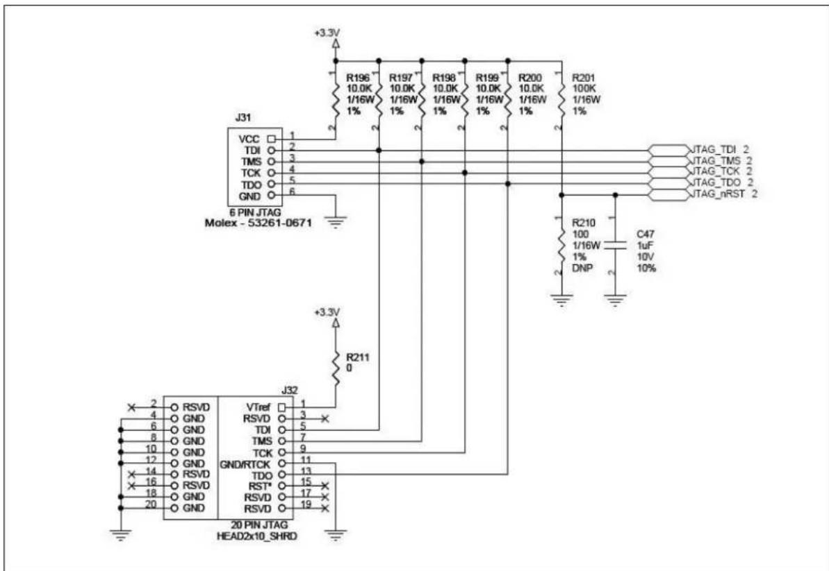
FIGURE 3-1: 6-PIN TO 20-PIN ADAPTER BOARD (W/ BOM)
text_image
+3.3V J31 VCC 1 TDI 2 TMS 3 TCK 4 TDO 5 GND 6 6 PIN JTAG Molex - 53261-0671 +3.3V R196 10.0K 1/16W 1% R197 10.0K 1/16W 1% R198 10.0K 1/16W 1% R199 10.0K 1/16W 1% R200 10.0K 1/16W 1% R201 100K 1/16W 1% R210 100 1/16W 1% DNP C47 1uF 10V 10% R211 0 +3.3V J32 X 2 O RSVD 4 O GND 6 O GND 8 O GND 10 O GND 12 O GND 14 O RSVD 16 O RSVD 18 O GND 20 O GND VTref 1 RSVD 3 TDI 5 TMS 7 TCK 9 GND/RTCK 11 TDO 13 RST* 15 RSVD 17 RSVD 19 20 PIN JTAG HEAD2x10_SHRDNote 1: The 10K pullups that are shown in Figure 3-1 are used on CEC1702 JTAG inputs to prevent them from floating when the JTAG cable is not attached.
2: The CEC1702 JTAG RST# pin connects to a 100K pullup to always enable the JTAG interface. Board design can provide pads for a pullup and pulldown for this pin in motherboard layout.
3: In order to prevent potential damage, use a keyed connector to avoid plugging the cable in backward which would result in a short between VTR and ground.
4: Add zero-ohm resistors to the JTAG link if there is a JTAG chain is used.
3.3.2 2-WIRE JTAG CONNECTION
Five signals are the minimum number required on the motherboard side; these are described in Table 3-2.
TABLE 3-2: CEC1702 2-WIRE JTAG PINS
| Name JTAG | Cable Connection |
| VTR The motherboard | VTR is always 3.3V. |
| SWDCLK Use on JTAG_CLK pin if selected. | |
| SWO | Use on JTAG_TDO pin if selected. |
| SWDIO | Use on JTAG_TMS pin if selected. |
| GND | Motherboard ground connect |
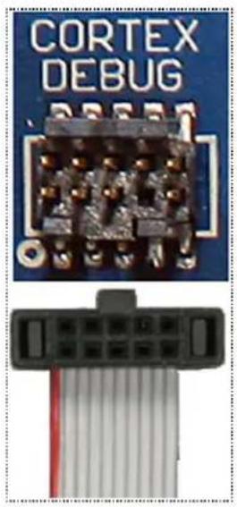
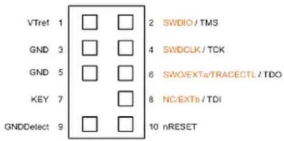
The Figure 3-2 shows the standard ARM Cortex 10 pins connector (a Samtec FTSH-105-01 w/ pin 7 removed).
FIGURE 3-2: 10-PIN CORTEX DEBUG (0.05") CONNECTOR
natural_image
Close-up of a blue circuit board labeled 'CORTEX DEBUG' and a black connector pin (no additional text or symbols visible)Cortex Debug
10-pin Connector
text_image
VTref 1 GND 3 GND 5 KEY 7 GNDDetect 9 2 SWDIO / TMS 4 SWDCLK / TCK 6 SWO/EXTa/TRACECTL / TDO 8 NC/EXTb / TDI 10 nRESET3.4 JTAG Internal Pull-Up
The firmware can select which debug pins to enable the internal pull-high. Default is disabled. Please see the CEC1702 Data Sheet DEBUG ENABLE REGISTER (4000_FC20h) for more information.
3.5 JTAG Reset
When the JTAG_RST# pin is not asserted (logic'1'), the JTAG_TDI, JTAG_TDO, JTAG_TCK, JTAG_TMS signal functions in the JTAG interface are unconditionally routed to the JTAG interface; the Pin Control register for these pins has no effect. When the JTAG_RST# pin is asserted (logic'0'), the JTAG_TDI, JTAG_TDO, JTAG_TCK, JTAG_TMS signal functions in the JTAG interface are not routed to the interface and the Pin Control Register for these pins controls the muxing. The pin control registers cannot route the JTAG interface to the pins. The system board designer should terminate this pin in all functional states using jumpers, pullup or pulldown resistors, and so forth.
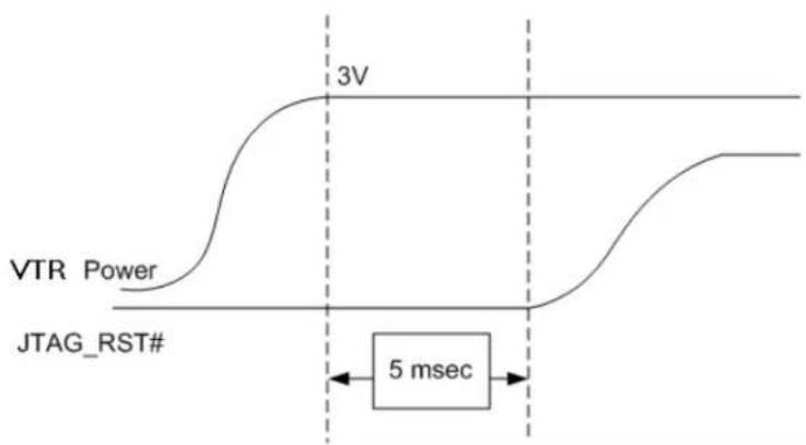
JTAG registers are set to their initial values by the assertion of the JTAG_RST# pin. The JTAG_RST# pin must be held low while the CEC1702 devices are powering up so the registers can be set to their proper default values. If JTAG_RST# is high during power up, the JTAG registers may be set to unpredictable values. This can trigger unwanted test modes and the system may not run correctly. As a result, the JTAG_RST# pin must be held low for at least 5.00 msec when applying VTR power.
Note: For more details on the JTAG_RST# pin, in particular JTAG_RST# functionality with respect to VTR power up events, as well as RESETI# reset input pin transitions, see the JTAG section in the CEC1702 Data Sheet.
The minimum required JTAG signals as shown in Table 3-1 does not include the JTAG_RST# signal. There are several options to handle the absence of this pin as followed:
• Production Mode with JTAG Port Disable:
- Hold the JTAG_RST# pin low with pulldown resistor to disable the JTAG port. Add a pullup resistor option (do not populate) for potential failure analysis to allow use of the JTAG interface. In this case, the JTAG_RST# pin must be manually held low at least 5.00 msec on power up.
• Production Mode with JTAG Port Enable:
- Add a jumper to hold the JTAG_RST# line low during power up, then remove the jumper in order to ensure that it meets the 5.00 msec timing requirement.
Optionally, put in hardware Resistor-Capacitor (RC) circuitry to force the JTAG_RST# signal low for at least 5.00 msec. For example:
- Use a CEC1702 EVB with external power supply which shows the rise time less than 100 s.
- RC = 100K ohms resistor pullup to VTR and 1μF capacitor.
- The rising timing of VTR related to the JTAG_RST# signal is shown in Figure 3-3; the falling time should be a reverse of the rising time.
Note: The RC values need to be changed in order to compensate for the power supply time to provide a 5.00 msec reset pulse, measured from VTR = 3.3V to JTAG_RST# = 0.8V.
FIGURE 3-3: VTR VS. JTAG RISING TIME
line
| Time Segment | Signal Type | | ------------ | --------------- | | Start | VTR Power | | Mid | 3V | | End | 5 msec |APPENDIX A: APPLICATION NOTE REVISION HISTORY
TABLE A-1: REVISION HISTORY
| Revision Section/Figure/Entry Correction | ||
| DS00002402D (05-04-21) Section 2.11, "Glitch Protection Pins" and Section 2.12, "Glitch on Reset!#" | Sections added. | |
| DS00002402C (10-24-19) Figure 1-5, "CEC1702 84-WFBGA Packing Routing Example" | Figure added. | |
| Section 2.5, "SPI Flash Implementation" | ||
| DS00002402B (03-09-18) Section 2.4, "ADC Input Layout Requirements for Regular Sampling" | Section modified, FIGURE 2-3: ADC Input Low Pass Filter on page 12 updated. | |
| DS00002402A (03-15-17) Initial Release. | ||
Note the following details of the code protection feature on Microchip devices:
• Microchip products meet the specifications contained in their particular Microchip Data Sheet.
• Microchip believes that its family of products is secure when used in the intended manner and under normal conditions.
- There are dishonest and possibly illegal methods being used in attempts to breach the code protection features of the Microchip devices. We believe that these methods require using the Microchip products in a manner outside the operating specifications contained in Microchip's Data Sheets. Attempts to breach these code protection features, most likely, cannot be accomplished without violating Microchip's intellectual property rights.
• Microchip is willing to work with any customer who is concerned about the integrity of its code.
- Neither Microchip nor any other semiconductor manufacturer can guarantee the security of its code. Code protection does not mean that we are guaranteeing the product is "unbreakable." Code protection is constantly evolving. We at Microchip are committed to continuously improving the code protection features of our products. Attempts to break Microchip's code protection feature may be a violation of the Digital Millennium Copyright Act. If such acts allow unauthorized access to your software or other copyrighted work, you may have a right to sue for relief under that Act.
Information contained in this publication is provided for the sole purpose of designing with and using Microchip products. Information regarding device applications and the like is provided only for your convenience and may be superseded by updates. It is your responsibility to ensure that your application meets with your specifications.
THIS INFORMATION IS PROVIDED BY MICROCHIP "AS IS". MICROCHIP MAKES NO REPRESENTATIONS OR WARRANTIES OF ANY KIND WHETHER EXPRESS OR IMPLIED, WRITTEN OR ORAL, STATUTORY OR OTHERWISE, RELATED TO THE INFORMATION INCLUDING BUT NOT LIMITED TO ANY IMPLIED WARRANTIES OF NON-INFRINGEMENT, MERCHANTABILITY, AND FITNESS FOR A PARTICULAR PURPOSE OR WARRANTIES RELATED TO ITS CONDITION, QUALITY, OR PERFORMANCE.
IN NO EVENT WILL MICROCHIP BE LIABLE FOR ANY INDIRECT, SPECIAL, PUNITIVE, INCIDENTAL OR CONSEQUENTIAL LOSS, DAMAGE, COST OR EXPENSE OF ANY KIND WHATSOEVER RELATED TO THE INFORMATION OR ITS USE, HOWEVER CAUSED, EVEN IF MICROCHIP HAS BEEN ADVISED OF THE POSSIBILITY OR THE DAMAGES ARE FORESEEABLE. TO THE FULLEST EXTENT ALLOWED BY LAW, MICROCHIP'S TOTAL LIABILITY ON ALL CLAIMS IN ANY WAY RELATED TO THE INFORMATION OR ITS USE WILL NOT EXCEED THE AMOUNT OF FEES, IF ANY, THAT YOU HAVE PAID DIRECTLY TO MICROCHIP FOR THE INFORMATION. Use of Microchip devices in life support and/or safety applications is entirely at the buyer's risk, and the buyer agrees to defend, indemnify and hold harmless Microchip from any and all damages, claims, suits, or expenses resulting from such use. No licenses are conveyed, implicitly or otherwise, under any Microchip intellectual property rights unless otherwise stated.
Trademarks
The Microchip name and logo, the Microchip logo, Adaptec, AnyRate, AVR, AVR logo, AVR Freaks, BesTime, BitCloud, chipKIT, chipKIT logo, CryptoMemory, CryptoRF, dsPIC, FlashFlex, flexPWR, HELDO, IGLOO, JukeBlox, KeeLoq, Kleer, LANCheck, LinkMD, maXStylus, maXTouch, MediaLB, megaAVR, Microsemi, Microsemi logo, MOST, MOST logo, MPLAB, OptoLyzer, PackeTime, PIC, picoPower, PICSTART, PIC32 logo, PolarFire, Prochip Designer, QTouch, SAM-BA, SenGenuity, SpyNIC, SST, SST Logo, SuperFlash, Symmetricom, SyncServer, Tachyon, TimeSource, tinyAVR, UNI/O, Vectron, and XMEGA are registered trademarks of Microchip Technology Incorporated in the U.S.A. and other countries.
AgileSwitch, APT, ClockWorks, The Embedded Control Solutions Company, EtherSynch, FlashTec, Hyper Speed Control, HyperLight Load, IntelliMOS, Libero, motorBench, mTouch, Powermite 3, Precision Edge, ProASIC, ProASIC Plus, ProASIC Plus logo, Quiet-Wire, SmartFusion, SyncWorld, Temux, TimeCesium, TimeHub, TimePictra, TimeProvider, WinPath, and ZL are registered trademarks of Microchip Technology Incorporated in the U.S.A.
Adjacent Key Suppression, AKS, Analog-for-the-Digital Age, Any Capacitor, AnyIn, AnyOut, Augmented Switching, BlueSky, BodyCom, CodeGuard, CryptoAuthentication, CryptoAutomotive, CryptoCompanion, CryptoController, dsPICDEM, dsPICDEM.net, Dynamic Average Matching, DAM, ECAN, Espresso T1S, EtherGREEN, IdealBridge, In-Circuit Serial Programming, ICSP, INICnet, Intelligent Paralleling, Inter-Chip Connectivity, JitterBlocker, maxCrypto, maxView, memBrain, Mindi, MiWi, MPASM, MPF, MPLAB Certified logo, MPLIB, MPLINK, MultiTRAK, NetDetach, Omniscient Code Generation, PICDEM, PICDEM.net, PICkit, PICtail, PowerSmart, PureSilicon, QMatrix, REAL ICE, Ripple Blocker, RTAX, RTG4, SAM-ICE, Serial Quad I/O, simpleMAP, SimpliPHY, SmartBuffer, SMART-I.S., storClad, SQI, SuperSwitcher, SuperSwitcher II, Switchtec, SynchroPHY, Total Endurance, TSHARC, USBCheck, VariSense, VectorBlox, VeriPHY, ViewSpan, WiperLock, XpressConnect, and ZENA are trademarks of Microchip Technology Incorporated in the U.S.A. and other countries.
SQTP is a service mark of Microchip Technology Incorporated in the U.S.A.
The Adaptec logo, Frequency on Demand, Silicon Storage Technology, and Symmcom are registered trademarks of Microchip Technology Inc. in other countries.
GestIC is a registered trademark of Microchip Technology Germany II GmbH & Co. KG, a subsidiary of Microchip Technology Inc., in other countries.
All other trademarks mentioned herein are property of their respective companies.
© 2017-2021, Microchip Technology Incorporated, All Rights Reserved.
ISBN: 9781522481409
For information regarding Microchip's Quality Management Systems, please visit www.microchip.com/quality.
Worldwide Sales and Service
AMERICAS
Corporate Office
2355 West Chandler Blvd.
Chandler, AZ 85224-6199
Tel: 480-792-7200
Fax: 480-792-7277
Technical Support:
http://www.microchip.com/
support
Web Address:
www.microchip.com
Atlanta
Duluth, GA
Tel: 678-957-9614
Fax: 678-957-1455
Austin, TX
Tel: 512-257-3370
Boston
Westborough, MA
Tel: 774-760-0087
Fax: 774-760-0088
Chicago
Itasca, IL
Tel: 630-285-0071
Fax: 630-285-0075
Dallas
Addison, TX
Tel: 972-818-7423
Fax: 972-818-2924
Detroit
Novi, MI
Tel: 248-848-4000
Houston, TX
Tel: 281-894-5983
Indianapolis
Noblesville, IN
Tel: 317-773-8323
Fax: 317-773-5453
Tel: 317-536-2380
Los Angeles
Mission Viejo, CA
Tel: 949-462-9523
Fax: 949-462-9608
Tel: 951-273-7800
Raleigh, NC
Tel: 919-844-7510
New York, NY
Tel: 631-435-6000
San Jose, CA
Tel: 408-735-9110
Tel: 408-436-4270
Canada - Toronto
Tel: 905-695-1980
Fax: 905-695-2078
ASIA/PACIFIC
Australia - Sydney
Tel: 61-2-9868-6733
China - Beijing
Tel: 86-10-8569-7000
China - Chengdu
Tel: 86-28-8665-5511
China - Chongqing
Tel: 86-23-8980-9588
China - Dongguan
Tel: 86-769-8702-9880
China - Guangzhou
Tel: 86-20-8755-8029
China - Hangzhou
Tel: 86-571-8792-8115
China - Hong Kong SAR
Tel: 852-2943-5100
China - Nanjing
Tel: 86-25-8473-2460
China - Qingdao
Tel: 86-532-8502-7355
China - Shanghai
Tel: 86-21-3326-8000
China - Shenyang
Tel: 86-24-2334-2829
China - Shenzhen
Tel: 86-755-8864-2200
China - Suzhou
Tel: 86-186-6233-1526
China - Wuhan
Tel: 86-27-5980-5300
China - Xian
Tel: 86-29-8833-7252
China - Xiamen
Tel: 86-592-2388138
China - Zhuhai
Tel: 86-756-3210040
ASIA/PACIFIC
India - Bangalore
Tel: 91-80-3090-4444
India - New Delhi
Tel: 91-11-4160-8631
India - Pune
Tel: 91-20-4121-0141
Japan - Osaka
Tel: 81-6-6152-7160
Japan - Tokyo
Tel: 81-3-6880-3770
Korea - Daegu
Tel: 82-53-744-4301
Korea - Seoul
Tel: 82-2-554-7200
Malaysia - Kuala Lumpur
Tel: 60-3-7651-7906
Malaysia - Penang
Tel: 60-4-227-8870
Philippines - Manila
Tel: 63-2-634-9065
Singapore
Tel: 65-6334-8870
Taiwan - Hsin Chu
Tel: 886-3-577-8366
Taiwan - Kaohsiung
Tel: 886-7-213-7830
Taiwan - Taipei
Tel: 886-2-2508-8600
Thailand - Bangkok
Tel: 66-2-694-1351
Tel: 43-7242-2244-39
Fax: 43-7242-2244-393
Denmark - Copenhagen
Tel: 45-4485-5910
Fax: 45-4485-2829
Finland - Espoo
Tel: 358-9-4520-820
France - Paris
Tel: 33-1-69-53-63-20
Fax: 33-1-69-30-90-79
Germany - Garching
Tel: 49-8931-9700
Germany - Haan
Tel: 49-2129-3766400
Germany - Heilbronn
Tel: 49-7131-72400
Germany - Karlsruhe
Tel: 49-721-625370
Germany - Munich
Tel: 49-89-627-144-0
Fax: 49-89-627-144-44
Germany - Rosenheim
Tel: 49-8031-354-560
Israel - Ra'anana
Tel: 972-9-744-7705
Italy - Milan
Tel: 39-0331-742611
Fax: 39-0331-466781
Italy - Padova
Tel: 39-049-7625286
Netherlands - Drunen
Tel: 31-416-690399
Fax: 31-416-690340
Norway - Trondheim
Tel: 47-7288-4388
Poland - Warsaw
Tel: 48-22-3325737
Romania - Bucharest
Tel: 40-21-407-87-50
Spain - Madrid
Tel: 34-91-708-08-90
Fax: 34-91-708-08-91
Sweden - Gothenberg
Tel: 46-31-704-60-40
Sweden - Stockholm
Tel: 46-8-5090-4654
UK - Wokingham
Tel: 44-118-921-5800
Fax: 44-118-921-5820