EVB-USB2502 - Unspecified Microchip - Free user manual and instructions
Find the device manual for free EVB-USB2502 Microchip in PDF.

User questions about EVB-USB2502 Microchip
0 question about this device. Answer the ones you know or ask your own.
Ask a new question about this device
Download the instructions for your Unspecified in PDF format for free! Find your manual EVB-USB2502 - Microchip and take your electronic device back in hand. On this page are published all the documents necessary for the use of your device. EVB-USB2502 by Microchip.
USER MANUAL EVB-USB2502 Microchip
EVB-USB2502 Evaluation Board Revision C
natural_image
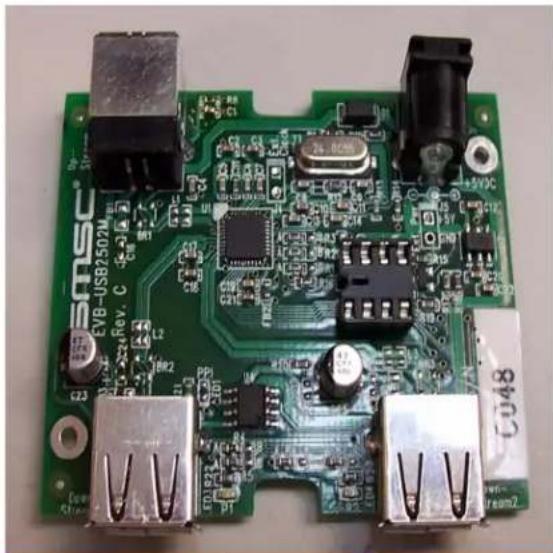
Close-up of a green printed circuit board with various electronic components and connectors (no readable text or symbols)Copyright © 2006 SMSC or its subsidiaries. All rights reserved.
The information contained herein is proprietary to SMSC and shall be used solely in accordance with the agreement pursuant to which it is provided. Although the information is believed to be accurate, no responsibility is assumed for inaccuracies. SMSC reserves the right to make changes to this document and to specifications and product descriptions at any time without notice. Neither the provision of this information nor the sale of the described semiconductor devices conveys any licenses under any patent rights or other intellectual property rights of SMSC or others unless specifically specified otherwise. The product may contain design defects or errors known as anomalies, including but not necessarily limited to any which may be identified in this document, which may cause the product to deviate from published specifications. SMSC products are not designed, intended, authorized or warranted for use in any life support or other application where product failure could cause or contribute to personal injury or severe property damage. Any and all such uses without prior written approval of an officer of SMSC will be fully at the risk of the customer. SMSC is a registered trademark of Standard Microsystems Corporation ("SMSC").
SMSC DISCLAIMS AND EXCLUDES ANY AND ALL WARRANTIES, INCLUDING WITHOUT LIMITATION ANY AND ALL IMPLIED WARRANTIES OF MERCHANTABILITY, FITNESS FOR A PARTICULAR PURPOSE, TITLE, AND AGAINST INFRINGEMENT AND THE LIKE, AND ANY AND ALL WARRANTIES ARISING FROM ANY COURSE OF DEALING OR USAGE OF TRADE. IN NO EVENT SHALL SMSC BE LIABLE FOR ANY DIRECT, INCIDENTAL, INDIRECT, SPECIAL, PUNITIVE, OR CONSEQUENTIAL DAMAGES; OR FOR LOST DATA, PROFITS, SAVINGS OR REV-ENUES OF ANY KIND: REGARDLESS OF THE FORM OF ACTION, WHETHER BASED ON CONTRACT; TORT; NEGLIGENCE OF SMSC OR OTHERS; STRICT LIABILITY; BREACH OF WARRANTY; OR OTHERWISE; WHETHER OR NOT ANY REMEDY OF BUYER IS HELD TO HAVE FAILED OF ITS ESSENTIAL PURPOSE, AND WHETHER OR NOT SMSC HAS BEEN ADVISED OF THE POSSIBILITY OF SUCH DAMAGES.
1 Overview
EVB-USB2502 Revision C Evaluation Board for the SMSC USB2502 USB2.0 Compatible 2-port Hub.
1.1 Features
■ USB 2.0 high-speed support with two down-stream ports
- Operates from a single voltage (+5.0V, regulated) 'wall wart' external power supply
■ Low Cost 2-Layer Design
■ Self or bus-powered operation
■ Overcurrent protection and port power switching (ganged mode)
■ Green LED port indicators
■ Single Onboard +3.3V Regulator
■ Optional ESD and EMI footprints are provided
■ Optional port power LED indicators
■ Optional serial EEPROM for configuration in a socket for easy programming
1.2 General Description
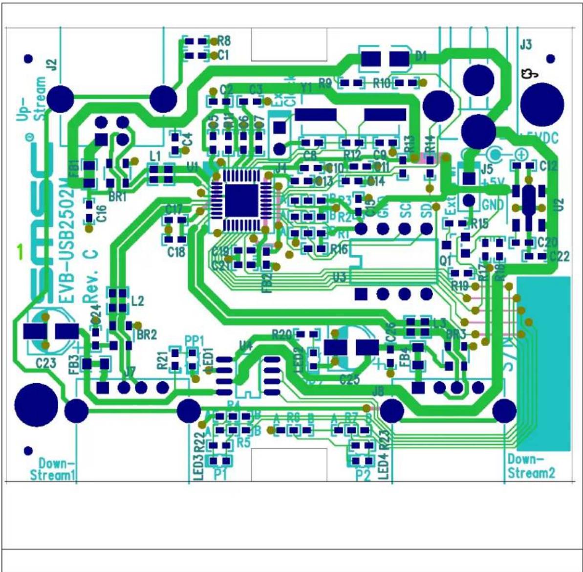
The EVB-USB2502 is a demonstration and evaluation platform featuring the USB2502 2-port USB2.0 Hub. It is configured with strapping options without using an EEPROM. The EVB-USB2502 can operate in self-powered mode when the external power supply is attached or in bus-powered mode when the external supply is detached or not connected to the wall. Strapping options and configuration can be changed by moving strapping resistors to different locations on the PCB. Footprints are available for optional features such as ESD protection, EMI filtering and LED indicators. A socket is provided for an external EEPROM. Figure 1 shows the top level silk screen and copper layer.
text_image
J2 Up- Stream EVB-USB2502M Rev. C 1 Down- Stream1 C23 FB3 L2 BR2 C16 C17 C18 L1 U1 C4 C2 C3 Y1 R9 R10 D1 J3 S VDC J5 +5V GND R15 C20 C22 Q1 R19 R17 R16 SC SD Ext R14 R13 R12 C9 Q11 R10 C8 Q13 R13 C7 Q14 R12 C7 Q15 R11 C6 Q16 R10 C5 Q17 R9 R10 C4 Q18 R8 C1 L3 R20 C25 J8 A R6 B A R7 B LED3 R22 R5 P1 P2 LED4 R23 P2 Down- Stream2Figure 1 Top level silk screen and copper layer
2 Getting Started
The EVB-USB2502 is configured by internal default and external strapping resistors. In this configuration it can operate as a generic self or bus-powered USB 2.0 hub with SMSC standard VID/PID/DID settings.
2.1 Configuration
The SMSC USB2502 is configured at the rising edge of RESET_N by sampling the state of pins CFG_SEL1 and CFG_SEL0. Selective populating resistor locations R1A, R1B, R2A and R2B determines the configuration source: internal default with strapping choice, SMBus or external EEPROM. Table 2.1 shows how to select the configuration source.
Table 2.1 Configuration Source Selection - resistor values in Ohms
| Configuration Source R1A R1B | R2A R2B | |||
| Strapping with internal defaults | 10k None | 10k None | ||
| EEPROM None 10k 10k None | ||||
| SMBus 10k None None 10k |
2.1.1 Configuration source - Internal default with strapping choice
The internal default sets Vendor ID, Product ID and Device ID and a few other choices. External strapping choices can be selected if the hub is part of a compound device to declare one or more down-stream port(s) as non-removable. A generic hub has both down-stream ports declared removable. The straps are selected via resistors connected to pins NON_REM1 and NON_REM0. Table 2.2 describes the choices.
Table 2.2 Non-removable port Selection - resistor values in Ohms
| Removable down-stream ports | R4A R4 | B R5A | R5B R6A | R6B R7A | R7B | |||
| Both down-stream ports are removable | 0 | None | 330 | None | 0 | None | 330 | None |
| Down-stream port 1 is non-removable (compound device) | None | 0 | None | 330 | 0 | None | 330 | None |
| Both down-stream ports are non-removable (compound device) | None | 0 | None | 330 | None | 0 | None | 330 |
| Determined by EEPROM or SMBus configuration | None | 0 | None | 330 | None | 0 | None | 330 |
2.1.2 Configuration source - External EEPROM
The EVB-USB2502 provides an 8-pin DIP socket IC U3 for an external EEPROM of type 24C00/01/02 to customize the hub settings. The EEPROM contains 16 bytes of user customizable settings. Among the settings are Vendor ID, Product ID, and Device ID numbers. For details on the fields please see the data sheet for the SMSC USB2502. Note that strapping options do not have any effect when using EEPROM. Setting down-stream ports to be removable or non-removable is also done in a field in the EEPROM.
2.1.3 Configuration source - SMBus
The EVB-USB2502 can be configured via a cable connected to the socket U3 by an external SMBus host. The SMBus cable connects to socket pins 5 (SDA), 6 (SCLK) and 7 (GND). All the customizable settings are accessible through the SMBus. For details on the fields please see the data sheet for the SMSC USB2502.
3 Optional Features
The EVB-USB2502 printed circuit board has three non-populated options: Indicators, ESD protection and EMI filtering. These options can be populated for further evaluation. The EMI filtering options requires cuts in PCB traces to break bypass connections on the PCB.
3.1 Option - Indicators
There are two LED indicators for port power on status. These indicators are single color LEDs that require external 330 Ohm series resistors.
3.2 Option - ESD protection
The EVB-USB2502 has locations for three diode bridge devices to protect the USB signal lines from ESD events. Each bridge also needs a 100nF capacitor populated on a location nearby.
3.3 Option - EMI filter
There are two levels of EMI filtering. Each level requires cuts on the PCB to remove the bypass connection. The first level are ferrite beads in the VBUS path for each down-stream port and the upstream port. The second level of filtering is a common mode choke placed in series of the three pairs of USB signals.