Supra Eco 3 - Pump Baracuda - Free user manual and instructions
Find the device manual for free Supra Eco 3 Baracuda in PDF.

User questions about Supra Eco 3 Baracuda
0 question about this device. Answer the ones you know or ask your own.
Ask a new question about this device
Download the instructions for your Pump in PDF format for free! Find your manual Supra Eco 3 - Baracuda and take your electronic device back in hand. On this page are published all the documents necessary for the use of your device. Supra Eco 3 by Baracuda.
USER MANUAL Supra Eco 3 Baracuda
natural_image
Technical line drawing of an electric motor with attached coil and power outlet (no text or symbols)Table of Contents
Section 1. Important Safety Instructions.....3
Section 2. Installation....7
2.1 Location Requirements....7
2.2 Hydraulic Connections....7
2.3 Electrical Connection 8
Section 3. Operation....8
3.1 Operating Principle......8
3.2 Operating the Pump 8
3.3 User Interface....9
3.4 Pump Speeds 9
3.5 Pump Shutdown and Reset....10
3.6 Priming the Pump 10
Section 4. Maintenance....10
4.1 Routine Maintenance.....10
4.2 General Maintenance Information ..... 11
4.3 Winterising....11
4.4 Servicing 12
Section 5. Repair Parts ....12
Section 6. Troubleshooting....13
6.1 Appliance Behaviour....13
6.2 Error Codes....14
Section 7. Pump Parts....15
Section 1. Important Safety Instructions
WARNING
READ AND FOLLOW ALL INSTRUCTIONS
All electrical work must be performed by a licensed electrician and conform to all national, state, and local codes. When installing and using this electrical equipment, basic safety precautions should always be followed, including the following:

RISK OF SUCTION ENTRAPMENT HAZARD, WHICH, IF NOT AVOIDED, CAN RESULT IN SERIOUS INJURY OR DEATH.
Do not block pump suction, as this can cause severe injury or death. Do not use this pump for wading pools, shallow pools, or spas containing bottom drains, unless the pump is connected to at least two (2) functioning suction outlets. Drain covers must be certified to the latest published edition of ANSI/ASME A112.19.8 or its successor standard ANSI/APSP-16. In Australia AS1926.3 is also an acceptable standard.
A check valve can interfere with the proper operation of certain Suction Vacuum Release System (SVRS) products. To avoid possible entrapment hazard, serious injury, or death, make sure to review the operation/owner's manual of your particular SVRS product before installing the check valve.
To reduce the risk of injury, do not permit children to use this product.
To reduce the risk of property damage or injury, do not attempt to change the backwash (multiport, slide, or full flow) valve position with the pump running.
Baracuda pumps are powered by a high-voltage electric motor and should be installed by a licensed or certified electrician or a qualified swimming pool service technician.
WARNING
BE SURE TO COMPLY WITH THE FOLLOWING SAFETY INSTRUCTIONS:
- Check all clamps, bolts, lids, lock rings, and system accessories to ensure they are properly installed and secured before testing.
- RELEASE ALL AIR in the system before testing.
- Water pressure for test must NOT EXCEED 250 KPA (35 PSI).
• Water temperature for test must NOT EXCEED 35°C (95°F). - Limit test to 24 hours. After test, visually check system to be sure it is ready for operation.
NOTICE: These parameters apply to Baracuda equipment only. For non-Baracuda equipment, consult the equipment manufacturer.
Chemical spills and fumes can weaken pool/spa equipment. Corrosion can cause filters and other equipment to fail, resulting in severe injury or property damage. Do not store pool chemicals near your equipment.
This pump is for use with permanently installed pools and may also be used with hot tubs and spas, if so marked. Do not use with storable pools. A permanently installed pool is constructed in or on the ground or in a building, such that it cannot be readily disassembled for storage. A storable pool is constructed so that it may be readily disassembled for storage and reassembled to its original integrity.
Do not install beneath the skirt of a hot tub. The pump requires adequate ventilation to maintain air temperature at less than the maximum ambient temperature rating listed on the motor rating plate.
Pump suction is hazardous and can trap and drown or disembowel bathers. Do not use or
WARNING
The following guidelines provide information for pump installation that minimizes risk of injury to users of pools, spas, and hot tubs:
Entrapment Protection - The pump suction system must provide protection against the hazards of suction entrapment.
Suction Outlet Covers - All suction outlets must have correctly installed, screw-fastened covers in place. All suction outlet (drain) covers must be properly maintained. They must be replaced if cracked, broken, or missing. Drain covers must be listed/certified to the latest published edition of ANSI®/ASME® A112.19.8 or its successor standard, ANSI/APSP-16. In Australia, AS1926.3 is also an acceptable standard. The pool must be shut down and bathers must be restricted from entering the pool until any cracked, broken, or missing drain covers are replaced.
Number of Suction Outlets Per Pump - Provide at least two (2) hydraulically-balanced suction outlets, with covers, as suction outlets for each circulating pump suction line. Connected suction points (outlets) shall not be less than 600mm apart where possible, centre to centre, and where not possible a minimum of 3 suction points (outlets) are required.
The system must be built to include at least two (2) suction outlets (drains) connected to the pump whenever the pump is running. However, if two (2) suction outlets run into a single suction line, the single suction line may be equipped with a valve that will shut off both suction outlets from the pump. The system shall be constructed such that it shall not allow for separate or independent shutoff or isolation of each drain. See Figure 1. Additional pumps can be connected to a single suction line as long as the requirements above are met.
Water Velocity - The maximum water velocity through the suction outlet assembly and its cover for any suction outlet must not exceed the suction outlet assembly and its cover's maximum design flow rate. The suction outlet (drain) assembly and its cover must comply

WARNING
FOR YOUR SAFETY
This product must be installed and serviced in accordance with the latest applicable version of AS/NZS 3000, along with any other applicable local and national installation codes/standards and any other local applicable regulations. Before installing this product, read and follow all warning notices and instructions that accompany this product.
Improper installation and/or operation will void the warranty.
Improper installation and/or operation can create unwanted electrical hazard which can cause serious injury, property damage, or death.
- Before handling the appliance, it is essential that you read this installation and user manual, as well as the "warnings and warranty" booklet delivered with the appliance. Failure to do so may result in material damage or serious or fatal injury and will void the warranty.
- Keep and pass on these documents for later viewing throughout the appliance's service life.
- The distribution or modification of this document in any way is prohibited, without prior authorisation from Baracuda.
- Baracuda is constantly developing its products to improve their quality. The information contained herein may therefore be modified without notice.

WARNING
- Failure to respect the warnings may cause serious damage to the pool equipment or cause serious injury, even death.
- The appliance is intended to be used only for swimming pools and spas; it must not be used for any purpose other than that for which it has been designed.
- This appliance is not intended for use by persons (including children) with reduced physical, sensory or mental capabilities, or lack of experience and knowledge, unless they have been given supervision or instruction concerning use of the appliance by a person responsible for their safety.
WARNING
- The power supply to the appliance must be protected by a dedicated 30 mA residual current device, complying with the standards and regulations in force in the country in which it is installed.
- Do not use and extension cord to plug the appliance into; plug it directly into a proper wall socket or outlet.
• Before carrying out any operations, check that: - The voltage indicated on the appliance information plate corresponds to the mains voltage,
- The power grid is adapted to the power requirements of the appliance and is properly grounded.
- The plug (where applicable) is suitable for the socket.
- In the event of abnormal operation or the release of odours from the appliance, turn it off immediately, unplug it from its power supply and contact a professional.
- Before any access to the appliance for any required service or maintenance, ensure that it is switched off and disconnected from the power supply.
- Do not disconnect and reconnect the appliance to the power supply when in operation.
- Do not pull on the power cord to disconnect it from the power supply.
- Do not attempt to carry out any service or maintenance with wet hands or while the appliance is wet.
- Clean the terminal board or the power supply socket before connection.
- For any component or sub-assembly containing a battery: do not recharge or dismantle the battery or throw it into a fire. Do not expose it to high temperatures or direct sunlight.
- In stormy weather, unplug the appliance to prevent it from suffering lightning damage.
- Do not immerse the appliance in water (with the exception of cleaners) or mud.
- This appliance is compatible with all types of water treatment used in swimming pools. Refer to the Baracuda warranty conditions for details of the permitted water balance values.
- Never run the pump dry or out of the water as this will void the warranty.
Section 2. Installation
2.2 Hydraulic Connections
- Check that the hydraulic corrections are correctly tightened and that there are no leaks.
- The pipes must be supported to prevent any risk of breakage due to the weight of the water.

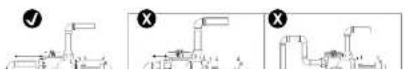
text_image
Technical diagram of a mechanical or electrical system with labeled components A, B, C, D and directional arrows indicating flow or movement.
Pump

Filter
© Heating system
D Water treatment system
Use as few elbow joints as possible. If there needs to be more than 10 elbow joints on the hydraulic circuit, increase the pipe diameter.
Section 3. Operation
WARNING
NEVER run pump dry! Running pump dry may damage seals, causing leakage and flooding! Fill pump with water before starting motor.
WARNING
Before removing lid:
STOP PUMP before proceeding.
CLOSE GATE VALVES in suction and discharge pipes.
RELEASE ALL PRESSURE from pump and piping system.
NEVER tighten or loosen screws while pump is operation.
WARNING
Do not block pump suction! To do so with body may cause severe or fatal injury. Children using pool must ALWAYS have close adult supervision!
3.1 Operating Principle
The filtration pump forms the core of the pool and is essential as it is used to circulate water through the pool's different components, in particular the filter.
Baracuda® SUPRA ECO 3 | Installation and Operating Instructions
- Check that the pump is stable and level.
- The hydraulic circuit must be bled and not contain any foreign bodies.
- The pump pre-filter strainer cover must be correctly closed (by hand) and its gasket clean and in place.
- Check that the valves are open.
- Start up the pump by activating a speed. The pump always starts in "priming" mode (2850 rpm for approx. 2 minutes).
- The pump is self-priming. However, you are strongly recommended to fill the pre-filter strainer with water before starting it up for the first time to facilitate the procedure.
- The pump has a priming capacity up to 3 metres above the swimming pool water level and at sea level elevation (if the hydraulic circuit is perfectly sealed).
- Bleed any air present in the filtration circuit using the bleed normally present on the filter (refer to the swimming pool filter's manual).
- Check that there are no leaks on the hydraulic circuit.
• This pump is rated to a maximum head of 16.5m
3.3 UserInterface
| Button Designation | |
| ECO | KEY "ECO" speed activation |
| LED Flashing: in priming mode (approx. 2 minutes on start-up) | |
| MED | KEY "MED" speed activation |
| LED Flashing: in priming mode (approx. 2 minutes on start-up) | |
| ...... | KEY "HIGH" speed activation |
3.5 Pump Shutdown and Reset
3.5.1 Pump Shutdown
- Press the STOP button.
3.5.2 Pump Reset
You may reset the pump to return it to "factory" configuration:
- Make sure that the pump is powered up but stopped ("OFF" is displayed on the screen).
- Press ECO + MED + HIGH for 5 seconds until the 3 corresponding LEDs flash once.
- Release the keys: the pump is now reset.
3.6 Priming the Pump
- Release all air from filter and piping system: see filter owner manual.
- In a flooded suction system (water source higher than pump), pump will prime itself when suction and discharge valves are opened.
- If pump is not in a flooded suction system, unscrew and remove lid cover; fill housing and pump with water.
- Clean lid and inspect housing; re-install on lid cover. Replace lid cover on housing; turn clockwise to tighten cover.
Section 4. Maintenance
WARNING
Switch the pump off before doing any maintenance, cleaning or other work.
Only perform maintenance/care work that is mentioned in the instruction manual.
4.1 Routine Maintenance
The only routine maintenance needed is inspection/cleaning of leaf basket. Debris or trash that collects in basket, will block off water flow through the pump.
- Make sure that the pump and electrical compartment contain no foreign bodies.
- Clean the outside of the appliance, do not use solvent-based products.
- Clean the pre-filter strainer, the cover and the gasket regularly.
- Check that the pre-filter strainer is correctly in place, or it may prevent the cover from closing fully.
Follow instructions below to clean leaf basket:
- Class number class set value in equation and
4.2 General Maintenance Information
- All other work must be performed by a qualified person.
- In the interest of safety and reliability, only use genuine Baracuda spare parts, in the event that pirate spare parts are used, the warranty will become null and void.
- Never run the pump dry, i.e. without water in pump wet end, as this will damage the pump.
- It is important to clean the pump leaf basket regularly.
- Clean plastic parts with a damp cloth. Cleaning agents can cause damage to the plastic parts.
- Do not spray down the electrical components with water.
- The pump is equipped with a thermal overload protection. If overload occurs during operation, the built-in overload protection automatically deactivates the pump. The pump will switch on automatically after a cooling period of approximately 20 (twenty) minutes. Ensure the cause of the overload is identified and addressed. If the pump remains on a continuous locked situation causing thermal overload, the motor may eventually damage and burn out.
These include:
- Damage to the motor, due to untimely or inadequate maintenance or cleaning of the cooling fan cover.
- Corrosive or other damage caused by incorrect storage of chemicals in pump enclosure.
- Damage due to the use of spare parts which are not original Baracuda parts.
- Damage due to maintenance and repair work not carried out by qualified technicians.
- To avoid personal injury do not have the pool pump running whilst there are people in the pool/spa.
4.3 Winterising
WARNING
The pump must be fully winterised in the event of a risk of frost or extended electrical disconnection. If the pump freezes it may cause severe damage and invalidate the warranty.
To avoid damaging the appliance with condensation, do not fully cover it.
4.4 Servicing
WARNING
It is recommended that the appliance undergo general servicing at least on a yearly basis to ensure proper operation, maintain performance levels and potentially prevent certain failures. These operations are carried out at the user's expense and certain operations must be performed by a technician.
Maintenance to be carried out by a qualified technician:
- Check the connection of the metal masses to the earth.
- Check that the electrical cables are correctly tightened and connected and that the switch box is clean.
- Check that the user interface is correctly connected.
Section 5. Repair Parts
Refer all service to your local agent or dealer as their knowledge of your equipment makes them the best qualified source of information.
Order all repair parts through your dealer.
Give the following information when ordering repair parts:
Section 6. Troubleshooting
- If a problem occurs, before you contact your retailer, please carry out these few simple checks using the following tables.
- If the problem continues, contact your retailer.
- Actions to be performed by a qualified technician only
6.1 Appliance Behaviour
| Problem Solution | |
| The pump does not start / the motor does not turn. | · Filtration outside of a scheduled operating range (“Auto” mode).Check the filtration clock settings.· Faulty user interface fuse, replace.· Electric power cut. Check the circuit breaker(s).· Check the connection between the power cable and the motor terminals.· Check that the user interface cable is not damaged.· The “error” light flashes, see “Error codes” Section.· Check that the motor shaft rotates freely. Check that there is no debris in the pre-filter strainer.· If debris remains, remove the pump to access the turbine. |
| The pump doesn’t prime / air can be seen in the pre-filter strainer. | · Check the position of all valves in the hydraulic circuit.· Air is stuck in the circuit, drain the hydraulic circuit (drain screw on the filter).· The pool’s water level is too low, air is being sucked into the circuit, fill the pool.· The gasket of the pre-filter strainer lid is defective, check the condition of the gasket and the correct airtightness of the lid. |
| Low flow rate/low filter pressure | · Pre-filter basked full of debris: clean.· Air leak in the circuit. Check all tightening torques.· The turbine and the pump diffuser are blocked or worn, replace. |
6.2 Error Codes
The interface control panel has a digital display and red error display LED to indicate operation issues. Normal operation is indicated by a single flash of this LED upon startup.
Any subsequent blink sequence of this LED indicates that a fault has been registered by the motor control, with the explanation of these faults given in the below table. This table also includes the cause for this fault as well as some potential actions to potentially resolve the issue.
| Blinks/ Display | Fault Software Cause Action | ||
| 1/ Er01 | Micro controller failure | Micro controller is continually rebooting. | No action can be taken to resolve issue.Return motor for warranty. |
| 2/ Er02 | Under voltage | The line voltage has dropped below 180 volts AC running. | The controller will reboot after voltage comes above 209 volts AC for at least 6 seconds.Reduce distance between motor/pump and breaker.Turn off any other non-critical equipment on the same breaker circuit. |
| 3/ Er03 Temperature | Temperature | Internal electronics detected an over temperature condition (+100°C on sensor) | Verify the proper impeller has been applied (net 1.0 Hp max).Turn the power off at the timer / breaker and allow motor to remain off for at least 15 minutes before reapplying power. |
| 4/ Er04 | Over current trip | Over current protection has tripped. | Verify the proper impeller has been applied (net 1.0 Hp max).Inspect all equipment / piping in the system connected to the pump. |
Section 7. Pump Parts
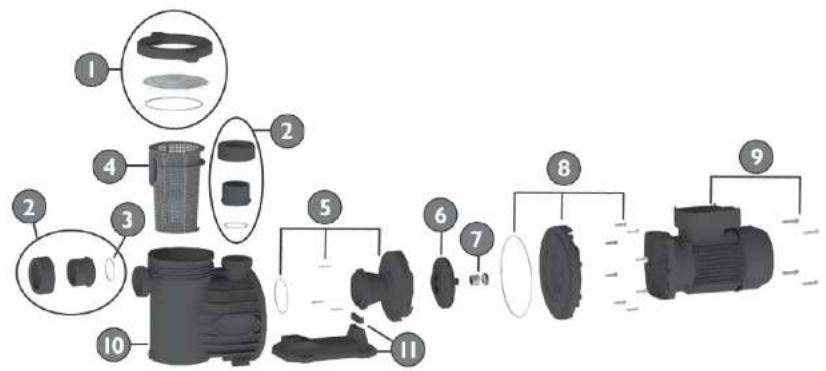
text_image
Exploded diagram of a camera assembly with numbered parts and component layouts| No | Component Part No | Description Qty | |
| 1 | 500-6441 Pump Lid Assembly 1 | ||
| 2 | 110-5173 Pump Union Complete AUS 40mm / 50mm 2 | ||
| 3 | 110-5123 Pump Union O-ring 2 | ||
| 4 | 500-5031 Pump Basket 1 | ||
| 5 | 500-5442 Pump Diffuser Assembly 1 | ||

For full warranty terms and conditions and to register your warranty, visit https://warranty.baracuda.com.au/ and complete your details. Or scan the QR code to go directly to the registration page
Record your equipment details here for quick reference:
Model No.:
Serial No.: ____

H0766100