MT34-1W - Fridge Beverage-Air - Free user manual and instructions
Find the device manual for free MT34-1W Beverage-Air in PDF.

User questions about MT34-1W Beverage-Air
0 question about this device. Answer the ones you know or ask your own.
Ask a new question about this device
Download the instructions for your Fridge in PDF format for free! Find your manual MT34-1W - Beverage-Air and take your electronic device back in hand. On this page are published all the documents necessary for the use of your device. MT34-1W by Beverage-Air.
USER MANUAL MT34-1W Beverage-Air
text_image
BEVERAGE-AIRBEVERAGE-AIR
INSTALLATION AND OPERATING INSTRUCTIONS for all Hydrocarbon MT Refrigerator and Freezer Models
natural_image
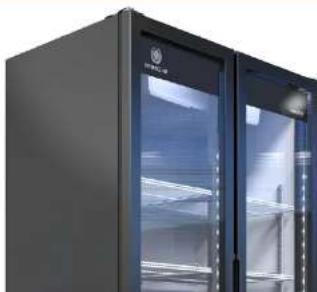
Exterior view of a modern black refrigerator with glass doors and side shelves (no visible text or symbols)User Manual for MT Refrigerators and Freezers Beverage-Air
WELCOME
Thank you for purchasing a Beverage-Air cabinet. This series has passed our strict quality control inspection and meets the high standards set by Beverage-Air! You have made a quality investment that with proper maintenance will give you many years of reliable service!
Please read the following installation and maintenance instructions before installing or using your unit. If you have any questions, Please call our Technical Service Department at (800) 684-1199. 8:00 AM to 5:00 PM EST.
Important Information
- PLEASE READ THESE INSTRUCTIONS CAREFULLY BEFORE INSTALLING OR USING, IF RECOMMENDED PROCEDURES ARE NOT FOLLOWED, WARRANTY CLAIMS MAY BE DENIED.
- Your warranty registration information is located with this manual. Please complete the card and submit it to Beverage-Air within TEN days of installation. Failure to properly register equipment may limit or void the warranty.
- Beverage-Air reserves the right to change specifications and product design without notice. Such revisions do not entitle the buyer to corresponding changes, improvements, additions, or replacements for previously purchased equipment. Owner is not entitled to alter or modify equipment in any way without manufacturer's approval.
Safety 3
Important Information ....4
Product Information 5
Clearance and Displacement
User Manual for MT Refrigerators and Freezers Beverage-Air
SAFETY
When using electrical appliances, basic safety measures should always be taken. This appliance has been designed with your safety in mind. It has many features to keep you from being harmed. However, safe operation and maintenance are your responsibilities.

CAUTION
Use: When using this unit, please:
- Move it carefully. If on casters be sure the casters do NOT run over the power cord.
- Lock the casters when in use.
- Seek help. This machine is heavy! Be sure to move with enough help to avoid tipping or dropping the cabinet Use care when moving or handling this equipment. It is equipped with flammable refrigerant. Damage to refrigerant tubing will increase the risk of a leak

CAUTION
Maintenance
Do NOT:
- Clean a frozen evaporator with a sharp object
- Clean a dirty condenser with a sharp object.
-
Store gasoline, kerosene or any other flammable material near the cabinet.
-
Prevent children from playing in or on the cabinet. Do not allow children to climb on or around equipment. Persons unable to use this product must be prevented access.
- Follow all manufacturers instructions. There are many safety labels and directions on the unit. Heed them.
- Watch your fingers. There may be pinch points near the door hinges.
Do ALWAYS
- Use a Beverage-Air recommended technician certified to repair R-290 or R-600 equipment. Seek factory authorized technicians trained to safely maintain and service systems that utilize these flammable refrigerants. RSES offers training and certification.
- Use ONLY Beverage-Air factory authorized replacement parts. Use of non OEM parts can be dangerous because of the design changes needed to safely use R-290 or R-600.
User Manual for MT Refrigerators and Freezers Beverage-Air
IMPORTANT INFORMATION
This unit is intended to be used in a commercial application. That includes bars and restaurants.
If installed in a residence, some commercial service companies may not be able to service it on site.
The manufacturer has designed and produced this machine with the finest in materials. The manufacturer assumes no liability for units that have been altered in any way. Alterations or part substitutions will void the warranty.
Limitations
The machine is designed for use indoors in a controlled environment. It must be kept dry, not overheated or subjected to excessive cold. May only be connected to a dedicated electrical circuit. Extension cords are not permitted.
| Minimum | Maximum | |
| Voltage | 100 | 130 |
| Room Air Temp | 75.2°F | 100°F |
Air Flow, All Models regardless of sections, or door count.
natural_image
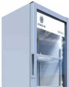
Exterior view of a modern stainless steel refrigerator with glass doors (no visible text or symbols)User Manual for MT Refrigerators and Freezers Beverage-Air
PRODUCT INFORMATION
| Model | Cabinet Dimensionsw x d x h (Inches) | Sections | Full LoadAmps | Power Cord Plug(NEMA) | Refrigerant Type / Charge(g) / Charge (oz) |
| REFRIGERATOR MODELS | |||||
| MT06 21 1/4 X 27 3/4 | X 36 1/4 1 2.5 | 5-15P R | 600 / * | ||
| MT08 18 7/8 X 20 5/8 | X 71 3/8 1 1.8 | 5-15P R | 600 / 45 / 1.52 | ||
| MT10 24 7/8 X 22 13/ | 16 X 54 3/8 1 3.2 | 5-15P R | 290 /47 / 1.59 | ||
| MT12 24 7/8 X 22 9/16 | X 63 1/4 1 | 4.1 | 5-15P | R-290 /55 / 1.86 | |
| MT21 39 1/8 X 24 1/2 | X 61 7/32 2 | 3.6 | 5-15P | R-290 /65 / 2.2 | |
| MT23 | 29 1/2 X 25 13/16 X 78 5/16 | 1 | 7.0 | 5-15P | R-290 /55 / 1.86 |
| MT34 | 39 1/2 X 27 1/2 X 79 | 2 76 | 5-15P | R-290 /60 / 2.03 | |
| MT41-48 | 47 1/4 X 21 3/4 X 48 1/8 | 2 | 3.1 | 5-15P R | 290 / 50 / 1.69 |
| MT41-54 | 47 1/4 X 21 3/4 X 54 | 2 | 3.1 | 5-15P R | 290 / 50 / 1,69 |
| MT49 | 47 1/8 X 29 3/16 X 78 3/8 | 2 | 8.3 | 5-15P | R-290 /95 / 3.21 |
| MT49-SD | 47 1/8 X 29 1/4 X 78 3/8 | 2 | 8.3 | 5-15P | R-290 /85 / 2.87 |
| MT53 54 1/4 X 29 1/8 | X 78 3/8 2 | 8.7 | 5-15P | R-290 /95 / 3.21 | |
| MT53-SD | 54 1/4 X 28 9/16 X 78 3/8 | 2 | 8.7 | 5-15P | R-290 /95 / 3.21 |
| MT72 | 78 3/4 X 33 5/8 X 79 | 3 | 13.6 | 5-15P | R-290 / 160 / 5.41 |
| FREEZER MODELS | |||||
| MTF23 | 30 1/8 X 30 7/8 X 78 3/4 | 1 | 7.0 | 5-15P | R-290 /144.6 / 4.9 |
| MTF53* (2 systems) | 54 3/10 X 31 3/10 X 78 9/10 | 2 | 11.2 | 5-15P | R-290 /110.6 / 3.75 x 2 |
Height includes casters.
User Manual for MT Refrigerators and Freezers Beverage-Air
CLEARANCE AND PLACEMENT

text_image
Placement F1 H10000 1.54203 5.2420 F2 H10000 1.54203 5.2420 F3 H10000 1.54203 5.2420Consider the following when selecting a location for your unit:
User Manual for MT Refrigerators and Freezers Beverage-Air
UNPACKING AND SET UP
IMPORTANT: It is not recommended to use a box cutter or razor knife when uncrating product. The use of these items could damage components and or scratch equipment surface. If necessary, only use these items to make cuts where indicated on crating, and/or on the back of the product while considering all precautions about using sharp tools.
Carefully inspect the shipping carton for damage. This is the only time that shipping damage may be claimed. If damage is suspected, open the carton immediately and, if there is damage, retain the carton and contact the shipper to make a claim. Do NOT contact the manufacturer.
Uncrating
Tools Needed: Phillips screwdriver.

Risk of personal injury. Unit must be securely supported while attaching casters or legs.
- Cut the stretch wrap from any side, remove the cardboard from the corners, the cardboard top and the cardboard in the front and the back.
2 Remove the bond paper. Discard stretch wrap and any cardboard that will not be recycled.
3 Move unit as close to final position as possible before removing the skid.
Skid Removal
- Remove the shipping screws using the Phillips screwdriver while the cabinet is held in one direction. Repeat the process while the cabinet is held in the opposite direction.
2 When tilting the cabinet in one direction block it securely with pieces of 2x4 lumber or other suitable material.
3 Tip the unit to one side to remove the skid. Repeat this step for the other side

natural_image
Line drawing of a person standing beside a large refrigerator (no text or symbols)User Manual for MT Refrigerators and Freezers Beverage-Air
OPERATING EQUIPMENT
Operating Steps:
- Once equipment is in place, let stand for at least 12 hours to allow compressor oil to fully settle.
- Plug the unit into electrical outlet, following all previous instructions and electrical specifications.
- Avoid operating equipment with wet hands, or in standing water to avoid electrical hazard.
Temperature level adjustment knob
The ETC1H control in some models is also pre-configured by the manufacturer to maintain product temperature. It does not include a display that shows temperature or alarms. If you notice malfunctioning, please notify the Beverage-Air Technical Services Department.
Product Storage:
• Install shelves using metallic clips (make sure they are aligned at the same height).
- If the cooler has been turned off and it is necessary to turn it back on, wait at least one hour to cool the interior before reloading product.
- When the cooler is filled up, arrange and order product inside. Do not throw or drop product into the cabinet as it may damage the interior or shelving.
Air flow inside the cabinet is very important. Please make sure that:
- Product weight does not exert pressure on internal walls and product does not extend beyond perimeter of shelves.
- Avoid introducing products in closed boxes/cartons, trays, and/or bags sealed in plastic as it may affect actual product temperature.
- Keep products away from fan blades. Do not obstruct fan air inlets.
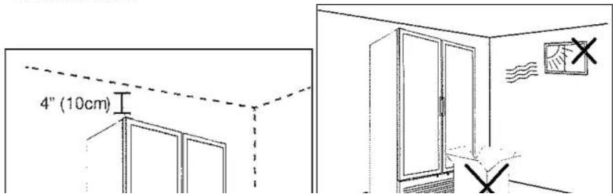
- Make sure there is at least 1" between product and shelf to allow proper air flow inside the cooler. Do not place product all the way back against the wall. The cooler comes with a wall separator to ensure that there is at least 1"
User Manual for MT Refrigerators and Freezers Beverage-Air
- Avoid installing this cooler in direct sunlight.
- Do not install this cooler outdoors.
- This cooler must not be used or stored where ambient temperature is under 14^ or greater than 140^ or where relative humidity is greater than 75% .
- Never install equipment close to heat sources to avoid excessive energy consumption or equipment malfunction.
- Do not introduce products into the equipment that are warmer than the ambient temperature. Do not install close to heat sources, otherwise, this may cause an inefficient cooler operation and will increase energy consumption.
- Do not place items in front of grille. This could obstruct air flow causing the product to operate inefficiently and increase energy consumption.
- Do not place objects or appliances on top of this equipment. The cabinet is constructed of laminate and polyethylene foam that may end or deform when hit or stressed.
- For proper operation, equipment must have a minimum distance of 4" (10 cm) from walls and other structures in the back and on both sides.
text_image
4" (10cm)User Manual for MT Refrigerators and Freezers Beverage-Air
SHELF INSTALLATION
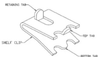
- Determine the proper location for the shelf clips. The reference numbers on the pilaster can serve as a guide to ensure all clips are properly located.
- Insert the top tab of the shelf clip into the desired hole of the pilaster. The retaining tab MUST be facing up as shown.
- Rotate the clip downwards and insert the bottom tab into the matching hole in the pilaster. The clip may need to be squeezed slightly during installation.
- Install all remaining clips.
-
Install shelves onto clips with the product retention bar facing up. Be careful not to dislodge clips during installation.
-
Place shelves so that the retaining tab on the clip captures the shelf as shown.
- Confirm that the shelf is resting on ALL 4 clips and that the clips are securely attached to the pilasters.
- Improper shelf clip installation could cause the shelf and / or the product on it to fall, resulting in damage to the unit and possible bodily injury.
- Do NOT overload the shelves. The unit is designed to use all shelves that are supplied in an equally spaced manner. Contact Beverage-Air customer service if fewer shelves or a different configuration to ensure shelf overloading will not occur.
text_image
RETAINING TAB SHELF CLIP TOP TAB BOTTOM TAB
text_image
TOP TAB FULLY INSERTED INTO SLOT BOTTOM TAB FULLY SEATED PROPERLY INSTALLED SLIP IMPROPERLY INSTALLED SLIP (UPSIDE DOWN)User Manual for MT Refrigerators and Freezers Beverage-Air
ELECTRICAL
This is a cord-connected unit, and must be connected to it's own dedicated power supply. Beverage Air coolers with HC refrigerants (R-290/R-600) are designed to operate at specific voltages. Prior to installation, check equipment serial number and the dataplate on the machine to confirm the voltage and per the dataplate use the correct fuses or HACR circuit breakers.
Note: Do not connect to GFI / GFCI outlets. Connection to that type of outlet can result in product loss due to unsafe cabinet temperature when GFI device trips from moisture.
IMPORTANT: ground connection is a protection system for equipment connected to an electrical network. It is used in electrical installations to avoid current pass-through to use, due to an isolation failure of active conductors. This cooler must be connected to a physical ground. In case a short circuit occurs, ground connection reduces the risk of electrical shock.
Power Cord
This 115 volt model is equipped with a polarized power cord with a grounded 5-15P connection plug. Do not attempt to eliminate the ground connection or use two-terminal adapters. Plug must be connected to an adequately-installed and grounded outlet. If the owner does not have this type of outlet, it is their responsibility to have one installed. Please contact a certified electrician or a certified technician if you have questions.
If the power cord becomes damaged, it must be replaced with the identical cord. Using extension cords will void the warranty.
Initial Start Up
Plug the power cord into the proper power supply. Connect the plug firmly into the electrical outlet making sure it is inserted properly.
The cabinet will soon begin to blow warm air out of the top area, and cool air will flow from the inside blower.
The cabinet temperature has been set at the factory and should not need adjustment, however if it was changed, the standard setting for refrigerators is 36.3°F for single door equipment and 35.4°F for two door equipment. The freezers will be set to 0°F at the factory, but the temperature for the freezers cannot be adjusted and must remain at 0°F.
User Manual for MT Refrigerators and Freezers Beverage-Air
CLEANING AND MAINTENANCE
Cleaning Schedule:
| CabinetDaily wipe downWeekly interior |
Condenser coil
| Monthly cleaning or as required |
Gaskets
| Daily inspection, check that hinges are tight to the cabinet. |
Routine maintenance
| Annually |
IMPORTANT:
Disconnect the cooler from wall outlet before you perform any maintenance or cleaning.
Always perform cleaning and maintenance tasks in a safe manner.
Do not clean equipment with a water hose or jet wash as it may cause damage to electrical components and cause electric shock. Do not use sharp objects during cleaning to remove excess dirt, use a brush if required. Do not use any solvents or abrasive products for cleaning tasks, this may damage surface finishing.
Daily Exterior Cleaning
It is much easier to clean on a regular basis than to have to remove stains once they have built up. Regular cleaning helps avoid deterioration and impedes malfunctioning which may alter product preservation.
-
Wash with a soft cloth, warm water, and a mild detergent that does not contain chlorine.
-
Polish with a soft cloth, wiping with the grain.
-
Rinse with clean water.
-
Wipe weekly with stainless steel cleaner.
-
Dry with a soft cloth.
-
Use a broom or dry mop to clean the area under the equipment. Avoid splashing water directly onto the front, or underneath the cooler.
User Manual for MT Refrigerators and Freezers Beverage-Air
Condenser Cleaning
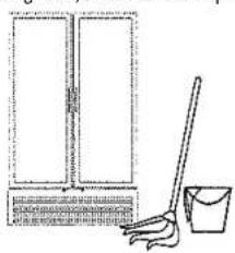
The condenser must be cleaned once a month, or when required to avoid dirt from reducing cooling system efficiency.
To clean the condenser, the front grille will need to be removed as shown in the illustration below.
Remove dust, lint, and debris with a soft bristle brush or broom.
In kitchens and/or cooking areas where grease may accumulate, the condenser may need to be cleaned with water and degreasing agent.
IMPORTANT: Do not use solvent or abrasive products for cleaning as they may damage the surface.
Do not use sharp pointed objects to remove grease, use a brush if required.

natural_image
Simple line drawing of a cabinet with a broom and bucket, no text or symbols present
natural_image
Diagram showing a cabinet with a gavel and a rack-mounted device, no text or symbols presentEvaporator Defrost
This product is equipped with an automatic evaporator defrost system to guarantee adequate interior air flow.
If you notice ice forming and/or equipment is not cooling properly, contact the Beverage Air Technical Service Center for assistance.
Plastic Evaporator Housing
- Unscrew the drain nut
Tube Cover
- Remove the grilles
User Manual for MT Refrigerators and Freezers Beverage-Air
METHODS FOR CLEANING STAINLESS STEEL
| Cleaning Needed Cleaning | Agent Method of Application Affect on Finish | ||
| Smears and fingerprints | Areal 20, Lac-O-Nu, Lumin Wash O'Cedar Cream Polish, Stainless Shine. | Rub with cloth as directed on the package. | Satisfactory for use on all finishes.Provides barrier film to minimize prints. |
| Stubborn Spots and Stains, Baked-On Splatter, and Other Light Discolorations | Allchem Concentrated Cleaner. | Apply with damp sponge or cloth.Rub with damp cloth. | Use in direction of polish lines on No. 4 (polished) finish. May scratch No. 2 (mill) and Nos. 7 and 8 (polished) finishes. |
| Samae, Twinkle or Cameo Copper Cleaner | Rub with damp cloth. | ||
| Grade FFF Italian pumice, whiting, or talc. | Rub with dry cloth. | ||
| Liquid NuSteelPaste NuSteel or DuBois Temp.Copper's Stainless Steel CleanerRevere Stainless CleanerHousehold cleansers, such as Old Dutch, Lighthouse, Sunbrite, Wyandotte, Bab-O, Gold Dust, Sapolio, Bon Ami, Ajax, or Comet Grade F Italian Pumice, Steel Bright, Lumin Cleaner, Zud, Restore, Sta-Clean, or Highlite.Penny-Brite or Copper-Brite. | Use small amount of cleaner.Rub with dry cloth using a small amount of cleaner.Apply with damp sponge or cloth.Rub with a damp cloth. May contain chlorine bleaches.Rinsethoroughly after use.Rub with a damp cloth.Rub with a dry cloth using a small amount of cleaner. | ||
| Heat tint or discoloration | Penny-Brite or Copper-Brite.Past NuSteel, DuBois Temp, or Tarnite. Revere Stainless Steel Cleaner. Allen Polish, Steel Bright, Tenacious Deposits,Rusty Discolorations, Industrial | Rub with a dry cloth.Rub with a dry cloth or stain-less steel wool.Apply with damp sponge or cloth.Rub with a damp cloth. | |
User Manual for MT Refrigerators and Freezers Beverage-Air
HELP
| Malfunction Possible Cause Likely Solution | ||
| No cooling - unit is silent Unit not plugged in. | Fuse or circuit breaker tripped.Power cord plug loose in outlet. | Connect to proper voltage circuit,Replace fuse or reset breaker,Check outlet for loose connection,replace as needed |
| Unit cools but runs constantly Dirty condenser. Clean the condenser | ||
| Internal temperature too high Dirty condenser.Evaporator iced over, or unit in high temperature environment. | Clean condenser, Defrost evaporator,Reduce ambient temperature around equipment | |
| Internal temperature too low, freezing product | Temperature control. Adjust or replace control | |
| Not cooling - compressor not on Temperature control stuck in open position. | Replace temperature control | |
| Not cooling - compressor hums but does not start | Low voltage to unit.Compressor starting system failure. | Check voltage, and correct as needed,Check start relay and start capacitor,See next step |
| Not cooling - compressor starts but doesn't stay on | Compressor start relay failure.Compressor start capacitor failure. | Replace relay or capacitor |
| Not cooling - compressor cycles on Over heating or weak overload. Clean condenser, check fan motor and blade. Check refrigerant charge, replace overload | ||
| Unit cools but turns on and off frequently | No product in cabinet. Temperature control defective. Refrigeration issue. | Fill cabinetReplace controlHave system checked |
| Excessive noise Tubing rattle. Loose parts, bent or broken fan blade, Noisy fan motor. | Check tubing for routing. Check for loose components, Replace fan blade,Replace fan motor | |
User Manual for MT Refrigerators and Freezers Beverage-Air
FOR THE SERVICE TECH R-290 AND R-600

text_image
WARNING Electric shock risk -Connect to a three-pin outlet -Do not remove outlet ground pin -Do not use power adapters -Do not use extension cords -If failure occurs when following these instructions, it may cause tire or electric shockRefrigeration service should only be attempted by a trained trade professional certified to work on R-290 or R-600 systems.
Here are some critical service items.
This list does not qualify anyone to service the unit. It is a reminder and checklist for the service tech. Keep these in mind for R-290 and R-600 service:
- Wire nuts are NOT to be used when changing an electrical part.
- The switches in this product are sealed, only exact replacements may be used.
- The process tubes are to be used for service access.
- Cut out (with tubing cutter) refrigeration components that are to be replaced. Do NOT un-braze.
- Because this refrigerant can be vented into the air during service, the venting MUST be in an area free from flame or spark. It must be near an opened
only way to ensure that the system is dry and ready for a charge of refrigerant.
Charging: The system is critically charged and the proper type and amount MUST be weighed in.
Overcharge symptoms: Unit will cool properly but the suction line temperature will be unusually cold. Compressor run time will be longer than normal.
Undercharge symptoms: Long run time, poor cooling and a hot compressor dome are the main symptoms of an undercharge.
Selected System Components and Definitions:
System - Hermetically sealed system that includes compressor, finned condenser, finned evaporator, and capillary tube metering device.
User Manual for MT Refrigerators and Freezers Beverage-Air
FOR THE SERVICE TECH · WIRING DIAGRAM FOR MT06

flowchart
graph TD
    A["POWER SUPPLY 115V / 60 HZ / I"] --> B["RED"]
    B --> C["POWER SWITCH"]
    C --> D["WHITE"]
    D --> E["OVERLOAD PROTECTOR"]
    E --> F["COMPRESSOR"]
    F --> G["PTC"]
    G --> H["RUN CAPACITOR"]
    H --> I["WHITE"]
    I --> J["CONDENSER FAN"]
    J --> K["MINI"]
    K --> L["BLUE"]
    L --> M["WHITE"]
    N["ELECTRONIC THERMOSTAT"] --> O["BLACK"]
    O --> P["2"]
    P --> Q["3"]
    Q --> R["M"]
    R --> S["S"]
    S --> T["C"]
    T --> U["2"]
    U --> V["3"]
    V --> W["4"]
    W --> X["5"]
    X --> Y["6"]
    Y --> Z["1"]
    Z --> AA["2"]
    AA --> AB["3"]
    AB --> AC["4"]
    AC --> AD["5"]
User Manual for MT Refrigerators and Freezers Beverage-Air
FOR THE SERVICE TECH - WIRING DIAGRAM FOR MT08
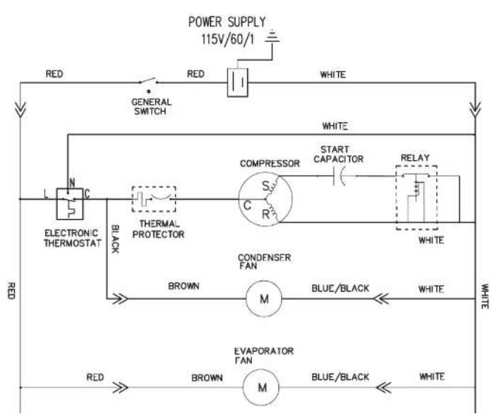
flowchart
graph TD
    A["POWER SUPPLY 115V/60V/1"] --> B["GENERAL SWITCH"]
    B --> C["THermal PROTECTOR"]
    C --> D["COMPRESSOR"]
    D --> E["START CAPACITOR"]
    E --> F["RELAY"]
    F --> G["CONDFENSER FAN"]
    G --> H["M"]
    H --> I["BLEU/BLACK"]
    I --> J["WHITE"]
    J --> K["EVAPORATOR FAN"]
    K --> L["M"]
    L --> M["BLUE/BLACK"]
    M --> N["WHITE"]
    N --> O["RED"]
    O --> P["BROWN"]
    P --> Q["BLACK"]
    Q --> R["L N C"]
    R --> S["RED"]
    S --> T["WHITE"]
    style A fill:#f9f,stroke:#333
    style T fill:#f9f,stroke:#333
User Manual for MT Refrigerators and Freezers Beverage-Air
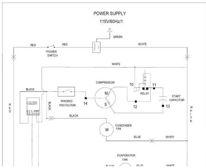
FOR THE SERVICE TECH - WIRING DIAGRAM FOR MT10

flowchart
graph TD
    A["POWER SUPPLY 115V/60Hz/1"] --> B["RED"]
    B --> C["*POWER SWITCH"]
    C --> D["RED"]
    D --> E["GREEN"]
    E --> F["WHITE"]
    F --> G["THermal Overload Protector"]
    G --> H["3"]
    H --> I["WHITE"]
    G --> J["COMPRESSOR"]
    J --> K["S M"]
    K --> L["START RELAY"]
    L --> M["3"]
    M --> N["4"]
    N --> O["2'"]
    O --> P["BLUE"]
    P --> Q["WHITE"]
    R["BLACK"] --> S["BLACK"]
    T["ELECTRONIC THERMAL/HT"] --> U["C L H N F 12 3 4 5 6"]
    V["CONDENSER FAN"] --> W["M"]
    X["WHITE"] --> Y["3"]
    Z["WHITE"] --> AA["1"]
    AB["WHITE"] --> AC["2"]
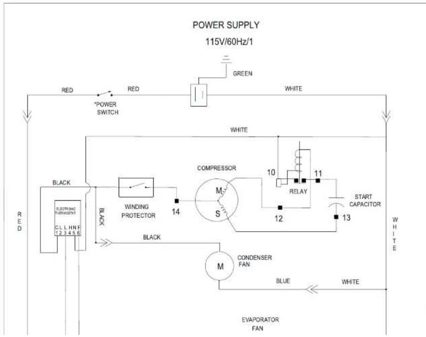
User Manual for MT Refrigerators and Freezers Beverage-Air
FOR THE SERVICE TECH - WIRING DIAGRAM FOR MT12
flowchart
graph TD
    A["POWER SUPPLY 115V/60Hz/1"] --> B["RED"]
    B --> C["*POWER SWITCH"]
    C --> D["GREEN"]
    D --> E["WHITE"]
    E --> F["BLACK"]
    F --> G["WINDING PROTECTOR"]
    G --> H["COMPRESSOR"]
    H --> I["RELAY"]
    I --> J["START CAPACITOR"]
    J --> K["CONDENSER FAN"]
    K --> L["BLUE"]
    L --> M["WHITE"]
    M --> N["EVAPORATOR FAN"]
    N --> O["BLACK"]
    O --> P["BLACK"]
    P --> Q["BLACK"]
    Q --> R["CCL HNF 123456"]
    R --> S["RED"]
User Manual for MT Refrigerators and Freezers Beverage-Air
FOR THE SERVICE TECH - WIRING DIAGRAM FOR MT23
flowchart
graph TD
    A["POWER SUPPLY 115V/60Hz/1"] --> B["RED"]
    B --> C["*POWER SWITCH"]
    C --> D["GREEN"]
    D --> E["WHITE"]
    E --> F["BLACK"]
    F --> G["WINDING PROTECTOR"]
    G --> H["COMPRESSOR"]
    H --> I["RELAY"]
    I --> J["START CAPACITOR"]
    J --> K["WHITE"]
    K --> L["CONDenser FAN"]
    L --> M["BLUE"]
    M --> N["WHITE"]
    N --> O["EVAPORATOR FAN"]
    O --> P["BLACK"]
    P --> Q["BLACK"]
    Q --> R["Electronic Thermostat 1.2 3 4 5 6"]
    R --> S["Black"]
User Manual for MT Refrigerators and Freezers Beverage-Air
FOR THE SERVICE TECH - WIRING DIAGRAM FOR MT41-48 & MT41-54

text_image
POWER SUPPLY VOLTAGE 115V/60Hz/1 YELLOW / GREEN • OPTIONAL RED • MAIN SWITCH RED • OVERLOAD CUTOUT WHITE WHITE THERMAL PROTECTOR BLACK COMPRESSOR STARTER CAPACITOR STARTER RELAY S R C YELLOW / GREEN CONDENSER FAN M WHITE BLACK BLACK WHITE EVAPORATOR FAN M1 (OWE ELECTRONIC MOTOR PER HOPPER) BLUE M1 WHITE ELECTRONICUser Manual for MT Refrigerators and Freezers Beverage-Air
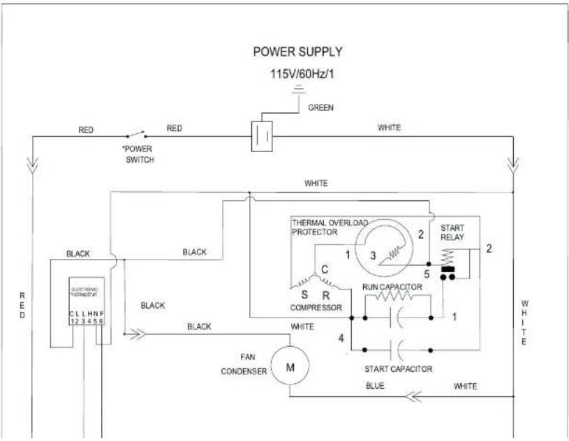
FOR THE SERVICE TECH - WIRING DIAGRAM FOR MT49 HINGED DOOR
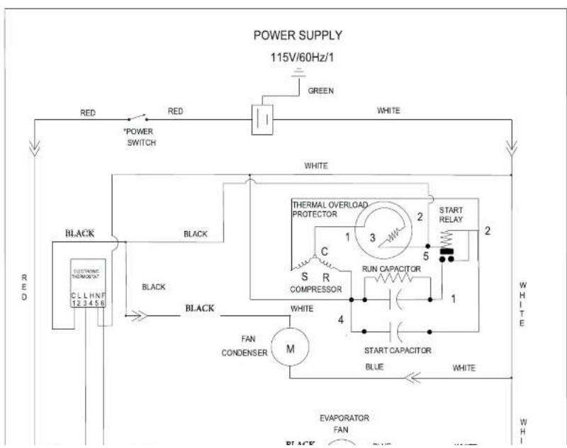
text_image
POWER SUPPLY 115V/60Hz/1 RED *POWER SWITCH GREEN WHITE WHITE BLACK BLACK THERMAL OVERLOAD PROTECTOR START RELAY 1 3 2 2 C R COMPRESSOR RUN CAPACITOR 5 1 BLACK BLACK FAN CONDENSER M 4 START CAPACITOR BLUE WHITE ELECTRONIC TEMPORATE CL H N F 12 3 4 5 6 RED WHITE W H I EVAPORATOR FAN BLACKUser Manual for MT Refrigerators and Freezers Beverage-Air
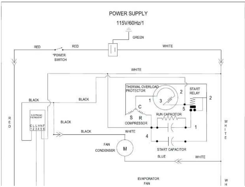
FOR THE SERVICE TECH - WIRING DIAGRAM FOR MT49 SLIDING DOOR
flowchart
graph TD
    A["POWER SUPPLY 115V/60Hz/1"] --> B["RED"]
    B --> C["POWER SWITCH"]
    C --> D["BLACK"]
    D --> E["CL L H N F 12.3-4.5.6"]
    E --> F["BLACK"]
    F --> G["FAN CONDENSER M"]
    G --> H["M"]
    H --> I["START CAPACITOR"]
    I --> J["RUN CAPACITOR"]
    J --> K["COMPRESSOR"]
    K --> L["THERMAL OVERLOAD PROTECTOR"]
    L --> M["START RELAY"]
    M --> N["2"]
    N --> O["1"]
    O --> P["3"]
    P --> Q["4"]
    Q --> R["5"]
    R --> S["2"]
    S --> T["WHITE"]
    U["WHITE"] --> V["WHIT E"]
    W["RED"] --> X["RED"]
    Y["WHITE"] --> Z["WHITE"]
User Manual for MT Refrigerators and Freezers Beverage-Air
FOR THE SERVICE TECH - WIRING DIAGRAM FOR MT53 HINGED DOOR

text_image
POWER SUPPLY 115V/60Hz/I GREEN RED +POWER SWITCH WHITE THermal OVERLOAD PROTECTOR 2 START RELAY 2 BLACK 1 3 C 5 R RUN CAPACITOR COMPRESSOR WHITE 4 START CAPACITOR WHITE FAN CONDENSER M BLUE WHITE +4 EVAPORATOR FANUser Manual for MT Refrigerators and Freezers Beverage-Air
FOR THE SERVICE TECH - WIRING DIAGRAM FOR MT53 SLIDING DOOR
text_image
POWER SUPPLY 115V/60Hz/1 RED *POWER SWITCH GREEN WHITE WHITE BLACK BLACK THERMAL OVERLOAD PROTECTOR START RELAY 1 3 2 C S R COMPRESSOR RUN CAPACITOR 1 4 FAN CONDENSER M START CAPACITOR BLUE WHITE EVAPORATOR FAN RED C L H N F 1 2 3 4 5 6 WHITE WH W HUser Manual for MT Refrigerators and Freezers Beverage-Air
FOR THE SERVICE TECH · WIRING DIAGRAM FOR MT72

text_image
SUPPLY VOLTAGE 115V/60Hz/1 YELLOW/GREEN OPTIONAL RED MAIN SWITCH RED OVERLOAD CUTOUT WHITE WHITE RED WHITE BLACK BEV BLACK TIMER WHITE BLACK THERMAL PROTECTOR BLACK COMPRESSOR START CAPACITOR STARTER RELAY S R C R YELLOW / GREEN M CONDENSER FAN WHITE WHITE RED BROWN 1 2 3 4 5 6 F C L L H N F DANFOSS CONTROL ETCIR RED THERMAL PROTECTOR BLACK COMPRESSOR START CAPACITOR STARTER RELAY S R C R YELLOW / GREEN M CONDENSER FAN WHITEUser Manual for MT Refrigerators and Freezers Beverage-Air
FOR THE SERVICE TECH - WIRING DIAGRAM FOR MTF53
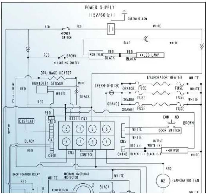
text_image
POWER SUPPLY 115V/60Hz/1 GREEN/YELLOW RED RED POWER SWITCH RED BROWN *LIGHTING SWITCH BRINER BLACK BLUE RED RED LED LAMP WHITE DRAIMAGE HEATER HUMIDITY SENSOR WHITE BLACK THERM-O-DISC ORANGE FUSE FUSE WHITE ORANGE FUSE FUSE WHITE ORANGE FUSE FUSE WHITE COM - NO BROWN DISPLAY CN10 CN7 8 7 6 5 CN5 WHITE Output RED (+) WHITE (+) CNI4B BLACK (-) **DRIVER WHITE BLACK CONTROL CN3 CONTROL CONN2 CN6B RED BLACK BRINER DOOR SWITCH BOOR HEATHER RELAY RED THermal Overload PROTECTOR WHITE M2 EVAPORATOR FAN COMPRESSOR 2 BLACKUser Manual for MT Refrigerators and Freezers Beverage-Air
LIMITED WARRANTY
WARRANTY (Warranty valid in USA and Canada)
THREE (3) YEAR PARTS AND LABOR WARRANTY:
Beverage-Air Corporation warrants to the original purchaser of Beverage-Air branded equipment, including all parts thereof, that such equipment is free from defects in material and workmanship, under normal use, proper maintenance, and service as indicated by Beverage-Air installation and operation instructions, for a period of three (3) years from the date of installation, or thirty-nine (39) Months from the date of shipment from the manufacturer, whichever is earlier.
ADDITIONAL FOUR (4) YEAR COMPRESSOR PART
WARRANTY': In addition to the warranty set forth above, Beverage-Air warrants the hermetically/semi-hermetically sealed compressor (part only) for an additional FOUR (4) years beyond the first three (3) years warranty period; not to exceed eighty-seven (87) months from the date of shipment from Beverage-Air, provided upon receipt of the compressor, manufacturer examination shows the sealed compressor to be defective. This extended warranty does not cover freight for the replacement compressor or freight for the return of the failed compressor.
* Units shipped after 03/01/2020. Previous warranty applies to units shipped prior.
EXCEPTIONS:
BEVERAGE-AIR
Also, this extended compressor-part only warranty does NOT apply to any electrical controls, condenser, evaporator, fan motors, overload switch, starting relay, capacitors, temperature control, filter/drier, accumulator, refrigeration tubing, wiring harness, labor charges, or supplies which are covered by the warranty above.
Normal wear type parts, such as light bulbs/lamps and gaskets are not covered by this warranty. For the purpose of this warranty, the original purchaser shall be deemed to mean the individual or company for who the product was originally installed.
Our obligation under this warranty shall be limited to repairing or replacing, including labor, any part of such product, which proves thus defective. Beverage-Air reserves the right to examine any product claimed to be defective.
The labor warranty shall be for self-contained units only and for standard straight time, which is defined as normal service rate time, for service performed during normal working hours. Any service requested outside of a servicer's normal working hours will be covered under this warranty at the normal rate and any additional overtime rate will be at the responsibility of the equipment purchaser.
Any part or accessory determined to be defective in the
User Manual for MT Refrigerators and Freezers Beverage-Air
LIMITED WARRANTY (CONTINUED)
With the exception of Blast Chillers product is designed for maintaining temperature and not bringing food to a desired temperature therefore cannot be held responsible for this function under warranty.
Units must be in a conditioned environment or warranty will be void.
Condensing coils must be cleaned at regular intervals. Failure to do so can cause compressor malfunction and will void warranty. Although cleaning requirements vary in accordance with operation of various products, Beverage-Air recommends a minimum monthly cleaning.
NO CLAIMS CAN BE MADE AGAINST THIS WARRANTY FOR SPOILAGE OF FOOD. PRODUCTS, LOSS OF SALES OR CONSEQUENTIAL DAMAGES.
THE FOREGOING WARRANTIES ARE EXPRESSLY GIVEN IN LIEU OF ALL OTHER WARRANTIES, EXPRESS, IMPLIED, OR STATUTORY, INCLUDING THE IMPLIED WARRANTIES OF MERCHANTABILITY AND FITNESS FOR A PARTICULAR PURPOSE, WHICH ARE HERBY DISCLAIMED, ALL OTHER OBLIGATIONS OR LIABILITIES ON OUR PART, AND WE NEITHER ASSUME, NOR AUTHORIZE ANY OTHER PERSON TO ASSUME FOR US, ANY OBLIGATION OR LIABILITY IN CONNECTION WITH THE SALE OF SAID REFRIGERATION UNITS OR ANY PARTS THERE OF.
This warranty shall not be assignable and shall be honored only in so far as the original purchaser. This warranty
IDENTIFIED ABOVE WHICH UNDER NORMAL USE AND SERVICE MALFUNCTION AS A RESULT OF DEFECTS IN MATERIAL OR WORKMANSHIP, SUBJECT TO THE APPLICABLE PROVISIONS AND LIMITATIONS STATED ABOVE.
Beverage-Air reserves the right to change the price and specifications of the equipment and/or material without notice. Prices are F.O.B. plant of manufacture.
CANCELLATION
Buyer may cancel it's order, reduce quantities, revise specifications, or extend schedules only by mutual agreement. As to reasonable and proper cancellation charges, it shall be taken into account expenses already incurred and commitment made by seller, and buyer shall indemnify seller against any loss.
FREIGHT CLASS
All Beverage-Air products ship under 150 freight classification.
CUSTOMER'S FREIGHT DAMAGE PROCEDURE
Before signing the carrier's freight bill, the customer should do the following:
Visible Damage:
- Inspect shipment for any damage. If you see
User Manual for MT Refrigerators and Freezers Beverage-Air
LIMITED WARRANTY (CONTINUED)
Concealed Damage:
- If the damage is concealed, notify the carrier within 48 hours by phone and in writing. Ask them to send their agent to complete an inspection report. Retain all cartons and merchandise for inspection. It is critical that the customer take the above actions.
3RD PARTY FREIGHT
3rd Part Freight shipments are FOB factory and not eligible for refusal at time of delivery. ALL 3RD PARTY SHIPMENTS ARE THE RESPONSIBILITY OF THE SHIPPER. Claims for damaged product are to be filed by the shipper and Beverage-Air will not be liable. This product is not eligible for return to our warehouse facility.
RETURN OF PRODUCT
EQUIPMENT - Prior Authorization must be granted by Beverage-Air before equipment can be returned for credit. Returns will only be authorized within 90 days of invoice date. Return Authorizations are valid for 30 days. Equipment approved for return is subject to a 25% restocking charge. Returned equipment must be shipped freight pre-paid, packed in original carton, and received in good condition.
PARTS - Prior Authorization must be granted by Beverage-Air before parts can be returned for credit. Returns will only be authorized within 30 days of invoice date. Return
User Manual for MT Refrigerators and Freezers Beverage-Air
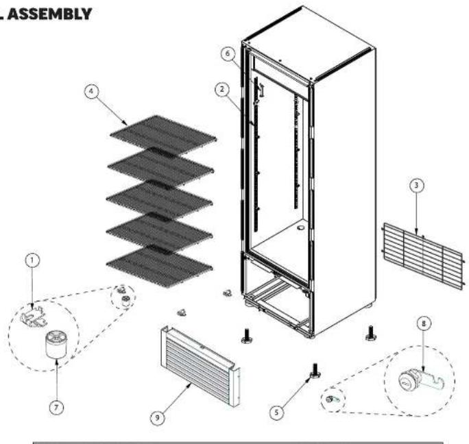
REPLACEMENT PARTS FOR MT06
GENERAL ASSEMBLY

text_image
1 2 3 4 5 6 7 8 9 10 11 12 13 14 15 16 17 18 Item Spare Part Cod 1 2091390| Item | Spare Port Code | Description |
| 1 | 2091390 | PILASTER |
| 2 | 2076344 | MOLD DEFLECTOR SUPPORT |
| 3 | 2089104 | DEFLECTOR MOLDING |
| 4 | 2091391 | HIGH IMP MOULDING |
| 5 | 2078388 | BUSHING |
| 6 | 2076486 | WIRE COVER |
| 7 | 2065032 | SWITCH |
| 8 | 2081664 | TEMPERATURE COUPLING |
User Manual for MT Refrigerators and Freezers Beverage-Air

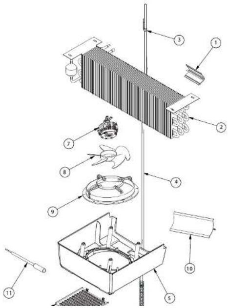
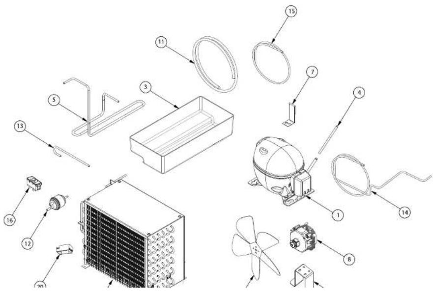
text_image
EVAPORATOR UNITUser Manual for MT Refrigerators and Freezers Beverage-Air
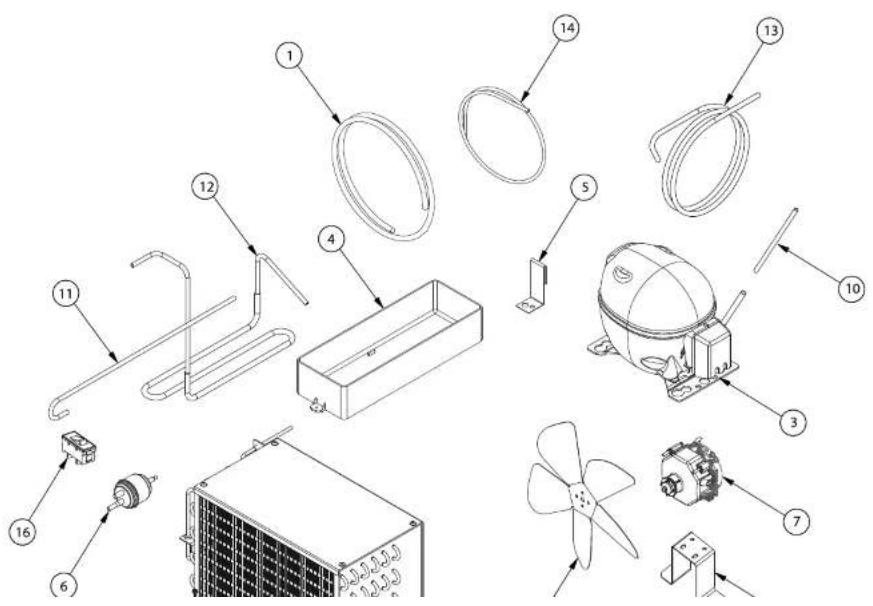
CONDENSER UNIT

text_image
1 2086070 C 3 4 5 6 7 8 9 10 11 12 13 14 15 1 2 3 4 5 6 7 8 9 10 11 12 13 14 15 Item Spare Part Code I 2086070 C#| Item | Spare Part Code | Description |
| 1 | 2086070 | COMPRESSOR BASE |
| 2 | 2073988 | COMPRESSOR |
User Manual for MT Refrigerators and Freezers Beverage-Air
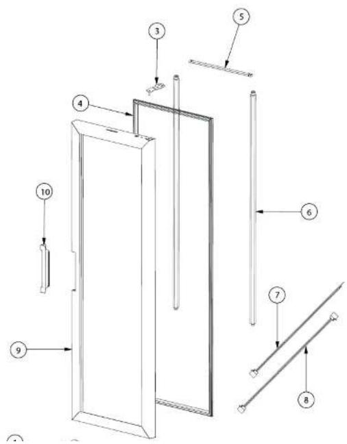
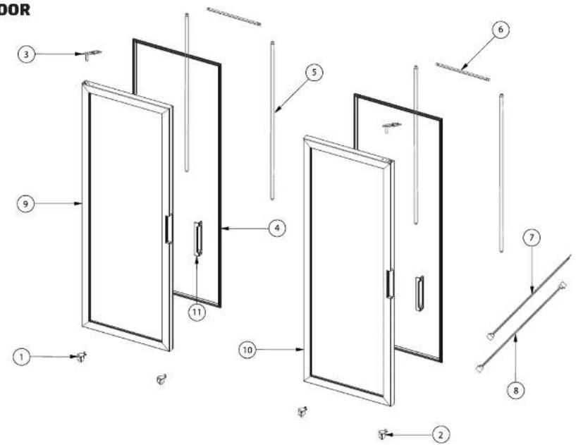
DOOR
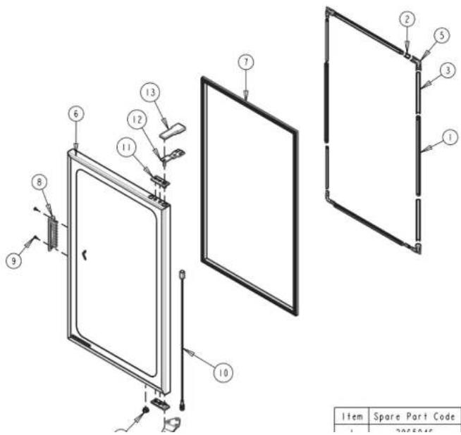
text_image
Item Spare Part Code 1 2025.04.16| Item | Spare Part Code | Description |
| 1 | 2055045 | LED MODULE |
User Manual for MT Refrigerators and Freezers Beverage-Air
REPLACEMENT PARTS FOR MT08
GENERAL ASSEMBLY
text_image
ASSEMBLY ① ② ③ ④ ⑤ ⑥ ⑦ ⑧ ⑨User Manual for MT Refrigerators and Freezers Beverage-Air
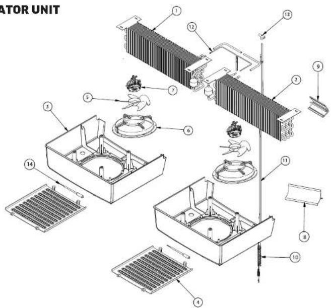
EVAPORATOR UNIT
text_image
Technical diagram of a mechanical assembly with numbered components for identificationUser Manual for MT Refrigerators and Freezers Beverage-Air
CONDENSER UNIT
text_image
Exploded view diagram of an air conditioning system with numbered components for identificationUser Manual for MT Refrigerators and Freezers Beverage-Air
CONDENSER UNIT CONT'D
| ITEM | SPARE PART CODE | DESCRIPTION |
| 1 | 2036380 | HOSE 18MM, 0.090M |
| 2 | 2050115 | CONDENSER |
| 3 | 2073988 | COMPRESSOR, EMC3130U |
| 4 | 2016580 | COND PAN |
User Manual for MT Refrigerators and Freezers Beverage-Air
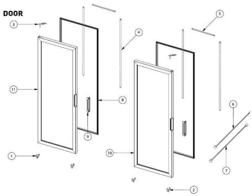
DOOR
text_image
Technical diagram of a door frame assembly with numbered components for identificationUser Manual for MT Refrigerators and Freezers Beverage-Air
REPLACEMENT PARTS FOR MT10
GENERAL ASSEMBLY
text_image
Exploded view diagram of an air conditioner unit with numbered components and assembly notesITEM PARE PART CODE
DESCRIPTION
User Manual for MT Refrigerators and Freezers Beverage-Air
EVAPORATOR UNIT

text_image
2nd Stator Skin 5 6 7 4 3 10 8 9User Manual for MT Refrigerators and Freezers Beverage-Air
CONDENSER UNIT

text_image
Exploded view diagram of a refrigerator with numbered parts for identification and assembly reference.User Manual for MT Refrigerators and Freezers Beverage-Air
CONDENSER UNIT CONT'D
| ITEM | SPARE PART CODE | DESCRIPTION |
| 1 | 2036380 | HOSE 18MM, 0.090M |
| 2 | 2065074 | CONDENSER |
| 3 | 2065310 | COMPRESSOR, EMC3130U |
| 4 | 2016580 | COND PAN |
| 5 | 2045818 | COND PAN SUPPORT |
User Manual for MT Refrigerators and Freezers Beverage-Air
DOOR
text_image
Technical diagram of a door frame assembly with numbered components and directional arrows indicating assembly steps.User Manual for MT Refrigerators and Freezers Beverage-Air
REPLACEMENT PARTS FOR MT12
GENERAL ASSEMBLY
text_image
AL ASSEMBLY ① ② ③ ④ ⑤ ⑥ ⑦ ⑧ ⑨User Manual for MT Refrigerators and Freezers Beverage-Air
EVAPORATOR UNIT
text_image
DRATOR UNIT 7 8 10 6 5 10 3 9User Manual for MT Refrigerators and Freezers Beverage-Air
CONDENSER UNIT

text_image
Exploded view diagram of a refrigerator and air conditioning unit with numbered parts for identification.User Manual for MT Refrigerators and Freezers Beverage-Air
CONDENSER UNIT CONT'D
| ITEM | SPARE PART CODE | DESCRIPTION |
| 1 | 2036380 | HOSE 18MM, 0.090M |
| 2 | 2065074 | CONDENSER |
| 3 | 2063501 | COMPRESSOR, EMC3130U |
| 4 | 2016580 | COND PAN |
| 5 | 2045838 | COND PAN SUPPORT |
User Manual for MT Refrigerators and Freezers Beverage-Air
DOOR
text_image
Technical diagram of a door frame assembly with numbered components for identification and assembly reference.User Manual for MT Refrigerators and Freezers Beverage-Air
REPLACEMENT PARTS FOR MT23
GENERAL ASSEMBLY
text_image
ASSEMBLY ① ② ③ ④ ⑤ ⑥ ⑦ ⑧ ⑨User Manual for MT Refrigerators and Freezers Beverage-Air
EVAPORATOR UNIT
text_image
UNIT 1 2 3 4 5 6 7 8 9 10 11User Manual for MT Refrigerators and Freezers Beverage-Air
CONDENSER UNIT

text_image
Exploded view diagram of an air conditioning unit with numbered components for identificationUser Manual for MT Refrigerators and Freezers Beverage-Air
CONDENSER UNIT CONT'D
| ITEM | SPARE PART CODE | DESCRIPTION |
| 1 | 2056380 | HOSE 18MM, 0.090M |
| 2 | 2061514 | CONDENSER |
| 3 | 2072402 | COMPRESSOR, EMC3130U |
| 4 | 2017314 | COND PAN |
User Manual for MT Refrigerators and Freezers Beverage-Air
DOOR
text_image
Technical diagram of a door frame assembly with numbered components for identification and assembly reference.User Manual for MT Refrigerators and Freezers Beverage-Air
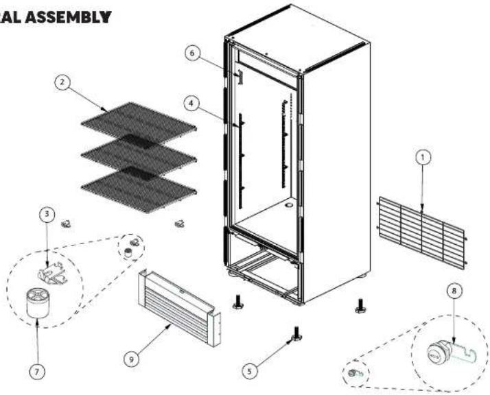
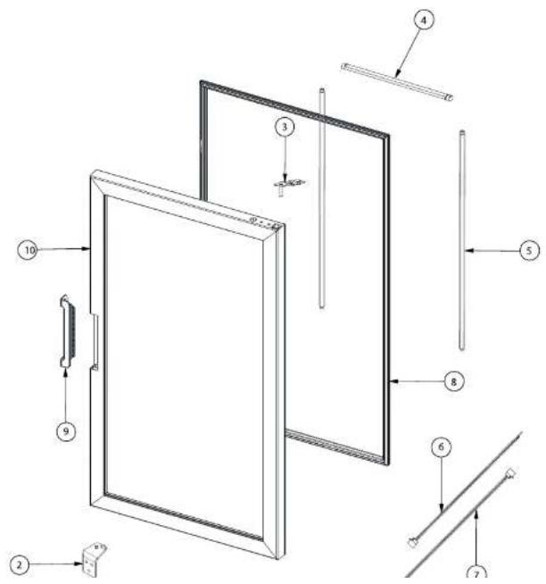
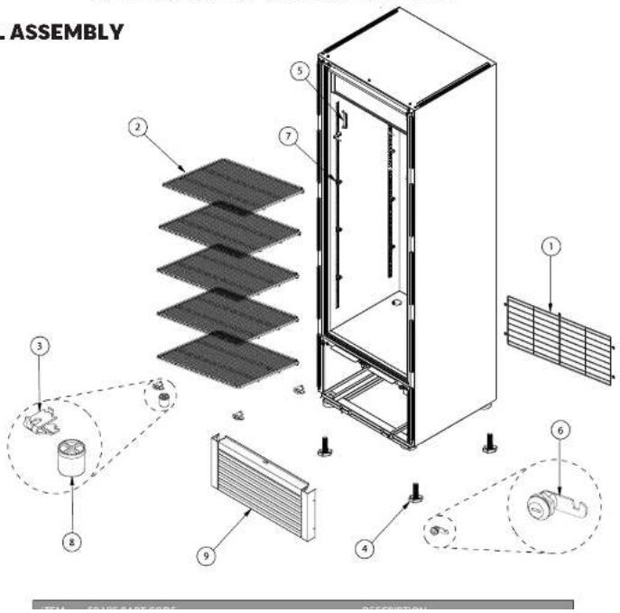
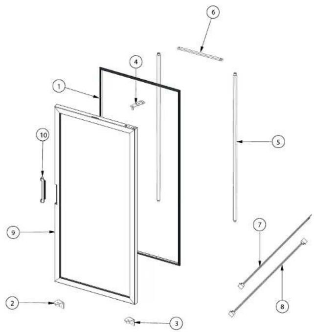
REPLACEMENT PARTS FOR MT49 HINGED DOOR
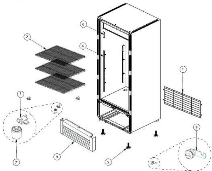
GENERAL ASSEMBLY ^3

text_image
TERAL ASSEMBLY ③ ⑤ ① ② ④ ⑦ ⑨ ⑥ ⑧User Manual for MT Refrigerators and Freezers Beverage-Air
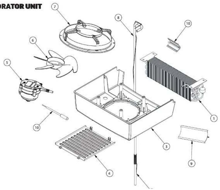
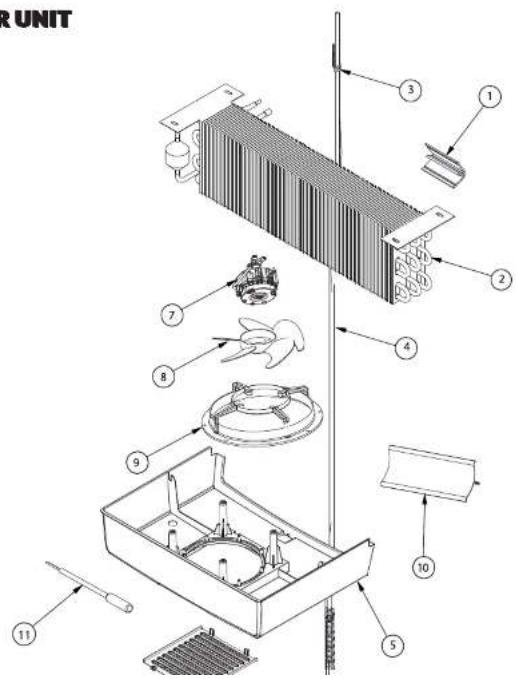
EVAPORATOR UNIT

text_image
PORATOR UNITUser Manual for MT Refrigerators and Freezers Beverage-Air
CONDENSER UNIT

text_image
Exploded view diagram of a refrigerator with numbered parts for identification and assembly reference.User Manual for MT Refrigerators and Freezers Beverage-Air
CONDENSER UNIT CONT'D
| ITEM | SPARE PART CODE | DESCRIPTION |
| 1 | COMPRESSOR, EMC3134U | |
| 2 | 2056133 | CONDENSER |
| 3 | 2024707 | COND PAN |
| 4 | 2063514 | CHARGE PIPE |
| 5 | DISCHARGE PIPE |
User Manual for MT Refrigerators and Freezers Beverage-Air
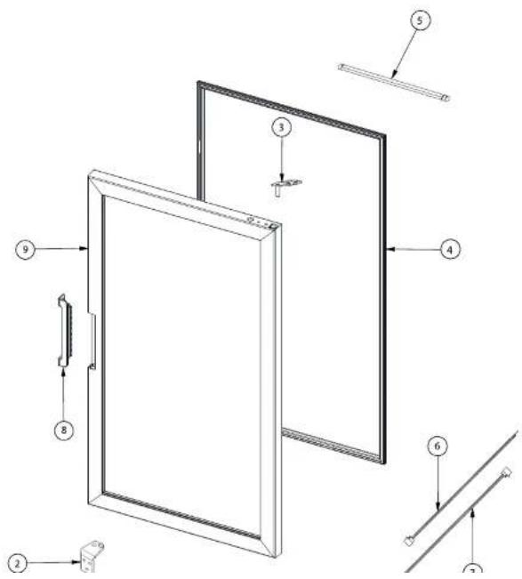
DOOR
text_image
DOOR ③ ⑤ ⑥ ⑦ ⑧ ⑨ ⑪ ⑩ ① ②User Manual for MT Refrigerators and Freezers Beverage-Air
REPLACEMENT PARTS FOR MT49 SLIDING DOOR
GENERAL ASSEMBLY

text_image
Technical diagram of a solar panel installation with numbered components and labeled partsITEM SPARE PART CODE
DESCRIPTION
User Manual for MT Refrigerators and Freezers Beverage-Air
EVAPORATOR UNIT

text_image
Exploded view diagram of a refrigerator assembly with numbered components for identificationUser Manual for MT Refrigerators and Freezers Beverage-Air
CONDENSER UNIT
text_image
Exploded view diagram of an air conditioning unit with numbered parts for identificationUser Manual for MT Refrigerators and Freezers Beverage-Air
CONDENSER UNIT CONT'D
| ITEM | SPARE PART CODE | DESCRIPTION |
| 1 | 2068683 | COMPRESSOR, NLE8.8CN |
| 2 | 2056133 | CONDENSER |
| 3 | 2024707 | COND PAN |
| 4 | 2063514 | CHARGE PIPE |
| 5 | 2073253 | DISCHARGE PIPE |
User Manual for MT Refrigerators and Freezers Beverage-Air
DOOR

text_image
Technical diagram showing assembly steps of a panel with numbered components and directional arrows indicating assembly direction.User Manual for MT Refrigerators and Freezers Beverage-Air
REPLACEMENT PARTS FOR MT53 HINGED DOOR
GENERAL ASSEMBLY

text_image
Technical diagram of a solar panel installation system with numbered components and component layoutsUser Manual for MT Refrigerators and Freezers Beverage-Air
EVAPORATOR UNIT

text_image
Exploded view diagram of a refrigerator assembly with numbered components for identificationUser Manual for MT Refrigerators and Freezers Beverage-Air
CONDENSER UNIT

text_image
Exploded view diagram of an air conditioning unit with numbered parts for identificationUser Manual for MT Refrigerators and Freezers Beverage-Air
CONDENSER UNIT CONT'D
| ITEM | SPARE PART CODE | DESCRIPTION |
| 1 | 2068683 | COMPRESSOR, EMC3140U |
| 2 | 2056133 | CONDENSER |
| 3 | 2024707 | COND PAN |
| 4 | 2063514 | CHARGE PIPE |
| 5 | 2073249 | DISCHARGE PIPE |
| 6 | 2073247 | HEAT EXCHANGER |
| 7 | 2068684 | MOTOR COND SUPPORT |
| 8 | 2073254 | COND PAN SUPPORT |
| 9 | 2065335 | COND FAN MOTOR, 16W 1800RPM |
| 10 | 2061515 | COND FAN BLADE, 8 3/4" ∅25" |
| 11 | 2061516 | HOSE, 5/8" 1.20M |
| 12 | 2055229 | FILTER |
| 13 | 2072429 | VACCUM PIPE |
| 14 | 2065163 | POWER CORD |
| 15 | 2065320 | HOSE 18MM, 0.090M |
| 16 | 2016558 | ROCKER SWITCH |
| 17 | 2048141 | LED DRIVER |
| 18 | 2068369 | CONTROL HARNESS |
User Manual for MT Refrigerators and Freezers Beverage-Air
text_image
DOOR ③ ④ ⑤ ⑥ ⑦ ⑧ ⑨ ⑩ ⑪ ⑫ ⑬ ⑭ ⑮User Manual for MT Refrigerators and Freezers Beverage-Air
REPLACEMENT PARTS FOR MT53 SLIDING DOOR

text_image
GENERAL ASSEMBLY ② ⑤ ⑧ ③ ⑥ ⑨ ④ ⑦User Manual for MT Refrigerators and Freezers Beverage-Air
EVAPORATOR UNIT
text_image
ATOR UNITUser Manual for MT Refrigerators and Freezers Beverage-Air
CONDENSER UNIT

text_image
Exploded view diagram of an air conditioning system with numbered components for identificationUser Manual for MT Refrigerators and Freezers Beverage-Air
CONDENSER UNIT CONT'D
| ITEM | SPARE PART CODE | DESCRIPTION |
| 1 | 2068683 | COMPRESSOR, EMC3140U |
| 2 | 2056133 | CONDENSER |
| 3 | 2024707 | COND PAN |
| 4 | 2063514 | CHARGE PIPE |
| 5 | DISCHARGE PIPE |
User Manual for MT Refrigerators and Freezers Beverage-Air
DOOR
text_image
Technical diagram showing five labeled components of a panel assembly or installation, with numbered annotations pointing to different parts.User Manual for MT Refrigerators and Freezers Beverage-Air
REPLACEMENT PARTS FOR MTF23
GENERAL ASSEMBLY
text_image
Technical diagram of a modular device with numbered components and labeled parts, likely for assembly or manufacturing documentation.User Manual for MT Refrigerators and Freezers Beverage-Air
GENERAL ASSEMBLY CONT'D
| Item | Spare Part Code | Description |
| 1 | 2055505 | ANTI - VACUUM VALVE |
| 2 | 2077027 | PILASTER |
| 3 | 2089494 | TUBE COVER |
| 4 | 2089506 | HIGH IMP MOULDING |
| 5 | 2080131 | DEFLECTOR MOLDING |
| 6 | 2076344 | MOLD DEFLECTOR SUPPORT |
| 7 | 2076341 | MAGNETIC SWITCH |
| 8 | 2077330 | INTERLOCK, MAG SWITCH |
| 9 | 2089510 | CLIP |
| 10 | 2024708 | SWITCH SUPPORT |
| 11 | 2076347 | SWITCH |
| 12 | 2076349 | SWITCH SUPPORT |
| 13 | 2089496 | TEMPERATURE CONTROL |
| 14 | 2076370 | CONTROL BOX |
| 15 | 2089531 | LED DRIVER |
| 16 | 2089533 | RELAY |
| 17 | 2089516 | CONTROL BOX |
| 18 | 2078624 | GROMMET |
| 19 | 2077048 | REMOTE DISPLAY |
| 20 | 2084846 | DLPAY SUPPORT |
| 21 | 2077061 | DPLAY BASE |
| 22 | 2077060 | PANEL COVER |
| 23 | 2089515 | DPLAY LABEL |
| 24 | 2076368 | DRIVER 24W |
| 25 | 2089523 | POWER CORD |
| 26 | 2077142 | BACK GRILL |
User Manual for MT Refrigerators and Freezers Beverage-Air
EVAPORATOR UNIT
| Item | Spare Part Code | Description |
| 1 | 2089526 | HARNESS |
| 2 | 2089517 | EVAPORATOR |
| 3 | 2089540 | EVAP HEATER |
| 4 | 2089490 | RETURN PIPE |
| 5 | 2087781 | CAPILLARY TUBE, 0.031"X150" |
| 6 | 2089491 | RETURN PIPE |
| 7 | 2065308 | ACUMMULATOR |
| 8 | 2078824 | BIMETAL DISC |
| 9 | 2089528 | HARNESS |
| 10 | 2089492 | EVAP HOUSING |
| 11 | 2068676 | FAN BLADE GRILL |
| 12 | 2089519 | EVAP DRAIN PAN |
| 13 | 2089534 | LEFT AIR DEVIATOR |
| 14 | 2089539 | RIGHT AIR DEVIATOR |
| 15 | 2078624 | GROMMET |
| 16 | 2089542 | DRAIN HEATER |
| 17 | 2065102 | EVAP FAN BLADE |
| 18 | 2021792 | MOTOR EVAP SUPPORT |
| 19 | 2022630 | EVAP FAN MOTOR |
text_image
Technical diagram of a mechanical assembly with numbered components and directional arrows indicating assembly steps.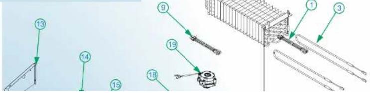
text_image
Technical diagram showing numbered components of a mechanical assembly with labeled parts 1 through 19.User Manual for MT Refrigerators and Freezers Beverage-Air
CONDENSER UNIT
| Item | Spare Part Code | Description |
| 1 | 2065116 | FILTER DRIER |
| 2 | 2076400 | VACCUM PIPE |
| 3 | 2077036 | COMPRESSOR BASE |
| 4 | 2089511 | COMPRESSOR |
| 5 | 2089520 | CONDENSER |
| 6 | 2045838 | COND PAN SUPPORT |
| 7 | 2065072 | CONDENSATE PAN |
| 8 | 2077039 | CHARGE PIPE |
| 9 | 2089488 | DISCHARGE PIPE |
| 10 | 2089493 | SUCTION LINE |
| 11 | 2089507 | PIPE |
| 12 | 2083587 | PIPE SUPPORT |
| 13 | 2077074 | MOTOR STAND |
| 14 | 2016551 | MOTOR COND SUPPORT |
| 15 | 2022630 | COND FAN MOTOR |
| 16 | 2017317 | COND FAN BLADE |
| 17 | 2077326 | PIPE INSULATION |
| 18 | 2089838 | ACC COMPRESSOR KIT |
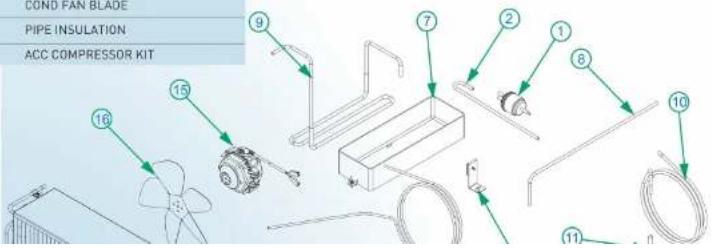
text_image
COND FAN BLADE PIPE INSULATION ACC COMPRESSOR KIT 9 7 2 1 8 10 15 16User Manual for MT Refrigerators and Freezers Beverage-Air
text_image
DOOR 1 2 3 4 5 6 7 8 9 10 11 12 Item Spare Part Code DeItem
Spare Part Code
Description
User Manual for MT Refrigerators and Freezers Beverage-Air
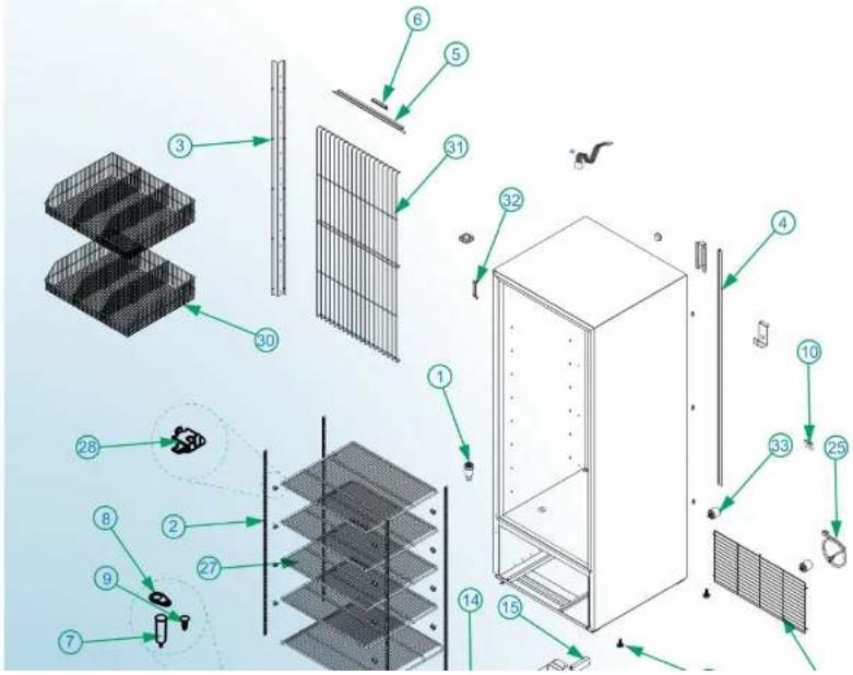
REPLACEMENT PARTS FOR MTF53
GENERAL ASSEMBLY

text_image
Exploded view diagram of a server rack system with numbered components for identificationUser Manual for MT Refrigerators and Freezers Beverage-Air
GENERAL ASSEMBLY CONT'D
| ITEM | SPARE PART | DESCRIPTION |
| 1 | 2055505 | ANTI-VACUUM VALVE |
| 2 | 2078071 | GASKET ANTI-VACUUM VALVE |
| 3 | 2108873 | TUBE COVER |
| 4 | 2080114 | PILASTER |
| 5 | 2108674 | WIRE COVER |
| 6 | 2103930 | WIRE COVER SUPPORT |
| 7 | 2089506 | HIGH IMP MOULDING |
| 8 | 2076344 | MOLD DEFLECTOR SUPPORT |
| 9 | 2091398 | DEFLECTOR MOLDING |
| 10 | 2103916 | FRONTAL POLE |
| 11 | 2085665 | TUBE COVER |
| 12 | 2089533 | RELAY |
| 13 | 2024708 | MAGNETIC SUPPORT SWITCH |
| 14 | 2076341 | MAGNETIC SWITCH |
| 15 | 2077330 | INTERLOCK, MAG SWITCH |
| 16 | 2089510 | CLIP P/SWITCH |
| 17 | 2065052 | SWITCH |
| 18 | 2089531 | LED DRIVER |
| 19 | 2103919 | TEMPERATURE CONTROL |
| 20 | 2076370 | CONTROL BOX |
| 21 | 2077048 | DISPLAY MOTHERBOARD |
| 22 | 2077061 | DPLAY BASE |
| 23 | 2077060 | PANEL COVER |
| 24 | 2108493 | DPLAY LABEL |
| 25 | 2076368 | DRIVER 24W |
| 26 | 2047063 | BACK GRILL |
| 27 | 2065163 | POWER CORD |
| 28 | 2103929 | SHELF |
| 29 | 2065346 | CLIP F/PILASTER |
User Manual for MT Refrigerators and Freezers Beverage-Air
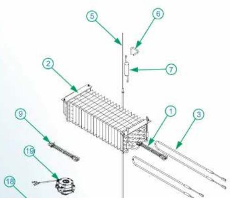
EVAPORATOR UNIT

text_image
ITEM SPARE PART DESCRIPTION 1 2091441 EVAPORATOR 2 2103920 RETURN PIPE 3 2089491 RETURN PIPE 4 206020 RETURN PIPE 5 206020 RETURN PIPE 6 206020 RETURN PIPE 7 1 2 3 4 5 6 7 8 9 10 11 12 13 14 15 16 17 18 19 20| ITEM | SPARE PART | DESCRIPTION |
| 1 | 2091441 | EVAPORATOR |
| 2 | 2103920 | RETURN PIPE |
| 3 | 2089491 | RETURN PIPE |
User Manual for MT Refrigerators and Freezers Beverage-Air
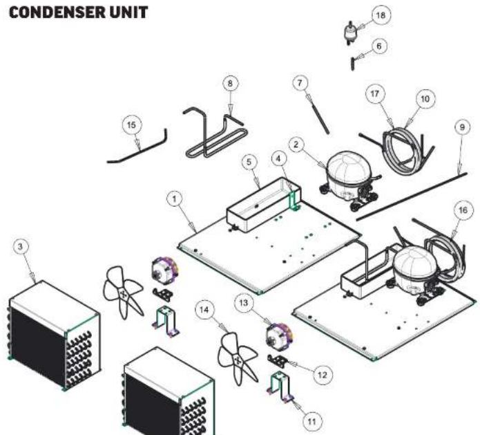
text_image
CONDENSER UNIT| ITEM | SPARE PART | DESCRIPTION |
| 1 | 2076542 | COMPRESSOR BASE |
User Manual for MT Refrigerators and Freezers Beverage-Air
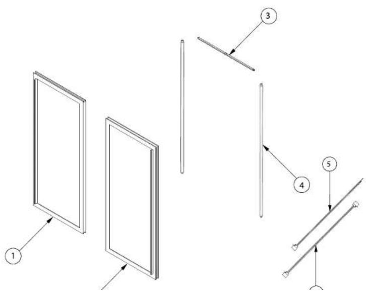
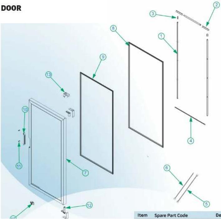
DOOR
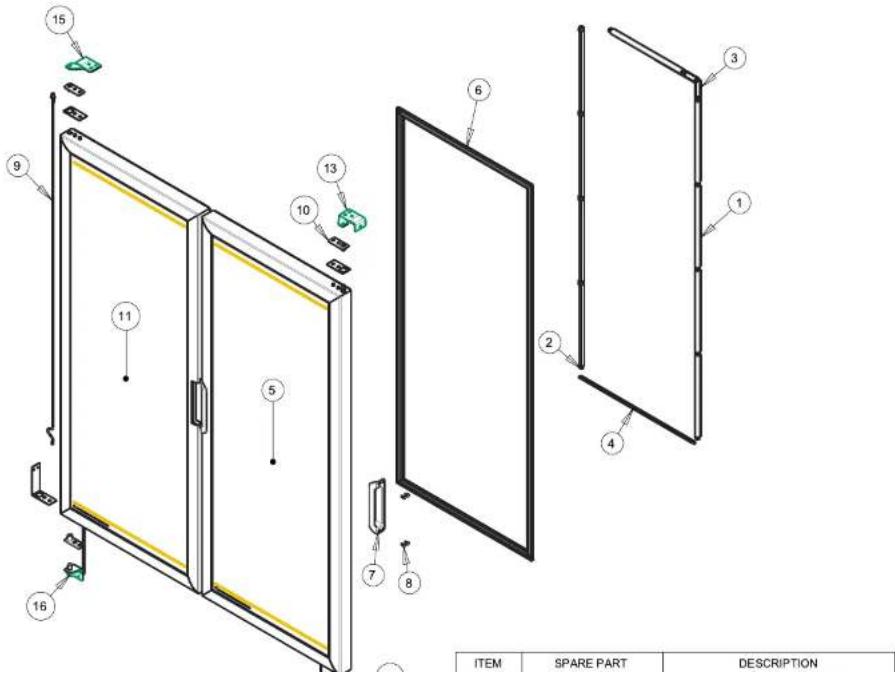
text_image
15 9 11 5 16 13 10 6 2 3 1 4 7 8 ITEM SPARE PART DESCRIPTIONUser Manual for MT Refrigerators and Freezers Beverage-Air
Warranty Registration
Register your product online at beverage-air.com/parts-service or fill out and mail the form below.
Cabinet Model Number:
Date Of Installation: