DH2589TBB - Security Camera FLIR - Free user manual and instructions
Find the device manual for free DH2589TBB FLIR in PDF.

User questions about DH2589TBB FLIR
0 question about this device. Answer the ones you know or ask your own.
Ask a new question about this device
Download the instructions for your Security Camera in PDF format for free! Find your manual DH2589TBB - FLIR and take your electronic device back in hand. On this page are published all the documents necessary for the use of your device. DH2589TBB by FLIR.
USER MANUAL DH2589TBB FLIR
text_image
DIGIMERGE | Right for BusinessInstruction Manual
English Version 3.0
natural_image
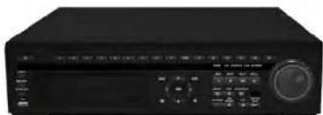
Front view of a black electronic device with control panel and rotary knob (no visible text or symbols)DH250 SERIES
Digital Video Surveillance Recorder
8/16 H.264 / CMS-DH PC/Mac 3G Mobile 480/480 D1
Thank you for purchasing this product. Digimerge is committed to providing our customers with a high quality, reliable security solution.
This manual refers to the following models:
For more information on this product, firmware updates, and accessory products, please visit us at:
www.digimerge.com

CAUTION
RISK OF ELECTRIC SHOCK DO NOT OPEN

CAUTION: TO REDUCE THE RISK OF ELECTRIC SHOCK DO NOT REMOVE COVER. NO USER SERVICABLE PARTS INSIDE.
REFER SERVICING TO QUALIFIED SERVICE PERSONNEL.

The lightning flash with arrowhead symbol, within an equilateral
Important Safeguards
In addition to the careful attention devoted to quality standards in the manufacturing process of your video product, safety is a major factor in the design of every instrument. However, safety is your responsibility too. This sheet lists important information that will help to assure your enjoyment and proper use of the video product and accessory equipment. Please read them carefully before operating and using your video product.
Installation
- Read and Follow Instructions - All the safety and operating instructions should be read before the video product is operated. Follow all operating instructions.
- Retain Instructions - The safety and operating instructions should be retained for future reference.
- Heed Warnings - Comply with all warnings on the video product and in the operating instructions.
- Polarization - Do not defeat the safety purpose of the polarized or grounding-type plug. A polarized plug has two blades with one wider than the other. A grounding type plug has two blades and a third grounding prong. The wide blade or the third prong are provided for your safety. If the provided plug does not fit into your outlet, consult an electrician for replacement of the obsolete outlet.
-
Power Sources - This video product should be operated only from the type of power source indicated on the marking label. If you are not sure of the type of power supply to your location, consult your video dealer or local power company. For video
-
Ventilation - Slots and openings in the case are provided for ventilation to ensure reliable operation of the video product and to protect it from overheating. These openings must not be blocked or covered. The openings should never be blocked by placing the video equipment on a bed, sofa, rug, or other similar surface. This video product should never be placed near or over a radiator or heat register. This video product should not be placed in a built-in installation such as a bookcase or rack unless proper ventilation is provided or the video product manufacturer's instructions have been followed.
- Attachments - Do not use attachments unless recommended by the video product manufacturer as they may cause a hazard.
- Camera Extension Cables - Check the rating of your extension cable(s) to verify compliance with your local authority regulations prior to installation.
- Water and Moisture - Do not use this video product near water. For example, near a bath tub, wash bowl, kitchen sink or laundry tub, in a wet basement, near a swimming pool and the like. Caution: Maintain electrical safety. Powerline operated equipment or accessories connected to this unit should bear the Ull listing mark of CSA
Service
- Servicing - Do not attempt to service this video equipment yourself as opening or removing covers may expose you to dangerous voltage or other hazards. Refer all servicing to qualified service personnel.
-
Conditions Requiring Service - Unplug this video product from the wall outlet and refer servicing to qualified service personnel under the following conditions:
-
When the power supply cord or plug is damaged.
- If liquid has been spilled or objects have fallen into the video product.
- If the video product has been exposed to rain or water.
- If the video product does not operate normally by following the operating instructions. Adjust only those controls that are covered by the operating instructions. Improper adjustment of other controls may result in damage and will often require extensive work by a qualified technician to restore the video product to its normal operation.
- If the video product has been dropped or the cabinet has been damaged.
-
When the video product exhibits a distinct change in performance. This indicates a need for service.
-
Replacement Parts - When replacement parts are required, have the service technician verify that the replacements used have the same safety characteristics as the original parts. Use of replacements specified by the video product manufacturer can prevent fire, electric shock or other hazards.
Use
- Cleaning - Unplug the video product from the wall outlet before cleaning. Do not use liquid cleaners or aerosol cleaners. Use a damp cloth for cleaning.
- Product and Cart Combination - Video and cart combination should be moved with care. Quick stops, excessive force, and uneven surfaces may cause the video product and car combination to overturn.
- Object and Liquid Entry - Never push objects for any kind into this video product through openings as they may touch dangerous voltage points or "short-out" parts that could result in a fire or electric shock. Never spill liquid of any kind on the video product.
-
Lightning - For added protection for this video product during a lightning storm, or when it is left unattended and unused for long periods of time, unplug it from the wall outlet and disconnect the antenna or cable system. This will prevent damage to the video product due to lightning and power line surges.
-
C-10-06: 12
General Precautions
- All warnings and instructions in this manual should be followed.
- Remove the plug from the outlet before cleaning. Do not use liquid aerosol detergents. Use a water dampened cloth for cleaning.
- Do not use this unit in humid or wet places.
- Keep enough space around the unit for ventilation. Slots and openings in the storage cabinet should not be blocked.
- During lightning storms, or when the unit is not used for a long time, disconnect the power supply, antenna, and cables to protect the unit from electrical surge.
FCC CLASS A NOTICE
NOTE
This equipment has been tested and found to comply with the limits for a Class A digital device pursuant to Part 15 of the FCC Rules. These limits are designed to provide reasonable protection against harmful interference when the equipment is operated in a commercial environment. This equipment generates, uses, and can radiate radio frequency energy and, if not installed and used in accordance with the manufacturer's instruction manual, may cause harmful interference with radio communications. Operation of this equipment in a residential area is likely to cause harmful interference, in which case you will be required to correct the interference at your own expense.
This equipment has been certified and found to comply with the limits regulated by FCC, EMC, and LVD. Therefore, it is designated to provide reasonable protection against interference and will not cause interference with other appliance usage.
DH230 Features

text_image
RGB RGB BRINJ S120% GPIO L120% GND Digital Power Control Digital Power Control Digital Power Control Digital Power Control Digital Power Control Digital Power Control Digital Power Control Digital Power Control Digital Power Control Digital Power Control Digital Power Control Digital Power Control Digital Power Control Digital Power Control Digital Power Control Digital Power Control Digital Power Control Digital Water• Real Time Recording: 120fps @ D1, 240fps @ 2CIF, 480fps @ CIF
• Event Log Search, Preview Search, Motion Area
- Search, Go To Search
• SMART network transfer
• HDMI, VGA, Spot, Looping Outputs
- Disk Mirroring Function
- Advanced user configuration
• Security Certified Hard Disk with up to 6TB of storage
- Hardware watch-dog/power Failure recovery: auto-reboot while maintaining settings and data
• DVR temperature alert, auto power-off
• S.M.A.R.T. HDD
• PC/Mac Compatible
• 3G Smartphone (BlackBerry, iPhone, Android)
- Tablet Compatible (iPad, Android, Windows)
• CMS-DH application supports up to 300 DVRs,
• 64 ch/screen, E-Map, full control, 8 screen display
DH250 Features
natural_image
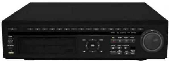
Front view of a black electronic device with control panel and rotary knob (no visible text or symbols)• Real Time Recording (480fps @D1, 720 x480)
• Event log Search, Preview Search, Motion Area Search, Go To Search
• HDMI, VGA, Spot, Looping Outputs
- Disk Mirroring Function
• Advanced User Configuration
• Security certified hard disk with up to 8TB internal storage
• Hardware Watch-Dog/Power Failure Recovery: Auto
- Reboot while Maintaining Previous Settings & Data
- Alarm Notification [MAX 5 users]: e-mail alert
• DVR Temperature alert: Auto Power-Off
• S.M.A.R.T HDD
• PC/Mac Compatible
• 3G Smartphone (BlackBerry, iPhone, Android)
- Tablet Compatible liPad, Android, Windows
CMS-DH application supports up to 300 DVRs, 64 ch/ screen, E-Map, full control, 8 screen display
TABLE OF CONTENTS
Getting Started....1
Basic Setup 2
- Connect the cameras 2
- Connect a monitor 2
- Connect the mouse 2
- Connect the Ethernet cable 2
- Connect the power cable 2
Touch Panel Tips and Tricks (DH230 only) 12
Using the System 13
Password 13
On-Screen Display 14
Using the Virtual Remote 16
Playback 17
Using the Virtual Keyboard 17
Event Record Search 26
Event Preview Search 27
Motion Area Search 28
External Search 29
Event Source Search 29
Setting up Sequencing 30
Sequence mode & Shift mode 30
Event View 31
Configuring the EVENT tab 32
Connecting a SPOT OUT / CAMERA OUT monitor (DH230/250) 32
Setting up Motion Recording 33
Triggering secondary cameras in Motion recording 36
Triggering cameras to record during Video Loss 37
Using the Main Menu 38
DISPLAY 39
GENERAL 39
SWITCH / EVENT 39
CAMERA 40
RECORD 41
GENERAL 41
MODE 41
DAY 42
DAY EVENT 42
NIGHT 43
NIGHT EVENT 44
SCHEDULE 45
CHART 45
HOLIDAY 45
DISK 47
DISK MANAGER 47
Recording Disk 48
Backing up to a USB Device or CD/DVD Burner 58
Backing up to an FTP Server 59
Viewing Backup Video 60
Using MCD Player 61
CMS-DH Central Management Software 63
System Requirements 63
Prerequisites 63
Installing CMS-DH 64
Starting CMS-DH 65
Adding a Virtual DVR 70
Creating New Group Folders & Sub folders 72
Configuring General System Settings 73
Adding Users 74
Recording Video to the hard drive 75
Playing back recorded video 76
Remote Search 77
Video Playback Controls 78
Local Search 78
Saving Video Files 79
Converting video files to AVI 80
Schedule Recording 81
Schedule Backup to Local Hard Drive 81
Configure Backup to FTP Server 83
Taking Screen Captures 84
Viewing File Download Status 85
Changing viewing modes 85
Sequencing 86
E-Map 87
E-Map Setup 88
Setting Video pop-up notifications 100
Configuring other Post Action Events 102
POS Data Search 102
Running CMS-DH on multiple monitors 103
iSMS Client (Remote Viewing on the Mac).... 104
System Requirements 104
Prerequisites 104
Installation Steps 104
Using the iSMS Client 105
iSMS Interface 106
Configuring OSD Settings 108
Searching for video remotely 108
Searching for video locally 111
Configuring PTZ settings 112
Configuring PTZ Protocols in the iSMS Client 114
Configuring the iSMS Client 115
iPhone: Digi iMobile Touch App.... 116
Compatible Devices 116
Prerequisites 117
Installation Steps 117
Starting Digi iMobile Touch 117
Configuring Digi iMobile Touch Lite/Pro 118
Connecting to your DVR 119
Digi iMobile Touch Lite Interface 119
Digi iMobile Touch Pro Interface 120
About the Search and Control menus 120
Changing Viewing Modes 121
Rotating the Screen 121
Toggling the On Screen Display (OSD) 122
Installing the BDVRViewer App on your Blackberry 130
Prerequisites 130
Step 1 of 4: Download the BDVRViewer Application 130
Step 2 of 4: Clear your browser cache 131
Step 3 of 4: Enable APN (Access Point Name) 132
Step 4 of 4: Log in to BDVRViewer 133
Viewing Tips 133
Appendix A: System Specifications 134
DH230 Specs 134
Appendix B: Setting up Remote Viewing 138
What Do I Need? 138
How Do I Find My IP and MAC addresses? 139
Finding Your External IP Address 139
How Do I Enable Port Forwarding? 140
Appendix C: Digimerge Auto Port Forward Wizard.... 141
Installation 141
Obtaining Your Router Model Number and Version 142
Example 142
Configuration 143
Initial Startup: Select language 143
Step 1: Populate the router database .... 143
Step 2: Enter your router settings ....144
Step 3: Update the router settings 145
Step 4: Test your connection ....145
Configuring multiple routers 145
Scenario A: Router/Modem combination + Router 146
Scearnio B: Multiple Routers 146
Example 147
Appendix J: Replacing the Hard Drive 165
Playing AVI Files 177
Appendix L: Remote Viewing using Internet Explorer.... 178
Appendix M: DH230/250 Series Touch Screen Monitor Setup ..... 180
Step 1 of 3: Connect the Cables ..... 180
Step 2 of 3: Power on the Monitor 181
Step 3 of 3: Test the Touch Screen Functions 181
Troubleshooting 182
Troubleshooting (cont'd.) 183
Remote Connectivity Trouble Shooting 184
GETTING STARTED
The system comes with the following components:
DH230 DVR*
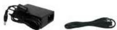
POWER SUPPLY
*Verify with the system package to confirm your system type. This package includes ONE [1] DVR

POWER CORD

9-PIN TO RCA AUDIO CABLE
(Note: 16-channel models include two 9-PIN to RCA Audio Cables)
BASIC SETUP
1. Connect the cameras
a. Connect BNC cameras to the BNC ports on the rear panel.
2. Connect a monitor
If you are using a touch screen monitor (not included), connect a USB cable (not included) from a USB port on the front or rear panel of the system to the monitor.
a. Connect a VGA cable (not included) from the VGA OUT port on the rear panel to the VGA port on your monitor, OR
b. Connect a HDMI cable (not included) from the HDMI port to the HDMI port on your monitor, OR
c. Connect a BNC terminated cable from one of the VIDEO OUT ports to a TV or CCTV monitor.
d. Power on the monitor.
3. Connect the mouse
a. Connect the mouse to the USB mouse port on the front or rear panel.
4. Connect the Ethernet cable
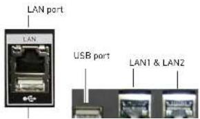
a Connect an Ethernet cable to the LAN port (DH230)

Figure 1.0 Connect BNC cameras to the system
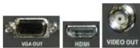
Figure 1.1 Connect to a VGA, HDMI or Video Out | USB port shown below
text_image
LAN port LAN USB port LAN1 & LAN2DH230: FRONT PANEL
text_image
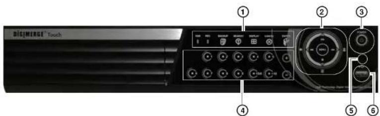
BIGMERGE Touch ① ② ③ ④ ⑤ ⑥1. Indicators:
• HDD: Flickers green to indicate hard drive activity.
• REC: Glows red to indicate system is recording.
- Backup: Opens the backup menu.
- Search: Opens the time-search menu.
• Display: Change split-screen views.
- Enter: Press to confirm a selection within menus.
- Cancel: Press to exit from menus. In the main viewing window, press to toggle the on-screen display on/off (i.e system time, recording indicators).
2. Navigati on cursor:
- Use the direction cursors | ◀ ▶ ▲ ▼| to navigate the system menus.
During Playback:
DH230: Front Panel
- Press to open the Main Menu, and to confirm menu selections.
• : Press to open the Log-In window. - Press to display the system Log.
• :Press to confirm menu options/selections/ enter sub-menu options. - : During Playback and menu navigations, press to exit the menu. In Live view, press to toggle the OSD on/off.
- Press to toggle the Alarm window (appears on the top of the screen). The alarm window displays any alarms that has triggered on the system.
3 PO WER: Press to power the system ON/OFF (password required. Default password = 000000)
DH230: REAR PANEL
text_image
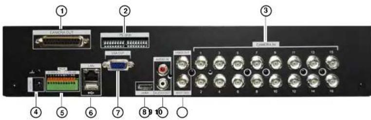
Labeled diagram of a computer rack showing ports, connectors, and audio equipment with numbered annotationsRear panel (16-channel model shown)
- CAMERA OUT (16 channel only): Port for octopus cable (16-channel models only). Connect up to 16 additional Loop Out monitors.
- 75 Ohm (16-channel only): Controls the DVR's impedance when using loop-out monitors. This prevents the colors connected to loop-out monitors from being "washed out".
- CAM ERA IN: Camera input ports for BNC cameras
- DC 12V: Port for 12V DC 5A (4-channel) / DC 6A (8/16 channel) power supply (included).
- ALARM IN: Alarm block to connect external alarm or motion devices (not included).
• RS422 : Connection block for an RS422 PTZ camera (not included). - LAN: Connect an Ethernet cable to connect the system to a router or switch (not included).
- USB port: connect a USB mouse, USB memory key, or external hard drive.
- VGA: VGA port to connect the system to a VGA monitor.
- HDMI: HDMI port to connect the system to a HDMI TV/monitor.
NOTE: The HDMI and output to the software resolution of \$1000, 1000; However, the software
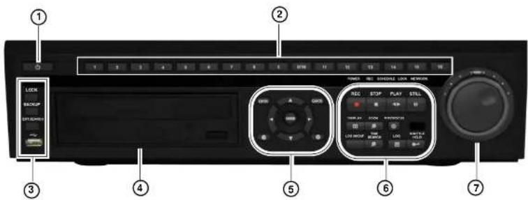
DH250: FRONT PANEL
text_image
1 2 3 4 5 6 7 8 9 10 11 12 13 14 15 16 17 18 19 20 21 22 23 24 25 26 27 28 29 30 31 32 33 34 35 36 37 38 39 40 41 42 43 44 45 46 47 48 49 50 51 52 53 54 55 56 57 58 59 60 61 62 63 64 65 66 67 68 69 70 71 72 73 74 75 76 77 78 79 80 81 82 83 84 85 86 87 88 89 90 91 92 93 94 95 96 97 98 99 100- Power Button: Press to power on/off the system (Password required).
- Number Ke ys: Press to view channel in full screen mode. The 0/10 button acts as channel 10 when pressed during live view. Within menus, press the number keys to enter numbers. The 0/10 acts as "0" when pressed within menus.
-
Lock, Backup, and Search:
-
LOCK: Press to lock the system.
- BACKUP: Press to open the back up menu.
- EXT.SEARCH: Press to open the External Search menu. The External Search menu searches for video on external storage devices (i.e. external USB hard drive).
-
USB: Connect an external USB device (i.e. USB mouse or external USB hard drive).
-
DV D-RW: Insert a blank CD-R / DVD-R media to back up video files.
5 Mavinati on buttons.
- LOG IN / LOG OUT: Press to log in / log out of the system (password required)
• TIME SEARCH: Opens the time search menu.
• LOG: Opens the system log menu. - SHUTTLE HOLD: During the fast forward, or reverse playback mode using the Jog Ring/Shuttle wheel, press the SHUTTLE HOLD button to lock the playback speed.
- Jog Ring / Shuttle Wheel: Use the Jog Ring/ Shuttle Wheel to fastforward or rewind video during playback.
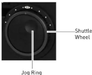
text_image
Shuttle Wheel Jog RingUsing the Shuttle Wheel
During playback, twist the shuttle wheel clockwise to increase the playback speed. The further you turn the shuttle wheel, the faster the system fast forwards. Release the shuttle wheel to pause playback. The same applies when twisting the shuttle wheel counter-clockwise, except the video plays backwards (reverse playback).
Using the Jog Ring
The Jog Ring allows you to play video frame-by-frame (advance frame) during playback.
To use the Jog Ring, pause the video, then turn the shuttle wheel forward or backward to play video frame-by-frame.
DH250: REAR PANEL

text_image
Labeled diagram of a network equipment rack with numbered components and ports- CAMERA IN: Camera input ports for BNC cameras.
- CAM ERA OUT: Connect up to 16 additional Loop Out monitors.
- AC IN: Connect a power cable to the AC IN port. Connect the other end of the cable to a power outlet.
4.75 OHMS: Controls the DVR's impedance when using loop-out monitors. This prevents the colors connected to loop-out monitors from being "washed out". - AUDI O IN: Connect an audio-in octopus cable (9-pin to RCA) to connect up to 16 audio-enabled cameras or powered mic (not included).
- AUDI 0 OUT: Connect one 3.5" RCA port [mono] for audio output.
- VIDEO OUT: Video output (BNC) to connect the system to a secondary monitor or DVR.
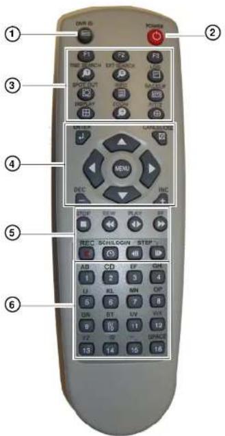
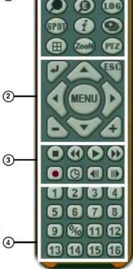
Remote Control
REMOTE CONTROL
- DVR ID: Pairs the DVR with the remote (optional). For details, see "GENERAL" on page 56.
-
POWER: Press to power the system ON/OFF (password required).
-
S ystem configuration buttons:
• TIME SEARCH: Press to open the Time Search menu.
- EXTERNAL-SEARCH: Press to open the External Search menu. The External Search menu allows you to browse for content on an external hard drive connected to the DVR.
• LOG: Press to open the system log.
- SPOT OUT: Press to select SPOT OUT output.
• INFO: Press to view vital system information.
• BACKUP: Press to open the Backup Menu.
- DISPLAY (☐): Press to switch between single channel full-screen, quad, and split-screen displays.
• ZOOM: Press to open the zoom field (live view, single channel only). Press ENTER to zoom in.
• P/T/Z: Press to open the PTZ menu.
-
Navigatio n/Menu:
-
▲: Press to move cursor up
- ▼: Press to move cursor down
•◀: Press to move cursor left
• ▶: Press to move cursor right - MENU: Press to open the Main Menu, and to confirm

text_image
1 2 3 4 5 6 7 8 9 10 11 12 13 14 15 16 F1 F2 F3 TIME SEARCH GET SPACE SCHOOL SMOODING PICKLE PICKLE PICKLE PICKLE PICKLE PICKLE PICKLE PICKLE PICKLE PICKLE PICKLE PICKLE PICKLE PICKLE PICKLE PICKLE PICKLE PICKLE PICKLE PICKLE PICKLE PICKLE PICKLE PICKLE PICKLE PICKLE PICKLE PICKLE PICKLE PICKLE PICKLE PICKLE PICKLE PICKLE PIP PICKLE PICKLE PICKLE PICKLE PICKLE PICKLE PICKLE PICKLE PICKLE PICKLE PICKLE PICKLE PICKLE PICKLE PIP PICKLE PICKLE PICKLE PICKLE PICKLE PIP PICKLE PIP PICKLE PIP PICKLE PIP PICKLE PIP PICKLE PIP PICKLE PIP PICKLE PIP PICKLE PIP PICKLE PIP PICKLE PIP PICKLE PIP PICKLE PIP PICKLE PIP PICKLE PIP PICKLE PIP PICKLE PIP PICKLE PIPC PICKLE PIP PICKLE PIP PICKLE PIP PICKLE PIP PICKLE PIP PICKLE PIP PICKLE PIP PICKLE PIP PICKLE PIP PICKLE PIP PICKLE PIP PICKLE PIP PICKLE PIP PICKLE PIP PICKLE PIP PICKLE PIP PICKLPGK PICKLPGK PICKLPGK PICKLPGK PICKLPGK PICKLPGK PICKLPGK PICKLPGK PICKLPGK PICKLPGK PICKLPGK PICKLPGK PICKLPGK PICKLPGK PICKLPGK PICKLPGK PICKLPGK PICK LSPGK PICK LSPGK PICK LSPGK PICK LSPGK PICK LSPGK PICK LSPGK PICK LSPGK PICK LSPGK PICK LSPGK PICK LSPGK PICK LSPGK PICK LSPGK PICK LSPGK PICK LSPGK PICK LSPGKRemote Control
5. Playback controls:
• ■: Press to stop playback
- Press repeatedly to increase reverse playback speed
- ◀: Press to begin playback; press to switch between forward and reverse playback
- ▶: Press repeatedly to increase forward playback speed
• : Press to start/stop manual recording.
- SCH/LOGIN: Opens the Login window to log in or out of the system.
- and ▶ During playback, press to pause; press repeatedly for frame-by-frame playback
- Channel buttons: Press to view channels 1-16 individually in full-screen; press to input passwords; when entering camera titles, press for alpha-numeric characters. Note that the 0/10 button means "0" when entering passwords, and "10" when accessing channel 10 [16-channel models only].
text_image
① ② ③ ④ ⑤ ⑥ DNR ID POWER F1 F2 F3 TIME SEARCH EXT scanning BACKOUT ADC SATCH HOLD ON OFF SPEED SMOOD PICKER MENU DEC INC STOP PLAY SET REC SCHLOGN STEP AB CD EF GM U BL MN OP 5 6 7 8 DR ST LN WIN 6 10 11 12 22 23 SPACE 13 14 15 16You can use the channel buttons on the remote control to enter numbers, letters, and other characters.
Remote Control
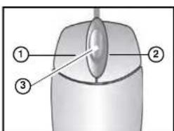
Mouse Control
The mouse is the primary control device for the system. To connect a USB mouse:
- Connect a USB mouse to the USB port on the front or rear panel.
- Left-Button: While in a split-screen display mode, double-click an individual channel to view it in full-screen; double-click again to return to the split-screen display mode. While navigating menus, click to select a menu option; double-click to open the next menu.
- Right -Button: Right-click anywhere on the screen to open the Virtual Remote; double-click anywhere on the screen to return to the previous menu.
- Scr oll-Wheel: Move the scroll wheel up or down to increase/decrease the value of a selected menu option.
Mouse Tips
When using the mouse, the ENTER and EXIT buttons appear in the top-right corner of every menu window. When you change system settings and configurations, click ← [ENTER] to save your changes.
text_image
Diagram of a computer mouse with labeled parts: head, lens, and screen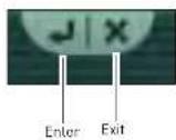
Touch Screen Control
A touch screen monitor (not included) can be used as a substitute for mouse control. Touch screen monitors must be Windows 7® Touch compatible to work with the system.
To connect a touch screen monitor:
- Connect a USB cable (not included) from a USB port on the front or rear panel of the system to the monitor.
- Connect a VGA cable (not included) from the VGA OUT port on the rear panel to the monitor, OR • Connect an HDMI cable (not included) from the HDMI port on the rear panel to the monitor.
- Power on the monitor, and then power on the system.
Remote Control
Touch Panel Tips and Tricks (DH230 only)
If using the Touch panel, you will often use the following buttons when controlling the system:
- II ▶: Menus: move cursor up; Playback: pause playback; Live viewing: show/hide OSD/ Alarm OSD;
- Menus move cursor down; Playback: stop playback; Live viewing: open Log menu
- «/●: Menus: move cursor left; Playback: increase reverse playback speed; Live viewing: start/stop recording
• Menus: move cursor right; Playback: increase forward playback speed; Live viewing: open the log in window. - Press the MENU button to open the main menu AND close windows/exit. Press the MENU button to confirm menu selections.
NOTE: This manual refers to the CANCEL/ESC button on the remote control for closing/exiting menu windows. If using the front panel, press MENU/ESC to close/exit menu windows.

natural_image
Circular device control panel with playback buttons and a central 'MENU' button (no text or symbols beyond basic icons)- Press the button to increase values for selected menu options
- Press the button to decrease values for selected menu options
- Press the Button to confirm a selection.
Using the System
USING THE SYSTEM
The default system password is 000000
To power the system ON:
- Connect the power cable to the port on the rear panel.
- Press the POWER button on the front panel or remote control.
To power the system OFF:
- Press the Stop button | ■| to halt system recording.
- Enter your system password.
- Press the PO WER button on the front panel or remote control.
- Enter your system password to shut down the system.
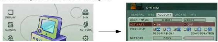
Password
The default system password is 000000. You can configure the system password through the Main Menu>System>ACCOUNTS. For complete information on changing your password and managing users on the system, see "ACCOUNT" on page 56.
text_image
DISPLAY CAMERA DISK NETWORK SYSTEM GENERAL TIME ACCOUNT UPDATE INFO USER / NAME USER 1 USER1 ACTIVATE ON OFF PRIVILEGE DESCRIPTION CONFIGURATION NETWORK DENYUsing the System
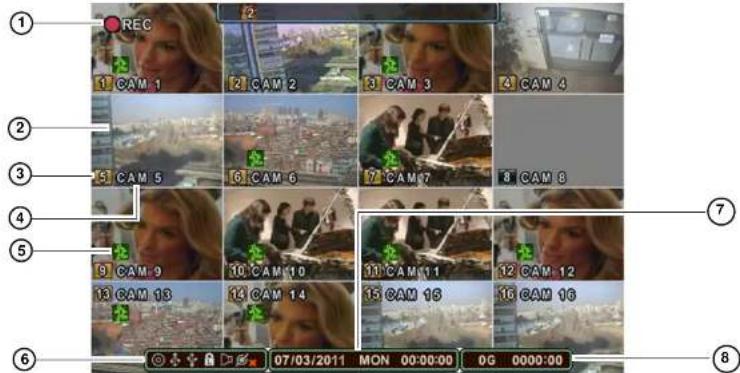
On-Screen Display
The system shows the following for all display views:
text_image
1 REC 2 CAM 1 CAM 2 CAM 3 CAM 4 CAM 5 CAM 6 CAM 7 CAM 8 CAM 9 CAM 10 CAM 11 CAM 12 CAM 13 CAM 14 CAM 15 CAM 16 07/03/2011 MON 00:00:00 0G 0000:00- Recording Indicator: "REC" indicates that continuous recording is enabled on at least one channel. NOTE: If REC does not appear on the onscreen display the system is NOT RECORDING.
- Display: Show live video and playback in single channel full-screen, quad, and split-screen configurations.
- Recording Status & Channel indicator (1 2 3): The number indicates the channel number. The colors have different meanings:
- Black: No recording in program
Using the System
6. Status Indicators

text_image
CD/DVD Drive Indicator USB Indicator (Rear panel) Audio Indicator User Status Connected Users- CD/DVD Drive Indicator: Indicates that a CD/DVD writer is connected to the DVR. The indicator glows blue when CD/DVD burning is in progress.
- USB Indicator (Front panel): Glows blue when a USB device is connected the front USB port to perform a system backup.
- USB Indicator (Rear panel): Glows blue when a USB device is connected the rear USB port to perform a system backup.
- User Status: Indicates what type of user is currently logged in.
• : The system administrator is logged in.
• : A user is logged in.
• The system is locked.
- Audio Indicator: During video playback, if there is audio present, the Audio Indicator glows blue.
-
Connected Users: Shows the number of users who are connected to the system via the network (i.e through the web browser or smartphone).
-
Date/Time: Shows the date (mm/dd/yyyy), day of the week, and time (24-hour clock).
07/03/2007 MON 00:00:00
Using the System
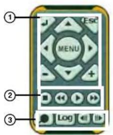
Using the Virtual Remote
Right-click anywhere on the screen to open the Virtual Remote. The Virtual Remote gives you quick access to many of the system's features using only a USB mouse (included).
- Quick Function Keys:
• Time Search
- PTZ: Opens the PTZ menu.
• :Window
Positioning
- Log
- Spot Out
- i System Info
- Backup
- □: Display
Mode
• :External Search
-
Navigation/Menu:
-
▲: Move cursor up
- ▼: Move cursor down
- Move cursor left
- Move cursor right
- MENU: Press to open the Main Menu, and to confirm menu selections.
• ← : Press to confirm menu options/selections/enter sub-menu options. - ESC: Close menu windows; press to show/hide the onscreen display (OSDI); press to clear channel indicators (loss, alarm, etc.)
• +: Increase values in menu options. -
: Decrease menu options in menu options
-
Playback controls:
• ■: Stop playback / stop system recording
①
text_image
② ③ ④ MENU ESCUsing the System
Playback
During playback, you can right-click anywhere on the screen to open a condensed version of the Virtual Remote.
-
Navigation/Menu:
-
▲: Move cursor up
- ▼: Move cursor down
- Move cursor left
- ▶: Move cursor right
- MENU: Opens system's main menu.
• ← : Click to confirm menu options/selections - ESC: Click to close menu windows; click to show/hide the onscreen display (OSD); click to clear channel indicators (loss, alarm, etc.)
• +: Increase values in menu options. - : Decrease menu options in menu options
text_image
① ESC MENU ② LogVirtual Remote during Playback
-
Playback controls:
-
■: Stop playback
- Increase reverse playback speed 1X, 2X, 4X, 8X, and 16X
- : Start playback; press to switch between forward and reverse playback
-
▶: Increase forward playback speed 1X, 2X, 4X, 8X, and 16X
-
Quick Function Keys:
-
Click to open the Time Search menu
- Log: Click to open the Log menu
- ◀: During playback, click to pause; click repeatedly for frame-by-frame playback
- ▶: During playback, click to pause; click repeatedly for frame-by-frame playback
Using the Virtual Keyboard
Using the System
Setting the Time
It is highly recommended to set the time on the system prior to doing any recording.

All recording must be stopped on the system in order to set the time.
To set the date and time:
- Stop recording on the system by pressing ■ on the front panel, or press the ■ button on the remote control and enter your 6-digit system password (by default, 000000). NOTE: If using the mouse, right-click and then click ■ on the Virtual Remote.
- Press the MENU button to open the system menu. Select SYSTEM and press the ENTER button. The System menu opens.
- Select the TIM E tab.

text_image
SYSTEM GENERAL TIME ACCOUNT UPDATE INFO TIME ZONE GMT+09:09 (STANDARD) DATE FORMAT YYYY/MM/DD NTP SYNC ON OFF NTP SERVER NTP TEST START DATE 2011/33/04 (YYYY/MM/DD) TIME 08:09:00 (HH MM SS) Date Time- Select DA TE and enter the date (yyyy/mm/dd).
- Select TIME and enter the time (hh/mm/ss).
Using the System
Multi-Screen Display
The system can display channels in full-screen single channel, quad, and multi split-screen displays.

Full-Screen

Quad

Split-Screen 1

Split-Screen 2
[16-channel models only]
Repositioning Channels
You can reposition the channels on the display screen. This can be very useful when monitoring a live location(s).
To reposition the display channels using a mouse:
- Using the mouse, remote control, or front panel, place the main display screen in either a quad display, or in a multi split-screen configuration.
NOTE: Repositioning will not work if the main display screen is in full-screen single channel.
- Using the mouse, right-click anywhere on the screen to open the Virtual Remote.
- From the Virtual Remote, click (typically channel 1). The Blue Window cursor appears in the top-left channel
-
Reposition the channels through the following:
-
Remote Control: Press the button for the channel you wish to place in the location of the Blue Window cursor. For example, if the cursor is on channel 1, and you want to have channel 4 in its location, press the 4 button on the remote control. You can also press F2 on the remote to open the Blue Window cursor, then press the desired channel number that you wish to change to
- Front Panel: Press the button for the channel you wish to place in the location of the Blue Window cursor


Using the System
To reposition the display channels using a touch screen monitor:
- Place the main display screen in either a quad display, or in a multi split-screen configuration.
NOTE: Repositioning will not work if the main display screen is in full-screen single channel.
- Press and hold inside the channel you would like to move. Drag your finger to the channel you wish to reassign it to and release.
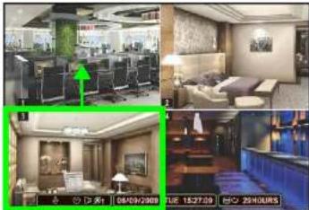
natural_image
Interior view of a modern hotel lobby with large windows, seating areas, and a blue counter (no visible text or signage)Press and hold inside channel 3 and drag your finger to move channel 3 to the channel 1 position.
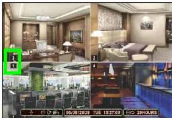
natural_image
Interior and exterior views of a modern living room with furniture and seating (no visible text or symbols)Channels repositioned Channel 3 is now in the channel 1 position.
NOTE: If the Virtual Remote appears while doing this, you may ignore it. After repositioning the channel, tap anywhere outside the Virtual Remote to exit.
RECORDING
By default, the system is set to immediately record at startup from connected cameras. This is called continuous recording. It is highly recommended to keep continuous recording on at all times.
The system can perform Continuous Recording, Event Recording, and Schedule Recording. However, the system can only perform one type of recording at a given time.
Continuous Recording
By default, all camera channels are enabled with continuous recording. During Continuous Recording, the REC icon appears in the top left corner of the OSD.
REC icon
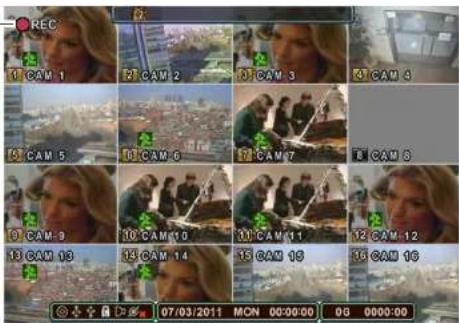
text_image
REC 1 CAM 1 2 CAM 2 3 CAM 3 4 CAM 4 5 CAM 5 6 CAM 6 7 CAM 7 8 CAM 8 9 CAM 9 10 CAM 10 11 CAM 11 12 CAM 12 13 CAM 13 14 CAM 14 15 CAM 15 16 CAM 16 07/03/2011 MON 00:00:00 00 0000:00Continuous recording on all channels (4CH model shown)
• In this example, Continuous Recording is on ALL channels (default)
Recording
Motion
When motion is detected, the system will continue to record, but can apply unique recording parameters for each camera that you can set in the EVENT and DAY EVENT MENU [Main Menu → Record → DAY or NIGHT (EVENT) → DAY or NIGHT EVENT]. The camera enabled with Motion Detection will have a RED icon number on the OSD.
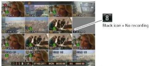
text_image
8 Black icon = No recordingMotion assigned to channels [16-channel model shown]
NOTE: A black icon indicates that recording on a camera is disabled. For better security it is highly recommended to keep continuous recording for all cameras on at all times. Use caution when assigning motion detection to specific cameras.
When motion is detected by the camera, the motion icon will appear.

text_image
Screenshot of a video editing interface with multiple video thumbnails and timecode display at bottomMotion was detected on the DVR (16 CH model shown)

Recording
Schedule Recording
Schedule Recording can be set manually or at startup. Schedule Recording features customizable recording parameters that you assign to each camera.
ATTENTION: Schedule Recording takes priority over all other recording modes.
To access the Schedule Recording tab:
- Press the MENU button on the front panel, or virtual remote (right-click → MENU).
- Click RE CORD.
- In the GENERAL tab, Under SCHEDULE USE, select ON.
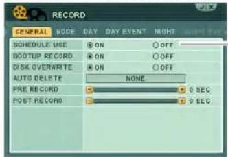
text_image
RECORD GENERAL NODE DAY DAY EVENT RIGHT SCHEDULE USE ON OFF BOOTUP RECORD ON OFF DISK OVERWRITE ON OFF AUTO DELETE NONE PRE RECORD 0 SEC POST RECORD 0 SECSchedule Use
- Click the DAY, DAY EVENT tabs to configure scheduled recording.
For details on scheduled recording, see "RECORD" on page 41.
Recording Audio
The system can record one channel of audio. You must have an audio enabled camera or self-powered microphone connected to the system in order to use this function. For details on connected audio recording devices, see "Appendix K: Using Listen-in Audio" on page 176.
PLAYBACK
View recorded video on the system through playback mode.
Playback speed indicator
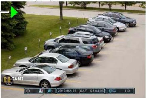
natural_image
Exterior view of a row of parked cars in an outdoor parking lot, no visible text or signagePlayback display view
To begin playback:
- Select the number of channels you wish to playback [i.e singl e channel, or quad view etc.]
- Press the Play button (◀) on the remote control or press ▶ on the Virtual Remote. The system will play the last few minutes of the most recently recorded video.
- Press the following buttons on the remote control to use playback functions:
• ◀: Press to switch between forward and reverse playback
- Press to pause playback; press repeatedly for frame-by-frame reverse playback
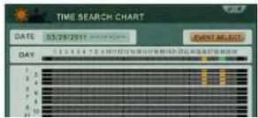
SEARCH
Search for recorded video data on the system using the Time Search menu.
To open the Time Search menu:
- Press the Search button ( [T] ) on the front panel or remote control ( [O])
text_image
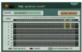
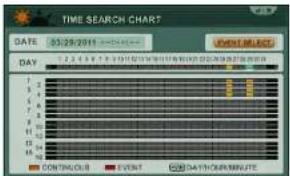
TIME SEARCH CHART DATE: 03/28/2011 EVENTS ADDRESS DAY CONTINUOUS EVENT DAYHOUR MAILUTETo search for recorded video with Multi-channel playback:
- Beside the "Day" field, click on the date you wish to search for. Then scroll DOWN (or click + on the virtual remote) on the mouse to select the Hour. Select the desired hour. Scroll DOWN (or click + on the virtual remote) again to select the desired minute.

text_image
TIME SEARCH CHART DATE 03/29/2011 EVENT SEARCH DAY 1 2 3 4 5 6 7 8 9 10 11 12 13 14 15 16 17 18 19 20 21 22 23 24 25 26 27 28 29 30 Select the date, hour, and minute Enter button - button + button CONTINUOUS EVENT DAYHOUR MINUTESearch
Quick Search
To perform a quick search:

- Press and hold the Sear ch Button ( ☑ ) on the front panel of the system for 2 seconds. The Time Input menu appears.

text_image
TIME INPUT INPUT 2011/02/25 00:00 BEGIN 2011/01/27 03:49:10 END 2011/02/25 06:15:43- Double-click the INPUT field, and use the virtual k-eyboard to enter the date and time that you wish to search for.
Event Record Search
The Event Record Search option allows you to search for any events that occurred on the system.
To perform an Event Record Search:
- Press the SEARCH button ( [IMAGE] ) on the front panel or remote control ( [IMAGE]).
text_image
TIME SEARCH CHART DATE 03/29/2011 EVENT BLOCKS DAY 1 2 3 4 5 6 7 8 9 10 11 12 13 14 15 16 17 18 19 20 21 22 23 24 25 26 27 28 29 30 31 32 33 34 35 36 37 38 39 40 41 42 43 44 45 46 47 48 49 50 51 52 53 54 55 56 57 58 59 60 61 62 63 64 65 66 67 68 69 70 1 2 3 4 5 6 7 8 9 10 11 12 13 14 15 16 17 18 19 20 21 22 23 24 25 26 27 28 29 30 31 32 33 34 35 36 37 38 39 40 41 42 43 44 45 46 47 48 49 50 51 52 53 54 55 56 57 58 59 60 61 62 63 64 65 66 67 68 69 70 71 72 73 74 75 76 77 78 79 80 81 82 83 84 85 86 87 88 89 90 91 92 93 94 95 96 97 98 99 100Search
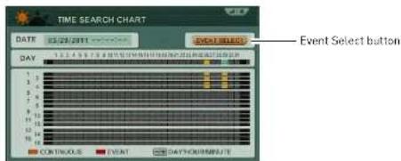
Event Preview Search
The Event Preview search allows you to view searched results as a thumbnail preview. This works in single-channel search only.
To perform a preview search:
- Press the Search button
T) on the front panel or remote control ( )
text_image
TIME SEARCH CHART DATE 05/29/2011 EVENT SELECT DAY 1 2 3 4 5 6 7 8 9 10 11 12 13 14 15 16 17 18 19 20 21 22 23 24 25 26 27 28 29 30 DOWING CLUB EVENT DATA DOWING MINUTE- Beside the "Day" field, click on the date you wish to search for. Then scroll DOWN on the mouse to select the Hour. Select the desired hour. Scroll DOWN again to select the desired minute. You can also press the -/+ button on the virtual remote to select the hour and minute.
- Right-click to open the virtual remote, and then click on the channel that you wish to preview search.

text_image
TIME SEARCH CHARTCH 1) DATE: 2011/02/25 00 HOUR 06:00:00 06:35:00 09:10:00 09:15:00 00:20:00 08:25:00 04:30:00 04:33:00 07:40:00 07:45:00 09:50:00 09:55:00Figure 10.7 Time Search Chart - Preview mode
Search
Motion Area Search
The Motion Area Search allows you to search for video with a pre-defined criteria.
To begin Event Area Search:
- Press the Search button ( ) on the front panel or ( ) on the virtual remote.
- Click on the date that you wish to search for. Right-click to open the Virtual Remote. Click the + button to select the hour. After you have selected the hour, click the + button again to select the desired minute you wish to search under.
- Click the Event Select button.
text_image
TIME SEARCH CHART DATE: 12/27/2011 EVENT SELECTED DAY 1 2 3 4 5 6 7 8 9 10 11 12 13 14 15 16 17 18 Event Select button CONTINUOUS EVENT DAYCHIMMEN/18- Double-click the Search Mode field, and click +/- to select MO TION AREA. Note that by default, the entire motion area is selected by default.
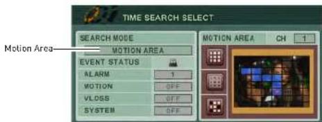
text_image
TIME SEARCH SELECT SEARCH MODE MOTION AREA Motion Area EVENT STATUS ALARM 1 MOTION OFF VLOSS OFF SYSTEM OFF- In the Motion Area window, configure the area of the screen that you wish to search for
Search
External Search
External search allows you to search for video footage stored on an external device such as an external hard drive. Note that the DVR can only search for video that is from the same model DVR.
Prerequisites:
- A USB 2.0 hard drive with data backed up from the same model DVR
To perform an External Search:
-
Connect a external USB hard drive to the USB port on the front or rear panel of the system.
-
Right-click to open the virtual remote, and then click .
- Enter your system password if required.
- In the EXTERNAL SEARCH menu, click -/+ and select the external device that you wish to search.
- Press the ENTER button. The system scans the external hard drive.
- The Time Search menu appears. Perform a search to search for videos on your external hard drive.
Event Source Search
Event Source search allows you to search for video on channels that have an alarm, motion, or video loss event.
To perform an Event Source search:
- Press the Search button ( ☑ ) on the front panel or [ ] on the virtual remote.
- Click on the date that you wish to search for. Right-click to open the Virtual Remote. Click the + button to select the hour. After you have selected the hour, click the + button again to select the desired minute you wish to search under.
- Click the Event Select button.
- Under SEARCH MODE click 1/4 and select EV ENT SOURCE
Setting up Sequencing
SETTING UP SEQUENCING
Sequencing allows you to view channels in a rotating interval. There are three modes of sequence setup : sequence mode, shift mode, and event mode.
Sequence mode & Shift mode
Sequence mode allows you to display channels on a regular rotating interval. For example, the monitor can display channels 1\~4, then channels 5\~8. Shift sequence mode retains the same split screen view, but the channels change continuously within each channel cell.
To set up regular sequence mode:
-
Press the MENU button on the remote or front panel to open the main menu. Press ENTER • If using a mouse, right-click to open the virtual remote, then click MENU.
-
Click DISPL AY.

text_image
Display CAMERA CAMERA NETWORK DEVICE SCHEDULE- Click the SWIT CH tab.

Setting up Sequencing
Event View
Event view allows the channel that detects an event (i.e. motion or alarm) to appear in the main channel. This is especially useful if you set up sequence in single-channel view, but want to see immediately any channels that detect motion.
To set up Event sequence mode:
- Press the MENU button on the remote or front panel to open the main menu.
- If using a mouse, right-click to open the virtual remote, then click MENU.
- Click DISPLA Y.
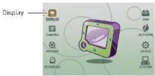
text_image
Display Xeroxide Camera Windows System- Click the SWIT CH tab.

text_image
DISPLAY GENERAL SWITCH DEVICE MAIN DRILL TIME MODE S GURNCE SHIFT EVENT SPLIT MODE USE CHANNEL-
Beside DEVICE, select MAIN or SPOT.
-
Configure the following:
• MODE: Select EVENT
- SPLIT MODE (MAIN configuration only): Select the desired split-screen style.
Setting up Sequencing
- Exit to the main viewing window. Press and hold the DISPLAY button for 2 seconds on the remote or front panel to begin sequence view. To exit sequence view, press DISPLAY on the remote or front panel or press the camera number on the remote.
Configuring the EVENT tab
The EVENT tab allows you to set up cameras to trigger each other. For example, you can set up Camera 1 (front door) to trigger Camera 5 (side door) to be the main channel when someone approaches Camera 1 (front door).
Scenario: Camera 1 triggers camera 5 to be the main camera
- Beside CH1, select camera 5 under MO TION.
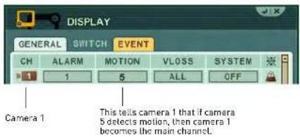
text_image
DISPLAY GENERAL SWITCH EVENT CH ALARM MOTION VLOSS SYSTEM 1 1 5 ALL OFF Camera 1 This tells camera 1 that if camera 5 detects motion, then camera 1 becomes the main channel.- Click EN TER to save your settings.
Connecting a SPOT OUT / CAMERA OUT monitor (DH230/250)
The SPOT OUT and VIDEO OUT ports allow you to connect addition monitors as outputs.

text_image
Circuit board layout with labeled components including VGA, audio jack, and control knobsDH230
Motion recording allows the system to mark events as motion recording. This allows you to search for footage that only has movement.
Step 1: Configure Camera motion sensitivity & Configure Event frame rates
- Press the MENU button on the remote or front panel to open the main menu. • If using a mouse, right-click to open the virtual remote, then click MENU.
- Click CA MERA.
- Click the camera number button to select the camera you wish to configure.
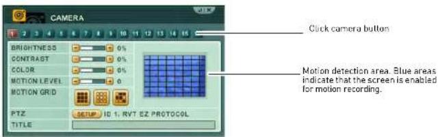
text_image
CAMERA BRIGHTNESS 0% CONTRAST 0% COLOR 0% MOTION LEVEL 0 MOTION GRID PTZ SETUP ID 1. RVT EZ PROTOCOL TITLE Click camera button Motion detection area Blue areas indicate that the screen is enabled for motion recording.- Click the [ ] button to select the entire screen (selected by default) or click [ ] to select certain portions of the screen by double-clicking the portions of the screen you wish to enable motion.
- Beside MOTION LEVEL, press -/+ to adjust the motion sensitivity.
-
Click EN TER to save your settings.
7 Click RE CORD→DAY. -
Under EVENT, enter the number of frames you want the camera to record in if it detects motion, under F/S. Repeat for any other cameras that you wish to enable motion recording.

text_image
RECORD GENERAL MODE DAY DAY EVENT CH RES. CONTINUOUS EVENT F/S QUALITY F/S QUALITY CIF 30 HIGH OFF SUPER 18 SUPER CIF 30 HIGH OFF SUPER CIF 30 HIGH OFF SUPER CIF 30 HIGH OFF SUPER CIF 30 HIGH OFF SUPER CIF 30 HIGH OFF SUPER CIF 30 HIGH OFF SUPER CIF 30 HIGH OFF SUPERNOTE: If you want to disable continuous recording, under CONTINUOUS, under F/S, select OFF. This causes the system to record only when the cameras detect motion.
- Under QUALITY, enter the desired video quality when the camera detects motion.
- Click ENTER to save your settings.
Step 2: Configure Cameras that have motion Enabled
- Click the DA Y EVENT tab.
- Ensure that under MOTION, the camera number matches the number in CH.
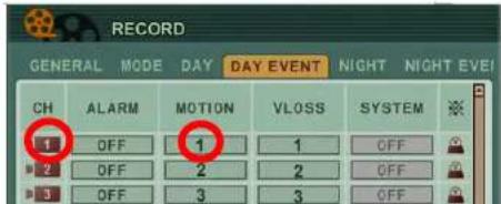
It is critical that the camera number under MOTION is the same as the channel number you are configuring.
This ensures that when there is motion to that particular camera, that it will trigger motion recording.
Setting up Motion Recording
- Double-click the days that you wish to enable Motion recording.

text_image
SCHEDULE CHART HOLIDAY 2 4 6 8 10 12 14 16 18 20 22 SUN MON Double-click on the day to configure.- Configure the following:
- MODE: Click the +/- buttons to change to apply DAY recording, or NO REC to disable recording. If you configured DAY recording in Step 1, select DAY.
NOTE: You cannot configure NIGHT recording to have a beginning and end time. However, if NIGHT recording is chosen, the NIGHT recording parameters still apply to the schedule.
- BEGIN: Enter the time you want the scheduled recording to start. - END: Enter the time you want the scheduled recording to end.
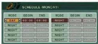
- Click EN TER to save your settings.
Final Result

Setting up Motion Recording
Triggering secondary cameras in Motion recording
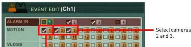
You can configure secondary cameras to begin motion recording when surrounding cameras detect motion. For example, if Camera 2 and 3 detects motion, the system can trigger Camera 1 to begin recording as an event.
To configure custom Motion recording settings:
- Under the DAY EVENT or NIGHT EVENT tab, click [] beside the channel that you wish to configure.

- Under MOTION, ensure that whatever channel y ou are configuring is selected. In this example, Camera 1 must be is selected, since it is the camera you are configuring. Select cameras 2 and 3.
Example
text_image
EVENT EDIT (Ch1) ALARM IN MOTION VLOSS 1 2 3 4 1 2 3 Select cameras 2 and 3.Setting up Motion Recording
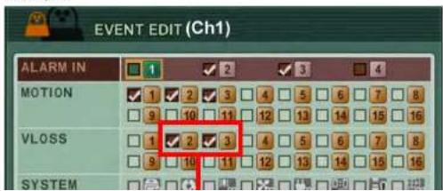
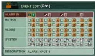
Triggering cameras to record during Video Loss
If video loss occurs, the system can trigger secondary cameras to begin recording as an event. For example, if a vandal attempts to cut the camera wiring, as soon as the cable wire is cut, the system triggers other cameras to detect as a motion event.

- Under the DAY EVENT or NIGHT EVENT tab, click [] beside the channel that you wish to configure.

text_image
RECORD GENERAL MODE DAY DAY EVENT NIGHT NIGHT EVEI CH ALARM MOTION VLOSS SYSTEM 1 OFF 1 1 OFF 2 OFF 2 2 OFF 3 OFF 3 3 OFF Event Edition- Under VLOSS, ensure that whatever channel you are configuring is selected. In this example, Camera 1 is selected. Select cameras 2 and 3.
Example
text_image
EVENT EDIT (Ch1) ALARM IN MOTION VLOSS SYSTEMUsing the Main Menu
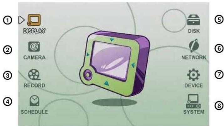
USING THE MAIN MENU
To open the Main Menu:
- Press the MENU button on the front panel or the remote control
text_image
① DISPLAY ② CAMERA ③ RECORD ④ SCHEDULE DISK NETWORK DEVICE SYSTEM ⑤ ⑥ ⑦ ⑧System Main Menu
- DIS PLAY: Adjust OSD borders, split-screen configuration, and Auto Sequence settings.
Using the Main Menu

DISPLAY
Use the Display menu to configure the OSD and Auto Sequence settings.

The Display menu categorizes in 3 sections --- "GENERAL", "SWITCH" and "EVENT".

Display Tab
- Click ENTER to save your changes and exit.
SWITCH / EVENT
The SWITCH and EVENT tab allows you to configure Sequencing display options for the main and spot out monitor.

text_image
DISPLAY GENERAL SWITCH EVENT DEVICE MAIN DWELL TIME 0 SEC MODE SEQUENCE SHIFT EVENT SPLIT MODE USE CHANNEL 1 2 3 4 5 6 7 8 5 10 11 12 13 14 15 16For details on setting up sequencing mode, see "Setting up Sequencing" on page 30.
GENERAL
To configure the "GENERAL" display tab:
-
Select the GE NERAL tab, and configure the following:
-
STATUS BAR: Select to Show or Hide the status bar on the OSD.
• CAMERA INFO: Select to show the CAMERA NUMBER, or the CAMERA TITLE or both.
Using the Main Menu

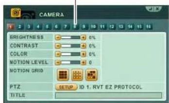
CAMERA
Configure various camera settings, such as brightness, contrast, and title.
To configure camera settings:
- Click the camera number button to configure the desired camera.
Camera number button
text_image
CAMERA GRIGHTNESS 0% CONTRAST 0% COLOR 0% MOTION LEVEL 0 MOTION GRID PTZ SETUP ID 1. RVT EZ PROTOCOL TITLE-
Configure the following:
-
BRIGHTNESS, CONTRAST, COLOR: Adjust from 0\~100.
- MOTION LEVEL: Select the motion sensitivity of the system. The greater the number, the more sensitive the system is to motion. By default, the motion level is set to 20.
- MOTION GRID: Select the area of the screen that you wish to enable motion recording.

- PTZ: Click the SETUP button to configure your PTZ settings. Enter your PTZ ID, Model, and Baudrate. The PTZ ID should match the camera channel to which you have connected the PTZ camera.

text_image
PTZ SETUP (CH 1) ID 0.1 MODEL PELCO. D BAUD RATE 9900 BPS TOUR GROUP 1 GROUP LIST 1) PRESET 1-3, 2 SEC PRESET NO. 601 START - 003 STOP DWELL TIME 02 SEC CHANGE INSERT MODIFY REMOVENOTE: PTZ devices are connected to the RS-422 ports located on the rear panel. Multiple PTZ cameras are connected by daisy-chaining the camera connection in the RS-422 ports.
NOTE: For details on connecting PTZ cameras, see "Appendix F: Connecting PTZ Cameras" on page 155.
• TITLE: Enter the desired camera title.
- Repeat for other camera connected to the system.
- Click ENTER to save your settings. Press CANCEL/ESC to close remaining menu windows.
Using the Main Menu

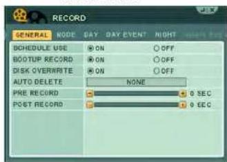
RECORD
Configure recording parameters for each channel.
text_image
RECORD GENERAL NODE DAY DAY EVENT NIGHT SCHEDULE USE ON OFF BOOTUP RECORD ON OFF DISK OVERWRITE ON OFF AUTO DELETE NONE PRE RECORD 0 SEC POST RECORD 0 SECGENERAL
To configure the GENERAL tab:
-
Click the GE NERAL tab (selected by default).
-
Configure the following:
-
SCHEDULE USE: Select ON to configure the NIGHT and NIGHT EVENT tab. By default, Schedule Use is turned off.
- BOOTUP RECORD: Turn this setting ON (default) so that the DVR begins recording automatically at system bootup. If this setting is turned off, the DVR will not record until you press the record button.
- DISK OVERWRITE: Turn this setting ON (default) so that the hard drive
time marked at 5 seconds, then during the search, the video will begin at 11:59:55.
- Click ENTER to save your changes.
- POST RECORD: Configure the amount of time the system marks an event after an event occurs. Select from 5 seconds - 300 seconds.
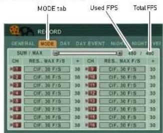
MODE
To configure the MODE tab:
Prerequisite: Stop the system recording before configuration. If the system is still recording, you will not be able to edit the settings in the MODE tab.
- Click the MOD E tab.
text_image
MODE tab Used FPS Total FPS RECORD GENERAL MODE DAY DAY EVENT NIGHT NIGHT VIE SUM / MAX 1.450 / 4x0 CH RES. MAX F/S + CH RES. MAX F/S + 1 CIF. 30 F/S 30 300 CIF. 36 F/S 30 2 CIF. 30 F/S 30 300 CIF. 36 F/S 30 3 CIF. 30 F/S 30 301 CIF. 30 F/S 30 4 CIF. 30 F/S 30 302 CIF. 30 F/S 30 5 CIF. 30 F/S 30 303 CIF. 36 F/S 30 6 CIF. 30 F/S 30 304 CIF. 36 F/S 30 7 CIF. 30 F/S 30 305 CIF. 36 F/S 30 8 CIF. 30 F/S 30 306 CIF. 36 F/S 30-
Beside the camera number that you wish to configure, set the following:
-
-
-
-
-
-
-
-
-
-
-
-
-
-
-
-
-
-
-
-
-
-
-
-
-
-
-
-
-
-
-
-
-
-
-
-
-
-
-
-
-
-
-
-
-
-
-
-
-
-
-
-
-
-
-
-
-
-
-
-
-
-
-
-
-
-
-
-
-
-
-
-
-
-
-
-
-
-
-
-
- 81.
-
-
-
-
-
-
-
-
-
-
-
-
-
-
-
-
-
-
-
-
-
-
-
-
-
-
-
-
-
-
-
-
-
-
-
-
-
-
-
-
-
-
-
-
-
-
-
-
-
-
-
-
-
-
-
-
-
-
-
-
-
-
-
-
-
-
-
-
-
-
-
-
-
-
-
-
-
-
-
Using the Main Menu
DAY
Configuring the DAY tab
The DAY tab allows you to configure how the system will record during DAY recording in the Scheduled recording menu.
To configure the DAY tab:
- Click the DA Y tab.

text_image
RECORD GENERAL MODE DAY DAY EVENT CH RES. CONTINUOUS EVENT F/S QUALITY F/S QUALITY CIF 50 HIGH OFF SUPER CIF 30 HIGH 10 SUPER CIF 30 HIGH OFF SUPER CIF 30 HIGH OFF SUPER CIF 30 HIGH OFF SUPER CIF 30 HIGH OFF SUPER CIF 30 HIGH OFF SUPER CIF 30 HIGH OFF SUPER- Beside the desired channel you wish to configure, adjust the following for Continuous and Event recording:
• Under F/S, select the frames per second of the particular channel during DAY recording.
• Under QUALITY, select the recording quality during daytime recording.
- Click EN TER to save your settings.
To configure the DAY EVENT tab:
- Click the DA Y EVENT tab.
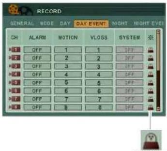
-
Configure the following for each channel:
-
ALARM: Select from 1\~4 or ALL. This tells the system to mark the video as an event when an alarm input triggers for the selected channel.
- MOTION: Select the camera that you want to trigger the camera being configured to record as an event. For example, if you are configuring channel 2, and enter channel 8 in the MOTION column, this tells the system that when a video loss occurs in channel 8, it will also cause channel 2 to record, and mark the recorded video as an event.
DAV EVENT
.10.05. 6.11.
Using the Main Menu

• [EVENT EDIT]: Click this icon to open the NIGHT tab allows you to configure how the system will record during Night recording in
text_image
EVENT EDIT (Ch1) ALARM IN MOTION VLOSS SYSTEM DESCRIPTION ALARM INPUT 1About the EVENT EDIT window
The EVENT EDIT window allows you to have other cameras trigger the camera you are configuring, to record as an event. For example, you can tell the system to have camera 1 record, when there is video loss in camera 3. Likewise, you can tell camera 1 to record as an event when there is motion detected in camera 5.
To configure the EVENT EDIT window:
-
Configure the following:
-
ALARM IN: Select the Alarm In devices that, when triggered, will cause the camera you are configuring to record as an event.
- MOTION: Set the camera (i.e. Camera A) that you want to trigger the system to record when the camera (Camera A).
NIGHT
Configuring the NIGHT tab
The NIGHT tab allows you to configure how the system will record during Night recording in the Scheduled recording menu.
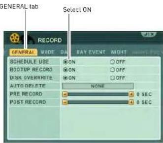
To configure the NIGHT tab:
- In the RECORD menu, click the GENER AL tab.
- Beside SCHEDULE USE, select ON.
text_image
GENERAL tab RECORD GENERAL MODE DA SCHEDULE USE ON OFF BOOTUP RECORD ON OFF DISK OVERWRITE ON OFF AUTO DELETE NONE PRE RECORD 0 SEC POST RECORD 0 SEC- Click the NIGHT tab

Using the Main Menu
NIGHT EVENT
Configuring the NIGHT EVENT tab
The NIGHT EVENT tab allows you to configure how the system will record during Night EVENT recording in the scheduled recording menu.

-
Configure the following:
-
ALARM: Select from 1\~4 or ALL. This tells the system to mark the video as an event when an alarm input triggers for the selected channel.
- MOTION: Select the camera that you want to trigger the camera being configured to record as an event. For example, if you are configuring channel 2, and enter channel 8 in the MOTION column, this tells the system that when a video loss occurs in channel 8, it will also cause channel 2 to record, and

the EVENT EDIT menu
About the EVENT EDIT window
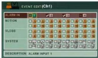
text_image
EVENT EDIT (Ch1) ALARM IN MOTION VLOSS SYSTEM DESCRIPTION ALARM INPUT 1The EVENT EDIT window allows you to trigger other cameras to record if an event is detected. For example, if the camera outside your garage (camera 5) detects movement, you can trigger the camera inside the garage (camera 6) to begin recording as an event.
To configure the EVENT EDIT window:
-
Configure the following:
-
ALARMIN: Select the Alarm In devices that will trigger an alarm recording.
- MOTION: Select the camera that will begin recording when motion is detected.
For example, if you are configuring channel
Using the Main Menu

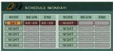
SCHEDULE
Set a custom recording schedule for the days of the week.

text_image
SCHEDULE CHART HOLIDAY 2 4 6 8 10 12 14 16 18 20 22 SUN MON TUE WED THU FRI SAT CUSTOM DAY NIGHT NO-RECPre-requisites:
- Ensure that you have configured the DAY and NIGHT recording settings in the Recording menu. Select NO REC to disable recording. For details, see "RECORD" on page 41.
CHART
To set a recording schedule in the CHART tab:
- Click the CHART t ab [default].
- Double-click the day that you wish to configure.

3. Configure the following:
- MODE: Click the +/- buttons to change to appl, DAY, NIGHT recording. Select NO REC to disable recording.
NOTE: You cannot configure NIGHT recording to have a beginning and end time. However, if NIGHT recording is chosen, the NIGHT recording parameters still apply to the schedule.
- BEGIN: Enter the time you want the scheduled recording to start.
• END: Enter the time you want the scheduled recording to end.
- Click ENTER to save your settings.
HOLIDAY
Configuring the Holiday schedule
The holiday schedule allows you to apply a custom recording schedule for a set duration. This is useful if you will be away from the
Using the Main Menu
To configure the Holiday schedule:
-
Click the HOL IDAY tab.
-
Configure the following:
-
MODE: Select the recording mode you wish to apply. Choose from OFF, DAY, NIGHT, SUNDAY\~SATURDAY, or CUSTOM.
- MM/DD: Enter the month and date you want the holiday recording to start.
- DAYS: Enter how many days you want the holiday recording to last. For example, if you select 2 days, holiday recording will be enabled for 2 days, and then resume to the regular recording mode (continuous).
NOTE: If a holiday schedule occurs on the same day as a weekday schedule, the holiday schedule overrides the weekday schedule.
- Click EN TER to save your settings.
Using the Main Menu

DISK
Use the Disk menu to format the internal HDD, and configure
Overwrite, Disk Monitor and Disk mirroring settings.
text_image
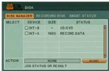
DISK DISK MANAGER RECRDING DISK SMART STATUS SELECT DEVICE SIZE STATUS INT-B - CD/DVD INT-A 160G RECORD DATA ACTION NONE START JOB STATUS OR RESULTDISK MANAGER
Disk Manager Tab
The Disk manager tab allows you to view connected hard drives/ CD/DVD writers, configure hard drive mirroring, and hard drive health.
Understanding the Status readings
The Status column indicates devices that are connected to the system, and the health of the hard drive.
• Damaged: The hard drive is unusable.
Formatting a new hard drive
You must format a new hard drive before it can be used for recording.
To format a new hard drive connected to the system:
- Install the new internal hard drive to the DVR.
- Under DEVICE, select the hard drive. The naming convention looks something like this: "INT-A: Unknown".
- In the ACTION field, click +/- and select Assign to Record.
- Click Start t o format the hard drive. After the formatting is complete, the hard drive shows up in the RECORDING DISK tab.
Mirroring (RAID 1)
The mirroring feature allows two hard drives to write duplicate data to onto each other. In the event that one hard drive fails, there will always be a back up hard drive with identical data.
To set up disk mirroring:
- Ensure you have two internal hard drives installed in the system.
- Under DEVICE, select the two hard drivers
Using the Main Menu
Record + Mirror
The Record+Mirror function allows you turn a hard drive that is assigned as a recording hard drive, into a mirroring hard drive.
- Ensure you have two internal hard drives installed in the system.
- Under DEVICE, select the hard drive you wish to set up for disk mirroring.
- In the ACTION field, click +/- and select MIRROR ON INT-A.
NOTE: The two hard drives should be identical brand/model/capacity.
- Click Start to format the hard drive. After the formatting is complete, one hard drive will be set up for mirroring, and the other for recording.
Initializing (formatting) a hard drive for backup
Before the system can detect an internal hard drive, it must be initialized.
To initialize a hard drive:
- Connect the internal hard drive to the system.
- Under DEVICE, select the drive you wish to initialize.
-
In the ACTION field, click +/- and select Initialize for backup.
-
In the ACTION field, click +/- and select Link Record Disk.
- Click Start t o begin the process.
Limitations of the Record Disk function:
- You must remove the original hard drive before installing the new hard drive from another system.
- The hard drive must be from the same DVR series.
Recording Disk
The Recording Disk tab lists the drives that are currently used for system recording.

text_image
DISK DISK MANAGER RECORDING DISK SMART STATUS NO SIZE RANGE DEVICE STATUS ACTION 154G / 159G INT-A STABLE REMOUS 01/27 - 02/25 2 3 4The Recording Disk menu displays the following:
- SIZE, RANGE: Displays the hard drive size, and the duration of recording.
• DEVICE: Displays the type of device connected to the system.
Using the Main Menu

NETWORK
Configure network and DDNS options.

text_image
NETWORK ETHERNET GENERAL EMAIL SMTP DONS CONFIG @ STATIC IP ○ DHCP IP ADDRESS 192 168 10 19 NETMARK 255 255 255 0 GATEWAY 192 168 10 1 PRI DNS SERVER 192 168 0 5 SEC DNS SERVER 210 220 163 82ETHERNET
The ethernet tab displays the current system IP, netmask, gateway and DNS server IP.
Configuring Network Type: STATIC vs DHCP
The system has the ability to operate in DHCP mode and Static IP mode. DHCP allows the router to assign an IP to the DVR. Static IP mode fixes the IP of the DVR. Fixing an IP of the DVR ensures that the IP will not change.
To change between Static IP and DHCP:
GENERAL
The general tab allows you to configure the system port number, and various security settings.
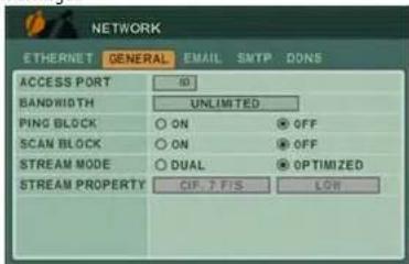
text_image
NETWORK ETHERNET GENERAL EMAIL SMTP DONS ACCESS PORT 10 BANDWIDTH UNLIMITED PING BLOCK ON OFF SCAN BLOCK ON OFF STREAM MODE DUAL OPTIMIZED STREAM PROPERTY CIF. T FIS LOWTo configure the GENERAL tab:
-
Configure the following:
-
ACCESS PORT: Enter the desired system port number (default port 80).
• BANDWIDTH: Select from UNLIMITED, 4,8,16,32,64,128,256,512 KBPS; 1,2,4,8 MB. - PING BLOCK: Select ON to prevent outside connections from pinging the DVR.
• SCAN BLOCK: Select ON to prevent outside connections from scanning the DVR. - STREAM MODE: Select from DUAL or OPTIMIZED. Select OPTIMIZED to allow the DVR's built-in algorithm to determine the
Using the Main Menu
The DVR can send out email notifications when a motion or alarm event occurs.

text_image
NETWORK ETHERNET GENERAL EMAIL SMTP DONG USE OFF DEFAULT SMTP SEND FREQUENCY EVENT IMMEDIATELY LOG 1 DAY RETRY COUNT NONE EMAIL SOURCE EVENT EDIT LOG ATTACH PICTURE ON CFF EMAIL ADDRESS ADDRESS 1
Event Edit i con
To use the Digimerge email server (recommended):
- Beside USE, select DEF AULT.
-
Configure the following:
-
EVENT: Select how frequent you want the system to send out email alerts. Note that the system only sends out a email notification if there is an event trigger (i.e. motion or alarm trigger).
-
Log : Select how long the system logs should be (select from 1 day or 1 week).
-
Log (Email Source): Select the Log checkbox if you want the system to email a system log.
- Attach Picture: Select ON for the system to attach an image in the email alerts.
-
Email Address: Enter up to 5 email addresses that will receive email notifications from the system.
-
Click ENTER to save your settings.

- Event Edit (I) click this icon to configure the type of alarm settings that will cause the system to send out email alerts.
To configure the EVENT EDIT (EMAIL) window:
-
Configure the following:
-
ALARM IN: Select the alarm in devices that will cause the system to send email notifications if an alarm is triggered.
- MOTION: Select the channels that will cause the system to send email notifications if motion is detected.
- SYSTEM: Select the events that will cause the system to send out email notifications. For a list of icons and what they mean, see
Using the Main Menu
What the SYSTEM icons mean:

- HDD DISK FAIL: A hard drive error occurred.

- RECORD SYSTEM FAIL: The system stopped recording.

- TEMPERATURE WARNING: The system is overheating.

- VOLTAGE WARNING: There was a surge in electrical output.

- LOW RTC BATTERY WARNING: The system's internal clock battery is low.

- EXTERNAL DEVICE EVENT: A USB device has been removed.

- NETWORK LINK DISCONNECT: The ethernet cable was unplugged.
To use a custom SMTP email server:
-
In the EMAIL tab, select SMTP.
-
Configure the following:
• Server: Enter the SMTP server name.
- Port: Enter the SMTP port number.
- Authentication: Select ON/OFF.
- User ID: Enter your SMTP user ID.
- Password: Enter your SMTP password.
- Send Test: Click the Start button to send out a test email to your SMTP email account.
- Click ENTER to save your settings.
Using the Main Menu
DDNS
IMPORTANT
Digimerge DDNS is the only DDNS service supported by Digimerge. Digimerge will not provide support for DYNDNS or any other DDNS services. Please contact your DDNS provider for support for other DDNS services.
Configure Digimerge DDNS settings.
NOTE: You must register for the FREE Digimerge DDNS service prior to configuring DDNS settings.
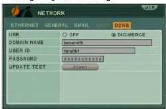
text_image
NETWORK ETHERNET GENERAL EMAIL INPUT DDNS USE OFF DIGMERGE DOMAIN NAME tomemith USER ID tommft PASSWORD ########### UPDATE TEST Start1To configure DDNS settings:
- Under USE, select DIGIMERGE.
- Under DOMAIN NAME, enter only the first portion of your DDNS domain from the confirmation email. For example, if your
re-enter your Digimerge DDNS information.
- Click ENTER to save your settings.
Connecting to your system
After you have port forwarded the required port, created a DDNS account, and enabled DDNS on your system, you must enter the DDNS URL into Internet Explorer to access your DVR.
The DDNS URL must include http://, the name of your DDNS URL, followed by a colon, then the port number of your DVR.
For example:

NOTE: If you change your default port number (port 80) to a different port, you still need to enter your port number after the DDNS address.
Entering DDNS information using the remote

DEVICE
Configure Alarm Out, Alarm Buzzer, and alarm input settings.
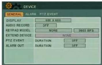
text_image
DEVICE GENERAL ALARM PTZ EVENT DISPLAY 800 X 600 AUDIO RECORD OFF KEYPAD MODEL NONE 9800 BPS EXTEND DEVICE NONE PTZ EVENT DURATION OFF ALARM OUT DURATION OFFGENERAL
The GENERAL tab allows you to configure Post Recording time, Audio recording, Key Tone (key "beeps"), and Key Sensitivity.
- Configure the following in the General tab:
• DISPLAY: Select the output resolution.
• AUDIO RECORD: Select ON or OFF to enable or disable audio recording.
- KEYPAD MODEL: Select the PTZ keyboard model and baud rate.
- EXTENDED DEVICE: Select the desired device
• PT7 EVENT- Select the duration of a PT7
ALARM
The ALARM tab allows you to configure the system Alarm Buzzer and Alarm Input type on each channel (i.e. N.O and N.C (normally open and normally closed) settings)).

text_image
DEVICE GENERAL ALARM PTZ EVENT INPUT 1 N.O. 2 N.O. 3 N.O. 4 N.O. USE INACTIVE CONTROL OUTPUT N.C. EVENT ON BUZZER ON EVENT ON-
Configure the following in the Alarm tab:
-
INPUT: Select the alarm type connected to the particular channel. Select from N.O or N.C (Normally Open, or Normally Closed).
- OUTPUT: Select N.O (Normally Open) or N.C (Normally Closed). Under INACTIVE, select the event type (Manual or Event).
- BUZZER: Select ON/OFF. Under INACTIVE, select the event type (Manual or Event).
-
CONTROL: Turn the OUTPUT/ BUZZER on or off. To enable the ON button, under INACTIVE select MANUAL.
-
Click ENTER to save your settings.
Using the Main Menu
- Click the EDIT EVENT icon[] beside OUTPUT/BUZZER to configure the actions that follow when an alarm output occurs / buzzer. The alarm output must be set to N.C or N.O before you can access the Edit Event window.

text_image
DEVICE GENERAL 2.000 PTE EVENT INPUT 1 NO 2 NO 3 NO 4 NO USE INACTIVE ON CONTROL OUTPUT NO EVENT Puzzler ON EVENT Edit Event icon-
Configure the following in the EVENT EDIT (ALARM OUT 1) Window:
-
ALARM IN: Select the other alarms that will also trigger when Alarm OUT 1/ BUZZER activates.
- MOTION: Select the cameras that will cause ALARM OUT 1/BUZZER to activate when motion is detected.
• VLOSS: Select the cameras that will cause ALARM OUT1/BUZZER to activate when video loss occurs in one of the cameras.
PTZ EVENT
The PTZ Event menu allows you to configure the PTZ camera to go to a pre-defined pre-set or tour setting when an event occurs. For example, if camera 1 detects movement, the PTZ camera (camera 2) will automatically pan towards the front door.

text_image
DEVICE GENERAL ALAR PTZ EVENT NO CHANNEL ACTIVE INACTIVE 01 01 NONE (00) NONE 000 02 01 NONE (00) NONE 000 03 01 NONE (00) NONE 000 04 01 NONE (00) NONE 000 05 01 NONE (00) NONE 000 06 01 NONE (00) NONE 000 07 01 NONE (00) NONE 000 08 01 NONE (00) NONE 000To configure the PTZ Event tab:
-
Configure the following:
-
CHANNEL: Select the channel number the PTZ camera is connected to.
• ACTIVE: This setting instructs what action the PTZ camera performs when an event occurs. Select from NONE, GOTO or TOUR. - In the number field, enter the GOTO or TOUR preset number. This number is programmed into the PTZ by the user.
• INACTIVE: This setting instructs what action the PTZ camera performs after an
Using the Main Menu
- EDIT EVENT [ ]: Click this icon to open the PTZ EVENT EDIT window. This allows you to configure the type of events that will trigger the PTZ camera.
-
Configure the following:
-
ALARM IN: Select the alarms that triggers the PTZ camera to move to a pre-defined location when the Alarm Input triggers.
-
MOTION: Select the cameras that triggers the PTZ camera to move to a pre-defined location when the cameras detect motion.
• VLOSS: Select the cameras that cause the PTZ camera to move to a pre-defined location when Video Loss occurs on the selected cameras. -
Click EN TER to save your settings.
Alarm recording will take priority over continuous recording, even if a camera is disabled in standard recording parameters.
Using the Main Menu

SYSTEM
Configure System settings.

text_image
SYSTEM GENERAL TIME ACCOUNT UPDATE INFO CONTROL ID 32 EVR NAME KEY TONE ON OFF PB DEINTERLACE ON OFF AUTO LOGOUT OFF SMART MONITOR ON OFF KEY SENSITIVITY 2GENERAL
To configure general system settings:
- Configure the following:
- CONTROL ID: This setting allows you to pair a DVR with a remote. For example, if you have several DVRs in the same room, and you want to control them with one remote, you can pair the remote to the DVR, so that the remote will only control that particular DVR.
To pair a remote to the DVR, enter a number from 00\~99. Click ENTER to save your settings.
On your remote control, press and hold the DVR ID button while pressing the number of the CONTROL ID. The Control ID number and the number you enter into your remote
- SMART MONITOR: Turn ON/OFF to show or hide the hard drive S.M.A.R.T status in the DISK menu.
- KEY SENSITIVITY: Press -/+ to increase or decrease the button sensitivity on the front panel of the system.
TIME
For more details, on setting the date and time, see "Setting the Time" on page 18.
ACCOUNT
Only the ADMIN can configure user authorities on the system.

text_image
SYSTEM GENERAL TIME ACCOUNT UPDATE INFO USER: NAME ADMIN ADMIN ACTIVATE ON OFF PRIVELICE DESCRIPTION : NETWORK SYSTEM P/R CHANNEL PASSWORD OLD NEW CONFIRMTo configure user and account settings:
- Select the ACCOUNT tab, and configure the following:
- USER/NAME: Click the -/+ button to configure the user type. You can change the default admin login name. Configure up to 5 users.
- ACTIVATE: Select ON/OFF to enable or
Using the Main Menu
UPDATE
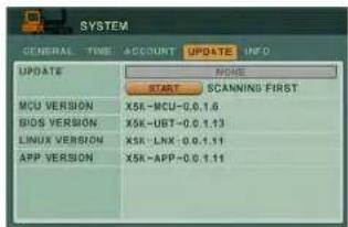
text_image
SYSTEM GENERAL TIME ACCOUNT UPDATE INFO UPDATE MCU VERSION X5R-MCU-0.1.6 BIOS VERSION X5R-UBT-0.1.13 LINUX VERSION X5R-LNX-0.1.11 APP VERSION X5R-APP-0.1.11Use the Update menu to upgrade system firmware.
NOTE: The system supports most major brands of USB flash drives with a capacity of 10 MB \~ 16 GB.
To upgrade firmware:
- Download the latest firmware update from the Digimerge website.
- Copy the firmware to a blank USB flash drive.
NOTE: Do not have any folders on the USB flash drive—just the firmware file.
- Connect the USB flash drive to the USB port on the front or back panel.
- Stop all recording on the system.
NOTE: You must stop all recording in order to perform the upgrade.
- Open the Main Menu and select .CVCTEM
INFO
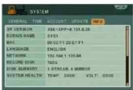
text_image
SYSTEM GENERAL TIME ACCOUNT UPDATE INFO SR VERBUN ASK-APP-8.131.6.28 DOMAIN NAME SYS1 MAC 00:02-F1 23:57-F1 LANGUAGE ENGLISH NETWORK 132.148 1.135.48 RECORD DISK 160G DISK SUMMARY 1 STREAM.0 MIRROR SYSTEM HEALTH TEMP GOOD VOLT GOOD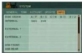
text_image
SYSTEM GENERAL TIME ACCOUNT UPDATE INFO DISK ORDER A/F B/G C/H D/I E/J INTERNAL 140C DVB EXTERNAL 1 EXTERNAL 2 USD FRONT USD REARView important system information:
- S/W VERSION: The current system firmware version.
• DOMAIN NAME: Your Digimerge DDNS domain name.
• MAC: The physical address of the DVR on your network.
• LANGUAGE: The current system language.
• NETWORK: The IP address of the system - RECORD DISK: HDD, size and space remaining.
- DISK SUMMARY: The status of the HDDs
Backup
BACKUP
ATTENTION: You must STOP ALL RECORDING on the system prior to backing up any video data to an external USB HDD or external USB CD/DVD-RW drive.
Backup critical video data on your system to a USB flash drive, external USB HDD, FTP server, or the CD/DVD-RW drive in the system (specified models only. Some models may not ship with a built-in CD/DVD-RW drive).
NOTE: The system supports most major brands of USB flash drives with a capacity of 10 MB - 4 GB. Most major brands of USB HDDs and CD/DVD-RW drives are supported.
Backing up to a USB Device or CD/DVD Burner
To backup recorded video:
- Connect a blank USB flash drive / external hard drive to the USB port on the front panel, or insert a blank CD/DVD into the CD/DVD drive.
- If using a USB drive, format the USB flash drive if you have not already done so.
- Press the BACKUP button on the front panel. Enter the system password if required.
- Under DEVICE, select the name of your USB device.
- Under CHANNEL, select the channels you wish to back up.
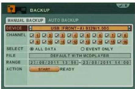
text_image
BACKUP MANUAL BACKUP AUTO BACKUP DEVICE USB (FRONT-A) 932M/1.00G CHANNEL ✓ 1 ✓ 2 ✓ 3 ✓ 4 ✓ 5 ✓ 6 ✓ 7 ✓ 8 ✓ 9 ✓ 10 ✓ 11 ✓ 12 ✓ 13 ✓ 14 ✓ 15 ✓ 16 SELECT ● ALL DATA ○ EVENT ONLY FILE DEFAULT WITH MCDPLAYER RANGE 23/08/2011 13:50 ~ 23/08/2011 14:00 ACTION START READYBackup
Backing up to an FTP Server
NOTE: Using the system locally, you can only configure the backup interval and test the connection for an existing FTP connection. To setup automatic backup to an FTP server, you must use the CMS-DH software. For instructions, see "Configure Backup to FTP Server" on page 83.
To test an existing FTP connection:
- Press the BA CKUP button on the front panel. Enter the system password if required.
- Select A UTO BACKUP.
- Under DEVICE, click SE TUP.
- Under TEST, click ST ART to test the FTP connection. Good is displayed if FTP connection is working. If an error is displayed, check your FTP settings and ensure that the system can be accessed through CMS-DH.
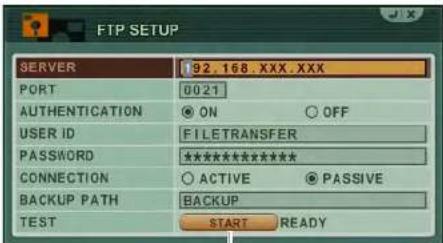
text_image
FTP SETUP SERVER 192.168.XXX.XXX PORT 0021 AUTHENTICATION ON OFF USER ID FILETRANSFER PASSWORD ********** CONNECTION ACTIVE PASSIVE BACKUP PATH BACKUP TEST START READYClick to test FTP connection
To configure a schedule for FTP backup:
By default, the system will backup all video data to FTP in 24-hour intervals. You can configure a daily schedule to only backup data from a specified time range.
NOTE: FTP connection must be active before scheduling FTP backup.
- Press the BACKUP button on the front panel. Enter the system password if required.
- Select A UTO BACKUP.
- Under RANGE, select ENABLE and configure the start time and end time (24-hour clock) for daily backups
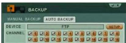
text_image
BACKUP MANUAL BACKUP AUTO BACKUP DEVICE FTP SETUP CHANNEL 1 2 3 4 5 6 7 8 9 10 11 12 13 14 15 16Backup
Viewing Backup Video
Along with copying the files, the system adds a Backup Video Player (McdPlayer) to the USB flash drive, external HDD, and external USB CD/DVD-RW drive. Use the Video Player to view the backed up video files on your PC.
NOTE: You can also view the files using the browser-based remote surveillance software.
To view backup video:
-
Connect the USB flash drive or external USB HDD with the backed up video data to your PC; or insert the CD/DVD-R/W disc into your PC's CD/DVD-RW drive.
-
McdPlayer should launch automatically. If Autorun does not start, search the drive/disc and double-click mcdplayer.exe to launch the Backup Video Player. McdPlayer launches and begins to load your backed up video.
NOTE: If the drive contains more than one video file, first select the file and click OK.
- When the purple progress bar has loaded, you can begin to playback the video.
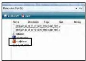
text_image
Modulplay Name: Date: 01/06/2009 File Size: 0000.0000.0000.0000.0000.0000.0000.0000.0000.0000.0000.0000.0000.0000.0000.0000.0000.0000.0000.0000.0000.
natural_image
Interior view of a room with furniture and a window (no visible text or symbols)NOTE: The "C" button stands for Capture. The "D" button
Backup
Using MCD Player
MCD Player is a small application that the system places on your USB flash drive when you backup critical video.
To use MCD Player:
- Connect the USB flash drive or external HDD with the back ed up video data to your PC; or insert the CD/DVD-R/W disc into your PC's CD/DVD-RW drive.
- Double-click mcdplayer.exe to launch the Backup Video Player. The Video Player launches and begins to load your backed up video.
NOTE: If the drive contains more than one video file, first select the file and click OK.

natural_image
Interior scene with people interacting near a display table and animal model (no visible text or symbols)McdPlayer main window (image simulated)
- When the purple progress bar has loaded, you can begin to playback the video.
-
Use the playback buttons at the top of the main screen to control playback.
-
Reverse playback -4X
- ⚡Forward step (frame-by-frame)
- Reverse playback -2X
- Forward play 1X
- Reverse playback -1X
- Forward play 2X
- Backward step (frame-by-frame)
- Forward play 4x
E. To check full, unless click the . . . . . . . . . . . . . . . . . . . . . . . . . . . . . . . . . . . . . . . . .
Backup
CMS-DH CENTRAL MANAGEMENT SOFTWARE
CMS-DH is a central management software that allows you to view and manage up to 300 DH230 series DVRs.

text_image
Screenshot of a video editing software interface showing multiple video frames with Chinese text overlays and UI elements.System Requirements
Your system must meet the system requirements below:
Minimum system requirements
- Windows XP SP 1
- Pentium 4, 2.4Ghz
- 512 MB RAM
• 64 MB AGP video card - 1024 x 768 monitor resolution
Recommended system requirements
- Windows XP SP 1
- Pentium 4, 3.0 Ghz
- 1GB RAM
• 256 MB, PCI-E video card
• 1600 x 1200 monitor resolution
- - - -
CMS-DH Central Management Software
Installing CMS-DH
To install CMS-DH:
- Locate the CMS-DH software included with the software CD.
- Double-click the CMS-DH setup file.
NOTE: You may receive installation warnings. This is normal. Accept the security warnings to continue.
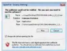
- Follow the on-screen instructions to install the software.

text_image
CMS-01.3.2 Setup Instruction System This will install the entire single CMS-01 in your computer. Select which Windows or Windows installed. Select components to install: □ Install software □ IP Control Setup □ IP Server Storage □ IP Server Software □ Desktop Provider □ Desktop Provider □ IP TIME (TIME) (PROGRAM) Space required: 41.8PS Cancel Install Default Options Next > CMS-01.3.2 Setup Instruction System Create a directory by insert in the Configuration folder Name: CMS-01.3.2 Browse... Space required: 41.8PS Space available: 21,702 Cancel Install Default Options Next Cancel- Click Ye s to restart the computer when prompted.
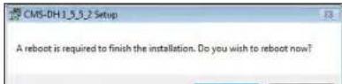
Starting CMS-DH
To start CMS-DH:
- Double-click the CMS-DH icon [↑] on the desktop.

Adding a DVR from the local area network (LAN)
Once you open CMS-DH, you can add a DVR.
To add a DVR to CMS-DH:
- Click Devic e.
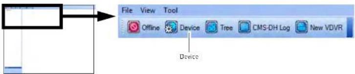
text_image
File View Tool Offline Device Tree CMS-DH Log New VDVR Device- Click Scan to locate connected DVRs on the network.
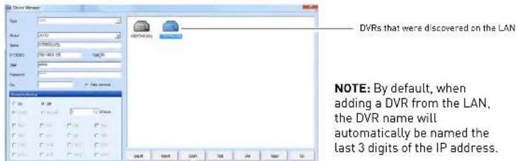
text_image
DVRs that were discovered on the LAN NOTE: By default, when adding a DVR from the LAN, the DVR name will automatically be named the last 3 digits of the IP address.CMS-DH Central Management Software
- Click on the DVR you wish to add to CMS-DH, and then click Apply→OK.
• The DVR appears on the left panel.
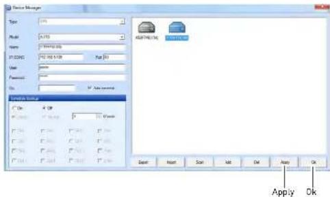
text_image
Device Manager Type: 100% Model: A153 Name: C:\WINDOWS\XXX P:D:\XXX\XXX\XXX\XXX\XXX\XXX\XXX\XXX\XXX\XXX\XXX\XXX\XXX\XXX\XXX\XXX\XXX\XXX\XXX\XXX\XXX\XXX\XXX\XXX\XXX\XXX\XXX\XXX\XXX\XXX\XXX\XXX\XXX\XXX\XXX\XXX\XXX\XXX\XXX\XXX\XXX\XXX\XXX\XXX\XXX\XXX\XXX\XXX\XXX\XXX\XXX USEUM NAME C:\XX C:\XXXX\XXX C:\XXXX\XXX C:\XXXX\XXX C:\XXXX\XXX C:\XXXX\XXX C:\XXXX\XXX C:\XXXX\XXX C:\XXXX\XXX C:\XXXX\XXX C:\XXXX\XXX C:\XXXX\XXX C:\XXXX\XXX C:\XXXX\XXX C:\XXXX\XXX C:\XXXX\XXX C:\XXXX\XXX C:\XXXX\XXX C:\FLASH\Sigma C:\FLASH\Sigma C:\FLASH\Sigma C:\FLASH\Sigma C:\FLASH\Sigma C:\FLASH\Sigma C:\FLASH\Sigma C:\FLASH\Sigma C:\FLASH\Sigma C:\FLASH\Sigma C:\FLASH\Sigma C:\FLASH\Sigma C:\FLASH\Sigma C:\FLASH\Sigma C:\FLASH\Sigma C:\FLASH\Sigma C:\FLASH\Sigma C:\Flash\Sigma C:\Flash\Sigma C:\Flash\Sigma C:\Flash\Sigma C:\Flash\Sigma C:\Flash\Sigma C:\Flash\Sigma C:\Flash\Sigma C:\Flash\Sigma C:\Flash\Sigma C:\Flash\Sigma C:\Flash\Sigma C:\Flash\Sigma C:\Flash\Sigma C:\Flash\Sigma C:\Flash\Sigma C:\Flash\Sigma D:\Flash\Sigma D:\Flash\Sigma D:\Flash\Sigma D:\Flash\Sigma D:\Flash\Sigma D:\Flash\Sigma D:\Flash\Sigma D:\Flash\Sigma D:\Flash\Sigma D:\Flash\Sigma D:\Flash\Sigma D:\Flash\Sigma D:\Flash\Sigma D:\Flash\Sigma D:\Flash\Sigma D:\Flash\Sigma D:\Flash\SSigma D:\Flash\SSigma D:\Flash\SSigma D:\Flash\SSigma D:\Flash\SSigma D:\Flash\SSigma D:\Flash\SSigma D:\Flash\SSigma D:\Flash\SSigma D:\Flash\SSigma D:\Flash\SSigma D:\Flash\SSigma D:\Flash\SSigma D:\Flash\SSigma D:\Flash\SSigma D:\Flash\SSigma D:\Flash\SSigma D:\FFS\nF\nA\nB\nA\nB\nA\nA\nA\nA\nA\nA\nA\nA\nA\nA\nA\nA\nA\nA\nA\nA\nA\nA\nA\nA\nA\nA\nA\nA\nA\nA\nA\nA\nA\nA\nA\nA\nA\nA\nA\nA\nA\nA\nA\nA\nA\nA\nA\nA\nA\nA\nA\nA\nA\nA\n-
If you have changed the default password of the DVR, you must select the DVR from the list, then manually re-enter the new password in the Password field, and then click Apply and then OK.
- Click on the DVR you want to connect, and click the Offline button.

text_image
2. Click the Offline button File V1 Tool Offline Device Tree CMS-DH Log New VDVR Group XSET/TESTOR 1. Select the DVR you want to connect.Adding a DVR using a DDNS address
If you have DVR systems that have DDNS set up, you can add them to CMS-DH.
Prerequisites
- Create a DDNS account.
- Enter the DDNS information into the DVR locally.
- Port forward the required port (default, port 80) to the router.
To add a DVR using a DDNS address:
- Make sure the DVRs have been disconnected from CMS-DH. Click De vice.

text_image
File View Tool Offline Device Tree CMS-DH Log New VDVR Device- In the Device manager window, click Add.

text_image
AddCMS-DH Central Management Software
-
Enter the following into the blank fields:
-
Name: Enter the DVR name of your choice.
- IP/DDNS: Enter the DVR's DDNS address (for example tomsmith.digimerge.net)
- Port: Enter the DVR's port number (by default, port 80)
- User:Enter the DVR's user name (by default, admin)
- Password:Enter the DVR's password (by default, 000000)
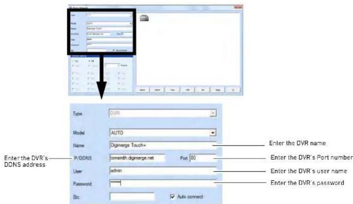
text_image
Enter the DVR's DDNS address Type: DVR Model: AUTO Name: Digimerge Touch+ P/DDNS: comsmith.digimerge.net Port 00 User: admin Password: ***** Btc: Auto connect Enter the DVR name. Enter the DVR's Port number Enter the DVR's user name Enter the DVR's password- Click A pply→Ok.

CMS-DH Central Management Software
- Click the Offline button to connect to the DVR. Double-click the DVR icon to begin viewing.
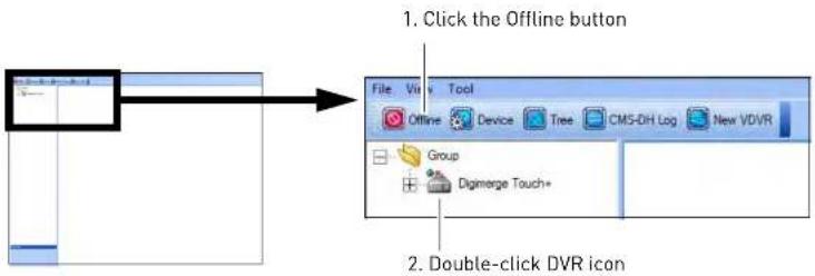
text_image
1. Click the Offline button File Vis Tool Offline Device Tree CMS-DH Log New VDVR Group Digimerge Touch+ 2. Double-click DVR iconFinal Result

text_image
Screenshot of a surveillance camera interface showing three video feeds with bounding boxes and vehicle images, including timestamps and camera settings.Adding a Virtual DVR
A virtual DVR allows you to add video sources from multiple DVRs, into one main window.
Example
In the example below, multiple video sources from two DVRs are grouped into the Virtual DVR.
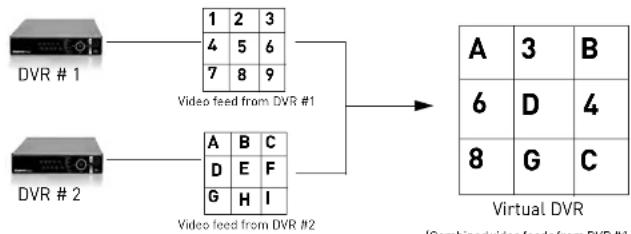
flowchart
graph LR
    A["DVR #1"] --> B["1 2 3"]
    A --> C["4 5 6"]
    A --> D["7 8 9"]
    E["DVR #2"] --> F["A B C"]
    E --> G["D E F"]
    E --> H["G H I"]
    B --> I["Video feed from DVR #1"]
    C --> J["Video feed from DVR #2"]
    F --> K["Virtual DVR"]
    G --> K
    H --> K
    I --> L["A 3 B"]
    I --> M["6 D 4"]
    I --> N["8 G C"]
    K --> O["I/Combined/video feeds from DVR #1"]
Prerequisites
- Ensure the DVRs are online, and connected to CMS-DH.
To add a Virtual DVR:
- Click the Ne w VDVR button


New VDVR
CMS-DH Central Management Software
- Double-click the virtual DVR icon in the tree menu on the left.
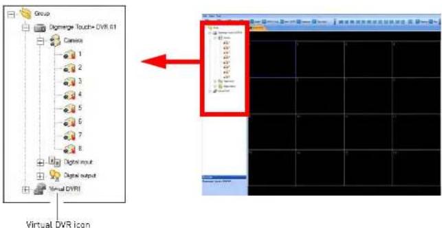
text_image
Group Digmerge Touch+ DVR 61 Camera 1 2 3 4 5 6 7 8 Digital input Digital output Virtual DVRI Virtual DVR Icon- Click the + symbol to expand the DVR menu tree.
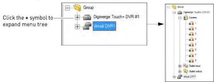
text_image
Click the + symbol to expand menu tree Group Digimerge Touch+ DVR #1 Virtual DVR1 Group Digimerge Touch+ DVR #1 Camera 1 2 3 4 5 6 7 8 Digital input Digital output Virtual DVR1- Drag the desired camera into the Virtual DVR window.
CMS-DH Central Management Software
Creating New Group Folders & Sub folders
Creating group folders and sub-folders helps you organize multiple DVRs. For example, you can create a new folder for each different DVR.
To create group folders:
- Right-click on the Group folder, then click New Group.

text_image
CMS-DR File Edit View Tool Online Tree E-Map Love New VDVR New E-Map New group New sub group Rename Open All Remove CMS DR File Edit View Tool Online Tree E-Map Love Health Group E-Map 1 Touch DVTh Camera Alarm input Alarm output Group New Group folder- Drag the desired DVR into the new folder.
To create a sub-group:
- Right-click on the Group folder, then click New sub group.
CMS-DH Central Management Software
Configuring General System Settings
To configure general system settings:
- Open CMS-DH to access the Login window and then click Setup [Or, click File→ Setup once you are logged in to CMS DH]

text_image
Login User ID: admin Password: Setup Setup CMS DH OK Setup User Password: New Password: Colder Password: Data Data Transfer Web Table Web Link Web Link Web Link Web Link Web Link Web Link Web Link Web Link Web Link Web Link Web Link Web Link Web Link Web Link Web Link Web Link Web Link Web Link Web Link Web Link Web Link Web Link Web Link Web Link Web Link Web Link Web Link Web Link Web Link Web Link Web Link Web Link Web Link Web Link-
Configure the following in the Setup menu:
-
OSD Setup: Configure the on-screen display items that you want to appear in the channel (i.e. camera name, time, frame rate etc.).
- Password: Change the CMS-DH login name and password. Enter your desired ID (user name) and password, and then click OK to save your settings.
- Miscellaneous: Select the items you wish to enable:
- Check Watermark: Checks the system screenshots to ensure that they have not been tampered.
- Keep Opened Window: Automatically re-opens the windows that were closed after you restart the program.
- E-Map Link Event: When selected, the E-map will open pop-up windows when an event occurs (setup required)
Adding Users
You can add multiple users to CMS-DH, specifying the DVR menus that each user is allowed to access.
To add a new user:
- Log in to CMS-DH.
- Click Fil e→CMS-DH Account.
- Enter the following:
• ID: Enter the desired user name.
- Password: Enter the desired user password.
- Confirm Password: Re-enter the user password.

text_image
User Details ID Password Click Password User DVD1 List Check all Digimerge Touch+ DVD #1 Select the DVR the user will have access to Add OK Add OKRecording Video to the hard drive
CMS-DH allows you to record video to your local hard drive. The amount of video that you can record depends on the size of your computer's hard drive.
To record video:
- During live view, click the Rec button ( ). The Rec button turns red.
NOTE: If you want to capture a single channel of video, double-click the channel to view the channel in full screen mode, then click the Rec button.
NOTE: If you want to capture all channels, ensure that you are viewing the DVR in split screen mode, and then click the Rec button.
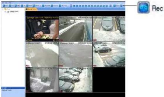
- Click the Rec but ton ( again to stop recording.
Playing back recorded video
The video is saved as a proprietary file that is playable only by CMS-DH.
To play back previously recorded video files:
- From the main window, click Fil e→File Playback.
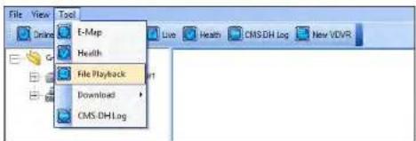
text_image
File View Tool E-Map Health File Playback Download CMS.DH.Log- Click the Open button.
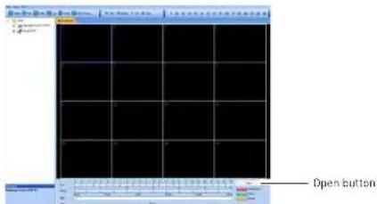
text_image
Open button- Select the desired file you wish to play and click Open.
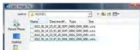
CMS-DH Central Management Software
Remote Search
Remote search allows you to search for archived video on the DVR.
Prerequisite
- Ensure you are connected to the DVR that you wish to search from.
To search for video:
- Right-click on the DVR that you wish to search video from, then click Remote Search.
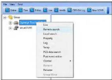
text_image
File View Tools Online Time Review New Search PDF/DB Log New VCR Group Save Text Local Live Remote search Local search Property Log Swap PUB data search Post query action Control Amount Resume Group Move- To search for the video:
a. Click to select the desired month.
b. Select the date of the video.
c. Select the hour.
d. Select the minute.

text_image
A 2011/1 Sun Mir - Sun Wed Thu, Fri, 3:50 Pou CCMS-DH Central Management Software
Video Playback Controls
Once the video begins to play, use the video controls to manipulate video playback.
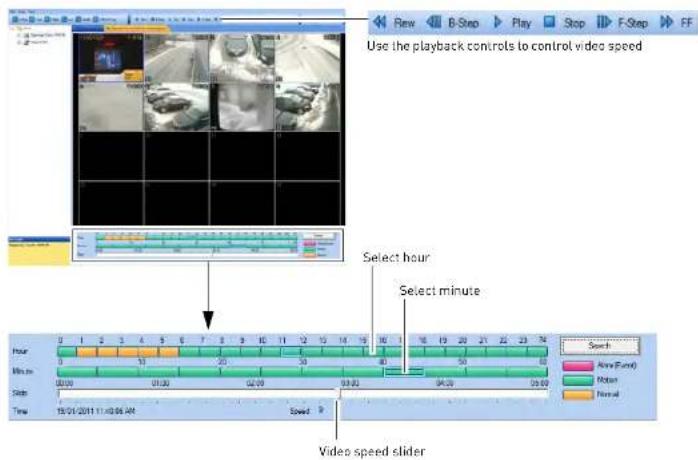
text_image
Use the playback controls to control video speed Select hour Select minute Video speed sliderLocal Search
Local search allows you to search for video stored locally on the computer hard drive.
Prerequisite
Ensure you are connected to the DVD that you wish to search from
- To search for the video:
a. Click to select the desired month.
b. Select the date of the video.
c. Select the hour
d. Select the minute
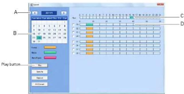
text_image
Start 2019/1 Play Info Top Word This Test Time A B Play button Play Button C D- Click the Play button to begin watching the video.
Saving Video Files
You can save the proprietary video files to your local hard drive from the Search menu. The video file ends in a .cms extension, and requires CMS-DH for playback.
To save video files from the search menu:
Converting video files to AVI
Converting proprietary .CMS video files to AVI allows you to play the video on a computer that does not have the CMS-DH software.
Prerequisite
- Make sure that you are in the Local Search menu (Right-click on the DVR, and click Local Search)
To convert video files to .AVI:
- Select the month, date, and time of the video.
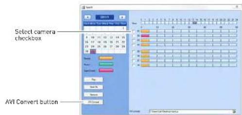
text_image
Select camera checkbox AVI Convert button- Select the checkbox beside the camera you wish to back up video from.
- Click the browse button ( ) and select the file output directory.
- Click the AV I Convert button. • CMS-DH converts the file, and stores it in the output directory.
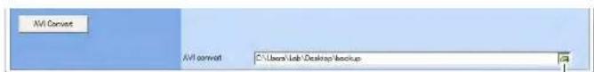
text_image
AVI Convert AVI convert C:\Users\Job\Desktop\backupCMS-DH Central Management Software
Schedule Recording
To enable/disable schedule recording:
- Right-click on the DVR you wish to configure and then click Contr ol→Schedule→Start / Stop
- Click Start to enable schedule recording. Click Stop to stop schedule recording.

text_image
Group Visual DVP1 Display Tools - DVM34 Line Remove search Local search Property Lng Setup POS data search Fast event action Control Record Schedule Start Stop Group MoveSchedule Backup to Local Hard Drive
You can schedule regular backup of video to your local hard drive. The schedule can be configured to back up 24 hours of video, or during a specified time only.
Prerequisite
- 3GB of hard drive space (backup will not function if there is less than 3GB)
• DVRs must be in offline mode
To configure Schedule Backup settings:
-
Click the DVR that you wish to configure.
-
Select On to enable schedule backup.
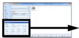

text_image
Schedule Backup On Off Daily Hourly 4 O'clock Ch1 Ch2 Ch3 Ch4 Ch5 Ch6 Ch7 Ch8 Ch6 Ch10 Ch11 Ch12 Ch13 Ch14 Ch15 Ch16Select channels you wish to back up
- Select Dail y to back up 24 hours of video to your hard drive. Go to step 6.
- Select Hourly to back up every hour of video to your hard drive. Go to step 5.
- In the Minute drop-down menu, enter how many minutes the system should wait before recording. For example, if you enter 10 minutes, the system will backup video footage from 8:10 a.m to 9:10 a.m.
- In the Hour drop-down menu, enter the time you wish to begin backup. For example, if you enter 5:00pm (05:00hr), the backup will start at 5:00pm, and end at 4:49am (the next day). Enter the hourly time in 24-hour format.
- Select the channels that you wish to enable schedule backup.

text_image
Schedule Backup On Off Daily Hourly 4 0'clockCMS-DH Central Management Software
Configure Backup to FTP Server
You can schedule regular backup of video to an FTP server. The schedule can be configured to backup 24 hours of video, or during a specified time only.
NOTE: To schedule a backup interval other than 24 hours, follow the instructions below first to set up your FTP connection. Then, see "Backing up to an FTP Server" on page 59.
Prerequisite
Ensure you are connected to the DVR you wish to schedule backup for.
FTP server URL or IP address, user ID, and password.
To configure backup to FTP:
-
Right-click the DVR you wish to configure and click Setup.
-
Select Sys tem→FTP Backup.
-
Configure the following:
- Server: Enter the URL or IP address for your FTP server on the left. Enter the port number on the right.
NOTE: Do not include the ftp://prefix.
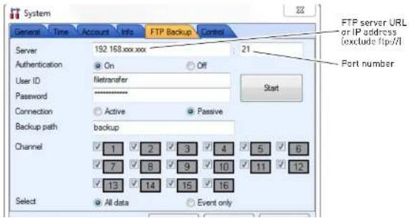
text_image
System General Time Account Info FTP Backup Control Server 192.168.xxx.xx 21 Authentication On Off User ID filetransfer Password ******** Connection Active Passive Backup path backup Channel 1 2 3 4 5 6 7 8 9 10 11 12 13 14 15 16 Select All data Event only FTP server URL or IP address (exclude ftp/II) Port number- Click Start to begin FTP connection.
NOTE: To confirm that the FTP connection has been made successfully, you must test the FTP connection using the local menus on the DVR. See "Backing up to an FTP Server" on page 59.
- Click Ok→Appl y.
The DVR begins FTP backup immediately. The DVR will backup data starting when the connection is established; it does not backup any data from the past 24 hours.
Taking Screen Captures
You can capture screen shots as JPEG or Bitmap images (JPG or BMP).
To take a screen capture:
- During live view, click Cap ture


text_image
Capture Click the Print button to print the image to a printer.- Click the Save As button. Enter the desired picture name, and select the desired save directory, and then click Save.
NOTE: To take a screen capture of a full-screen, double-click the desired channel, then click
CMS-DH Central Management Software
Viewing File Download Status
To check the download status of your video files:
- Connect to the DVR you wish to check the video status on.
- Click on To ols→Download→Status.
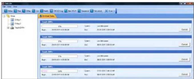
text_image
Torch EMFs 1% Begin: 20/01/2011 14:00:54 Current: Low Web space Begin: 20/01/2011 14:00:54 End: 20/01/2011 14:00:54 Control Torch EMFs 1% Begin: 20/01/2011 14:00:54 Current: Low Web space Begin: 20/01/2011 14:00:54 End: 20/01/2011 14:00:54 Control Torch EMFs 1% Begin: 20/01-2011 14:00:54 Current: Low Web space Begin: 20/01-2011 14:00:54 End: 20/01-2011 14:00:54 Control Torch EMFs 1% Begin: 20/01-2011 14:00:54 Current: Low Web space Begin: 20/01-2011 14:00:54 End: 20/01-2011 14:00:54 Control- To cancel the download, click Ca ncel.
Changing viewing modes
To change the viewing modes of CMS-DH:
- Log in to CMS-DH, and connect to a DVR.
- Click ( ) to change the viewing mode (single-channel, quad-channel etc).

text_image
Click to change viewing modesSequencing
If you monitor multiple DVRs, you can have each tab change continuously. This process is called sequencing. You can perform sequencing as long as you have two or more DVRs. Virtual DVR's work with sequencing as well.
Prerequisite
- Log in to two or more DVRs
To start a sequence:

text_image
• Click the Sequence button (# Sequence File View Tool Online Tree E-Map Live Health CMS-DH Log New VDVR Sequence Tab unlock Close Group Digmerge Touch+ DVR #1 New VDVR1 The two DVR tabs will continually switch between each otherNOTE: To change the sequence time, click File→Setup. Under "Miscellaneous", enter the desired sequence time in seconds, and click Ok.
CMS-DH Central Management Software
E-Map
The E-Map feature allows you to visually map your cameras over a Jpeg image.
Example

text_image
File Edit View Tool Online Tree E-Map Live Health CMS-DH Log New XVVR Sequence Tab unlock Close Zoom Group Dipmerge Touch+ DVR #1 Camera 1 2 3 4 5 6 7 8 Digital input Digital input Visual DVR1 Camera E-Map 1 Camera list From the camera list, you can drag the camera icon over the Jpeg image Jpeg image of a house blueprintPrerequisite
- Ensure the DVRs are online.
CMS-DH Central Management Software
- Click File→Background. Locate the file you wish to import, and then click Open.

text_image
CAD-CVI File Edit View Tool Online Setup CMS-CVI Account E-Map Setup Background Exit C:\Map Live Yeels CMS-DVI Log New VDIFT Source C:\Map 1- Drag the desired cameras from the camera list, over the image.
TIP: You can also drag the DVR icon and E-MAP icon over the image.
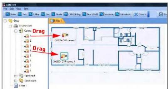
text_image
DMG-04 File Edit View Tools Edit View Insert Help View Insert New (N) Structure Settings Group DM2000+ DVM1 Camera Drag DM2000+ DVM1 camera Drag DM2000+ DVM1 camera 0 Right Input Digital output Left PathTip:
To rotate the camera, right-click on the
camera, and click Rotate.
Click the desired turning position to rotate the

CMS-DH Central Management Software
Viewing video on E-Map
Once you have mapped your cameras on E-Map, you can view, and search channels from the E-Map directly.
To view live video on E-Map:
- Double-click on the desired camera icon to open live view.
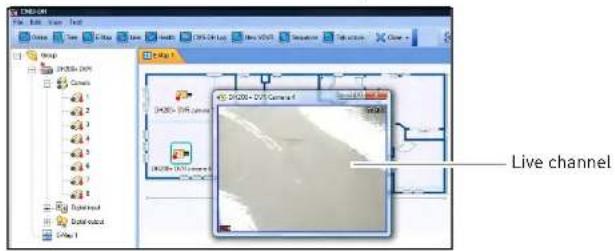
text_image
Live channelConfiguring E-Map camera settings
To configure E-Map camera settings:
-
Right-click on the camera you wish to configure.
-
Configure the following:
• Description Edit: Edit the camera name on the E-Map.
- Remote Search: Opens the video search menu
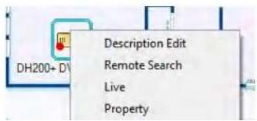
text_image
DH200+ D Description Edit Remote Search Live PropertyCMS-DH Central Management Software
Zooming into the E-Map
- To zoom into the E-Map, click the Zoom In / Zoom Out buttons (Zoom In Zoom Out).
To zoom into the E-Map, click the Zoom In / Zoom Out buttons (Zoom In Zoom Out

text_image
Zoom In/ Zoom OutRemoving camera icon in the E-Map
- Select the camera icon in the e-map, and click the Remove Item button [ Remove Item ).

flowchart
graph TD
    A["Start"] --> B{Check}
    B -->|Yes| C["Process Step 1"]
    B -->|No| D["End"]
Remove Item
Adding Multiple E-Maps
To add multiple E-Maps:
• Right-click the Group folder, and click New E-Map.


CMS-DH Central Management Software
Viewing DVR Health
To view the status of the DVR:
- Select the DVR on the menu tree on the left.
- Click the Health button | Health
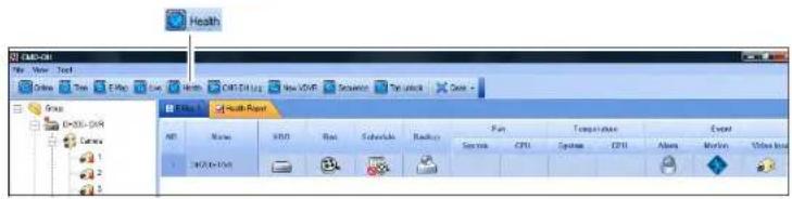
text_image
Health Health Report File Edit View Insert Tools Help Live Search CMS Click Log New PDFS Sequence Text Unlock Date - Name XWD Run Schedule Backup Fan Temperature Excel System CPU System CPU Access Motion Video Info HKEYLOG 1 2 3 4 5 6 7 8 9 10 11 12 13 14 15 16 17 18 19 20 21 22 23 24 25 26 27 28 29 30 31 32 33 34 35 36 37 38 39 40 41 42 43 44 45 46 47 48 49 50 51 52 53 54 55 56 57 58 59 60 61 62 63 64 65 66 67 68 69 70 71 72 73 74 75 76 77 78 79 80 System CPU System CPU Access Motion Video InfoClosing windows
To close open tabs:
- Click the Close button, and select Close or Close All.
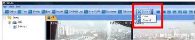
text_image
CMS-DH View Tool Online Tree E-Map Line Health CMS-DH Log New XYZB Sequence Tab units Group XK E-Map 1 Close Close offLocking Windows
CMS-DH Central Management Software
DVR Log
The DVR log allows you to check events that occurred in the DVR, such as hard drive malfunction, video loss, motion detection, and alarm settings.
To access the DVR log:
- Connect to the DVR that you wish to view the log from.
- Right-click on the DVR, and click Log.
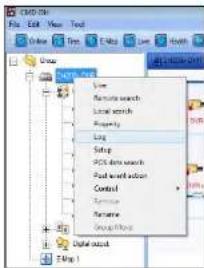
text_image
CMD-01 File Edit View Tools Help Add Search Save Save Find search Local search Property Log Setup POSTS test search Food web attack Control Transporter Formative Group Object Data source Figure 13. Configure the following:
- Begin & End: Specify the start and end date and time.
- Query: Select the event type you wish to search for
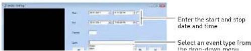
text_image
Enter the start and stop date and time Select an event type from the drop-down menuCMS-DH System Log
The CMS-DH log allows you to view video events that occurred in the system (i.e motion and camera loss events).
Prerequisite:
- Ensure the DVR(s) are online and connected to CMS-DH
To view the system log:
- Click the CMS-DH Log button ( )


text_image
CMS-DH File Edit View Tools Online Free E-Map Live Health CMS-PH Log New VD/Fr Sequence Tab unlock Close Group E-Map 1 Status DHPa Map 1 CMS-DH Log button-
Configure the following settings:
-
Begin: Enter the Month, Date, Year, and time you wish to begin to search the log.
• End: Enter the Month, Date, Year, and time you wish the log search to stop. - Channel: Enter the channel number you wish to search.

text_image
Playback screen Begin / End End Begin / End Channel Playback controlsCMS-DH Central Management Software
PTZ
To activate the PTZ control, click the PTZ button |

NOTE: You must select the channel that has a PTZ camera before using PTZ controls.
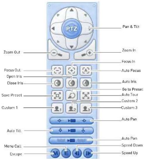
text_image
PTZ Pan & Tilt Zoom Out Focus Out Open Iris Close Iris Save Preset Custom 1 Auto Pan Auto Tilt Menu Call Escape Zoom In Focus In Auto Focus Auto Iris Go to Preset Auto Tour Custom 2 Custom 3 Auto Pan Speed Down Speed UpCMS-DH Central Management Software
System Setup
To access the full system setup menu:
- Right-click on the DVR you wish to configure.

text_image
C#D300 File View Tools Online Tree Edit Live Real C#D300 Log Group C#D300 Live Rename search Local search Proposty Log Setup POST based search Post user action Control Remove Panama Group Mode Setup Digital Digital input E-mail 1- Click Setup from the sub-menu to access the full Setup menu.

text_image
Setup Camera Camera Motion Motion Alum Solutions Balance SystemsCMS-DH Central Management Software
Upgrading the firmware remotely
Prerequisite
- Ensure the DVRs are online
- Download the firmware from www.digimerge.com, and extract the firmware file
To upgrade the DVR firmware using CMS-DH:
- Right-click on the DVR that you wish to upgrade the firmware.
- Click on Contr ol→DVR Setup→Update.
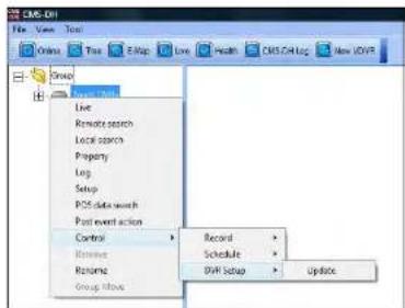
text_image
CMS-DVI File View Tools Online Tools Help Live Health CMS-DVI Log New OVP Group Control Record Schedule DVI Setup Update Live Remote search Local search Property Log Setup POS data search Post event action Control Review Rename Group History- Under Image File, click the browse button ( ). Locate the firmware file and then click Open.
NOTE: The firmware file ends in a .IMG extension.
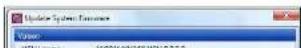
Configuring Post Event Action Tab
The Post Event Action tab allows your system to alert you when an alarm event triggers the DVR. For example, when the system detects motion from an input device, the computer speakers plays a sound to alert you. Or, you can have the CMS-DH software alert you with a pop-up window when motion is detected.
Setting up Post Event Actions on a NO/NC Device
Prerequisites (If setting up NO/NC Devices)
- Connect the input device into the alarm block in the rear panel of the DVR.
- Ensure you have the correct settings for the device (N/O, N/C), and that you have correctly configured the settings in the DVR menu.
- Ensure the DVRs are online.
To configure the Post Event Action tab:
- Expand the menu tree under the desired DVR that you wish to configure.
- Under Alarm Input, right-click the number block that your device is connected into.
- Click Po st Event Action.
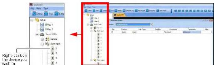
text_image
Right-click on the device you wish toCMS-DH Central Management Software
- Parameter: Select the desired alert sound you want the computer to play.

text_image
Past Event Action Events Alarm Input On No Device Sub Type Sub No. Command Parameter After 01 System Sound 1 Play Sound channel now 0 Click here to configure the Command and Parameter settings- Click Apply and then OK to save your settings.
- Under Alarm Output, right-click the light bulb icon, and click Contr ol.
- Click Alarm Output On or Alarm Output Off. This depends on your device type (N/O or N/C).
- Click A pply and then OK to save your settings.

text_image
Touch Cliffs+ Camera Nominal 1 2 3 4 5 6 7 8 Nominal Control False Alarm Output On Alarm Output OffWhen an alarm is triggered, the system will play a sound on the computer.
Configuring Alarm Output
CMS-DH Central Management Software
Setting message pop-up notifications
You can configure CMS-DH to produce message pop-up windows when an event occurs.
To configure CMS-DH to produce message pop-up events:
- Expand the menu tree under the desired DVR that you wish to configure.
- Right-click on the camera you wish to set alerts for, and click Post E vent Action.
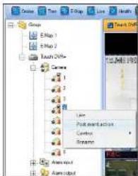
text_image
Groups E-Map 1 E-Map 2 Touch OVM+ Camera 1 2 3 4 5 6 7 8 9 10 11 12 13 14 15 16 17 18 19 20 21 22 23 24 25 26 27 28 29 30 31 32 33 34 35 36 37 38 39 40 41 42 43 44 45 46 47 48 49 50 51 52 53 54 55 56 57 58 59 60 61 62 63 64 65 66 67 68 69 70 71 72 73 74 75 76 77 78 79 80 81 82 83 84 85 86 87 88 89 90 91 92 93 94 95 96 97 98 99 100- In the Events drop-down menu, select the type of event that will trigger CMS-DH to produce a pop-up window when an event is detected.
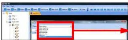
text_image
Screenshot of a software interface showing a dropdown menu with options like 'Open', 'Close', and 'Help', alongside a red arrow pointing to the right.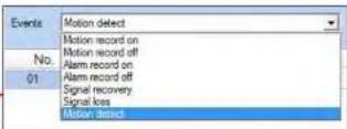
- In the Device drop-down menu, select the Sys tem.
CMS-DH Central Management Software
Result
When the camera detects motion, a pop-up window appears on the bottom-right corner of the screen to alert you.
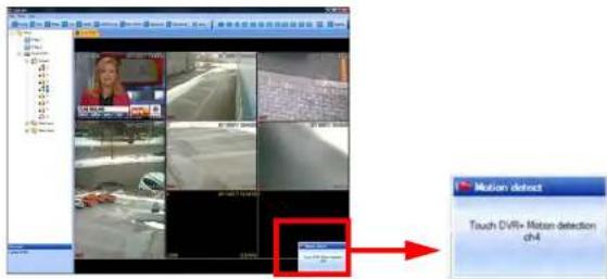
text_image
Motion defrost Touch DVR+ Moton detection ch4Setting Video pop-up notifications
You can configure CMS-DH to produce video pop-up windows when an event occurs.
To configure CMS-DH to produce video pop-up events:
-
Expand the menu tree under the desired DVR that you wish to configure.
-
Right-click on the camera you wish to set alerts for, and click Post E vent Action.
CMS-DH Central Management Software
- In the Events drop-down menu, select the type of event that will trigger CMS-DH to produce a pop-up window when an event is detected.

text_image
Events Motion detect Motion record on Motion record off Alarm record on 01 Alarm record off Signal recovery Signal kess Motion detect- In the Device drop-down menu, select the name of your DVR.

text_image
Post Event Action Events: Notice desert No Device Sub Type Su 01 System Sound System Touch EVH-- Under the Sub Type drop-down menu, select Came ra.
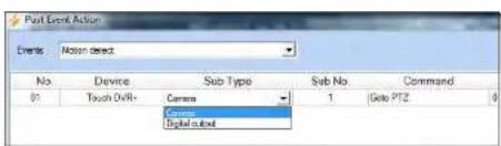
text_image
Post Event Action Events: Motion detect No. Device Sub Type Sub No. Command B1 Touch DVR+ Camera 1 Gate PTZ 0 Camera Digital output-
Under Su b No., select the channel number you wish to appear as a pop-up alert.
-
Under Command, select Live Video.

text_image
Post Event Action Event: Post Event No Device Sub Type Sub No Command Parameter After 0 Touch Office Console 1 Gsta F12 0CMS-DH Central Management Software
Configuring other Post Action Events
Under the Command drop-down menu, there are several commands that CMS-DH can output.
- GoTo PTZ: Opens the PTZ camera.
• Auto Tour: Opens the PTZ camera and starts the Auto Tour.
• Auto Pan: Opens the PTZ camera and starts the Auto Pan feature. - Auto Tilt: Opens the PTZ camera and causes the PTZ camera to Auto Tilt.
• Live: Opens a live video window.
• Record: Begins live recording.

text_image
Goto PTZ Auto Tour Auto Pan Auto Tilt Snapshot Live Video RecordPOS Data Search
The POS Data Search function is not available for the DH200+ series.

CMS-DH Central Management Software
Running CMS-DH on multiple monitors
CMS-DH can support a maximum of 8 monitors on a single system. Running 8 monitors is extremely resource intensive. The recommended system specifications is listed below. If your system does not meet the requirements below, you may experience slow system performance.
Minimum system recommendations to run CMS-DH on multiple monitors
• Intel Core i5 or i7 processor
- 6 GB of RAM
- A motherboard that can support up to four (4) PCI-E video cards
• Geforce 9500 GT video card, 1GB or greater
To run CMS-DH on multiple monitors:
-
Connect to CMS-DH. Open the desired DVR's / E-Maps etc. that you wish to view.
-
Drag the desired tabs to a different monitor.

text_image
CMS-DH File Edit View Tool Online Tree E-Map Live Health CMS-DH Log New VDVR Sequence Tab unlock Close + Group E-Map 1 Touch DVRs E-Map 1 Drag the tab out to move it into a different screen.- Repeat as required.
iSMS Client (Remote Viewing on the Mac)
The iSMS Client allows you to remotely connect and configure your DVR using the Safari browser in Mac OSX 10.6.
System Requirements
Your system must meet or exceed the requirements below before installing the iSMS Client:
- Operating System: Mac OSX 10.6 or later
• CPU: Intel Core Duo series CPU or higher
• Memory (RAM): 1024 GB
• Video Card memory: 256 MB
• Free Hard Drive space: 2GB
• Video Resolution: 1024 x 768
Prerequisites
- Download the iSMS client from www.digimerge.com, under the DH230's product page
- Port 80 (or whichever port your system is using) must be port forwarded to your router
- You must create a DDNS account, and have the DDNS settings configured in your DVR
• The DVR must have internet access - You must have a Digimerge DDNS address to log in remotely
Installation Stone
Using the iSMS Client
Using the iSMS Client
To open the iSMS client:
- Locate the iSMS program in the Applications folder.

- Double-click the iSMS icon() to start the program. The iSMS login window opens.

text_image
Sms Visit Port User Name admin Password ****** Video Mode NTSC PAL Backup Users > <><><><>BACKUP> Connect: File Open DeleteEnter the DVR's DDNS address here
File Open button
Note
The iSMS client supports a maximum of three (3) connected users.
Click to change save directory
To log in to your DVR remotely:
- In the Host Port field, enter the DDNS address of your DVR in full, including the port number. (i.e. tomsmith.diqimerge.net:80)
- In the User Name field, enter admin.
- In the Password field, enter your DVD password (by default: nonnon)
Using the iSMS Client
iSMS Interface
The iSMS Interface displays all connected channels of your DVR.
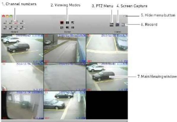
text_image
1. Channel numbers 2. Viewing Modes 3. PTZ Menu 4. Screen Capture 5. Hide menu button 6. Record 7. Main Viewing window- Channel Numbers: Click the desired channel to view in full screen.
- Viewing Modes: Click the icons to switch viewing modes (i.e split screen, quad-view)
- PTZ Menu: Opens the PTZ menu.
- Screen Capture: Takes a picture of the main viewing window, and saves it to the hard drive to the save directory you specify.
- Hide Menu button: Collapses the tool bar and hides the interface functions.
- Record: Click to record video of the selected channel. Click again to stop recording. The file
Using the iSMS Client
To take a screen capture:

-
Click the Screen Capture button |
-
Enter an image name into the blank field, and then click Save or click Print.

text_image
2019年6月10日 1:15:00 1.0.2 Copyright: A, 1919-10-31 13:45:11:00 Video Captive Image! Save PrintEnter image name
To record live video:


-
Click the Record button ( ). The record button turns red
-
Click the Record button again to stop the recording.
NOTE: The video file saves into a folder to the save directory you specify.
To view recorded video:
- In the tool bar, click DVR→File Play.
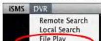
Using the iSMS Client
Configuring OSD Settings
The iSMS interface can be customized to show less or more information.
To configure the iSMS display settings:
- From the tool bar, click iSMS→Preferences.
- Select the display settings that you wish to remove by clicking the checkboxes.
- Close the menu to save your settings.

text_image
iSMS DVR About iSMS Preferences... Quit iSMS Q Audio Mode Camera No. Camera Title Date Time Status Frame RateSearching for video remotely
You can search for video from your DVR remotely, and back up the file to your local hard drive.
To search for video on your DVR remotely:
- From the tool bar, click DVR→Remote Search.
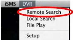
text_image
iSMS DVR Remote Search Local Search File Play SetupUsing the iSMS Client

text_image
Remote Springs Month / Year 2018/13 Calendar Download Playback LNG Channel selection Hour Minute Normal Moderate (Orange/Orange) 7 8 9 10 11 12 13 14 15 16 17 18 19 20 20 21 22 23 24 25 26 27 28 29 30 Channel selection- Click the Playback button to begin viewing.
OR
Click the Download button to save the video to your default save directory.
Download Progress bar

text_image
Progress: 56 % Start: 2010/11/10 11:10:00 End: 2010/11/10 11:14:59 Close Disk Size: 202.5 GB / 232.6 GB Download Path: /Users/userUsing the iSMS Client
Playback Window
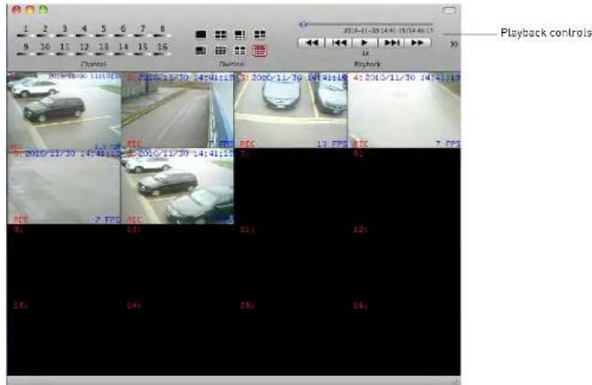
text_image
1 2 3 4 5 6 7 8 9 10 11 12 13 14 15 16 Channel Playback controls 2010-01-30 14:41:15 14:41:16 41:30:11/30 14:41:17 2010-01-30 14:41:15 14:41:16 41:30:11/30 14:41:17 2010-01-30 14:41:15 14:41:16 41:30:11/30 14:41:16 2010-01-30 14:41:15 14:41:16 41:30:11/30 14:41:17 2010-01-30 14:41:15 14:41:16 41:30:11/30 14:41:18 2010-01-30 14:41:15 14:41:16 41:30:11/30 14:41:18 2010-01-30 14:41:15 14:41:16 41:30:11/30 14:41:19 2010-01-30 14:41:15 14:41:16 41:30:11/30 14:41:20 2010-01-30 14:41:15 14:41:20 Playback controls- Use the Playback Controls to manipulate video speed

text_image
2010-11-30 14:41:19/14:46:15 Drag the video slider to skip through the video x Pla back Play... Click the Rewind or Fast Forward buttons repeatedly to increase the speed The Reverse Clips endUsing the iSMS Client
Searching for video locally
To search for local videos saved on your hard drive:
- From the toolbar, click DVR→Local Search.
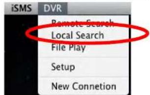
text_image
iSMS DVR Remote Search Local Search File Play Setup New Connetion- From the Remote Search menu, perform the following:
a. Select the Month/Year
b. From the Calendar, select the date.
c. Select the Hour and Minute
d. Select the channels you wish to search under by clicking the check boxes

text_image
Local Search Month / Year Calendar Playback Playback Hour Minutes 10 20 30 40 50 60 70 80 90 100 110 120 130 140 150 160 170 180 190 200 210 220 230 240 250 260 270 280 290 300 310 320 330 340 350 360 370 380 390 400 410 420 430 440 450 460 470 480 490 500 510 520 530 540 550 560 570 580 590 600 610 620 630 640 650 660 670 680 690 700 710 720 730 740 750 760 770 780 790 800 810 820 830 840 850 860 870 880 890 900 910 920 930 940 950 960 970 980 990 1000Using the iSMS Client
Configuring PTZ settings
If your DVR has a PTZ (pan tilt zoom) camera installed, you can control the PTZ camera through the PTZ menu.
To open the PTZ menu:

text_image
• Click from the main interface. PTZPTZ Controls
To control your PTZ camera, click on the channel that your PTZ camera is connected to.

| Plan & Tilt Directional Psd | |
| Plan & Tilt | |
| Zoom in | |
| Zoom In | |
| Zoom Out | |
| Zoom Out | |
| Focus | |
Using the iSMS Client
PTZ Controls cont'd.
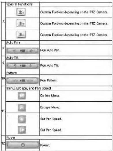
text_image
Special Functions Custom Fuciens depending on the PTZ Camera. Custom Fuciens depending on the PTZ Camera. Custom Fuciens depending on the PTZ Camera. Auto Pan Run Auto Pan. Auto Tilt Run Auto Tilt. Pattern Run Pattern. Menu, Escape, and Pan Speed Go into Menu. Escape Menu. Sat Pan Speed. Sat Pan Speed. Power Power.Using the iSMS Client
Configuring PTZ Protocols in the iSMS Client
You must enter the PTZ camera protocols and settings in the iSMS client before you can control
the PTZ camera.
To configure PTZ camera settings:
- From the toolbar, click DVR→Setup.

- From the Setup window, click Camera.
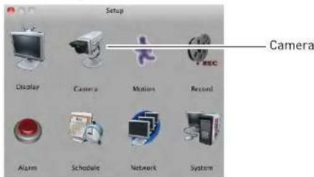
text_image
Setup Camera Display Camera Motion Record Alarm Schedule Network System- Click the channel with the PTZ camera.

Select channel with PTZ camera
Configuring the iSMS Client
Configuring the iSMS Client
The iSMS client features a Setup menu that allows you to configure settings in your DVR remotely.
The following menus are available for configuration:
- Display
- Camera
- Motion
- Record
- Alarm
- Schedule
- Network
- System
To open the Setup Menu:
- From the toolbar, click DVR→Setup.
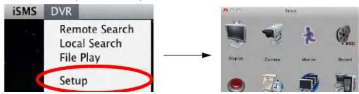
text_image
iSMS DVR Remote Search Local Search File Play SetupiPhone: Digi iMobile Touch App
Digi iMobile Touch is an app that allows you to remotely view your
DH200/200+/230/250 series DVR on your iPhone. There are two versions of the Digi iMobile Touch app:
- Digi iMobile Touch Lite (Free)
- Digi iMobile Touch Pro (Payment required)
Digi iMobile Touch Lite VS Digi iMobile Touch Pro
| Feature Lite version Pro version | ||
| Channels supported 16 16 | ||
| Video Search feature No Yes | ||
| Record On/Off control No Yes | ||
| Schedule On/Off control No Yes | ||
| Alarm On/Off control No Yes | ||
| Number of DVRs Supported | 2 | 10 |
| Price | Free | $9.99 from the Apple App Store* |
*Prices subject to change. Please check the Apple App Store for the latest pricing.
iPhone: Digi iMobile Touch App
Prerequisites
- Port 80 (or whichever port your system is using) must be port forwarded to your router
- You must create a DDNS account, and have the DDNS settings configured in your DVR
• The DVR must have internet access - You must have a Digimerge DDNS address to log in remotely
• An iTunes account
NOTE: You will need to create an iTunes account before you can download the app. An iTunes store account requires a valid credit card number. Your credit card number will be charged if you download Digi iMobile Touch PRO. The Digi iMobile Touch Lite app is free of charge.
Installation Steps
- Search for Digi iMobile Touch Lite or Digi iMobile Touch Pro in the iTunes store. Follow the onscreen instructions to install the app.
Digi iMobile Touch Lite
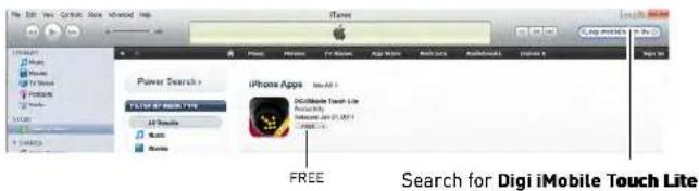
text_image
Power Search > F1/10/F1/M1/M2/M3/M4/M5/M6/M7/M8/M9/M10/M11/M12/M13/M14/M15/M16/M17/M18/M19/M20/M21/M22/M23/M24/M25/M26/M27/M28/M29/M30/M31/M32/M33/M34/M35/M36/M37/M38/M39/M40/M41/M42/M43/M44/M45/M46/M47/M48/M49/M50/M51/M52/M53/M54/M55/M56/M57/M58/M59/M60/M61/M62/M63/M64/M65/M66/M67/M68/M69/M70/M71/M72/M73/M74/M75/M76/M77/M78/M79/M80 iPhone Apps Add All 1 Digi iMobile Touch Lite Add All 2 Add All 3 Add All 4 Add All 5 Add All 6 Add All 7 Add All 8 Add All 9 Add All 10 Add All 11 Add All 12 Add All 13 Add All 14 Add All 15 Add All 16 Add All 17 Add All 18 Add All 19 Add All 20 Add All 21 Add All 22 Add All 23 Add All 24 Add All 25 Add All 26 Add All 27 Add All 28 Add All 29 Add All 30 Add All 31 Add All 32 Add All 33 Add All 34 Add All 35 Add All 36 Add All 37 Add All 38 Add All 39 Add All 40 Add All 41 Add All 42 Add All 43 Add All 44 Add All 45 Add All 46 Add All 47 Add All 48 Add All 49 Add All 50 Add All 51 Add All 52 Add All 53 Add All 54 Add All 55 Add All 56 Add All 57 Add All 58 Add All 59 Add All 60 Add All 61 Add All 62 Add All 63 Add All 64 Add All 65 Add All 66 Add All 67 Add All 68 Add All 69 Add All 70 Add All 71 Add All 72 Add All 73 Add All 74 Add All 75 Add All 76 Add All 77 Add All 78 Add All 79 Add All 80 Add All 81 Add All 82 Add All 83 Add All 84 Add All 85 Add All 86 Add All 87 Add All 88 Add All 89 Add All 90 Add All 91 Add All 92 Add All 93 Add All 94 Add All 95 Add All 96 Add All 97 Add All 98 Add All 99 Add All 100 FREE Search for Digi iMobile Touch LiteDigi iMobile Touch Pro

Configuring Digi iMobile Touch Lite/Pro
Once you have installed the application, enter your DVR's information to connect remotely.
To enter your DVR information into Digi iMobile Touch Lite:
- Tap the + butt on.
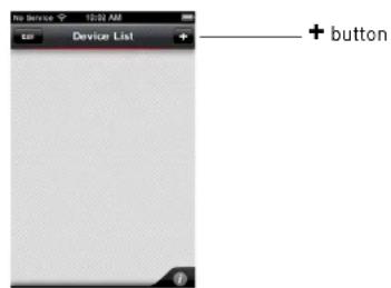
text_image
Device List + button
Digi iMobile Touch Lite users:
You can add a maximum of two (2) DVRs to the Device list.

Digi iMobile Touch Pro users:
You can add a maximum of ten (10) DVRs to the Device list.
2. Enter the following:
-
Name: Enter the DVR name of your choice.
• IP/Host: -
Enter the local IP of the DVR, followed by a colon, followed by the DVR's port number OR
- Enter the DDNS address of the DVR, followed by a colon, followed by the DVR's port number (i.e. touch.digimerge.net:80)
- Username: Enter the DVR's user name (by default, admin)
- Password: Enter the DVR's password (by default, 000000)
iPhone: Digi iMobile Touch App
Connecting to your DVR
- From the Device List, tap the name of your DVR to connect.
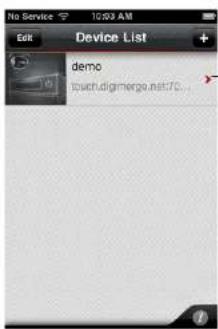
text_image
No Service 12:53 AM Edit Device List + demo touch.digmerge.net:70...Tap the name of your DVR
Digi iMobile Touch Lite Interface
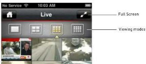
text_image
No Service 10:03 AM Live Full Screen Viewing modesiPhone: Digi iMobile Touch App
Digi iMobile Touch Pro Interface

text_image
Live Full Screen Search DVR Take screenshot* PTZ Toggle on screen display (OSD) Opens Device Control menu Viewing modes test* Screenshots are stored in your iPhone's photo album.
About the Search and Control menus
The Search and Control menus are exclusive to Digi iMobile Touch Pro. The search menu allows you to search and playback video on your DVR.
The Control menu allows you to turn recording on or off, enable or disable relay control, and turn schedule recording on or off.
iPhone: Digi iMobile Touch App
Changing Viewing Modes
- Touch to change viewing modes.
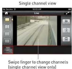
text_image
Single channel view Live Swipe finger to change channels (single channel view only)
text_image
Quad View Live 10:03 AM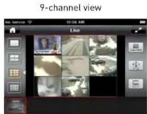
text_image
9-channel view Live
text_image
16-channel view LiveiPhone: Digi iMobile Touch App
Toggling the On Screen Display (OSD)
- Tap the OSD button to turn the OSD on/off. The OSD displays the recording status and DVR time.

text_image
OSD Off No Service 10:04 AM Live OSD on No Service 10:04 AM Live O5D button OVR TimeDigi iMobile Touch Lite interface shown
PTZ
To control connected PTZ cameras to the DVR:
- Select the channel that the PTZ camera is connected to in single channel mode.
- Tap the PTZ button.
- Tap the arrows to pan/tilt the camera. Tap + and - to zoom in and o ut.

iPhone: Digi iMobile Touch App
Digi iMobile Touch Pro features
Search
The Search menu allows you to search for recorded video on your DVR.
To search for video:
- Tap the Se arch icon

- Tap the arrows to select the month, and then tap the desired date to begin the search.
| Apr, 2011 | ||||||
| SUN | MON | TUE | WED | THU | FRI | EAT |
| 27 | 28 | 29 | 30 | 31 | 1 | 2 |
| 3 | 4 | 5 | 6 | 7 | 8 | 9 |
| 10 | 11 | 12 | 13 | 14 | 15 | 16 |
| 17 | 18 | 19 | 20 | 21 | 22 | 23 |
| 24 | 25 | 26 | 27 | 28 | 29 | 30 |
Tap here to select month
Tap here to select date
- Tap the hour that you wish to begin the search. Next, drag the Min button to search for the minute that you wish to search.

text_image
Apr. 2011 2011-04-07 Hour 01 02 03 04 05 06 07 08 09 10 11 12 Alarm Motion Normal 13 14 15 16 17 18 19 20 21 22 23 24- Tap here to select desired hour
iPhone: Digi iMobile Touch App
- Use the playback controls to pause, fast forward, or rewind video.
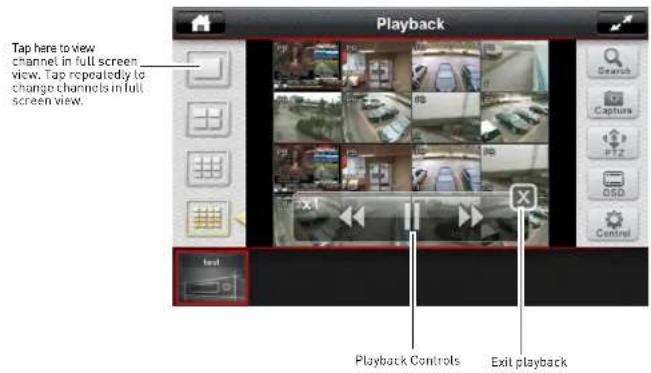
text_image
Playback Tap here to view channel in full screen view. Tap repeatedly to change channels in full screen view. Text Playback Controls Exit playbackDevice Control
The Device Control menu allows you to turn recording, scheduled recording and relay alarms on or off.
To configure the Device menu:
- Tap the Control button | ).

Tap here to close the Device Control menu.
Android: Digi iMobile Touch Lite App
Digi iMobile Touch Lite is an Android app that allows you to remotely view your DH200/ 200+/230/ 250 series DVR.
NOTE: Digi iMobile Touch Lite is capable of viewing only.
NOTE: These instructions are based on the HTC Wildfire smartphone. For specific installation instructions, consult your smartphone's user's manual.
Compatible Devices
- Android OS (2.1 and above, touch screen models only)
• Digimerge DH200/200+/230/250 Series DVR
Prerequisites
- Port 80 (or whichever port your system is using) must be port forwarded to your router
- You must create a DDNS account, and have the DDNS settings configured in your DVR
• The DVR must have internet access - You must have a Digimerge DDNS address to log in remotely
• An Android Market account
NOTE: You will need to create an Android Market account to download the app.
Installation Steps
Android: Digi iMobile Touch Lite App
Configuring Digi iMobile Touch Lite
Once you have installed the application, enter your DVR's information to connect remotely.
To enter your DVR information into Digi iMobile Touch Lite:
- Press the Menu button on your phone, and then tap Add De vice.

text_image
Device List Add Device Tap Add Device You can add a maximum of two (2) DVRs to the Device list.2. Enter the following:
-
Name: Enter the DVR name of your choice.
• IP/Host: -
Enter the local IP of the DVR, followed by a colon, followed by the DVR's port number OR
- Enter the DDNS address of the DVR, followed by a colon, followed by the DVR's port number (i.e. touch.digimerge.net:80)
- Username: Enter the DVR's user name (by default, admin)
- Password: Enter the DVR's password (by default, 000000)
Android: Digi iMobile Touch Lite App
Connecting to your DVR
- From the Device List, tap the name of your DVR to connect.
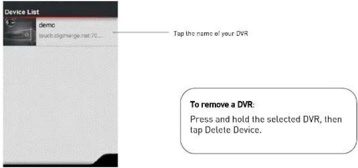
text_image
Device List demo touch digimerge.net 70... Tap the name of your DVR To remove a DVR: Press and hold the selected DVR, then tap Delete Device.Digi iMobile Touch Lite Interface

text_image
Live Viewing modesAndroid: Digi iMobile Touch Lite App
Changing Viewing Modes
- Touch to change viewing modes.
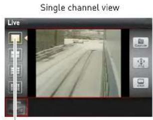
text_image
Single channel view LiveTap the single channel button to change channels

text_image
Quad View Live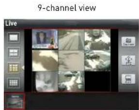
text_image
9-channel view Live
text_image
16-channel view LiveAndroid: Digi iMobile Touch Lite App
Toggling the On Screen Display (OSD)
- Tap the OSD button to turn the OSD on/off. The OSD displays the recording status and DVR time.
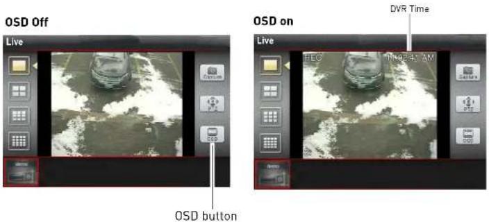
text_image
OSD Off Live OSD button OSD on Live HCG The 2:47 AM DVR TimePTZ
To control connected PTZ cameras to the DVR:
- Select the channel that the PTZ camera is connected to in single channel mode.
- Tap the PTZ button.
- Tap the arrows to pan/tilt the camera. Tap + and - to zoom in and out.
Installing the BDVRViewer App on your Blackberry
INSTALLING THE BDVRVIEWER APP ON YOUR BLACKBERRY
The BDVRViewer application allows you to remotely view your DVR on your Blackberry.
Prerequisites
• Blackberry 9000 or 9700 only
• An APN name, obtained from your Blackberry service provider (Digimerge does not provide this)
• A DDNS account from https://secure.digimerge.net/webapp/
You must port forward your router before you can connect to your system using a mobile device
Step 1 of 4: Download the BDVRViewer Application
- Open the web browser on your Blackberry, and go to http://mobile.digi1.net/java/
- Click on the BlackBerry Test Release link.

text_image
http://rnable.digi1.net/ 2 3G F2 T-ml JavaViewer Release Nokia Strains Methods Test Release BlackBerry Test Release BlackBerry Test Instruction: Please clear your explorer cache 1. Install with All Yes 2. Check APN setting: Option ->Advanced->TCP/IP->APN 3. Check Security: Option ->Application ->BDVERviewer-- Option->Edit Auth->All Allow BlackBerry Test ReleaseInstalling the BDVRViewer App on your Blackberry
Step 2 of 4: Clear your browser cache
You must clear your browser cache for the BDVRViewer application to run properly.
- Open the web browser on your Blackberry, and then press
- Click Options.

text_image
Internet Browser Select History Call Voice Mail Bookmarks Options Show Symbols Switch Application 3G To Tall kBerry... Show Ca... Options net/java/- Beside Content Cache, click the Cl ear button.

text_image
Cache Operations Clear History Content Cache Size: 1.6 KB Clear Pushed Content Size: 39.6 KB Clear button- Exit the web browser to save your changes.
Installing the BDVRViewer App on your Blackberry
Step 3 of 4: Enable APN (Access Point Name)
In order for BDVRViewer to function, you must enable APN (Access Point Name) on your Blackberry. Contact your service provider for your Blackberry's APN name.
To enable APN:
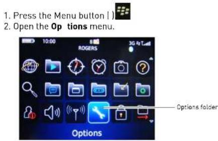
text_image
1. Press the Menu button | 2. Open the Op tions menu. 10:00 ROGERS 3G To Tcell Options folder Options3. Select Advanced Options → TCP/IP

text_image
Options About Advanced Options Applications Auto On/Off AutoText Bluetooth Custom Dictionary Date/Time Advanced Options Default Services GPS Host Routing Table Maps Service Book SIM Card TCP/IP Wireless Update- Select the checkbox beside APN Settings to enable APN
Installing the BDVRViewer App on your Blackberry
Step 4 of 4: Log in to BDVRViewer
- Press the Menu button | ) then open the Downloads folder.
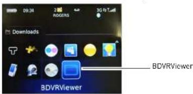
text_image
09:34 ROGERS 3G Fi T Downloads BDVRViewer BDVRViewer- Click on the BD VRViewer icon.
- Enter the DVR DDNS address, port number, ID, and password, and then click LO GIN.
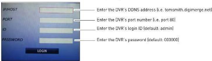
text_image
IP/HOST PORT ID PASSWORD LOGIN Enter the DVR's DDNS address (i.e. tomsmith.digimerge.net) Enter the DVR's port number (i.e. port 80) Enter the DVR's login ID (default: admin) Enter the DVR's password (default: 000000)- A network security window opens. Click Ye s to connect to the DVR.

text_image
The application BDVRViewer has attempted to access a low-level network connection. But it doesAPPENDIX A: SYSTEM SPECIFICATIONS
DH230 Specs
Description Specification
Multiple Function Pentaplex
| Video Input 4/8/16 x 1.0Vp-p, CVBS, 75ohms, BNC |
| Video Output MAIN: 1 HDMI, 1 VGA, 1 Composite / SPOT: 1 (Programmable)/ Looping: 4/8/16 |
| Audio Input 1 x line-in (RCA) |
| Audio Output 1 x line-out (RCA) |
| Communication | RS-422, Ethernet (10/100 Base-T), USB 2.0 |
Port
Power 12V, 6A
Compression H.264
Data Size 0.6-7 Mbps/ch @ 30fps
Live Display 720*480(NTSC) / 720*576(PAL)
Resolution
Live Display Speed Real Time
Display Split Mode 1,4,6,7,8,9,10,13,16
Operating System Linux (embedded)
Recording 120 fps 720x480[NTSC], 100fps 720x576[PAL]
Resolution 240fps 720x240(NTSC). 200fps 720x288(PAL)
| Description Specification | |
| Backup Storage Interface | 2x USB 2.0, Network |
| External Backup Device | External HDD, DVD-RW, Flash Memory Stick |
| Storage HDD | Up to 2 Internal HDD (4ch, MAX 4TB) / Up to 3HDD (8/16ch w/o optical drive, MAX 6TB) |
| Optical Drive Optional internal | |
| Time Zone Selectable | |
| DST Auto | |
| Time Synchronization | Supported via NTP server |
| Network Interface RJ45/Ethernet | |
| Network Line LAN, WAN, Internet | |
| Network Transmission Speed | Max 480FPS |
| Pre-Alarm/ Post-Alarm | 5 seconds ~ 5 minutes, programmable per camera |
| DDNS Digimerge DDNS | |
| Event Routing | Source: Alarm, Motion, Video Loss, System Power Loss, HDD Failure, Fan Lock, Temp Action: Record, system buzzer, alarm relay spot, e-mail, PTZ event |
| Controls Mouse, Optional IR remote, front panel keys | |
| Firmware Upgrade USB | |
| Dimensions | 360x360x70mm/ 14.1 x 14.1 x 2.75" |
DH250 Specs
| Description Specification | |
| Multiple Function Pentaplex | |
| Video Input 8/16 x 1.0Vp-p, CVBS, 75ohms, BNC | |
| Video Output Main: 1 HDMI, 1 VGA, 1 CompositeSpot: 1(8), 3I16I ProgrammableLooping: 8/16 | |
| Audio Input 8/16 x line-in, DSUB | |
| Image Size | 4-19 Kbyte [720x480], 3-14 Kbyte [720x240] 2-10 Kbyte (360x240) |
| Audio Output 8/16 - 1(RCA) | |
| Communication Port | RS-232C, RS-422, 2*Ethernet [Gigabit], USB 2.0 |
| Power 100-240V, Universal Voltage | |
| Compression H.264 | |
| Data Size 0.19-0.3 Mbps/ch @30fps [CIF,Low-D1,Ultra] | |
| Live Display Resolution | 720*480(NTSC) / 720*576|PAL| |
| Live Display Speed Real Time | |
| Display Split Mode 1, 4, 6, 7, 8, 9, 10, 13, 16 | |
| Operating System Linux [embedded] | |
| Recording Resolution | 480fps @ D1: 720x480 [NTSC], 400fps 720x576 [PAL]480fps: 720x240 (NTSC), 400fps 720x288 [PAL]480fps: 360x240 (NTSC), 400fps 260x288 [PAL] |
| Description Specification | |
| Backup Storage Interface | 2 x USB 2.0, 2 xeSATA (SATA-II), 2-Gigabit Lan |
| External Backup Device | External HDD, DVD-RW, Flash Memory Stick |
| Storage HDD | 4 x 500GB HDD (Max 6TB) w/o built-in DVD-RW, 100% duty cycle, 16 MB expanded cache |
| Optical Drive Optional internal | |
| Time Zone Selectable | |
| DST Auto | |
| Time Synchronization | Supported via NTP server |
| Network Interface RJ45/Ethernet | |
| Network Line LAN, WAN, Internet | |
| Network Transmission Speed | Max 480FPS |
| Pre-Alarm/ Post-Alarm | 5 seconds ~ 5 minutes, programmable per camera |
| DDNS Digimerge DDNS | |
| Event Routing | Source: Alarm, Motion, Video Loss, System Power Loss, HDD Failure, Fan Lock, Temp Action: Record, system buzzer, alarm relay spot, e-mail, PTZ event |
| Controls Mouse, Optional IR remote, front panel keys | |
| Firmware Upgrade USB, Network | |
| Dimensions | 430x 450 x 103mm / 16.9 x 17.7 x 4" |
APPENDIX B: SETTING UP REMOTE VIEWING
Setting up the Remote Viewing Feature requires several steps. Networking skills are required to correctly configure the remote viewing functions.
What Do I Need?
- DVR System
• A PC with the installed CMS-DH software - A router (not provided with the system) and High Speed Cable or DSL Internet Connectivity (for remote viewing outside your network)
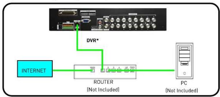
flowchart
graph TD
    A["INTERNET"] --> B["ROUTER (Not Included)"]
    B --> C["PC (Not Included)"]
    D["DVR*"] --> B
Appendix B: Setting up Remote Viewing
How Do I Find My IP and MAC addresses?
The IP and MAC address of your system are necessary for DDNS setup. DDNS allows you to view and control your system from a remote location.

text_image
SYSTEM GENERAL TIME ACCOUNT UPDATE INFO SW VERSION X5K-APP-0.131.0.38 DOMAIN NAME SYS1 MAC 00:02:F1:23:E7:F1 LANGUAGE ENGLISH NETWORK 192.168.1.135:80 RECORD DISK 160G DISK SUMMARY 1 STREAM, 0 MIRROR SYSTEM HEALTH TEMP: GOOD VOLT: GOOD MAC address IP address & port numberTo find your IP and MAC address using the remote control:
- Press the INFO button.
To find your IP and MAC address using the mouse:
- Open the MAIN MENU and select SYSTEM.
- Under the INFO tab you will find your system's IP address and MAC address.
Finding Your External IP Address
How Do I Enable Port Forwarding?
You need to enable port forwarding on your router to allow for external communications with your system for the following port:
• 80
Computers, DVRs, and other devices inside your network can only communicate directly with each other within the internal network. Computers and systems outside your network cannot directly communicate with these devices. When a system on the internal network needs to send or receive information from a system outside the network (i.e. from the Internet), the information is sent to the router.
NETWORK EXAMPLE

flowchart
graph TD
    A["Router External IP 216.13.154.34"] --> B["Router Internal IP 192.168.0.1"]
    B --> C["PC Internal IP 192.168.0.2"]
    B --> D["DVR Internal IP 192.168.0.3"]
    D --> E["Internal NetworkInternet"]
    E --> F["Red Arrow pointing to Router"]
Appendix C: Digimerge Auto Port Forward Wizard
APPENDIX C: DIGIMERGE AUTO PORT FORWARD WIZARD
The Digimerge Auto Port Forwarding Wizard is an exclusive software that easily automates router port forwarding. Before setting up a DDNS account, it is recommended to run the Auto Port Forwarding Wizard to port forward the required ports.
Installation
To install the Digimerge Auto Port Forwarding Wizard:
- Insert the system's software CD, and follow the instructions to launch the Digimerge Auto Port Forwarding Wizard software.
- The installation window opens.
- Click Ne xt to continue.

text_image
Digimerge Auto Port Forwarding Setup Welcome Welcome to the installed for Digimerge Auto Port Forwarding Setup To confirm recommended that we will allow all Windows processors then continuing with this connection. If you have any other programs coming, you should then Cancel, or use the next program, and can be further install. Otherwise, click then to continue. Click Next Digimerge Auto Port Forwarding Setup Installation Setup: Where we should like Digimerge Auto Port Forwarding is to be checked? This software will not be installed for this installed setup. To select a specific location, all rights are available, or it is required. Choose to choose from existing setup. Install Digimerge Auto Port Forwarding Setup: Program Next Digimerge Auto Port Forwarding Cancel Save amount: $50000 Open available or selected then: 37.12.03 Select installation directory (optional)- Click the Change button to change the default installation directory (optionall). Click the Next
Appendix C: Digimerge Auto Port Forward Wizard
- Click the Next button and then click Finish to complete the software installation.

text_image
Digimerge Auto Port Forwarding Start Ready to install This tool now ready to install Digimerge Auto Port Forwarding 1.0.3 This installed has been enough information to make Digimerge Auto Port Forwarding on your controller. The following settings will be used: Install Value - C:\Program Files\Digimerge Auto Port Forwarding\ Services Provider - Digimerge Auto Port Forwarding Please click Next to press your desktop. Click Next Cancel Installation Successful The Digimerge Auto Port Forwarding 1.0.3 installation is complete. Thank you for choosing Digimerge Auto Port Forwarding Please click Next to exit this window. Finish button double-click the Digimerge Auto Port Forwarding shortcut ( If I'm not complete, your desktop to start- Double-click the Digimerge Auto Port Forwarding shortcut (If your desktop to start the program.
Obtaining Your Router Model Number and Version
On most routers, the model and version number can be found underneath the router, printed on a sticker.
Example

text_image
NETGEAR® Wireless-G Router WGR614 v9 Wireless-G Router WGR614 v9 • WGR614 refers to the model n• WGR614 refers to the model number
Configuration

You must have the following before you configure the software:
- Your router's model number and version number
- Your router's user name and password
- Your Digimerge device's IP address
- Your Digimerge device's port numbers that require port forwarding
Initial Startup: Select language
- Click the Language drop-down menu and select a language (English, French, Spanish). Click the Start button to continue.
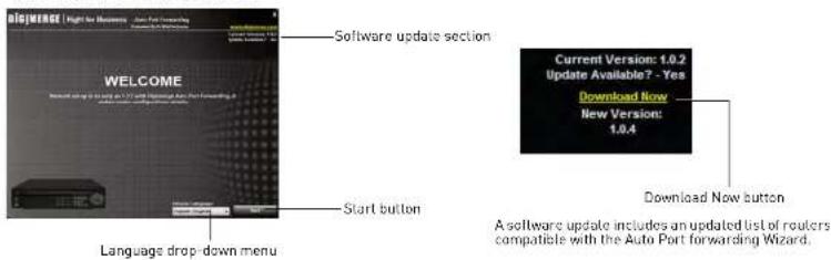
text_image
WELCOME Software update section Current Version: 1.0.2 Update Available? - Yes Download Now New Version: 1.0.4 Start button Language drop-down menu Download Now button A software update includes an updated list of calculers compatible with the Auto Port forwarding Wizard.- If software updates are available, click the Do wnload Now button in the top-right corner.
- Run the update file and install the latest version of the software.
Step 1: Populate the router database
The Auto Port Forwarding Wizard automatically populates a list of current routers, and detects
Appendix C: Digimerge Auto Port Forward Wizard
Step 2: Enter your router settings
- Under the Router drop-down list, select the model of your router. OR
- Click the Search button ( ) to enter the name of your router model.
NOTE: Click the Auto Detect button ( ) if you have a Linksys or Netgear router (works with most Linksys or Netgear models).

text_image
DIGIMERGE | Right for Business - Auto Port Forwarding Recommended by 3D Software Access Search and Auto detect button Enter port 80 under Ports Step 23 Router drop-down list Enable Silent Mode Router IP Router user name & password Route: User: Search and Auto Search and Auto detect button Route: User: Search and Auto Route: User: Search and Auto Route: User: Search and Auto Route: User: Search and Auto Route: User: Search and Auto Route: User: Search and Auto Route: User: Search and Auto Route: User: Search and Auto Route: User: Search and Auto Route: User: Search and Auto Route: User: Search and Auto Route: User: Search and Auto Route: User: Search and Auto Route: Use to access the Route: Use to access the Route: Use to access the Route: Use to access the Route: Use to access the Route: Use to access the Route: Use to access the Route: Use to access the Route: Use to access the Route: Use to access the Route: Use to access the Route: Use to access the Route: Use to access the Route: Use to access the Route: Use to access the Transporter Password S. Move Password Logistage update information Port 80/641 Port 80/641 Port 80/641 Port 80/641 Port 80/641 Port 80/641 Port 80/641 Port 80/641 Port 80/641 Port 80/641 Port 80/641 Port 80/641-
Under Router IP, click the Detect Router IP button (1). The router's IP populates in the blank field. Click OK to exit the prompt.
-
Under Username and Password, enter the router's username and password.
- Optional: Under HTTP Type [default http://] and HTTP Port (default, 80), you may have to change the values depending on your router model. Consult your router manual for details.

Appendix C: Digimerge Auto Port Forward Wizard
Step 3: Update the router settings
- Click the Update Router button.
- You will see your router window open. The Auto Port Forwarding Wizard automatically populates your router with the relevant information. This will take a few moments.

flowchart
graph LR
    A["Update Router button"] --> B["TRENDET"]
    B --> C["Visual Server"]
    C --> D["Control buttons"]
    D --> E["Display / Print"]
    style A fill:#f9f,stroke:#333
    style B fill:#ccf,stroke:#333
    style C fill:#cfc,stroke:#333
    style D fill:#fcc,stroke:#333
    style E fill:#ffc,stroke:#333
- Close the update window when the update finishes.
Step 4: Test your connection
- Click the Test Your Connection button.
- Your system's default browser opens and connects to your Digimerge device.
NOTE: Ensure that Internet Explorer is your system's default internet browser.
NOTE: A window opens that prompts you to enter in your DVR's user name and password (do not enter your DDNS log in information).
NOTE: ActiveX warnings may appear. Accept all ActiveX installation warnings to connect to your system. For details.
Configuring multiple routers
Your network may have two or more connected routers. During the initial launch of the auto port
Appendix C: Digimerge Auto Port Forward Wizard
- The "Possible 1st Router" refers to the router directly connected to your system. This is the router that requires the port forward information.
- The "Possible 2nd Router" refers to the router immediate to the internet connection. This is the router that requires you to configure a DMZ host connection.
Scenario A: Router/Modem combination + Router
- You may have a router/modem combination, with a second router in your network.
Scearnio B: Multiple Routers
- You may have two routers in your network.
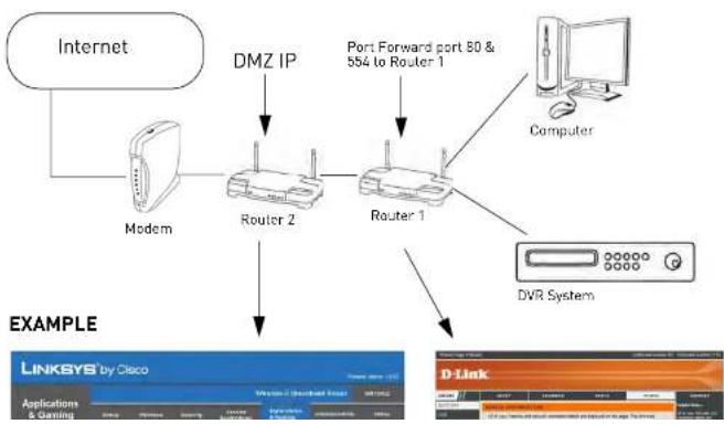
flowchart
graph TD
    A["Internet"] --> B["Modem"]
    B --> C["Router 2"]
    C --> D["Router 1"]
    D --> E["Computer"]
    D --> F["DVR System"]
    C --> G["DMZ IP"]
    D --> H["Port Forward port 80 & 884 to Router 1"]
    style A fill:#f9f,stroke:#333
    style B fill:#ccf,stroke:#333
    style C fill:#cfc,stroke:#333
    style D fill:#fcc,stroke:#333
    style E fill:#cff,stroke:#333
    style F fill:#ffc,stroke:#333
Appendix C: Digimerge Auto Port Forward Wizard
Configuring a DMZ host connection
- Connect to "Router 1" on your network [referred to as "Possible 1st Router" in the Auto Port Forwarding Wizard]. Obtain the IP address of Router 1. Usually this can be found in the "Status" section of your router menu. The IP should begin with "192.168...." This IP address is your DMZ IP.
- Enter the IP address obtained from Router 1 into the DMZ section of Router 2.
- Once you have configured Router 2 with a DMZ connection, run the Auto Port Forwarding Wizard to begin auto port forwarding to Router 1.
- Consult your router's owner's manual for details on configuring DMZ settings.
Example
DMZ stands for Demilitarized Zone. Enabling a DMZ IP on your router enables one of the routers to pass information onto the second router.
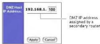
text_image
DMZ Host IP Address: 192.168.1. 100 Apply Cancel DMZ IP address assigned by a secondary routerLocating your Router IP - The Status Page
The "Status Page" of a router normally includes the router's vital information such as the IP address.
EXAMPLE
text_image
Product Page: DDR-415 Hardware Version 32 - Firmware Version 2.35 D-Link DDR-415 SERVICE INFORMATION All of your Internet and network connection details are displayed on this page. The firmware version is also displayed here. GENERAL Time : February-06-04 8:25:10 AMAPPENDIX D: SETTING UP DDNS SERVICE
Digimerge offers a free DDNS service for use with your DVR. A DDNS account allows you to set up a web site address that points back to your local network. The following outlines how to set up your free DDNS account.
To setup your free Digimerge DDNS account:
- In your browser, go to http://ddns.digimerge.net and click Create Account.
- Complete the Account Information fields with your personal information. Complete the Warranty Information with your purchase details (optional).
-
Complete the System Information fields:
-
Product License: Select DH200 from the Product License drop down menu. Note that selecting the DH200 will work for the DH230/DH250 DVRs.
- ←Product Code→ - ←MAC Address→: Locate the MAC address of your (recorded while loading the System)
-
URL Request: Choose a URL for your DDNS connection (i.e. your name, your company or business name, or anything of your choice.)
-
Once the information has been entered, click Create New Account.
-
Your Account information will be sent to you at
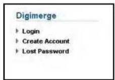
Create a DDNS account
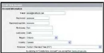
text_image
POST NAME ACCOUNT Account Information Email: amalgamash.com Password: ******** Password: emirn: ******** Phone Name: Send name: Email Region: Ontario Locality: Canada Process: Custom Standard Tree (STT) By clicking on "Create New Account" you accept the business license.Enter personal information
You will need this information for remote access to your system. Record your information below:
Username:
Domain name*:
Password:
* Only the first part of the Domain Name is required for setup on the system. For example, if the full domain name is tomsmith.digimerge.net, you only need to enter tomsmithon the system.
Appendix D: Setting Up DDNS Service
How Do I Enable DDNS On My System?
Once you have registered for free DDNS service, use the information in the confirmation email to configure DDNS settings on your system.

text_image
NETWORK ETHERNET GENERAL EMAIL SMTP DDNS USE OFF DIGIMERGE DOMAIN NAME tomemith USER ID tsmith1 PASSWORD ****** UPDATE TEST STARTTo enable DDNS on your system:
- Open the MAIN MENU and click NETWORK.
- Select the DDNS tab.
- Under USE, select DIG IMERGE.
- Under DOMAIN NAME, enter only the first portion of your DDNS domain from the confirmation email.
For Example:
If your domain name is http://tomsmith.digimerge.net, you only need to enter tomsmith in the text field.
APPENDIX E: SETTING UP MOBILE ACCESS
This guide shows you how to view video streams from your DVR remotely using your iPhone® or Blackberry®.
Before You Begin


You must complete these two steps before starting:
-
Regis ter your DVR with the Digimerge DDNS service. See "Appendix D: Setting Up DDNS Service" on page 148.
-
Enable DDNS on your DVR. See "How Do I Enable DDNS On My System?" on page 150.
Registering your DVR for Mobile Access
Before you can log in to your DVR with a mobile device, you must create a mobile account.
To create a mobile account:
- Go to http://mobil.e.digi1.net/ on your web browser and click Register.

Appendix E: Setting Up Mobile Access
Registering your DVR for Mobile Access Cont'd
- The sign up screen opens.
Enter your desired user ID and password and click Register.
NOTE: Your password must be at least six characters long.

text_image
SIGN UP ID PASSWORD CONFIRM REGISTER CANCELSign up screen. Enter in desired user ID and password.
- The DVR registration window opens. Click ADD D VR.
text_image
MOBILE DVRSTATION - Internet Explorer provided by Dell http://mobile.digi1.net/ Google MOBILE DVRSTATION PageAppendix E: Setting Up Mobile Access
Registering your DVR for Mobile Access Cont'd
- The EDIT DVR INFORMATION window opens.

text_image
EDIT DVR INFOMATION - Internet Explorer provided by Dell http://mobile.digi1.net/ EDIT DVR INFOMATION PAGE NAME DVR DOMAIN NAME PORT 80 USER NAME adults PASSWORD 000000 APPLY CANCEL Internet | Protected Mode: Off 100%DVR registration window. Enter DVR name and DDNS domain name.
- Enter any desired DVR name (the default name is "DVR"). Enter your DDNS domain name.
NOTE: You do not have to enter the entire DDNS address under DOMAIN NAME. For example, if your registered DDNS name is myoffice.digimerge.net, you would enter: myoffice in the DOMAIN NAME field.
text_image
EDIT DVR INFOMATION - Internet Explorer provided by Dell http://mobile.digi1.net/ GoogleAppendix E: Setting Up Mobile Access
Registering your DVR for Mobile Access Cont'd
- Enter your DVR's user name and password. Click the Apply button.
NOTE: If you change the password of the DVR, you must update your account with the latest password.
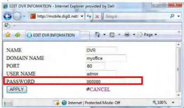
text_image
EDIT DVR INFOMATION - Internet Explorer provided by Dell http://mobile.digi1.net/ EDIT DVR INFOMATION NAME DVR DOMAIN NAME(myoffice) PORT 80 USER NAME hemin PASSWORD 000000 APPLY CANCELOnce you have entered in all the fields, click APPLY to continue.
-
A new window opens that shows: DVR (the name of your dvr), ADD DVR, LOG OUT, SIGN UP. Click on DVR (the name of your dvr).
-
The DVR camera list opens. Click the desired camera to start viewing video feed.

Appendix F: Connecting PTZ Cameras
APPENDIX F: CONNECTING PTZ CAMERAS
You can connect RS-422/485 PTZ cameras [not included] to the PTZ Control Block on the rear panel of the system.

text_image
RELAY ALARM IN RS-422 1 2 3 4 G I A B T+ T- R+ R BNC Connect to T+ and T-DH250 Relay block
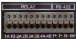
PTZ CAMERA
[not included]
Appendix F: Connecting PTZ Cameras
Using a PTZ Camera
To control a PTZ camera:
- With your PTZ connected to the system, view the active PTZ channel in full-screen.
- Right-click to open the virtual remote, and click the PTZ button.
- Use the virtual remote to control the PTZ.
To open the HELP menu:
- Click the MENU butt on.
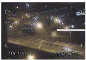
natural_image
Night street scene with illuminated streets and streetlights, no visible text or symbolsMENU button
Drag you mouse cursor within the frame to pan and tilt the camera. You must be in single-channel mode of the PTZ camera for this to work.

- Click on the virtual remote to open the help menu.
The PTZ Help Menu contains the following:
Button Result/Action
ENTER button

- Press to open the PTZ Help Menu; press again to close the menu

Appendix F: Connecting PTZ Cameras
MENU button | Press to open the PTZ Virtual Remote; press again to return to the Short-cut menu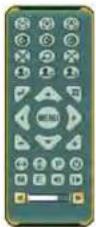 |
Navigation buttons | Press ▲▼ to tilt up/downPress ◀▶ to pan left/right |
Increase/Decrease buttons  | Press + / - to zoom in and out |
| Button Result/Action | |
| [H0WS] | Set PRESET position; Spot Out on the remote controlMove PTZ to a desired locationPress the preset buttonIlluminate Custom 1 |
Appendix F: Connecting PTZ Cameras
 | • Start AUTO TOUR• Press the Auto Tour button• Press + and enter the range of preset and Click ENTER• For example, Auto Tour button, +5 will start the tour of 1-5 presels of the PTZ camera |
 | • PTZ custom function 1; Display on the remote control |
 | • PTZ custom function 2; Zoom on the remote control |
 | • PTZ custom function 3; PTZ on the remote control |
 | • Speed has 8 increments—keep pressing the buttons to increase/decrease speed |
Setting Pre-Sets and Tour
To set a Pre-Set:
- Move the PTZ camera to the desired position.
2 Press the Preset button

PTZ Compatibility List
| # | Model Name | 3X | Speed | Preset | Go to | Tour | A. Pan | A. Tilt | Pat | Me | Esci Enter |
| 1 | PELCO, D | o | o | o | o | o | o | o | o | ||
| 2 | RVT, EZ Protocol | o | o | o | o | o | o | o | o | ||
| 3 | PELCO, P | o | o | o | o | o | o | o | o | ||
| 4 | Hilton, Fastrax 2 | o | o | o | o | o | o | o | o | ||
| 5 | Bosch, Auto Dome | ||||||||||
| 6 | MERIT LINLIN | ||||||||||
| 7 | APPROMEDIA | ||||||||||
| 8 | LG,MULTIXE CAM/DOME | ||||||||||
| 9 | BBV,PROTOCOL V2 |
APPENDIX G: CONNECTING ADDITIONAL EXTERNAL MONITORS
Use the Video port (BNC) on the rear panel of the system to use the Monitor Out function. Monitor Out displays the exact on-screen display of the system.
Use the Spot port (BNC) to use the Spot Out function. Spot Out displays connected cameras on the system.
NOTE: A BNC-to-RCA adapter (not included) is required to connect a monitor with RCA inputs.
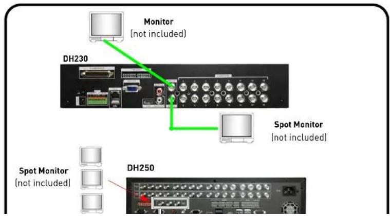
text_image
Monitor (not included) DH230 Spot Monitor (not included) Spot Monitor (not included) DH250Appendix G: Connecting Additional External Monitors
The 75 OHM switch on the back panel of the monitor allows the DVR to compensate for over or under exposed images when connecting monitors to the Loop Out monitor (CAMERA OUT port).
DH230

text_image
CAMERA OUT Connect a octopus cable to connect loop out monitors) CAMERA OUT port (Connect a octopus cable to connect loop out monitors) 75 ohm Channels 1-8 Channels 8-16DH250

natural_image
Front view of a network equipment rack with multiple ports and connectors (no visible text or labels)Appendix H: Connecting Motion / Alarm Devices
APPENDIX H: CONNECTING MOTION / ALARM DEVICES
You can enable motion detection and alarm control from the Main Menu. You can also connect additional motion sensor devices to the system (i.e. motion sensors, door/window sensors). Use a motion detector or sensor to send a signal to the system to begin camera viewing and recording on the matching camera channel (when enabled in the Menu).
To connect an external alarm sensor (ALARM INPUT) to the system:
- Connect the Signal Cable to the desired port in the alarm block.
- Connect the Ground cable to the Ground port (G) in the alarm block.
- Open the MAIN MENU and select DEVICE→ALARM.
- Select the corresponding alarm channel and select INPUT
- Select N.C. (Normally closed) or N.O. (normally open) depending on your alarm/sensor setup.
- Press the ENTER button to save your settings.

The following diagram outlines a general set of connections available with the DVR.
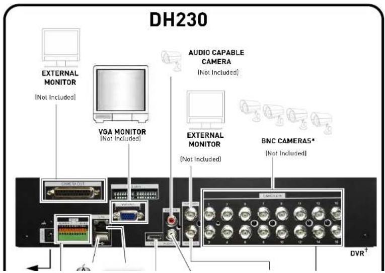
text_image
DH230 EXTERNAL MONITOR [Not Included] VGA MONITOR [Not Included] AUDIO CAPABLE CAMERA [Not Included] EXTERNAL MONITOR [Not Included] BNC CAMERAS* [Not Included] CAMERA OUT DVR†Appendix I: Full Connectivity Diagram
The following diagram outlines a general set of connections available with the DVR.

text_image
DH250 BNC CAMERAS* (Not included) EXTERNAL MONITOR (Not Included) POWER ROUTER (Not Included) ALARM / SENSOR (Not Included) PTZ CAMERA (Not Included) MOUSE AUDIO CAPABLE CAMERAAPPENDIX J: REPLACING THE HARD DRIVE
The system comes with a pre-installed 3.5" SATA hard drive. The DH230 supports up to 3 internal hard drives (without the optical drive). The DH250 supports up to 4 internal hard drives (4x 500GB) (without optical drive). Each hard drive should be up to 2TB max. The system supports a maximum of 6TB of storage.
NOTE: Make sure that the system is OFF and the power cable has been disconnected before changing the hard drive.
To remove the hard drive:
- Power off the system, and unplug all wiring / cabling from the system.
- Remove the four (4) short screws on the side panel is of the housing and the five (5) short screws on the rear panel. Keep these sets of screws separate.
ATTENTION: Do not remove the two screws near the fan on the side of the housing.
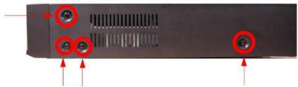
natural_image
Back panel of a computer drive showing two red circular buttons and mounting points (no text or symbols visible)Appendix J: Replacing the Hard Drive
- Carefully slide the cover away from the front panel and lift away from the housing. NOTE: Make sure the cover is clear of all ports and connectors on the rear panel.

text_image
Slide cover- Disconnect the SATA data and power cable from the hard drive. To remove the SATA data cable, pinch the metal connector, and gently pull.

natural_image
Close-up of an electronic device showing internal components and wiring, with no visible text or symbols.Appendix J: Replacing the Hard Drive
- Remove the four (4) screws on the side of the hard drive housing. Repeat for the other side.
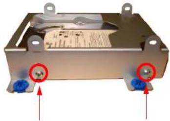
natural_image
Exterior view of a metallic electronic device with two blue ports and red circular annotations (no readable text or symbols)- Place the new hard drive in the housing, and secure with the 4 silver screws.
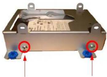
natural_image
Exterior view of a metallic electronic device with two blue ports and red circular annotations pointing to the ports (no readable text or symbols)Appendix J: Replacing the Hard Drive
- Connect the SATA power and data cables in the hard drive.
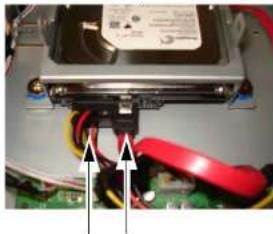
natural_image
Close-up of a hard disk drive with red and black clamps, showing wiring and mounting bracket (no visible text or symbols)You can install two hard drives on the hard drive housing. Simply mount the hard drive on the upper portion of the hard drive chassis using 4 screws (normally included with new hard drives).
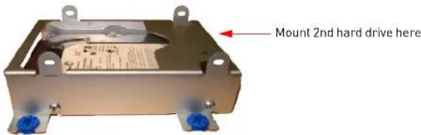
text_image
Mount 2nd hard drive hereConnecting two hard drives
Once the hard drive is mounted into the system, connect the two SATA power and data cable into the hard drives.
Appendix J: Replacing the Hard Drive
DH230: Installing 3 hard drives (8 & 16 channel only)
On the 8 & 16 channel models, you can install a maximum of three hard drives in the system if you remove the DVD/CD-RW drive. This is optional. Note that if you remove the optical drive, you will need to back up externally onto a USB device.
To remove the internal DVD/CD-RW drive:
- Remove the SATA power and data cable from the CD/DVDRW drive.
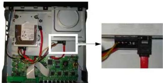
natural_image
Interior view of an electronic device showing a circuit board, wiring, and a close-up of a connector with red wires (no visible text or symbols)- Turn the unit over, and remove the three [3] screws that secure the CD/DVDRW drive. Place your hand underneath the DVD/CD-RW drive as you loosen the last screw to prevent the DVD/CD-RW drive from falling.
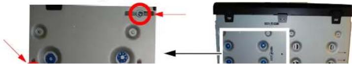
natural_image
Close-up of a device's front panel showing circular components and a magnified inset (no visible text or symbols)Appendix J: Replacing the Hard Drive
- Slide the DVD/CD-RW drive out the slot.

natural_image
Exterior view of a black and white electronic device labeled 'DIGIMERGE Touch' (no additional text or symbols visible)- Align the screw holes on the hard drive to the 4 blue rubber grommets. Ensure the SATA power and data connectors on the hard drive faces away from the front panel.
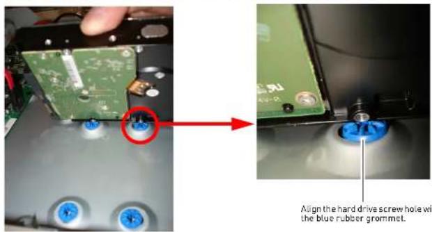
text_image
Align the hard drive screw hole with the blue rubber grommet.Appendix J: Replacing the Hard Drive
To remove the hard drive:
- Power off the system, and unplug all wiring / cabling from the system.
- Remove the four (2) short screws on the side panel is of the housing and the five (5) short screws on the rear panel. Keep these sets of screws separate.
ATTENTION: Do not remove the two screws near the fan on the side of the housing.
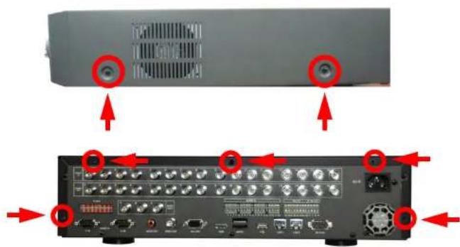
text_image
Diagram showing front and back views of a device with labeled ports and connectors, highlighting red arrows pointing to ports with labels like 'TENKON' and 'TENKON'.Appendix J: Replacing the Hard Drive
- Carefully slide the cover away from the front panel and lift away from the housing. NOTE: Make sure the cover is clear of all ports and connectors on the rear panel.
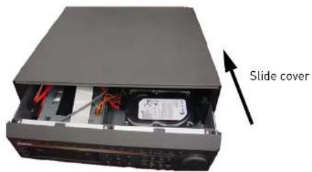
text_image
Slide cover- Disconnect the SATA data and power cable from the hard drive. To remove the SATA data cable, pinch the metal connector, and gently pull.
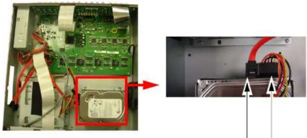
natural_image
Interior view of an electronic device showing a green circuit board with attached components and a close-up of the internal wiring (no visible text or symbols)Appendix J: Replacing the Hard Drive
- Remove the four (4) screws on the side of the hard drive housing. Repeat for the other side.
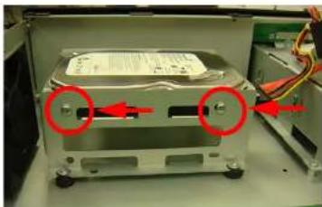
natural_image
Close-up of a metallic electronic device with red arrows pointing to two circular components, no visible text or symbols.- Place the new hard drive in the housing, and secure with the 4 silver screws.

natural_image
Close-up of a computer drive chassis with red arrows pointing to ports and cable (no visible text or symbols)Appendix J: Replacing the Hard Drive
- Connect the SATA power and data cables in the hard drive.
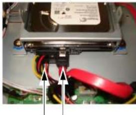
natural_image
Close-up of a hard disk drive with visible circuit board and wiring (no text or symbols)You can install up to four hard drives on the hard drive housing. Simply mount the hard drive on the lower portion of the hard drive chassis using 4 screws (normally included with new hard drives).

natural_image
Exterior view of a silver hard drive chassis with mounting holes and control panel (no visible text or symbols)Mount 2nd hard drive here
Appendix J: Replacing the Hard Drive
Formatting the Hard Drive
ATTENTION: Formatting the HDD erases all data on the hard disk. This step cannot be undone. System settings will not be erased.
- Press the MENU butt on on the front panel of the system.
- Click DISK→RECORD ING DISK.
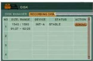
text_image
DISK DISK MANAGER RECRIDING DISK NO SIZE, RANGE DEVICE STATUS ACTION 154G / 159G INT-A STABLE REMOVE 01/27 - 02/25 2 3 4RECORDING DISK
- Beside the hard drive you wish to format, click the RE MOVE button.
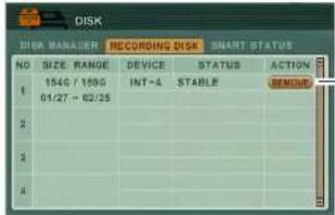
text_image
DISK DISK MANAGER RECORDING DISK SMART STATUS NO SIZE RANGE DEVICE STATUS ACTION 1 154G / 169G INT-A STABLE DENOU 01/27 - 02/25 2 3 4REMOVE button
Appendix K: Using Listen-in Audio
APPENDIX K: USING LISTEN-IN AUDIO
Listen-in audio allows you to listen to, and record live audio on the system.
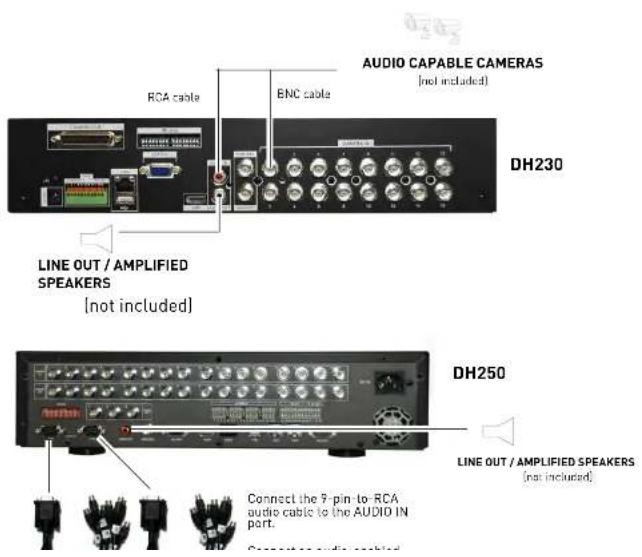
text_image
AUDIO CAPABLE CAMERAS (not included) RCA cable ENC cable DH230 LINE OUT / AMPLIFIED SPEAKERS (not included) DH250 LINE OUT / AMPLIFIED SPEAKERS (not included) Connect the 9-pin-to-RCA audio cable to the AUDIO IN port. Close-up audio cableAppendix K: Using Listen-in Audio
Playing AVI Files
If you selected for the converted file to open automatically, the file will open in your default media player. If not, click QUIT to close AVI Converter.
ATTENTION: An AVI media player such as VLC or DivX is required to playback AVI files. You can also installed the XviD, DivX, or ffdshow codecs to play the AVI files in Windows Media Player.
To playback AVI files:
- On your PC, open the folder where you saved the AVI file. By default, converted files use the following naming convention:
yyyy_mm_dd_hh_mm_ss_channel#_channel#_channel#_channel#.avi - Double-click the file to open in your default media player, or right-click to open the file with a AVI-compatible media player.
natural_image
Interior view of a wooden room with people interacting near a dog sculpture (no visible text or symbols)APPENDIX L: REMOTE VIEWING USING INTERNET EXPLORER
Along with the CMS-DH remote client software, you can also view your system remotely using Internet Explorer (version 7 or later recommended). Remote viewing through Internet Explorer allows for viewing from up to three simultaneous connections.
NOTE: Remote viewing is only compatible with Internet Explorer. Mozilla Firefox, Opera, Safari and other browsers are not supported.
To view your system using Internet Explorer:
- Open Internet Explorer.
- In the address bar, enter your system's IP address or your Digimerge DDNS domain followed by :80 — for example, http://192.168.1.1:80 or http://tomsmith.digimerge.net:80
NOTE: You MUST include http:// in order to access your system.
NOTE: If you need help finding your system's IP address, see "How Do I Find My IP and MAC addresses?" on page 139.
- Login with the user name admin, and your default system password, 000000.
- Click Install when the security warning appears. The page will refresh and live viewing will commence.
Click Install
Final Result

text_image
Live FEED 15:30:10 2 15:30:10 3 15:30:10 4 5:58:10 6 15:30:10 7 LOSSAppendix M: DH230/250 Series Touch Screen Monitor Setup
APPENDIX M: DH230/250 SERIES TOUCH SCREEN MONITOR SETUP

The USB cable must be connected to the monitor's USB port and the DVR's USB port to enable the touch screen function.
The DH230/250 Series DVRs can be controlled with a touch screen monitor (not included). Touch screen monitors must be Windows 7® Touch compatible to work with the system.
Step 1 of 3: Connect the Cables
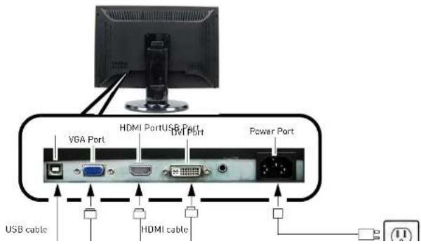
text_image
VGA Port HDMI PortUSB Port DVI Port Power Port USB cable HDMI cableStep 2 of 3: Power on the Monitor
Step 3 of 3: Test the Touch Screen Functions
Before you start:
- Make sure your monitor is turned on.
- Power on your DVR.
- Wait for the DVR to boot into the main viewing mode.
Access Virtual Remote
- While in viewing or playback mode, press and hold anywhere on the screen to access the Virtual Remote. For details, see "Using the Virtual Remote" on page 16. Tap outside the Virtual Remote to exit.
Navigate Menus
- While navigating menus, tap to select a menu option.
- Tap ← (ENTER) to save your changes and ✗ (EXIT) to exit menus without saving changes.
Select Channels

- While in a split-screen display mode, double-tap an individual channel to view it in full-screen. Double-tap again to return to split-screen display mode.
Reposition Channels
You can reposition the channels on the display screen. This can be very useful when monitoring a live location(s).
- Place the main display screen in either a quad display, or in a multi split-screen configuration.
NOTE: Repositioning will not work if the main display screen is in full-screen single channel.
- Dress and hold inside the channel you would like to move. Drop your fingers to the channel you
TROUBLESHOOTING
When a malfunction occurs, it may not be serious and can be corrected easily. The following describes the most common problems and solutions. Please refer to the following before calling Digimerge Technical Support:
| Error Possible Causes Solutions | ||
| • DVR is not receiving power, or is not powering up | • Cable from power adapter is loose or is unplugged | • Confirm that all cables are connected correctly• Confirm that the power adapter is securely connected to the back of the unit |
| • Cables are connected, but DVR unit is not receiving sufficient power | • Confirm that the unit is powered on ILED indicators on the front should be ON)• If the unit is connected through a power bar or surge protector, try bypassing the bar and connecting the power directly to the wall outlet• Confirm that there is power at the outlet:• Connecting the power cable to another outlet• Test the outlet with another plugged device (such as an electric calculator or phone charger) | |
| • Remote control is not detected by the system | • Batteries in the remote control are drained | • Install a fresh CR2025 battery in the remote control |
| • There are no batteries in the remote control | ||
| • Hard drive is not detected by the system | • Hard drive cables are loose or not properly connected• Hard drive bus out base | • Remove the housing and check that hard drive cables are firmly connected• For details are 3DU250. Descriptive the load |
Troubleshooting (cont'd.)
| Error Possible Causes Solutions | ||
| Mouse not detected by system | • Mouse cable is not firmly connected to the system | • Firmly connect the mouse cable to the PS/2 port on the side of the system; or connect a USB mouse to the top USB port on the rear panel of the system |
| • Mouse is not connected to the system | ||
| • System needs to be reset • Turn | the system OFF (press Power button on the front panel). Firmly connect a USB mouse to a USB port. Press the Power button again to turn the system ON | |
| • There is no picture on selected channels / camera picture is not being displayed | • Camera cables are loose or have become disconnected | • Check the camera video cable and connections• Disconnect and reconnect the cable at the DVR and at the Camera• Try moving the camera to another channel or use another cable |
| • The image on the DVR appears, but does not have sound | • Audio cables are loose or have been disconnected | • Check the AUDIO connections to the DVR |
| • Audio channel is set to OFF in the system menu | • Open Main Menu>DEVICE. Beside AUDIO RECORD, select the channel that you wish to assign audio recording to. Click ENTER to save your settings. | |
| • Audio is associated with the wrong video channel | • Audio is only available for channel 1—connect the audio capable camera to channel 1 to avoid confusion | |
| • I can't set the time on the DVR | • The system is recording • Stop all recording on the system before attempting to set the time—resume recording immediately after setting the time | |
| • My system does not | • Continuous recording may be done | • Press 44/● on the front panel, or ● on the |
- My custom does not
• Continuous recording maybe - Brace 44 / ● on the front panel or ● on the
Remote Connectivity Trouble Shooting
| Error Possible Causes Solutions | ||
| I cannot connect to the system using a DDNS URL | No internet connectionA DDNS account was not createdIncorrect DDNS URLDDNS not enabled on the system | Ensure the DVR is connected to a high speed internet connection.Ensure that you have created a DDNS account.Ensure that you type the URL in full ie: http://tomsmith.digimerge.net:80.Ensure there are no spelling errors in the URL.Include http://and the port number of your system in the URL.Ensure DDNS is enabled on your system. |
| I receive an error when I try to log in to the system | Incorrect user name and password | The default user name is: adminThe default password is: 000000Ensure that caps lock is disabled. The password and user name are case sensitive. |
DIGIMERGE
Right for Business
Need Help?
Please make sure to visit our website www.digimerge.com to receive product updates and information.
3 Easy Ways To Contact Us

natural_image
Two-panel image showing a man using a laptop and another person talking on the phone (no visible text or symbols)Online:
Product support is available 24/7 including
product info rm ation, user manuals, quick start
up gui de s and FAQ's at www.di gi merge.com
By Email:
Te ch ni cal support (for tec hn ical/installat io n is su es)
tech@digimerge.com

natural_image
Close-up of a smiling man wearing a headset, with another person blurred in the background (no visible text or symbols)DIG!MERGE
www.digimerge.com
Digimerge Digital Video Recorder (DVR) - 5/3/1 Year Limited Hardware Warranty
Warranty: Subject to the exclusions, limitations and exceptions. Digimerge warrants to the initial end-user purchaser that this hardware product is free from manufacturing defects in material and workmanship under normal use for a period of three (3) years from the documented date of purchase. Digimerge warrants the security certified Seagate SV35 Series Hard Disc Drive (HDD) for a period of (5) years from the documented date of purchase.
DVR Warranty Details:
The three (3) year warranty period consists of:
• One (1) year over-the-counter replacement warranty covering parts and labor
- Two (2) additional years of repair depot warranty covering parts and labor with proof of RA issued by Digimerge tech support
- Note: Return Authorization number (RA) must be issued by Digimerge Technical Support to the Dealer prior to product replacement at the Distributor.
Exceptions to the above warranty are:
- DVR components including, but not limited to, moving parts, motors, fans, removable flash memory. These are warranted for a one (1) year period.
• Data loss – end users are recommended to back up the content of the hard drive on a regular basis. - Data recovery, consequential damages, incidental damages and costs related to removal and installation of the hard drive are not covered under this warranty and are not part of the repair or exchange process.
Software & Consumables: All software, accompanying documentation and consumables (including but not limited to fuses and batteries) provided with or as part of the product are furnished AS IS, and are excluded from warranty coverage. Digimerge is not obligated to provide the end-user with a substitute product during the warranty period or at any time.
NOTE: Products are subject to continuous improvement. DIGIMERGE Technologies Inc. and its subsidiaries reserve the right to modify product design, specifications and prices, without notice and without incurring any obligation. Software and firmware are subject to updates from time to time.
For valid warranty claims made during the warranty period, upon proper proof of purchase (which is defined as a "valid form of a bill of sale or receipt from an authorized retailer or distributor showing the original date of purchase"), defective products will, at the sole discretion of Diglmerge, be repaired or replaced with equal or better product in terms of hardware features without charge if all the conditions set forth in this warranty are met. Any products repaired or replaced within the warranty period, shall be warranted by Diglmerge to the initial end-user purchaser for 90 days from the return shipment date, or the remainder of the warranty term, whichever is longer. Repairs are warranted for 90 days outside the original warranty period. Products and parts, at Diglmerge's sole discretion, may be replaced with new or refurbished items, and the products and parts replaced become the property of Diglmerge. Product returned to Diglmerge must be properly packaged in its original packaging (or packaging providing the product with protection equivalent to the original packaging) and sent, with the postage
DIGIMERGE
www.digimerge.com
DIGIMERGE MAKES NO CLAIMS OR WARRANTIES OF ANY KIND WHATSOEVER REGARDING THE PRODUCT'S ABILITY OR EFFECTIVENESS IN PREVENTING OR REDUCING THE RISK OF, OR DAMAGES RESULTING FROM, LOSS OR THEFT OF PROPERTY OR PERSONAL INJURY. THIS LIMITED WARRANTY IS IN LIEU OF ALL OTHER WARRANTIES, EXPRESS OR IMPLIED, INCLUDING, BUT NOT LIMITED TO, ANY IMPLIED WARRANTY OF MERCHANTABILITY OR FITNESS FOR A PARTICULAR USE OR PURPOSE. REPAIR OR REPLACEMENT AS PROVIDED UNDER THIS LIMITED WARRANTY IS THE EXCLUSIVE REMEDY OF THE PURCHASER. DIGIMERGE SHALL IN NO EVENT BE LIABLE FOR ANY SPECIAL, INDIRECT, INCIDENTAL, PUNITIVE, OR CONSEQUENTIAL DAMAGES OF ANY KIND OR CHARACTER, INCLUDING, WITHOUT LIMITATION, PERSONAL INJURY, LOSS OF REVENUE OR PROFITS, FAILURE TO REALIZE SAVINGS OR OTHER BENEFITS, OR CLAIMS AGAINST THE PURCHASER BY ANY THIRD PERSON, EVEN IF DIGIMERGE HAS BEEN ADVISED OF THE POSSIBILITY OF SUCH DAMAGES.
No claims or statements regarding the product, whether written or verbal, by salespeople, retailers, dealers or distributors, that are not contained in this limited warranty or in the owner's manual are authorized by Digimerge and do not modify or expand this warranty. Some countries, states, or provinces do not allow the exclusion or limitation of implied warranties or the limitation of incidental or consequential damages for certain products supplied to consumers or the limitation of liability for personal injury. To the extent that such restrictions on limitations apply to the products, the above limitations and exclusions may be limited in their application. In that case, when the implied warranties are not allowed to be excluded in their entirety, they will be limited to the duration of the applicable written warranty, and if damages may not be limited then the above limitations on damages apply, but only to the greatest extent permitted by local law.
Warranty and Non-Warranty Service:
Warranty service can be received by contacting your Digimerge dealer (during the warranty period). The dealer is required to first contact Digimerge Technical Support for assistance. In the event the problem cannot be resolved over the phone or via email, Digimerge will advise to return the product, at customer's expense, for repair or replacement. Upon receipt of the defective product, Digimerge will send a repaired or replacement product at Digimerge's expense to the customer. Dealer should send product to:
In United States:
Digimerge Returns
Schenker Logistics
2363 E. Perry Road
Suite 171, Dock Door 44
Plainfield, IN 46168
In Canada:
Specification Sheets
High Resolution 480 TV Lines

ion Series
Ultra High Resolution 540 TV Lines

acle Series
Echelon image sensor and mechanical IR Cut Filter cuts through darkness and delivers 480 TV lines of uncompromised video quality.

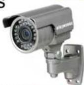
LEARN MORE
Looking for Installation?
Digimerge has the best network of professional
installers across North America.
READ MORE
BLUE HERE
(1)
-
广力云智慧零售收银系统
2.1.3 2017年
Dealers Click Here
To Join the Network

。
下表1-03
B=
-