M41164 - Security Camera FLIR - Free user manual and instructions
Find the device manual for free M41164 FLIR in PDF.

User questions about M41164 FLIR
0 question about this device. Answer the ones you know or ask your own.
Ask a new question about this device
Download the instructions for your Security Camera in PDF format for free! Find your manual M41164 - FLIR and take your electronic device back in hand. On this page are published all the documents necessary for the use of your device. M41164 by FLIR.
USER MANUAL M41164 FLIR
Instruction Manual M4100 Series
natural_image
Front view of a black OFLIR device with control buttons and indicator lights (no visible text or symbols on body)
Instruction Manual M4100 Series
Thank you for purchasing this product. FLIR Systems, Inc. is committed to providing our customers with a high quality, reliable security solution.
This manual refers to the following models:
M4104
M4108
M4116
For the latest online manual, downloads and product updates, and to learn about our complete line of accessory products, please visit our website at:
www.flir.com/security/pro

WARNING
RISK OF ELECTRIC SHOCK DO NOT OPEN

WARNING: TO REDUCE THE RISK OF ELECTRIC SHOCK DO NOT REMOVE COVER. NO USER SERVICEABLE PARTS INSIDE. REFER SERVICING TO QUALIFIED SERVICE PERSONNEL

The lightning flash with arrowhead symbol, within an equilateral triangle, is intended to alert the user to the presence of uninsulated "dangerous voltage" within the product's enclosure that may be of sufficient magnitude to constitute a risk of electric shock.

The exclamation point within an equilateral triangle is intended to alert the user to the presence of important operating and maintenance (servicing) instructions in the literature accompanying the appliance.
Table of contents
1 Important Safeguards ....1
1.1 General Precautions.... 1
1.2 Installation.... 1
1.3 Service 3
1.4 Use....3
2 Getting Started (M4100 Series) 4
3 Front Panel (M4100 Series)....5
4 Rear Panel (M4100 Series)....6
5 Basic Setup (M4100 Series) 8
5.1 Step 1: Connect the BNC Cameras....8
5.2 Step 2: Connect the Mouse....8
5.3 Step 3: Connect the Ethernet Cable ....8
5.4 Step 4: Connect the Monitor....9
5.5 Step 5: Connect the Power Adapter and Power on the DVR....9
5.6 Step 6: Upgrade Firmware to Latest Version (if Available) 9
5.7 Step 7: Verify Camera Image 10
5.8 Step 8: Set the Time 10
5.9 Default System Password & Port Numbers 10
5.9.1 FLIR Cloud™ 10
5.10 Quick Access to System Information 11
6 About MPX.... 12
6.1 What types of cabling and run lengths does MPX work with? 12
7 Remote Control 13
7.1 Setting the Remote Control Address 14
8 Using the System 15
8.1 On-Screen Display 15
8.2 Using the Quick Menu.... 16
8.3 Adjusting Color Settings 16
8.4 Using the Navigation Bar 17
8.5 Using the Camera Toolbar 17
Table of contents
12.4 Viewing Backup Files.... 31
12.4.1 Viewing Backup Files on PC 31
12.4.2 Viewing Backup Files on Mac 34
13 Managing Passwords and User Accounts.... 37
13.1 Changing Passwords.... 37
13.2 Adding Users 38
13.3 Modifying Users 39
13.4 Deleting Users 39
13.5 Account Groups 40
13.6 Adding Groups 40
13.7 Modifying Groups 41
13.8 Deleting Groups 41
14 Using the Main Menu 42
14.1 Camera 42
14.1.1 Recording.... 42
14.1.2 Configuring Recording Quality 43
14.1.3 Configuring Audio Recording 44
14.1.4 Configuring Snapshot Recording Settings.... 44
14.1.5 Creating Custom Channel Names.... 45
14.1.6 Selecting Cable Type 46
14.1.7 Upgrading Camera Firmware (Advanced) 46
14.2 Info 47
14.2.1 HDD Info 47
14.2.2 Record Info 48
14.2.3 Version 48
14.2.4 Alarm Status 48
14.2.5 Online Users 49
14.2.6 Load 50
14.2.7 Test.... 50
14.2.8 BPS 50
14.2.9 Log 51
Table of contents
14.3.19 Configuring General System Settings 66
14.3.20 Setting the Monitor Resolution (Display) 67
14.3.21 Configuring RS232 for a PTZ Keyboard.... 68
14.3.22 Saving Your System Configuration to a USB Thumb Drive 69
14.3.23 Setting the System to Factory Defaults.... 70
14.3.24 Upgrading Firmware from USB.... 71
14.4 Shutdown.... 73
15 Connecting to Your System Over the Internet on PC or Mac 74
15.1 System Requirements.... 74
15.2 Step 1 of 3: Connect your System to Your Router 74
15.3 Step 2 of 3: Obtain the system's Device ID....75
15.4 Step 3 of 3: Connect to the System Over the Internet 75
16 Using FLIR Cloud™ Client for PC or Mac 79
16.1 Home Page 79
16.2 Live View 79
16.2.1 Live View Controls 80
16.2.2 Opening Live View in Multiple Monitors 81
16.3 Controlling PTZ Cameras 82
16.3.1 PTZ Presets 83
16.3.2 PTZ Tours 84
16.3.3 PTZ Pattern 85
16.3.4 PTZ Scan 86
16.3.5 PTZ Pan 86
16.4 Playback 86
16.5 Playback Controls 88
16.6 Downloading Video to your Computer Hard Drive.... 89
16.7 Alarm 90
16.8 Log 91
16.9 E-map 92
16.10 Devices 94
Table of contents
17.1.7 Enabling Push Notifications 110
17.1.8 Using the Event List 112
17.1.9 Using Favorites.... 113
17.1.10 Using the E-Map 114
17.1.11 Device Manager.... 116
17.1.12 Adding Devices Using an IP or DDNS Address (Advanced) 117
17.2 iPad 119
17.2.1 Prerequisites.... 119
17.2.2 Connecting to your system on an iPad 119
17.2.3 Live View Interface 120
17.2.4 Controlling PTZ Cameras.... 121
17.2.5 Using Playback Mode on iPad.... 122
17.2.6 Using Local File to View Manual Recordings 124
17.2.7 Enabling Push Notifications 125
17.2.8 Using the Event List 127
17.2.9 Using Favorites.... 128
17.2.10 Using the E-Map 129
17.2.11 Using the Device Manager 131
17.2.12 Adding Devices Using an IP or DDNS Address (Advanced) 131
17.3 Android 134
17.3.1 Prerequisites.... 134
17.3.2 Connecting to your System on Android 134
17.3.3 Live View Interface 135
17.3.4 Controlling PTZ Cameras.... 136
17.3.5 Viewing Snapshots and Videos with Local Files 137
17.3.6 Using Playback Mode on Android 137
17.3.7 Enabling Push Notifications 139
17.3.8 Using the Event List 140
17.3.9 Using Favorites.... 140
17.3.10 Using the E-Map 142
Table of contents
| 20.2.1 Presets | 160 |
| 20.2.2 Tours | 160 |
| 20.2.3 Pattern | 161 |
| 20.2.4 Auto Scan | 161 |
| 21 M4100 Series Hard Drive Installation | 163 |
| 21.1 Installing a Hard Drive | 163 |
| 21.2 Removing the Hard Drive | 164 |
| 21.3 Formatting Hard Drives | 165 |
| 22 Troubleshooting | 167 |
| 23 M4100 Series System Specifications | 169 |
| 24 Notices | 172 |
| 24.1 FCC/IC Notice | 172 |
| 24.2 Modification | 172 |
| 24.3 ROHS | 172 |
Important Safeguards
In addition to the careful attention devoted to quality standards in the manufacturing process of your product, safety is a major factor in the design of every instrument. However, safety is your responsibility too. This sheet lists important information that will help to ensure your enjoyment and proper use of the product and accessory equipment. Please read them carefully before operating and using your product.
1.1 General Precautions
- All warnings and instructions in this manual should be followed.
- Remove the plug from the outlet before cleaning. Do not use liquid aerosol detergents. Use a water-dampened cloth for cleaning.
- Do not use this product in humid or wet places.
- Keep enough space around the product for ventilation. Slots and openings in the storage cabinet should not be blocked.
- It is highly recommended to connect the product to a surge protector to protect from damage caused by electrical surges. It is also recommended to connect the product to an uninterruptible power supply (UPS), which has an internal battery that will keep the product running in the event of a power outage.

CAUTION
Maintain electrical safety. Power line operated equipment or accessories connected to this product should bear the UL listing mark or CSA certification mark on the accessory itself and should not be modified so as to defeat the safety features. This will help avoid any potential hazard from electrical shock or fire. If in doubt, contact qualified service personnel.
1.2 Installation
- Read and Follow Instructions: All the safety and operating instructions should be read before the product is operated. Follow all operating instructions.
- Retain Instructions: The safety and operating instructions should be retained for future reference.
- Heed Warnings: Comply with all warnings on the product and in the operating instructions.
-
Polarization: Do not defeat the safety purpose of the polarized or grounding-type plug. A polarized plug has two blades with one wider than the other.
-
Power Sources: This product should be operated only from the type of power source indicated on the marking label. If you are not sure of the type of power supplied to you, location, consult your video dealer or local power company. For products intended to operate from battery power, or other sources, refer to the operating instructions.
- Overloading: Do not overload wall outlets or extension cords as this can result in the risk of fire or electric shock. Overloaded AC outlets, extension cords, frayed power cords, damaged or cracked wire insulation, and broken plugs are dangerous. They may result in a shock or fire hazard. Periodically examine the cord, and if its appearance indicates damage or deteriorated insulation, have it replaced by your service technician.
- Power-Cord Protection: Power supply cords should be routed so that they are not likely to be walked on or pinched by items placed upon or against them. Pay particular attention to cords at plugs, convenience receptacles, and the point where they exit from the product.
- Surge Protectors: It is highly recommended that the product be connected to a surge protector. Doing so will protect the product from damage caused by power surges. Surge protectors should bear the UL listing mark or CSA certification mark.
- Uninterruptible Power Supplies (UPS): Because this product is designed for continuous, 24/7 operation, it is recommended that you connect the product to an uninterruptible power supply. An uninterruptible power supply has an Internal battery that will keep the product running in the event of a power outage. Uninterruptible power supplies should bear the UL listing mark or CSA certification mark.
- Ventilation: Slots and openings in the case are provided for ventilation to ensure reliable operation of the product and to protect it from overheating. These openings must not be blocked or covered. The openings should never be blocked by placing the product on a bed, sofa, rug, or other similar surface. This product should never be placed near or over a radiator or heat register. This product should not be placed in a built-in installation such as a bookcase or rack unless proper ventilation is provided and the product manufacturer's instructions have been followed.
- Attachments: Do not use attachments unless recommended by the product manufacturer as they may cause a hazard.
-
Water and Moisture: Do not use this product near water — for example, near a bath tub, wash bowl, kitchen sink or laundry tub, in a wet basement, near a swimming pool and the like.
-
Camera Installation: Cameras are not intended for submersion in water. Not all cameras can be installed outdoors. Check your camera environmental rating to confirm if they can be installed outdoors. When installing cameras outdoors, installation in a sheltered area is required.
1.3 Service
- Servicing: Do not attempt to service this product yourself, as opening or removing covers may expose you to dangerous voltage or other hazards. Refer all servicing to qualified service personnel.
-
Conditions Requiring Service: Unplug this product from the wall outlet and refer servicing to qualified service personnel under the following conditions:
-
When the power supply cord or plug is damaged.
- If liquid has been spilled or objects have fallen into the product.
- If the product has been exposed to rain or water.
- If the product has been dropped or the cabinet has been damaged
- If the product does not operate normally by following the operating instructions. Adjust only those controls that are covered by the operating instructions. Improper adjustment of other controls may result in damage and will often require extensive work by a qualified technician to restore the product to its normal operation.
-
When the product exhibits a distinct change in performance. This indicates a need for service.
-
Replacement Parts: When replacement parts are required, have the service technician verify that the replacements used have the same safety characteristics as the original parts. Use of replacements specified by the product manufacturer can prevent fire, electric shock, or other hazards.
-
Safety Check: Upon completion of any service or repairs to this product, ask the service technician to perform safety checks recommended by the manufacturer to determine that the product is in safe operating condition.
1.4 Use
- Cleaning: Unplug the product from the wall outlet before cleaning. Do not use liquid cleaners or aerosol cleaners. Use a damp cloth for cleaning.
Getting Started (M4100 Series)
The system comes with the following components:
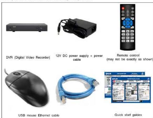
Hard drive size, number of channels, and camera configuration may vary by model. Please refer to your package for specific details. Check your package to confirm that you have received the complete system, including all components shown above.
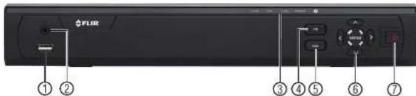
Front Panel (M4100 Series)
text_image
FLIR ① ② ③ ④ ⑤ ⑥ ⑦-
USB port: Connect a USB mouse (included) or connect a USB flash drive (not included) for data backup or firmware upgrades.
-
IR: Not supported
-
IR receiver and LED indicators: IR receiver for the remote control. Keep the IR receiver clear from obstructions.
• ALARM: Not supported.
- NET: Glows when network is in normal state. Turns off when there is a network error
- HDD: Glows to indicate hard drive is in normal state. Turns off when there is a hard drive error.
• POWER: Glows to indicate the system is on.
-
FN: Performs special functions in some menus.
-
ESC: In menus, press to go back / exit menus. In playback, press to return to live view
-
Directional buttons:
-
ENTER: From live view, press once to open the System Information screen. In menus, press to confirm menu options.
-
Directional buttons: Press to move cursor in menus. In live view, press up to change split screen layout; press left / right to select channels when single-channel mode is selected.
-
Power button: Press and hold to power off the system (system password required). Press to power the system back on.
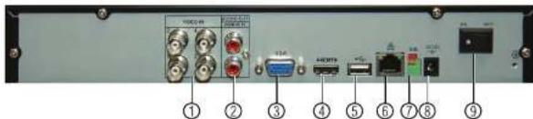
Rear Panel (M4100 Series)
4-Channel
text_image
Back panel of a network equipment or audio device with labeled ports and connectors8-Channel
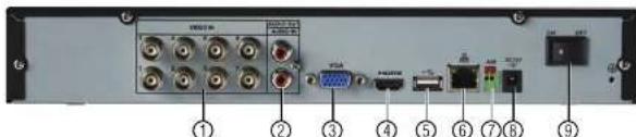
text_image
Back panel of a network equipment or device with labeled ports and connectors, numbered 1 to 9.- Video input: Connect FLIR MPX or standard analog cameras to the system.
- Audio IN/Audio OUT: RCA input and output for 1-channel audio recording.
- VGA: Connect a VGA monitor (not included) to view the system interface.
- HDMI: Connect to an HDMI monitor or TV (not included) to view the system interface.
- USB port(s): Connect a USB mouse (included) or USB flash drive (not included) for
data backup or firmware updates. - LAN: Connect a CAT 5 RJ45 Ethernet cable for local and remote connectivity.
- A/B: Connect RS485 cables.

NOTE
For full details on connecting PTZ cameras, see 20 Connecting a PTZ Camera (M4100 Series 158 for details.
page
-
DC12V: Connect the included power adapter.
-
ON/OFF switch: Turns the DVD on or off
-
USB port(s): Connect a USB mouse (included) or USB flash drive (not included) for data backup or firmware updates.
- HDMI: Connect to an HDMI monitor or TV (not included) to view the system interface.
- Audio IN/Audio OUT: RCA input and output for 1-channel audio recording.
- Video input: Connect FLIR MPX or standard analog cameras.
Basic Setup (M4100 Series)

NOTE
DVR back panels shown below are representative. Your DVR model may appear slightly different with all the same ports in different locations.
5.1 Step 1: Connect the BNC Cameras
- Connect FLIR MPX or standard analog cameras to the Video Input ports on the rear panel of the DVR.

natural_image
Back panel of a network equipment unit showing ports, connectors, and external components (no readable text or symbols)Push and twist the BNC connector clockwise to secure it to the BNC port.
5.2 Step 2: Connect the Mouse
- Connect a USB mouse (included) to one of the USB ports.
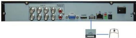
natural_image
Back panel of a network equipment unit showing ports, connectors, and a USB drive (no visible text or symbols)5.4 Step 4: Connect the Monitor
- Connect the included HDMI cable from the HDMI port to the TV or monitor (recommended).
OR
- Connect a VGA cable (not included) from the VGA port to the monitor.

text_image
VGA VGA VGA ① ②- VGA port.
- HDMI port.
5.5 Step 5: Connect the Power Adapter and Power on the DVR
- Connect the included power adapter to the DC 12V port. Connect the end of the power
- Turn the power switch to ON to turn on the DVR.
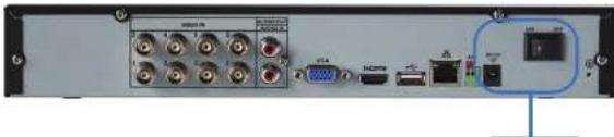
text_image
Back panel of a network equipment module showing ports, connectors, and a highlighted device with Chinese label.- Enter the system user name (default: admin) and password (default: 000000) and click OK. Wait for the firmware update to complete. The system will restart once the firmware has been upgraded.

text_image
WARNING DO NOT POWER OFF THE SYSTEM OR DISCONNECT THE POWER CABLE DURING FIRM WARE INSTALLATION5.7 Step 7: Verify Camera Image
- Power on the cameras, and then verify the camera video quality before mounting the cameras to a permanent location.
- Mount the cameras under a sheltered location. Always verify the outdoor rating of your camera before installing it in a permanent location.
5.8 Step 8: Set the Time
- Set the system time and date for accurate video time stamps. Videos with inaccurate times may not be valid as surveillance evidence.
- For details on setting the system time, see 9 Setting The Time, page 20.
5.9 Default System Password & Port Numbers

A user name and password is required to log in to the system. After logging on using a computer or mobile device the first time, you will be asked to create a custom password for the system.
Local system and remote connectivity (LAN & Internet) user name and password:
- Username: admin
- Password: 000000
5.10 Quick Access to System Information
To quickly open a window that displays vital system information:
- Right-click to open the Quick Menu and click Info. Enter the system user name (default: admin) and password (default: 000000). OR
- Press the ENTER button on the front panel. OR
- Press the ENTER button on the remote control.
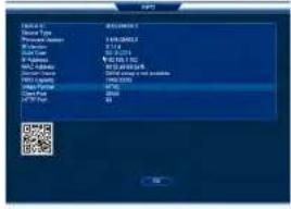
text_image
R.Q.10 C:\Program Files\Microsoft Office\ C:\Program Files\Microsoft Office\ C:\Program Files\Microsoft Office\ C:\Program Files\Microsoft Office\ C:\Program Files\Microsoft Office\ C:\Program Files\Microsoft Office\ C:\Program Files\Microsoft Office\ C:\Program Files\Microsoft Office\ C:\Program Files\Microsoft Office\ C:\Program Files\Microsoft Office\ C:\Program Files\Microsoft Office\ C:\Program Files\Microsoft Office\ C:\Program Files\Microsoft Office\ C:\Program File\Microsoft Office\ C:\Program File\Microsoft Office\ C:\Program File\Microsoft Office\ C:\Program File\Microsoft Office\ C:\Program File\Microsoft Office\ C:\Program File\Microsoft Office\ C:\Program File\Microsoft Office\ C:\Program File\Microsoft Office\ C:\Program File\Microsoft Office\ C:\Program File\Microsoft Office\ C:\Program File\Microsoft Office\ C:\Program File\Microsoft Office\ C:\Program File\Microsoft Office/ C:\Program File\Microsoft Office/ C:\Program File\Microsoft Office/ C:\Program File\Microsoft Office/ C:\Program File\Microsoft Office/ C:\Program File\Microsoft Office/ C:\Program File\Microsoft Office/ C:\Program File\Microsoft Office/ C:\Program File\Microsoft Office/ C:\Program File\Microsoft Office/ C:\Program File\Microsoft Office/ C:\Program File\Microsoft Office/ C:\Program File\Microsoft Office/ C:\Program F2456-0000 C:\Program F2456-0000 C:\Program F2456-0000 C:\Program F2456-0000 C:\Program F2456-0000 C:\Program F2456-0000 C:\Program F2456-0000 C:\Program F2456-0000 C: 13 OK
NOTE
The QR code shown in the System Info screen can be scanned during mobile setup to enter the system's Device ID.
About MPX
FLIR MPXTM is a revolutionary video surveillance format powered by HD-CVI technology. MPX delivers megapixel picture quality over coax, meaning you can upgrade your existing analog systems to HD resolution (1MP & 2.1MP) over a single coax cable (RG59 & RG6 compatible).
| NOTE |
| The DVRs covered in this manual are compatible with 1MP (720p), 2MP (1080p) and standard an cameras. |
6.1 What types of cabling and run lengths does MPX work with?
MPX allows a maximum cable run of up to 2300ft (700m) @ 720p or up to 2000ft (610m) @ 1080p, depending on the type of cable used (see below). It is required that the cable runs be made in a single run between camera and DVR, as daisychaining multiple cable runs together can prevent the DVR from getting a picture from the camera or may impact image quality. MPX supports standard UTP baluns for use with CAT5E or CAT6 cabling in your installation. The baluns should have a 12V and BNC connection at both ends. You can run up to 300ft (91m) per segment of CAT5E or CAT6.
| Cable Type Maximum Run Length | |
| RG59 20AWG Conductor 95% Braid CSA/UL or (UL) approved | 720p: Up to 1500ft (455m)1080p: Up to 1000ft (300m) |
| RG6 20AWG Conductor 95% Braid CSA/UL or (UL) approved | 720p: Up to 2300ft (700m)1080p: Up to 2000ft (600m) |
| Analog CCTV Balun 720p: Up to 300ft (91m) | 1080p: Up to 300ft (91m) |
Remote Control
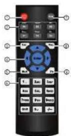
- Power: Press and hold to power off the system. Press to power on.
-
Playback controls:
-
Pause/Play: In live view, press to enter playback mode. Press to play/pause playback.
• Reverse: Press to reverse playback/pause playback.
• Fast: Press to increase playback speed.
• Next: Press to skip to next video.
• Previous: Press to skip to previous video. -
Slow: Press for slow playback.
-
Esc: In menus, press to go back / exit menus. In playback, press to return to live view.
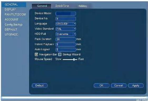
7.1 Setting the Remote Control Address
If you have more than one system, you can set up your remote control to pair with a specific system.
To set the remote control address:
- Right-click and click Main Menu. Enter the system user name (default: admin) and password (default: 000000).
- Click X and then click Setting>General>General.
- Under Device No., enter the address number you would like to assign to the remote control.
text_image
GENERAL DISPLAY PANTLETZOOM ACCOUNT Config Backup DEFAULT UPGRADE General Date&Time Holiday Device Model: Device No: 8 Language ENGLISH- Video Standard PAL HDD Full Overwrite Pack Duration 30 min. Instant Playback 5 min Auto Logout 5 min Navigation Bar Setup Wizard Mouse Speed Slow Fast Default OK Cancel ApplyUsing the System
Use the system's graphical on-screen display to navigate menus and configure options and settings.
8.1 On-Screen Display
The system shows the following for all display views:
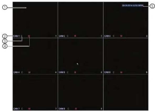
text_image
03-25-2014 03:32:00PM ① ② CAM 1 C M 1 CAM 2 C M 2 CAM 3 C M 3 ③ ④ CAM 4 C M 4 CAM 5 C M 4 CAM 6 C M 5 CAM 7 C M 7 CAM 8 C M 81. Display area:
- Double-click on a channel to view in full-screen; double-click again to return to split screen.
8.2 Using the Quick Menu
The Quick menu gives you access to the system's key functions. To access the Quick Menu, right-click the screen during live view.
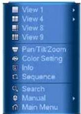
The Quick Menu has the following options:
- View: Select a camera in full-screen or select a multi-channel display.
- Pan/Tilt/Zoom: Access controls for PTZ cameras (not included).
• Color Setting: Configure color settings for cameras. - Info: Opens the system information window.
- Sequence: Click to start/stop sequence mode.
- In sequence mode, the system will automatically cycle through connected cameras every few seconds.
- A will appear to show that sequence mode is on.
- Click the icon to pause sequence mode on the channel that is currently shown (icon changes to 📄). Click again to resume sequence mode.
-
Right click and select Sequence to return to normal viewing mode
-
Adjust the Hue, Brightness, Contrast, and Saturation settings that the camera will use. To enable custom Gain controls, check Gain and use the slider to configure the gain level.
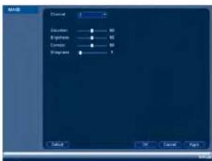
text_image
Gradient Duration Brightness Constant Smoothness 0 OK Cancel Help- Click OK to save changes.
8.4 Using the Navigation Bar
The Navigation Bar gives quick access to certain functions and menus.
To open the Navigation bar:
- Left click on the screen to open the Navigation Bar. The Navigation Bar has the following options:
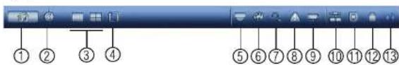
text_image
Screenshot of a software toolbar with numbered icons pointing to various function keys or buttons.- Main Menu.
- Collapse.
- Select display layout
To access the Camera Toolbar:
- Move the mouse to the top of the channel display. The Camera Toolbar has the following options:

text_image
① ② ③ ④ ⑤- Quick Playback
- Digital zoom
- Real-time backup
- Snapshot
- Mute/unmute audio
8.5.1 Using Quick Playback
Quick Playback is used to playback the last 5–60 minutes of video from the selected channel. You can also access Quick Playback in split-screen mode, while still viewing live video from the other channels.
To use Quick Playback:
- Move your mouse to the top of the channel display and click

NOTE
By default, the system will begin playback from 5 minutes ago. You can increase this to up to 60 minutes using the Realtime Play setting in Main Menu>Setting>General.
- Right-click to exit Quick Playback.
8.5.2 Using Digital Zoom in Live Display
To use Real-time Backup:
- Insert the USB thumb drive or external hard drive into one of the USB ports on the system.
- Move your mouse to the top of the channel display and click to start Real-time Backup.
- Click again to end Real-time Backup. The file is saved to your USB device.

text_image
NOTE If the system prompts you to log in, you will need to back again to start Real-time Backup after logging in.8.6 Using the Virtual Keyboard
The Virtual Keyboard is used to input text or numeric values in certain menus.

text_image
1 ? @ # $ % ^ & ' - _ ← 1 2 3 q w e r l y u i o p / 4 5 6 a s d l g h j k l : Enter 7 8 9 z x c v b n m . Shift ↩ 0 ← ① ② ③- Backspace.
- Enter capital letters.
- Confirm entry.
Setting The Time

CAUTION
It is highly recommended to set the date and time when first setting up your system. Inaccurate time stamps may render your footage unusable for court evidence.
To set the date and time:
- In the main viewing mode, right-click and click Main Menu.
-
Log in using the system user name (default: admin) and password (default: 000000).
-
Click

and select Setting. Click General and select the Date&Time tab.
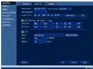
text_image
GENERAL General Data Time Holiday D:\Program Files\Out Settings\Out Time Data Time: 00:00:00 Data Time: 01:00:00 Data Time: 02:00:00 Data Time: 03:00:00 Data Time: 04:00:00 Data Time: 05:00:00 Data Time: 06:00:00 Data Time: 07:00:00 Data Time: 08:00:00 Data Time: 09:00:00 Data Time: 10:00:00 Data Time: 11:00:00 Data Time: 12:00:00 Data Time: 13:00:00 Data Time: 14:00:00 Data Time: 15:00:00 Data Time: 16:00:00 Data Time: 17:00:00 Data Time: 18:00:00 Data Time: 19:00:00 Data Time: 20:00:00 Data Time: 21:00:00 Data Time: 22:00:00 Data Time: 23:00:00 Data Time: 24:00:00 Data Time: 25:00:00 Data Time: 26:00:00 Data Time: 27:00:00 Data Time: 28:00:00 Data Time: 29:00:00 Data Time: 30:00:00 Data Time: 31:00:00 Data Time: 32:00:00 Data Time: 33:00:00 Data Time: 34:00:00 Data Time: 35:00:00 Data Time: 36:00:00 Data Time: 37:00:00 Data Time: 38:00:00 Data Time: 39:00:00 Data Time: 40:00:00 Data Time: 41:00:00 Data Time: 42:00:00 Data Time: 43:00:00 Data Time: 44:00:00 Data Time: 45:00:00 Data Time: 46:00:00 Data Time: 47:00:00 Data Time: 48:00:00 Data Time: 49:00:00 Data Time: 50:00:00 Data Time: 51:00:00 Data Time: 52:00:00 Data Time: 53:00:00 Data Time: 54:00:00 Data Time: 55:00:00 Data Time: 56:00:00 Data Time: 57:00:00 Data Time: 58:00:00 Data Time: 59:00:00 Data Time: 60:00:00 Data Time: 61:00:00 Data Time: 62:00:00 Data Time: 63:00:00 Data Time: 64:00:00 Data Time: 65:00:00 Data Time: 66:01.1.1.2.3.4.5.6.7.8.9.1.1.2.3.4.5.6.7.8.9.1.1.2.3.4.5.6.7.8.9.1.1.2.3.4.5.6.7.8.9.1.1.2.3.4.5.6.7.8.9.1.1.2.3.4.5.6.7.8.- Under System Time, enter the current time and select your time zone. Then, click OK.
- Check the DSTcheck box to enable auto Daylight Savings Time updates.

NOTE
- You can adjust the Start Time and End Time for Daylights Savings Time if the default settings do not match your region.
- Under DST Type, select Week to set the start and end time based on a day and week (e.g. 2nd Sunday in March), or select Date to set the start and end time to a specific date.
Recording
By default, the system is set to immediately record video from connected cameras continuously, 24 hours a day. You can customize the recording settings according to your needs.
10.1 Video Recording Types
The system supports the following recording types.
- Recording—Continuous: Normal, continuous recording. A C icon is shown when recording is in progress.
- Recording—Motion: The system records when motion is detected by the camera. An icon is shown when motion is detected.
10.2 Main Stream and Sub Stream
The system employs two video recording streams, a Main Stream and a Sub Stream. Both Main Stream and Sub Stream recording are enabled by default.
The Main Stream records high quality video to your system's hard drive.
The Sub Stream records lower resolution video for efficient streaming to devices over the Internet. Sub Stream recording must be enabled to view video recordings on a computer or mobile device.
You can configure the video quality parameters for the Main Stream or Sub Stream. For details, see 14.1.2 Configuring Recording Quality, page 43.
10.3 Setting up Scheduled or Manual Recording
You can set the system to record based on a schedule or you can manually turn recording on and off. By default, the system is set to record on an always on recording schedule.
To configure the recording schedule, see 14.3.13 Configuring the Video Recording Schedule, page 62.
To select between scheduled and manual recording:
- Right-click and then select Manual>Record.
Recording10
-
Under Main Stream, select how the system will record the Main Stream for each channel.
-
Schedule: Main Stream Recording will follow the recording schedule.
- Manual: The system will record the Main Stream continuously as long as this option is checked.
-
Stop: The system will not record the Main Stream for this channel. This option is not recommended.
-
Under Sub Stream, select how the system will record the Sub Stream for each channel.
-
Schedule: Sub Stream Recording will follow the recording schedule.
- Manual: The system will record the Sub Stream continuously as long as this option is checked.
-
Stop: The system will not record the Sub Stream for this channel.
-
Under Snapshot, select Enable to enable snapshot recording on each channel. Or, select Disable to disable snapshot recording.
- Click OK to save changes.
10.4 Configuring Hard Drive Overwrite
When the hard drive is full, the system will overwrite the oldest recordings by default. This is recommended, as it makes sure that your system will continue to record without any input from you. You can also set the system to stop recording once the hard drive is full.
To configure hard drive overwrite:
-
Right-click and select Main Menu. Click > Setting>General>General.
-
Under HDD Full, select Overwrite for the system to overwrite the oldest recordings when the hard drive is full. Or, select Stop Record for the system to stop recording when the hard drive is full.

Recording10
- Click OK to save changes.
Search (Playback)
Search mode is used to navigate and playback recorded video files on the system.
11.1 Playing Back Video from the Hard Drive
- From live view, right-click and then click Search.
- Log in using the system user name (default: admin) and password (default: 000000).
- Configure the following:

text_image
From Read/Write HSD REC FIC 1 2 3 Step Synch AirRecord Continuous Alarm Motion Stop3.1. Use the calendar on the right to select the day to playback.
3.2. Use the drop-down menus to select the channels you would like to playback.
11.2 Playback Controls

text_image
Screenshot of a CD/DVD audio workstation interface with numbered labels pointing to various track names and playback controls.- Select playback device.
- Calendar: Select the day to playback.
- Channel select: Select channels to playback.
- Video clip backup: Select video clip start and end times.
- Backup video clip: Click to save selected clip.
- Playback Bar: Click inside the bar to select a playback time.
- Zoom Playback Bar: Select scope of time bar
- Recording types: Click to show/hide recording types.
- Speed up
-
Slow
-
Click From ReadWrite Hdd and select From IO Device. Click Browse to open the USB drive and manually select the video file.

text_image
File Edit View Help Add 2 Options Delete Remove Edit View Paste View Paste- Double click the video file you would like to open.
11.4 Using Smart Search
Smart Search makes it easy to review motion events in specific zones of your video stream. Select the areas that interest you and Smart Search plays your recording from the time when your camera detects motion in those areas. To set up smart search:
- In the multiple-channel playback mode, double-click a channel and then click the
Smart Search Icon ( )
- To create a Smart Search zone, left-click and select the area that you want to detect motion.
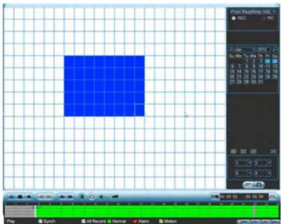
text_image
Point ReadWhite Help REC PC Zoom 2013 Su Me You We 25 P2 5x 6 7 8 9 10 11 12 13 14 15 16 17 18 19 20 21 22 23 24 25 26 27 28 29 30 31 0 3 3 4 Play Synch All Record Normal Alarm Motion-
Repeat these steps for each channel that you want to use Smart Search.
-
Click to start the Smart Search playback. To stop the Smart Search playback,
click again.
Backup
Backup video files to external USB flash drive (not included) or self-powered USB external hard drive (not included).

NOTE
USB external hard drives must be formatted in the FAT32 file format to be used with the system.
12.1 Formatting the USB Thumb Drive
It is recommended to format your USB thumb drive (not included) before using it with the system.

CAUTION
Formatting the USB device will permanently erase all data.
To format a USB device:
- Insert a USB thumb drive (not included) into one of the USB ports.
-
From live view, right-click and then select Main Menu. Login if prompted.
-
Click >Backup.
-
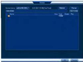
Select the USB device you would like to format under Device Name and click Browse.
text_image
Device Name: tdb1(USB DISK) 0.00 KB(Space Needed) 6.06 GB/7.23 GB(Free/Total) Type: All Start Time: 04 - 25 - 2014 12 : 00 : 00 AM Record Q= 1 End Time: 04 - 25 - 2014 11 : 25 : 48 AM File Format: DAV Add Remove 0 Channel Type Start Time End Time Size(MB)Backup12
- Click Format. Click OK to confirm.
text_image
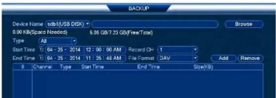
Name Description: S&P500 (SP5) 6.31 (0.21 GB/week Tsd) File Region Name Box Type: Open Box Folder Browse... Browse...12.2 Backing up Video
- Insert a USB thumb drive (not included) into one of the USB ports.
- From live view, right-click and then select Main Menu. Login if prompted.
- Click >Backup.
Backup12
- Configure your search options:
text_image
NET export File Edit (Show Number) Edit (Ctrl to Edit/Export Time) Type: All Start Time: 04:15 - 2016 12:30 07:40 Format: 1.0 End Time: 14:15 - 2016 11:30 07:40 The format: All Add Options Current Type Start Time End Time Settings Import- Select the USB device you would like to format under Device Name.
- Type: Select the recording type you would like to search for or select All to search all recording types.
- Record CH: Select the channel you would like to search or select All to search all channels.
- File Format: Select DAV to save files to .dav format. You can playback .dav files using the FLIR video player software. To find the video player visit www.flir.com/security/pro, search for the model number of your product, click on your product in the search results, and click on the Downloads tab. Or, select ASF for .asf format. You can playback .asf files in VLC Media Player (free download from www.videolan.org) on PC or Mac.

VLC Media Player is a free software available from www.videclan.org. VLC Media Player is not supported by FLIR.
- Start Time/End Time: Select the start and end time for your search.
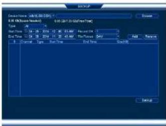
Backup12
- Click to mark the beginning of the video clip. Click to mark the end of the video clip.
- Click ☐ to open the Backup menu.
- Configure the following:

text_image
BACKUP 1 name(Type) Left Space/Total Space Device Status 1 USB1(USB DDR) 8.02 GB/7.23 GB Ready 9 CH Type Start Time End Time Size(KB) 1 C 05-05-14 10:15:12AM 05-05-14 10:21:46AM 2664 2 C 05-05-14 10:21:51AM 05-05-14 10:29:35AM 2877 3 C 05-05-14 10:28:58AM 05-05-14 10:35:23AM 640 4 C 05-05-14 10:34:54AM 05-05-14 10:38:46AM 722 5 C 05-05-14 11:35:48AM 05-05-14 11:39:48AM 403 6 C 05-05-14 11:36:24AM 05-05-14 11:38:26AM 384 7 C 05-05-14 11:39:31AM 05-05-14 11:40:06AM 384 8 C 05-05-14 11:41:08AM 05-05-14 11:43:06AM 386 9 C 05-05-14 12:09:05PM 05-05-14 12:09:06PM 384 Space Required / Space Remaining: 11.88 MB/6.32 GB Backup Remove5.1. Check the USB device where you would like to save the file.
5.2. Check the files you would like to backup.
5.2 Click Backup Then click Start Wait for the backup to complete before remov.
Backup12
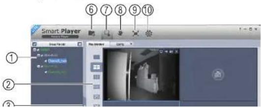
- Click to open a back up video file.

text_image
Smart Player My Video My Tools My Player My Video- Use the Player controls to control playback or select other files for playback.
Video Player Controls
text_image
Smart Player Play Streamer ① ② ③Backup12
- Display Area: Select the split-screen mode. Double-click a video file to expand. Click the controls inside the display area to do the following:
• View information about the video file.
• Start/stop a manual recording from the video file.
• Take a snapshot from the video file.
• X: Close the video file.
-
Hide/show file list.
-
Playback controls:
• Playback files in sequence.
• Synchronize playback times.
• Play/pause playback.
• : Stop playback.
•: Previous frame.
• Next frame.
• 1X : Playback speed.
• : Volume control.
-
Zoom Timeline.
-
Add Files: Click to open back up video files.
-
Digital Zoom: Click to activate digital zoom mode. Click and drag in the video to zoom
Backup12
- Config: Click to open the configuration menu for the player. From here you can control the default file formats and save locations for snapshots and video files saved from the player.

text_image
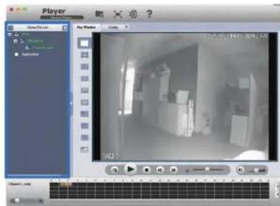
Smart Player Start End Target Start End Target Start End Target Start End12.4.2 Viewing Backup Files on Mac
You need a video player to play back .dav backup video files. To find the video player visi www.flir.com/security/pro, search for the model number of your product, click on your product in the search results, and click on the Downloads tab.
To view backup video files using the Player on Mac:
-
Download Video Player for Mac from www.flir.com/security/pro.
-
Double click the downloaded file in Safari to extract the Smart Player app file.

Backup12
- Click to open a back up video file in another location.
text_image
Player Game File List Play Window Control D401 Chassis.com- Use the Player controls to control playback or select other files for playback.
Video Player Controls
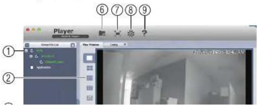
text_image
Player Edit List Play Window Control ① ② ⑥ ⑦ ⑧ ⑨Backup12
3. Hide/show file list.
4. Playback controls:
- When a video file ends, this button lets you select if you want the video player to repeat the same file or play the next file.
• Play/pause playback. - Stop playback.
•: Previous file.
• Next file.
• 1X : Playback speed.
• : Volume control.
5. Zoom Timeline.
- Add Files: Click to open back up video files.
- Full-screen: Click to open the player in full screen. Press ESC to exit full screen.
- Config: Click to open the configuration menu for the player. From here you can control the default file formats and save locations for snapshots and control the aspect ratio.

text_image
Player Name: 10.0000 Value/expense: -12 Language/loss (expense): Name:Managing Passwords and User Accounts
By default, the system user name is admin and the password is 000000. Passwords are enabled by default and are required to access the Main Menu or connect to the system using a computer or mobile device. You will be prompted to create a custom password after you connect for the first time.

NOTE
If you forget the password to the system, contact technical support to have it reset.
The system includes the following default accounts:
- admin: The admin account has full access to the system, may configure all system settings, and can manage user accounts.
- default: The default account is a limited user account that may only view live video from the cameras.
For security reasons, it is essential that you change the password on your system. By default, the system password is enabled.
13.1 Changing Passwords
You can change the system password of the admin and user accounts from the Users menu.
To modify an account password:
- From Live View, right-click and then select Main Menu.
-
If prompted, enter the system user name (default: admin) and password (default: 000000).
-
Click X and select Setting. Select Account.
-
Click next to the user account you would like to modify.
- Check Modify Password.
- Under Old Password, enter the account's previous password.
- Under New Password, enter a new 6 character password for the account. Repeat the new password under Confirm Password.
- Click OK to save changes.
13.2 Adding Users
You can allow multiple users to log in to the system. When adding different users, you can assign what menus they have access to. For example, you may want your friend to monitor your system while you are away, while not giving full access to your system.
To add a user account:
- From Live View, right-click and then select Main Menu.
-
If prompted, enter the system user name (default: admin) and password (default: 000000).
-
Click ✗ and select Setting. Select Account.
-
Click Add User.
5. Configure the following:

text_image
Add User User Name Password Mono Group admin Multiuser Confirm Password User MAC Authority System Playback Cover ALL ACCOUNT SYSTEM OFFLINE USER DEFAULT&UPGRADE PTZ NINFO MANUAL CONTROLBACKUP CAMERA SETTING STOURAGE EVENT NETWORK CAMERA CLEARLOG SHUTDOWN OK Cancel- User Name: Enter a name for the user account.
- Password: Enter a 6 character password for the user account. Enter the password again under Confirm Password.
- Memo (optional): Enter a description of the user account.
- Group: Select the group you would like to assign to this user account. A user account cannot be given permissions its group does not have.
- Multiuser: Check to enable this user account to be used to login from more than
Managing Passwords and User Accounts13
- Click OK to confirm.

NOTE
The admin and default user accounts cannot be deleted from the system.
13.5 Account Groups
Account groups can be used to easily manage permissions for multiple user accounts. User accounts can be given all the permissions of a group, but cannot be given permissions that the group does not have.
The system includes the following groups by default:
- admin: Accounts in the admin group are system administrators. They have full access
to the system, may configure all system settings, and can manage user accounts. - user: Accounts in the user group are normal users. They have limited access to system
13.6 Adding Groups
- From Live View, right-click and then select Main Menu.
- If prompted, enter the system user name (default: admin) and password (default: 000000).


-
Click and select Setting.
-
Click Account and select the Group tab.
-
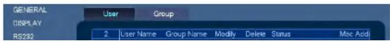
Click Add Group.

text_image
GENERAL DISPLAY RS232 PANTILT/ZOOM ACCOUNT Config Backup User Group 2 Group Name Modify Delete Memo 1 admin 2 user * * * administrator group * user groupManaging Passwords and User Accounts13
- Configure the following:
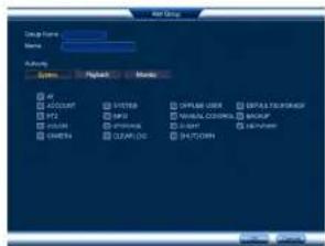
text_image
USB Group Design Form: Name: Access System Refresh Message CPU ACCOUNT SYSTEM OPRAM USER OFFSET/RESET FTP GPS LOCAL COLDEN BACKUP HKEYS OPTIONAL NETWORK CHANNEL CHANNEL• Under Group Name, enter a name for the group.
• Under Memo, enter an optional comment for this group.
- Under Authority, check the permissions that the group will have. User accounts assigned to this group can not be given any permissions the group does not have.
- Click OK to save changes.
13.7 Modifying Groups
- In the Group tab, click next to the group you would like to modify.
- Update the group's details as needed, and then click OK to save changes.
13.8 Deleting Groups
- In the Account menu, click next to the user account you would like to delete.
- Click OK to confirm.

NOTE
Using the Main Menu
To open the Main Menu:
- Using the Mouse: Right-click and click Main Menu.
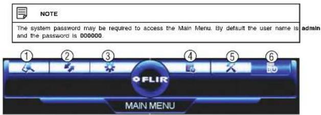
text_image
NOTE The system password may be required to access the Main Menu. By default the user name is admin and the password is 000000. ① ② ③ ④ ⑤ ⑥ FLIR MAIN MENU- SEARCH: Open Search/Playback mode. For details, see 11 Search (Playback), page 24.
- BACKUP: Export files to USB device. For details, see 12 Backup, page 28.
- CAMERA: Configure image settings, recording parameters, and titles for your cameras.
- INFO: View system information.
- SETTING: Configure general system, schedule, network, recording, display, and motion settings. Restore system to factory defaults.
- SHUTDOWN: Logout, restart, or shutdown the system.
14.1 Camera
The Camera menu allows you to configure image settings, recording parameters, and titles for your cameras.

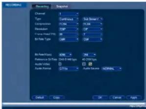
14.1.2 Configuring Recording Quality
The system employs two video recording streams, a Main Stream and a Sub Stream. The Main Stream records high quality video to your system's hard drive. The Sub Stream records lower resolution video for efficient streaming to devices over the Internet. You can customize the video quality settings for these streams according to your needs.
To configure recording quality:
-
From the Main Menu, click 🤐 and select Recording>Recording.
-
Select the camera you would like to configure.
-
Configure the following settings. Settings for the Main Stream are in the left column. Settings for the Sub Stream are in the right column.

text_image
RECORDING Accuracy Signal Channel: 0 Type: Continuous Sub-Stream/ Compression: 1764 1434 Precision: 7589 CIP Picture Color: RGB 1 Bitter Color: CMY CMY Air Quality: CMY 1764 Preference to Share: 20.0-340 bps 45.7999 bps Audio Value: Audio Format: QTYG Audio Value: NORMAL Default Copy Cancel Help- Type: For the Main Stream, you can set different recording quality settings for Continuous, MD (Motion Detect), and Alarm recording. Select the type of recording you would like to configure.
- Resolution: Select the resolution the selected camera will be recorded at. Higher resolutions create a more detailed image, but take up more hard drive space to record and require more bandwidth to stream to connected computers or mobile devices.
14.1.3 Configuring Audio Recording
The system supports one channel of audio recording.

NOTE
You must connect an RCA audio input device to the system to use audio recording or you must have an MPX camera that supports audio.
To configure audio recording:
- From the Main Menu, click ✿ and select Recording>Recording.
text_image
RECORDING Recording Snapshot Channel 1 Type Continuous Sub Stream/ Compression F: 264 F: 264 Phaseder TWP CIP Frame Preset P: 300 V Bit Rate Type GBT GB Bit Address: 4296 748 Reference Size Filter: 50-5400 bps 40-5000 bps Audio Video Audio Scale: 2716 Audio Scale NORMAL Default Copy On Cancel Apply- Under Channel, select 1.
- Check the left Audio/Video checkbox to enable audio recording. Check the middle checkbox to enable audio streaming to remote devices (such as a smartphone). Check the right checkbox to enable video streaming to remote devices.
- Under Audio Format, select the format that will be used to record audio. G711a is recommended.
- Under Audio Source, select Normal to use the system's RCA audio input.
- Click OK to save changes.
Using the Main Menu14
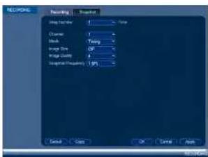
- Configure the following settings for snapshots saved automatically from motion detection or the snapshot schedule:
text_image
RECOPIED Recording Recorded Step Number 1 Name Character 1 Block 1 Size Size OFF Impact Type 2 Frequency 1.0% Serial Copy OK Cancel Apply- Channel: Select the channel you would like to configure.
- Mode: Select Timing for the system to take snapshots according to the snapshot schedule (see 14.3.15 Configuring the Snapshot Schedule, page 64) Select Trigger for the system to take snapshots only when triggered by motion detection (snapshot must be enabled in the Motion Detect menu (see 14.3.7 Configuring Motion Detection, page 55).
• Image Size: Select the resolution for snapshots.
• Image Quality: Select the snapshot image quality between 1 (lowest) and 6 (highest) -
Snapshot Frequency: Select the number of snapshots (up to 6) the system will take each time.
-
Click OK to save changes.
14.1.5 Creating Custom Channel Names
You can assign custom names to your cameras. For example, you can name your cameras based on their location (e.g. hallway or front door).
To create custom channel names:
Using the Main Menu14
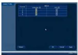
14.1.6 Selecting Cable Type
The Cable Type menu is used only if you are using cabling with a resistance higher than 10Ω per 100m (330ft) and you are having picture quality issues. Select the UTP option for any channels having the issue. In all other installations, use the Coaxial setting. Click OK to save your changes.
text_image
CALL TYPE Chase C:\Users\1000000000000000000000000000000000000000000000000000000000000000000000000000 1 2 3 4 RECA OK Cancel HelpTo manually upgrade camera firmware:
14.1.7 Upgrading Camera Firmware (Advanced)
Manually upgrade camera firmware with a .bin firmware file saved to a USB flash drive (not included). Typically, performing a manual camera firmware upgrade will not be necessary unless directed to do so by technical support.
Prerequisites:
- Connect a USB flash drive with a compatible .bin camera firmware file saved to it to one of the DVR's USB ports.
-
From the Main Menu, click and select MPX Upgrade.
-
Click Browse to search for and select the .bin camera firmware file.
Using the Main Menu14
14.2 Info
Info contains menus that show you system information.

text_image
INFO INFO ALARM STATUS NETWORK BPS LOG FLIR MAIN MENU14.2.1 HDD Info

text_image
F202 M-D RECEIVED NAME DATA: 1 AI Type Data Source New Type 1 Status 14.4.1.1 AI C:\M-MS D:\M-MSUsing the Main Menu14
14.2.2 Record Info

text_image
POSTS ERROR POSTS Start Time End Time POSTS 2001/12/2019 POSTS 2001/12/2019The Record Info menu shows the start and end times of recordings saved on the hard drive.
To access the Record Info menu:
- From the Main Menu, click 📄 and then select Info>Record Info.
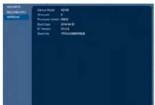
14.2.3 Version
text_image
DEMOH REQUIRED NPs WORCH Service Provider ICNB Provider P Pressure Provider 0015 Sub-Service 2014.01.28 W Provider 55.6.4 Data Port YU/ORDER/ORDERUsing the Main Menu14
text_image
File Name File Type File Name File Type File Description File Type Properties Properties Name: 10.0000000000000000000000000000000000000000000000000000000000000000000000000000000000000000000000000000 Name: 12.14.17.18 File Type: Normal Page 12.14.17.18 Page 12.14.17.19 Page 12.14.17.20 Page 12.14.17.21 Page 12.14.17.22 Page 12.14.17.23 Page 12.14.17.24 Page 12.14.17.25 Page 12.14.17.26 Page 12.14.17.27 Page 12.14.17.28 Page 12.14.17.29 Page 12.14.17.30 Page 12.14.17.31 Page 12.14.17.32 Page 12.14.17.33 Page 12.14.17.34 Page 12.14.17.35 Page 12.14.17.36 Page 12.14.17.37 Page 12.14.17.38 Page 12.14.17.39 Page 12.14.17.40 Page 12.14.17.41 Page 12.14.17.42 Page 12.14.17.43 Page 12.14.17.44 Page 12.14.17.45 Page 12.14.17.46 Page 12.14.17.47 Page 12.14.17.48 Page 12.14.17.49 Page 12.14.17.50 Page 12.14.17.51 Page 12.14.17.52 Page 12.14.17.53 Page 12.14.17.54 Page 12.14.17.55 Page 12.14.17.56 Page 12.14.17.57 Page 12.14.17.58 Page 12.14.17.59 Page 12.14.17.60 Page 12.14.17.61 Page 12.14.17.62 Page 12.14.17.63 Page 12.14.17.64 Page 12.14.17.65 Page 12.14.17.66 Page 12.14.17.67 Page 12.14.17.68 Page 12.14.17.69 Page 12.14.17.70 Page 12.14.17. Page 12, 2, 3, 4, 5, 6, 7, 8, 9, 10, 1, 2, 3, 4, 5, 6, 7, 8, 9, 10, 1, 2, 3, 4, 5, 6, 7, 8, 9, 10, 1, 2, 3, 4, 5, 6, 7, 8, 9, 10, 1, 2, 3The following alarms are shown in the Alarm Status menu:
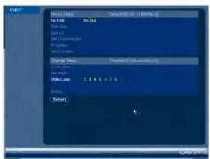
- No HDD: No hard drive is detected.
- Disk Error: Hard drive error detected.
- Disk Full: Hard drive is full.
- Net Disconnection: System is not connected to the network.
- IP Conflict: More than one device on the network is using the same IP address.
• MAC Conflict: More than one device on the network is using the same MAC address. - Local Alarm: Not supported.
- Net Alarm: Not supported.
• Video Loss: Shows disconnected channels. - Motion: Shows channels with active motion alarms.
To access the Alarm Status menu:
- From the Main Menu, click 📄 and then select Alarm Status.
14.2.5 Online Users

Using the Main Menu14
14.2.6 Load
text_image
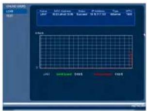
ONION USB LAN SAL/SLAM SAL/SLAM SAL/SLAM SAL/SLAM SAL/SLAM SAL/SLAM SAL/SLAM SAL/SLAM SAL/SLAM SAL/SLAM SAL/SLAM SAL/SLAM SAL/SLAM SAL/SLAM SAL/SLAM SAL/SLAM SAL/SLAM SAL/SAL/SLAM SAL/SAL/SLAM SAL/SAL/SLAM SAL/SAL/SLAM SAL/SAL/SLAM SAL/SAL/SLAM SAL/SAL/SLAM SAL/SAL/SLAM SAL/SAL/SLAM SAL/SAL/SLAM SAL/SAL/SLAM SAL/SAL/SLAM SAL/SAL/SLA SAL/SAL/SLA SAL/SAL/SLA SAL/SAL/SLA SAL/SAL/SLA SAL/SAL/SLA SAL/SAL/SLA SAL/SAL/SLA SAL/SAL/SLA SAL/SAL/SLA SAL/SAL/SLA SAL/SAL/SLA SAL/SAL/SLA SAL / S10 / S11 / S12 / S13 / S14 / S15 / S16 / S17 / S18 / S19 / S20 / S21 / S22 / S23 / S24 / S25 / S26 / S27 / S28 / S29 / S30 / S31 / S32 / S33 / S34 / S35 / S36 / S37 / S38 / S39 / S40 / S41 / S42 / S43 / S44 / S45 / S46 / S47 / S48 / S49 / S50 / S51 / S52 / S53 / S54 / S55 / S56 / S57 / S58 / S59 / S60 / S61 / S62 / S63 / S64 / S65 / S66 / S67 / S68 / S69 / S70 / S71 / S72 / S73 / S74 / S75 / S76 / S77 / S78 / S79 / S80 / S81 / S82 / S83 / S84 / S85 / S86 / S87 / S88 / S89 / S90 / S91 / S92 / S93 / S94 / S95 / S96 / S97 / S98 / S99 / S100The Load menu shows you the network traffic your system is sending and receiving.
To access Load:
- From the Main Menu, click E3 and then select Network>Load.
14.2.7 Test
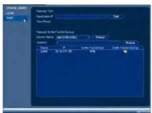
text_image
Timeout type Timeout Type Timeout Default Settings Timeout Name: 1201/08/09 Timeout Status: Default Type: Timeout Default Settings LOAD: 65.00.00 OKUsing the Main Menu14
text_image
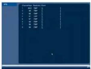
Discharge Request Data 1 S17 T20P 2 S18 T20P 3 S19 T20P 4 S20 T20P 5 S21 T20P 6 S22 T20P 7 S23 T20P 8 S24 T20P 9 S25 T20PTo access BPS:
- From the Main Menu, click and then select BPS.
14.2.9 Log
The Log sub-menu allows you to search for system logs.

text_image
File Date: 19.04.2016 12:00:00 AM File Size: 34.25 25 10 00:00 PM Search Add to Add to Add to Add to Add to Add to Add to Add to Add to Add to Add to Add to Add to Add to Add to Add to Add to Add to Add to Add to Add to Add to Add to Add to Add to Add to Add to Add to Add to Add to Add to Add to Add to Add toUsing the Main Menu14
text_image
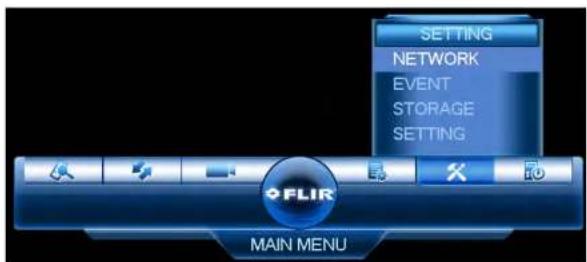
SETTING NETWORK EVENT STORAGE SETTING FLIR MAIN MENU14.3.1 Network
The Network menu allows you to configure network parameters for your system.
14.3.2 Selecting DHCP or Static IP Address (TCP/IP)
The TCP/IP menu allows you to configure IP address settings.
To configure IP address settings:
-
From the Main Menu, click ✕ and then select Network>TCP/IP.
-
Check DHCP (recommended) to let the system automatically obtain an IP address from the router or uncheck to assign a static IP address.

If you are using DDNS connectivity, port forwarding is required for the HTTP Port (default: 80) and TCP (Client Port) (default: 35000).
To configure system ports:
- From the Main Menu, click X and then select Network>Connection.

text_image
TCP/IP CONNECTION INF COM HTTP FSLR DML FTP FTP Pin TCP Pin TCP Pin TCP Pin TCP Pin TCP Pin TCP Pin TCP Pin TCP Pin TCP Pin TCP Pin TCP Pin TCP Pin TCP Pin TCP Pin TCP Pin TCP Pin TCP Pin TCP Pin TCP Pin TCP Pin TCP Pin TCP Pin TCP Pin TCP Pin TCP Pin TCP Pin TCP Pin TCP Pin TCP Pin TCP Pin TCP Pin TCP Pin TCP Pin TCP In- Configure the ports as needed and click OK to save changes.

NOTE
Up to 3 devices may connect to the system at the same time when using FLIR Cloud™.
14.3.4 Configuring DDNS Settings
FLIR DDNS is available as an optional connectivity option. Please see 18 DDNS Setup (Advanced), page 146 for details.
The primary connectivity option uses FLIR Cloud™ to connect to your system over the Internet without requiring port forwarding or DDNS registration. For details, see 15 Connecting to Your System Over the Internet on PC or Mac, page 74.
To configure DDNS Settings:
- Under User ID, enter your DDNS User Name.
- Under Password, enter your DDNS Device password.
- Click OK to save your settings.

NOTE
Please allow 10–15 minutes for the DDNS servers to update with your new DDNS address before attempting to connect.
14.3.5 Configuring Email Alerts
You can configure the system to send out email alerts for motion detection or other events.

NOTE
To send out motion detection alerts, you must enable the Send Email option for motion detection on each camera you would to receive alerts from. For details, see 14.3.7 Configuring Motion Detection, page 55.

NOTE
SMTP server connection information is required to set up email alerts. Contact your email service provider to retrieve your SMTP server information.
To configure Email Alerts:
- From the Main Menu, click X and then select Network>Email.
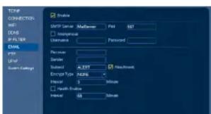
text_image
TCP CONNECTION: INT: DOB FILTER EMAIL Type Size System Settings Enable SMTP Server: Microsoft Print 857 Generic Username: Password Receiver Standard: XERT Sudan: XERT Encryption Type: ADB6 Initial: 3 Minute Final: Update Initial: 50 Subnet Houchwork-
Configure the following:
-
SMTP Server: Enter the SMTP server address.
- Port: Enter the port used by the SMTP server.
- Anonymous: Check if your server supports anonymous log ins. Otherwise, leave this unchecked.
- User Name: Enter the SMTP user name.
- Password: Enter the SMTP password.
- Receiver: Enter the email address that will receive alerts.
- Sender: Enter the sender's email address.
- Subject: Enter the subject line for the email alert.
- Attachment: Check to include a jpg image attachment of the camera.

You must enable the Snapshot option for motion detection on each camera you would to receive attachments. For details, see 14.3.7 Configuring Motion Detection, page 55.
- Encrypt Type: Select SSL or TLS if your server uses encryption. Select None if your server does not use encryption.
- Event Interval: Enter the interval between alert emails.
- Health Enable: Check to enable health check emails. Health check emails will be sent periodically to ensure that the system is functioning normally.
-
Interval: Enter the interval in minutes for health check emails.
-
Click Test to send a test email.
-
Click OK to save settings.
14.3.6 Event
The Event menu allows you to configure settings for motion detection, video loss, and system warnings.
14.3.7 Configuring Motion Detection
Motion Detection events allow the system to mark footage that has motion. This allows you to quickly locate relevant footage through Search. You can also configure system re-
Using the Main Menu14
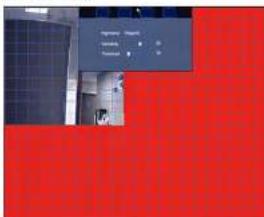
- Click Setup next to Region to configure which areas of the image will be enabled for motion detection. A grid will appear over the camera's live view.
Motion Grid
text_image
Import Export Delete Delete- Areas enabled for motion detection are shown in color and areas that are disabled are transparent.
- Hover the mouse at the top of the screen to select which motion area you would like to configure. You can set up to 4 motion detection areas and customize the sensitivity and threshold for motion detection separately for each area between 0 (lowest) and 100 (highest).
- The Sensitivity determines how sensitive the camera is to motion. For example, if the sensitivity is high, small amounts of motion are more likely to trigger an event. It is recommended to select a Sensitivity between 30\~70.
- The Threshold determines how much motion is required to trigger an event. If the amount of motion exceeds the threshold, an event occurs. It is recommended to select a Threshold between 10–50.
• Right-click when finished.

NOTE
It is recommended to have a second person walk in front of the camera to test different Sensitivity and Threshold settings to determine the best setting for your camera's location.
-
Configure the following system actions when motion is detected:
-
Alarm Out: Check the box to activate alarm output devices (not included) that will trigger when the selected channel detects motion. Select the alarm output devices that will be activated when motion is detected.
- Latch: Enter the number of seconds an alarm output device will activate after motion is detected.
• Show Message: Check to enable an on-screen pop-up when one of your cameras detects motion. On-screen pop-up shows the channels an event occurred on and the type of event. - Alarm Upload: Check to enable the system to upload alerts to FLIR Cloud™ Client.
- Send Email: Check to enable email alerts. You must configure email alerts before you will be able to receive them (see 14.3.5 Configuring Email Alerts, page 54).
- Recording Channel: Select the channels that will record when motion is detected on the selected channel.
- PTZ Activation: Check to enable PTZ actions when motion is detected (PTZ camera required; not included). Click Setup to select which PTZ actions will be taken by each camera.
- Buzzer: Check to enable the system buzzer.
- Sequence: Check to enable a custom sequence mode when motion is detected on the selected channel. Then click the channels you would like to display in the custom sequence mode.
-
Snapshot: Check to save a snapshot when the camera detects motion.
-
Click OK to save changes.
14.3.8 Configuring Video Loss Settings
Video Loss occurs if the system loses connection to one of the cameras.
To configure Video Loss settings:
- From the Main Menu, click X and then click Event>Motion>Video Loss.

-
Configure the following to customize settings for video loss events:
-
Period: Click Setup to configure a schedule for video loss events. It is recommended to leave this on the default setting, so you can be alerted at any time one of your cameras loses video.
- Alarm Out: Select the alarm output devices (not included) that will trigger when video loss occurs.
- Latch: Enter the number of seconds an alarm output device will activate after video loss occurs.
- Show Message: Check to show a popup message on the monitor if one of your cameras loses video.
- Alarm Upload: Check to enable the system to upload alerts to FLIR Cloud™ Client.
- Send Email: Check to enable email alerts. You must configure email alerts before you will be able to receive them (see 14.3.5 Configuring Email Alerts, page 54).
- Record Channel: Click the checkbox to enable video recording when video loss occurs. You can then select the channels the system will record when video loss occurs on the currently selected channel.
- PTZ Activation: Check to enable PTZ actions when video loss occurs (PTZ camera required; not included). Click Setup to select which PTZ actions will be taken by each camera.
- Post_REC: Enter the number of seconds the system will record after video loss occurs.
- Snapshot: Click the box to enable snapshot recording when video loss occurs. You can then select which channels will save snapshots when video loss occurs on the currently selected channel.
- Sequence: Check to enable a custom sequence mode when video loss occurs on the selected channel. Then click the channels you would like to display in the custom sequence mode.
-
Buzzer: Check to enable the system buzzer when video loss occurs on the currently selected channel.
-
Click OK to save changes.
14.3.9 Configuring Tamper Detection
You can choose how the custom react to any clone of tamnaring /i a camorae hain
Using the Main Menu14
3. Check Enable.
- Select a Sensitivity level to determine the amount of movement needed to trigger tamper detection.
| NOTE |
| Tampering events usually involve dramatic changes in the camera image, so it is recommende keep the sensitivity for tamper detection relatively low. |
- Click Setup next to Period to customize active hours for tamper detection (for example, during hours when your business is closed).
- By default, tamper detection is enabled at all times. Click or click-and-drag over portions of the schedule you want to add/remove from the schedule.

text_image
Temp Temp Temp Temp Temp Temp Temp Temp Temp Temp Temp Temp Temp Temp Temp Temp Temp Temp Temp Temp Temp Temp Temp Temp Temp Temp Temp Temp Temp Temp Temp Temp Temp Temp Temp Temp Temp Temp Temp Temp Temp Temp Temp Temp Temp Temp Temp Temp Temp Temp Temp- Click beside any days you want to link while adding/removing sections of the schedule, or beside All to link all days.
- Click Setup to manually enter different time periods for the active hours on the selected day.

Using the Main Menu14
- Check recording and system options in the event of tampering: Record Channel, PTZ Activation, Sequence and Snapshot.
- For options with channel numbers beside them, select the channels that should be included. For example, check Sequence, then select the channels your system should sequence through.

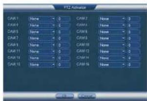
- Click Setup next to PTZ Activation to determine how PTZ cameras behave during a tampering event. Choose an event from the PTZ channel's dropdown to select Preset, Tour or Pattern. Enter the ID number for the desired preset viewing point, tour or pattern to have it executed in the event of tampering. Click OK to confirm.
text_image
CAM 1 None - 0 CAM 2 None - 0 CAM 3 None - 0 CAM 4 None - 0 CAM 5 None - 0 CAM 6 None - 0 CAM 7 None - 0 CAM 8 None - 0 CAM 9 None - 0 CAM 10 None - 0 CAM 11 None - 0 CAM12 None - 0 CAM 13 None - 0 CAM14 None - 0 CAM 15 None - 0 CAM16 None - 0 Control Control- Click OK to save changes.
14.3.10 Configuring Hard Drive Warnings
Hard drive warnings will notify you if an issue is detected with the hard drive.
To configure hard drive warnings:
-
From the Main Menu, click X and then click Event>Warning>HDD.
-
Under Event Type, select the hard drive event you would like to configure.
-
No Disk: No hard drive detected.
- Disk Error: A hard drive error has been detected.
- Disk Full: The hard drive is full or almost full. You can enter the percentage of disk space remaining that will trigger a warning under Less Than (e.g. when less than 10% of the hard drive is empty, trigger a warning). Disk Full warnings will not occur overwrite is enabled.
-
All: Configure warnings for all hard drive events.
-
Configure the responses the system will take when the selected event occurs:
-
Alarm Out: Activate selected alarm out devices. Use Latch to select the number of seconds the alarm out device will be activated.
• Show Message: Show a popup message on the monitor. - Alarm Upload: Check to enable the system to upload alerts to FLIR Cloud™ Client.
- Send Email: Check to enable email alerts. You must configure email alerts before
you will be able to receive them (see 14.3.5 Configuring Email Alerts, page 54). -
Buzzer: Check to activate the system buzzer.
-
Click OK to save changes.
14.3.11 Configuring Network Warnings
Network warnings will notify you if your system loses connection to the Internet or local network or if there is an issue on your network.
To configure network warnings:
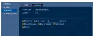
- From the Main Menu, click and then click Event>Warning>Network.
-
Configure the following for the selected event type:
-
Alarm Out: Activate selected alarm out devices. Use Latch to select the number of seconds the alarm out device will be activated.
- Enable: Check to enable the selected event type.
- Show Message: Check to show a popup message when the selected event occurs.
- Send Email: Check to enable email alerts. You must configure email alerts before
you will be able to receive them (see 14.3.5 Configuring Email Alerts, page 54). -
Buzzer: Check to activate the system buzzer.
-
Click OK to save changes.
14.3.12 Storage
The Storage menu allows you to configure the recording schedule and hard drives connected to the system.
14.3.13 Configuring the Video Recording Schedule
You can set a custom recording schedule according to your needs. For example, you can set the system to record continuously during business hours and record on motion detection only outside of business hours.
A custom recording schedule helps reduce the amount of hard drive space required, increasing the time your system can retain recordings.
To configure the video recording schedule:
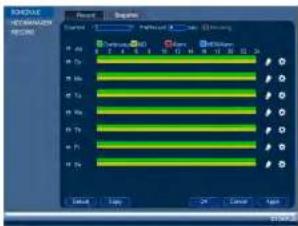
- From the Main Menu, click X and then click Storage>Schedule>Record.
- Under Channel, select the channel you would like to configure or select All.
Using the Main Menu14
- Configure the schedule as needed:
text_image
CONTROL COMPARATION REDAVING Control Panel Control Panel 1 Control Panel 2 Control Panel 3 Control Panel 4 Control Panel 5 Control Panel 6 Control Panel 7 Control Panel 8 Control Panel 9 Control Panel 10 Control Panel 11 Control Panel 12 Control Panel 13 Control Panel 14 Control Panel 15 Control Panel 16 Control Panel 17 Control Panel 18 Control Panel 19 Control Panel 20 Control Panel 21 Control Panel 22 Control Panel 23 Control Panel 24 Control Panel 25 Control Panel 26 Control Panel 27 Control Panel 28 Control Panel 29 Control Panel 30 Control Panel 31 Control Panel 32 Control Panel 33 Control Panel 34 Control Panel 35 Control Panel 36 Control Panel 37 Control Panel 38 Control Panel 39 Control Panel 40 Control Panel 41 Control Panel 42 Control Panel 43 Control Panel 44 Control Panel 45 Control Panel 46 Control Panel 47 Control Panel 48 Control Panel 49 Control Panel 50 Control Panel 51 Control Panel 52 Control Panel 53 Control Panel 54 Control Panel 55 Control Panel 56 Control Panel 57 Control Panel 58 Control Panel 59 Control Panel 60 Control Panel 61 Control Panel 62 Control Panel 63 Control Panel 64 Control Panel 65 Control Panel 66 Control Panel 67 Control Panel 68 Control Panel 69 Control Panel 70 Control Panel 71 Control Panel 72 Control Panel 73 Control Panel 74 Control Panel 75 Control Panel 76 Control Panel 77 Control Panel 78 Control Panel 79 Control Panel 80 Control Panel 81 Control Panel 82 Control Panel 83 Control Panel 84 Control Panel 85 Control Panel 86 Control Panel 87 Control Panel 88 Control Panel 89 Control Panel 90 Control Panel 91 Control Panel 92 Control Panel 93 Control Panel 94 Control Panel 95 Control Panel 96 Control Panel 97 Control Panel 98 Control Panel 99 Control Panel 100- Check Continuous, MD (motion detection), Alarm, or Alarm & MD to select the recording type you would like to configure.
- Click and drag on each day to customize the recording schedule. The schedule is set up as a grid, which each block representing one hour.
- Click next to All to link the recording schedules for all days. The icon for a day changes to when days are linked. You can also click the boxes next to individual days to link them to each other. If the recording schedule is linked, changes made to one of the days will apply to every day that is linked.
- Click to disable all recording of the selected type on the selected day.
-
Click 🎨 If you need to set a more precise schedule down to the minute.
-
Click OK to save changes.
14.3.14 Configuring Pre-Recording
The system can pre-record video when motion detection events occur.
Using the Main Menu14
14.3.15 Configuring the Snapshot Schedule
You can set a schedule for recording snapshots from the cameras.
To set up the snapshot schedule:
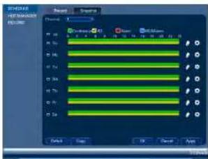
- From the Main Menu, click and then click Storage>Schedule>Snapshot.
text_image
SINEMA HUMANIA REDA Balance Balance Balance Balance Balance Balance Balance Balance Balance Balance Balance Balance Balance Balance Balance Balance Balance Balance Balance Balance Balance Balance Balance Balance Balance Balance Balance Balance Balance Balance Balance Balance Balance Balance Balance Balance Balance Balance Balance Balance Balance Balance Balance Balance Balance Balance Balance Balance Balance Balance Finish-
Under Channel, select the channel you would like to configure or select All.
-
Configure the schedule as needed:
-
Check Continuous, MD (motion detection), Alarm, or Alarm & MD to select the recording type you would like to configure.
- Click and drag on each day to customize the recording schedule. The schedule is set up as a grid, which each block representing one hour.
- Click next to All to link the recording schedules for all days. The icon for a day changes to when it is linked. You can also click the boxes next to individual days to link them to each other. If the recording schedule is linked, changes made to one of the days will apply to every day that is linked.
Using the Main Menu14
To configure holidays:
- From the Main Menu, click X and then click Setting>General>Holiday.
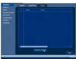
text_image
SINEMA DUAL MOSI P301A120CM KOSIUP Cable Release RPSXT IP3008 General Desktop Tools Help Add New Settings Type-
Click Add New Holidays.
-
Configure the following:
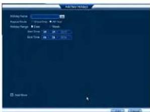
text_image
Add New Add Mode Add New Position: Default Mode: 0.0000 Add Mode: Reset Time: 24.0000 End Time: 24.0000 Add New Add New• Holiday Name: Enter a name for this holiday
Using the Main Menu14
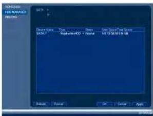
- From the Main Menu, click X and then click Storage>HDD Manager.
text_image
SOMIAL HOS MANAGER REDAVING Catal: SATA SATA 1 Type: Normal Satal with HOC - Normal End Store Price Range SUT 03/08/2014 GB Return Finish OK Cancel Apply-
Select the hard dive you would like to format and then click Format. Click OK to confirm
-
Click OK to save changes. The system will restart to complete the formatting process.
14.3.18 Configuring Hard Drive Type
The system supports the following hard drive types:
- Read-write HDD: Normal recording hard drive.
- Read-only HDD: The system can playback data from this hard drive, but it will not record to it.
- Mirroring HDD: The hard drive will be used for mirror recording only. You must set up mirroring recording before this feature will work.
To set the hard drive type:
- From the Main Menu, click X and then click Storage>HDD Manager.

Using the Main Menu14
To configure general settings:
- From the Main Menu, click X and then click Setting>General>General.

text_image
SUPPORT TYPE HKEY POTATO MOUNTED account Category Name SUPPORT MODEL Symbol Symbol Type Form1 Symbol1 Symbol2 Symbol3 Symbol4 Symbol5 Symbol6 Symbol7 Symbol8 Symbol9 Symbol10 Symbol11 Symbol12 Symbol13 Symbol14 Symbol15 Symbol16 Symbol17 Symbol18 Symbol19 Symbol20 Symbol21 Symbol22 Symbol23 Symbol24 Symbol25 Symbol26 Symbol27 Symbol28 Symbol29 Symbol30 Symbol31 Symbol32 Symbol33 Symbol34 Symbol35 Symbol36 Symbol37 Symbol38 Symbol39 Symbol40 Symbol41 Symbol42 Symbol43 Symbol44 Symbol45 Symbol46 Symbol47 Symbol48 Symbol49 Symbol50 Symbol51 Symbol52 Symbol53 Symbol54 Symbol55 Symbol56 Symbol57 Symbol58 Symbol59 Symbol60 Symbol61 Symbol62 Symbol63 Symbol64 Symbol65 Symbol66 Symbol67 Symbol68 Symbol69 Symbol70 Symbol71 Symbol72 Symbol73 Symbol74 Symbol75 Symbol76 Symbol77 Symbol78 Symbol79 Symbol80 Symbol81 Symbol82 Symbol83 Symbol84 Symbol85 Symbol86 Symbol87 Symbol88 Symbol89 Symbol90 Symbol91 Symbol92 Symbol93 Symbol94 Symbol95 Symbol96 Symbol97 Symbol98 Symbol99 Symbol100- Configure the following:
• Device Type: Shows the model number of your system.
- Device No.: Select the remote control address of the system. See 7.1 Setting the Remote Control Address, page 14.
- Language: Set the system languages. Available options are English, French, and Spanish.
• Video Standard: Select NTSC (North America) or PAL (Europe).
- HDD Full: Select Overwrite for the system to overwrite the oldest recordings when the hard drive is full or select Stop Record for the system to stop recording when the hard drive is full.
- Pack Duration: Select the length (in minutes) of video files stored on the system. For example, if this is set to 30 minutes, the system will create a new video file for each 30 minutes of continuous recording.
- Instant Playback: Select the amount of time (in minutes) the system will go back when instant playback is activated in live view.
- Auto Logout: Select the idle time (in minutes) before the system will logout the cur-
Using the Main Menu14
To set the monitor resolution:
- From the Main Menu, click ✕ and then click Setting>Display>Display.

text_image
LIGHT DISPLAY MUST AVOC Lightbox ACQUANT Temp/Bitting INT/RESET UP/PAGE Display Sequence RGB Transparency Time Display Resolution 100x100 Channel Display Image Balance OK Cancel Apply-
Under Resolution, select the correct resolution for your monitor: 1920x1080, 1280x1024, 1280x720, or 1024x768.
-
Click OK to save changes. Click OK again to restart the system using the new resolution.
To configure other display settings:
- From the Main Menu, click X and then click Setting>Display>Display.

text_image
MEDIA Media MUST RASS DATA/COM ACCOUNT Data Backup DISPLAY PULSE Display Sequence 02 Transparency Time Stable Resolution: 1000x75 Channel Display Image ExchangeUsing the Main Menu14

text_image
NOTE When configuring your PTZ keyboard, the RS232 address of your system is set under Device No. in the Main Menu: General-General GENERAL DISPLAY ADDRESS POTATO/BOARD ACCOUNT Setup Backer DEFAULT OPFACES General Smart Time Default Type Device No. Language DOLGL Word Standard NPSC HSD Full Univariate Part Duration 0% Select Picture 1% Auto Logual 0% Navigation Bar Setup Board Monitor Speed New... General General Default Time Default Type Device No. Language DOLGL Word Standard NPSC HSD Full Univariate Part Duration 0% Select Picture 1% Auto Logual 0% Navigation Bar Setup Board Monitor Speed New...To configure RS232 settings for a PTZ keyboard:
-
From the Main Menu, click and then click Setting>RS232.
-
Configure the following:

• Function: Select Netkeyboard.
- Baud Rate: Select a baud rate that is compatible with your PTZ keyboard.
- Data Bits: Select a data bits setting that is compatible with your PTZ keyboard.
- Stop Bits: Select a stop bit setting that is compatible with your PTZ keyboard.
-
Parity: Select a parity setting that is compatible with your PTZ keyboard.
-
Click OK to save changes.
14.3.22 Saving Your System Configuration to a USB Thumb Drive
Using the Main Menu14
- From the Main Menu, click X and then click Setting>Config Backup.
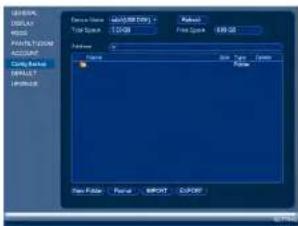
text_image
SHELL DISPLAY TITLE POTATO CODE ACCOUNT COM/RESET INSTALL ORDER Form Name: Q200100007 Form Name: Q200100007 Format: Normal Format: Normal Format: Normal Format: Normal Format: Normal Format: Normal Format: Normal Format: Normal Format: Normal Format: Normal Format: Normal Format: Normal Format: Normal Format: Normal Format: Normal Format: Normal Format: Normal Format: Normal Format: Normal Format: Normal Format: Normal Format: Normal Format: Normal Format: Normal Format: Normal Format: Neutral- Under Device Name, select the USB device where you would like to save the configuration.
- Click EXPORT to save your current system configuration.
To restore a saved system configuration:
- Insert a USB thumb drive (not included) with a saved system configuration into one of the USB ports.
- From the Main Menu, click X and then click Setting>Config Backup
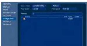
text_image
SYSTEM DISPLAY WRITE PACTOR ORDER ACCOUNT CONFIGER DEFAULT ERROR Device Name: 10000000000000000000000000000000000000000000000000000000000000000000000000000000000000000000000000000 Data Type: Normal Size: 5.25 px Size: 5.25 px Color: 16.75% Color: 16.75% Color: 16.75%Using the Main Menu14
To reset the system to factory default settings:
- From the Main Menu, click X and then click Setting>Default.
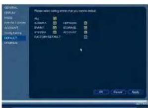
text_image
GENERAL DISPLAY HKEY FATORY ORDER ACCOUNT Supply Banking DEFAULT CREATE Please action setting active that you create default. Auto: DATA: BASE: DATA: STANDARD SYSTEM: ACCOUNT FACTORY DEFAULT: OK Cancel Apply-
Check the menus you would like to reset to default settings or check Factory Default to reset the entire system to default settings.
-
Click OK.
14.3.24 Upgrading Firmware from USB
Firmware upgrades provide enhanced functionality. The system will automatically check for firmware upgrades if it is connected to the Internet. The system also supports firmware upgrades from a USB thumb drive (not included).
To upgrade firmware from a USB drive:
-
Download the firmware upgrade from www.flir.com/security/pro.
-
Extract the firmware file and copy the firmware to a blank USB thumb drive.
| NOTE |
| Do not have any folders on the USB thumb drive—just the firmware file. |
Using the Main Menu14
- Select the firmware file on the USB drive and click Start.
| WARNING |
| DO NOT POWER OFF THE SYSTEM OR DISCONNECT THE POWER CABLE DURING FIRM-WARE INSTALLATION |
Using the Main Menu14
14.4 Shutdown
Use the Shutdown menu to shutdown, restart, or log out of the system.
To access the Shutdown menu:
-
From live view, right-click and select Main Menu.
-
Enter the system User Name (default: admin) and Password (default: 000000) and click OK.

- Select one of the following:
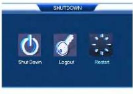
text_image
SHUTDOWN Shut Down Logout Restart- Logout: Log out the account that is currently active.
- Shutdown.
- Restart.
Connecting to Your System Over the Internet on PC or Mac
This system features connectivity using the exclusive FLIR Cloud™. This cloud-enabled service allows for Internet connectivity without requiring any network configuration. Up to 3 devices may connect to the system at the same time.

text_image
NOTE • Except where noted, the PC and Mac instructions in this section are the same. • For smartphone/tablet setup, see 17 Connecting to your System Using Smartphone or Tablet Apps, page 105. • For the latest list of supported apps and devices, visit www.llr.com/security/pro.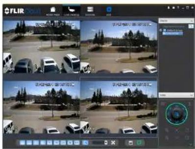
text_image
FLIR FLIR FLIR FLIR FLIR FLIR FLIR FLIR FLIR FLIR FLIR FLIR FLIR FLIR FLIR FLIR FLIR FLIR FLIR FLIR FLIR FLIR FLIR FLIR FLIR FLIR FLIR FLIR FLIR FLIR FLIR FLIR FLIR FLIR F1000000000000000000000000000000000000000000000000000000000000000000000000000000000000000000000000000015.1 System Requirements
Your system must meet the system requirements below:
| Description Requirement | |
| CPU Core 2 Duo 3.0GHz |
- Reconnect the power adapter to power the system back on.
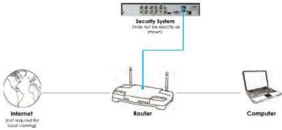
flowchart
graph LR
    A["Internet\n(not required for local viewing)"] --> B["Router"]
    C["Computer"] --> B
    B --> D["Security System\n(may not be exactly as shown)"]
15.3 Step 2 of 3: Obtain the system's Device ID
The Device ID is a unique code that allows your system to handshake with FLIR Cloud™ servers for a secure connection over the Internet.
To find the Device ID:
- The Device ID is located on a sticker on the system.

text_image
Device ID: xxxxxxxxxxxx- Write down the Device ID of the system.
15.1 Sten 3 of 2: Connect to the System Over the Internet
- Log into the Client Software using the Client Software user name (default: admin) and password (default: admin) and then click Login.

text_image
FLIR Cloud User Name: admin Password: ****** Register for Password { Login } { Exit }- Click Add Device.
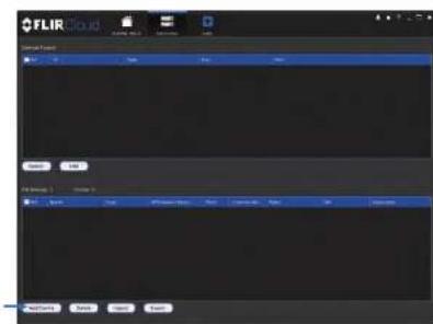
text_image
FLIR Cloud Current Portion Name: FLIR Status: Normal File Name: Normal Access: Normal Add: Cancel Add: Cancel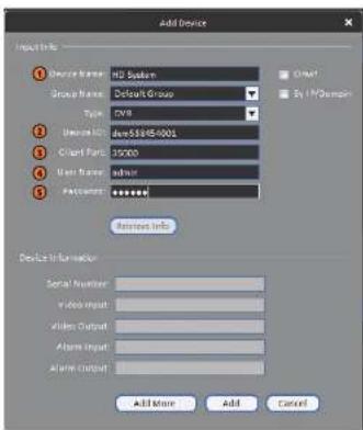
text_image
Add Device Adjust Info 1 Device Name: H2 System Group Name: Default Group Type: GWR 2 Devices ID: dev58495-0001 3 Guard Part: 15000 4 User Name: admin 5 Password: ****** Returns Info Device Information Serial Number: Video Input: Alters Output: Alters Input: Alters Output: Add More Add Cancel5.1. Device Name: Choose a name for your system of your choice.
5.2. Device ID: Manually enter the Device ID printed on the label.
5.3. Client Port: Enter the Client Port (default: 35000).
5.4. User Name: Enter the system User Name (default: admin).
5.5. Password: Enter the system Password (default: 000000)
- Click Add. If this is the first time you are connecting, you will be prompted to change the system password.
- Click and drag Default Group to the display window to open your cameras in live view.
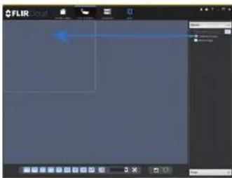
text_image
FLIR Color FLIR ColorCongratulations! You can now connect over the Internet to view and playback video on your computer.
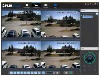
text_image
Screenshot of a video editing interface showing a grid of surveillance feeds with vehicle images and a circular control panel.Using FLIR Cloud™ Client for PC or Mac
FLIR Cloud™ Client allows you to connect to multiple systems from a PC or Mac.
16.1 Home Page
The Home Page allows you to access all the tabs within the software. Each tab allows you to access different features.

Click a tab from the Home Page to open it or click a button at the top of the screen from within any tab to open a new tab.
16.2 Live View
The Live View tab is where you can view live video from connected systems.
To view live video from a system:
-
Click 📄 and then click 📋 to create a Live View tab.
-
Click and drag a DVR, NVR, group, or individual camera to open live video. To access individual camera, you can click + to expand groups or customs
16.2.1 Live View Controls
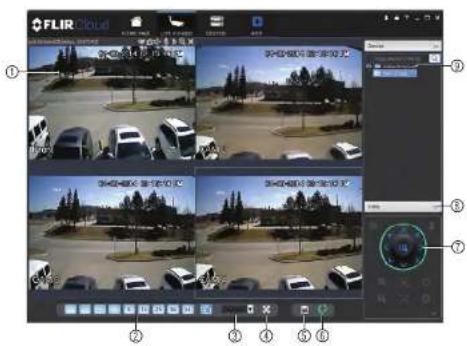
text_image
FLIR Cloud ① ② ③ ④ ⑤ ⑥- Live display: Double-click to expand the area. Right-click to access additional options. Hold the mouse over the display area to access the camera toolbar.
Camera toolbar:

text_image
Sub Stream(205kbps, 352*240) ① ②③④⑤⑥⑦⑧1.1. Streaming quality: Shows the bitrate and resolution for the stream, and shows
If display is showing the Sub Stream or Main Stream.
1.2. Manual recording: Click to start/stop manual recording.
1.2 Snapshot Click to save a snapshot
- Full-screen: Click to open full-screen mode. Press ESC to exit full-screen mode.
- Save view: Click to save the current display layout and open cameras as a view. Then enter a name for the view.
- Start/stop tour: Click to start the tour. During the tour the client will cycle through all saved views every few seconds. Click again to stop the tour.
- PTZ Controls: Controls for PTZ cameras (not included). See 16.3 Controlling PTZ Cameras, page 82 for details.
- View: Click View to access view menu. Then double-click on a view to open it in the display area.
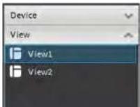
- Devices: Shows a list of groups, cameras, and systems connected to the client. Drag items to the display area to open live video. Right-click to view additional options.
16.2.2 Opening Live View in Multiple Monitors
If your computer has multiple monitors, you can open more than one Live View tab and move them to secondary monitors. This allows you to monitor cameras on multiple monitors at the same time.

text_image
NOTE Using multiple monitors significantly increases the amount of computing resources necessary to run application and may affect performance.- Click and drag the tab outside of the client window to create a new window. You can drag the window to one of the secondary monitors.
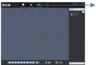
text_image
FLIR FLIR FLIR
text_image
Result FLIR FLIR FLIR FLIR FLIR FLIR FLIR FLIR FLIR FLIR FLIR FLIR FLIR FLIR FLIR FLIR FLIR FLIR FLIR FLIR FLIR FLIR FLIR FLIR FLIR FLIR FLIR FLIR FLIR FLIR FLIR FLIR FLIR FLIR16.3 Controlling PTZ Cameras
If you have PTZ cameras (not included), you can control them using the client.

NOTE
PTZ controls:
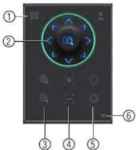
text_image
Diagram of a remote control panel with labeled buttons and navigation icons-
Open menu: Click to open camera OSD menu controls. This feature may not be supported for all camera models.
-
Move camera: Click the arrows to move the camera. Click to open dynamic zoom mode. Then click and drag in the video area to zoom in the camera on an area.
-
Zoom +/-: Click to zoom the camera in and out.
-
Focus +/-: Click to increase/decrease the focus.
-
Ins +/- Click to increase/decrease the Ins.
- Advanced: Click to access advanced PTZ controls
16.3.1 PTZ Presets
Presets will save a camera position for quick retrieval.
To add presets:
- Select the number of the preset you would like to add.

text_image
1 8 Preset 1 Input name- Move the camera to the desired position.
- Click to save the current position as a preset.
To go to a saved preset:
- Select the preset number from the list or click to go to the currently selected preset.
16.3.2 PTZ Tours
Tours will cycle through a set of presets.
To configure a PTZ tour:
- Click ▼ to open the Advanced controls. Select Tour.
- Click

- Use the chart to select which presets you would like to include in the tour and the order of presets.
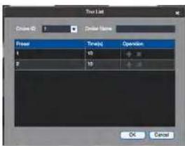
text_image
Tool List Clear Mode 0 Clear Mode Clear Time(s) Operation L 10 20 P 15 OK Cancel- Preset: Select the preset number.
- Time(s): Enter the time in seconds the camera will remain on the selected preset.
-
Operation: Click + to add a preset to the tour. Click to delete a preset from the tour.
-
Click OK to save changes.
To run a PTZ tour:
- Select the tour number and click

16.3.3 PTZ Pattern
Patterns automatically cycle the camera between two positions.
To create a pattern:
- Click ▼ to open the Advanced controls. Select Pattern.
- Select the number of the pattern you would like to set up.
16.3.4 PTZ Scan
Scan automatically cycles between a left and right point.
To set up scan mode:
- Click ▼ to open the Advanced controls. Select Scan.
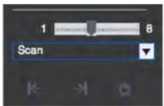
- Move the camera to the desired left position and click.
- Move the camera to the desired right position and click.
To run scan mode:
- Click
16.3.5 PTZ Pan
Pan makes the camera continuously pan 360°.
To run Pan mode:
- Click ▼ to open the Advanced controls. Select Pan.
- Click 🔒.
16.4 Playback
To playback video:
- Check the channels you would like to play back from in the Device List.
- Under Type, check the file types you would like to search for.
• All: All recordings.
• General: Continuous recordings.
• MD: Motion recordings.
- Alarm: Alarm recordings. Your system must support alarm devices (not included) to use this feature.
- Under Stream, select Main Stream to search for Main Stream recordings (high qual-
ity) or Sub Stream to search for Sub Stream recordings (smaller file size). - Select the start time and end time for your search under From and To. You may not
search more than 24 hours of video. - Click Search. Wait for the client to find video saved to the system.
- Click inside the play back bar to start playback.
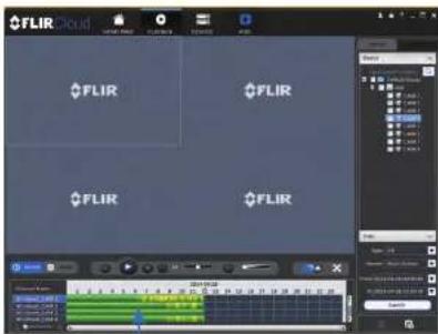
text_image
FLIR FLIR FLIR FLIR FLIR16.5 Playback Controls
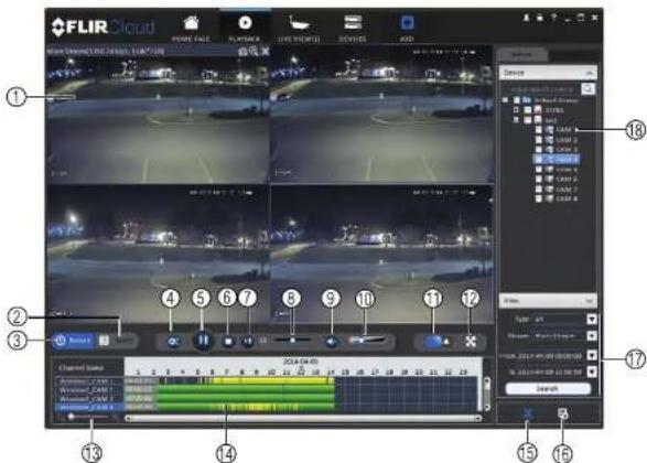
text_image
FLIR Cloud Main Sequence: FLIR Cloud Number: 1 Position: 0 Balance: 0.0000 Balance: 0.0000 Balance: 0.0000 Balance: 0.0000 Balance: 0.0000 Balance: 0.0000 Balance: 0.0000 Balance: 0.0000 Balance: 0.0000 Balance: 0.0000 Balance: 0.0015 Balance: 0.0015 Balance: 0.0015 Balance: 0.0015 Balance: 0.0015 Balance: 0.0015 Balance: 0.0015 Balance: 0.0015 Balance: 0.0015 Balance: 0.0015 Balance: 0.0016 Balance: 0.0016 Balance: 0.0016 Balance: 0.0016 Balance: 0.0016 Balance: 0.0016 Balance: 0.0016 Balance: 0.0016 Balance: 0.0016 Balance: 0.0017 Balance: 0.0017 Balance: 0.0017 Balance: 0.0017 Balance: 0.0017 Balance: 0.0017 Balance: 0.0017 Balance: 0.0018 Balance: 0.0018 Balance: 0.0018 Balance: 0.0018 Balance: 0.0018 Balance: 0.0018 Balance: 0.0019 Balance: 0.0019 Balance: 0.0019 Balance: 0.0019 Balance: 0.0024 Balance: 0.0024 Balance: 0.0024 Balance: 0.0024 Balance: 0.0024 Balance: 0.0344 Balance: 2344 Balance: 2344 Balance: 2344 Balance: 2344 Balance: 2344 Balance: 2344 Balance: 2344 Balance: 2344 Balance: 2344 Balance: 2344 Balance: 2344 Balance: 2344 Balance: 2344- Display area: Double-click to expand/return to split-screen mode. Hold the mouse over the display area to open the camera toolbar.

-
Snapshot: Click to save a snapshot.
• Digital zoom: Click to enable digital zoom mode. Then click and drag to zoom -
Download list: Click to see a list of files you have downloaded and the progress of files that are currently downloading.
- Search: Search for video on the selected channels based on the search parameters you set.
- Device list: Select the channels you would like to search or playback video from.
16.6 Downloading Video to your Computer Hard Drive
You can download video to your computer hard drive to save important events or share them. It is recommended to download video of important events as soon as possible to ensure they are not overwritten by new recordings.

NOTE
PC Users: You may need to run FLIR Cloud™ Client as an administrator to download files to your hard drive.
To download video files:
- Start playing back video using the steps in 16.4 Playback, page 86.
- Click 📋 to start a video clip at the current playback time. Click to stop the video clip.
- Configure the following save options:
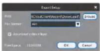
- Path: Use the default save folder or click Browse to select a different folder.
- File Format: Select Original Format to save to .dav format (requires the video player). Select AVI to save files to .avi format (can be played in VLC Media Player).

NOTE
To retrieve downloaded video files:
- PC Users: Browse to the folders listed in General>File.
- Mac Users: Browse to the folders listed in General>File. To get to the default location, open Applications in Finder, right click on FLIR Cloud Client and select Show Package Contents. Then, navigate to the desired folder.
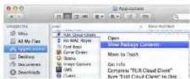
16.7 Alarm
The Alarm menu allows you to view a list of alarms received by the client software.

NOTE
You must set up alarms in the Alarm CFG menu before they will appear in this list. See 16.12 Alarm CFG, page 95 for more details.
To access Alarms:
- Click

and then click

Alarm menu overview:

text_image
FLIR Cloud ① ② ③ ④-
Options: Check to enable the following:
-
Display Link Video: Open live video to monitor alarms on a continuous basis.
- Display Overlay Window: Show the overlay controls. They allow you to enable/disable sound alerts and quickly jump back to the Alarm menu from another tab.

- Pause Refresh: Stop refreshing the live video in the video popup.
16.8 Log
The Log menu allows you to view logs for the client software or to view logs for connected systems.
To access logs:

To view client logs:
- Click Client Log to view logs for the client software.

text_image
FLIR FLIR FLIR FLIR FLIR FLIR FLIR FLIR FLIR FLIR FLIR FLIR FLIR FLIR FLIR FLIR FLIR FLIR FLIR FLIR FLIR FLIR FLIR FLIR FLIR FLIR FLIR FLIR FLIR FLIR FLIR FLIR FLIR FLIR FILR FILR FILR FILR FILR FILR FILR FILR FILR FILR FILR FILR FILR FILR FILR FILR FILR FILR FILR FILR FILR FILR FILR FILR FILR FILRS FILRS FILRS FILRS FILRS FILRS FILRS FILRS FILRS FILRS FILRS FILRS FILRS FILRS FILRS FILRS FILRS FILRS FILRS FILRS FILRS FILRS FILRS FILRS FILRS FILS FILS FILS FILS FILS FILS FILS FILS FILS FILS FILS FIFLMS10000000000000000000000000000000000000000000000000000000000000000000000000000000000000000000000000000- Click Device Log to view logs from connected systems.

-
Configure the following:
-
Start Time/End Time: Select the start and end times to search for logs.
-
Log Type: Select the type of logs to search for.
• Device Name: Select the system you would like to view logs from. -
Click Search.
16.9 E-map
E-Map allows you to place cameras over a still image. For example, you can use the E-Map to create a virtual map of your cameras over a floor plan of your home or business.
To create an E-map:
- Click

and then click

- Click Add Map.

- Configure the following:
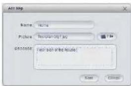
text_image
Add Step Name: None Picture: New!ing2013.02 Description: (see such of the image) Add Delete- Name: Enter a name for your e-map of your choice.
• Picture: Click File and then select a .png, .bmp, or .jpg image on your computer to
use as the e-map. -
Describe (optional): Enter a text description of the e-map.
-
Click Save.
-
Click Edit to edit the e-map.
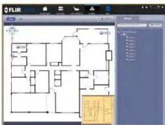
text_image
FLIR Floor 1 Floor 2 Floor 3 Floor 4 Floor 5 Floor 6 Floor 7 Floor 8 Floor 9 Floor 10 Floor 11 Floor 12 Floor 13 Floor 14 Floor 15 Floor 16 Floor 17 Floor 18 Floor 19 Floor 20 Floor 21 Floor 22 Floor 23 Floor 24 Floor 25 Floor 26 Floor 27 Floor 28 Floor 29 Floor 30 Floor 31 Floor 32 Floor 33 Floor 34 Floor 35 Floor 36 Floor 37 Floor 38 Floor 39 Floor 40 Floor 41 Floor 42 Floor 43 Floor 44 Floor 45 Floor 46 Floor 47 Floor 48 Floor 49 Floor 50 Floor 51 Floor 52 Floor 53 Floor 54 Floor 55 Floor 56 Floor 57 Floor 58 Floor 59 Floor 60 Floor 61 Floor 62 Floor 63 Floor 64 Floor 65 Floor 66 Floor 67 Floor 68 Floor 69 Floor 70 Floor 71 Floor 72 Floor 73 Floor 74 Floor 75 Floor 76 Floor 77 Floor 78 Floor 79 Floor 80 Floor 81 Floor 82 Floor 83 Floor 84 Floor 85 Floor 86 Floor 87 Floor 88 Floor 89 Floor 90 Floor 91 Floor 92 Floor 93 Floor 94 Floor 95 Floor 96 Floor 97 Floor 98 Floor 99- Double-click cameras on the map to open live video.
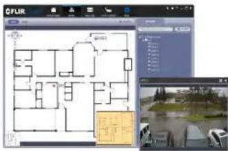
text_image
FLIR 100 200 300 400 500 600 700 800 900 100016.10 Devices
The Devices menu is where you can manage systems connected to the client software.
To access the Devices menu:
- Click and then click
Devices overview:

text_image
FLIR Studio ① ② ③ ④- Edit: Edit the connection details for the system.
16.11 Device Config
The Device Config menu allows you to remotely configure settings for connected systems.
To access the Device Config menu:

- Click on a system in the device list to see the settings available for that system and their configure settings as needed.
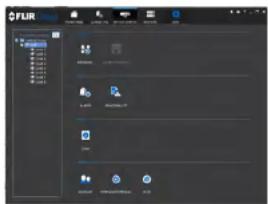
text_image
FLIR 文件(F) 编辑(E) 视图(V) 窗口(W) 帮助(H) 新建(N) 打开(O) 保存(S) 重命名(M) 粘贴(P) 复制(C) 粘贴(P) 剪切(T) 复制(C) 粘贴(P) 粘贴(P) 粘贴(P) 粘贴(P) 粘贴(P) 粘贴(P) 粘贴(P) 粘贴(P) 粘贴(P) 粘贴(P) 粘贴(P) 粘贴(P) 粘贴(P) 粘贴(P) 粘贴(P) 粘贴(P) 粘贴(P) 粘贴(P) 粘贴(P) 粘贴(P) 粘贴(P) 粘贴(P) 粘贴(P) 粘贴(P) 粘贴(P) 粘贴.P 粘贴(P) 粘贴(P) 粘贴(P) 粘贴(P) 粘贴(P) 粘贴(P) 粘贴(P) 粘贴(P) 粘贴(P) 粘贴(P) 粘贴(P) 粘贴(P) 粘贴(P) 粘贴(P) 粘贴(P) 粘贴(P) 粘贴(P) 粘贴(P) 粘贴(P) 粘贴(P) 粘贴(P) 粘贴(P) 粘贴(P) 粘贴(P) 粘贴(P)
NOTE
The settings available depend on the model of system you have.
16.12 Alarm CFG
The Alarm CFG menu allows you to configure alarms for the client software. The client software will alert you by popping up live video and playing sound alerts.

NOTE
- In the Alarm sources menu, you set up the parameters that trigger the alarm.

text_image
Screenshot of a software interface with a dialog box and toolbar, showing text fields and buttons in Chinese.- Under Alarm Type, select the alarm type that will trigger an alarm. For example, you can select Motion Detect for the alarm to be triggered by motion.
- Select the systems or channels you would like to trigger an alarm. Continuing the example, if CAM 1 is selected, the alarm will be triggered if there is motion on CAM 1.
-
Click Next.
-
In the Alarm link menu, you set up the responses to alarms. Select the channels that will pop up or alarm out devices (not included; not all systems support alarm out devices) that will be triggered by an alarm.
For each channel selected, configure the following:
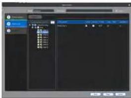
text_image
Screenshot of a software interface showing a dashboard with file list and playback controls, likely from an older media or video editing tool.• Video: Pop up a window with live video from the selected channel, like the one below.
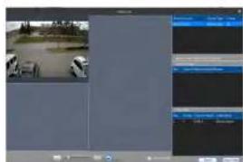
text_image
Screenshot of a video editing software interface showing a surveillance camera and timeline with Chinese text labels• Record: Record video from the selected channel.

To manage alarms:
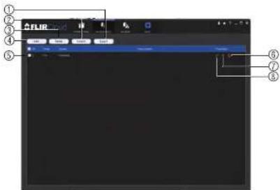
text_image
FLIR ① ② ③ ④ ⑤ ⑥ ⑦ ⑧- Export: Export current list of alarms as an xml file.
- Import: Import list of alarms.
- Delete: Delete selected alarm.
- Add: Add new alarm.
- Alarms.
- On/off: Click to enable/disable alarm.
- Delete: Click to delete alarm.
- Edit: Click to edit alarm settings.
16.13 Tour & Task
The Tour & Task menu is where you can set up custom views for the system. You can also set up tours, which sets the client to automatically cycle through views.
To start a tour:
- Click in Live View to start a tour. The live view will automatically cycle through all vinau you have got up in the Tour & Tack menu. Click again to stop the tour.
- Under Name, enter a name for your view.
- Under Stay Time, enter the number of seconds the view will be shown before the client switches to the next view.
- Select the split-screen mode you would like to use for the view and then click and drag channels to the empty grid areas to select channels to be shown in the view.
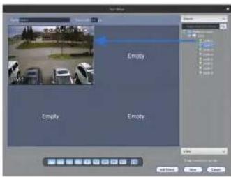
text_image
Empty Empty Empty- Click Save to save the view. Or click Add More to save the view and create another view.
16.14 Account
The Account menu is where you can set up user accounts and passwords for the client software. To simplify management, you can group user accounts according to role. A role determines the permissions an individual user account can have.
To access the account menu:
- Click and then click
16.14.1 Managing User Accounts
To create a user account:
- Click Add.
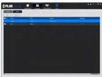
text_image
FLIR 文件(F) 编辑(E) 视图(V) 窗口(W) 帮助(H) 新建(N) 打开(O) 保存(S) 重命名(M) 粘贴(P) 重命名(R) 复制(C) 粘贴(P)... Ctrl+Alt+Alt+Alt+Alt+Alt+Alt+Alt+Alt+Alt+Alt+Alt+Alt+Alt+Alt+Alt+Alt+Alt+Alt+Alt+Alt+Alt+Alt+Alt+Alt+Alt+Alt+Alt+Alt+Alt+Alt+Alt+Alt+Alt+Alt+Alt+Alt+Alt+Alt+Alt+Alt+Alt+Alt+Alt+Alt+Alt+Alt+Alt+Alt+Alt+Alt+ Alt+F 关闭(C) 取消(C) 帮助(H) 新建(N) 打开(O) 保存(S) 重命名(M) 粘贴(P) 重命名(R) 复制(C) 粘贴(P) Ctrl+Alt+Alt+Alt+Alt+Alt+Alt+Alt+Alt+Alt+Alt+Alt+Alt+Alt+Alt+Alt+Alt+Alt+Alt+Alt+Alt+Alt+Alt+Alt+Alt+Alt+Alt+Alt+Alt+Alt+ Alt+F 确定(O) 取消(O) 帮助(H) 新建(N) 打开(O) 保存(S) 重命名(M) 粘贴(P) 重命名(R) 复制(C) 粘贴(P) Ctrl+Alt+Alt+Alt+Alt+Alt+Alt+Alt+Alt+Alt+Alt+Alt+Alt+Alt+Alt+Alt+Alt+Alt+Alt+ Alt+F 确定(O) 取消(O) 帮助(H) 新建(N) 打开(O) 保存(S) 重命名(M) 粘贴(P) 重命名(R) 复制(C) 粘贴(P) Ctrl+Alt+Alt+Alt+Alt+Alt+Alt+Alt+Alt+Alt+Alt+ Alt+F 确定(O) 取消(O) 帮助(H) 新建(N) 打开(O) 保存(S) 重命名(M) 粘贴(P) 重命名(R) 复制(C) 粘贴(P) Ctrl+Alt+Alt+Alt+Alt+Alt+Alt+ Alt+F 确定(O) 取消(O) 帮助(H)- Configure the following settings for the user account:

text_image
Add User Add Name: Add Address: Add Address: Add Address: Add Address: Add Address: Add Address: Add Address: Add Address: Add Address: Add Address: Add Address: Add Address: Add Address: Add Address: Add Address: Add Address: Add Address: Add Address: Add Address: Add Address: Add Address: Add Address: Add Address: Add Address: Add Address: Add Address: Add Address: Add Address: Add Address: Add Address: Add Address: Add Address: Add Address: Add Address:- User Name: Enter a user name for the account.
To delete a user account:
- Click ✗ next to the user account you would like to delete. Click OK to confirm.
16.14.2 Managing Roles
Roles make it easier to manage user accounts by determining the permissions an individual user account can have. By default, a new user account is given all the permissions of the role they are assigned to.
To create a role:
- Click the Role tab.
- Click Add.

text_image
FLIR FLIR Active FLIR Active FLIR Active FLIR Active FLIR Active FLIR Active FLIR Active FLIR Active FLIR Active FLIR Active FLIR Active FLIR Active FLIR Active FLIR Active FLIR Active FLIR Active FLIR Active FLIR Active FLIR Active FLIR Active FLIR Active FLIR Active FLIR Active FLIR Active FLIR Active FLIR Passive FLIR Passive FLIR Passive FLIR Passive FLIR Passive FLIR Passive FLIR Passive FLIR Passive FLIR Passive FLIR Passive FLIR Passive FLIR Passive FLIR Passive FLIR Passive FLIR Passive FLIR Passive FLIR Passive FLIR Passive FLIR Passive FLIR Passive FLIR Passive FLIR Passive FLIR Passive FLIR Passive FLIR Passive FLIR Active- Configure the following settings for the role:
To delete a user account:
- Click next to the role you would like to delete. Click OK to confirm.
16.15 General
The General menu is where you can configure application settings for the client software.
To access the General menu:
- Click and then click
16.15.1 Basic
The Basic menu contains general settings for the client software.
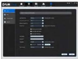
text_image
FLIR Size Parameters Parameters Model Name: FLIR Size: 250 Resolution: 16.0 Color Mode: RGB Color: 0% Color: 0% Color: 0% Color: 0% Color: 0% Color: 0% Color: 0% Color: 0% Color: 0% Color: 0% Color: 0% Color: 0% Color: 0% Color: 0% Color: 0% Color: 0% Color: 0% Color: 0% Color: 0% Color: 0% Color: 0%The Basic menu contains the following settings:
- Log Saved Time: Select the number of days you would like the client to save log entries.
- Instant Playback Time: Select the number of minutes the system will go back when you start an instant playback.
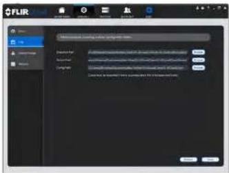
text_image
FLIR 1. Microsoft Excel 对象 2. Microsoft Excel 对象 3. Microsoft Excel 对象 4. Microsoft Excel 对象 5. Microsoft Excel 对象 6. Microsoft Excel 对象 7. Microsoft Excel 对象 8. Microsoft Excel 对象 9. Microsoft Excel 对象 10. Microsoft Excel 对象 11. Microsoft Excel 对象 12. Microsoft Excel 对象 13. Microsoft Excel 对象 14. Microsoft Excel 对象 15. Microsoft Excel 对象 16. Microsoft Excel 对象 17. Microsoft Excel 对象 18. Microsoft Excel 对象 19. Microsoft Excel 对象 20. Microsoft Excel 对象 21. Microsoft Excel 对象 22. Microsoft Excel 对象 23. Microsoft Excel 对象 24. Microsoft Excel 对象 25. Microsoft Excel 对象 26. Microsoft Excel 对象 27. Microsoft Excel 对象 28. Microsoft Excel 对象 29. Microsoft Excel 对象 30. Microsoft Excel 对象 31. Microsoft Excel 对象 32. Microsoft Excel 对象 33. Microsoft Excel 对象 34. Microsoft Excel 对象 35. Microsoft Excel 对象 36. Microsoft Excel 对象 37. Microsoft Excel 对象 38. Microsoft Excel 对象 39. Microsoft Excel 对象 40. Microsoft Excel 对象 41. Microsoft Excel 对象 42. Microsoft Excel 对象 43. Microsoft Excel 对象 44. Microsoft Excel 对象 45. Microsoft Excel 对象 46. Microsoft Excel 对象 47. Microsoft Excel 对象 48. Microsoft Excel 对象 49. Microsoft Excel 对象 50. Microsoft Excel 对象 51. Microsoft Excel 对象 52. Microsoft Excel 对象 53. Microsoft Excel 对象 54. Microsoft Excel 对象 55. Microsoft Excel 对象 56. Microsoft Excel 对象 57. Microsoft Excel 对象 58. Microsoft Excel 对象 59. Microsoft Excel 对象 60. Microsoft Excel 对象 61. Microsoft Excel 对象 62. Microsoft Excel 对象 63. Microsoft Excel 对象 64. Microsoft Excel 对象 65. Microsoft Excel 对象 66. Microsoft Excel 对象 67. Microsoft Excel 对象 68. Microsoft Excel 对象 69. Microsoft Excel 对象 70. Microsoft Excel 对象 71. Microsoft Excel 对象 72. Microsoft Excel 对象 73. Microsoft Excel 对象 74. Microsoft Excel 对象 75. Microsoft Excel 对象 76. Microsoft Excel 对象 77. Microsoft Excel 对象 78. Microsoft Excel 对象 79. Microsoft Excel 对象 80. Microsoft Excel 对象 81. Microsoft Excel 对象 82. Microsoft Excel 对象 83. Microsoft Excel 对象 84. Microsoft Excel 对象 85. Microsoft Excel 对象 86. Microsoft Excel 对象 87. Microsoft Excel 对象 88. Microsoft Excel 对象 89. Microsoft Excel 对象 90. Microsoft Excel 对象 91. Microsoft Excel 对象 92. Microsoft Excel 对象 93. Microsoft Excel 对象 94. Microsoft Excel 对象 95. Microsoft Excel 对象 96. Microsoft Excel 对象 97. Microsoft Excel 对象 98. Microsoft Excel 对象 99. Microsoft Excel 对象The File menu contains the following options:
- Snapshot Path: Click Browse to select the default folder to save snapshots.
- Record Path: Click Browse to select the default folder to save video recordings.
- Config Path: Click Browse to select the folder where the client will save software config files.

Click Save to save setting changes.
PC Users: You may need to run the client software as admin to save files to enable snapshot or video recording.
16.15.3 Alarm Prompt
The Alarm Prompt menu allows you to configure audio alerts. The client will play audio alerts when events occur. You can replace the default sounds with any .wav file.

You must configure alarms in the Alarm CFG menu before the client will play alarm sounds.
- Motion Detect: Select or preview the sound that will play for motion detection.
• Video Loss: Select or preview the sound that will play for video loss alarms. - Disk Full: Select or preview the sound that will play for disk full alarms.
- Disk Error: Select or preview the sound that will play for disk errors.
- External: Select or preview the sound that will play for external alarms (triggered by
sensor devices, which may not be supported on all systems). - E-map flashes when alarm occurs: If the camera has alarms enabled and is added
to an e-map, a appears on the e-map when an event occurs.

NOTE
Click Save to save changes.
16.15.4 Version
The Version menu shows you which version of the client software you are using. It is recommended to always run the latest version of the software. To find the latest version of the client software, visit www.flir.com/security/pro, search for the model number of your product, click on your product in the search results, and click on the Downloads tab
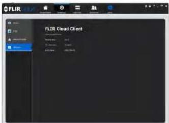
text_image
FLIR Cloud Client FLIR Cloud ClientConnecting to your System Using Smartphone or Tablet Apps
The system is compatible with iPhone, iPad and Android devices.
| Platform App Name Get App | From | |
| iPhone/iPad FLIR CloudTM Apple | App Store | |
| Android FLIR CloudTM Google Play | Play Store |
See www.flir.com/security/pro for the latest list of supported apps and devices.
17.1 iPhone
FLIR Cloud™ is an iPhone app that allows you to remotely view your system.
17.1.1 Prerequisites
- Connect your system to your router using an Ethernet cable (included).
- Make sure to upgrade your system to the latest firmware version. You must have the latest firmware and mobile apps to connect to the system over the Internet.
| NOTE |
| The app will ask for permission to send push notifications and to access Photos. It will only se cations if you enable motion-activated push notifications in the Push Config menu. It needs acc Photos to save snapshots and video clips to the local storage on your mobile device. |
17.1.2 Connecting to your System on iPhone
- Download FLIR Cloud™ for free from the App Store.
- Tap on the FLIR Cloud™ icon() to start the app.
- Tap Sign up and enter your email address and password to create a new account.

text_image
EXAMPLE 1 Screen Off Scene Regular Mode Device 0 2 Name: 1D Systems Device ID: In 8/8/142369 3 Client Port: 375000 4 Deserms: admin 5 Password: ****** Live Item Sub > Product Sub > CONNECT5.1. Tap Scan QR Code and line up the QR code on the top of your system using the camera on your mobile device.
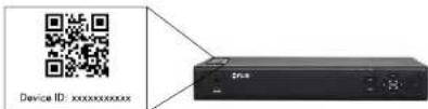
text_image
Device ID: xxxxxxxxxxxxxOR
Under Device ID, manually enter the Device ID printed on the label.
5.2. Name: Choose a name for your system of your choice.
5.3. Client Port: Enter the Client Port (default: 35000).
5.4. User Name: Enter the system's User Name (default: admin).
5.5. Password: Enter the system's Password (default: 000000).
- Tap Connect. You will be prompted to change the system password.
Live View Overview

text_image
Live View ① ② ③ ④ ⑤ ⑥ ⑦ ⑧ ⑨- Menu: Tap to bring up the Menu.
- Display Area: Double-tap to open a channel in full screen. Swipe left or right to select a different page of channels.
- Pages: Shows the number of pages available and highlights the currently selected page.
- Split: Select the split-screen layout.
- Snapshot: Tap to take a snapshot from the currently selected channel.
- Control Bar: Contains the following options. Swipe left or right to access more options.

- Tap to open PTZ controls.
PTZ Controls
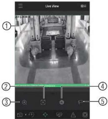
text_image
Live View ① ② ③ ④ ⑤- Live Display: Swipe to move the camera. Pinch to zoom in/out.
- Focus: Tap to show focus controls
- Zoom: Tap to show zoom controls.
- Iris: Tap to show iris controls.
- Goto preset: Tap to access preset controls. Then use the sliders to select a preset and then tap the checkmark to goto the preset.

NOTE
Local Files Overview

text_image
Screenshot of a surveillance camera interface with numbered UI elements and a display screen showing a green progress bar.- Menu: Return to Menu.
- Files: Tap to open files.
- File Type: Tap the options to select video files or snapshots.
- Options: Tap to delete or export files to your device's local storage.

Exported snapshots and video files are saved to the Photos app. Video files are saved to MP4 format.
17.1.6 Using Playback Mode on iPhone
You can access recorded video on your system using your iPhone.
| NOTE |
| You must enable Sub Stream Recording to use playback mode on mobile devices. |
-
Select the date then the start and end times to playback.
-
Use the on-screen controls to control playback.
Playback Controls

text_image
Screenshot of a photo editing interface with numbered UI elements and a central scene showing office equipment and a monitor.4.1. Display Area: Double-tap to open in full-screen.
4.2. Play/pause.
4.3. Time Bar: Tap inside the bar to fast forward or rewind.
4.4. Previous: Select previous video file.
4.5. Next: Select next video file.
4.6. Snapshot: Tap to take a snapshot from the selected camera.
4.7. Stop All: Stop playback on all channels.
4.8. Not supported.
4.9. Manual Record: Tap to start/stop recording to your mobile device's local storage.
410 Fast

text_image
OK Help Cancel Help OK Help Add Add Add Add Add Add Add Add Add Add Add Add Add Add Add Add Add Add Add Add Add Add Add Add Add Add Add Add Add Add Add Add Add Add Add Add Add Add Add Add Add Add Add Add Add Add Add Add Add Add Add Add Add Add Add Add Add Add Add Add Add Add Add Add Add Add Add Add + OK Add + Add Add + Add Add + Add Add + Add Add + Add Add + Add Add + Add Add + Add Add + Add Add + Add Add + Add Add + Add Add + Add Add + Add Add + Add Add + Add Add + Add Add + Add Add + Add Add + Add Add + Add Add + Add Add + Add Add + Add Add + Add Add + + OK Add + + Add Add + + Add Add + + Add Add + + Add Add + + Add Add + + Add Add + + Add Add + + Add Add + + Add Add + + Add Add + + Add Add + + Add Add + + Add Add + + Add Add + + Add Add + + Add Add + + Add Add + + Add Add + + Add Add + + Add Add + + + Next Step 100% Next Step 100% Next Step 100% Next Step 100% Next Step 100% Next Step 100% Next Step 100% Next Step 100% Next Step 100% Next Step 100% Next Step 100% Next Step 100% Next Step 100% Next Step 100% Next Step 100% Next Step
NOTE
Your cameras must have motion detection activated to receive push notifications.
To enable Push Notifications:
-
Tap ☐ to access the Menu, and then tap Push Config.
-
Tap the system you would like to configure.
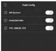
- Tap Motion Detect and then check each channel you would like to receive push notifications from.

text_image
lakeside.mydshow-fir.co Period(Day) 365 Push type Video Motion Detect Main Lobby Fireplace Main Lobby South Door Main Lobby West Main Lobby East Starwell - East Starwell - West Upper Starwell - East Users Starwell - West- Tap to save changes. You will now receive a notification when one of the selected cameras detect motion.
17.1.8 Using the Event List
The Event List menu shows a list of events that were sent to your device via push notifications.

NOTE
You must configure push notifications before you can use the Event List.
To access the Event List:
- Tap ☐ to access the Menu, and then tap Event List.
Event List Overview

text_image
Event List 12-12 08:10:09 Motion Detect > Channel 11 lakeside.mydina-fir.c > 12-12 08:09:35 Motion Detect > Channel 10 lakeside.mydina-fir.c > 12-12 08:09:25 Motion Detect > Channel 10 lakeside.mydina-fir . 12-12 08:08:13 Motion Detect > Channel 9 lakeside.mydina-fir.com- Events: Shows the details of each motion detection event. Tap the event to view the video or snapshot.
- Delete All: Tap to delete all events in the Event List.

text_image
NOTE To delete a single event, swipe it to the left and then tap Delete. Event List 12.08.08.23 Motion Detect > Channel 9 lakeside myddos-fir.com Delete 12-12.08.08.13 Motion Detect > Channel 9 lakeside myddos-fir.com- View: Tap to view the video or snapshot for the selected event.
17.1.9 Using Favorites
Favorites allows you to select a group of cameras as a favorite. You can then quickly bring up the group of cameras in Live View without having to individually select each camera.
To use Favorites:
- Select the cameras you would like to add to the group to save changes.

text_image
High priority HD system CAM 5 CAM 7 CAM 3 CAM 4 CAM 5 CAM 6 CAM 7 CAM 8 minutes mydrolife.com m0330
NOTE
To delete cameras that have been added to the group, select the group in the group list. Then, swipe left and tap Delete.
To open Favorites in Live View:
- Tap ☐ to access the Menu, and then tap Live View.
- Tap 🙏, and then tap to open the group.

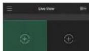
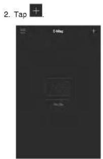
text_image
2. Tap + 5-Mep +-
Select a .jpg image on your mobile device.
-
Press 🎨 and select a camera. Drag the camera on the screen to place it on the map. Repeat to add additional cameras.

- Select the E-Map in the Device List.

text_image
Device List E-Mail Home 9 Device HD System nsaturation 162.168 50:123 (ORANGE)- Tap the camera or cameras to select and then tap Connect to open the cameras.

text_image
Home CONNECTTo delete a system:
-
Tap the system you would like to delete.
-
Tap 📄. Tap OK to confirm.

17.1.12 Adding Devices Using an IP or DDNS Address (Advanced)
The app can connect directly to a device via the IP address or DDNS address as an optional advanced connectivity method or for systems that do not support FLIR Cloud™.
Prerequisites:
• The device you are connecting to must be connected to the Internet.
- You must port forward the HTTP Port (default: 80) and Client port (35000) on your router to the device's local IP address.
- To ensure connectivity, it is highly recommended to register for a free DDNS domain to use with your system.
• For more information on port forwarding and DDNS, visit www.flir.com/security/pro.
To add a device using an IP or DDNS address:

text_image
1. Tap then + Live View Device Unit- Configure the following:
EXAMPLE
- Tap Connect. You will be prompted to change the system password.
- Enter a new 6 character password and tap OK. This password will be used to log on to your system from now on.
- The app opens in Live View and streams video from your cameras.
17.2 iPad
FLIR Cloud™ is an iPad app that allows you to remotely view your system.
17.2.1 Prerequisites
- Connect your system to your router using an Ethernet cable (included).
- Make sure to upgrade your system to the latest firmware version. You must have the latest firmware and mobile apps to connect to the system over the Internet.
| NOTE |
| The app will ask for permission to send push notifications and to access Photos. It will only se cations if you enable motion-activated push notifications in the Push Config menu. It needs acc Photos to save snapshots and video clips to the local storage on your mobile device. |
17.2.2 Connecting to your system on an iPad
- Install FLIR Cloud™ for free from the App Store.
-
Tap on the FLIR Cloud™ icon) to start the app.
-
Tap then
-
Tap Device Manager.
-
Tap Add.
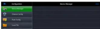
EXAMPLE
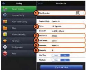
text_image
Setting C:\Users\Storage File\New Device 1 Start Sampling 2 Register Mode: Desktop 13 Name: H8 Systems 3 Studio ID: InDB943436b 4 NewPort: 30000 5 User Name: admin 6 Password: ****** 7 Channels: 8 List View: 9 Playback: Start Live View6.1. Tap Start Scanning and line up the QR code on the top of the system using the camera on your device.
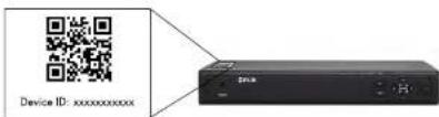
text_image
Device ID: xxxxxxxxxxxxOR
Under Device ID, manually enter the Device ID printed on the label.
6.2. Name: Choose a name for your system of your choice.
6.3. Client Port: Enter the Client Port (default: 35000).
6.4. User Name: Enter the system's User Name (default: admin).
Live View Overview

text_image
Camera navigation interface with numbered UI elements for tracking and viewing operations- Display area: Double-tap to open camera in full screen.
- Favorites: Slide to select favorites.
- Disconnect: Disconnect from all open cameras.
- Add to favorites: Add the current view to favorites.
- Snapshot: Tap to take a snapshot from the currently selected channel.

NOTE
You can view or share snapshots using the Photos app.
- Change display view.
- Not supported.
- Manual record: Tap to start/stop manual recording from this channel.
-
Not supported.
-
Slide the middle controls to the right to access PTZ controls.
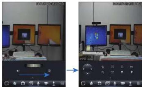
text_image
Screenshot of a video editing interface showing two identical computer monitors with UI controls and playback controls, labeled 'PPTD Drive' in Chinese.PTZ Controls
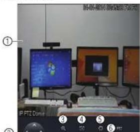
text_image
Screenshot of a computer setup with labeled monitor screens and a keyboard, showing numbered UI elements.
NOTE
You must enable Substream Recording to use playback mode on mobile devices.
To use Playback Mode:
- From Live View tap then
- In Portrait Mode: Tap +, select the start time and end time for your search, and select the camera you would like to playback.
OR
In Landscape Mode: Select the start time and end time for your search, and drag the camera you would like to playback to the display area.

text_image
Security camera interface screenshot showing vehicle detection and navigation panels with Chinese text labels- Use the playback controls.
Playback Controls
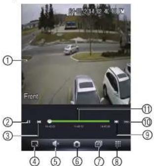
text_image
前方 2:14:02:40:13:00 Front ① ② ③ ④ ⑤ ⑥ ⑦ ⑧ ⑨ ⑩ ⑪- Display area: Double-tap to open camera in full screen.
- Play/pause.
- Previous file.
- Disconnect: Disconnect from the currently selected camera.
- Not supported.
- Snapshot: Tap to take a snapshot from the currently selected camera.
- Change display view.
- Menu.
- Next file.
- Time range: Tap to change the range of time shown in the time bar.
- Time Bar: Tap inside the bar to fast forward or rewind.

NOTE
- Tap a video file to open it.

text_image
Configuration Device Manager Channel Config Radio Config Local File Radio-set Config FlashSet Local Config Help Local File 201404231-1-15/03.dbv 20140423-1-15/03.dbvTo delete videos:
-
Tap Edit.
-
Select the videos you would like to delete and up
17.2.7 Enabling Push Notifications
You can have the app send push notifications to the notifications area on your device where one of your cameras detects motion. Once you have received a push notification, you can

text_image
FLIFT Cloud RLP Cloud H2_Server Channel 1 Bluetooth Cloud 2014-04-03 16:13:09 RLP Cloud H2_Server Channel 1 Bluetooth Cloud 2014-04-03 16:13:88 RLP Cloud H2_Server Channel 1 Bluetooth Cloud 2014-04-03 16:12:47
NOTE
Your cameras must have motion detection activated to receive push notifications.
To enable Push Notifications:
- From live view, tap then


-
Tap Push Config.
-
Tap the slider for the system you would like to configure.

- Tap Motion Detect then check each channel you would like to receive push notifications from.

text_image
Configuration Device Manager Channel Config Pute Config Local File Baby-net Config HostCount Local Config Help Pute Config HD System Pencil: no Stop Type: Playbox HKEY MODE1 PHASE CAM2 CAM3 CAM4 CAM5 CAM6 CAM7 CAM8 Survey Hit at- Under Type, select Playback to attach a video file with each push notification. Or, select Picture to attach a still image of the camera that detected motion.
- Tap OK to save changes. Whenever the selected cameras detect motion, you will receive a notification.
17.2.8 Using the Event List
The Event List menu shows a list of events that were sent to your device via push notifications.
17.2.9 Using Favorites
Favorites allows you to select a group of cameras as a favorite. You can then quickly bring up the group of cameras in Live View without having to individually select each camera.
To create favorites:
-
In Live View, lap to save the cameras that are currently open as a favorite.
-
Enter a name for the favorite and tap OK.
To open favorites in Live View:
• In Live View, slide the dial to cycle through favorites.

text_image
Street photo with visible store signboards and vehicle detection bounding boxesTo edit favorites:
-
From live view, tap then
-
Tao Favorites.
17.2.10 Using the E-Map
E-Map allows you to place cameras over a still image. For example, you can use the E-Map to create a virtual map of your cameras over a floor plan of your home or business.
To add an E-Map:

- Tap Add.

- Select a .jpg image file on your mobile device.

text_image
Photo Camera Roll 1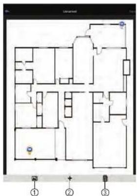
text_image
Floor plan diagram with numbered annotations and control points, likely from a game or game interface4.1. Select Image: Select a different image file to use for your E-Map.
4.2. Add Camera: Tap + to select cameras to add to your E-Map. Then drag the
camera to place it on the E-Map.
4.3. Delete E-Map.
- When you are finished editing the E-Map, tap Save and enter a name for the E-Map to save changes.
To open cameras using the E-Map:
- In live view, tap + on an empty display window and select the E-Map.

- Tap a camera from the E-map to open.

text_image
Screenshot of a mobile app interface displaying a floor plan with location markers and navigation controls17.2.11 Using the Device Manager
Device Manager allows you to manage your systems.
To access Device Manager:
- From live view, tap then
- Tap Device Manager.
To delete a system: - Tap the system to select it.
- Tap ☐. Tap Yes to confirm.

- You must port forward the HTTP Port (default: 80) and Client port (default: 35000) on your router to the device's local IP address.
- To ensure connectivity, it is highly recommended to register for a free DDNS domain to use with your system.
- For more information on port forwarding and DDNS, visit www.flir.com/security/pro.
To add a device using an IP or DDNS address:
-
Install FLIR Cloud™ for free from the App Store.
-
Tap on the FLIR Cloud™ icon to start the app.
-
Tap then
-
Tap Device Manager.
-
Tap Add.
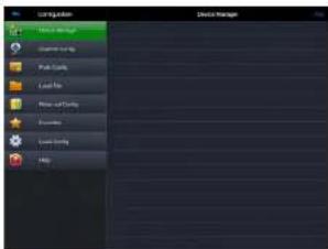
text_image
Edit Edit Admin Delete Delete Save As Save As Save As Save As Save As Help- Configure the following:
EXAMPLE

6.7. Channel Amount: Enter the number of channels your system has.
- Tap Start Live View. You will be prompted to change the system password.
- Enter a new 6 character password and tap OK. This password will be used to log on
to your system from now on. - The app opens in Live View and streams video from all connected cameras.
17.3 Android
FLIR Cloud™ allows you to remotely view your system on Android devices.
17.3.1 Prerequisites
- Connect your system to your router using an Ethernet cable (included).
- Make sure to upgrade your system to the latest firmware version. You must have the latest firmware and mobile apps to connect to the system over the Internet.

NOTE
For the latest list of supported apps and devices, visit www.flir.com/security/pro.
17.3.2 Connecting to your System on Android
- Download FLIR Cloud™ for free from the Google Play Store.
- Tap on the FLIR Cloud™ icon() to start the app.
- Tap Sign up and enter your email address and password to create a new account.
- Tap 📋 then +


- Configure the following:

5.2. Name: Choose a name for your system of your choice.
5.3. Client Port: Enter the Client Port (default: 35000).
5.4. User Name: Enter the system's Username (default: admin).
5.5. Password: Enter the system's Password (default: 000000).
-
Tap Connect. You will be prompted to change the system password.
-
Enter a new 6 character password and tap OK. This password will be used to log on to
your system from now on.

- The app opens in Live View and streams video from your cameras.
17.3.3 Live View Interface
You can use FLIR Cloud™ in portrait and landscape mode.
Live View Overview

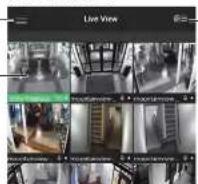


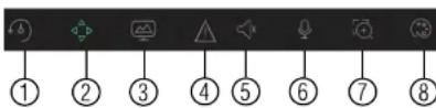
6.1. Quick Playback: Tap to start/stop quick playback.
6.2. PTZ Controls: Open/close PTZ controls. PTZ camera required (not included).
6.3. Streaming Quality: Open/close streaming quality panel.
6.4. Not supported.
6.5. Not supported.
6.6. Not supported.
6.7. Digital Zoom: Tap to activate digital zoom mode. Pinch to zoom in/out.
6.8. Color Settings: Tap to access color controls for the currently selected camera.
-
Manual record: Tap to start/stop manual recording.
-
Access Favorites.
-
Connect/disconnect all: Connect to/disconnect from all previously added cameras.
-
Device List: Tap to open a list of devices. You can use the Device List to open multip systems or cameras at once.
17.3.4 Controlling PTZ Cameras
If you have PTZ cameras (not included), you can control them from the app.
To control PTZ cameras:
-
Tap the display area the PTZ camera is connected to.
-
Tap to open PTZ controls.
PTZ Controls

- Iris: Tap to show iris controls.
- Goto preset: Tap to access preset controls. Then use the sliders to select a preset and then tap the checkmark to goto the preset.
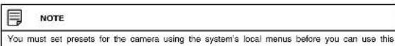
17.3.5 Viewing Snapshots and Videos with Local Files
If you have saved snapshots or videos using the app, you may open them with Local Files To access Local Files:
- Tap to access the Menu, and then tap Local Files.

text_image
Screenshot of a surveillance camera interface with numbered UI elements for tracking and navigation- Menu: Return to Menu.
- Files: Tap to open files.
- File Type: Tap the options to select video files or snapshots.
-
Options: Tan to share delete or export files to your device's local storage
-
Tap + and select a channel to playback.
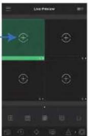
text_image
Live Preview +-
Select the date then the start and end times to playback.
-
Use the on-screen controls to control playback.
Playback Controls
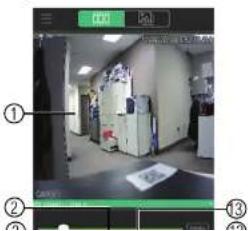
text_image
Screenshot of a surveillance camera interface showing a room with labeled components and a green screen displaying a document.17.3.7 Enabling Push Notifications
You can have the app send push notifications to the notifications area on your device when one of your cameras detects motion. Once you have received a push notification, you can select it to open live video or a snapshot attachment from the camera that detected motion

text_image
9:51 WED PHELLS 2 2014 04 02 09:51:40 MILKAN EBITDA HCD System 2nd - Overcast WED PHELLS BELL
NOTE
Your cameras must have motion detection activated to receive push notifications.
To enable Push Notifications:
-
Tap ☐ to access the Menu, and then tap Push Config.
-
Tap the system you would like to configure.
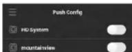
- Tap Motion Detect and then check each channel you would like to receive push notifications from.
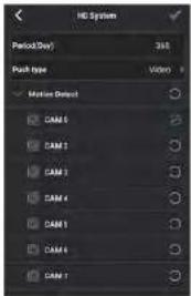
text_image
HD System Period(Day): 348 Push type: Video Motion Detect CAM 1 CAM 2 CAM 3 CAM 4 CAM 5 CAM 6 CAM 7-
Under Push type, select Video to attach a video clip to each push notification. Or, select Image to attach an image to each push notification.
-
Tap √ to save changes. You will now receive a notification when one of the selected cameras detect motion.
17.3.8 Using the Event List
The Event List menu shows a list of events that were sent to your device via push notifications.

To access the Event List:
-
- Tap to access the Menu, and then tap Favorites.
- Tap a group to configure an existing group.

text_image
NOTE Tap to create a new group and then enter a name for the new group.- To add cameras to the group, up.
- Select the cameras you would like to add to the group into save changes.
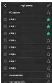
text_image
High priority HD System CAI 5 CAI 2 CAI 3 CAI 4 CAI 5 CAI 6 CAI 7 CAI 8 mountainView 190. TSS 01.122
text_image
NOTE To delete cameras that have been added to the group, select the group in the group list. The and hold to delete cameras from the group.To open Favorites in Live View
17.3.10 Using the E-Map
E-Map allows you to place cameras over a still image. For example, you can use the E-Map to create a virtual map of your cameras over a floor plan of your home or business.
To add an E-Map:
- Tap ☐ to access the Menu, and then tap E-Map.
- Tap

text_image
E-Map No file- Select a .jpg image on your mobile device.
- Press 🎨 and select a camera. Drag the camera on the screen to place it on the map. Repeat to add additional cameras.
- Select the E-Map in the Device List.
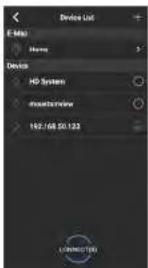
text_image
E-Mail Home 9 Device HD System Mounterview 162.168 50.123 CONNECTED- Tap the camera or cameras to select and then tap Connect to open the cameras.

text_image
Floor plan diagram with labeled rooms and directional arrows, including a highlighted section labeled 'A'To delete a system:
-
Tap the system you would like to delete.
-
Tap 📄. Tap OK to confirm.
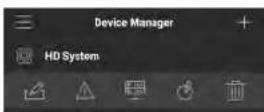
17.3.12 Adding Devices Using an IP or DDNS Address (Advanced)
The app can connect directly to a device via the IP address or DDNS address as an optional advanced connectivity method or for systems that do not support FLIR Cloud™.
Prerequisites:
• The device you are connecting to must be connected to the Internet.
- You must port forward the HTTP Port (default: 80) and Client port (default: 35000) on your router to the device's local IP address.
- To ensure connectivity, it is highly recommended to register for a free DDNS domain to use with your system.
• For more information on port forwarding and DDNS, visit www.flir.com/security/pro.
To add a device using an IP or DDNS address:
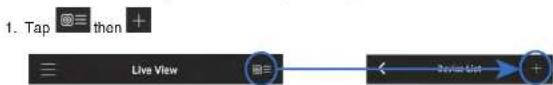
text_image
1. Tap 📋 then + Live View Device List- Configure the following:
EXAMPLE
-
Tap Connect. You will be prompted to change the system password.
-
Enter a new 6 character password and tap OK. This password will be used to log on to your system from now on.
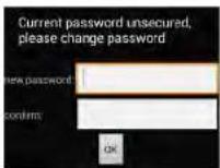
- The app opens in Live View and streams video from your cameras.
DDNS Setup (Advanced)
Free DDNS service is available as an optional connectivity method to connect to your system over the Internet.

text_image
FLIR Cloud FLIR Cloud FLIR Cloud FLIR Cloud FLIR Cloud FLIR Cloud FLIR Cloud FLIR Cloud FLIR Cloud FLIR Cloud FLIR Cloud FLIR Cloud FLIR Cloud FLIR Cloud FLIR Cloud FLIR Cloud FLIR Cloud FLIR Cloud FLIR Cloud FLIR Cloud FLIR Cloud FLIR Cloud FLIR Cloud FLIR Cloud FLIR Cloud FLIR Cloud
NOTE
Except where noted, the instructions in this section are the same on PC or Mac.
18.1 Accessing your System within a Local Network (LAN)
You can connect to your system through using the Client Software through the local area network (LAN). It is recommended to confirm connectivity over a local network before setting up your system for DDNS connectivity.

NOTE
To complete the steps below, your computer must be on the same network as your system.
- Reconnect the power adapter to power the system back on.

flowchart
graph LR
    A["Internet\n(not required for\ncal viewing)"] --> B["Router"]
    C["Computer"] --> B
    B --> D["Security System\n(may not be exactly as shown)"]
18.1.2 Step 2 of 3: Obtain the System's Local IP Address
- Right-click to open the Quick Menu and click Info. Enter the system user name (default: admin) and password (default: 000000).
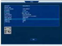
text_image
Service ID Service Name: Service Address: Service Type: Service Color: Service Name: Service Address: Service Name: Service Address: Service Name: Service Address: Service Name: Service Address: Service Name: Service Address: Service Name: Service Address: Service Name: Service Address: Service Name: Service Address: Service Name: Service Address: Service Name: Service Address: Service Name: Service Address: Service Name: Service Address: Service Name: Service Address: Service Name: Service Address: Service Name: Service Address: Service Name: Service Address: Service Name: Service Address: Service Name: 10000000000000000000000000000000000000000000000000000000000000000000000000000000000000000000000000000 R2 R3 R4 R5 R6 R7 R8 R9 R10 R11 R12 R13 R14 R15 R16 R17 R18 R19 R20 R21 R22 R23 R24 R25 R26 R27 R28 R29 R30 R31 R32 R33 R34 R35 R36 R37 R38 R39 R40 R41 R42 R43 R44 R45 R46 R47 R48 R49 R50 R51 R52 R53 R54 R55 R56 R57 R58 R59 R60 R61 R62 R63 R64 R65 R66 R67 R68 R69 R70 R71 R72 R73 R74 R75 R76 R77 R78 R79 R80 R81 R82 R83 R84 R85 R86 R87 R88 R89 R90 R91 R92 R93 R94 R95 R96 R97 R98 R99 R1002 Write down the IP Address of the system
- Log into the Client Software using the Client Software user name (default: admin) and password (default: admin) and then click Login.
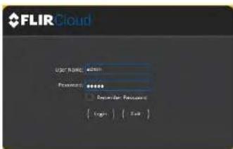
text_image
FLIR Cloud User Name: admin Password: ****** Reminder Password { Begin } { Fail }- The client scans your LAN for connected systems. Check your system (a) and click Add (b).
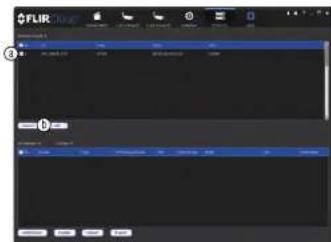
text_image
FLIR ① ②- Enter the password for your system (default: 000000) and click OK.
6 If this is the first time you are connecting you will be promoted to change the system
- Enter a new 6 character password and click OK. This password will be used to connect to your system from now on.
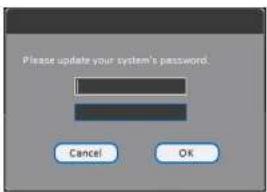
text_image
Please update your system's password. Cancel OK- Click


- Click and drag Default Group to the display window to open your cameras in live view.

text_image
FLIR Color FLIR ColorResult
To set up remote connectivity with your system, you must:
- Port forward the HTTP port (default: 80) and Client port (default: 35000) on your router to your system's IP address.
- Create a DDNS account.
- Enable DDNS on the system.
- Test the remote connection by entering your DDNS address in the client software.
18.2.1 Step 1 of 4: Port Forwarding
You must port forward the HTTP port (default: 80) and Client port (default: 35000) on your router to your system's IP address before you can remotely connect to your system. There are several methods to port forward your router:
- Use the Auto Port Forwarding Wizard (PC only) to port forward the required ports (see www.flir.com/security/pro for details). For instructions, see the Auto Port Forward Wizard manual on www.flir.com/security/pro.
- Manually port forward the required ports on your router to your system's IP address by following your router manufacturer's instructions. For more information on port forwarding, see the reference guides on www.flir.com/security/pro.

NOTE
If the above ports are not forwarded on your router, you will not be able to access your system remotely.
18.2.2 Step 2 of 4: Create a DDNS Account
To setup your free FLIR DDNS account:
- In your browser, go to http://ddns.myddns-flir.com and click Create Account.
FLIR
Login
▶ Create Account
Lost Password
-
Complete the System Information fields:
-
Product License: Select your product model from the Product License drop down menu (i.e. M4100 Series).
- : Enter the MAC address of your system.
To find the MAC address, right-click to open the Quick Menu and click Info.

text_image
Design ID: 2014-0375 Design Type: 2.6 GB/GB Parameters: 1.0 GB Parameters: 1.0 GB Application Rate: 100% (40%) Application Status: Normal Application Name: 100% Application Type: Normal Application Date: 2014-0375 OK Cancel- URL Request: Choose a URL for your DDNS connection (i.e. your name, your company or business name, or anything of your choice).
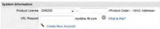
text_image
System Information Product License DNR200 - Product Code> -- Click Create New Account.
- Your account information will be sent to you at the email Address you used in Step 2. You will need this information for remote access to your system. Record your information below:
| Domain name/URL Request: | |
| Response ID: |
2.

text_image
Click and then click Network>DDNS. Network CONNECTION MINT HOLD P FILTER COMPL FTP TCP/IP SNR Type AMDOS FSR Device Name (100) Protocol OK Cancel Apply- Check Enable.
- Under Domain Name, enter the Domain Name/URL Request your received in the email after registering for DDNS.
- Under User Name, enter your DDNS User Name.
- Under Password, enter your DDNS Device password.
- Click OK to save your settings.

NOTE
Please allow 10-15 minutes for the DDNS servers to update with your new DDNS address before attempting to connect.
18.2.4 Step 4 of 4: Connect to the System's DDNS Address

NOTE
Please allow 10–15 minutes for the DDNS servers to update with your new DDNS address before attempting to connect.
- Log into the Client Software using the Client Software user name (default: admin) and password (default: admin) and then click Login.
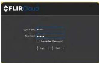
text_image
FLIR Cloud User Name: admin Password: ****** Register for Password { Login } { Exit }- Click Add Device.

text_image
FLIR Cloud Current Portion Name: FLIR Status: Normal File Name: Normal Access: Normal Add: Cancel Add: Cancel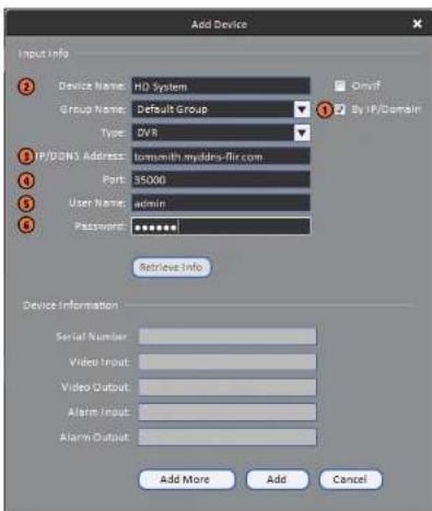
text_image
Add Device Input Info Device Name: HD System Group Name: Default Group Type: DVR IP/DNS Address: Iomewith myddrs-flir.com Port: 35000 User Name: admin Password: ****** Retrieve Info Device Information Serial Number: Video Input: Video Output: Alarm Input: Alarm Output: Add More Add Cancel5.1. Check By IP/Domain to add a system using the DDNS address.
5.2. Device Name: Choose a name for your system of your choice.
5.3. IP/DDNS Address: Enter the Domain Name/URL Request you received in the email when you registered for DDNS followed by .myddns-flir.com.

NOTE
For example, if your Domain Name!!! Request is tomorrow, actor tomorrow makes his
- Enter a new 6 character password and click OK. This password will be used to connect to your system from now on.
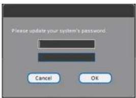
text_image
Please update your system's password. Cancel OK- Click


- Click and drag Default Group to the display window to open your cameras in live view.
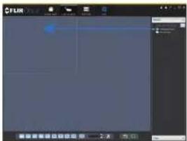
text_image
Screenshot of a software interface with a blue progress bar and Chinese text labels at the bottomCongratulations! You can now connect over the Internet to view and playback video on your computer.

RTSP Streaming (Advanced)
RTSP streaming allows you to stream video from a specific camera using a web address. It is an optional connectivity method used by 3rd party software applications.

NOTE
The instructions in this section are using VLC Media Player. VLC Media Player is a free software provided at www.videolan.org. FLIR cannot provide support for VLC Media Player or any other 3rd party software. Please contact the software vendor for technical support related to 3rd party software applications.
To connect to the video stream using VLC Media Player:
- Open VLC Media Player.
- Click Media>Open Network Stream.
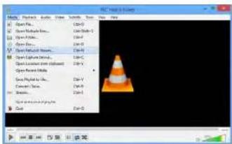
text_image
File Edit & View Open Pro... Open Pathable... Open Pathable... Open Pathable... Open Pathable... Open Pathable... Open Pathable... Open Pathable... Open Pathable... Open Pathable... Open Pathable... Open Pathable... Open Pathable... Open Pathable... Open Pathable... Open Pathable... Open Pathable... Open Pathable... Open Pathable... Open Pathable... Open Pathable... Open Pathable... Open Pathable... Open Pathable... Open Pathable... Open Pathable... Open Pathable... Open Pathable... Open Pathable... Open Pathable... Open Pathable... Open Pathable... Open Pathable... Open Pathable... Open Pathable... Open Pathable... Open Pathable... Open Pathable... Open Pathable... Open Pathable... Open Pathable... Open Pathable... Open Pathable... Open Pathable... Open Pathable... Open Pathable... Open Pathable... Open Pathable... Open Pathable... Open Pathable...-
Enter the RTSP address in the following format:
-
rtsp://
: @ : /cam/realmonitor?channel= &subtype= : The user name of the system (default: admin). : The password for the system (default: 000000). : The IP address of the system.

In order to view the RTSP stream over the Internet, you must port forward the RTSP port (default: 554) on your router to the system's IP address.
: The RTSP port (default: 554) of the system. : The number of the channel you would like to stream from. : Enter 1 for the Sub Stream of the camera or 0 for the Main Stream. It is recommended to use the Sub Stream if connecting over the Internet.
The example below shows the correct format to connect to the Sub Stream on channel
1.
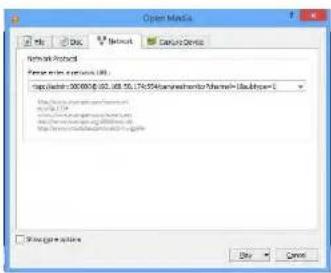
text_image
Open Media Network Protocol Server: www.100.com code: 300.000.00, 452, 488, 56, 174, 954 (www.boswimontel@mswim-100.com) http://www.boswimontel.org/100.com File Path: https://www.boswimontel.org/100.com Show log or audio Copy CancelConnecting a PTZ Camera (M4100 Series)
You can connect PTZ cameras (not included) to the system. You can use FLIR MPX or analog PTZ cameras with the system. FLIR MPX PTZ cameras can accept PTZ commands directly through the video cable. FLIR MPX PTZ cameras do not require wiring for RS485.
To connect a PTZ camera to the system:
- Connect the camera video cable to one of the Video IN ports on the system. If you have an MPX PTZ camera, it will automatically be detected and can be controlled by the DVR. If you have an analog PTZ camera, follow the steps below to set up the camera:
- You can connect the RS485 wires for analog PTZ cameras to the AB ports on the rear panel of the DVR. A is positive (+) and B is negative (-).
-
Right-click and click Main Menu. Enter the system user name (default: admin) and password (default: 000000) if prompted.
-
Click >Setting>Pan/Tilt/Zoom
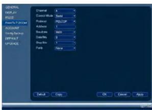
text_image
GENERAL DISPLAY RQTY OUTPUT ROOM ACCOUNT Sync/Control OFFSET UPPASE Display Mode Adder 1 Balance 345 Description 0 Display Box None Finish Copy OK Cancel Apply- Under Channel, select the channel your PTZ camera is connected to.
- Under Control Mode, select Serial. Configure the following settings for your PTZ camera.
PTZ Controls

text_image
Speed 5 Zoom Focus Iris- Direction keys: Click to pan and tilt the camera. Click SIT to stop the current action.
-
Mouse PTZ: Click to activate mouse PTZ mode. In mouse PTZ mode:
-
Click and drag to move the camera.
- Use the scroll wheel to zoom in and out.
-
Right-click to exit and return to normal PTZ controls.
-
Zoom/Focus/Iris: Click +/- to adjust the zoom, focus, and iris.
- Advanced controls: Click to open advanced PTZ controls.
- Speed: Enter the PTZ speed.
20.2 Advanced PTZ Controls
Advanced PTZ controls can be used to save camera positions and cycle through various positions, and automate camera actions.
To open advanced PTZ controls:
- Click the arrow in the PTZ control window to open advanced controls.

text_image
Speed 5 Zoom Focus Ins → Speed 5 Zoom Focus Ins No. 0Advanced PTZ controls overview:
- Autopan: Click to start autopan. During autopan, the camera will continuously pan 360°.
- Tour: Click to run the selected tour.
- Flip: Click to flip the camera 180°.
- Pattern: Click to run the selected pattern.
- Reset: Click to move the camera to the home position.
- Auto scan: Click to run the selected autoscan.
- Aux: Click to open the aux menu, where you can set up Presets, Tours, Patterns, and Auto Scans.
20.2.1 Presets
Presets will save a camera position for quick retrieval.
To add presets:
-
Click 🖱 to open the aux menu.
-
Click the Preset tab.

text_image
PAN/TLT/200M Preset Tour Pattern Border Preset 1 Set List Preset- Enter the number of the preset you want to create under Preset.
- Move the camera to the desired position and click Set.
To go to a preset:
- Under No., select the number of the preset you would like to go to and click
-
Click Add Preset.
-
Repeat steps 4 and 5 to add additional presets to the tour.
To run a tour:
- Under No., select the number of the tour you would like to go to and click
20.2.3 Pattern
Patterns automatically cycle the camera between two positions.
To create a pattern:
-
Click to open the aux menu.
-
Click the Pattern tab.

text_image
PAN TILT/ZOOM Preset Tour Pattern Border Pattern 1 Begin End- Under Pattern, enter the pattern you would like to configure.
- Move the camera into the desired start position and click Begin.
- Move the camera into the desired end position and click End.
To run a pattern:
- Move the camera into the desired left position and click Left.
- Move the camera into the desired right position and click Right.
To run an auto scan:
- Click

M4100 Series Hard Drive Installation
The system comes with a pre-installed 3.5" SATA hard drive. You can replace the hard drive with one up to a maximum size of 4TB.
21.1 Installing a Hard Drive

CAUTION
Make sure that the system is OFF and the power adapter is disconnected before removing/installing the hard drive.
To install the hard drive:
- Insert hard drive screws (4x) on the hard drive and tighten them half way.
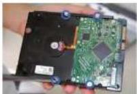
-
Power off the system, and unplug all cabling from the system.
-
Remove the rear panel screws (4x) and side panel screws (1x on each side). Remove the cover.
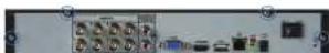

- Place the hard drive over the screw slots on the bottom of the system and then slide the hard drive into place. The SATA connectors on the hard drive should face the right side of the unit if looking at it from the rear.


- Connect the SATA power and data cable to the hard drive.

natural_image
Interior view of a computer drive bay showing internal components and wiring (no visible text or symbols)- Tum the system over carefully. Tighten the hard drive screws (4x) to secure the hard drive.

natural_image
Top-down view of a computer drive chassis with ventilation slots and a screwdriver (no visible text or labels)
CAUTION
Hold the hard drive in place when turning the system over to prevent damage to the system.
- Replace the cover and cover screws (6x).

NOTE
- Turn the system over and loosen the hard drive screws (4x), but do not remove them.

natural_image
Top-down view of a computer drive chassis with visible socket, ventilation slots, and mounting points (no text or symbols)- Disconnect the SATA power and data cable from the hard drive.

natural_image
Interior view of a computer drive bay showing internal components and wiring (no visible text or symbols)- Carefully turn the system over. Slide the hard drive and then lift it out of the system.
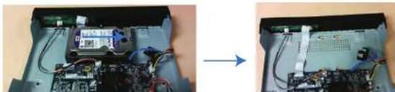
natural_image
Two views of an electronic device showing internal components and wiring, no visible text or symbols- From the Main Menu, click X and then click Storage>HDD Manager.

text_image
SINEMA HEDEMAPLES RECORDS SATA 1 Status Name: Type SATA 1 Status With HSD - Normal First Status First Group SATA 1 SATA 1 SATA 1 SATA 1 SATA 1 SATA 1 SATA 1 SATA 1 SATA 1 SATA 1 SATA 1 SATA 1 SATA 1 SATA 1 SATA 1 SATA 1 SATA 1 SATA 1 SATA 1 SATA 1 SATA 2 SATA 2 SATA 2 SATA 2 SATA 2 SATA 2 SATA 2 SATA 2 SATA 2 SATA 2 SATA 2 SATA 2 SATA 2 SATA 2 SATA 2 SATA 2 SATA 2 SATA 2 SATA 2 SATA 2 SATA 3 SATA 3 SATA 3 SATA 3 SATA 3 SATA 3 SATA 3 SATA 3 SATA 3 SATA 3 SATA 3 SATA 3 SATA 3 SATA 3 SATA 3 SATA 3 SATA 3 SATA 3 SATA 3 SATA 3 SATA 4 SATA 4 SATA 4 SATA 4 SATA 4 SATA 4 SATA 4 SATA 4 SATA 4 SATA 4 SATA 4 SATA 4 SATA 4 SATA 4 SATA 4 SATA 4 SATA 4 SATA 4 SATA 4 SATA 4 SATA 5 SATA 5 SATA 5 SATA 5 SATA 5 SATA 5 SATA 5 SATA 5 SATA 5 SATA 5 SATA 5 SATA 5 SATA 5 SATA 5 SATA 5 SATA 5 SATA 5 SATA 5 SATA 5 SATA 5 SATA 6 SATA 6 SATA 6 SATA 6 SATA 6 SATA 6 SATA 6 SATA 6 SATA 6 SATA 6 SATA 6 SATA 6 SATA 6 SATA 6 SATA 6 SATA 6 SATA 6 SATA 6- Select the hard dive you would like to format and then click Format. Click OK to confirm
- Click OK to save changes. The system will restart to complete the formatting process.
Troubleshooting
When a malfunction occurs, it may not be serious and can be corrected easily. The following describes the most common problems and solutions. Please refer to the following before calling FLIR Technical Support:
| Error | Possible Causes Solutions | |
| System is not receiving power, or is not powering up. | Cable from power adapter is loose or is unplugged. | Confirm that all cables are connected correctly.Confirm that the power adapter is securely connected to the back of the unit. |
| Power switch is set to OFF (●) position. | Confirm that the power switch is in the ON (I) position. | |
| Cables are connected, but system is not receiving sufficient power. | Confirm that the system is powered on (LED indicators on the front should be ON).If the unit is connected through a power bar or surge protector, try bypassing the bar and connecting the power directly to the wall outlet.Confirm that there is power at the outlet:Connect the power cable to another outlet.Test the outlet with another device (such as a lamp or phone charger). | |
| Hard drive is not detected by the system. | Hard drive cables are loose or not properly connected. | Remove the housing and check that hard drive cables are firmly connected. |
| There is no hard drive in the system. | Open the housing and install compatible hard drive. Make sure to format the drive after |
Troubleshooting22
| Error Possible Causes Solutions | ||
| • Mouse not detected by system. | • Mouse cable is not firmly connected to the system.Mouse is not connected to the system. | • Firmly connect the mouse cable to one of the USB ports. |
| • System needs to be reset • Power off the system (disconnect power cable). Firmly connect a USB mouse to one of the USB ports. Reconnect the power cable to the DC 12V port on the rear panel. | ||
| • There is no picture on selected channels / camera picture is not being displayed. | • Camera cables are loose or have become disconnected. | • Check the camera video cable and connections.• Disconnect and reconnect the cable at the system and at the camera.• Try moving the camera to another channel or use another cable. |
| • The system beeps at startup. | • The beep at startup is normal. | |
| • The system beeps during motion detection. | • Motion detection is enabled and the alarm buzzer is activated. | • Open the Main Menu andclick• Event>Motion-Motion Detect. Uncheck Buzzer for each channel and click Apply. |
| • I am not receiving email notifications. | • Email notification is disabled. | • Ensure you have configured email notification. For details, see 14.3.5 Configuring Email Alerts, page 54. |
| • Send Email setting not enabled in Event menu. | • Make sure that Send Email is enabled for any events you want to be notified of. | |
M4100 Series System Specifications
System
| Operating System Linux (embedded) | |
| Pontaplox Simultaneous view, record, playback, backup & remote monitoring | |
| Number of Channels 4/8/16 channel | |
Inputs/Outputs
| Video IN 4/8/16 x 1Vp-p, BNC | |
| BNC Video OUT No | |
| VGA OUT Yes | |
| HDMI Yes | |
| Audio IN | Audio IN 1 channel (RCA), supports 2-way talk |
| Audio OUT Audio OUT 1 channel (RCA), supports 2-way talk | |
| USB Port USB 2.0 x 2 (1 at the back, 1 at the front) | |
| Alarm IN None | |
| Alarm OUT | None |
| Video Output Resolution 1920x1080 (HDMI), 1280x1024, 1024x768 | |
| PTZ Control RS-485 Pelco D & P Protocol | |
Display
| Live Display 4 ch: 1, 4 | 8 ch: 1, 4, 816 ch: 1, 4, 8, 9, 16 |
| Live Display Speed 4 ch: 120 NTSC, 100 PAL | 8 ch: 240 NTSC, 200 PAL16 ch: 480 NTSC, 400 PAL |
| OSD | ON/OFF4 ch: 120fps @ 1080p/720p/960H8 ch: 240fps @ 1080p/720p/960H16 ch: 400fps @ 1080p/720p/960HPAL:4 ch: 100fps @ 1080p/720p/960H8 ch: 200fps @ 1080p/720p/960H16 ch: 400fps @ 1080p/720p/960H |
| Recording Resolution Setting Per camera for different resolutions | |
| Recording Quality Control & levels | |
| Recording Schedule By hour, by day, by recording mode, by motion, by alarm, by channel | |
| Pre Recording | Max. 30 Seconds |
| Post Recording Max. 5 Minutes | |
| Reliability Watch-Dog, auto-recovery after power failure | |
| Covert Video | Yes |
Playback
| Playback Channel Single channel or quad playback | |
| Playback Speed | Variable Max 4x |
| Playback Players Backup Player | |
| Search By Time/Date, MD & Exact search (accurate to second) | |
| Log Search Up to 1,000 lines for motion detected, configuration changes, connects/disconnects and video loss. | |
| Audio Play Yes | |
| Network Interface 10/100-Base-TX, RJ-45 | |
| Network Speed Control 96Kb ~ 4095Kb/sec. per camera | |
Storage & Archive
General
| Power Consumption Approx. 10 watts (No HDD installed) | |
| Supply Voltage 4/8 ch: 100VAC-240VAC, 12VDC, 2A, 50/60Hz | |
| Unit Dimensions (W x D x H) 12.8 x 10 x 2.2" / 325 x 255 x 55mm | |
| Unit Weight 3.3 lb / 1.5 kg (without HDD) | |
| Operating Temperature 14" ~ 131°F / -10" ~ 55°C | |
| Humidity 10 ~ 90% RH | |
Recording Resolution (Pixels) & Speed (FPS - Frames per second)
| Model | FPS (NTSC/PAL) | 960N (360x480/ 960x576) | 720P 1280x720 | 1060P 1920x1080 |
| 4ch | Total 120/100 | 120/100 120/100 | ||
| Per channel 30/25 | 30/25 30/25 | |||
| 8ch | Total 240/200 | 240/200 240/200 | ||
| Per channel 30/25 | 30/25 30/25 | |||
| 16ch | Total 480/400 | 480/400 480/400 | ||
| Per channel 30/25 | 30/25 30/25 |
As our products are subject to continuous improvement, FLIR Systems, Inc. and its subsidiaries reserve the right to modify product design, specifications, and prices without notice and without incurring any obligation. E&OE
Notices
This product has been certified and found to comply with the limits regulated by FCC, EMC, and LVD. Therefore, it is designated to provide reasonable protection against interference and will not cause interference with other appliance usage. However, it is imperative that the user follows the guidelines in this manual to avoid improper usage, which may result in damage to the product, electrical shock and fire hazard injury.
24.1 FCC/IC Notice
This equipment has been tested and found to comply with the limits for a Class B digital device, pursuant to Part 15 of the FCC Rules. These limits are designed to provide reasonable protection against harmful interference in a residential installation. This equipment generates, uses, and can radiate radio frequency energy and, if not installed and used in accordance with the instruction, may cause harmful interference to radio communications.
However, there is no guarantee that interference will not occur in a particular installation. If this equipment does cause harmful interference to radio or television reception (which can be determined by turning the equipment on and off), the user is encouraged to try to correct the interference by one or more of the following measures:
- Reorient or relocate the receiving antenna.
- Increase the separation between the equipment and receiver.
- Connect the equipment into an outlet on a circuit different from that to which the receiver is connected.
- Consult the dealer or an experienced radio or television technician for assistance.
24.2 Modification
Any changes or modifications not expressly approved by the grantee of this device could void the user's authority to operate the device.
This product is fully compliant with the European Union Restriction of the Use of Certain Hazardous Substances in Electrical and Electronic Equipment ("RoHS") Directive (2002/

Website
www.flirsecurity.com/pro
Technical Support
1-866-816-5919
Customer Service
1-866-344-4874
Copyright
© 2016. FLIR Systems, Inc.
All rights reserved worldwide. Names and marks appearing herein are either registered trademarks or trademarks of FLIR Systems and/or its subsidiaries. All other trademarks, trade names or company names referenced herein are used for identification only and are the property of their respective owners.
Legal disclaimer
Specifications subject to change without further notice. Camera models and accessories subject to regional market considerations. License procedures may apply. Products described herein may be subject to US Export Regulations. Please refer to exportquestions@fiir.com with any questions.