MH2702 - Monitor AG Neovo - Free user manual and instructions
Find the device manual for free MH2702 AG Neovo in PDF.

User questions about MH2702 AG Neovo
0 question about this device. Answer the ones you know or ask your own.
Ask a new question about this device
Download the instructions for your Monitor in PDF format for free! Find your manual MH2702 - AG Neovo and take your electronic device back in hand. On this page are published all the documents necessary for the use of your device. MH2702 by AG Neovo.
USER MANUAL MH2702 AG Neovo
natural_image
Abstract geometric pattern with diagonal black and white stripes (no text or symbols)
neovo
THE DISPLAY CHOICE OF PROFESSIONALS
TABLE OF CONTENTS
SAFETY INFORMATION
Federal Communications Commission (FCC) Notice (U.S. Only) 3
PRECAUTIONS
Notice 4
Cautions When Setting Up....4
Cautions When Using....5
Cleaning and Maintenance....6
Notice for the LCD Display....6
CHAPTER 1: PRODUCT DESCRIPTION
1.1 Package Contents 7
1.2 Installation 8
1.2.1 Installing the Stand....8
1.2.2 Adjusting the Tilt 8
1.2.3 Wall Mounting....9
1.3 Overview 10
1.3.1 Front View 10
1.3.3 Rear View....11
CHAPTER 2: MAKING CONNECTIONS
2.1 Connecting the AC Power 12
2.2 Connecting Input Source Signals....12
2.3 Cable managemen....13
CHAPTER 3: ON SCREEN DISPLAY MENU
3.1 OSD Menu Tree 14
SAFETY INFORMATION
Federal Communications Commission (FCC) Notice (U.S. Only)

This equipment has been tested and found to comply with the limits for a Class B digital device, pursuant to part 15 of the FCC Rules. These limits are designed to provide reasonable protection against harmful interference in a residential installation. This equipment generates, uses and can radiate radio frequency energy and, if not installed and used in accordance with the instructions, may cause harmful interference to radio communications. However, there is no guarantee that interference will not occur in a particular installation. If this equipment does cause harmful interference to radio or television reception, which can be determined by turning the equipment off and on, the user is encouraged to try to correct the interference by one or more of the following measures:
- Reorient or relocate the receiving antenna.
- Increase the separation between the equipment and receiver.
- Connect the equipment into an outlet on a circuit different from that to which the receiver is connected.
- Consult the dealer or an experienced radio/TV technician for help.

Changes or modifications not expressly approved by the party responsible for compliance could void the user's authority to operate the equipment.
Use only an RF shielded cable that was supplied with the display when connecting this display to a computer device.
To prevent damage which may result in fire or shock hazard, do not expose this appliance to rain or excessive moisture.
PRECAUTIONS
PRECAUTIONS

CAUTION
RISK OF ELECTRIC SHOCK DO NOT OPEN

Symbols used in this manual

This icon indicates the existence of a potential hazard that could result in personal injury or damage to the product.

This icon indicates important operating and servicing information.
Notice
- Read this User Manual carefully before using the LCD display and keep it for future reference.
- The product specifications and other information provided in this User Manual are for reference only. All information is subject to change without notice. Updated content can be downloaded from our web site at www.agneovo.com.
- To protect your rights as a consumer, do not remove any stickers from the LCD display. Doing so may affect the determination of the warranty period.
Cautions When Setting Up

Do not place the LCD display near heat sources, such as a heater, exhaust vent, or in direct
PRECAUTIONS
Cautions When Using
| Use only the power cord supplied with the LCD display. | |
| The power outlet should be installed near the LCD display and be easily accessible. | |
| If an extension cord is used with the LCD display, ensure that the total current consumption plugged into the power outlet does not exceed the ampere rating. | |
| Do not allow anything to rest on the power cord. Do not place the LCD display where the power cord may be stepped on. | |
| If the LCD display will not be used for an indefinite period of time, unplug the power cord from the power outlet. | |
| To disconnect the power cord, grasp and pull by the plug head. Do not tug on the cord; doing so may cause fire or electric shock. | |
| Do not unplug or touch the power cord with wet hands. |


WARNING:
Unplug the power cord from the power outlet and refer to qualified service personnel under the following conditions:
- When the power cord is damaged.
- If the LCD display has been dropped or the housing has been damaged.
- If the LCD display emits smoke or a distinct odor
PRECAUTIONS
Cleaning and Maintenance

Do not attempt to service the LCD display yourself, refer to qualified service personnel.
Opening or removing the covers may expose you to dangerous voltage or other risks.
Notice for the LCD Display
In order to maintain the stable luminous performance, it is recommended to use low brightness setting.
Due to the lifespan of the lamp, it is normal that the brightness quality of the LCD display may decrease with time.
When static images are displayed for long periods of time, the image may cause an imprint on the LCD display. This is called image retention or burn-in.
To prevent image retention, do any of the following:
- Set the LCD display to turn off after a few minutes of being idle.
- Use a screen saver that has moving graphics or a blank white image.
- Switch desktop backgrounds regularly.
- Adjust the LCD display to low brightness settings.
- Turn off the LCD display when the system is not in use.
Things to do when the LCD display shows image retention:
- Turn off the LCD display for extended periods of time. It can be several hours or several days.
- Use a screen saver and run it for extended periods of time.
CHAPTER 1: PRODUCT DESCRIPTION
1.1 Package Contents
When unpacking, check if the following items are included in the package. If any of them is missing or damaged, contact your dealer.
LCD Display

Stand Base Power Cord
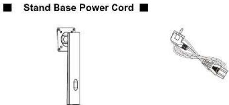
■ Quick Start Guide ■ Warranty Card ■ HDMI Cable

■ Warranty Card ■ HDMI Cable


PRODUCT DESCRIPTION
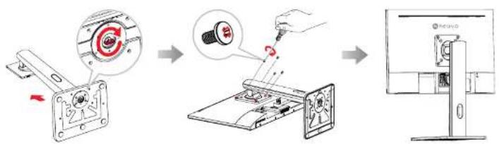
1.2 Installation
1.2.1 Installing the Stand
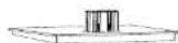
- Place the LCD display with the screen side down on a cushioned surface.
- Attach the stand to the LCD display.
a. Take out the stand and base, and lock the stand with the hand screw that comes with the base.
b. Screw the mounting bracket to the VESA holes at the rear of the LCD display.
text_image
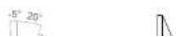
Diagram illustrating the step-by-step assembly of a mechanical device, showing component disassembly and mounting process.1.2.2 Adjusting the Tilt
The screen can be adjusted by inclining forward and backward; however, the specific adjustment depends on the specific model of the device.
PRODUCT DESCRIPTION
1.2.3 Wall Mounting
To wall mount the LCD display, do the following steps:
- Remove the base stand.
Detach the base from the base mount.
a. Place the LCD display with the screen side down on a cushioned surface.
b. Detach the stand from the base mount.

text_image
Diagram showing a hand using a screwdriver to adjust a component, with magnified view of the screw being held.- Wall mount the LCD display.
Screw the mounting bracket to the VESA holes at the rear of the LCD display.
PRODUCT DESCRIPTION
1.3 Overview
1.3.1 Front View
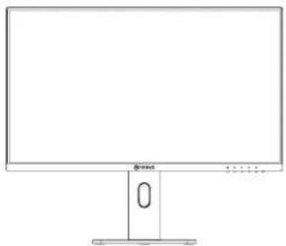
natural_image
Line drawing of a computer monitor with a stand and control panel (no text or symbols)1.3.2 Control Buttons
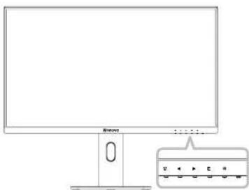
natural_image
Line drawing of a computer monitor with an inset showing a control panel (no text or symbols)PRODUCT DESCRIPTION
1.3.3 Rear View
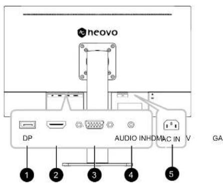
text_image
neovo DP AUDIO INHDMAC IN V GA 1 2 3 4 5
DP Input
Connect DisplayPort signals input.

HDMI Input
Connect HDMI signals input.

VGA Input
CHAPTER 2: MAKING CONNECTIONS

CAUTION:
Make sure that the LCD display is not connected to the power outlet before making any connections. Connecting cables while the power is ON may cause possible electric shock or personal injury.
2.1 Connecting the AC Power
- Connect the power cord to the AC power input at the rear of the LCD display.
- Connect the plug to a power outlet or power supply.

text_image
~ AC IN
CAUTION:
When unplugging the power cord, hold the power cord by the plug head. Never pull by the cord.
2.2 Connecting Input Source Signals
CHAPTER 2: MAKING CONNECTIONS
2.3 Cable management
After connecting the cables to the monitor, use the cable management slot to organize all cables shown below.
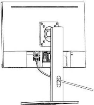
natural_image
Technical line drawing of a mechanical assembly with no visible text or symbolsCHAPTER 3: ON SCREEN DISPLAY MENU
3.1 OSD Menu Tree
| Main menu | Submenu | Third menu | Range Description | |
| Display Brightness 0-100 Adjust display brightness | ||||
ON SCREEN DISPLAY MENU
| Main menu | Submenu | Third menu | Range | Description |
| Mode Standard | ard Set to standard mode | |||
| Cinema Set to Cinema mode | ||||
| FPS Set to FPS mode | ||||
| RTS Set to RTS mode | ||||
| Eye Saver Set to Eye Saver mode | ||||
| Reture Return to the previous menu | ||||
| Exit Exit from the menu | ||||
| Color Temp. | Cool Set to Cool Color temperature | |||
| Warm Set to Warm Color temperature | ||||
| User | Red | 0-100 | Adjust the red output | |
| Green | 0-100 | Adjust the green output | ||
| Blue | 0-100 | Adjust the blue output | ||
| Return | Return to the Color Temp. menu | |||
| Exit | Exit from the whole menu | |||
| Return Return to the previous menu | ||||
| Exit Exit from the menu | ||||
| Aspect | Auto | to 4:3 | Automatically adjust picture aspect ratio | |
| 16:9 | Set the Picture Aspect to 16:9 | |||
| 4:3 Set the Picture Aspect to 4:3 | ||||
| Return | Return to the previous menu | |||
ON SCREEN DISPLAY MENU
| Main menu | Submenu | Third menu Range | Description |
| Other Power | Off On Automatically | turn off after saving | power for 1 minute |
| function of t | med switch-off | ||
| Return Return to Other men | enu | ||
| Exit Exit from the menu | |||
| Gamma Gamma1 | Set the Gamma1 | ||
| Gammar2 Set the Gamma2 | |||
| Return Return to Other men | enu | ||
| Exit Exit from the menu | |||
| Volume 0-100 | Adjust the Volume output | ||
| Adjust | Auto Adjust | ||
| Auto Color | |||
| Clock | 0-100 Adjust the picture clock to reduce vertical line noise (only for VGA) | ||
| Phase | 0-100 Adjust the picture phase to reduce horizontal noise (only for VGA) | ||
| Return Return to Other men | enu | ||
| Exit Exit from the menu | |||
| Return | |||
| Exit |
CHAPTER 4: APPENDIX
4.1 Warning Messages
When any of these warning messages appear, check the following items.
| Warning Message Cause Solution | ||
 | The LCD display cannot detect the input source signal. | √ Check if the input source is turned ON.√ Check if the signal cable is properly connected.√ Check if any pin inside the cable connector is twisted or broken. |
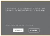 | This warning message box will only show when the menu feature setting is changed for the first time. | • Press the ACCEPT button to continue the setting changes, or press the CANCEL button to disable the setting changes.• Note: The operation may vary from different product models. |
APPENDIX
4.2 Troubleshooting
| Problems Possible | Cause and Solution |
| The power indicator light is not on | Check if the power is on.Check if the power cord is connected. |
| Impossible plug-and-play | Check if the function of plug-and-play of the device is compatible with PC.Check if the display card is compatible with the plug-and-play function.Check if the signal line 15 pin d joint bent |
| Dimming picture | Adjust brightness and contrast. |
| Flickering picture or picture with ripples | There may be electrical appliances or equipment with electronic disturbance. |
| The power indicator light is on (flickering), but the monitor has no pictures. | Check if the PC power is on.Check if the PC display card is inserted properly.Check if the signal cable of the monitor is correctly connected with the PC.Check the signal cable plug of the monitor and make sure every pin has no bending.Observe the indicator light by pressing the Caps Lock key on the PC keyboard and check if the PC is working. |
CHAPTER 5: SPECIFICATIONS
5.1 Display Specifications
| MH2402MH2702 | |||
| Panel | Panel Type | LED-Backlit TFT LCD (IPS Technology) | LED-Backlit TFT LCD (IPS Technology) |
| Panel Size 23.8" 27.0" | |||
| Max. Resolution FHD 1920 x 1080 FHD 1920 x 1080 | |||
| Pixel Pitch 0.275 mm 0.31 mm | |||
| Brightness 250 cd/m | ^2 | 250 cd/m ^2 | |
| Contrast Ratio 20,000,000 | 1 (DCR) 20,000,000:1 (DCR) | ||
| Viewing Angle (H/V) | 178°/178° | 178°/178° | |
| Display Colour | 16.7M | 16.7M | |
| Response Time | 5 ms | 5 ms | |
| Frequency (H/V) | H Freq. | 30 kHz-82 kHz | 30 kHz-82 kHz |
| V Freq. | 50 Hz-75 Hz | 50 Hz-75 Hz | |
| Input | DisplayPort | 1.2 x 1 | 1.2 x 1 |
| HDMI | 1.4 x 1 | 1.4 x 1 | |
| VGA | 15-Pin D-Sub x 1 | 15-Pin D-Sub x 1 | |
| Audio | Audio In | Stereo Audio Jack (3.5 mm) | Stereo Audio Jack (3.5 mm) |
| Internal Speaker | 1W x 2 | 1W x 2 | |
| Power Power Supply | Internal | Internal | |
| Power Requirements | AC 100-240V, 50/60 Hz | AC 100-240V, 50/60 Hz | |
| On Mode | 14W (On) 17W (On) | ||
| Standby Mode | < 0.5W | < 0.5W | |
| Off Mode | < 0.3W | < 0.3W | |
| Operating Conditions | Temperature | 0°C-40°C (32°F-104°F) | 0°C-40°C (32°F-104°F) |
| Humidity | 20%-85% (non-condensing) | 20%-85% (non-condensing) | |
| Storage Conditions | Temperature | -20°C-60°C (-4°F-140°F) | -20°C-60°C (-4°F-140°F) |
| Humidity | 5%-95% (non-condensing) | 5%-95% (non-condensing) | |
| Mounting | VESA FPMPMI | Yes (75 x 75 mm) | Yes (75 x 75 mm) |
| Stand | Tilt | -5° to 20° | -5° to 20° |
| Security | Kensington Security Slot | Yes | Yes |
| Dimensions | w/ base (W x H x D) | 541.9 x 502.3 x 200.8 mm (21.3" x 19.8" | 613.5 x 524.5 x 200.8 mm (24.2" x 20.7" x |
SPECIFICATIONS
5.2 Display Dimensions
MH2402
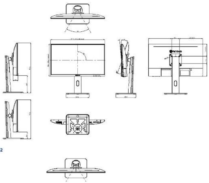
MH2702