Integration Box - Boîtier d'intégration Simplify - Free user manual and instructions
Find the device manual for free Integration Box Simplify in PDF.

User questions about Integration Box Simplify
0 question about this device. Answer the ones you know or ask your own.
Ask a new question about this device
Download the instructions for your Boîtier d'intégration in PDF format for free! Find your manual Integration Box - Simplify and take your electronic device back in hand. On this page are published all the documents necessary for the use of your device. Integration Box by Simplify.
USER MANUAL Integration Box Simplify
simplify
CLIMATE SOLUTIONS

Introduction:
Table of Contents
Introduction
Contents
The Manual contains the following sections:
Introduction 1
Table of Contents 1
Overview 2
Declaration of Conformity 5
Product description 6
General description 6
Transportation, handling and storage 7
On receipt 7
Use....9
Introduction 9
Installation.... 11
System setup....11
Extending/replacing a Sensor Box in an active installation 12
Replacing a Sensor Probe in an active installation 12
Use 13
Use of CDT Dehumidifiers with Integration Box....13
Simplify Dashboard 14
Introduction 14
Simplify Dashboard users and assigned Simplify Control Units 20
Troubleshooting 21
Simple self-help 21
For additional information....23
Appendix 24
Technical data....24
Dimensions 26
en
Introduction: Overview
Overview
Manual
This Manual describes the installation and use of the "Simplify" monitoring solution.
The Manual item number is: 055068.
Target group
The target group for this product comprises fitters, technicians as well as end-users, who need to monitor a dehumidification process and require data within a given time frame from a location presented online. (Temperature, humidity, air quality, power consumption and so on).

NOTE!
The devices must only be installed and repaired by qualified personnel.
It is the fitter's, technician's and user's responsibility to read and understand this Manual prior to initial setup and start-up of the devices.

WARNING
The devices are not intended for use by persons (including children) with impaired physical, sensory or mental capabilities, unless they are supervised or have received instructions in the use of the device by a person responsible for their safety.
Children must be supervised to ensure they do not play with the device.
Any form of maintenance other than external cleaning of the device must be performed by trained personnel.
The protection class for the devices is defined in the section on "IP class, description" on page 27.
Copyright
The Manual or parts thereof may not be copied without Dantherm's prior written consent.
Reservations
Dantherm reserves the right to make changes and improvements to the product and the manual at any time and without prior notice or obligations.
Symbols
The following symbols are used in this manual to draw attention to hazards and further relevant information.
Warning and
explanatory symbols

Introduction: Overview
System parts and description
This Manual uses the following terminologies and abbreviations in connection with the Simplify Monitoring Control System.
| Abbreviations | |
| Simplify Control Unit The Control Unit is placed centrally so that all Sensor Boxes, Integration Boxes and Relay Boxes have the best possible radio contact. | |
| Simplify Sensor Box Sensor Box that communicates wirelessly with the Control Unit. | |
| Simplify Relay Box (on/off) Up to three connected devices.Built-in MID (Measuring Instruments Directive) approved kWh counter.NOTE! National versions of the Relay Box are available. If a voltage other than 184-264 VAC or other plug connections are required:Contact Dantherm Intelligent Monitoring A/S for additional information. | |
| Simplify Integration Box CDT The integration box is installed in a Dantherm CDT Dehumidifier MKII/III.The dehumidifier can then be controlled from the Dashboard. | |
| Simplify Sensor Probe Sensor Probe that measures temperature and relative humidity.Probes are available in the following lengths: 24 cm/300 cm/2.000 cm. | |
| Simplify App for installation Smart phone application that is used for scanning and registration of the system.Supports both iOS and Android. | |
| Simplify Dashboard Online platform for presentation of data and generation of reports as well as remote con- |
en
Introduction: Overview
Recycling
The devices and the system are designed for a long service life.
Once the product reaches its end of life, recycle all physical devices in accordance with the national regulations and with due consideration for the environment.
The electrical and electronic equipment and accompanying batteries contain materials, components and substances that can be hazardous to human health and the environment if the waste is not managed properly.

NOTE!
It is important that end-users dispose of all end-of-life batteries using established recycling schemes. This makes sure that batteries are recycled in accordance with the law and do not cause unnecessary harm to the environment.
End-of-life industrial batteries can be handed over to the producer or importer who originally marketed the battery or to a manufacturer or importer from whom the end-user buys a new industrial battery.
Introduction: Declaration of Conformity
Declaration of Conformity

Dantherm®
CONTROL YOUR CLIMATE
Declaration of Conformity
Electronics
Dantherm A/S
Marienlystvej 65
DK - 7800 Skive
Declaration of following product:
Product name: Simplify control unit, Simplify sensor box, Simplify on/off relay, Simplify integration sensor
Product no.: 380000, 380003, 380005, 380006
The product is in conformity with the following directives:
2014/35/EU
Low Voltage Directive
2014/53/EU
Radio Equipment Directive
2014/30/EU
Electromagnetic Compatibility Directive
2014/29/EU
RoHS Directive
1907/2006/EC
REACH Regulation
en
Product description: General description
Product description
General description
Introduction
The Simplify monitoring solution is a Cloud-based mobile solution that permits the connection of a number of Sensor Boxes. These Sensor Boxes transmit data (temperature and relative humidity) to the Simplify Dashboard, where data can be accessed via PC, tablet or smart phone.
It is used, e.g., in places affected by water damage or in buildings that need monitoring.
- Simplify transmits data on relative humidity and temperature to the Simplify Dashboard in real time.
- Simplify can send alerts to the user.
- Simplify provides unique documentation in the form of graphs and reports.
- Simplify uses GSM and will always find the strongest GSM signal.
- Simplify works both as a stand-alone system and in combination with Dantherm CDT Dehumidifiers from the MKII series and later.
- A number of Sensor Boxes can be connected to Simplify. However, for best ease of use, we recommend the use of not more than 50 Sensor Boxes.
- Simplify will automatically start the CDT Dehumidifier once the Control Unit has established connection.
- If the 230 V supply to the Control Unit falls, the battery backup kicks in. It can maintain Simplify's normal function for up to 12 hours.
• The backup battery charges automatically once mains voltage is available again.

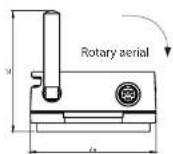
NOTE!
To ensure the best range possible, unit aerials should be in a vertical position (or as a minimum all should be in the same position), preferably placed as high as possible on all products.
Simplify uses 868 MHz radio frequency. This frequency ensures a long range, without any impediments between transmitter and receiver. Nevertheless, keep in mind that objects, walls, etc. between transmitter and receiver will reduce the range.
Transportation, handling and storage: On receipt
On receipt
Transportation, handling and storage
Check for transport damage
Step Action
1 Report all visible damage to the freight, packing or postal service company, possibly on delivery, and note down the damage on the cargo documentation.
2 Entirely remove any packaging (without using knife) and dispose of it according to local regulations.
3 Check the contents.
4 If any form of transport damage is discovered after unpacking devices, or if the shipment is defective, contact your local dealer as quickly as possible.
Contents
Overview of units to the Simplify system:

Illustration
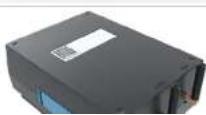
Simplify - case

natural_image
Black hard-shell case with a handle and 'simply' label on the front face (no other text or symbols visible)Simplify Control Unit
en
Transportation, handling and storage: On receipt

Illustration
Simplify Relay Box, 3 outputs
(Relay Boxes are available in different versions, for voltages other than 184-265 VAC as well as for other types of sockets).
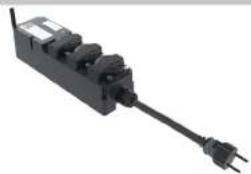
natural_image
Black electrical plug with multiple connectors and a terminal outlet (no visible text or symbols)Sensor for incorporation into CDT MII/III (option)

Illustration
Simplify integration Sensor Box for CDT MKII/III.

How to use: Introduction
How to use
Introduction
The Simplify Installation App is available for both Android (version 5.1 or later) and iOS (iOS10 or later).
Android App:
Download the Installation App via Google Play: Dantherm
or
The App looks different in App Store and in Google Play.
Once the Control Unit is connected to 230 V mains voltage, it will seek out the strongest GSM signal. However, be sure to make available GSM coverage via the 2G/2.5G network.
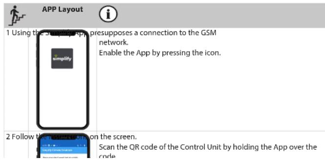
text_image
APP Layout 1 Using the App, presupposes a connection to the GSM network. Enable the App by pressing the icon. 2 Follow the App on the screen. Scan the QR code of the Control Unit by holding the App over the code.en
How to use: Introduction

APP Layout

4 Name the Control Unit.

Mark the "pencil" (iOS: mark the line NAME) and specify the address, case number, etc.
(This will be indicated on the Dashboard as the case ID).
Maximum 30 characters (UTF-8, which are the common keys found on the keyboard).
5 Confirm the scan with OK.
6 Add Sensor Box, integration sensor or Relay Box to the Control Unit
(maximum 25 characters).

Press "SENSORS" and then + (iOS "add sensor")
Scan the Sensor Box QR code and name it in the ID field (for example, location, which will be indicated on the Dashboard).
Press "ADD SENSOR"
If additional Sensor Boxes are to be installed, continue with + (iOS "add sensor").
NOTE! If Sensor Boxes from a previous installation are visible in the App, the Control Unit is not archived.
They will appear as a list in the App.
They can be deleted by pressing the Sensor Box until it is possible to press "delete", the deletion will be registered in the "Cloud" by pressing REGISTER (iOS "swipe").
Installation: System setup
System setup
Installation
Setup
| System setup | |
| 1 Connect a Control Unit to 230 V mains voltage. The Control Unit will flash orange. | |
| 2 Once the Control Unit has established GSM connection, the light will be solid ORANGE (this takes approx.120 seconds). | |
| 3 If there is no 230 V supply and backup power is activated, the Control Unit will be solid RED. | |
| 4 The Control Unit will turn on the CDT Dehumidifier once it has established contact with it (after approx. 60 seconds). | |
| 5 Place the Sensor Boxes at the desired measuring points. | |
| 6 Connect the Sensor Probe to the Sensor Box via the DIN connector click-lock (pull back for connection, as shown on the connector's plastic part). | |
| 7 Connect the Relay Box to 230 V voltage and the equipment. | |
| The Sensor Box is now on and emits 2 beeps once the Sensor Box has a sufficient battery charge and the Sensor Probe is okay.If the Sensor Probe Is defective, It will emit only 1 beep.If the batteries of the Sensor Box are dead, no sound is emitted | |
| 8 The Sensor Boxes send a signal to the Control Unit. | |
| Once the Sensor Boxes establish a connection with the Control Unit, they emit 3 short beeps indicating the connection is okay and that data is received.If the 3 beeps are not emitted, connection to the Control Unit is NOT established.Move the Sensor Box or Control Unit so that connection is established.The Sensor Box then goes into sleep mode and sends data to the Control Unit at a specified interval. (The interval is defined in the Dashboard). | |
en
Installation: Extending/replacing a Sensor Box in an active installation
Extending/replacing a Sensor Box in an active installation
An installation can be extended without powering down the Control Unit.
When a new Sensor Box is connected, scan the Control Unit QR code, press "REGISTER" in the
App, and then the Control Unit will upload every minute for the next hour. This enables quick data transfer from the connected Sensor Box.

1 Scan the Control Unit.
Press "NEXT".
Press "SENSORS".
Press + (iOS "add sensor") and scan the Sensor Box that you want to connect to the system and name it.
2 Press "ADD SENSOR". Then press "REGISTER".
The Sensor Box will then automatically be connected to the rest of the installation.
3A If a Relay Box or Integration Box is connected, they will automatically become "AC-
TIVE"!
Sensor Boxes become "ACTIVE" in the Dashboard the next time the Control Unit uploads data to the Dashboard, which happens after a few minutes.
3B If the connection is a Sensor Box, connected Sensor Probe, where the Sensor Box
becomes "ACTIVE".
Sensors become "ACTIVE" in the Dashboard the next time the Control Unit uploads
data to the Dashboard, which occurs after a few minutes.

If a Sensor Box is deleted by mistake during installation, the Sensor Box and its data will remain
in "ARCHIVE" after archiving.
Use: Use of CDT Dehumidifiers with Integration Box
Use
Use of CDT Dehumidifiers with Integration Box

NOTE!
When repairing water damage, it can be advisable to use one or more CDT Dehumidifiers and receive data from them.
This is done via the relevant CDT Dehumidifiers being scanned on a Control Unit. Data from all CDT Dehumidifiers will then be displayed on the Dashboard.
Power consumption (kW) and total power consumption (kWh) are displayed in the Dashboard for each CDT Dehumidifier and for all CDTs together.
If a CDT has a "full water container" or "technical alarm", these alarms will automatically be displayed in the Individual CDT's own box on the Dashboard with the following icons:

Technical alarm, CDT
Full water tank, CDT
en
Simplify Dashboard: Introduction
Introduction
Simplify Dashboard
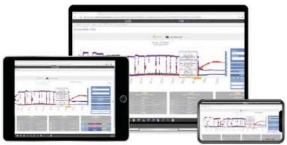
text_image
Three electronic devices displaying data dashboards and charts, including line graphs and bar charts on screens.Fig. 1
Receiving data
Data will be visible in the Dashboard when the Control Unit has uploaded data that is received from Sensor Boxes.
- The first data is received after a couple of minutes. All Sensor Boxes transmit 10 data points in the first 10 minutes, subsequent transmissions are performed at the interval selected in the Dashboard.
- Once the data from the Sensor Boxes has been read by a Control Unit, the boxes go into sleep mode. The Relay Box and Integration Box do not go into sleep mode, but report at the selected data interval.
- Sensor Boxes transmit signals to the Control Unit at the interval defined in the Dashboard.
- Battery life depends on the transmission interval and on-site radio conditions. The residual voltage of the battery of the Source Dev is displayed in the Deckboard for each Source Dev
Simplify Dashboard: Introduction
Dashboard installation view
- All Control Units associated with the user are displayed.
- If a Control Unit appears as "ACTIVE", the user can see when it was last online in the field "Last seen online".

text_image
Last seen online Status YYYY-MM-DD HH:MM:SS 2021-04-28 10:59:10 Active- The Control Unit ID code appears when you click on the QR code. This can be scanned and the user will then have remote access and e.g. be able to connect additional Sensor Boxes from the office, which can then be transported to the address and switched on.

text_image
Info MAP QR QR Code for 1048587- Clicking MAP opens Google MAP for the area, where a Control Unit is scanned and registered. Driving directions can be generated.
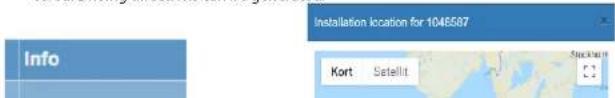
text_image
Info Installation location for 1046587 Kort Satellite
Simplify Dashboard: Introduction
CHART view
- To switch to "Chart View", click on a Control Unit and press "NEXT" or double-click the Control Unit. "HUM" (relative humidity) is then displayed by default for all Sensor Boxes linked to the Control Unit.
- Data is displayed by default for the last 14 calendar days. If all data is required, press "Load All Data". Alternatively, you can specify another date range.
- It is possible to scroll in "Chart View", after which a box will be displayed per Sensor Box with information about it such as ACTIVE/PASSIVE, Name, type, ID, DWT, HUM, PDV, TEMP, WCT, PWR, BAT as well as the most recent values tread for all parameters.
- By clicking the icon in the boxes the name of the Sensor Boxes can be changed and
saved by pressing

- The "On/Off" indication for the Relay Box or Integration Box.
- Alarms are displayed for "full water tank" or "technical error" in CDT from the Integration Box.
- "ACTIVE" means that the Sensor Box transmits data to a Control Unit.
- "PASSIVE" means that the Sensor Box does not transmit data to a Control Unit.
"SEE ALL DATA"
- "SEE ALL DATA" displays all data for the respective Sensor Box.
- By marking the desired parameters in the box for each Sensor Box, the corresponding graph is displayed following each click. The most recently received data is displayed in the colour field for the respective parameters.
As a rule, each field has a colour selected by the Dashboard. It can be edited and is used in the graph.
Abbreviation

HUM Relative humidity
TEMP Temperature
DWT Dew point
PDV Saturated vapour pressure
WCT Water content
PWR Power consumption/output
Simplify Dashboard: Introduction
- If an integration sensor or Relay Box is installed, each of these will be displayed by default under the graph with total kWh consumption per Integration Sensor and Relay Box. Total combined power consumption in kWh is displayed.
- To view current kW consumption, select PWR for each individual Integration Sensor and Relay Box.
- It is possible to generate a PDF of the graph by pressing Generate PDF
- "Save Default Chart" saves the settings in the Sensor Box and graph for the given user login.
- The REPORT GENERATOR button generates a report for the selected graph into editable Word and Excel files that contain all selected data.
- On the icon to the right of the case "NAME" it is possible to change the data range from all linked sensors from the default once every 60 minutes if so desired. The Control Unit upload Interval remains the same, but the desired data is sent to the Dashboard.
ALARM LEVELS
Indicates alarms for Sensor Boxes and recipients of alarms.
- Select "ALARM LEVELS" in the menu
- A view of all Control Units assigned to the user is displayed. Search for the installation in the search box and click on it.
- Press "ADD" opposite the desired type of alarm for the installation and/or Sensor Boxes.
- You can set an alarm for the installation, which means that recipients will be advised if equipment in the installation becomes PASSIVE.
- You can set alarms for individual Sensor Boxes for all parameters, HUM, TEMP, DWT, PWR, etc. It is possible to set both minimum and/or maximum values outside of which an alarm will be triggered.
- To set INSTALLATION ALARMS, click "add". Then set your desired delay for triggering the alarm, i.e. how long the situation must go on for in order for an alarm to be received. The more hours are selected, the fewer alarms must be expected to be received.
- To set SENSOR ALARMS, click "add". A list of all Sensor Boxes in the installation will come up.
- To view, edit or delete all alarms, click the sensor opposite the arrow and the VIEW/EDIT button or DELETE and then YES.
The alarm can be used both to receive final notification when a desired level is reached or receive
Simplify Dashboard: Introduction
ALARM from Integration Box
When an alarm is received from the Integration Box, it looks as on "Fig. 2" on page 20.
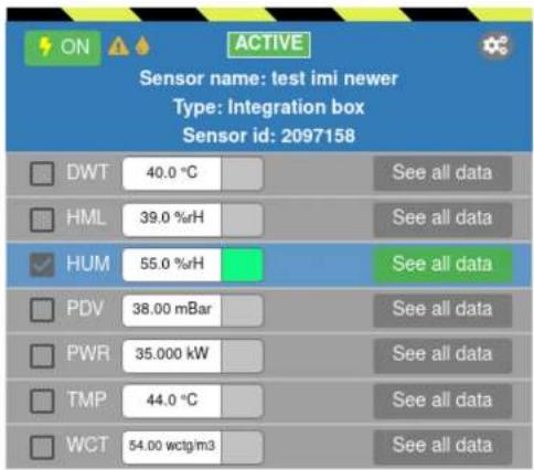
text_image
ON ACTIVE Sensor name: test imi newer Type: Integration box Sensor id: 2097158 DWT 40.0 °C HML 39.0 %RH HUM 55.0 %RH PDV 38.00 mBar PWR 35.000 kW TMP 44.0 °C WCT 54.00 wctg/m3 See all data See all data See all data See all data See all data See all dataFig. 2
DASHBOARD ON/OFF
Equipment connected to a Relay Box or Integration Box can be turned on and off directly from the Dashboard.
A Relay Box is used, for example, when other equipment than CDT is connected to an installation where you would like to collect data for power consumption (kWh) or receive power consumption alerts (kW). Likewise, you can turn off and on the equipment without visiting the address.
Simplify Dashboard: Introduction
from previous case as well as the new case will be visible in the Dashboard. The Control Unit will not start an upload every minute, which is the default for Control Units that come from archived state.
"ARCHIVE" removes data from Dashboard installation view as well as the Control Unit, whereupon the case is archived in "ARCHIVE" in the Dashboard. The cases are placed under the "ARCHIVE" function in the Dashboard.
• SCAN the QR code on the Control Unit and press "ARCHIVE"
- Press OK. The case is saved in "ARCHIVE" under the existing case name
- The Control Unit now changes name to "ARCHIVED" in the Dashboard and is ready for a new case
REPORT GENERATOR
"REPORT GENERATOR" makes it possible to create Word and Excel files containing all data from the Dashboard. All data may be freely combined for one, several or all sensors.
- Mark your desired case in the Dashboard installation view and press "NEXT" (or double-click)
- Select the data, date range, etc. that you would like to include in the report in "Chart View". The graph is updated for each selection
- Once the desired graph is created, select "REPORT GENERATOR" in the menu
- "REPORT GENERATOR" creates the graph and displays a view of the selected data. Here you can make selections again.
- Press"GENERATE"
- "REPORT GENERATOR" now creates a zip file containing both a Word and Excel file as well as a PDF file with the case name.
RELAY BOX

text_image
Diagram showing electrical connection with a power outlet, plug, and control unit labeled with numbered componentsen
Simplify Dashboard: Simplify Dashboard users and assigned Simplify Control Units
Simplify Dashboard users and assigned Simplify Control Units
Administrator access
Dantherm Intelligent Monitoring A/S can offer to devise and maintain a user hierarchy.

text_image
simplify Users Create User User Name Name Business Company Name Final HomeThe Company User and Supervisor User roles can create, edit and delete a user hierarchy with 3 levels: via the top menu "Admin";
- Company Level with all company Control Units.
- Supervisor level with specifically assigned systems for own use + systems in users who are supervised.
- Users who use assigned systems.
Company level: User name and password are assigned by Dantherm Intelligent Monitoring A/S. This cannot be changed.
Supervisor level: Under Company level it is possible to create one or more Supervisors with a general role
User level: Individual users without rights other than daily use of assigned Control Units.

- Select Admin in the top menu
- Select Users
- Enter Username (what the user logs in with)
- Enter Name, Surname
- Enter password
Furay Del
Troubleshooting: Simple self-help
Simple self-help
Troubleshooting
Use this table to localise and rectify a problem or an error:
| The Control Unit does not become orange (does not connect to the GSM network). | Poor or no GSM coverage | Move the Control Unit to obtain better GSM coverage.If the connection still does not work, replace the Control Unit and start the process over again. |
| Relay Box does not measure power consumption (correctly) or has suffered another malfunction. | Poor or no signal between Relay Box and Control Unit.Steady red LED shows that there is too much load connected to the Relay Box. | Move the Relay Box or Control Unit and wait for 3 beeps for connection.Check the signal quality between the Relay Box and Control Unit in the Dashboard.Disconnect equipment or use additional Relay Boxes. |
| The Sensor Box probe does not work properly or is “PASSIVE” in the Dashboard. | Lack of incoming data from a Sensor Box can be explained in many ways. | Check that the Sensor Probe is properly connected to the Sensor Box.Sensor Box audio signal:1 beep if battery is OK.2 beeps if battery and Sensor Probe are OK.3 beeps if battery, Sensor Probe and connection to Control Unit are OK.If no audio signal is received when the Sensor Probe is connected to the Sensor Box, replace the battery.If apparent incorrect data is received, replace the |
Troubleshooting: Simple self-help


| The App does not work. | The App needs to be updated. | Never use old versions of the App.Check where updates are available in Google Play or App Store. |
| The mobile/tablet runs an Android version older than 5.1 or iOS older than iOS 10. | Update to an Android version earlier than 5.1 and IOS 10 or earlier. | |
| No disk space. Check that there is enough space available on the mobile/tablet disk. | ||
| No GSM coverage. Check that the mobile/tablet has GSM coverage. | ||
Troubleshooting: For additional information
For additional information
Guidelines
Find and download the latest version of the Service Manual and Quick Guide here: https://support.dantherm.com/
or contact
Dantherm Intelligent Monitoring A/S
If you need spare parts, contact Dantherm Intelligent Monitoring A/S.
en
Appendix: Technical data
Appendix
Technical data
| Data, Control Unit | Data Unit Specification | ||
| Mains voltage VAC 85-265/50-60 Hz | |||
| Current total, max. mA 100 | |||
| Backup battery VDC 3.7 | |||
| GSM frequency MHz 850/900/1800/1900 | |||
| GPRS class 12 | |||
| ISM Tx power max. mW 10 | |||
| ISM Tx/Rx frequency MHz 868 | |||
| Protection class IP | 54 | ||
| Temperature range, storage | °C | -40 to +60 | |
| Temperature range, operation | °C | -20 to +60 | |
| Ethernet | RJ45 | ||
| RS 485 Modbus | RJ45 | ||
| Data, Sensor Box | Data Unit Specification | ||
| Battery voltage | VDC 9 | ||
| Current in sleep mode | uA | 4.5 | |
| Current in Tx condition | mA 12 | ||
| Tx power max. | mW 10 | ||
| Tx/Rx frequency | MHz 868 | ||
| Protection class IP | 54 | ||
| Temperature range, storage | °C | -40 to +60 | |
| Temperature range, operation | °C | -20 to +60 | |
| Battery, service life | Year +5 | ||
Data, Relay Box
| Data Unit Specification | ||
| Mains voltage VAC 184-264/50 Hz | ||
| Current total, max. A | 16 | |
Appendix: Technical data
Data, Integration Box
| Data Unit Specification | ||
| Mains voltage VDC 9-18 | ||
| Current in Tx/Rx state mA 12/5 | ||
| Tx power max. mW 10 | ||
| Tx/Rx frequency MHz 868 | ||
| Temperature range, storage °C -40 to +60 | ||
| Temperature range, operation °C -20 to +60 | ||
| Protection class IP 54 | ||
IP class, description
| IP 54: |
| Protected against dust. |
| Protected against dust, i.e., some dust may enter the product but is must not be destructive. |
| Overspray. |
| Protected against water spraying against the product from all directions. |
| IP 67: |
| Dust-proof. |
| The material is fully dust-proof, i.e., no dust may be able to penetrate. |
| Immersion in water (short-term). |
| No harmful effect in connection with short-term immersion in water (up to 1 m for up to 30 minutes). |
en
Appendix: Dimensions
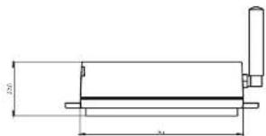
Dimensions
Control Unit
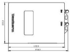
text_image
125.5 172.5 134.4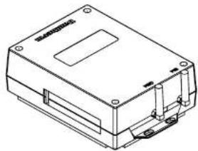
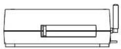
natural_image
Isometric line drawing of a rectangular electronic device with mounting holes and internal components (no text or symbols)Sensor Box
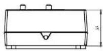
text_image
2.0 3.0

Appendix: Dimensions
Sensor Probe

text_image
DETAIL A SCALE 1 1.8 2 2.5 5.1 DETAIL C SCALE 1 0.8 0.8 A B C 4x 37 4 6.6 90.5 0.5 DETAIL B EN