
D4WVNP - Surveillance Camera Speco Technologies - Free user manual and instructions
Find the device manual for free D4WVNP Speco Technologies in PDF.

| Product Type | 4 Channel HD TVI Digital Video Recorder |
| Model | D4VN (part of D4WVNP series) |
| Video Input | 4 channels, 960H, HD-TVI 1/2/3/4/5/8MP |
| Video Output | VGA and HDMI (Max 1920x1080) |
| Audio Input/Output | 4 local input, 1 local output; G.711 codec |
| Alarm | 4 sensor inputs, 1 alarm output |
| Recording Compression | H.265 / H.264 |
| Recording Resolution & Frame Rate (max) | 8MP@15fps, 5MP@20fps, 2MP@30fps |
| Recording Modes | Smart, Continuous, Motion, Sensor, Schedule, Manual |
| Pre/Post Recording | Pre up to 20 min, Post up to 60 sec |
| Network | 10/100/1000 Mbps, DDNS, NTP, remote access |
| Mobile App | Speco Player (iOS/Android) |
| PC Software | SecureGuard CMS, SpecoTech Multi Client, Web Viewer |
| Storage | Internal HDD (not included), overwrite, recording limit days |
| Power Supply | DC 12V 3A |
| Dimensions (W x H x D) | 11.8 x 2.0 x 9.9 in (300 x 53 x 252 mm) |
| Weight (Gross) | Approximately 4.35 lbs |
| Operating Temperature | 41°F to 104°F (5°C to 40°C) |
| Humidity | 20% ~ 80% (Non-condensing) |
| Key Features | PTZ control via UTC, digital zoom, motion detection, digital deterrent, email alerts |
Frequently Asked Questions - D4WVNP Speco Technologies
User questions about D4WVNP Speco Technologies
0 question about this device. Answer the ones you know or ask your own.
Ask a new question about this device
Download the instructions for your Surveillance Camera in PDF format for free! Find your manual D4WVNP - Speco Technologies and take your electronic device back in hand. On this page are published all the documents necessary for the use of your device. D4WVNP by Speco Technologies.
USER MANUAL D4WVNP Speco Technologies
Model: D4VN, D8VN, D16VN
4, 8 & 16 Channel HD TVI Digital Video Recorder
natural_image
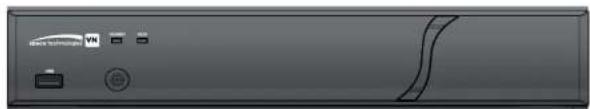
Front view of a gray electronic device panel with buttons and a curved line (no readable text or symbols)Cautions

Explanation of Graphic Symbols

This symbol indicates the presence of important operating and maintenance (servicing) instructions in the literature accompanying the product.

This symbol indicates the presence of "dangerous voltage" within the product's enclosure that may be of sufficient magnitude to constitute a risk of electric shock, property damage, personal injury, or death.
WARNING
These Precautions must be followed for Safety Reasons

Warning
- Do not use if the unit emits smoke.
- Do not disassemble the unit.
- Do not place any heavy or sharp objects on the unit.
- Do not place on uneven surface.
- Do not expose to shock or vibration.
- Do not move the unit when the unit is powered on.
- Do not block, and allow dust to accumulate in the air vents.
- Do not restrict airflow of the unit; doing so can damage the unit.
- Only qualified and experienced personnel should perform installation and servicing.
- Turn off the power of the DVR when connecting Cameras, Audio or Sensor Cables.
- The manufacturer is not responsible for any damage caused by improper use of the product or failure to follow instructions for the product.
- The manufacturer is not responsible for any problems caused by or resulting from the user physically opening the DVR for examination or attempting to repair the unit.
- The manufacturer may not be held liable for any issues with the unit if the warranty seal is removed.
Product Components
Please make sure the following components are included as specified below.
| DVR Unit |  | |
| Remote Control |  | |
| Battery1.5V (AAA x 2EA) | [604H] | |
| Quick Start Guide & Quick User Guide |  |  |
| Mouse |  | |
| Software & Manual CD |  | |
| Adaptor (DC12V 3A) & Power cable (110V) | 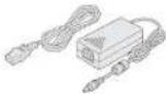 | |
Specifications
| MODEL NAME D4VN D8VN D16VN | |||||
| Video Input Number of Channels 4 8 16 | |||||
| Camera Types 960H, HD-TVI 1/2/3/4/5/8MP | |||||
| Output Main Monitor VGA and HDMI(Max. 1920x1080) | VGA and HDMI(Max. 3840x2160) | ||||
| Sub Monitor CVBS or SPOT (Selectable) N/A | |||||
| Audio Input Local Input 4 | |||||
| Output Local Output1 | |||||
| Audio CodecG.711 | |||||
| Alarm | Sensor In | 4 4 | 4 | ||
| Alarm Output | 1 | ||||
| Serial RS-232C | None | ||||
| RS-4851 | |||||
| Recording | Compression | H.265 / H.264 | |||
| Local Resolution & Frame Rate | 8MP@15fps | 1920x2160 7fps | 1920x2160 7fps | 1920x1080 15fps | |
| 5MP@20fps | 1280x1944 10fps | 1280x1944 10fps | 1280x1944 10fps | ||
| QHD@30fps | 1280x1440 15fps | 1280x1440 15fps | 1280x1440 15fps | ||
| QHD@15fps | 2560x1440 10fps | 2560x1440 10fps | 2560x1440 10fps | ||
| 3MP@18fps | 2048x1535 13fps | 2048x1535 13fps | 2048x1535 13fps | ||
| 2MP@30fps | 1920x1080 15fps | 1920x1080 15fps | 1920x1080 15fps | ||
| Recording Quality Grade | 5 Levels | ||||
| Recording Mode | Smart / Continuous / Motion / Sensor / Schedule /Manual | ||||
| Pre Recording | Max. 20 Minutes | ||||
| Post Recording | Max. 60 Seconds | ||||
| Playback | Search | EZ Search. Date/Time. Event. Log | |||
| Dual Streaming Yes | |||||
| Features Camera | Cerera Control OSD and PTZF Control via UTC | ||||
| Digital Zoom Yes | |||||
| DLS (Day Light Saving) Yes | |||||
| NTP (Network Time Protocol) Yes | |||||
| S.M.A.R.T Yes | |||||
| Internal Beep Yes | |||||
| Multi-Language Yes | |||||
| System Event Notification Health, Restart, Shutdown, Panic Recording, Alarm,Motion, HDD Alert and email | |||||
| Network Access | 3G/4G Mobile Viewer Speco Player (iPad / iPhone / Android)) | ||||
| PC Web Viewer Windows (IE, Edge, Chrome and Firefox) | |||||
| PC Client SecureGuard CMS and SpecoTech Multi-Client Viewer | |||||
| Remote Setup and Upgrade Yes | |||||
| Power Power | Supply Voltage | DC 12V3A | |||
| Temperature | Operation | 41^ F 104^ F (5^ 40^) | |||
| Storage | 14^ F 122^ F (-10^ 50^) | ||||
| Humidity | Operation | 20% ~ 80% (Non-condensing) | |||
| Weight | Unit Weight (Gross weight) | Approximately 4.35 lbs | |||
| Dimension | Unit Dimension (W x H x D) | 11.8" × 2.0" × 9.9" (300 × 53 × 252mm) | |||
Please note that specifications and unit exterior design are subject to change without notification.
Table of Contents
- Main Features 9
- Initial Boot up Process.... 10
2-1. Initial Boot up and Basic Time Setup....10
2-2. Setting Daylight Saving Time 11
2-3. Setting NTP (Network Time Protocol)....12
2-4.EZ Setup....15
- Name, Function and Connection 16
3-1. Front Panel 16
3-2. Connectors ....17
3-3. Remote Control....18
- Setting up the DVR.... 19
4-1. Setup – Main Live Screen....19
4-2. Setup – System Mode....20
4-3. Setup – Record Mode ....24
4-4. Setup – Device Mode 27
4-4-1. Digital Deterrent 28
4-4-2. Keyboard Controller & PTZ Setup 29
4-5. Setup – Display Mode 33
4-6. Setup – Network Mode....34
4-6-1. Network Types....35
4-6-2. DDNS....35
4-6-3. Network Port and Web Port 36
4-6-4. Network Stream....36
4-7. Setup – User Management Mode....38
4-8. Setup – Storage Mode .... 41
1.0 Satun Confia Mode 49
5-3-8. Log List....53
5-4. Playback Mode .... 53
- Export and Back Up....55
6-1. Still Image Backup onto USB Flash Drive....55
6-2. Video Backup onto USB Flash Drive during playback 56
6-3. EZCopy: Video Backup onto USB Flash Drive during playback....57
6-5. Playback of Backup Video....58
6-5-1. AVI Format 58
6-5-2. NSF Format....59
- Network Access Using the Multi-Sites Network Viewer 60
7-1. Overview....60
7-2. PC Requirements....60
7-3. Installation of the Program 61
7-4. Live Window....62
7-4-1.Main User Interface 62
7-4-2. Control Buttons....63
7-5. Search and Playback Window....64
7-5-1.Main User Interface 64
7-5-2. Main Control Panel....65
7-5-3. SMART SEARCH....67
7-6. Setup of SpecoTech Multi Client....69
7-6-1. General 69
7-6-2. Event....70
7-6-3. Record 71
7-6-4. Display 72
7-6-5. Language 72
7-6-6. About....73
7.7 Domota Satun 74
1. Main Features
■ Easy Record, Copy and Setup
■ Easy Search by Thumbnail Preview
■ Easy Copy
■ Digital Deterrent function
■ H.265 & H.264 high quality compression saves HDD space
■ Simultaneous live view/playback while continuing to record/network transfer or backup
■ Remote monitoring/recording/playback/configuration and control via internet
■ 4 Channel Audio Recording
■ Switch between low and high quality stream during simultaneous Continuous + Motion or Continuous + Sensor recording modes for storage optimization
NOTE: Under federal law, The Fourth Amendment to the U.S. Constitution, Title III of the Omnibus Crime Control and Safe Streets Act of 1968, as amended by the Electronic Communications Privacy Act of 1986 (18 U.S.C. § 2510, et seq.), and the Foreign Intelligence Surveillance Act of 1978 (50 U.S.C. 1801, et seq.) permit government agents, acting with the consent of a party to a communication, to engage in warrantless interceptions of telephone communications, as well as oral and electronic communications.
■ Automatic camera detection (Plug & Play)
■ Covert camera operation provides enhanced security and administrator control
■ Dynamically programmable recording priority, motion detection, alarms and scheduling
■ Simple and Easy Graphic User Interface
■ HDMI Output (Up to 3840 x 2160, 16Ch model)
■ Password to secure access
■ Network software supports 10/100/1000Mbps
■ USB 2.0 port for video clip exporting and easy firmware upgrade via USB Flash Drive
■ Exclusive File Format Backup and Player
■ Variety of ways to Dometa process via SecureGuarda CMS, SpaceTech Multi Client Software, Web
2. Initial Boot up Process
2-1. Initial Boot up and Basic Time Setup
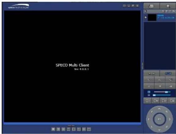
- During the first boot up, the following logo and message will be displayed.

- After the logo, select the language as specified below.

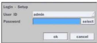
1) User has to set a password before using.
Can not use '1111' when the initial boot up password set.
But user can set '1111' as a password through [Setup > User Management > Password Setup]
2) DVR will not proceed when user put the password '1111'.
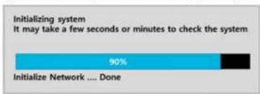
bar
| Category | Value (%) | |---|---| | Initialize the system | 90 | | Initialize Network .... Done | (Not labeled) |2-2. Setting Daylight Saving Time
To enable Daylight Saving feature/NTP synchronization, take the following steps.
- Enter the Setup mode. The default Username is "admin" and enter a password set on the initial boot-up process.

Search
Setup
Display
Snapshot
Super EZ Copy
Enable Manual Record
Instant Playback
Advanced Menu
- Go to Setup > System > Date & Time Setup

- Select 'ok" from the Daylight Saving dropdown menu

2-3. Setting NTP (Network Time Protocol)
- Setup > System > NTP Setup > On > Select
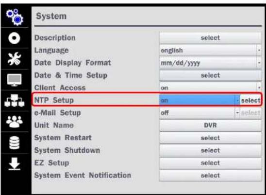
Table 2.3.1. GMT Time Zone
| State Standard Time Daylight-Saving Time | |||
| AL Alabama GMT-6 GMT-5 | |||
| AK Alaska GMT-9 GMT-8 | |||
| AK Alaska (Aleutian Islands) GMT-10 | NA | ||
| AZ Arizona GMT-7 | NA | ||
| AZ Arizona (Navajo) | GMT-7 | GMT-6 | |
| AR Arkansas | GMT-6 | GMT-5 | |
| CA California | GMT-8 | GMT-7 | |
| CO Colorado | GMT-7 | GMT-6 | |
| CT Connecticut | GMT-5 | GMT-4 | |
| DC District of Columbia | GMT-5 | GMT-4 | |
| DE Delaware | GMT-5 | GMT-4 | |
| FL Florida GMT-5 | GMT-4 | ||
| FL Florida (W) | GMT-6 | GMT-5 | |
| GA Georgia | GMT-5 | GMT-4 | |
| HI Hawaii | GMT-10 | NA | |
| ID Idaho (N) | GMT-8 | GMT-7 | |
| ID Idaho (S) | GMT-7 | GMT-6 | |
| IL Illinois GMT-6 | GMT-5 | ||
| IN Indiana | GMT-5 | GMT-4 | |
| IN Indiana (SW / NW) | GMT-6 | GMT-5 | |
| IA Iowa | GMT-6 | GMT-5 | |
| KS Kansas | GMT-6 | GMT-5 | |
| KS Kansas (W) | GMT-7 | GMT-6 | |
| KY Kentucky (E) | GMT-5 | GMT-4 | |
| NV Nevada GMT-8 GMT-7 | |||
| NH New Hampshire GMT-5 GMT-4 | |||
| NJ New Jersey GMT-5 GMT-4 | |||
| NM New Mexico GMT-7 GMT-6 | |||
| NY New York GMT-5 GMT-4 | |||
| NC North Carolina GMT-5 GMT-4 | |||
| ND | North Dakota | GMT-6 GMT-5 | |
| ND | North Dakota (W) | GMT-7 GMT-6 | |
| OH | Ohio | GMT-5 GMT-4 | |
| OK | Oklahoma | GMT-6 GMT-5 | |
| OR | Oregon | GMT-8 GMT-7 | |
| OR Oregon (E) GMT-7 GMT-6 | |||
| PA | Pennsylvania | GMT-5 GMT-4 | |
| RI | Rhode Island | GMT-5 GMT-4 | |
| SC | South Carolina | GMT-5 GMT-4 | |
| SD | South Dakota (E) | GMT-6 GMT-5 | |
| SD | South Dakota (W) GMT-7 GMT-6 | ||
| TN Tennessee (E) GMT-5 GMT-4 | |||
| TN | Tennessee (W) | GMT-6 GMT-5 | |
| TX | Texas | GMT-6 GMT-5 | |
| TX | Texas (W) | GMT-7 GMT-6 | |
| UT | Utah | GMT-7 GMT-6 | |
| VX | Vermont | GMT-5 GMT-4 | |
| VA | Virginia | GMT-5 GMT-4 | |
| WA | Washington GMT-8 | GMT-7 | |
| WV | West Virginia | GMT-5 GMT-4 | |
| WI Wisconsin GMT-6 GMT-5 | |||
2-4. EZ Setup
VN Easy Setup(Click the right button on mouse > Advanced Menu > EZ Setup)
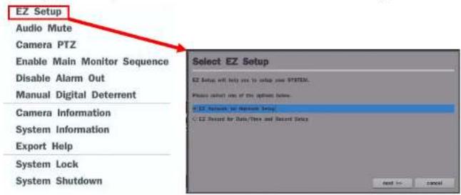
Figure 2.4. EZ Setup Screen
2.4.1. Setup Date/Time and Record configuration


2.4.2. EZ Network (Using an internet connection)
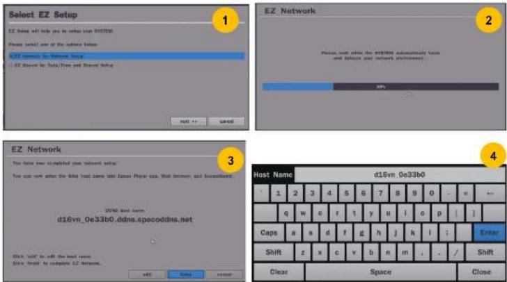
Figure 2.4.2. EZ Network Setup Procedure
① DVR automatically checking the network and configuration by scanning in few seconds.
② DVR will show the DDNS host name when configuration is finished automatically.
③ If you need to edit the host name please select 'edit' button.
④ Everything is OK, then select 'finish'. Host name and status pop-up screen will be showed.
3. Name, Function and Connection
3-1. Front Panel
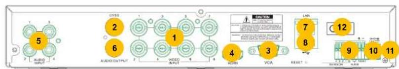
3-2. Connectors

flowchart
graph LR
    A["11"] --> B["2"]
    B --> C["6"]
    C --> D["3"]
    D --> E["1"]
    E --> F["5"]
    F --> G["4"]
    G --> H["3"]
    H --> I["7"]
    I --> J["8"]
    J --> K["9"]
    K --> L["10"]
    L --> M["12"]
    style A fill:#f9f,stroke:#333
    style M fill:#f9f,stroke:#333
D4VN
flowchart
graph LR
    A["5"] --> B["2"]
    B --> C["6"]
    C --> D["1"]
    D --> E["4"]
    E --> F["3"]
    F --> G["VEA"]
    G --> H["7"]
    H --> I["8"]
    I --> J["LAB"]
    J --> K["12"]
    K --> L["9"]
    L --> M["10"]
    M --> N["11"]
    style A fill:#f9f,stroke:#333
    style N fill:#f9f,stroke:#333
D8VN
D16VN
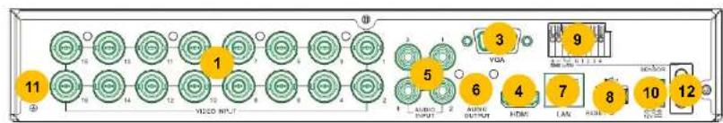
Figure 3.2.1. Rear Panel Connections
① VIDEO IN: Video input port.
3-3. Remote Control
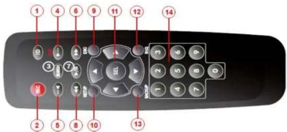
Typical Remote Control
① ID: To set the remote control ID.
② REC: To start and stop manual recording
③ SEARCH: To go to SEARCH menu.
④ F/ADV:
- During playback – To move the playback position 60 seconds forward.
- During Pause – To move the playback position moves 1 frame forward
⑤ F/REW:
- During playback – To move the playback position 60 seconds back.
- During Pause – To move the playback position 1 frame back.
⑥ FF: To fast forward the recording.
⑦ PLAY/PAUSE: To play or to pause the recording in playback mode
⑧ REW: To rewind the recording.
⑨ ESC:
- During setup – To return to the previous menu screen.
- During Playback. To exit playback mode
4. Setting up the DVR
The following sections detail the initial setup of the DVR.

Menu screen will close if user input is not received in 5 minutes.
4-1. Setup - Main Live Screen
To enter the setup menu, right click on the mouse and select setup from the submenu or press the setup button on the remote control.

Figure 4.1.1. Live Screen and Quick Operation Window
4-2. Setup - System Mode
In the Setup menu, select the System tab. Then, the System menu is displayed as pictured below. Navigate through the menu items using the mouse or the remote control and change the value of the menu.
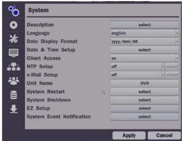
Figure 4.2.1. System Setup Screen
Table 4.2.1. Menu Items in System Setup Screen
Item Description
| Description | Press "select" to view the system information. (Software Version, Storage Size, IP Address, MAC Address and DDNS Status) |
| Model Name | D16VN |

Select Daylight Saving using the mouse or the remote control and select the appropriate daylight saving time zone. The options are:
OFF: Daylight saving is turned off.
ON: Applies the USA daylight saving time.
Select Begin or End using the remote control and press the "ok" button.

Caution
- Do not set the start time to 23:00 for DLS.
- DLS cannot be applied if the date of Begin and End is the same.
Client Access
Enable/Disable remote access through the network.
NTP
NTP (Network Time Protocol) which synchronizes the time of the computer systems over variable-latency data networks.
Setup

Primary SNTP Server: Input the address of the primary NTP time-server.
“NTP server time is faster than the system time.”
In this case, NTP server time is ignored to protect the user data.
User must set the time manually.
System Time: Mon Oct 10 13:46:49 2011
Server Time: Mon Oct 10 13:33:12 2011
DVR ID: DVR
IP ADDRESS: 172.16.2.46"
e-Mail Setup
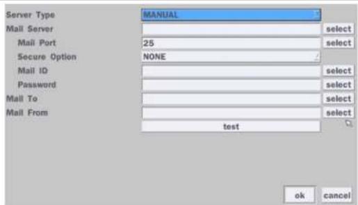
Server Type: Manual, Gmail, Hotmail, AoI or Yahoo
Mail Server: Enter the appropriate mail server information.
Mail Port: Assign Mail Port number.
Secure Option: Select the secure mail server connection method. (SSL or TLS)
Mail ID: Enter the appropriate mail server ID.
Password: Enter the appropriate mail server Password.
Mail To: Enter the appropriate email address to enable sending e-mail reports using a virtual keyboard.
Mail From: To set the email address sent to the destination host.
T-1. T-2.
System Event Notification
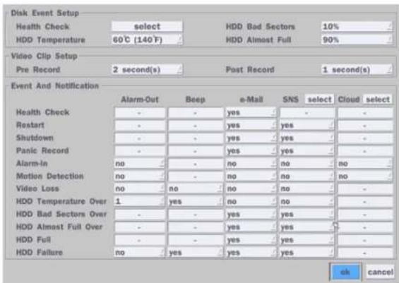
Health Check
(Allows the user to set e-Mail Status periodically): Daily or Weekly or Monthly

Video Clip Setup: Setup the duration of video clip for Pre Record and Post Record.
Event And Notification – Yes or No
(Allows the user to set Event Notification On or Off)
Health Check / Restart / Shutdown / Panic Record
- Enable Email Notification in the event a problem occurs with the VN.
Alarm-In - Enable Email Notification when the camera detects sensor.
Motion Detection Enable Email Notification when the camera detects motion
4-3. Setup - Record Mode
In the Setup menu, select the Record tab. Then, the Record menu is displayed as pictured below. Navigate through the menu items or change the settings using the mouse or the remote control.
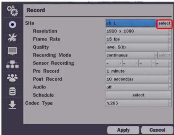
Figure 4.3.1. Record Setup Screen
Table 4.3.1. Menu Items in Record Setup Screen
| Menu Item Description | |
| Ite | Select a channel for applying the following settings using a mouse or a remote control. Select the "select" button beside of channel button to change the values of all channels. |
| Resolution Frame Rate Quality Recording Pre Record Post Record Audio | |
| Resolution | Select 1920x2160, 1280x1944, 2580x1440, 1280x1440, 2048x1535, 1920x1080, 1920x540, 1280x720 and 640x360 using a mouse or a remote control.*Selectable recording resolutions are differ from input camera resolution. |
| Frame Rate | Set the frame rate for the specified channel. The sum of the frame rate values per channel cannot exceed the maximum frame rates for a specific recording resolution. |
| Quality | Select the recording quality for the selected channel. Options are;Level 1 (Low), Level 2, Level 3, Level 4, and Level 5 (High) |
| Recording Mode | Assign the recording mode for the selected channel. Options are: Continuous, Motion, Sensor, Schedule, Disable and Smart Recording (c + m : continuous & motion, c + s : continuous & sensor)When Motion Recording is selected, Continuous + Motion recording option can be used. |
| Sensor Recording | Select the sensor setting for the selected channel. |
| Pre Record | Enable/disable pre-event recording. Pre-event recording time is up to 20 minutes. |
| Post Record | Set the post event recording time duration for the specified channel.(10~60 seconds) |
| Audio | Enable/disable audio recording for the specified channel. It supports only on Ch1~4. |
| Schedule | Set the recording schedule. (Refer to Page 27 Recording Schedule) |
| Codec Type | Select the recording codec (H.264 or H.265)H.265 is over 30% better than H.264 while recording. |
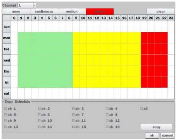
4-3-1. Recording Schedules
To setup a recording schedule, select Schedule in the Record menu. Navigate through the menu items or change the settings using the mouse or the remote control. Select the Channel; select one of the recording settings: None, Continuous or Motion, then highlight the area for the selected setting. To copy a schedule to a different channel, select the channel from the Copy Schedule menu, then click the Copy button.
heatmap
| Channel | none | continuous | motion | clear | | :--- | :--- | :--- | :--- | :--- | | sun | 0 | 1 | 2 | 3 | | mon | 0 | 0 | 0 | 0 | | tue | 0 | 0 | 0 | 0 | | wed | 0 | 0 | 0 | 0 | | thu | 0 | 0 | 0 | 0 | | fri | 0 | 0 | 0 | 0 | | sat | 0 | 0 | 0 | 0 | Copy Schedule □ ch 1 □ ch 2 □ ch 3 □ ch 4 □ all □ ch 5 □ ch 6 □ ch 7 □ ch 8 □ □ ch 9 □ ch 10 □ ch 11 □ ch 12 □ □ ch 13 □ ch 14 □ ch 15 □ ch 16 □ copy ok cancelFigure 4.3.2. Schedule Recording Setup Screen
- none: Disable recording
In the Setup menu, select the Device tab. Then, the device menu is displayed as pictured below. Navigate through the menu items or change the settings using the mouse or the remote control.
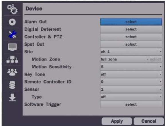
Figure 4.4.1. Device Setup Screen
Table 4.4.1. Menu Items in Device Setup Screen
| Item Description | |
| Alarm Out/ Alarm Duration | Set the sensor, motion, and video loss for triggering alarm relayHDD Error and Video Loss can trigger beeping |
| Alarm-Out 1 | |
| Site | Select specified channel for motion zone setup. |
| Motion Zone | Select either Full Zone or Partial Zone for motion detection. (Refer to #33)Press the right button of mouse to exit from Motion Zone grid screen. |
| Motion Sensitivity | Set the motion sensitivity for the selected channel.Control the motion sensitivity from 1 to 9. (1 : Low, 9 : High) |
| Key Tone | Enable/disable key tone. |
| Remote Controller ID | Set the remote control ID.1. Select ID.2. Input the remote control ID number. (0 is all)3. An icon will indicate on the Live Screen if the remote control ID is synchronized. The options are from 0 to 99 |
| Sensor | Select the type of each sensor.Option is Off, Normal Open or Normal Close. |
| Software Triger | Remote trigger channels. User can set the channels that want to make a sensor recording through remotely with Software record mode. |
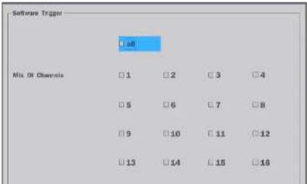
Table 4.4.2. Item for Digital Deterrent Setup Screen
| Item Description | |
| Import From USB | Import up to 8 sound files from USB. |
| Export To USB Export the sound file to USB | |
| Record | Select a channel and set up the date and the duration.And, select the sound file to play. |
| Schedule | Schedule the sound file considering the expected situation. |

Figure 4.4.3. Sensor, Alarm & RS-485 Ports
② Open the PTZ sub menu by selecting the submenu button.
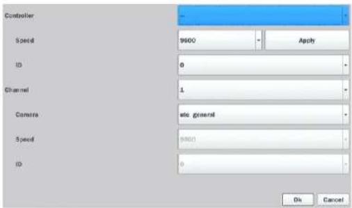
Figure 4.4.4. PTZ Control Setup Screen
Note: Connect PTZ cameras that support RS-485 directly to the RS-485 port. If the camera is controlled through an RS-232C interface, use an RS-232C to RS-485 to RS-232C signal converter.
Use the PTZ setup screen to select the following options for the camera PTZ controller:
- Channel: Channel connected to a PTZ device
- Camera: Protocol Type
Speed: 10200, 14400, 0600, 1800, 2400 (Raul rate)
◆Notice : VN series can use UTC feature.
: UTC(Up To Coax) allows for control of the camera's OSD menu via the coax cable. User does not need extra connection via RS-485 to control the camera's OSD menu
- How to set (Setup > Device > PTZ & Controller > UTC General)
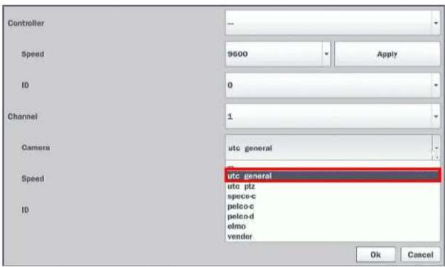
Figure 4.4.6. Setup – UTC Camera Protocol
4-4-3. Spot Out

| periodically. | |
| Sequence Dwell Time | Set the dwell time for the spot channel display.(3-10 sec) |
| Spot Channel | Select a channel for spot monitoring using the mouse or the remote control and press "ok" button. |
4-4-4. Motion Zone Setup
Select Motion Zone using the mouse or the remote control and select either Partial Zone or Full Zone using the mouse control. The default value is Full Zone.
If Full Zone is selected, the motion zone grid screen is not displayed. Only set the level of sensitivity for Motion Sensitivity.
Full Zone: The motion sensor is active on the whole screen.
Partial Zone: The motion sensor is active in the set detection frame.
Select the motion detection position using the mouse or the remote control. Then left click on the mouse or left click and drag the mouse pointer to select or deselect the area. Highlighted area indicates the partial motion detection zone. Press the "ESC" button or right click on the mouse to return to the previous menu.

natural_image
Interior view of a modern exhibition space with glass display cases and ceiling lighting (no visible text or signage)4-5. Setup - Display Mode
In the Setup menu, select the Display tab. Then, the Display menu is displayed as pictured below. Navigate through the menu items or change the settings using the mouse or the remote control. To return to the previous setup menu screen, press the "ESC" button on front panel or select the other menu tab with mouse.
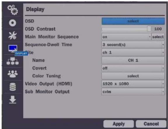
Figure 4.5.1. Display Setup Screen
Table 4.5.1. Menu Items in Display Setup Screen
| Item Description | |
| OSD | Enable/Disable displaying Channel Name/ Video Loss/ Status Bar & Icon/ Camera Type and Record ModeSelect a channel to apply the following settings using the mouse. |
| Name | Set the channel name. Press the mouse button and set the channel name on the virtual keyboard. Press "Enter" key when finished its naming. The name can be made up to 36 characters. |
| Covert | Enable/disable display of the specified video channel in live display. |
| Color Tuning | Control the Brightness, Contrast, Hue and Saturation. |
| Video Output (HDMI) | Select video output resolution(D4VN & D8VN: Max. 1920 X 1080, D16VN: Max. 3840 X 2160) |
| Sub Monitor Output | Select Sub Monitor Video out through BNC port.CVBS or Spot |
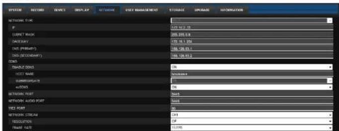
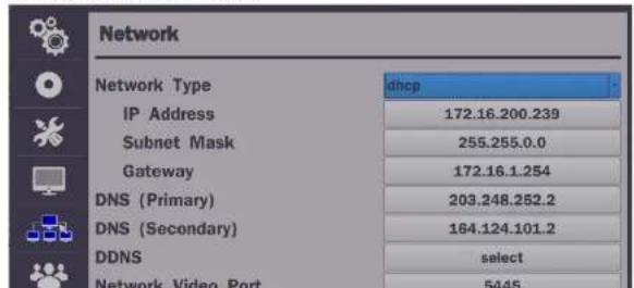
4-6. Setup - Network Mode
Select the Network tab. Then, the network menu is displayed as pictured below. Navigate through the menu items or change the settings using the mouse or the remote control.
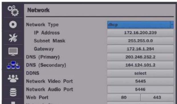
| Gateway | Enter Gateway that is assigned for the DVR. |
| DNS (Primary) | Enter Primary DNS address that is assigned for the DVR |
| DNS (Secondary) | Enter Secondary DNS address that is assigned for the DVR |
| DDNS | Dynamic Domain Name System (DDNS) allows a DNS name to be constantly synchronized with a dynamic IP address. In other words, it allows using a dynamic IP address to be associated with a static domain name so others can connect to it by the static name.Enable/disable using domain name address through DDNS server. |
| Network Video Port | Enter the port number, (Default: 5445) |
| Network Audio Port | Display the network audio port (Network Port + 1). |
| Web Port | Enter the port number for connection using web. (Default: 80) |
| Network Stream Set the value for network streaming. | |
4-6-1. Network Types
4-6-1-1. DHCP
An IP address is automatically assigned by the DHCP server, which automatically assigns the IP address and other parameters to new devices.
4-6-1-2. Static
IP address, Subnet Mask, Gateway, and DNS are manually assigned by the user.
- IP Address: The fixed IP address of the DVR unit.
- Subnet Mask: The subnet mask for the LAN.
• Gateway: The IP address of the Gateway.
• DNS (Primary) The primary address of Domain Name Server
• DNS (Secondary): The secondary address of Domain Name Server

NOTE
Unless DNS is properly set, the DDNS and the e-mail features will not work.

Figure 4.6.2. Network Setup Screen - DDNS
Table 4.6.2. DDNS
| Item Description | |
| Enable DDNS | Enable/disable the Dynamic Domain Name Service. |
| Host Name | This item allows the user to setup a domain name manually, using virtual keyboard displays as shown. |
| Subnet/Update | When manual host name input is done, move the cursor to this item and select ON to submit the settings. |
| ezDDNS | Enable/disable ezDDNS to register the host name automatically. |
4-6-3. Network Port and Web Port
Connecting DVR/DVRs through an IP sharing device, each DVR must be assigned a unique TCP port number for access from outside the LAN. This port number is displayed on Network > Network Port Setup Menu.

NOTE
If you access the DVR only within the same LAN, the TCP port number does not need to be changed.
- D4VN: Up to 60 fps @ 640x360, 320x 240 for 4 channels.
- D8VN: Up to 120 fps @ 640x360, 320x 240 for 8 channels.
- D16VN: Up to 240 fps @ 640x360, 320x240 for 16 channels.
| NET RESOLUTION | FRAME RATE | NET QUALITY | |
| ALL | level 5(h) | ||
| 1 | 640 x 360 | 15 fps | level 5(h) |
| 2 | 640 x 360 | 15 fps | level 5(h) |
| 3 | 640 x 360 | 15 fps | level 5(h) |
| 4 | 640 x 360 | 15 fps | level 5(h) |
| 5 | 640 x 360 | 15 fps | level 5(h) |
| 6 | 640 x 360 | 15 fps | level 5(h) |
| 7 | 640 x 360 | 15 fps | level 5(h) |
| 8 | 640 x 360 | 15 fps | level 5(h) |
| 9 | 640 x 360 | 15 fps | level 5(h) |
| 10 | 640 x 360 | 15 fps | level 5(h) |
| 11 | 640 x 360 | 15 fps | level 5(h) |
| 12 | 640 x 360 | 15 fps | level 5(h) |
| 13 | 640 x 360 | 15 fps | level 5(h) |
| 14 | 640 x 360 | 15 fps | level 5(h) |
| 15 | 640 x 360 | 15 fps | level 5(h) |
| 16 | 640 x 360 | 15 fps | level 5(h) |
Figure 4.6.1 Network Satin Screen Network Stream
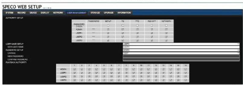
4-7. Setup - User Management Mode
In the Setup menu, select the User Management tab. Then, the User Management menu is displayed as pictured below. Navigate through the menu items or change the settings using the mouse or the remote control.
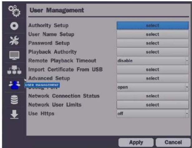
Figure 4.7.1. User Management Setup Screen
Table 4.7.1. Menu Items in User Management Setup Screen
| Item Description | |
| Authority | Only the Admin will have access to the menu. |
| Setup | Password Check: Select the Checkbox to enable the functions or leave the Checkbox |
| Password | Setup | PB | PTZ | Race Off | Network | |
| Password Check | M | H | E | R | E | |
| ADMIN | M | E | X | R | E | |
| USER1 | M | X | X | R | E | |
| USER2 | M | E | X | R | E | |
| USER3 | M | H | X | R | E | |
| USER4 | X | E | X | R | E | |
| USER5 | M | E | X | R | E | |
| USER6 | M | X | X | R | E | |
| USER7 | M | H | X | R | E | |
| USER8 | M | H | E | R | E | |
| USER9 | M | H | E | R | E |
ADMIN, USER1, USER2, USER3, USER4, USER5, USER6, USER7, USER8, USER9:
Selected Checkbox: The user can access the function.
Blank Checkbox: The user cannot access the function.
User Name Setup
Change the name of USER1, USER2, USER3, USER4, USER5, USER6, USER7, USER8, and USER9. Click "select" and change the user name on the virtual keyboard.
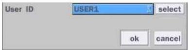
Password Setup
Options are ADMIN, USER1, USER2, USER3, USER4, USER5, USER6, USER7, USER8, and USER9:

Select User Password using the mouse or the remote control. Select "User ID" and enter the current password. And enter a new password and enter the same password again to confirm and select "ok". Then the message "Password Changed" is displayed.
“……”
| Remote Playback Timeout | Disconnect the remote playback after the specific time (Disable, 5min, 10min, 15min, 30min, 60min. |
| Import Certificate From USB | Upload https certificate through USB |
| Advanced Setup | Send IP address and ports information to the control center |
| Debug Port | Open or Close the ports for remote checking |
| Network Connection Status | Shows the current network connection status (User, IP Address, Date/Time). And do disconnect the user's network connection to click 'disconnect' button. |
Network User User can select network access user number (4 users of 12 users).
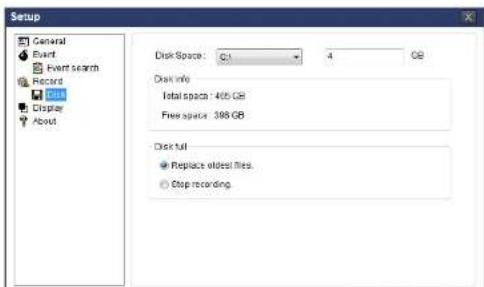
4-8. Setup - Storage Mode
In the Setup menu, select the Storage tab. Then, the Storage menu is displayed as pictured below. Navigate through the menu items or change the settings using the mouse or the remote control.

Figure 4.8.1. Storage Setup Screen
Table 4.8.1. Menu Items in Storage Setup Screen
| Item Description | |
| Overwrite | When enabled, the DVR will continue recording and overwrite the oldest existing recorded data once the hard drive is full. When disabled, recording will stop once the hard drive is full. |
Disk Format User will have an option for formatting the Hard Drive.
| Disk Info | Hard drive information.Displays the following information: | |||
| HDD Size : 1740 GB (Free : 722 GB)HDD Last Time : 05/25/2016 17:22:00 | ||||
| Model Name | Temperature | Health(Good/Normal/Bad) | ||
| HDD 1 | WDC WD20PURX-64P6ZY0 | 39 °C (102 °F) | Good | |
| HDD 2 | ||||
| Recording Limit | Enable recording limit: The amount of data recorded in HDD will be limited to themost recent number of days as set by “Recording Limit Days”.Disable recording limit: When Overwrite is on, DVR will continue to record wheHDD is full and overwrite older data. When Overwrite is off, DVR will stop recordingwhen the HDD is full. | |||
| Recording LimitDays | Set the recording limit days. (1- 90 days)If the Recording Limit Days are set to 1, the data will be overwritten after 24 hours. | |||
4-9. Setup - Config Mode
In the Setup menu, select the Config tab. Then, the configuration menu is displayed as pictured below. Navigate through the menu items or change the settings using the mouse or the remote control.

Table 4.9.1. Configuration Setup
| Item Description | |
| Export To USB | User can save the current configuration (Setting values) of the DVR to the USB flash drive. Plug in the USB flash on the front panel and press the button to start the saving process. |
| Import From USB | User can upload the configuration of the DVR to another DVR using the USB Flash drive. Plug in the USB flash drive on the front panel and press the button to start the loading process. |
| Load Default | Press the button to reset the system to the default settings.The following settings such as Language, DVR ID, Security User Authentication, Security User P/W, Date Format, DLS settings, Network settings, HDD overwrite, Limit recording, HDD serial number, and HDD ERROR time will not be included. |
| Load Factory Default | Press the button to reset the system to the factory default settings. |
| Software Upgrade | Upgrade software to the latest version.After connecting USB flash drive to USB port on the DVR, click SEARCH.It will automatically find the upgrade file. |
4-9-1. Software Upgrade
- In the USB flash drive root directory, create a new folder named "upgrade"
- Create sub-folder for each model under "upgrade" folder and copy each software file to their folder.
- "d4vn" for D4VN: "main_d4vn_speco_.*.*_202****"
- "d8vn" for D8VN: "main_d8vn_speco_.*.*._202****"
- "d16vn" for D16VN: "main_d16vn_speco_.*.*_202****"

Figure 4.9.2

Figure 4.9.3
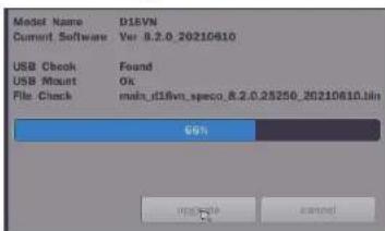
Figure 4.9.4
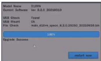
Figure 4.9.5

NOTICE
If selecting "Restart Now" when the USB flash drive is plugged, the following message will pop up with beep sound.

5. Live, Search and Playback
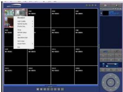
5-1. Live View
In the Live screen, video inputs from the cameras are displayed as they are configured in the Display Setup screen. When the mouse is right clicked, and the quick operation window will be displayed as below.
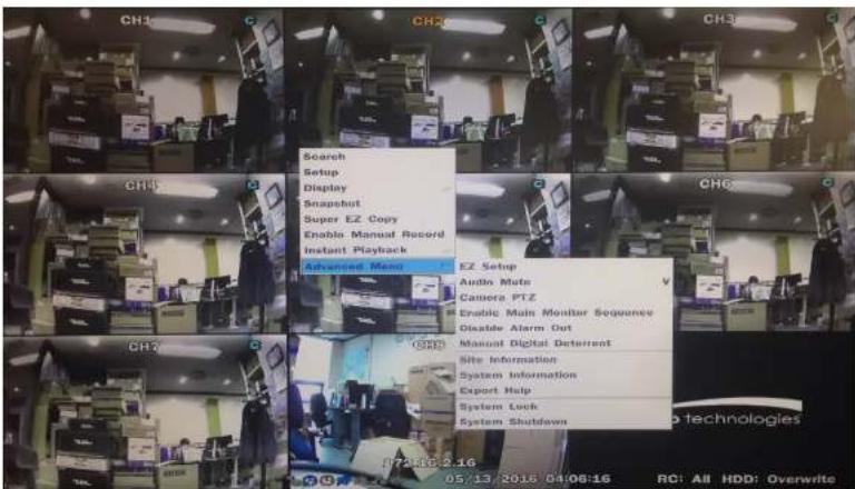
Figure 5.1.1. Live Screen and Quick Operation Window
On the bottom of the screen, various On-Screen Display (OSD) symbols, which indicate the status of the DVR, are described in Table 5.1.1.
Table 5.1.1. Status Indicator Icons in Live Viewing Screen
| Icon Description | |
 | Indicates the DVR is locked. Note) to unlock, right click on the live view screen and select on Unlock. |
| Audio mute. Audio channel output can be selected from the quick operation menu | |
 | Indicates that alarm is set. |
 | Indicates that alarm output is activated. |
 | Event indicator. When there is an event (motion recording, video loss, HDD fail, S.M.A.R.T), this icon will be highlighted. |
 | Indicates that a network client is connected to the DVR. |
 | Indicates that sequencing mode is enabled. |
2009/04/14 17:23:40
Displays the current date and time.
RC: ALL Remote control ID display. If a remote ID is not set, the message "ALL" is displayed.

15%
When Overwrite is not enabled, this displays the percent of the hard disk usage from 0-99%.
When Overwrite is enabled, the Bar will indicate with Overwrite


Continuous recording in progress.
Manual recording in progress. To set the Manual recording mode, press the Record button on the front panel.
Motion alarm recording in progress
| going through the search mode. | |
| Enable Manual Record | Manual Record button. Click this button to enable manual recording. Also known as Panic Record. |
| Instant Playback | Instant playback on each channel for 10 / 20 / 30 / 60 seconds |
Advanced Menu
| EZ Setup Select this option to start EZ Setup Wizard | |
| Audio Mute Select audio output on or off | |
| Camera PTZ Select this option and the PTZ user interface will appear. (Refer to 5-1-1, PTZ Control on page 49) | |
| Enabel Main Monitor Sequence | Select this option to enable/disable sequence function. |
Disable Alarm Out Click this button to enable/disable Alarm outputs
| Manual | Window where users can manually trigger the digital deterrent audio |
| Digital Deterrent | "Right now it just says "use". |
Camera information Press the button to view the camera signal information of a selected channel.
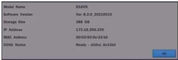
System Information Press the button to view the system information.
| Model Name | D10VN |
| Software Version | Ver 8.2.0 20210610 |
| Storage Size | 388 GB |
| Network Type | Dhcp |
5-1-1. PTZ Control
Table 5.1.3. Menu Items in PTZ Control Window
| Image Item Description | ||
| INITIALIZE | Initialize the PTZ settings of the selected camera | |
| PAN/TILT | Select PAN/TILT using the ▲▼◀ and ▶button, then press SEL. Adjust the tilt (UP/DOWN)/pan (LEFT/RIGHT) position using the ▲▼◀and ▶buttons. | |
| ZOOM/FOCUS | Select ZOM/FOCUS using the▲▼◀ and ▶buttons, then press SEL. Adjust the zoom (UP/DOWN)/ focus (LEFT/RIGHT)position using the ▲▼◀ and ▶ buttons. | |
| OSD | Select OSD to enter the menu. Control keys are Right, Left, UP, Down, Select, Far (REW KEY), and Near (FF KEY). Press the ESC button to return to the previous menu. Press the PTZ button to close the OSD menu. | |
| AUTOSCAN | Press the right key(▶) to start auto scan. Press the left key (◀) to stop auto scan. | |
| PRESET | Select PRESET, then press the left key(◀). A number input window will appear. Set the number (3digits) using the number key, then press the SEL to confirm the preset number for the current position. Press the right key (▶) and enter the number (3digits) to go to the preset position. | |
| TOUR | Select TOU and press the right (▶) key. A number | |
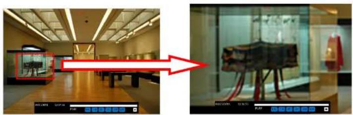
5-2. Digital Zoom in Live and Playback Screen
VN series supports Digital Zoom feature during live and playback mode.
- Double click the target channel.

- Click the left button of the mouse and drag to make rectangular shape.
5-3. Search Screen
To enter the search screen menu, select Search menu on the screen using the mouse or press Search icon on live screen.

There are 7 options in the Search Menu, they are: EZSearch, Time Line (Calendar), Event, Go To First Time, Go To Last Time, Go To Specific Time, Archive list, and Log list on the screen.
5-3-1. EZSearch
The EZSearch window is used to find stored video with ease using the thumb nail playback screen.
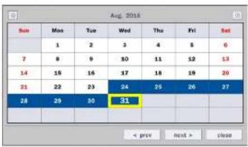
Figure 5.3.2. Calendar Screen
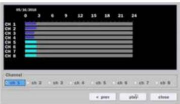
Figure 5.3.3. Channel Selection Screen

Step1. 24 Hourly Thumbnail Screen
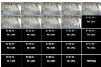
Step2. Every 2 minutes and 30 seconds

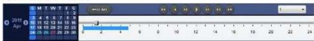
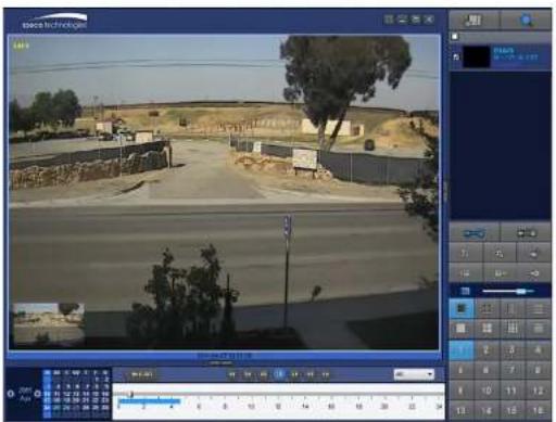
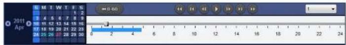
5-3-2. Time Line Search
The Calendar Search window is used to find the stored video by using the time line bar.
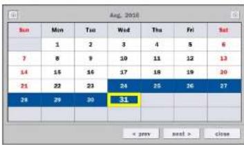
Figure 5.3.5. Calendar Screen
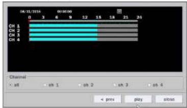
Figure 5.3.6. Time-Line Search Screen
When the Timeline menu is selected, the user can see a calendar, which displays recorded dates with highlights. Select a specific date and time. Click and drag the red time indicator bar to the desired hour. User can select a specific minutes using a button in the above red box. Press the "play" button after selecting the specific time. Press the "prev" to return to the Search window.
5-3-3. Event Search
The Event Search window is used to find stored video.

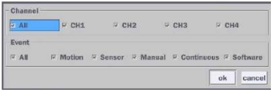
Figure 5.3.8. Event Search Screen
5-3-4. Go To First Time
You can access the oldest recorded data on the DVR hard drive by selecting Go To First Time on the Search window. Press the "prev" to return to the Search window.
5-3-5. Go To Last Time
You can access the latest recorded data on the DVR hard drive by selecting Go To Last Time on the Search window. Press the "prev" to return to the Search window.
5-3-6. Go To Specific Time
User can search for video data from a specific instance by setting the date and time in the GO TO SPECIFIC TIME menu. Use the mouse or the remote control to change the date and time value and press the PLAY button after setting. If there is no video data in the set date and time, No Data Exist message displays.
5-3-7. Archive List
The ARCHIVE Search window is used to find previously stored video or images.
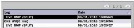
5-3-8. Log List
You can access the LOG list search screen by selecting LOG on the SEARCH window.
![Log Date NTP : Keep(earlier than system time) 08/31/2016 04:00:00 System Start : [25] Software Upgrade 08/31/2016 13:58:33 Video In : CH1 08/31/2016 13:58:34 Video In : CH2 08/31/2016 13:58:34 Video In : CH3 08/31/2016 13:58:34 Video In : CH4 08/31/2016 13:58:34 NTP : Keep(earlier than system time) 08/31/2016 13:59:00 7 log(s) found backup < prev next > close](/content/2026/06/1216674/images/075b3e1338a25e40635ac9e15af665213d3462ba099474be7a1840306a682158.jpg)
Figure 5.3.10. Log List Screen
When the Log menu is selected, the user can see a calendar, which has a log data. Select a specific date and press NEXT button, and then the log data will be displayed. Press the SAVE button to save the data and then the data is saved as a text file format.
5-4. Playback Mode
During playback of a recorded event, the mode changes from SEARCH to PLAY. While in PLAY mode, you may return to the SEARCH screen by pressing the X button on the status bar.

natural_image
Interior view of a modern exhibition hall with ceiling lights and display cases (no visible text or signage)


Single Channel backward playback speed 1x, 2x, 4x, 8x, 16x, 32x, 64x
Jump/Step backward. The playback position moves 60 seconds backward.
Press to play or pause recorded video.
Jump/Step forward. Playback position moves 60 seconds forward.
• 2x, 4x, 8x, 16x, 32x for D4VN
- 2x, 4x, 8x, 16x for D8VN
• 2x, 4x, 8x for D16VN
Single Channel forward playback speed 1x, 2x, 4x, 8x, 16x, 32x, 64x
Slow Mode play. Forward playback speed x1/4, x1/2
Press to back up the video. User can select archive file formats (Still image, NSF, AVI and EXE).
EZCopy button. User can copy video data as NSF, AVI and EXE format.
Return to the previous menu screen, search window, or exit from the Menu.
6. Export and Back Up
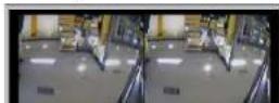
6-1. Still Image Backup onto USB Flash Drive
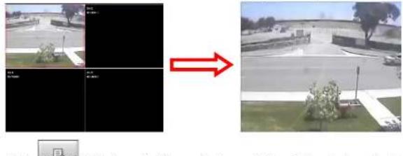
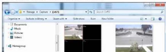
Still images can be captured and archived onto a USB flash drive or an USB external hard drive in live mode or while playing back recorded video.
- Select a specific channel, which wants to back up on live screen.
- When you press "Snapshot" button on Quick operation window, the media selection window screen will display.
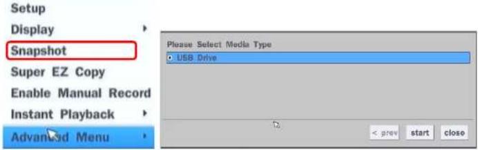
- Once you press "start" button, the system will capture a still image and archive onto a USB flash drive.

NOTICE
USB Flash Drive must be in FAT32 file format.
6-2. Video Backup onto USB Flash Drive during playback
Video can be captured and archived onto the USB flash drive or a hard drive while playing back the
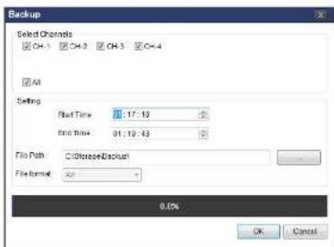
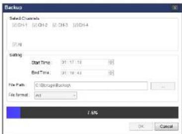
recorded video. In playback mode, press the "Export" button to launch the backup function.
- When you press "Export" button on the selected channel or all channels, the DVR will ask whether to archive a Still Image, NSF, AVI or EXE and select the proper media type.
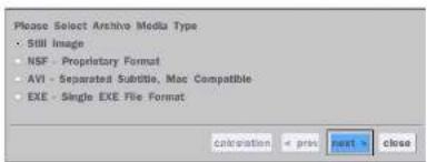

- Select USB Drive (Flash Drive) to back up less than an hour. Select USB HDD (Large Backup) to back up from 1 hour to 24 hours. (Only for NSF type)
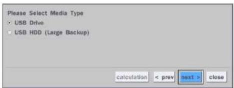
- Once you select the channel and duration, the system will start to archive the data to the USB drive.
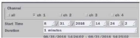
- The following shows the image to complete the backup. Select lose to return to the previous screen.

6-3. EZCopy: Video Backup onto USB Flash Drive during playback
Using EZCopy feature, Video can be easily archived onto the USB flash drive or a hard drive.
In playback mode, press the "Copy" button to launch the backup function.
- Press "EZCopy" button on the selected channel or all channels.

- Then, EZCopy START time will display.

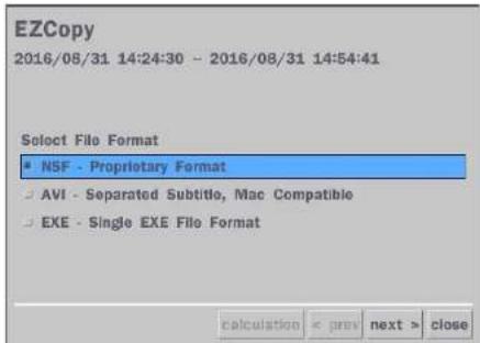
- After backup format is selected, also select media type and channel(s) to archive the data to the media.
6-5. Playback of Backup Video
6-5-1. AVI Format
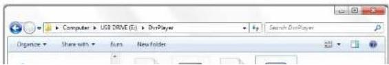
AVI format: AVI format video can be played back by Window Media Player™ or other media player that is compatible with AVI format video.
- Please install the Decoder Filter that the DVR copies "DvrPlayer" folder on USB flash drive with the video. Decoder Filter is exported to the "/DvrPlayer" folder of the USB drive.

Timestamp On AVI. The subtitle is embedded to the video clip file.
The subtitle is embedded to the AVI file. To display a subtitle, user should install a special filter called "Decoder Filter".
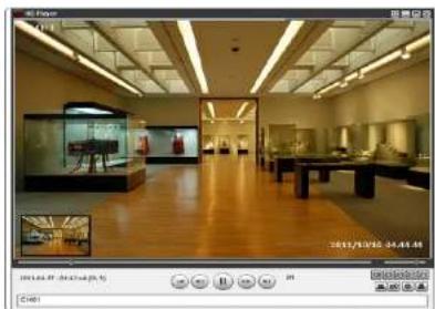
6-5-2. NSF Format

NSF format: NSF format video can be played back using the HDplayer that the DVR copies to
"DvrPlayer" folder on USB flash drive with video. Use the mouse scroll to use digital zoom in and out feature.
natural_image
Interior view of a museum gallery with wooden flooring, display cases, and glass cases (no visible text or signage)7. Network Access Using the Multi-Sites Network Viewer
7-1. Overview
The SpecoTech Multi Client is a multiple site monitoring client software with; video, audio, and alarm signals from the DVRs over the network. The SpecoTech Multi Client does not limit the number of DVR units to register.
The program displays up to 16 DVRs and supports dual monitors.
On the program, user may control PTZ cameras on the DVRs. By attaching a microphone and speaker system to devices on site, the user may make bi-directional audio communication over the network.
7-2. PC Requirements
Minimum PC Requirements
| CPU Intel Core | 3 |
| 1.8Ghz | |
| Memory 2GB DDR2 | |
| VGA 512MB | |
| Resolution 1280x720 | |
| Disk Space 1GB | |
| OS Windows 7, 8, 10 | |
| Network 10/100Base T | |
| Others | Direct X 9.0c or Higher |
Recommended PC Requirements
| CPU Intel Core | 5 |
| 2Ghz or higher. | |
| Memory 4GB DDR3 or higher. | |
| VGA 512MB or higher. | |
| Resolution 1920x1080 | |
7-3. Installation of the Program
- Insert the provided CD in the CD drive and double-click "SpecoTech Multi Client (XXXX).exe"

- Select a destination folder and click "Next".
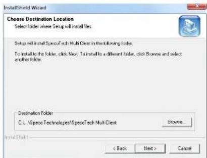
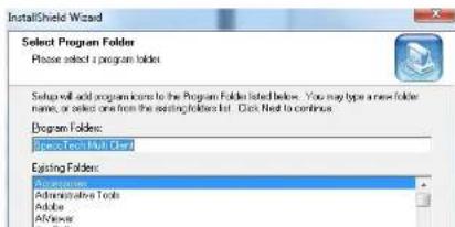
- Select the program folder and click "Next".
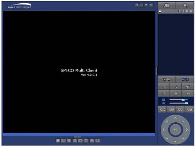
7-4. Live Window
When installation is completed, double click the "SpecoTech Multi Client" icon on your desktop to start the program.
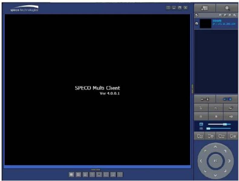
7-4-1. Main User Interface
7-4-2. Control Buttons
| Button Description | |
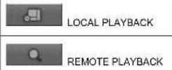
 LOCAL PLAYBACK LOCAL PLAYBACK | Click this icon to run a playback window to search and play videos that are recorded in the local PC. |
 REMOTE PLAYBACK REMOTE PLAYBACK | Click this icon to run a playback window to search and play videos that are recorded in the remote DVR. |
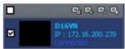
 [IMAGE]SITE MANAGEMENT [IMAGE]SITE MANAGEMENT | THUMBNAIL REFRESH: Click this icon to refresh and renew thumbnail image of the connected sites.SITE ADDITION: Click this icon to open 'Site Addition' window.SITE DELETE: Click this icon to delete site from the index window, after disconnect a site.NET FINDER: Select the site from the index window and click this icon to modify the information of specific site. |
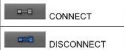
 CONNECT CONNECT | Click this icon to connect the selected site/sites. |
 DISCONNECT DISCONNECT | Click this icon to disconnect the selected site/sites. |
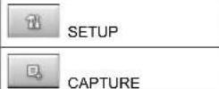
 SETUP SETUP | Click this icon to setup configuration of SpecoTech Multi Client. |
 CAPTURE CAPTURE | Click this icon to capture a still image. |
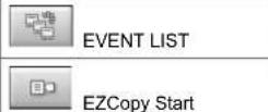
 EVENT LIST EVENT LIST | Opens list of events logged by the SpecoTech Multi Client. |
 PAUSE PAUSE | Click this icon to play/pause live video. |
 ALARM ON ALARM ON | Click this icon to turn on/off alarm outputs. |
7-5. Search and Playback Window
7-5-1. Main User Interface
You can access to search window by clicking the search icon (Local Playback / Remote Playback) on the upper right of the Live Window.
7-5-2. Main Control Panel
| Button Description | ||
 | Click this icon to run a playback window to search and play videos that are recorded in the local PC. | |
| Click this icon to run a playback window to search and play videos that are recorded in the remote DVR. | ||
 | Display the site information and the connection status. | |
 | Click this icon to connect the selected site/sites. | |
| Click this icon to disconnect the selected site/sites. | ||
 | Click this icon to setup configuration of SpecoTech Multi Client. | |
| Click this icon to capture a still image. | ||
 | Opens list of events logged by the SpecoTech Multi Client. | |
| Click this icon to set the beginning time for backup of the recorde video in AVI format. | ||
 | Click this icon to set the ending time for backup of the recorded video in AVI format. | |
| Click this icon to backup the recorded video in AVI format. | ||
 | Use the volume control bar to set the audio level. | |
 | To change a timeline scale from 24 hours to 60 minutes.The timeline shows recorded data in color on the bar. You can adjustthe timeline scale and move it to the time you wish to playback. Thenclick the play icon to display the recorded video. | |
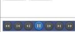
| Playback buttons. | ||
 | EZSEARCH: Thumbnail search over the network.- Shows 24 thumbnail images, one for each hour from 00:00 to 23:00.- Each hour is further broken up 24 segments; each is 150sec.- Then select the tile to play* Click the "PREVIOUS" button to go the previous step. | |
 | Digital Zoom Window in Live and Playback. (Only available in SingleChannel Viewing) | |
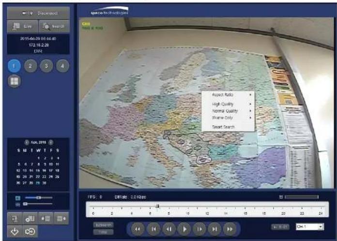
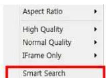
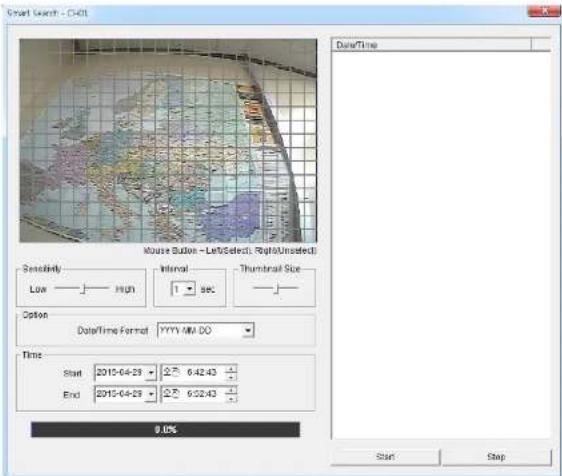
7-5-3. SMART SEARCH
1) User can search with selected area
2) Click right mouse button when playback

7-6. Setup of SpecoTech Multi Client
Click the setup icon to setup the configuration of SpecoTech Multi Client software. The SETUP window is displayed as below.
7-6-1. General
Security Option: Set a password for security options. Select security options and set a password.
Then when you access any of selected functions, you need to enter the password.
You can also set the save path for capturing and backup.
Save Path: Specify the location to save captured still image for Capture and Backup data.
Miscellaneous
Automatic Reconnection: If enabled, the software will automatically try to reconnect to the last successful IP address. But, when CLIENT ACCESS is OFF on the DVR, the software will not try to reconnect even if it is enabled.
Always On Top: If enabled, the software display will be continuously on the top of other windows.
Time Format: Change the way the Client software displays the time.

7-6-2. Event
Event log can be archived and searched.
Event Log: Specify the location to save event logs and select event to archive.

Event Search: Event log can be searched from the selected time.

7-6-3. Record
Record Setup: You can set the recording conditions as the following; Always, Event, or Auto record. And you can also select target DVR/DVRs and channel/channels. When you set the recording condition to event, you can set event for motion or alarm with duration.

Record Local Storage Setup: You can select the local disk to record and the amount of disk space you want to allow the program to use for recording. You can also select the option to overwrite data or stop recording when the maximum amount of disk space is full.

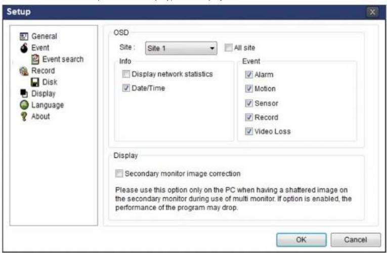
7-6-4. Display
You can select the OSD (On Screen Display) to be displayed.
7-6-5. Language
English, French and Spanish is selectable.

7-6-6. About
"About" provides network client version information.

7-7. Remote Setup
The menu settings for the DVR unit can be set over network.
Put the cursor of the mouse on the channel, which is connected to the site and right click on the mouse to open the submenu. Then the following window is displayed as below. Select the REMOTE SETUP.

Then the setup window is displayed. The specified menu screen is displayed on the upper left of the screen.
Enter the password of the DVR when prompted. (NOTE: The password is same with DVR setup password.)
Setting is the same as with the DVR menu setting. Refer to the corresponding pages for details on the setting items.
7-7-1. System
Select System to set system and time settings.

• DATE DISPLAY FORMAT: Select the date display format.
- CLIENT ACCESS: Enable/Disable remote access through network client software.
• NTP SETUP: Sets whether to synchronize the time using NTP server or not.
Primary CMTD Server: Input the NTD primary server address
- SEND MAIL TEST: Examine the function with registered information.
- USER NAME: Name the DVR
- SYSTEM RESTART
- SYSTEM EVENT NOTIFICATION
Allows the user to set EVENT NOFICIATION ON or OFF
- HEALTH CHECK
(Allows the user to set MAIL STATUS periodically): DAILY or WEELY or MONTHLY - HDD TEMPERATURE
- HDD BAD SECTOR
- HDD ALMOST FULL
- VIDEO CLIP SETUP: Setting the duration for pre and post recording.
- EVENTS AND NOTIFICATION
- HEALTH CHECK / RESTART / SHUTDOWN / PANIC RECORD
Enable Email Notification in the event a problem occurs with the VN.
- ALARM-IN : Enable Email Notification when the camera detects sensor
- MOTION DETECTION : Enable Email Notification when the camera detects motion
○ VIDEO LOSS: Enable Email, Beep and Alarm output Notification when the camera signal is lost. -
HDD TEMPERATURE : Enable Email Beep and Alarm output Notification when the HDD reaches the maximum temperature
-
HDD BAD SECTOR: Enable Email Notification when the HDD has bad sectors.
- HDD ALMOST FULL: Enable Email Notification when the HDD is almost full.
- HDD FULL: Enable Email Notification when the HDD is full.
- HDD FAILURE: Enable Email, Beep and Alarm output Notification when the HDD fails.
7-7-2. Record
Select RECORD tab to set the recording conditions.
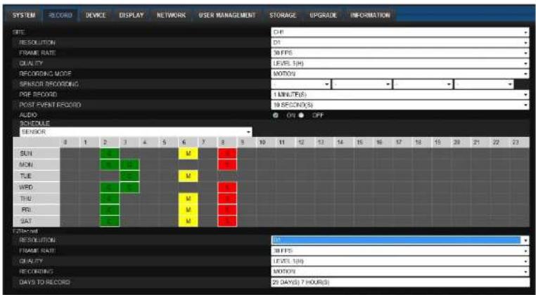
These settings apply to the specified channel only.
- Recording Setup
o RESOLUTION: Sets the resolution for the recordings. The value applies to an individual channel.
o FRAME RATE: Sets the recording rate.
o QUALITY: Sets the image quality in 5 levels.
o RECORDING: Sets the recording mode.
- RECORDING MODE: CONTINUOUS, SCHEDULE, MOTION, SENSOR
o PRE RECORD: Sets whether to perform or not prerecording.
- POST EVENT RECORD: Sets the duration of the event recording
7-7-3. Device
Select Device to set Spot Out, Enable/Disable CVBS Out, motion zone.

RELOAD APPLY
• ALARM OUT: Set the alarm out duration.
- DIGITAL DETERRENT: Set the schedule of digital deterrent function and upload the sound file to DVR.
• CONTROLLER: Set the controller baud rate and ID.
• PTZ: Set the PTZ baud rate, protocol, and ID.
- SPOT: Enable/Disable the SPOT OUT and SEQUENCE.
NOTION: Cause the motion detection was and the velocity.
7-7-4. Display
Select the DISPLAY tab to set the DISPLAY conditions.

These settings apply to all channels.
- OSD: Sets whether to display or not, the date and time as well as channel number on the screen.
- OSD CONTRAST: Adjust the character contrast on the screen.
- MAIN MONITOR SEQUENCE: Setting for automatically switching the displayed video.
SEQUENCE DWELL TIME: Sets the interval for automatically switching the screens. - SITE: Name, Covert, Brightness, Contrast, Hue, Saturation These settings apply to the specified channel only.
7-7-5. Network
7-7-6. User Management
Select the USER MANAGEMENT tab to set the DISPLAY conditions.
RELOAD APPLY
7-7-7. Storage
Select Storage to configure continued recording settings by overwriting the hard disk and the storage period for the recording data.

RELOAD APPLY
• OVERWRITE: Continues recording by writing over previous recordings when HDD is full.
- DISK INFO: Shows the information of HDD installed in DVR
- RECORDING LIMIT: Sets whether to limit or not, the recording data storage period.
7-8. Operation
7-8-1. Addition, Delete, and Modify of DVR Sites
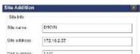
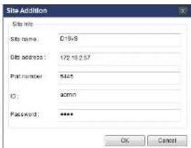
7-8-1-1. Addition of Sites
- Click SITE ADDITION button. And then the following window will be displayed as below.


- Site Name: Input a name that properly describes a site.
- IP Address: Input IP address (Public IP address of a router that DVR is connected.) or Domain name
- Port Number: Default Port Number is "5445".
- ID: Input ID of DVR. Default ID is "admin".
-
Password: Input network password of DVR that is same with DVR setup password.
-
Click OK button. And then the registered site is added on the directory window.
7042 Deleting a Site

- Click NET FINDER button. And then the following window will be displayed as below.

- Click Modify button. And then the modified information is displayed as below.

7-8-2. Connect and Disconnect
7-8-2-1. Connect
- Select site/sites to connect from the directory window.

- Click CONNECT button, and then site/sites displays/display as connected.
7-8-2-2. Disconnect
- Select site/sites to disconnect from the directory window.

7-8-3. Still-image Capture During Live
- Double-click a channel to capture from the display screen. (Otherwise all channels will be captured.).
- Click CAPTURE button. And then a Capture window will be displayed as below.

- Set Save Path, File Name, and File Format. And then click OK button.
- Still image is saved as set in Capture window.
7-8-4. Recording Video on Local PC During Live
- Click SETUP button. And then a setup window will be displayed as below.
- Select Record and set the values.

- Select Disk and set the values.
7-8-5. Local Playback and Remote Playback
7-8-5-1. Playback of Recorded Video on a Local PC
- Click LOCAL PLAYBACK. And then Playback Window will be displayed over the Live
Window.

-
Select site/sites to connect from the directory window.
-
Click CONNECT button. And then Green bar displays on Search calendar and timeline scale window.
- Move the marker on the timeline scale to where there is video data and press the PLAY button.
- Video data that is recorded on local PC will be play-backed.
7-8-5-2. Playback of Recorded Video on Remote DVR
- Click REMOTE PLAYBACK. And then Playback Window will be displayed.
-
Select the site to connect from the directory window.
-
Click CONNECT. And then Green bar displays on Search calendar and timeline scale.

- Move the marker on the timeline scale to where there is video data and press the PLAY button.
7-8-6. AVI Backup during Playback
You can back up the recorded videos in AVI format during playback.
- Double-click the target channel to backup.
- Select the beginning time by using the search calendar and timeline scale bar.
- Click EZCOPY START button on the timeline scale to select the beginning point of the backup.

- You can also set the beginning time and ending time on this window. After selecting a channel for backup, click the OK button. The backup will begin.
- AVI video data is recorded as selected in AVI Backup window. AVI format video can be played back by using Window Media Player™ or other media player that is compatible with AVI format video.
8. Network Access Using the Web-Browser Viewer
The DVR provides a live remote monitoring feature by web-browser viewer. (NOTE: Web-Browser is only available for Internet Explorer)
- Check the IP address of the DVR from SETUP>SYSTEM>DESCRIPTION>IP ADDRESS or
- Input the IP address or Domain name address that you pre-registered.

- Click this bar. Then the dialog box is displayed.

- Click "Install" to download and install the ActiveX control.

- The Web Browser Viewer will be displayed as below after the ActiveX installation

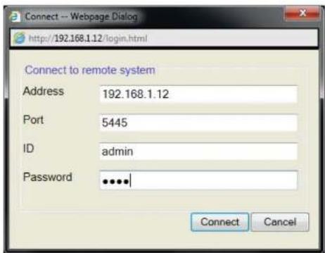
- Site Name: Input a name that properly describes a site.
-
IP Address: Input IP address (Public IP address of a router that DVR is connected.) or Domain name
• Port Number: Default Port Number is "5445".
• ID: Input ID of DVR. Default ID is "admin". -
Password: Input network password of DVR that is same with DVR setup password.
- Then the cameras connected to the DVR are displayed on the screen.
- Use mouse scroll to digitally zoom in and out from a single channel display.
9. Network Access Using the Smart Phone Viewer

Notice
Data Usage applied without Wi-Fi connection. Please check with your Phone Carrier.
9-1. App Viewer for iPhone
- Enter the Apple App Store.


- Search "Speco Player" in the App Store.

Notice
SPECO Player is for the VN, VX2, VX, VT, HT, HS, ZS, NS, DS, RS and HD series DVRs. SPECO VIEWER is not compatible with the T Series DVR's (TH, TN or TL) or the PC Series DVR's.
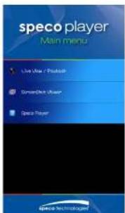
9-1-1. Live
- Open the installed "Speco Player" App and click action to add a remote device.
- Enter the site name, IP or DDNS address, Network Port number (default 5445), ID(default admin) and Password that is same with DVR setup password. Then, click "Save" button.
| About | Device List | + |
| Demo DS | > | |
| Demo HS | > | |
| Demo NSP | > |
* Note: Network Port and Web Port must be forwarded before adding a new site.

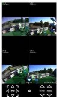
- The app will display the selected channel(s). Double tap the channel screen to switch 1 channel display to 4, 8, 10, 16 channels split display depending on the DVR.
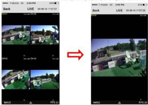
- To select the display mode(1, 4, 9, 10 or 16 split display), tap the arrow menus button

natural_image
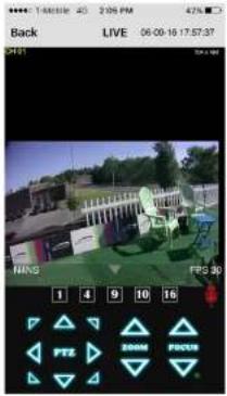
Exterior view of a modern office building (no signage)9-1-2.PTZ Control
To control the PTZ functions of the camera, tap the menu button. Then PTZ menu icons will display. Using the PTZ icon on the screen, can control PTZF functions.
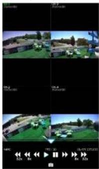
9-1-3. Playback
- Select mode as 'Playback' and click 'Connect' button. Then select Date & Time and click 'Connect' button.

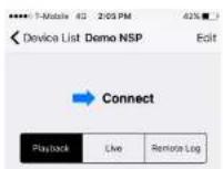

natural_image
Four-panel image showing outdoor scenes with buildings and greenery, no visible text or symbols→

natural_image
Outdoor scene with green outdoor furniture and a building, no visible text or symbols- Tap the menu button. Then Playback menu icons will display.

9-2. App Viewer for Android Phone
- Enter the Android Play Store.


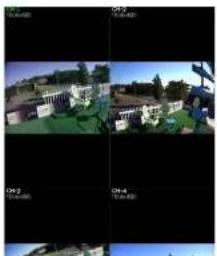
- The app will display the selected channel(s). Double tap the channel screen to switch 1 channel display to 4 channels split display.
natural_image
Four-panel collage showing a residential building with green roof, surrounded by outdoor scenes and camera interface elements (no readable text or symbols)9-2-2. Playback
-
Select the registered double and select 'Blay book' and select up to 4 channels to search. Then all ask 'Start'
-
The app will display the selected channel(s). Double tap the channel screen to switch 1 channel display to 4 channels split display.
natural_image
Four-panel image grid showing outdoor scenes with buildings and greenery, no visible text or symbols9-2-3.PTZ Control
To control the PTZ function of the camera, tap the channel screen, and then the channel name will be highlighted in Light Green. Using the PTZ menu icons on the screen, control PTZF.
natural_image
Four-panel image showing a residential building with green roof and surrounding greenery, alongside a camera lens (no visible text or symbols)
APPENDIX: Network Connection - LAN
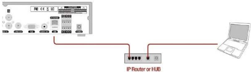
- Install the network client software from the supplied CD.
- Check the IP address from SETUP > SYSTEM > DESCRIPTION or SETUP>NETWORK of DVR.
- Run the network client software.


APPENDIX: Network Connection – Internet and DDNS
Dynamic Domain Name System (DDNS) allows a domain name to be constantly synchronized with a dynamic IP address. A current dynamic IP address is being associated with a static domain name.
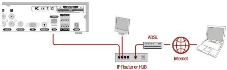
flowchart
graph TD
    A["PC"] --> B["IP Router or HUB"]
    B --> C["ADSL"]
    C --> D["Internet"]
    D --> E["Laptop"]
- Go to SETUP>NETWORK>DDNS and set the DDNS SERVER to ON.

If you set ezDDNS to ON, the host name is automatically generated and registered.
- Go to SETUP>NETWORK>DDNS>HOST NAME. Manually enter a domain name using the virtual keyboard and click ENTER button.

- When you exit SETUP menu, DDNS NOTIFY window will pop up.

- DDNS registration status can be checked from SYSTEM INFORMATION or SETUP>SYSTEM>DESCRIPTION>DDNS STATUS

- Check the NETWORK PORT (Default: 5445), WEB PORT (Default: 80), and the IP Address of the DVR from SETUP>NETWORK.
9. Run the network client software.

-
Input Site Name, Site Address (IP address), Port No., and Password on the connect window.
-
Site Name: Input a name that properly describes a site.
• IP Address: Domain name or Public IP address of a router that DVR is connected.
• Port Number: Default Port Number is "5445".
• ID: Input ID of DVR. Default ID is "admin". -
Password: Input network password of DVR that is same with DVR setup password.
-
And select the OK button. Then, press _button after checking the left check box.

- Cautions
- Explanation of Graphic Symbols
- WARNING
- These Precautions must be followed for Safety Reasons
- Product Components
- Table of Contents
- Main Features
- Initial Boot up Process
- 2-1. Initial Boot up and Basic Time Setup
- 2-2. Setting Daylight Saving Time
- 2-3. Setting NTP (Network Time Protocol)
- 2-4. EZ Setup
- Setup Date/Time and Record configuration
- EZ Network (Using an internet connection)
- Name, Function and Connection
- 3-1. Front Panel
- 3-2. Connectors
- 3-3. Remote Control
- Setting up the DVR
- 4-1. Setup - Main Live Screen
- 4-2. Setup - System Mode
- Caution
- Client Access
- NTP
- Setup
- e-Mail Setup
- System Event Notification
- Health Check
- 4-3. Setup - Record Mode
- 4-3-1. Recording Schedules
- 4-4-3. Spot Out
- 4-4-4. Motion Zone Setup
- 4-5. Setup - Display Mode
- 4-6. Setup - Network Mode
- 4-6-1. Network Types
- 4-6-1-1. DHCP
- 4-6-1-2. Static
- NOTE
- 4-6-3. Network Port and Web Port
- 4-7. Setup - User Management Mode
- 4-8. Setup - Storage Mode
- 4-9. Setup - Config Mode
- 4-9-1. Software Upgrade
- NOTICE
- Live, Search and Playback
- 5-1. Live View
- 5-1-1. PTZ Control
- 5-2. Digital Zoom in Live and Playback Screen
- 5-3. Search Screen
- 5-3-1. EZSearch
- 5-3-2. Time Line Search
- 5-3-3. Event Search
- 5-3-4. Go To First Time
- 5-3-5. Go To Last Time
- 5-3-6. Go To Specific Time
- 5-3-7. Archive List
- 5-3-8. Log List
- 5-4. Playback Mode
- Export and Back Up
- 6-1. Still Image Backup onto USB Flash Drive
- 6-2. Video Backup onto USB Flash Drive during playback
- 6-3. EZCopy: Video Backup onto USB Flash Drive during playback
- 6-5. Playback of Backup Video
- 6-5-1. AVI Format
- 6-5-2. NSF Format
- Network Access Using the Multi-Sites Network Viewer
- 7-1. Overview
- 7-2. PC Requirements
- 7-3. Installation of the Program
- 7-4. Live Window
- 7-4-1. Main User Interface
- 7-5. Search and Playback Window
- 7-5-1. Main User Interface
- 7-5-3. SMART SEARCH
- 7-6. Setup of SpecoTech Multi Client
- 7-6-1. General
- Miscellaneous
- 7-6-2. Event
- 7-6-3. Record
- 7-6-4. Display
- 7-6-5. Language
- 7-6-6. About
- 7-7. Remote Setup
- 7-7-1. System
- 7-7-2. Record
- 7-7-3. Device
- 7-7-4. Display
- 7-7-5. Network
- 7-7-6. User Management
- 7-7-7. Storage
- 7-8. Operation
- 7-8-1. Addition, Delete, and Modify of DVR Sites
- 7-8-1-1. Addition of Sites
- 7-8-2. Connect and Disconnect
- 7-8-2-1. Connect
- 7-8-2-2. Disconnect
- 7-8-3. Still-image Capture During Live
- 7-8-4. Recording Video on Local PC During Live
- 7-8-5. Local Playback and Remote Playback
- 7-8-5-1. Playback of Recorded Video on a Local PC
- 7-8-5-2. Playback of Recorded Video on Remote DVR
- 7-8-6. AVI Backup during Playback
- Network Access Using the Web-Browser Viewer
- Network Access Using the Smart Phone Viewer
- 9-1. App Viewer for iPhone
- 9-1-1. Live
- 9-1-2.PTZ Control
- 9-1-3. Playback
- 9-2. App Viewer for Android Phone
- 9-2-2. Playback
- 9-2-3.PTZ Control
- APPENDIX: Network Connection - LAN
- APPENDIX: Network Connection – Internet and DDNS
- Run the network client software.
Brand : Speco Technologies
Model : D4WVNP
Category : Surveillance Camera