
D8WHUM - Surveillance Camera Speco Technologies - Free user manual and instructions
Find the device manual for free D8WHUM Speco Technologies in PDF.


| Product Type | 8 Channel Hybrid HD-TVI & IP Full DVR |
| Model | D8WHUM (based on D8HU) |
| Video Input | Up to 8 channels HD-TVI, Analog, or IP (max 8MP per channel) |
| Max Recording Resolution | 3840 x 2160 (8MP) at up to 160fps (D8HU) |
| Video Compression | H.264 High Profile |
| Audio | 8 local audio inputs, 1 RCA output, G.711 codec |
| Storage | Up to 4 internal HDDs (max 8TB each), 1 e-SATA, USB backup |
| Network | Dual 10/100/1000 Base-TX ports, DDNS (free Speco DDNS), HTTPS |
| Remote Access | Multi-site client software, web browser (IE), smartphone app (iOS/Android) |
| PTZ Control | RS-485, UTC (coax), supports multiple protocols |
| Alarm I/O | 8 sensor inputs, 2 alarm outputs (D8HU) |
| Playback Features | EZSearch, Smart Search, timeline, event log, digital zoom |
| Backup | USB flash drive, external HDD, network; formats: BMP, AVI, proprietary |
| Power Supply | External power adapter (specifics not provided; typical 12V DC) |
| Operating Temperature | Not specified in manual; typical range 0°C to 40°C |
| Dimensions | Not specified in manual; approximate 1U rackmount size |
| Weight | Not specified in manual; approximate 3-4 kg |
| Safety Precautions | Do not disassemble; avoid moisture, shock, blocked vents; use qualified personnel for installation |
| Maintenance | Keep vents clean; do not move while powered; format HDD as needed |
| Spare Parts & Repairability | Contact Speco Technologies service center; no user-serviceable parts inside |
Frequently Asked Questions - D8WHUM Speco Technologies
User questions about D8WHUM Speco Technologies
0 question about this device. Answer the ones you know or ask your own.
Ask a new question about this device
Download the instructions for your Surveillance Camera in PDF format for free! Find your manual D8WHUM - Speco Technologies and take your electronic device back in hand. On this page are published all the documents necessary for the use of your device. D8WHUM by Speco Technologies.
USER MANUAL D8WHUM Speco Technologies
User's Guide (Ver. 1.0)
Models: D8HU/D16HU
8/16 Channel Higher MP HD-TVI & IP Full Hybrid DVR
Cautions

Explanation of Graphical Symbols

This symbol indicates the presence of important operating and maintenance (servicing) instructions in the literature accompanying the product.

This symbol indicates the presence of "dangerous voltage" within the product's enclosure that may be of sufficient magnitude to constitute a risk of electric shock, property damage, personal injury, or death.
These precautions MUST be followed for safety reasons

Warning
- Do not use if the unit emits smoke.
- Do not disassemble the unit.
- Do not place any heavy or sharp objects on the unit.
- Do not place on uneven surface.
- Do not expose to shock or vibration.
- Do not move the unit when the unit is powered on.
- Do not block, and allow dust to accumulate in the air vents.
- Do not restrict airflow of the unit; doing so can damage the unit.
- Only qualified and experienced personnel should perform installation and servicing.
- Turn off the power of the HU when connecting Cameras, Audio or Sensor Cables.
- The manufacturer is not responsible for any damage caused by improper use of the product or failure to follow instructions for the product.
- The manufacturer is not responsible for any problems caused by or resulting from the user physically opening the HU for examination or attempting to repair the unit.
Product Components
Please make sure the following components are included as specified below.
| DVR UnitDesktop: D8HU / D16HU | 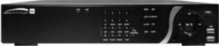 |
| Remote Control |  |
| Battery 1.5V (AAA x2) |  |
| Quick Setup Guide |  |
| Quick User Guide |  |
| USB Mouse |  |
Specifications
| MODEL NAME D8HU D16HU | |||||
| Operational Mode (HD-TVI, Analog, IP) Flexible for all channels | |||||
| Video Input HD-TVI Up to 8 Up to 16 | |||||
| Analog Up to 8 Up to 16 | |||||
| IP Camera Highest Resolution | Max. 3840x2160 (8MP) Max. 3840x2160 (8MP) | ||||
| Output Main Monitor VGA(Max. 1920x1080) and HDMI (Max. 3840x2160) | |||||
| Sub Monitor CVBS or SPOT | |||||
| HD-TVI, Analog Loop Output | 8 16 | ||||
| Audio Input Local Input 8 16 | |||||
| Remote Input from IP Camera | 8 16 | ||||
| Output Local Output (RCA) 1 | 1 | ||||
| Audio Codec | G.711 | ||||
| I/O | Sensor In | Local Input (Terminal Block) | 8 16 | ||
| Remote Input from IP Camera | 8 16 | ||||
| Alarm Output | 2 4 | ||||
| Serial RS-232C None | |||||
| RS-485 | 1 | ||||
| Recording | Compression | H.264 | |||
| Local Resolution & Frame Rate | 3840x2160 | 80fps 112fps(Ch1~8), | 160fps@QHD (Ch9~16) | ||
| Playback Speed x0.25, x0.5, x2, x4, x8, x16, x32, x64 | |||
| Backup Media | USB drive, External HDD, Network | ||
| File Format BMP, AVI, Proprietary Format | |||
| Huge Backup Yes (Max. 24 hours) | |||
| Storage HDD | Capacity of 1 HDD | 8TB | |
| Internal HDDs 4 | |||
| e-SATA 1 | |||
| USB Front 2 | |||
| Rear 1 | |||
| User I/F Input | Method Front Buttons, IR, Mouse, Keyboard Controller | ||
| Network | Private (IP Camera, Auto Connection) | 10/100/1000 Base-TX | |
| LAN (IP Camera or Remote Access) | 10/100/1000 Base-TX | ||
| Dynamic DNS | Yes (Free Speco DDNS) | ||
| Dual Encoding for Network | Yes | ||
| Features | Digital Zoom | Yes | |
| DLS (Day Light Saving) | Yes | ||
| NTP (Network Time Protocol) | Yes | ||
| S.M.A.R.T | Yes | ||
| EZNetwork / EZRecord / EZSearch / EZCopy / EZCamera | Yes | ||
| Internal Beep | Yes | ||
| e-mail Notification | Yes | ||
| Cloud Archiving | Yes | ||
| Twitter Mass Alert | Yes | ||
| HTTPS | Yes | ||
Table of Contents
- Main Features 9
- Initial Boot-up Process.... 10
2-1. Initial Boot up and Basic Time Setup....10
2-2. Setting up Daylight Savings Time....11
2-3. Setting NTP (Network Time Protocol)....12
2-4.EZ Setup....15
2-5. IP Camera SETUP (through SpecoTech Web Viewer)....18
2-6. Dual Streaming....18
- Front and Rear Panels 19
3-1. Front Panel 19
3-2. Rear Panel Connectors....20
3-3. Remote Control....21
- Setting up the DVR....22
4-0. Setup – Main Live Screen....22
4-1. Setup – IP CAMERA....23
4-2. Setup - SYSTEM....28
4-3. Setup – RECORD Mode 35
4-4. Setup - DEVICE Mode 37
4-5. Setup - DISPLAY Mode 43
4-6. Setup – NETWORK Mode .... 45
4-7. Setup – USER MANAGEMENT Mode .... 48
4-8. Setup - STORAGE Mode 51
4-9. Setup - CONFIG Mode....53
4-9-1. Firmware Upgrade ....54
6-1. Still Image Backup onto USB Flash Drive....67
6-2. Video Backup onto USB Flash Drive during playback 68
6-3. EZCopy: Video Backup onto USB Flash Drive during playback....69
6-4. Transferring Still Images or Video from the ARCHIVE List....70
6-5. Playback of Backup Video ....71
- Network Access Using the Multi-Sites Network Viewer 72
7-1. Overview....72
7-2. PC Requirements....72
7-3. Installation of the Program....73
7-4. Live Window....74
7-5. Search and Playback Window ....76
7-6. Setup of SpecoTech Multi Client....81
7-7. Remote Setup 86
7-8. Operation....93
-
Network Access Using the Web-Browser Viewer.... 102
-
Network Access Using the Smart Phone Viewer.... 104
9-1. App Viewer for iPhone....104
9-2. App Viewer for Android Phone....107
APPENDIX: Network Connection - LAN 110
APPENDIX: Network Connection – Internet and DDNS....112
1. Main Features
■ Easy Record, Copy and Setup
■ Easy Search by Thumbnail Preview
■ Easy Network
■ Easy IP Camera Setup
■ Recording Rate: D16HU: 400fps @ QHD, D8HU: 160fps @ QHD
■ Digital Deterrent, audio message output upon event
■ H.264 High Profile compression saves HDD space
■ Simultaneous live view/playback while continuing to record/network transfer or backup
■ Remote monitoring/recording/playback/configuration and control via internet
■ Audio Recording: D16HU:16 Channels, D8HU:8 Channels
■ Switch between low and high quality stream during simultaneous Continuous + Motion or Continuous + Sensor recording modes for storage optimization
NOTE: Under federal law, The Fourth Amendment to the U.S. Constitution, Title III of the Omnibus Crime Control and Safe Streets Act of 1968, as amended by the Electronic Communications Privacy Act of 1986 (18 U.S.C. § 2510, et seq.), and the Foreign Intelligence Surveillance Act of 1978 (50 U.S.C. 1801, et seq.) permit government agents, acting with the consent of a party to a communication, to engage in warrantless interceptions of telephone communications, as well as oral and electronic communications.
■ Automatic camera detection (Plug & Play)
■ Covert camera operation provides enhanced security and administrator control
■ Dynamically programmable recording priority, motion detection, alarms and scheduling
■ Simple and Easy Graphic User Interface
■ Simple Schedule Recording
■ HDMI Output
2. Initial Boot-up Process
2-1. Initial Boot up and Basic Time Setup
- During the first boot up, the following logo will be displayed.

- After the logo, select the language and set date and time as specified below.

1) User has to set a password before using.
Can not use '1111' when the initial boot up password set.
But user can set '1111' as a password through [Setup > User Management > Password Setup]
2) DVR will not proceed when user put the password '1111'.

bar
| Category | Value (%) | |---|---| | Initialize the system | 90 | | Initialize Network .... Done | (Not labeled) |2-2. Setting up Daylight Savings Time
To enable Daylight Saving feature/NTP synchronization, take the following steps.
- Enter the Setup mode. The default Username is "admin" and enter a password set on the initial boot-up process.
Search
Setup
Display
Aspect Ratio
Snapshot
Super EZ Copy
Enable Manual Record
Instant Playback
Advanced Menu

- Go to SETUP > SYSTEM > DATE & TIME SETUP

3. Select ON from the DAYLIGHT SAVING dropdown menu.
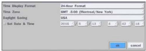
2-3. Setting NTP (Network Time Protocol)
- SETUP > SYSTEM > NTP SETUP > ON
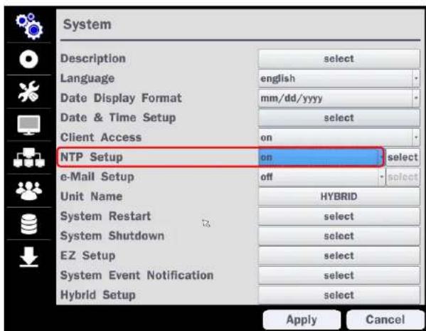
Table2.3.1. GMT Time Zone
| State Standard Time | Daylight-Saving Time | ||
| AL Alabama GMT-6 GMT-5 | |||
| AK Alaska GMT-9 GMT-8 | |||
| AK Alaska (Aleutian Islands) GMT-10 | NA | ||
| AZ Arizona GMT-7 | NA | ||
| AZ Arizona (Navajo) | GMT-7 | GMT-6 | |
| AR | Arkansas | GMT-6 | GMT-5 |
| CA | California | GMT-8 | GMT-7 |
| CO | Colorado | GMT-7 | GMT-6 |
| CT | Connecticut | GMT-5 | GMT-4 |
| DC | District of Columbia | GMT-5 | GMT-4 |
| DE | Delaware | GMT-5 | GMT-4 |
| FL Florida | GMT-5 | GMT-4 | |
| FL | Florida (W) | GMT-6 | GMT-5 |
| GA | Georgia | GMT-5 | GMT-4 |
| HI | Hawaii | GMT-10 | NA |
| ID | Idaho (N) | GMT-8 | GMT-7 |
| ID | Idaho (S) | GMT-7 | GMT-6 |
| IL | Illinois | GMT-6 | GMT-5 |
| IN | Indiana | GMT-5 | GMT-4 |
| IN | Indiana (SW / NW) | GMT-6 | GMT-5 |
| IA | Iowa | GMT-6 | GMT-5 |
| KS | Kansas | GMT-6 | GMT-5 |
| KS | Kansas (W) | GMT-7 | GMT-6 |
| NH New Hampshire GMT-5 GMT-4 | |||
| NJ New Jersey GMT-5 GMT-4 | |||
| NM New Mexico GMT-7 GMT-6 | |||
| NY New York GMT-5 GMT-4 | |||
| NC North Carolina GMT-5 GMT-4 | |||
| ND North Dakota GMT-6 GMT-5 | |||
| ND | North Dakota (W) | GMT-7 GMT-6 | |
| OH | Ohio | GMT-5 GMT-4 | |
| OK | Oklahoma | GMT-6 | GMT-5 |
| OR | Oregon | GMT-8 | GMT-7 |
| OR Oregon (E) GMT-7 GMT-6 | |||
| PA | Pennsylvania | GMT-5 GMT-4 | |
| RI | Rhode Island GMT-5 GMT-4 | ||
| SC | South Carolina | GMT-5 | GMT-4 |
| SD | South Dakota (E) | GMT-6 | GMT-5 |
| SD | South Dakota (W) | GMT-7 | GMT-6 |
| TN Tennessee (E) GMT-5 GMT-4 | |||
| TN | Tennessee (W) | GMT-6 | GMT-5 |
| TX | Texas | GMT-6 | GMT-5 |
| TX | Texas (W) | GMT-7 GMT-6 | |
| UT | Utah | GMT-7 GMT-6 | |
| VT | Vermont | GMT-5 GMT-4 | |
| VA | Virginia | GMT-5 | GMT-4 |
| WA | Washington GMT-8 | GMT-7 | |
| WV | West Virginia GMT-5 | GMT-4 | |
2-4. EZ Setup
Quick installation Menu for HU and IP Camera Easy installation(Right-Click on the Main Screen)
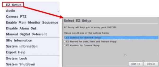
Figure 2.4. EZ Setup Screen
2.4.1. Setup EZ Record, Date & Time, and IP Camera configurations.
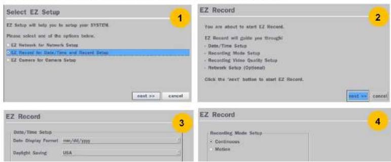


Figure 2.4.1. EZ Record Setup Procedure
① Select EZ Record for Date/Time and Recording Setup, and click "next" to proceed.
② When the description of EZ Record Setup is displayed, click "next" to proceed.
③ Set up the Date/Time settings and click "next" to get to the recording setup.
④ Select the recording mode and click "next" to get to the record video quality setup.
⑤ After setup the Record Video Quality, click "next" to to proceed.
⑥ To close the setup page click "finish" or "go to ez camera" to set up IP Camera.
⑦ Configure individual cameras in the EZ Camera Setup.
- Select the Channel to configure.
- Select the Camera Protocol, and then click "select" on Scan menu. (This will scan the network for any IP cameras using the specified protocol.)
- Select the desired IP camera from the list, and then click on "register".
- If necessary, click on "Preview" to preview the camera, or Setup to change camera settings.
2.4.2. EZ Network (Using an internet connection)
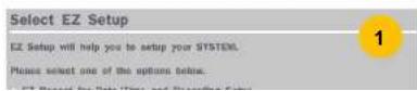
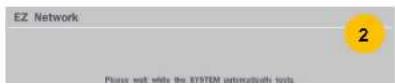
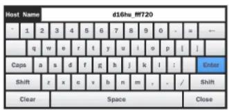
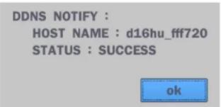
Figure 2.4.2. EZ Network Setup Procedure
① DVR automatically checking the network and configuration by scanning in few seconds.
② DVR will show the DDNS host name when configuration is finished automatically.
③ If you need to edit the host name please select 'edit' button.
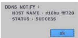
④ Everything is OK, then select 'finish'. Host name and status pop-up screen will be showed.
2-5. IP Camera SETUP (through SpecoTech Web Viewer)
HU Series allows remote access to the IP Cameras through "IP Camera Setup" menu in SpecoTech Web Viewer.

① Click the mouse right button
② Select "IP Camera Setup".
③ Select Channel Number.
④ It launches the camera's web setup page.
In order for the web pages to launch from the "IP Camera Setup" menu when accessed from the WAN, Ports 59011 to 59254 on the router must be port forwarded to the HU. The local address of the HU can be found in the system information.
2-6. Dual Streaming
- High Quality (Main Profile) Video Stream is used for both Recording and Live Display.
3. Front and Rear Panels
3-1. Front Panel

Figure 3.1.1. DVR Front panels
Table 3.1.1. Front LED and Ports of Desktop Models (D16HU/D8HU)
| Name Description | |
| POWER | LED light is on when power is applied to the system. |
| HDD | LED light is on when the system is recording video data. |
| USB Port | This USB port for archiving footage into a USB device. (USB 2.0 connector) |
Table 3.1.2. Front Buttons (D16HU/D8HU)
| Name Description | |
| Buttons 1~16 | Select a channel from CH1 to CH16 |
 | Buttons from 9 to 16 is used as function keys on PTZ control modeTo escape out of PTZ mode, press the ESC button. |
| MENU | Goes into the Setup window |
| COPY | Takes a Screenshot on Live View and Goes into Backup during Playback |
3-2. Rear Panel Connectors

- Do not power this system on before all the connections are attached.
- Make sure all the connections are properly secured. Faulty connection may result in the system being damaged.
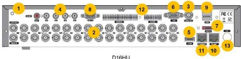
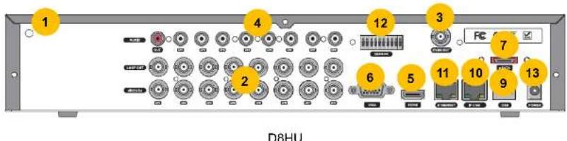
Figure 3.2.1. Connectors
① Ground: Use for ground port.
② VIDEO IN: Video input port.(For HD TVI & Analog 960H cameras)
③ VIDEO OUT: MAIN – Composite Video Output / SPOT – Spot Monitor
④ AUDIO IN & OUT: Connectors for audio input and one connector for audio output
3-3. Remote Control
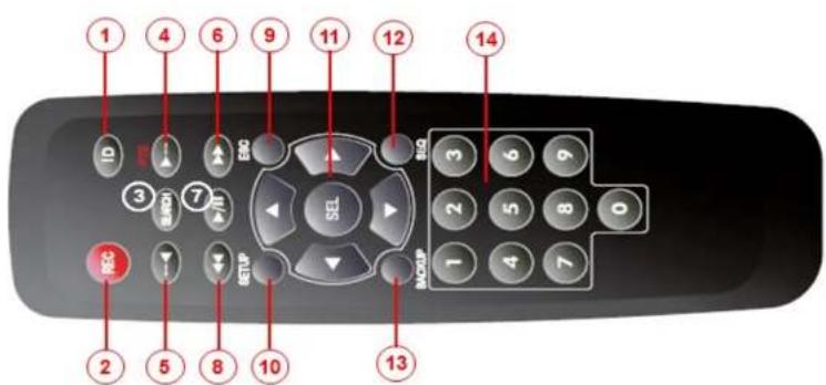
Typical Remote Control
① ID: To set the remote control ID.
② REC: To start and stop manual recording
③ SEARCH: To go to SEARCH menu.
④ F/ADV:
- During playback – To move the playback position 60 seconds forward.
- During Pause – To move the playback position moves 1 frame forward
⑤ F/REW:
- During playback – To move the playback position 60 seconds back.
- During Pause – To move the playback position 1 frame back.
⑥ FF: To fast forward the recording
4. Setting up the DVR
The following sections detail the initial setup of the DVR.

Menu screen will close if user response is not received in 5 minutes.
4-0. Setup - Main Live Screen
To enter the setup menu, right click on the mouse and select setup from the submenu or press the setup button on the remote control.

Search
Setup
Display
Aspect Ratio
Snapshot
Super EZ Copy
Enable Manual Record
Instant Playback
Advanced Menu
Figure 4.1 Live Screen and Quick Operation Window
![Login - Setup User ID admin Password: 1 2 3 4 5 6 7 8 9 0 - = - 6 w o r t y u l o p l ]](/content/2026/06/1216667/images/1f9f7b3596d71dc3c82e7115822253456dd692fb93d5dd5fab9ad62f43eb42d2.jpg)
4-1. Setup - IP CAMERA
Press the SETUP button and enter the password. The setup menu is displayed as picture below. Select IP Camera icon and press SEL button to enter the setup menu item.
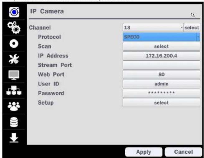
Figure 4.1.1 IP Camera mode setup screen
Table 4.1.1. Menu items in IP Camera mode setup
Item Description
CHANNE To manually connect each camera, click on the "select" to get this window:

IP Address: Enter the address of IP camera to connect, or select from scanned list.
Stream Port: Enter the port number of IP camera to connect
Web Port: Enter the web port number of IP camera to connect
Others: Change the IP camera setting. Double click the empty box and then Log-In box will be pop-up. (Enter ID and PASSWORD of IP Camera)
Protocol Select the protocol for the IP Camera
Scan Automatic IP Camera search on the local network.
IP Set up IP camera address.
Address
Stream Set up the RTSP port of the IP Camera (default: 554)
Port
Web Port Set up the web port of IP Camera (default: 80)
User ID Enter ID of IP Camera
Password Enter the Password of IP Camera
Setup Set up Video, Network and System of IP Camera
4-1-1. Scan Menu
Scan for IP Camera on network using SPECO/ONVIF/HIKVISION protocols.

Figure 4.1.2 IP Camera Setup Screen

Figure 4.1.3 Left Image using ONVIF Protocol Scan, Right Image using SPECO Protocol Scan
| Profile Name | Resolution | Frame Rate | Bit Rate | I-Frame Interval | H264 Profile |
| Profile1 | 3840 X 2160 | 30 | 6000 | 30 | Main |
| Profile2 | 640 X 360 | 15 | 1000 | 15 | Main |
4-1-2. ONVIF Setup Menu
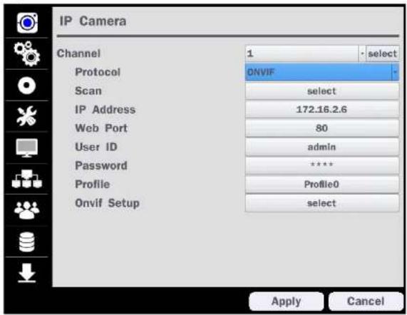
Figure 4.1.2 IP Camera Setup Screen (ONVIF)
The NS Series can search for IP Cameras that are conformant to ONVIF (Open Network Video Interface Forum).
In order to search for ONVIF Cameras, the field associated with VENDOR has to be set to ONVIF.
Click on the Box associated with Scan to scan the networks for ONVIF Conformance cameras.
| IP Address | Web Port | Device Information | Host Name |
| 172.18.7.11 | 60 | IPC | |
| 172.15.200.4 | 60 | IMH-181 | NOBRAND_IMH-181 |
| 172.10.200.12 | 60 | IMH-181 | NOBRAND_IMH-181 |
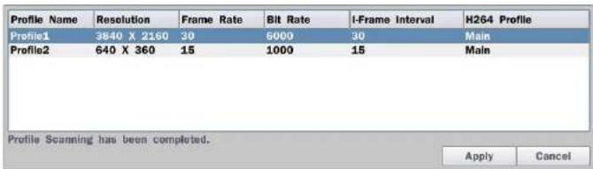
Figure 4.1.5 ONVIF Profile Scan Window
① Select ONVIF for Vendor and click the SCAN button.
② Select the camera on the list and then click the register button.
③ Then, PROFILE and ONVIF setting button will be displayed on the menu.
Click PROFILE button and then the detail information of ONVIF will be searched and listed.
(If there is not one listed, the ONVIF protocol of IP CAM is not compatible with Hybrid DVR and therefore not supported.)
④ Double click the listed profile to apply.
⑤ Enter ID and PASSWORD of IP CAM. Registration is .completed.
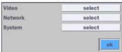
Figure 4.1.6 ONVIF Setup Window
Under ONVIF Setup. the following can be viewed and changed: VIDEO. NETWORK. SYSTEM settings.
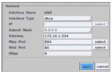
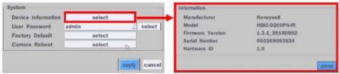
SYSTEM
System information and change your password, factory reset and the camera is rebooting.
4-2. Setup - SYSTEM
In the SETUP menu, select the SYSTEM tab. Then, the SYSTEM menu is displayed as pictured below. Navigate through the menu items using the mouse or the remote control and change the value of the menu.

Table 4.2.1. Menu Items in SYSTEM Setup Screen
| Item Description | |
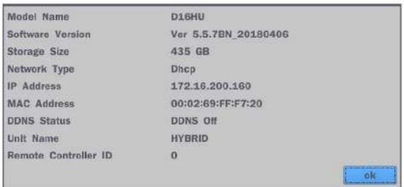
| DESCRIPTION | Press the button to view the system information. (Software Version, Storage Size, IP Address, MAC Address and DDNS Status) |
| Model Name D16HUSoftware Version Ver 5.5.7BN_20180406Storage Size 435 GBIP Address 172.16.200.146MAC Address 00:02:69:FF:F7:20DDNS Status Ready - d16hu_ff720ok | |
| LANGUAGE | Select the display language using the mouse or the remote control. Once a language is selected, the display language will change. |
| DATE DISPLAY FORMAT | Select the date display format using the mouse or the remote control. Options are:MM/DD/YYYY, YYYY/MM/DD, DD/MM/YYYY, YYYY-MM-DD, MM-DD-YYYY, DD-MM-YYYY |
| DATE&TIME SETUP | Select the display date and time using the mouse or the remote control and press OK button to set the present date and time. |
Select DAVLIGHT SAVING using the mouse or the remote control and select the
over variable-latency data networks.
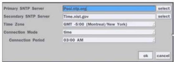
PRIMARY SNTP SERVER: Input the address of the primary NTP time-server.
SECONDARY SNTP SERVER: Input the address of the secondary NTP time-server.
TIME ZONE: NTP synchronizes with GMT (Greenwich Mean Time) regardless of geography, user must set their own time difference.
CONNECTON MODE: Select the NTP time-server connection mode from TIME, INTERVAL, and ONCE.
CONNECTION PERIOD
- TIME – Refresh the time at the designated time (e.g. 1AM)
- INTERVAL – Every 1 hour \~ 24 hours
- ONCE – Synchronizes time only once. NTP will not synchronize unless the Connection Mode is changed.
Sends E-MAIL Notification when the NTP server time is faster than the system time with bellow message.
"NTP server time is faster than the system time.
In this case, NTP server time is ignored to protect the user data.
User must set the time manually.
SYSTEM TIME: Mon Oct 10 13:46:49 2011
SERVER TIME: Mon Oct 10 13:33:12 2011

| MAIL PORT: Assign Mail Port number.SECURE OPTION: Select the secure mail server connection method. (SSL or TLS)ID: Enter the appropriate mail server ID.PASSWORD: Enter the appropriate mail server PASSWORDMAIL TO: Enter the appropriate email address to enable sending e-mail reports using a virtual keyboard.MAIL FROM: To set the email address sent to the destination host.TEST : E-mail settings sent a test mail to the registered account | |
| UNIT NAME | Name the HYBRID (e.g. Factory, Library, Store, Location etc)This is to used to identify the name of each DVR under the same network. |
| SYSTEM RESTART | Restart the system |
| SYSTEM SHUTDOWN | Shut down the system |
| EZ SETUP | Helps user to easily setup NETWORK, RECORDING and IP CAMERA |
| SYSTEM EVENT | Disk Event Setup |
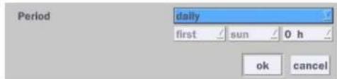
HEALTH CHECK - OFF, ON
(Allows the user to set MAIL STATUS periodically) : DAILY or WEEKLY or MONTHLY
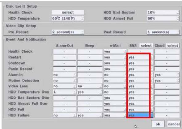
VIDEO CLIP SETUP: Setup the duration of video clip for PRE RECORD and POST RECORD.
EVENT AND NOTIFICATION - OFF, ON
(Allows the user to set EVENT NOFICIATION ON or OFF)
HEALTH CHECK / RESTART / SHUTDOWN / PANIC RECORD
- Enable Email Notification in the event a problem occurs with the VS. ALARM-IN – Enable Email Notification when the camera detects sensor. MOTION DETECTION – Enable Email Notification when the camera detects motion.
VIDEO LOSS – Enable Email, Beep and Alarm output Notification when the camera signal is lost.
HDD TEMPERATURE – Enable Email, Beep and Alarm output Notification when the HDD temperature.
HDD BAD SECTORS – Enable Email Notification when the HDD has bad Sectors.
HDD ALMOST FULL – Enable Email Notification when the HDD is almost full HDD FULL – Enable Email Notification when the HDD is full
HDD FAILURE – Enable Email, Beep and Alarm output Notification when the HDD fails.
1-4) Set Video clip duration

2) How to playback
2-1) Playback through PC
: Log in Google Drive and select a file and playback
2-2) Playback through Mobile device
: Use 'SpecoPlayer'
Notice – Support iOS from '1.5.8_150316', Android from '3.2.2.7_150316'
How to use 'SNS'
- Notice : User have to make an Twitter account for DVR in order to follow the Twitter followers.
- DVR send event message to Twitter followers when EVENT Triggered.
1) How to set (Setup - System - System Event Notification - SNS)
1) Message receiving (Following)
2) Message receiving (Following)
2-1) Follow the DVR twitter account
2-2) Followers can see received messages
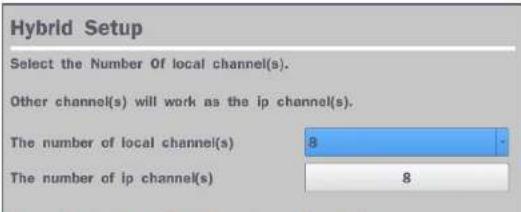
HYBRID SETUP
4-3. Setup - RECORD Mode
In the SETUP menu, select the RECORD tab. Then, the RECORD menu is displayed as pictured below.
Navigate through the menu items or change the settings using the mouse or the remote control.
Figure 4.3.1. RECORD Setup Screen
Table 4.3.1. Menu Items in RECORD Setup Screen
Menu Item Description
SITF
Select a channel for applying the following settings using the mouse or the remote
RESOLUTION Select HD TVI or 960H for analog cameras using the mouse or the remote control.
FRAME RATE Set the frame rate for the specified channel. The sum of the frame rate values from each channel cannot exceed the maximum frame rates for a specific recording resolution.
QUALITY Select the recording quality for the selected channel. Options are:
Level 1 (Low), Level 2, Level 3, Level 4, and Level 5 (High)
RECORDING Assign the recording mode for the selected channel. Options are: Continuous,
MODE Motion, Sensor, Schedule, Disable and Smart Recording (c + m : continuous & motion, c + s : continuous & sensor). When Motion Recording is selected, Continuous + Motion recording option can be used.
SENSOR Select the sensor setting for the selected channel.
RECORDING
PRE RECORD Enable/disable pre-event recording. Pre-event recording is limited to 20 minutes.
POST EVENT Set the post event recording time duration for the specified channel.
RECORD (10\~60 seconds)
AUDIO Enable/disable audio recording for the specified channel.
SCHEDULE To setup a recording schedule, select SCHEDULE in the RECORD menu. Navigate through the menu items or change the settings using the mouse or the remote control. Select CHANNEL > select NONE, CONTINUOUS, MOTION or SENSOR > Highlight area. To convert a schedule to a different channel, select the channel from
- NONE: Disable recording during selected timeframe (Highlighted in White)
• CONTINUOUS: CONTINUOUS recording (Highlighted in Green)
• MOTION: MOTION recording (Highlighted in Yellow)
• SENSOR: SENSOR recording (Highlighted in Red)
• CLEAR: Clears the schedule
4-4. Setup - DEVICE Mode
In the SETUP menu, select the DEVICE tab. Then, the device menu is displayed as pictured below. Navigate through the menu items or change the settings using the mouse or the remote control.
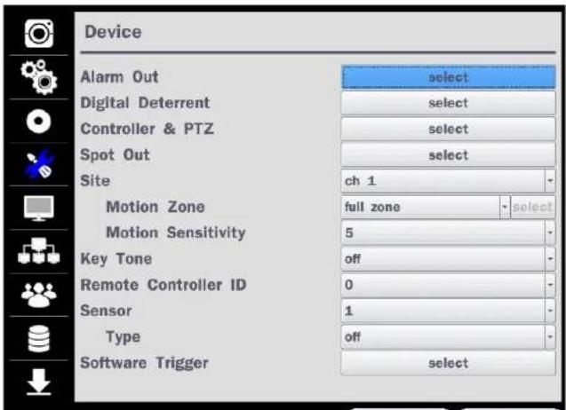
| SITE | Select specified channel for motion zone setup. |
| MOTION ZONE | Select either Full Zone or Partial Zone for motion detection. |
| MOTION SENSITIVITY | Set the motion sensitivity for the selected channel.Control the motion sensitivity from 1 to 9.(9 – Highest sensitivity, 1 – Lowest sensitivity) |
| KEY TONE | Enable/disable key tone from front panel usage. |
| REMOTE CONTROL ID | Set the remote control ID.1. Select ID.2. Input the remote control ID number.3. An icon will indicate on the Live Screen if the remote control ID is synchronized.The options are from 0 to 99 |
| SENSOR | Select the type of each sensor.Option is Off, Normal Open or Normal Close. |
| SOFTWARE TRIGGER | Remote trigger channels. User can set the channels that want to make a sensor recording through remotely with Software record mode. |
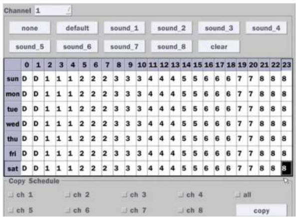
4-4-1. Digital Deterrent
Trigger audio message via motion detection or sensor
Select the play button to hear message after export.

SCHEDULE
Schedule the sound file considering the expected situation.
4-4-2. Keyboard Controller & PTZ Setup
To control the PTZ functions of the camera, connect the PTZ controller to the RS-485 port on the back of the chassis with CAT5 (or equivalent) cable.
① Connect the RS-485 cables of PTZ camera to the RS-485 port on the rear panel.
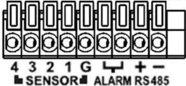
Figure 4.4.2.1. Device Mode Setup Screen
② Open the PTZ sub menu by selecting the submenu button.
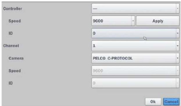

Figure 4.4.2.3 Controller Selection Screen
◆Notice: DxxHU series can use UTC feature.
: UTC(Up The Coax) allows for control of the camera OSD menu via the coax cable. User does not need extra connection via RS-485 to control the camera OSD menu - How to set (Setup > Device > PTZ & Controller > PELCO C-PROTOCOL)
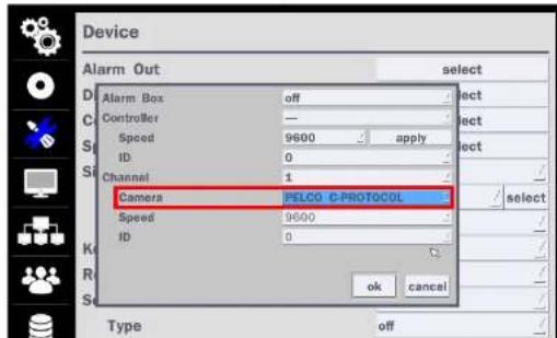
Table 4.4.3. Menu Item in SPOT-OUT Setup Screen
| Item Description | |
| SPOT ON EVENT | Enable/disable channel change if an event occurs on a channel. |
| SPOT EVENT | Set the dwell time for the display of the event activated channel. |
| DWELL TIME | (3-10sec) |
| SEQUENCE | Enable/disable sequential display of spot channel in full screen.If select ON, the selected channel will be displayed on the monitor periodically. |
| SEQUENCE | Set the dwell time for the spot channel display. (3-10sec) |
| DWELL TIME | |
| SPOT CHANNEL | Select a channel for spot monitoring using the mouse or the remote control and press OK button. |
4-4-4. Motion Zone Setup
Select MOTION ZONE using the mouse or the remote control and select either PARTIAL ZONE or FULL ZONE using the mouse control. The default value is FULL ZONE.
If FULL ZONE is selected, the motion zone grid screen is not displayed. Only set the level of sensitivity for MOTION SENSITIVITY.
FULL ZONE: The motion sensor is active on the whole screen.
PARTIAL ZONE: The motion sensor is active in the set detection frame.
Select the motion detection position using the mouse or the remote control. Then left click on the mouse or left click and drag the mouse pointer to select or deselect the area. Highlighted area indicates the partial motion detection zone. Press the ESC button or right click on the mouse to return to the previous menu.

natural_image
Interior architectural view of a modern building with diagonal light beams and horizontal windows (no visible text or symbols)4-5. Setup - DISPLAY Mode
In the SETUP menu, select the DISPLAY tab. Then, the DISPLAY menu is displayed as pictured below. Navigate through the menu items or change the settings using the mouse or the remote control. To return to the previous setup menu screen, press the Cancel button.
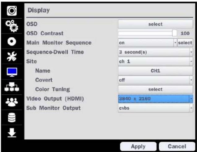
Figure 4.5. DISPLAY Setup Screen
Table 4.5. Menu Items in DISPLAY Setup Screen
Item Description

| SEQUENCE DWELL TIME | Set the dwell time of each, single channel display in sequential display mode (3~60seconds) |
| SITE | Select a channel to apply the name and covert settings change using the mouse or the remote control.Select a channel to apply the following settings using the mouse. |
| NAME | Set the channel name. Press the right square button and set the channel name and select OK using the mouse.The name can be made up to 36 characters. |
| COVERT | Enable/disable display of the specified video channel in live display. |
| COLOR TUNING | 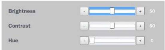 |
4-6. Setup - NETWORK Mode
Select the NETWORK tab. Then, the network menu is displayed as pictured below. Navigate through the menu items or change the settings using the mouse or the remote control.

Figure 4.6. NETWORK Setup Screen
Table 4.6. Menu Items in NETWORK Setup Screen
Item Description
NETWORK TYPE DHCP·DVR will automatically retrieve an IP address
| WEB PORT/ | Enter the port number for connection using web. |
| HTTPS PORT | (Default web port : 80, Default https port : 443) |
| NETWORK | Sets the camera display settings for network streaming. |
| STREAM |
4-6-1. Network Types
4-6-1-1. DHCP
An IP address is automatically assigned by the DHCP server, which automatically assigns the IP address and other parameters to new devices.
4-6-1-2. STATIC
IP address, Subnet Mask, Gateway, and DNS are manually assigned by the user.
- IP ADDRESS: The fixed IP address of the DVR unit.
- SUBNET MASK: The subnet mask for the LAN.
• GATEWAY: The IP address of the Gateway.
• DNS (PRIMARY) The primary address of Domain Name Server
• DNS (SECINDARY): The secondary address of Domain Name Server

NOTE
Unless DNS is properly set, the DDNS and the e-mail features will not work.
4-6-2. DDNS
DDNS (Dynamic Domain Name System) allows a DNS name to be constantly synchronized with a dynamic IP address. It allows using a dynamic IP address to be associated with a static domain name.
Once the setting is completed, the DDNS address will be:
http://hostname.ddns.specoddns.net
Table 4.6.2. DDNS
| Item Description | |
| ENABLE DDNS | Turn DDNS on/off |
| HOST NAME | This item allows the user to setup a domain name manually, using virtual keyboard displays as shown. |
| SUBMIT/UPDATE | When manual host name input is done, move the cursor to this item and select ON to submit the settings. |
| ezDDNS | Enable/disable ezDDNS to register the host name automatically. |
4-6-3. Network Port and Web Port
Connecting DVR/DVRs through a common IP sharing device, each DVR must be assigned a unique TCP port number for access from outside the LAN. This port number is displayed on NETWORK>NETWORK PORT Setup MENU.

NOTE:
If you access the DVR only within the same LAN, the TCP port number does not need to be changed.
Network access beyond a router
To access DVR beyond a router (firewall), you must open the proper TCP ports for live/playback streaming, for commands, for remote backup, and for audio streaming. If these ports are not opened properly, can't access the DVR beyond a router.
you

For live/playback streaming, for commands, for remote backup: Open the port number on NETWORK>NETWORK PORT menu. The default port number is 5445.
For bi-directional audio: Open the port number on NETWORK AUDIO PORT. The default port number is [NETWORK PORT number + 1].
- For web viewer downloading and remote firmware upgrading: Open the port number on
| Net Resolution | Frame Rate | Net Quality | |
| All | 640x360 | 15 fps | level 5(H) |
| 1 | 640x360 | 15 fps | level 5(H) |
| 2 | 640x360 | level 5(H) | |
| 3 | 640x360 | level 5(H) | |
| 4 | 640x360 | level 5(H) | |
| 5 | 640x360 | level 5(H) | |
| 6 | 640x360 | level 5(H) | |
| 7 | 640x360 | level 5(H) | |
| 8 | 640x360 | level 5(H) | |
| 9 | 640x360 | level 5(H) | |
| 10 | 640x360 | level 5(H) | |
| 11 | 640x360 | level 5(H) | |
| 12 | 640x360 | level 5(H) | |
| 13 | 640x360 | level 5(H) | |
| 14 | 640x360 | level 5(H) | |
| 15 | 640x360 | level 5(H) | |
| 16 | 640x360 | level 5(H) | |
| okcancel | |||
Figure 4.6.4. NETWORK Setup Screen – Network Stream
4-7. Setup - USER MANAGEMENT Mode
In the SETUP menu, select the USER MANAGEMENT tab. Then, the USER MANAGEMENT menu is displayed as pictured below. Navigate through the menu items or change the settings using the mouse or the remote control.

Table 4.7. Menu Items in USER MANAGEMENT Setup Screen
Item Description
AUTHORITY
SETUP
Only the Admin will have access to the menu.
PASSWORD CHECK: Select the Checkbox to enable the functions or leave the Checkbox blank to disable the functions.
- SETUP: Enable/Disable of access to Setup
- PB: Enable/Disable of access to Playback
- PTZ: Enable/Disable of access to PTZ Control
• REC OFF: Enable/Disable of manual Record
• NETWORK: Enable/Disable of access to Network
Selected Checkbox: The DVR will ask for a password when the given function is selected for all users.
Blank Checkbox: The DVR will not ask for a password when the given function is selected for all users.
| Password | Setup | PB | PTZ | Rec Off | Network | |
| Password Check | ✘ | ✘ | ✘ | ✘ | ✘ | |
| ADMIN | ✘ | ✘ | ✘ | ✘ | ✘ | |
| USER1 | 1111 | ✘ | ✘ | ✘ | ✘ | ✘ |
| USER2 | 1111 | ✘ | ✘ | ✘ | ✘ | ✘ |
| USER3 | 1111 | ✘ | ✘ | ✘ | ✘ | ✘ |
| USER4 | 1111 | ✘ | ✘ | ✘ | ✘ | ✘ |
| USERS | 1111 | ✘ | ✘ | ✘ | ✘ | ✘ |
| USER6 | 1111 | ✘ | ✘ | ✘ | ✘ | ✘ |
| USER7 | 1111 | ✘ | ✘ | ✘ | ✘ | ✘ |
| USER8 | 1111 | ✘ | ✘ | ✘ | ✘ | ✘ |
| USER9 | 1111 | ✘ | ✘ | ✘ | ✘ | ✘ |
"PASSWORD CHANGED" is displayed.
It is highly recommended to assign a new password to protect the system.
AUTHORITY OF
Set authority level of playback on each user.
PLAYBACK
Checked box: authorized to playback. Blank check box: no authority.
| 1 | 2 | 3 | 4 | 5 | 6 | 7 | 8 | |
| ADMIN | ✘ | ✘ | ✘ | ✘ | ✘ | ✘ | ✘ | ✘ |
| USER1 | ✘ | ✘ | ✘ | ✘ | ✘ | ✘ | ✘ | |
| USER2 | ✘ | ✘ | ✘ | ✘ | ✘ | ✘ | ✘ | ✘ |
| USER3 | ✘ | ✘ | ✘ | ✘ | ✘ | ✘ | ✘ | ✘ |
| USER4 | ✘ | ✘ | ✘ | ✘ | ✘ | ✘ | ✘ | ✘ |
| USERS | ✘ | ✘ | ✘ | ✘ | ✘ | ✘ | ✘ | ✘ |
| USER6 | ✘ | ✘ | ✘ | ✘ | ✘ | ✘ | ✘ | ✘ |
| USER7 | ✘ | ✘ | ✘ | ✘ | ✘ | ✘ | ✘ | ✘ |
| USER8 | ✘ | ✘ | ✘ | ✘ | ✘ | ✘ | ✘ | ✘ |
| USER9 | ✘ | ✘ | ✘ | ✘ | ✘ | ✘ | ✘ | ✘ |
REMOTE
Disconnect the remote playback after the specific time (Disable, 5min, 10min, 15 min, 30min, 60min.
PLAYBACK
TIMEOUT
IMPORT
Upload https certificate through USB
CERTIFICATATE
FROM USB
ADVANCED
Send IP address and ports information to the control center
SETUP
DEBUG PORT
Open or Close the ports for remote checking
Network
Shows the current network connection status (User, IP Address, Date/Time).
Connection
And do disconnect the user's network connection to click 'disconnect' button
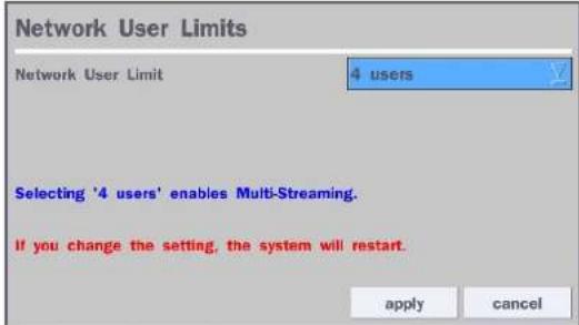
Network User Limits
User can select network access user number (4 users of 12 users). DVR system will be restarted if user change this network user numb
4-8. Setup - STORAGE Mode
In the SETUP menu, select the STORAGE tab. Then, the STORAGE menu is displayed as pictured below. Navigate through the menu items or change the settings using the mouse or the remote control.
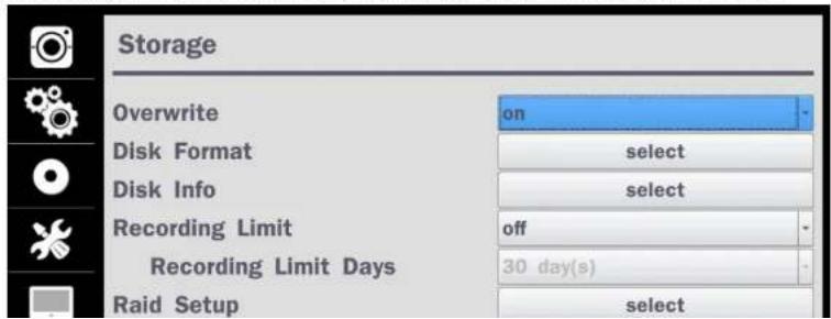
Table 4.8. Menu Items in STORAGE Setup Screen
| Item Description | |||
| OVERWRITE | When enabled, the DVR will continue recording and overwrite the oldest existing recorded data once the hard drive is full. When disabled, recording will stop once the hard drive is full. | ||
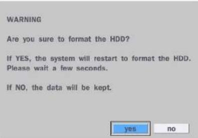
| DISK FORMAT | You will have an option of YES or NO for formatting the Hard Drive. After formatting HDD, the DVR will reboot. | ||
 | Caution: It is recommended to archive any data that you may need in the future before formatting the hard drive. | ||
 | |||
| DISK INFO | Hard drive information. Displays the following information; | ||
| HDD Size : 1740 GB (Free : 722 GB)HDD Last Time : 05/25/2016 17:22:00 | |||
| Model Name | Temperature Health(Good/Normal/Bad) | ||
| HDD 1 | WDC WD20PURX-64P6ZY0 | 39 °C (102 °F) Good | |
| HDD 2 | |||
| Model Name | Temperature | Health(Good/Normal/Bad) | |
| HDD 1 | WDC WD20PURX-64P6ZY0 | 39 °C (102 °F) | Good |
| HDD 2 |
4-9. Setup - CONFIG Mode
In the SETUP menu, select the CONFIG tab. Then, the configuration menu is displayed as pictured below.
Navigate through the menu items or change the settings using the mouse or the remote control.
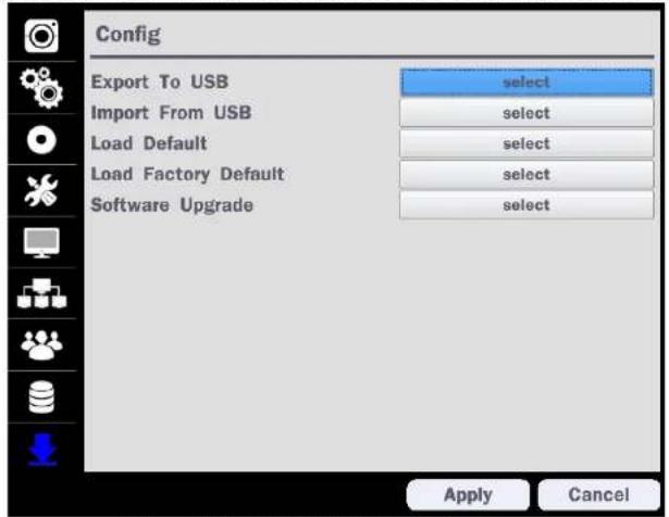
Figure 4.9.1. CONFIGURATION Setup Screen
Table 4.9.1. CONFIGURATION Setup
| Item Description | |
| EXPORT TO USB | User can save the current configuration (Setting values) of the DVR to the USB flash drive. Plug in the USB flash on the front panel and press the button to start the saving process. |
4-9-1. Firmware Upgrade
- Create a new folder named "upgrade" in the USB flash drive root directory.
- Create sub-folder for each model under "upgrade" folder and copy each firmware.
- For D16HUModels:
- Folder name - "d16hu
- File name - "main_D16HUspeco_.*.*_201****".bin
- For D8HU Models:
Folder name - "d8hu
- File name - "main_D8HUspeco_.*.*._201****".bin
- Plug in the USB flash drive on the rear panel.
- Navigate to CONFIG menu of SETUP.
- Select SOFTWARE UPGRADE.
- Follow the procedure from Figure 4.9.2 to Figure 4.9.4.

Figure 4.9.2
Figure 4.9.3

5. Live, Search and Playback
5-1. Live View
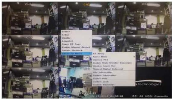
In the Live screen, video inputs from the cameras are displayed as they are configured in the Display Setup screen. When the mouse is right clicked, and the quick operation window will be displayed as below.
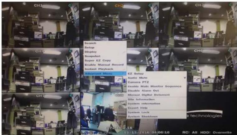
Figure 5.1.1. Live Screen and Quick Operation Window
On the bottom of the screen, various On-Screen Display (OSD) symbols, which indicate the status of the DVR, are described in Table 5.1.1.

2009/04/14 17:23:40
Indicates that sequencing mode is enabled.
Displays the current date and time.
RC: ALL Remote control ID display. If a remote ID is not set, the message "ALL" is displayed.

15% When Overwrite is not enabled, this displays the percent of the hard disk usage from 0-99%.
When Overwrite is enabled, the Bar will indicate with Overwrite

Continuous recording in progress.

Manual recording in progress. To set the Manual recording mode, press the Record button on the front panel.

Motion alarm recording in progress.

Sensor recording in progress.
Table 5.1.2. Menu Items in Quick Operation Window
| Icon Description | |
| Search Select this option to enter the Search menu. | |
| Setup Select this option to enter the Setup menu. | |
| Display | Display layout. Select between different multi-view display formats.D8HU: 1x1, 2x2, 3x3; D16HU: 1x1, 2x2, 3x3, 4x4 |
| Aspect Ratio Select 'Auto Stretch' or 'Pass Through' | |
| Snapshot | Click this option to create a snapshot of selected channel image. |
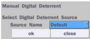
Digital Deterrent "Right now it just says "use".
Site Information
Press the button to view the record setting of a selected channel.
System Information
Press the button to view the system information.
Export Help Displays window with instructions for exporting video.
System Lock Locks the DVR from user access.
System Shutdown Click this button to shutdown system.
5-1-1. PTZ Control
Table 5.1.3. Menu Items in PTZ Control Window
| AUTOSCAN | Press the right key(▶) to start auto scan. Press the left key (◀) to stop auto scan. | |
| PRESET | Select PRESET, then press the left key(◀). A number input window will appear. Set the number (3digits) using the number key, then press the SEL to confirm the preset number for the current position. Press the right key (▶) and enter the number (3digits) to go to the preset position. | |
| TOUR | Select TOU and press the right (▶) key. A number input window will open. Select a number (1digit) using a number key, then press SEL to start the tour. Press the left (◀) key to stop the tour.Preset the number of the tour group in the OSD menu. | |
| NUMBER | For the TOUR and PRESET menu. | |
| Press ESC to return to the main menu |
5-2. Digital Zoom in Live and Playback Screen
HU series supports Digital Zoom feature during live and playback mode.
- Double click the target channel.

5-3. Search Screen
To enter the search screen menu, select Search menu on the screen using the mouse or press Search icon on live screen.
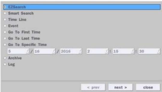
Figure 5.3.1. Search Screen
There are 7 options in the Search Menu, they are: EZSearch, Smart Search, Time Line (Calendar), Event, Go To First Time, Go To Last Time, Go To Specific Time, Archive list, and Log list on the screen.
5-3-1. EZSearch
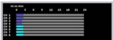
The EZSearch window is used to find stored video with ease using the thumb nail playback screen.
| Sun | Mon | Tue | Wed | Thu | Fri | Sat |
| 1 | 2 | 3 | 4 | 5 | 6 | |
| 7 | 8 | 9 | 10 | 11 | 12 | 13 |
| 14 | 15 | 16 | 17 | 18 | 19 | 20 |
| 21 | 22 | 23 | 24 | 25 | 26 | 27 |
bar
| Category | Value | |---|---| | CH 1 | 3 | | CH 2 | 3 | | CH 3 | 3 | | CH 4 | 3 | | CH 5 | 3 | | CH 6 | 3 | | CH 7 | 3 | | CH 8 | 3 |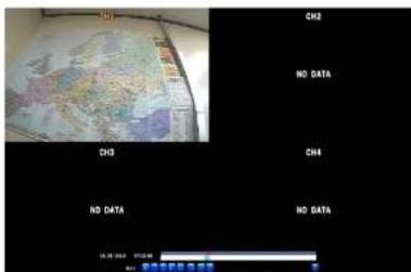
Figure 5.3.4. Second Thumbnail Screen
When the EZSearch menu is selected, a calendar is displayed that highlights dates with recorded data.
- Select a specific date on the calendar.
- Select a channel from Channel Selection Screen.
Then the Thumbnail Search screen displays 24 thumbnails, one for each hour of the day.
- Second step shows every 2 minutes and 30 seconds screen.
- Playback the selected image.
5-3-2. Smart Search
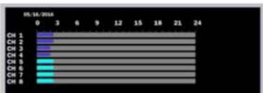
Smart Search is search the selected area quickly. User can search need to know area.
| Sun | Mon | Tue | Wed | Thu | Fri | Sat |
| 1 | 2 | 3 | 4 | 5 | 6 | |
| 7 | 8 | 9 | 10 | 11 | 12 | 13 |
| 14 | 15 | 16 | 17 | 18 | 19 | 20 |
| 21 | 22 | 23 | 24 | 25 | 26 | 27 |
bar
| Category | Value | |---|---| | CH 1 | 0 | | CH 2 | 3 | | CH 3 | 6 | | CH 4 | 9 | | CH 5 | 12 | | CH 6 | 15 | | CH 7 | 18 | | CH 8 | 21 | | (Last row) | 24 |
1) Select the start time and End time that user want to search
2) Set Zone as 'Partial' or 'Full'
3) Partial zone can select the area that user want.


| No. | Date |
| 111 | 08/31/2016 10:07:01 |
| 112 | 08/31/2016 10:07:02 |
| 113 | 08/31/2016 10:07:03 |
| 114 | 08/31/2016 10:07:04 |
| 115 | 08/31/2016 10:07:06 |
| 116 | 08/31/2016 10:07:07 |
| 117 | 08/31/2016 10:07:08 |
| 118 | 08/31/2016 10:07:09 |
| 119 | 08/31/2016 10:07:10 |
| 120 | 08/31/2016 10:07:11 |
| 121 | 08/31/2016 10:07:13 |
| 122 | 08/31/2016 10:07:14 |
| 123 | 08/31/2016 10:07:15 |
| 124 | 08/31/2016 10:07:16 |
| 125 | 08/31/2016 10:07:17 |
| 126 | 08/31/2016 10:07:22 |
| 127 | 08/31/2016 10:07:23 |
| 128 | 08/31/2016 10:07:24 |
| 129 | 08/31/2016 10:07:25 |
| 130 | 08/31/2016 10:07:26 |
| 131 | 08/31/2016 10:07:27 |
| 132 | 08/31/2016 1:07:28 |
| 133 | 08/31/2016 10:07:29 |
| 134 | 08/31/2016 10:07:31 |
7) Click the list that user want to playback.

| No. | Date |
| 111 | 06/31/2016 10:07:01 |
| 112 | 06/31/2016 10:07:02 |
| 113 | 06/31/2016 10:07:03 |
| 114 | 06/31/2016 10:07:04 |
| 115 | 06/31/2016 10:07:06 |
| 116 | 06/31/2016 10:07:07 |
| 117 | 06/31/2016 10:07:08 |
| 118 | 06/31/2016 10:07:09 |
| 119 | 06/31/2016 10:07:10 |
| 120 | 06/31/2016 10:07:11 |
| 121 | 06/31/2016 10:07:13 |
| 122 | 06/31/2016 10:07:14 |
| 123 | 06/31/2016 10:07:15 |
| 124 | 06/31/2016 10:07:16 |
| 125 | 06/31/2016 10:07:17 |
| 126 | 06/31/2016 10:07:22 |
| 127 | 06/31/2016 10:07:23 |

Figure 5.3.7. Calendar Screen

Figure 5.3.8. Time-Line Search Screen
When the Timeline menu is selected, the user can see a calendar, which displays recorded dates with highlights. Select a specific date and time. Click and drag the red time indicator bar to the desired hour. User can select a specific minutes using a button in the above red box. Press the "play" button after selecting the specific time. Press the "prev" to return to the Search window.
5-3-4. Event Search
The Event Search window is used to find stored video.


Figure 5.3.10. Event Search Screen
5-3-5. Go To First Time
You can access the oldest recorded data on the DVR hard drive by selecting Go To First Time on the Search window. Press the "prev" to return to the Search window.
5-3-6. Go To Last Time
You can access the latest recorded data on the DVR hard drive by selecting Go To Last Time on the Search window. Press the "prev" to return to the Search window.
5-3-7. Go To Specific Time
User can search for video data from a specific instance by setting the date and time in the GO SPECIFIC TIME menu. Use the mouse or the remote control to change the date and time value and press the PLAY button after setting. If there is no video data in the set date and time, No Data Exist message displays.
5-3-8. Archive List
The ARCHIVE Search window is used to find previously stored video or images.


5-3-9. Log List
You can access the LOG list search screen by selecting LOG on the SEARCH window.
![Log Date NTP : Keep(earlier than system time) 08/31/2016 04:00:00 System Start : [25] Software Upgrade 08/31/2016 13:58:33 Video In : CH1 08/31/2016 13:58:34 Video In : CH2 08/31/2016 13:58:34 Video In : CH3 08/31/2016 13:58:34 Video In : CH4 08/31/2016 13:58:34 NTP : Keep(earlier than system time) 08/31/2016 13:59:00 7 log(s) found backup < prev next > close](/content/2026/06/1216667/images/c89d982ee680e8ed97b97d0ebf54ec00f3372b50a65f080c1f0d4f025d00a62c.jpg)
Figure 5.3.12. Log List Screen
When the Log menu is selected, the user can see a calendar, which has a log data. Select a specific date and press NEXT button, and then the log data will be displayed. Press the SAVE button to save the data and then the data is saved as a text file format.
5-4. Play Mode
During playback of a recorded event, the mode changes from SEARCH to PLAY. While in PLAY mode, you may return to the SEARCH screen by pressing the X button on the status bar.

natural_image
Interior ceiling view with recessed lighting and ventilation grilles (no text or symbols visible)


Jump/Step backward. The playback position moves 60 seconds backward.
Press to play or pause recorded video.
Jump/Step forward. Playback position moves 60 seconds forward.
• 2x, 4x, 8x, 16x for D8HU
- 2x, 4x, 8x for D16HU
Single Channel forward playback speed 1x, 2x, 4x, 8x, 16x, 32x, 64x
Slow Mode play. Forward playback speed x1/4, x1/2
Press to back up the video. User can select archive file formats (Still image, NSF, AVI and EXE).
EZCopy button. User can copy video data as NSF, AVI and EXE format.
Return to the previous menu screen, search window, or exit from the Menu.
6. Export and Back Up
6-1. Still Image Backup onto USB Flash Drive
Still images can be captured and archived onto a USB flash drive or an USB external hard drive in live mode or while playing back recorded video.
- Select a specific channel, which wants to back up on live screen.
- When you press "Snapshot" button on Quick operation window, the media selection window screen will display.

- Once you press "start" button, the system will capture a still image and archive onto a USB flash drive.

NOTICE
USB Flash Drive must be in FAT32 file format.
6-2. Video Backup onto USB Flash Drive during playback
Video can be captured and archived onto the USB flash drive or a hard drive while playing back the
recorded video. In playback mode, press the "Export" button to launch the backup function.
- When you press "Export" button on the selected channel or all channels, the DVR will ask whether to archive a Still Image, NSF, AVI or EXE and select the proper media type.


- Select USB Drive (Flash Drive) to back up less than an hour. Select USB HDD (Large Backup) to back up from 1 hour to 24 hours. (Only for NSF type)

- Once you select the channel and duration, the system will start to archive the data to the USB drive.

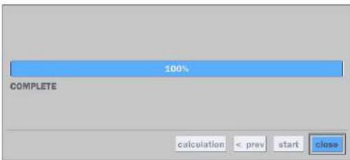
- The following shows the image to complete the backup. Select lose to return to the previous screen.
6-3. EZCopy: Video Backup onto USB Flash Drive during playback
Using EZCopy feature, Video can be easily archived onto the USB flash drive or a hard drive.
In playback mode, press the "EZ Copy" button to launch the backup function.
- Press "EZCopy" button on the selected channel or all channels.

- Then, EZCopy START time will display.

- EZCopy window will display. The DVR will ask whether to archive a NSF, AVI or EXE.

- After backup format is selected, also select media type and channel(s) to archive the data to the media.
6-4. Transferring Still Images or Video from the ARCHIVE List
The stored data in the hard drive can be found in the ARCHIVE list in the SEARCH window.
User can back up still images or video into the storage device from the ARCHIVE list.
- Select the date to begin searching and navigate through the days using the mouse or the remote control.
- Once you have selected the date, press the NEXT button to open the list of stored data.
- Use the mouse or the remote control to scroll through the archive list.
- Select a list of stored events in the archive list.
- Once the desired event has been selected, press the DISPLAY button to view the still image or the first frame of the selected video.
6-5. Playback of Backup Video
6-5-1. AVI Format
AVI format: AVI format video can be played back by Window Media Player™ or other media player that is compatible with AVI format video.
- Please install the Decoder Filter that the DVR copies "DvrPlayer" folder on USB flash drive with the video. Decoder Filter is exported to the "/DvrPlayer" folder of the USB drive.
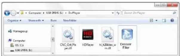
- Otherwise, the video and time stamp over video can't be properly played back and won't be displayed on Window Media Player™.
natural_image
Interior view of a museum or exhibition hall with wooden flooring, display cases, and ceiling lighting (no visible text or signage)
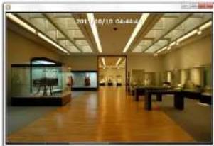
Timestamp On AVI. The subtitle is embedded to the video clip file.
The subtitle is embedded to the AVI file. To display a subtitle, user should install a special filter called "Decoder Filter".
6-5-2. NSF Format
7. Network Access Using the Multi-Sites Network Viewer
7-1. Overview
The SpecoTech Multi Client is a multiple site monitoring client software with video, audio, and alarm signals from the DVRs over the network. The SpecoTech Multi Client does not limit the number of DVR units to register.
The program displays up to 16 DVRs and supports dual monitors.
On the program, user may control PTZ cameras on the DVRs. By attaching a microphone and speaker system to devices on site, the user may make bi-directional audio communication over the network.
7-2. PC Requirements
Minimum PC Requirements
| CPU Intel Core | 3 |
| 1.8Ghz | |
| Memory 2GB DDR2 | |
| VGA 512MB | |
| Resolution 1280x720 | |
| Disk Space 1GB | |
| OS | Windows 2000, XP Professional, XP Home, Vista, 7 (NOTE: Not all versions of Vista and 7 are supported) |
| Network | 10/100Base T |
| Others | Direct X 9.0c or Higher |
Recommended PC Requirements
| CPU Intel Core i5 |
| 2Ghz or higher. |
7-3. Installation of the Program
- Insert the provided CD in the CD drive and double-click "SpecoTech Multi Client (XXXX).exe"
- Select a destination folder and click "Next".

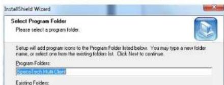
- Select the program folder and click "Next".
7-4. Live Window
When installation is completed, double click the "SpecoTech Multi Client" icon on your desktop to start the program.
7-4-1. Main User Interface
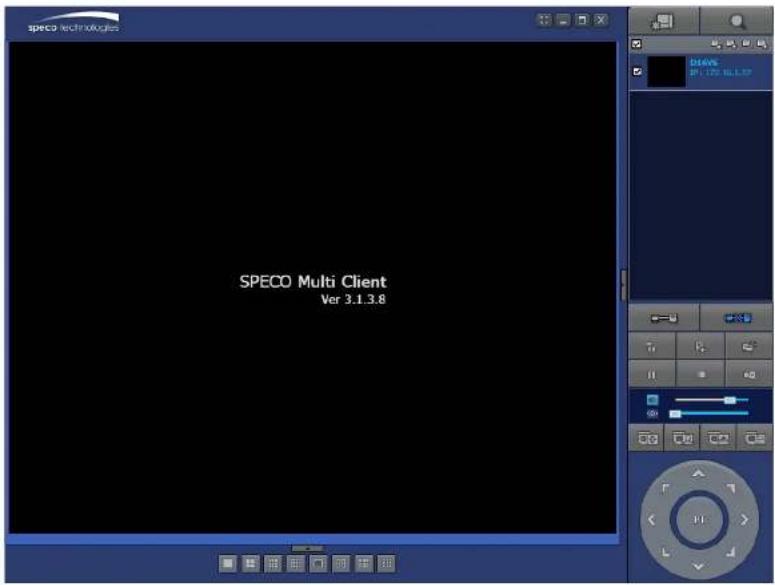
7-4-2. Control Buttons
| Button Description | ||
 | LOCAL PLAYBACK | Click this icon to run a playback window to search and play videos that are recorded in the local PC. |
 | REMOTE PLAYBACK | Click this icon to run a playback window to search and play videos that are recorded in the remote DVR. |
 SITE MANAGEMENT SITE MANAGEMENT | THUMBNAIL REFRESH: Click this icon to refresh and renew thumbnail image of the connected sites.SITE ADDITION: Click this icon to open 'Site Addition' window.SITE DELETE: Click this icon to delete site from the index window, after disconnect a site.NET FINDER: Select the site from the index window and click this icon to modify the information of specific site. | |
 | CONNECT | Click this icon to connect the selected site/sites. |
 | DISCONNECT | Click this icon to disconnect the selected site/sites. |
 | SETUP | Click this icon to setup configuration of SpecoTech Multi Client. |
 | CAPTURE | Click this icon to capture a still image. |
 | EVENT LIST | Opens list of events logged by the SpecoTech Multi Client. |
 | PAUSE | Click this icon to play/pause live video. |
7-5. Search and Playback Window
7-5-1. Main User Interface
You can access to search window by clicking the search icon (Local Playback / Remote Playback) on the upper right of the Live Window.
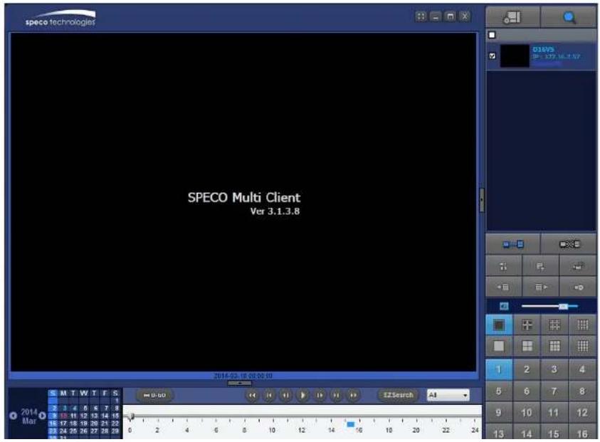
7-5-2. Main Control Panel
| Button Description | |
 LOCAL PLAYBACK LOCAL PLAYBACK | Click this icon to run a playback window to search and play videos that are recorded in the local PC. |
 REMOTE PLAYBACK REMOTE PLAYBACK | Click this icon to run a playback window to search and play videos that are recorded in the remote DVR. |
 | Display the site information and the connection status. |
 CONNECT CONNECT | Click this icon to connect the selected site/sites. |
 DISCONNECT DISCONNECT | Click this icon to disconnect the selected site/sites. |
 SETUP SETUP | Click this icon to setup configuration of SpecoTech Multi Client. |
 CAPTURE CAPTURE | Click this icon to capture a still image. |
 EVENT LIST EVENT LIST | Opens list of events logged by the SpecoTech Multi Client. |
 EZCopy Start EZCopy Start | Click this icon to set the beginning time for backup of the recorded video in AVI format. |
 EZCopy End EZCopy End | Click this icon to set the ending time for backup of the recorded video in AVI format. |
 | Click this icon to back up the recorded video in AVI format. |
  | To change a timeline scale from 24 hours to 60 minutes.The timeline shows recorded data in color on the bar. You can adjust the timeline scale and move it to the time you wish to playback. Then click the play icon to display the recorded video. |
 | Playback buttons. |
 | EZSEARCH: Thumbnail search over the network.- Shows 24 thumbnail images, one for each hour from 00:00 to 23:00.- Each hour is further broken up 24 segments; each is 150sec.- Then select the tile to play* Click the "PREVIOUS" button to go the previous step. |
 | Digital Zoom Window in Live and Playback. (Only available in Single Channel Viewing) |
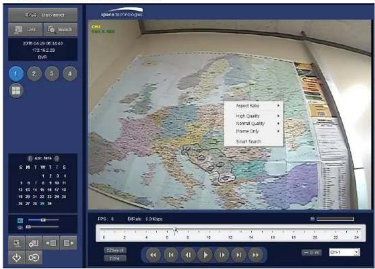
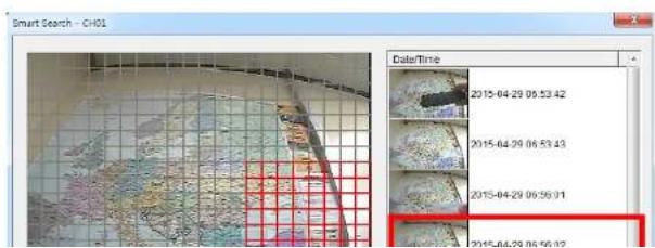
7-5-3. SMART SEARCH
1) User can search with selected area
2) Click right mouse button when playback
| Aspect Ratio | ▶ | |
| High Quality | ▶ | |
| Normal Quality | ▶ |

7-6. Setup of SpecoTech Multi Client
Click the setup icon

window is displayed as below.
7-6-1. General
Security Option: Set a password for security options. Select security options and set a password.
Then when you access any of selected functions, you need to enter the password.
You can also set the save path for capturing and backup.
Save Path: Specify the location to save captured still image for Capture and Backup data.
Miscellaneous
Automatic Reconnection: If enabled, the software will automatically try to reconnect to the last successful IP address. But, when CLIENT ACCESS is OFF on the DVR, the software will not try to reconnect even if it is enabled.
Always On Top: If enabled, the software display will be continuously on the top of other windows.
Time Format: Change the way the Client software displays the time.

7-6-2. Event
Event log can be archived and searched.
Event Log: Specify the location to save event logs and select event to archive.
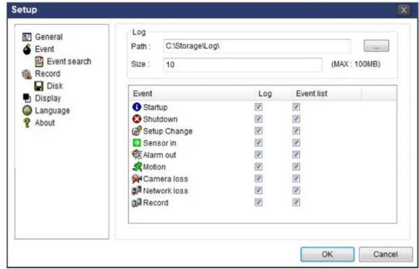
Event Search: Event log can be searched from the selected time.

7-6-3. Record
Record Setup: You can set the recording conditions as the following; Always, Event, or Auto record. And you can also select target DVR/DVRs and channel/channels. When you set the recording condition to event, you can set event for motion or alarm with duration.
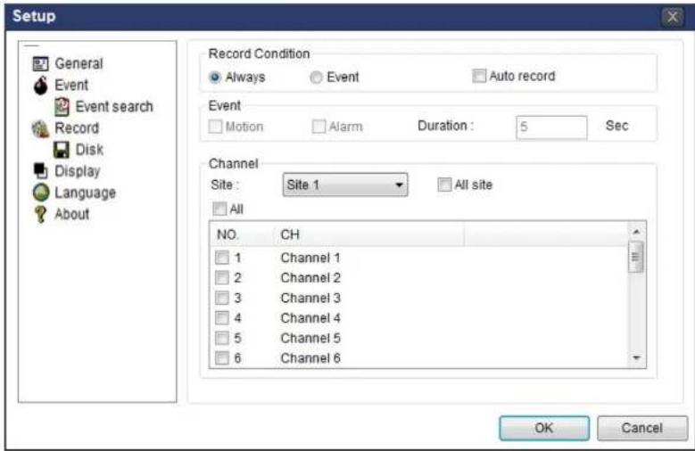
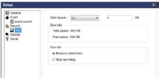
Record Local Storage Setup: You can select the local disk to record and the amount of disk space you want to allow the program to use for recording. You can also select the option to overwrite data or stop recording when the maximum amount of disk space is full.

7-6-4. Display
You can select the OSD (On Screen Display) to be displayed.

7-6-5. Language
English, French and Spanish is selectable.

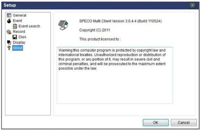
7-6-6. About
"About" provides network client version information.
7-7. Remote Setup
The menu settings for the DVR unit can be set over network.
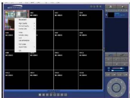
Put the cursor of the mouse on the channel, which is connected to the site and right click on the mouse to open the submenu. Then the following window is displayed as below. Select the REMOTE SETUP.

Then the setup window is displayed. The specified menu screen is displayed on the upper left of the screen.
Enter the password of the DVR when prompted. (NOTE: The password is same with DVR setup password.)
Setting is the same as with the DVR menu setting. Refer to the corresponding pages for details on the setting items.

7-7-1. System
Select System to set system and time settings.
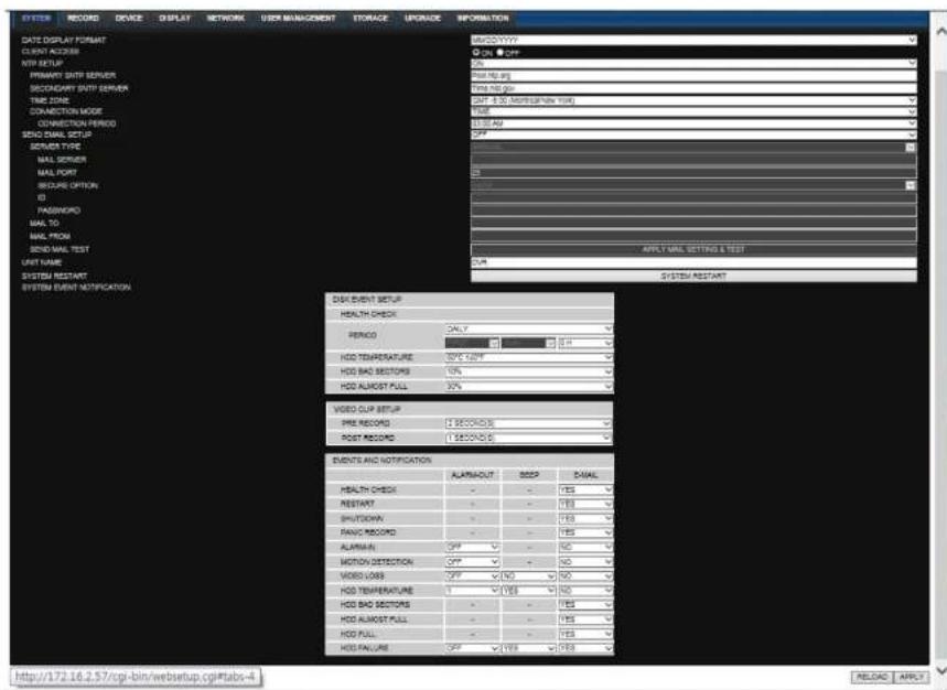
• DATE DISPLAY FORMAT: Select the date display format.
- CLIENT ACCESS: Enable/Disable remote access through network client software.
o SEND MAIL TEST: Examine the function with registered information.
- USER NAME: Name the DVR
- SYSTEM RESTART
• SYSTEM EVENT NOTIFICATION
Allows the user to set EVENT NOFICIATION ON or OFF
- HEALTH CHECK
(Allows the user to set MAIL STATUS periodically) : DAILY or WEELY or MONTHLY
○ HDD TEMPERATURE
- HDD BAD SECTOR
- HDD ALMOST FULL
o VIDEO CLIP SETUP: Setting the duration for pre and post recording.
- EVENTS AND NOTIFICATION
- HEALTH CHECK / RESTART / SHUTDOWN / PANIC RECORD
Enable Email Notification in the event a problem occurs with the HU.
- ALARM-IN : Enable Email Notification when the camera detects sensor
- MOTION DETECTION : Enable Email Notification when the camera detects motion
o VIDEO LOSS: Enable Email, Beep and Alarm output Notification when the camera signal is lost.
o HDD TEMPERATURE : Enable Email Beep and Alarm output Notification when the HDD reaches the maximum temperature - HDD BAD SECTOR: Enable Email Notification when the HDD has bad sectors.
- HDD ALMOST FULL: Enable Email Notification when the HDD is almost full.
o HDD FULL: Enable Email Notification when the HDD is full. - HDD FAILURE: Enable Email, Beep and Alarm output Notification when the HDD fails.
7-7-2. Record
Select RECORD tab to set the recording conditions.

These settings apply to the specified channel only.
- Recording Setup
o RESOLUTION: Sets the resolution for the recordings. The value applies to an individual channel.
o FRAME RATE: Sets the recording rate.
o QUALITY: Sets the image quality in 5 levels.
o RECORDING: Sets the recording mode.
o RECORDING MODE: CONTINUOUS. SCHEDULE. MOTION. SENSOR
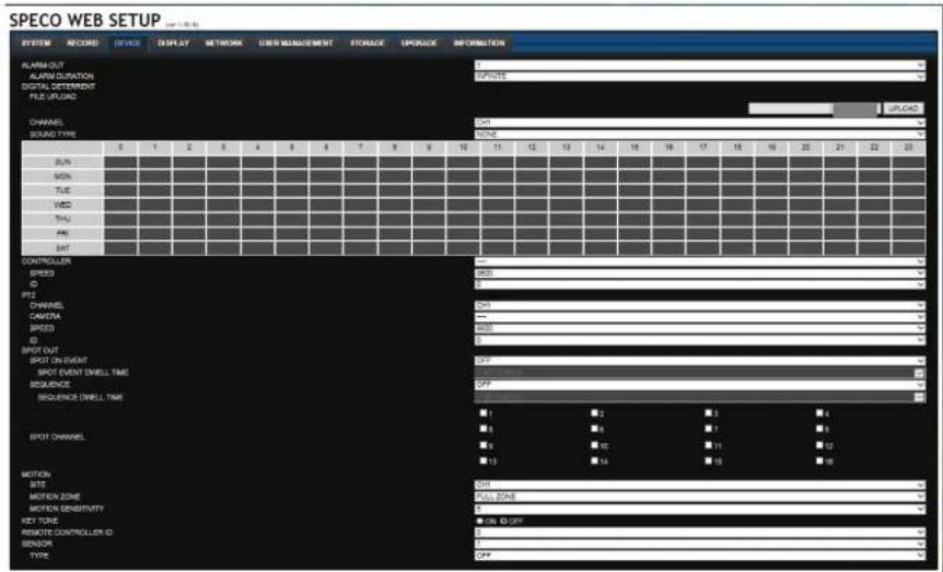
7-7-3. Device
Select Device to set Spot Out, Enable/Disable CVBS Out, motion zone.
RELOAD APPLY
• ALARM OUT: Set the alarm out duration.
- DIGITAL DETERRENT: Set the schedule of digital deterrent function and upload the sound file to DVR.
• CONTROLLER: Set the controller baud rate and ID.
• PTZ: Set the PTZ baud rate. protocol. and ID.
7-7-4. Display
Select the DISPLAY tab to set the DISPLAY conditions.

These settings apply to all channels.
- OSD: Sets whether to display or not, the date and time as well as channel number on the screen.
- OSD CONTRAST: Adjust the character contrast on the screen.
• MAIN MONITOR SEQUENCE: Setting for automatically switching the displayed video.
SEQUENCE DWELL TIME: Sets the interval for automatically switching the screens.
• SITE: Name, Covert, Brightness, Contrast, Hue, Saturation
These settings apply to the specified channel only.
7-7-5. Network
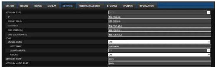
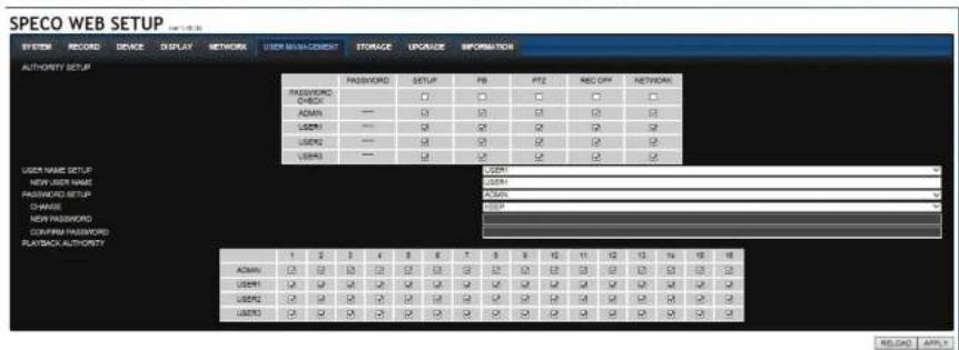
7-7-6. User Management
Select the USER MANAGEMENT tab to set the DISPLAY conditions.
7-7-7. Storage
Select Storage to configure continued recording settings by overwriting the hard disk and the storage period for the recording data.

• OVERWRITE: Continues recording by writing over previous recordings when HDD is full.
- DISK INFO: Shows the information of HDD installed in DVR
7-8. Operation
7-8-1. Addition, Delete, and Modify of DVR Sites
7-8-1-1. Addition of Sites
- Click SITE ADDITION button. And then the following window will be displayed as below.
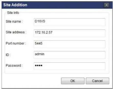
Site Name: Input a name that properly describes a site.
IP Address: Input IP address (Public IP address of a router that DVR is connected.) or Domain name
- Port Number: Default Port Number is "5445".
ID: Input ID of DVR. Default ID is "admin".
- Password: Input network password of DVR that is same with DVR setup password.
- Click OK button. And then the registered site is added on the directory window.
7-8-1-3. Modify of Sites
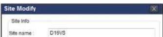
- Select the site/sites to modify from the directory window.

- Click NET FINDER button. And then the following window will be displayed as below.

- Click MODIFY button. And then the modified information is displayed as below.
7-8-2. Connect and Disconnect
7-8-2-1. Connect
- Select site/sites to connect from the directory window.
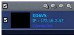
- Click CONNECT button, and then site/sites displays/display as connected.
7-8-2-2. Disconnect
- Select site/sites to disconnect from the directory window.
7-8-3. Still-image Capture During Live
- Double-click a channel to capture from the display screen. (Otherwise all channels will be captured.).
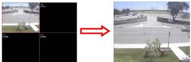
natural_image
Side-by-side comparison of a road scene before and after transformation, showing original and rotated views with no visible text or symbols.- Click CAPTURE button. And then a Capture window will be displayed as below.
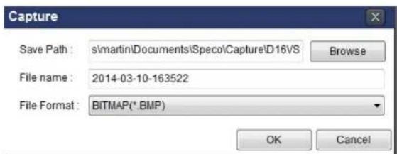
- Set Save Path, File Name, and File Format. And then click OK button.
- Still image is saved as set in Capture window.

7-8-4. Recording Video on Local PC During Live
- Click SETUP button. And then a setup window will be displayed as below.
- Select Record and set the values.

- Select Disk and set the values.
7-8-5. Local Playback and Remote Playback
7-8-5-1. Playback of Recorded Video on a Local PC
- Click LOCAL PLAYBACK. And then Playback Window will be displayed over the Live
Window.

-
Select site/sites to connect from the directory window.
-
Click CONNECT button. And then Green bar displays on Search calendar and timeline scale window.

- Move the marker on the timeline scale to where there is video data and press the PLAY button.
7-8-5-2. Playback of Recorded Video on Remote DVR
- Click REMOTE PLAYBACK. And then Playback Window will be displayed.
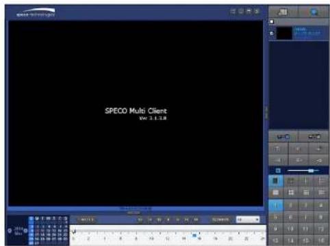
-
Select the site to connect from the directory window.
-
Click CONNECT. And then Green bar displays on Search calendar and timeline scale.

- Move the marker on the timeline scale to where there is video data and press the PLAY button.
7-8-6. AVI Backup during Playback
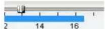
You can back up the recorded videos in AVI format during playback.
- Double-click the target channel to backup.
- Select the beginning time by using the search calendar and timeline scale bar.

- Click EZCOPY START button on the timeline scale to select the beginning point of the backup.

- Click EZCOPY END button on the timeline scale to select the ending point of the backup. Then, the selected starting point and the ending point on the timeline scale bar will be marked in green.

- Click BACKUP. And then the BACKUP window will be displayed as below.


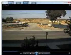
- AVI video data is recorded as selected in AVI Backup window. AVI format video can be played back by using Window Media Player™ or other media player that is compatible with AVI format video.
natural_image
Exterior view of a rural road with buildings and trees, no visible text or symbols8. Network Access Using the Web-Browser Viewer
The DVR provides a live remote monitoring feature by web-browser viewer. (NOTE: Web-Browser is only available for Internet Explorer)
- Check the IP address of the DVR from SETUP>SYSTEM>DESCRIPTION>IP ADDRESS or
- Input the IP address or Domain name address that you pre-registered.

- Click this bar. Then the dialog box is displayed.

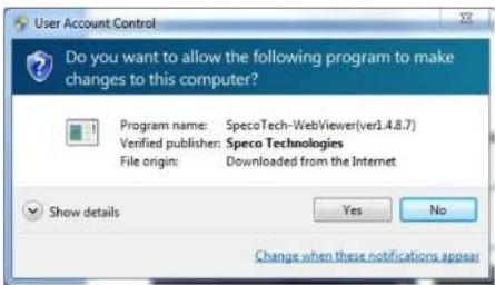
- Click "Install" to download and install the ActiveX control.
- The Web Browser Viewer will be displayed as below after the ActiveX installation

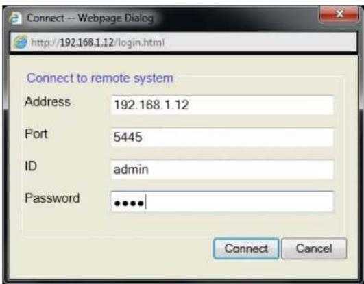
- Site Name: Input a name that properly describes a site.
-
IP Address: Input IP address (Public IP address of a router that DVR is connected.) or Domain name
• Port Number: Default Port Number is "5445".
• ID: Input ID of DVR. Default ID is "admin". -
Password: Input network password of DVR that is same with DVR setup password.
- Then the cameras connected to the DVR are displayed on the screen.
- Use mouse scroll to digitally zoom in and out from a single channel display.

9. Network Access Using the Smart Phone Viewer

Notice
Data Usage applied without Wi-Fi connection. Please check with your Phone Carrier.
9-1. App Viewer for iPhone
- Enter the Apple App Store.


- Search "Speco Player" in the App Store.

Notice
SPECO Player is for the HU, VX, VT, HT, HS, ZS, NS, DS, RS, WRS and HD series DVRs. SPECO VIEWER is not compatible with the T Series DVR's (TH, TN or TL) or
9-1-1. Live
- Open the installed "Speco Player" App and click action to add a remote device.
- Enter the site name, IP or DDNS address, Network Port number (default 5445), ID(default admin) and Password that is same with DVR setup password. Then, click "Save" button.
| About | Device List | + |
| Demo DS | > | |
| Demo HS | > | |
| Demo NSP | > |

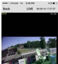
- The app will display the selected channel(s). Double tap the channel screen to switch 1 channel display to 4, 8, 10, 16 channels split display depending on the DVR.

- To select the display mode(1, 4, 9, 10 or 16 split display), tap the arrow menus button
natural_image
Outdoor scene with a large building and outdoor furniture, no visible text or symbols9-1-2.PTZ Control
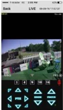
To control the PTZ functions of the camera, tap the menu button. Then PTZ menu icons will display. Using the PTZ icon on the screen, can control PTZF functions.
9-1-3. Playback
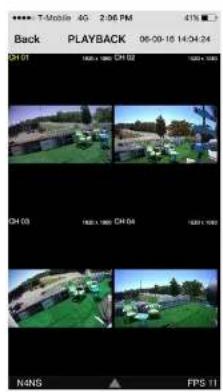
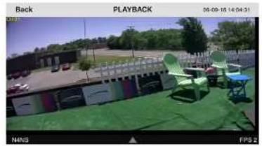
- Select mode as 'Playback' 📄 and click 'Connect' button. Then select Date & Time and click 'Connect' button.

→
natural_image
Outdoor scene with green chairs and a building, no visible text or symbols- Tap the menu button. Then Playback menu icons will display.

9-2. App Viewer for Android Phone
- Enter the Android Play Store.
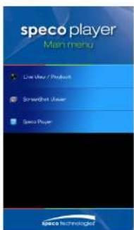
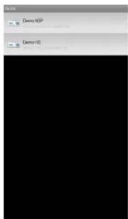
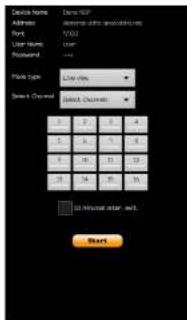
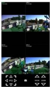
- The app will display the selected channel(s). Double tap the channel screen to switch 1 channel display to 4 channels split display.
natural_image
Four-panel collage showing outdoor scenes with buildings, greenery, and a bridge under different lighting or sky conditions (no visible text or symbols)- The app will display the selected channel(s). Double tap the channel screen to switch 1 channel display to 4 channels split display.
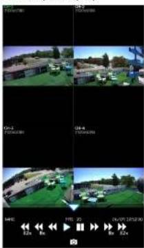
9-2-3.PTZ Control
To control the PTZ function of the camera, tap the channel screen, and then the channel name will be highlighted in Light Green. Using the PTZ menu icons on the screen, control PTZF.

natural_image
Two-panel image showing a 3D-rendered building with green roof and adjacent garden, alongside a person in a blue shirt (no visible text or symbols)APPENDIX: Network Connection - LAN
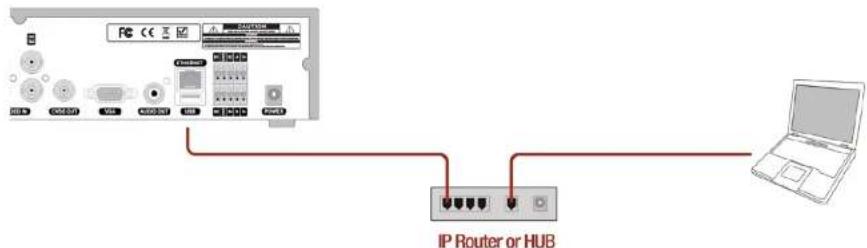
- Install the network client software from the supplied CD.
- Check the IP address from SETUP > SYSTEM > DESCRIPTION or SETUP > NETWORK of DVR.
| Model Name | D16HU |
| Software Version | Ver 5.5.7BN_20180406 |
| Storage Size | 435 GB |
| IP Address | 172.16.200.146 |
| MAC Address | 00:02:69:FF:F7:20 |
| DDNS Status | Ready - d16hu_fff720 |
- Run the network client software.


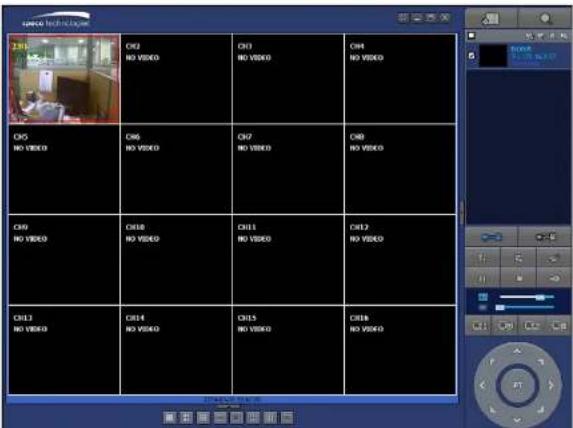
APPENDIX: Network Connection – Internet and DDNS
Dynamic Domain Name System (DDNS) allows a domain name to be constantly synchronized with a dynamic IP address. A current dynamic IP address is being associated with a static domain name.
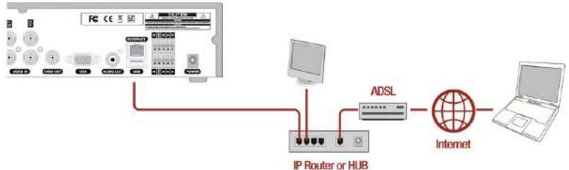
flowchart
graph TD
    A["PC"] -->|USB| B["Internet"]
    B --> C["ADSL"]
    C --> D["IP Router or HUB"]
    D --> E["Laptop"]
- Go to SETUP>NETWORK>DDNS and set the DDNS SERVER to ON.

If you set ezDDNS to ON, the host name is automatically generated and registered.
-
Go to SETUP>NETWORK>DDNS>HOST NAME. Manually enter a domain name using the virtual
-
When DDNS setting is done, click the APPLY button. Otherwise DDNS setting will not be applied.
- When you exit SETUP menu, DDNS NOTIFY window will pop up.
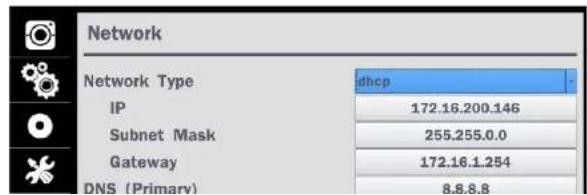
- DDNS registration status can be checked from SYSTEM INFORMATION or SETUP>SYSTEM>DESCRIPTION>DDNS STATUS

- Check the NETWORK PORT (Default: 5445), WEB PORT (Default: 80), and the IP Address of the DVR from SETUP>NETWORK.
- Run the network client software.
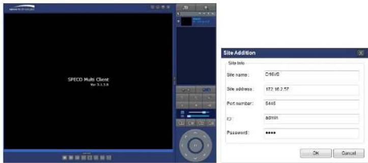
-
Input Site Name, Site Address (IP address), Port No., and Password on the connect window.
-
Site Name: Input a name that properly describes a site.
• IP Address: Domain name or Public IP address of a router that DVR is connected.
• Port Number: Default Port Number is "5445".
• ID: Input ID of DVR. Default ID is "admin". -
Password: Input network password of DVR that is same with DVR setup password.
-
And select the OK button. Then, press button after checking the left check box.

- Cautions
- Explanation of Graphical Symbols
- These precautions MUST be followed for safety reasons
- Warning
- Product Components
- Table of Contents
- Main Features
- Initial Boot-up Process
- 2-1. Initial Boot up and Basic Time Setup
- 2-2. Setting up Daylight Savings Time
- Select ON from the DAYLIGHT SAVING dropdown menu.
- 2-3. Setting NTP (Network Time Protocol)
- 2-4. EZ Setup
- EZ Network (Using an internet connection)
- 2-5. IP Camera SETUP (through SpecoTech Web Viewer)
- 2-6. Dual Streaming
- Front and Rear Panels
- 3-1. Front Panel
- 3-2. Rear Panel Connectors
- 3-3. Remote Control
- Setting up the DVR
- 4-0. Setup - Main Live Screen
- 4-1. Setup - IP CAMERA
- Address
- 4-1-1. Scan Menu
- 4-1-2. ONVIF Setup Menu
- SYSTEM
- 4-2. Setup - SYSTEM
- CONNECTION PERIOD
- 1-4) Set Video clip duration
- 2) How to playback
- 4-3. Setup - RECORD Mode
- 4-4. Setup - DEVICE Mode
- 4-4-1. Digital Deterrent
- SCHEDULE
- 4-4-2. Keyboard Controller & PTZ Setup
- 4-4-4. Motion Zone Setup
- 4-5. Setup - DISPLAY Mode
- 4-6. Setup - NETWORK Mode
- 4-6-1. Network Types
- 4-6-1-1. DHCP
- 4-6-1-2. STATIC
- NOTE
- 4-6-2. DDNS
- 4-6-3. Network Port and Web Port
- NOTE:
- Network access beyond a router
- 4-7. Setup - USER MANAGEMENT Mode
- AUTHORITY OF
- PLAYBACK
- REMOTE
- TIMEOUT
- IMPORT
- CERTIFICATATE
- FROM USB
- ADVANCED
- SETUP
- DEBUG PORT
- Network
- Connection
- 4-8. Setup - STORAGE Mode
- 4-9. Setup - CONFIG Mode
- 4-9-1. Firmware Upgrade
- Live, Search and Playback
- 5-1. Live View
- 5-1-1. PTZ Control
- 5-2. Digital Zoom in Live and Playback Screen
- 5-3. Search Screen
- 5-3-1. EZSearch
- 5-3-2. Smart Search
- 5-3-4. Event Search
- 5-3-5. Go To First Time
- 5-3-6. Go To Last Time
- 5-3-7. Go To Specific Time
- 5-3-8. Archive List
- 5-3-9. Log List
- 5-4. Play Mode
- Export and Back Up
- 6-1. Still Image Backup onto USB Flash Drive
- NOTICE
- 6-2. Video Backup onto USB Flash Drive during playback
- 6-3. EZCopy: Video Backup onto USB Flash Drive during playback
- 6-4. Transferring Still Images or Video from the ARCHIVE List
- 6-5. Playback of Backup Video
- 6-5-1. AVI Format
- 6-5-2. NSF Format
- Network Access Using the Multi-Sites Network Viewer
- 7-1. Overview
- 7-2. PC Requirements
- 7-3. Installation of the Program
- 7-4. Live Window
- 7-4-1. Main User Interface
- 7-5. Search and Playback Window
- 7-5-1. Main User Interface
- 7-5-3. SMART SEARCH
- 7-6. Setup of SpecoTech Multi Client
- 7-6-1. General
- Miscellaneous
- 7-6-2. Event
- 7-6-3. Record
- 7-6-4. Display
- 7-6-5. Language
- 7-6-6. About
- 7-7. Remote Setup
- 7-7-1. System
- 7-7-2. Record
- 7-7-3. Device
- 7-7-4. Display
- 7-7-5. Network
- 7-7-6. User Management
- 7-7-7. Storage
- 7-8. Operation
- 7-8-1. Addition, Delete, and Modify of DVR Sites
- 7-8-1-1. Addition of Sites
- 7-8-1-3. Modify of Sites
- 7-8-2. Connect and Disconnect
- 7-8-2-1. Connect
- 7-8-2-2. Disconnect
- 7-8-3. Still-image Capture During Live
- 7-8-4. Recording Video on Local PC During Live
- 7-8-5. Local Playback and Remote Playback
- 7-8-5-1. Playback of Recorded Video on a Local PC
- 7-8-5-2. Playback of Recorded Video on Remote DVR
- 7-8-6. AVI Backup during Playback
- Network Access Using the Web-Browser Viewer
- Network Access Using the Smart Phone Viewer
- 9-1. App Viewer for iPhone
- 9-1-1. Live
- 9-1-2.PTZ Control
- 9-1-3. Playback
- 9-2. App Viewer for Android Phone
- 9-2-3.PTZ Control
- APPENDIX: Network Connection - LAN
- APPENDIX: Network Connection – Internet and DDNS
Brand : Speco Technologies
Model : D8WHUM
Category : Surveillance Camera