ZIPL84B2 - Security Camera Speco Technologies - Free user manual and instructions
Find the device manual for free ZIPL84B2 Speco Technologies in PDF.

User questions about ZIPL84B2 Speco Technologies
0 question about this device. Answer the ones you know or ask your own.
Ask a new question about this device
Download the instructions for your Security Camera in PDF format for free! Find your manual ZIPL84B2 - Speco Technologies and take your electronic device back in hand. On this page are published all the documents necessary for the use of your device. ZIPL84B2 by Speco Technologies.
USER MANUAL ZIPL84B2 Speco Technologies
NRL (4 and 8 Channel)
User Manual
natural_image
Exterior view of a black wireless device labeled 'Speca Technologies' with control buttons and ports (no readable text beyond branding)
natural_image
Back panel of a network device showing ports, connectors, and a router (no visible text or symbols)Notes
- Please read this user manual carefully to ensure that you can use the device correctly and safely.
- There may be several technically incorrect places or printing errors in this manual. The updates will be added into the new version of this manual. The contents of this manual are subject to change without notice.
- This device should be operated only from the type of power source indicated on the marking label. The voltage of the power must be verified before using the same. Kindly remove the cables from the power source if the device is not to be used for a long period of time.
- Do not install this device near any heat sources such as radiators, heat registers, stoves or other devices that produce heat.
- Do not install this device near water. Clean only with a dry cloth.
- Do not block any ventilation openings and ensure proper ventilation around the machine.
- Do not power off the device at normal recording condition.
- This machine is for Indoor use only. Do not expose the machine in rain or moist environment. In case any solid or liquid get Inside the machine's case, please turn off the device immediately and get it checked by a qualified technician.
- Do not try to repair the device by yourself without technical aid or approval.
Contents
1 Introduction....1
1.1 Welcome! 1
1.2 Features.... 1
1.3 Front Panel Descriptions 3
1.4 Rear Panel Descriptions.... 3
1.5 Connections....3
2 Basic Operation Guide 4
2.1 Startup & Shutdown 4
2.1.1 Startup....4
2.1.2 Shutdown 4
2.2 Remote Control 4
2.3 Mouse Control....5
2.4 Text-Input Instruction 5
2.5 Common Button Operation 5
3 EZ Setup & Main Interface 6
3.1 EZ Setup....6
3.2 Main Interface 9
9.2.1 Main Interface Introduction
Notes & Contents
NVR User Manual
5.3.4 Image Adjustment 21
6 PTZ 24
6.1 PTZ Control Interface Introduction....24
6.2 Preset Setting 26
6.3 Cruise Setting 27
7 Record & Disk Management....28
7.1 Record Configuration.... 28
7.1.1 Mode Configuration 28
7.1.2 Advanced Configuration 29
7.2 Encode Parameters Setting 29
7.3 Schedule Setting 30
7.3.1 Add Schedule 30
7.3.2 Record Schedule Configuration 31
7.4 Record Mode 32
7.4.1 Manual Recording 32
7.4.2 Timing Recording.... 32
7.4.3 Motion Based Recording 32
7.4.4 Sensor Based Recording 32
7.4.5 Analytics Recording 32
7.5 Disk 32
7.5.1 Disk Management 32
7.5.2 Storage Mode Configuration 33
7.5.3 View Disk and S.M.A.R.T. Information 33
8 Playback & Export....35
8.1 Instant Playback 35
8.2 Playback Interface Introduction 35
8.3 Record Search, Playback & Export 37
8.3.1 EZ Search 37
8.3.2 Museum Search 38
8.3.3 Time Search 39
8.3.4 Event Search 39
8.3.5 Bookmark Search....40
8.3.6 Snapshots 40
8.3.7 View Export Status 41
9 Alarm Management....42
9.1 Sensor Alarm 42
9.2 Motion Alarm 42
9.2.1 Motion Configuration 42
Notes & Contents
NVR User Manual
10.3 Permission Management....53
10.3.1 Add Permission Group 53
10.4 Block and Allow List....53
10.6 View Online User 54
11 Device Management....55
11.1 Network Configuration....55
11.1.1 TCP/IP Configuration 55
11.1.2 Port Configuration 55
11.1.3 PPPoE Configuration 56
11.1.4 DDNS Configuration....56
11.1.5 E-mail Configuration 56
11.1.6 UPnP Configuration 57
11.1.7 NAT Configuration 58
11.1.8 View Network Status 58
11.2 Basic Configuration....58
11.2.1 General Configuration 58
11.2.2 Date and Time Configuration....58
11.3 Factory Default 59
11.4 Device Software Upgrade 59
11.5 Backup and Restore 60
11.6 Restart Automatically 60
11.7 View Log 60
12 Remote Surveillance 62
12.1 Mobile Client Surveillance....62
12.2 Web LAN Access 62
12.3 Web WAN Access 62
12.4 Web Remote Control 63
12.4.1 Remote Preview 63
12.4.2 Remote Playback 66
12.4.3 Remote Export 65
12.4.4 Remote Configuration 66
Appendix A FAQ....68
Appendix B Calculate Recording Capacity....72
Appendix C Specifications 73
1 Introduction
1.1 Welcome!
Thank you for purchasing this NVR.
If technical assistance is needed, please contact Speco Technologies Technical Support.
Phone: 1-800-645-5516 option 3
Email: techsupport@specotech.com
1.2 Features
Basic Functions
● Supports network device access including IP camera/dome and the third party IP cameras
● Supports the latest H.265 video coding stream and a mixture input of H.265 and H.264 IP cameras
● Supports standard ONVIF protocol
● Supports dual stream recording of each camera
● Supports IP cameras to be added quickly or manually
● Supports collective or individual configuration of the cameras' OSD, video parameters, mask, motion and so on
● Supports a maximum of 8 user permission groups including Administrator, Advanced and Common which are the default permission groups of the system
● Supports a maximum of 16 users to be created, multiple web clients login by using one username at the same time and the user's permission control to be enabled or disabled
● Supports multiple web clients login at the same time
Live View
● Supports 4K×2K/1920×1080/1280×1024 HDMI and 1920×1080/1280×1024 VGA high definition synchronous display
● Supports multi-screen modes such as 1/4/6/8
● Supports auto adjustment of the camera's image display proportion
● Supports audio monitoring of the camera to be enabled or disabled
● Supports manual snapshot of the camera
● Supports the sequence of the cameras to be adjusted
● Supports display mode to be added and saved and the saved modes can be called directly
● Supports quick tool bar operation of the preview window
● Supports camera group view and scheme view in sequence, quick sequence view and dwell time setting
● Supports motion detection and video mask
● Supports multiple popular P.T.Z. control protocol and setup of the preset and cruise
● Supports direct mouse control of the IP dome including rotating, zoom, focusing and so on
Introduction
NVR User Manual
● Supports time scale operation in quick playback and the playback date and time can be set randomly by scrolling the mouse; the time interval of the time scale can be zoomed
● Supports record searching by time slice/time/event/tag
● Supports time view and camera view in searching by EZ mode
● Supports EZ search by month, by day, by hour and by minute and time slice to be displayed with camera thumbnail
● Supports a maximum of 8 cameras to be searched by time
● Supports event search by manual/motion/sensor/intelligent events
● Supports bookmark search by the manual added bookmarks
● Supports instant playback of the selected camera in the live view interface
● Supports a maximum of 8 synchronous playback cameras
- Supports acceleration(maximum 32 times of the normal speed), deceleration (minimum 1/32 times of the normal speed) and 30s^ addition or reduction to current playing time
Record Export
● Supports record to be exported through USB (U disk, mobile HDD).
● Supports record to be exported by time/event/image search
● Supports record cutting for exporting when playing back
● Supports a maximum of 10 export tasks in background and export status viewing
Alarm Management
● Supports alarm schedule setting
● Supports enabling or disabling of the motion detection, external sensor alarm Input, Intelligence alarm and exception alarms Including IP address conflict alarm, disk IO error alarm, disk full alarm, no disk alarm, illegal access alarm, network disconnection alarm, IPC offline alarm and so on, alarm trigger configuration supportable
● Supports IPC offline alarm trigger configuration of PTZ, snapshot, pop-up video, etc.
● Supports event notification modes of alarm-out, pop-up video, pop-up message box, buzzer, e-mail and so on
● The captured images can be attached into the e-mail when alarm linkage is triggered
● Supports alarm status view of alarm-in, alarm-out, motion detection and exception alarm
● Supports alarm to be triggered and cleared manually
● Supports system auto reboot when exception happens
Network Functions
● Supports TCP/IP and PPPoE, DHCP, DNS, DDNS, UPnP, NTP, SMTP protocol and so on
● Supports allow and block list function and the allow and block IP address/IP segment address can be set
● Supports multiple browsers including IE8/9/10/11, Firefox, Opera, Chrome (available only for the versions lower than 45) and Safari in MAC system
● Supports remote achievement, configuration, import and export of the NVR parameters and other system maintenance operations including remote upgrading and system restart
● Supports remote camera configuration of the NVR including video parameters, image quality and so on
■ Supports remote search, playback and export of the NUR
Introduction
NVR User Manual
1.3 Front Panel Descriptions
The following descriptions are for reference only.
| Name | Descriptions |
| REC | When recording, the light is blue |
| Net | When access to network, the light is blue |
| Power | Power indicator, when connection, the light is blue |
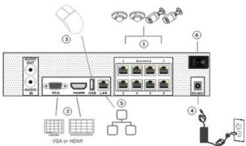
1.4 Rear Panel Descriptions
To quickly get started, connect the following to your recorder in the following order, please refer to the following figure (N8NRL shown for reference).
text_image
AUDIO OUT AUDIO IN VGA HDMI USB LAN 1 2 3 4 5 6 7 8 9 10 11 12 13 14 15 16 17 18 19 20 21 22 23 24 25 26 27 28 29 30 31 32 33 34 35 36 37 38 39 40 41 42 43 44 45 46 47 48 49 50 51 52 53 54 55 56 57 58 59 60 61 62 63 64 65 66 67 68 69 70 71 72 73 74 75 76 77 78 79 80 81 82 83 84 85 86 87 88 89 90 91 92 93 94 95 96 97 98 99 100- Connect IP cameras to the PoE ports of the recorder.
- Connect a monitor to the recorder via VGA or HDMI cable (not included).
2 Basic Operation Guide
2.1 Startup & Shutdown
Please make sure all the connections are done properly before you power on the unit. Proper startup and shutdown are crucial to expending the life of your device.
2.1.1 Startup
① Connect the output display device to the VGA/HDMI interface of the NVR.
② Connect with the mouse and power. The device will boot and the power LED would turn blue.
③ EZ setup window will pop up (you should select the display language the first time you use the NVR). Refer to 3.1 EZ Setup for details.
2.1.2 Shutdown
You can power off the device by using remote control or mouse.
By remote control:
① Press Power button. This will take you to a shutdown window. The unit will power off after a while by clicking "OK" button.
② Disconnect the power.
By mouse:
① Click Start→Shutdown to pop up the Shutdown window. Select "Shutdown" in the window. The unit will power off after a while by clicking "OK"
button.
② Disconnect the power.
2.2 Remote Control
① It uses two AAA size batteries.
② Open the battery cover of the remote control.
⑧ Place batteries. Please take care the polarity (+ and -).
④ Replace the battery cover.
Key points to check in case the remote doesn't work.
- Check batteries polarity.
- Check the remaining charge in the batteries.
- Check IR controller sensor for any masking.
If it still doesn't work, please change a new remote control to try, or contact your dealers. You can just turn the IR sensor of the remote control towards the IR receiver of the NVR to control it when you are controlling multiple devices by remote control.
Basic Operation Guide
NVR User Manual
2.3 Mouse Control
Mouse control in Live Display & Playback interface
In the live display & playback interface, double click on any camera window to show the window in single screen mode; double click the window again to restore it to the previous size.
In the live display & playback interface, if the Interfaces display in full screen, move the mouse to the bottom of the Interface to pop up a tool bar. The tool bar will disappear automatically after you move the mouse away from it for some time; move the mouse to the right side of the Interface to pop up a panel and the panel will disappear automatically after you move the mouse away from it.
Mouse control in text-input
Move the mouse to the text-input box and then click the box. The input keyboard will pop up automatically.
Note: Mouse is the default tool for all operations unless an exception as indicated.
2.4 Text-input Instruction
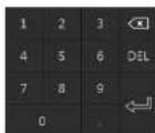

The system includes two input boxes. Refer to the above pictures. The left box is the number input box and the right box is the input box which provides inputs of numbers, letters and punctuation characters. The introductions of keys on the input boxes are shown below.
| Button | Meaning | Button | Meaning |
| Backspace key | Switch key of punctuation character | ||
| Delete Key | Enter key | ||
| Switch key between upper and lower letter | Space key | ||
| EN/11 | Switch key of language | ||
2.5 Common Button Operation
| Button Meaning | ||
| 2nd 1st 2nd 3rd 4th 5th 6th 7th 8th 9th 10th 11th 12th 13th 14th 15th 16th 17th 18th 19th 20th 21st 22nd 23rd 24th 25th 26th 27th 28th 29th 30th 31st 32nd 33rd 34th 35th 36th 37th 38th 39th 40th 41st 42nd 43rd 44th 45th 46th 47th 48th 49th 50th 51st 52nd 53rd 54th 55th 56th 57th 58th 59th 60th 61st 62nd 63rd 64th 65th 66th 67th 68th 69th 70th 71st 72nd 73rd 74th 75th 76th 77th 78th 79th 80th 81st 82nd 83rd 84th 85th 86th 87th 88th 89th 90th 91st 92nd 93rd 94th 95th 96th 97th 98th 99th 100th 101st 102nd 103rd 104th 105th 106th 107th 108th 109th 110th 111st 112nd 113rd 114th 115th 116th 117th 118th 119th 120th 121st 122nd 123rd 124th 125th 126th 127th 128th 129th 130th 131st 132nd 133rd 134th 135th 136th 137th 138th 139th 140th 141st 142nd 143rd 144th 145th 146th 147th 148th 149th 150th 151st 152nd 153rd 154th 155th 156th 157th 158th 159th 160th 161st 162nd 163rd 164th 165th 166th 167th 168th 169th 170th 171st 172nd 173rd 174th 175th 176th 177th 178th 179th 180th 181st 182nd 183rd 184th 185th 186th 187th 188th 189th 190th 191st 192nd 193rd 194th 195th 196th 197th 198th 199th 200th 201st 202nd 203rd 204th 205th 206th 207th 208th 209th 210th 211st 212nd 213rd 214th 215th 216th 217th 218th 219th 220th 221st 222nd 223rd 224th 225th 226th 227th 228th 229th 230th 231st 232nd 233rd 234th 235th 236th 237th 238th 239th 240th 241st 242nd 243rd 244th 245th 246th 247th 248th 249th 250th 251st 252nd 253rd 254th 255th 256th 257th 258th 259th 260th 261st 262nd 263rd 264th 265th 266th 267th 268th 269th 270th 271st 272nd 273rd 274th 275th 276th 277th 278th 279th 280th 281st 282nd 283rd 284th 285th 286th 287th 288th 289th 290th 291st 292nd 293rd 294th 295th 296th 297th 298th 299th 300th 301st 302nd 303rd 304th 305th 306th 307th 308th 309th 310th 311st 312nd 313rd 314th 315th 316th 317th 318th 319th 320th 321st 322nd 323rd 324th 325th 326th 327th 328th 329th 330th 331st 332nd 333rd 334th 335th 336th 337th 338th 339th 340th 341st 342nd 343rd 344th 345th 346th 347th 348th 349th 350th 351st 352nd 353rd 354th 355th 356th 357th 358th 359th 360th 361st 362nd 363rd 364th 365th 366th 367th 368th 369th 370th 371st 372nd 373rd 374th 375th 376th 377th 378th 379th 380th 381st 382nd 383rd 384th 385th 386th 387th 388th 389th 390th 391st 392nd 393rd 394th 395th 396th 397th 398th 399th 400th 401st 402nd 403rd 404th 405th 406th 407th 408th 409th 410st 411st 412nd 413rd 414th 415th 416th 417th 418th 419th 420th 421st 422nd 423rd 424th 425th 426th 427th 428th 429th 430th 431st 432nd 433rd 434th 435th 436th 437th 438th 439th 440th 441st 442nd 443rd 444th 445th 446th 447th 448th 449th 450th 451st 452nd 453rd 454th 455th 456th 457th 458th 459th 460th 461st 462nd 463rd 464th 465th 466th 467th 468th 469th 470th 471st 472nd 473rd 474th 475th 476th 477th 478th 479th 480th 481st 482nd 483rd 484th 485th 486th 487th 488th 489th 490th 491st 492nd 493rd 494th 495th 496th 497th 498th 499th 500th 501st 502nd 503rd 504th 505th 506th 507th 508th 509th 510th 511st 512nd 513rd 514th 515th 516th 517th 518th 519th 520th 521st 522nd 523rd 524th 525th 526th 527th 528th 529th 530th 531st 532nd 533rd 534th 535th 536th 537th 538th 539th 540th 541st 542nd 543rd 544th 545th 546th 547th 548th 549th 550th 551st 552nd 553rd 554th 555th 556th 557th 558th 559th 560th 561st 562nd 563rd 564th 565th 566th 567th 568th 569th 570th 571st 572nd 573rd 574th 575th 576th 577th 578th 579th 580th 581st 582nd 583rd 584th 585th 586th 587th 588th 589th 590th 591st 592nd 593rd 594th 595th 596th 597th 598th 599th 600th 601st 602nd 603rd 604th 605th 606th 607th 608th 609th 610th 611st 612nd 613rd 614th 615th 616th 617th 618th 619th 620th 621st 622nd 623rd 624th 625th 626th 627th 628th 629th 630th 631st 632nd 633rd 634th 635th 636th 637th 638th 639th 640th 641st 642nd 643rd 644th 645th 646th 647th 648th 649th 650th 651st 652nd 653rd 654th 655th 656th 657th 658th 659th 660th 661st 662nd 663rd 664th 665th 666th 667th 668th 669th 670th 671st 672nd 673rd 674th 675th 676th 677th 678th 679th 680th 681st 682nd 683rd 684th 685th 686th 687th 688th 689th 690th 691st 692nd 693rd 694th 695th 696th 697th 698th 699th 700th 701st 702nd 703rd 704th 705th 706th 707th 708th 709th 710th 711st 712nd 713rd 714th 715th 716th 717th 718th 719th 720th 721st 722nd 723rd 724th 725th 726th 727th 728th 729th 730th 731st 732nd 733rd 734th 735th 736th 737th 738th 739th 740th 741st 742nd 743rd 744th 745th 746th 747th 748th 749th 750th 751st 752nd 753rd 754th 755th 756th 757th 758th 759th 760th 761st 762nd 763rd 764th 765th 766th 767th 768th 769th 770th 771st 772nd 773rd 774th 775th 776th 777th 778th 779th 780th 781st 782nd 783rd 784th 785th 786th 787th 788th 789th 790th 791st 792nd 793rd 794th 795th 796th 797th 798th 799th 800th 801st 802nd 803rd 804th 805th 806th 807th 808th 809th 810st 811st 812nd 813rd 814th 815th 816th 817th 818th 819th 820st 821st 822nd 823rd 824th 825th 826th 827th 828th 829th 830st 831st 832nd 833rd 834th 835th 836th 837th 838th 839th 840st 841st 842nd 843rd 844th 845th 846th 847th 848th 849st 850nd 851st 852nd 853rd 854th 855th 856th 857th 858th 859st 860nd 861st 862nd 863rd 864th 865th 866th 867th 868th 869st 870nd 871st 872nd 873rd 874th 875th 876th 877th 878th 879st 880nd 881st 882nd 883rd 884th 885th 886th 887th 888th 889st 890nd 891st 892nd 893rd 894th 895th 896th 897th 898th 899st 890nd 891st 892nd 893rd 894th 895th 896th 897th 898th 899st 890nd 891st 892nd 893rd 894th 895th 896th 897th 898th 8 |
3 EZ Setup & Main Interface
3.1 EZ Setup
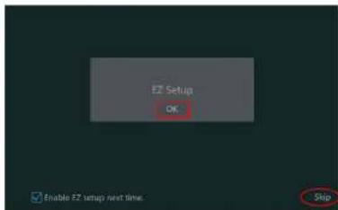
The disk icons will be shown on the top of the startup Interface. You can view the number and status of each disk quickly and conveniently through these icons (☐: no disk; ☺: unavailable disk; ☑: RW available disk).
You can quickly configure the NVR by clicking "OK" to make the NVR work normally. You must configure the wizard if you start the NVR for the first time (or click "Skip" to cancel the EZ Setup next time).
text_image
Setup OK Enable FZ setup next time. SkipClick "OK" to start wizard. The setting steps are as follows.
① System Login. Set your own password when you use the wizard for the first time (the default username of the system is admin); select the login username and enter the password you set by yourself.

text_image
EZ Setup Admin Password Setup Username: Default New Password: Lower Password Confirm Password: Lower Password Display Password Log In Automatically
text_image
EZ Setup Time Zone GMT-85 New York, Toronto, Washington System Time 05/08/2018 16:20:22 Data Format March/Day/Year Time Format 24-Hour DST OFF Synchronous Manual NTP Server Inside Windows 9.07.00 Previous Next Cancel① Network Settings. Select the network work pattern as required. Check "Obtain an IP address automatically" and "Obtain DNS automatically" to get the IP address and DNS automatically (the DHCP function of the router in the same LAN should also be enabled), or manually enter them. Enter the HTTP port, RTSP port and Server port (please see 11.1.2 Port Configuration for details). Click "Next" to continue.

text_image
EZ Setup EZ Network - Other Network & Settings Element Part 1 (Online) □ Default and 200000000000000000000000000000000000000000000000000000000000000000000000000000000000 Address: 256, 138, 1, 1, 1, 1, 1, 1, 1, 1, 1, 1, 1, 1, 1, 1, 1, 1, 1, 1, 1, 1, 1, 1, 1, 1, 1, 1, 1, 1, 1, 1, 1, 1, 1, 1 □ Default Pack: 254, 798, 254, 8, 8, 8, 8, 8, 8, 8, 8, 8, 8, 8, 8, 8, 8, 8, 8, 8, 8, 8, 8, 8, 8, 8, 8, 8, 8, 8, 8, 8, 8, 8, 8, 8, 8 □ Default Band automaticity □ Default Band: 5, 4, 4, 4, 4, 4, 4, 4, 4, 4, 4, 4, 4, 4, 4, 4, 4, 4, 4, 4, 4, 4, 4, 4, 4, 4 □ Altitude Band: HTP Pack: 63 HTP Band: 63 HTP Pack: 63 HTP Band: 63 HTP Band: 63 HTP Band: 63 HTP Band: 63 HTP Band: 63 HTP Band: 63 HTP Band: 63 HTP Band: 63 HTP Band: 63 HTP Band: 63 HTP Band: 63 HTP Band: 63 HTP Band: 65 HTP Band: 65 HTP Band: 65 HTP Band: 65 HTP Band: 65 HTP Band: 65 HTP Band: 65 HTP Band: 65 HTP Band: 65 HTP Band: 65 HTP Band: 65 HTP Band: 65 HTP Band: 65 HTP Period: HTP Period: HTP Period: HTP Period: HTP Period: HTP Period: HTP Period: HTP Period: HTP Period: HTP Period: HTP Period: HTP Period: HTP Period: HTP Period: HTP Period: HTP Period: HTP Period: HTP Period: HTP Period: HTP Period: HTP Period: | HTP Period: HTP Period: HTP Period: HTP Period: HTP Period: HTP Period: HTP Period: HTP Period: HTP Period: HTP Period: HTP Period: HTP Period: HTP Period: HTP Period: HTP Period: HTP Period: HTP Period: HTP Period: HTP Period: HTP Period:④ Other Network Settings.
UPnP settings: Check "Enable" In the interface and enter the port of external and then click "Test" to test the effectiveness of the Input information. If the UPnP status were "Invalid UPnP", the port number may be wrong. Click to modify the port until the UPnP status turns to "Valid UPnP". Refer to the following picture. You can view the external IP address of the NVR. Enter the external IP address plus port in the address bar of your browser to access the NVR. (please see 11.1.6.UPnP Configuration for details).
DDNS Settings: Check "Enable" and then select the DDNS type. Enter the server address, domain name, username and password according to the selected DDNS type. And then click "Register" or "Test" to test the effectiveness of the domain name. If it is effective, you can enter the
EZ Setup & Main Interface
NVR User Manual
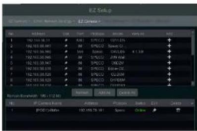
be added to the corresponding channel. To add cameras from the LAN, make sure all cameras are set to DHCP. Click "Refresh" to refresh the list of online IP cameras which are in the same local network with NVR and then click + to add the searched camera. Click "Add All" to add all the cameras in the list. Click 📄 to delete the added camera. Click "Delete All" to delete all the added cameras.
text_image
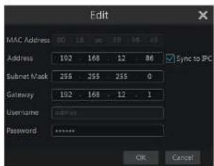
E2 Setup File Edit View Insert Tools Help 1 100.100.00.13 2 100.100.00.14 3 100.100.00.15 4 100.100.00.16 5 100.100.00.17 6 100.100.00.18 7 100.100.00.19 8 100.100.00.20 9 100.100.00.21 10 100.100.00.22 11 100.100.00.23 12 100.100.00.24 13 100.100.00.25 14 100.100.00.26 15 100.100.00.27 16 100.100.00.28 17 100.100.00.29 18 100.100.00.30 19 100.100.00.31 20 100.100.00.32 21 100.100.00.33 22 100.100.00.34 23 100.100.00.35 24 100.100.00.36 25 100.100.00.37 26 100.100.00.38 27 100.100.00.39 28 100.100.00.40 29 100.100.00.41 30 100.100.00.42 31 100.100.00.43 32 100.100.00.44 33 100.100.00.45 34 100.100.00.46 35 100.100.00.47 36 100.100.00.48 37 100.100.00.49 38 100.100.00.50 39 100.100.00.51 40 100.100.00.52 41 100.100.00.53 42 100.100.00.54 43 100.100.00.55 44 100.100.00.56 45 100.10Click to edit the searched IP camera as shown on the below left. Enter the new IP address, subnet mask, gateway, username and the password of the camera. You can check "Sync to IPC" to modify the IP address of the IPC via different network segments for being in the same network segment with the NVR. Click "OK" to save the settings.
text_image
Edit MAC Address 00 18 26 38 56 48 Address 102 168 12 86 Sync to IPC Subnet Mask 255 255 255 0 Gateway 192 168 12 1 Username: 34*10 Password: ***** OK Cancel
text_image
Edit Camera Camera Name: Camera1 Address: 192 168 12 152 Sync to IPC Port: 80 Protocol: Model: Username: admin Password: ****** Text Off CancelClick to edit the added camera as shown on the above right. Enter the new camera name, IP address, port, username and the password of the camera. You can click "Test" to test the effectiveness of the input information. Click "OK" to save the settings. You can change the IP camera name only when the added camera is online. Click "Next" to continue.
EZ Setup & Main Interface
NVR User Manual
Manual: Set the "Sensor Record", "Motion Record" and "Schedule Record" of each camera. Click "OK" to save. See 7.1.1 Mode Configuration for details.

text_image
E2 Setup E:\Users\Current Settings\E:\Users\E2 Settings\E2 Record Mode Standard Current Settings: Current Settings = Current Settings = Current Settings 200%QRCode. Enable the NAT function in the interface or set it in the network configuration after exiting the wizard (please refer to 11.1.7 NAT Configuration for details). You can scan the QRCode Through the Speco Blue App available for iOS and Android to easily and securely view your cameras. Please refer to 12.1 Mobile Client Surveillance for details. Click "OK" to save the settings.
3.2 Main Interface
3.2.1 Main Interface Introduction

text_image
New Video New Video New Video New Video New Video New Video New Video New Video New Video New Video New Video New Video New Video New Video New Video New Video New Video New Video New Video New Video New Video New Video New Video New Video New Video New Video New Video New Video New Video New Video New Video New Video New Video New Video Next Step 10:00:00:00:00:00:00:00:00:00:00:00:00:00:00:00:00:00:00:00:00:00:00:00:00:00:00:00:00:00:00:00:00:00:03:28:34The buttons in area ① are introduced in the table below
EZ Setup & Main Interface
NVR User Manual
| Button Meaning | ||
| Alarm status button. Click it to view the alarm status. | ||
| Disk status button. Click it to view the disk status and RAID status. | ||
| Network status button, Click it to view the network status. | ||
| Information button. Click it to view system information. | ||
Introduction of area ②:
Click "Camera" to view all the added cameras in the camera list. Select one camera window on the left side of the interface and then double click one camera in the list to preview the camera image in the selected window.
Click "Single Channel Sequences" to view all the added groups in the group list; click one group in the list to view all the added cameras in the group (refer to 4.2 Add/Edit Camera Group for detail configuration of the camera group). Select one camera window on the left side of the Interface and then double click one group in the group list to preview the cameras' images one by one in the selected window.
Click "Customize Layout" to view all the display modes in the display mode list (refer to 5.2.1 Display Mode for detail configuration of the display mode). Double click one display mode in the list to switch to the display mode for viewing.
Introduction of area ③:
| Icon / Button | Meaning |
 | It shows the current login user. |
| Search and Export | Click it to go to record search and export interface, see 8.3 Record Search, Playback & Export for details. |
 | Click it to go to playback interface (click on the tool bar at the bottom of the live view interface to set the default playback time), see 8.2 Playback Interface Introduction, for details. |
| Click it to pop up the setup panel, see 3.2.2 Setup Panel for details. | |
| Logout | Click it to log out the system. |
 | Click it and then select "Logout", "Reboot" or "Shutdown" in the popup window. |
| EZ Setup | Click it to go to the EZ setup. |

EZ Setup & Main Interface
NVR User Manual
Here we take Camera module as an example, The Camera module provides convenient links such as "Add Camera", "Edit Camera", "Image Settings", "Motion", "Intelligence Analysis" and "PTZ". Click Camera to go to the camera management interface as shown below.

text_image
C:\MACHINE\Manager Camera C:\Users\Networks\AutoCAD\AutoCAD\Control\System\AutoCAD\Control\System\AutoCAD\Control\System\AutoCAD\Control\System\AutoCAD\Control\System\AutoCAD\Control\System\AutoCAD\Control\System\AutoCAD\Control\System\AutoCAD\Control\System\AutoCAD\Control\System\AutoCAD\Control\System\AutoCAD\Control\System\AutoCAD\Control\System\AutoCAD\Control\System\AutoCAD\Control\System\Control\System\AutoCAD\Control\System\AutoCAD\Control\System\AutoCAD\Control\System\AutoCAD\Control\System\AutoCAD\Control\System\AutoCAD\Control\System\AutoCAD\Control\System\AutoCAD\Control\System\AutoCAD\Control\System\AutoCAD\Control\System\AutoCAD\Control\System\AutoCAD\Control\System\AutoCAD\Control\System\AutoCAD\Platform 1 PC Camera 12.00.12.135 80 OFFload Navistar 01-03-2015 1 2 PC 79.00.14.154 8000 OFFload P Camera 01-06/2015 1 3 PC 151.00.165.201 8000 OFFload P Camera 01-06/2015 1 Motion Value Settings Investment Analysis Device & System Residual System Residual & System F12 Model: AutoCAD @ Camera Size Number 3 Rscum: Ryabidin 06 / No. 1/10There are some function Items on the left side of the camera management Interface. Click each Item to go to corresponding Interface or window. For instance, click "Add Camera" to pop up the window as shown below.
text_image
Add Camera Add Mode No. Address Port Edit Select Mode Printout Model 1 10.20.17.9 9000 253.250.0.0 IP Camera 2 10.20.17.10 9000 253.250.0.0 IP Camera 3 10.20.16.4 9000 253.250.0.0 IP Camera 4 10.20.16.8 9000 253.250.0.0 IP Camera 5 10.20.15.13 9000 253.250.0.0 IP Camera 6 10.20.15.22 9000 253.250.0.0 IP Camera Selected: 9 / 28 Refresh Add Delete All No. IF Camera Name A Address Protect Status Help Orders 1 IPC 10.20.14.164 IP Camera Offset 2 IPC 193.148.225.393 IP Camera Offset Server Best Made: 48 / MB/ Mb Advanced CancelEZ Setup & Main Interface
NVR User Manual
Disk
The module covers the functions such as Disk Management, Storage Mode and Disk Information and so on. Please see Chapter 7 Record & Disk Management for details.
Network
The module covers the functions such as TCP/IP, DDNS, Port, E-mail and Network Status and so on. Please see 11.1 Network Configuration for details.
Account and Authority
The module covers the functions such as Account Management (see 10.1 Account Management for details) and Permission Management (see 10.3 Permission Management for details) and so on.
System
The module covers the functions such as Basic Configuration (see 11.2 Basic Configuration for details), Device Information (see 11.8 View System Information for details), Log Information (see 11.7 View Log for details) and Configuration File Import&Export (see 11.5 Backup and Restore for details) and so on.
4 Camera Management
4.1 Add/Edit Camera
4.1.1 Add Camera
The network of the NVR should be set before adding IP camera (see 11.1.1 TCP/IP Configuration for details).
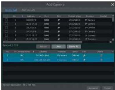
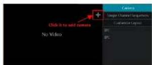
Refer to the pictures below. Click Add Camera In the setup panel or + In the top right corner of the preview window to pop up the "Add Camera" window as shown below. You can quickly add or add the IP camera manually.


text_image
Add Camera Control Sub: Add Media Player Record View 1 Address - Font 250.250.0 IP Camera 1 10.20.17.6 8008 250.250.0 IP Camera 2 10.20.17.10 8008 250.250.0 IP Camera 3 10.20.18.4 8008 250.250.0 IP Camera 4 10.20.18.8 8008 250.250.0 IP Camera 5 10.20.18.15 8008 250.250.0 IP Camera 6 10.20.18.27 8008 250.250.0 IP Camera Selected: 0 / 23 Input: Add Delete All No IP Camera Before Address Protocol Style Edit Delete 1 IPC 10.20.18.194 IP Camera Offset 2 IPC 163.348.529.203 IP Camera Offset Named Bandwidth: 46 / 19 Bits Advanced Cancel> Quickly Add
Check the cameras and then click "Add" to add cameras. Click to edit the camera's IP address, username and password and so on. Click "Default Password" to set the default username and password of each camera.
Camera Management
NVR User Manual
effectiveness of the input information and then click "Add" button (you can input one camera's information or above such as IP address, username and password before clicking "Add" button). Click 📄 to delete the camera. Click "Default Password" to set the default username and password of each camera.
Note: Some models may not support this function.
Click Start→Settings→System→Basic→General Settings to check "Enable Add IPC by Zero Operation". If the NVR has unoccupied channels, it can add IPC without any operation by restarting.
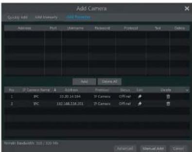
Add Recorder
text_image
Add Camera Query Info Initial Manual Add Camera Address Port Username Protocol Protocol Color Add Delete All No: IP Camera Name: 1.0 Address: Port: Username: Protocol: Status: Low: Delete 1 IPC 10.30.14.194 IP Camera Off ref # 2 IPC 182.168.216.201 IP Camera Off ref # New! Bandwidth: 315 / 220 Hz Advanced Manual Auth... Cancel- Quickly Add : Select the searched NVR/DVR and the click "Add" to add NVR in the same local network.
Manually Add : Click "Manual Add" and then enter the IP address or domain name, port, username and password of the NVR/DVR.
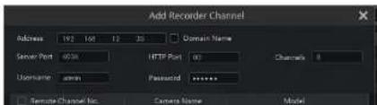
Check the added remote channel number and click "Test" to test the effectiveness of the input information. Then click "OK" button to return to the previous interface.
text_image
Add Recorder Channel Address 192 168 12 35 Domain Name Server Port 40.00 HTTP Port 00 Channels 0 Username admin Password ****** Template Channel No. Camera Name ModelCamera Management
NVR User Manual
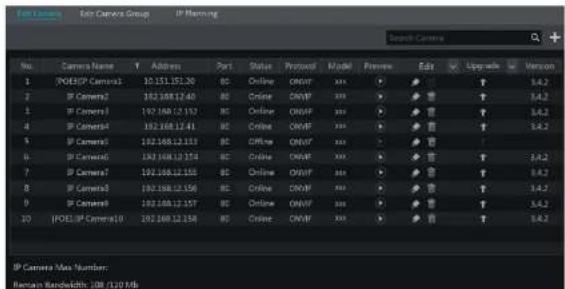
window If a batch of IPCs' passwords need to be modified) and then click "Upgrade" button to start upgrading(the IPC will restart automatically after the upgrade is completed successfully).
text_image
Camera No. Camera Name Y Address Port Status Protocol Model Preview Edit Upgrade Version 1 | POESIP Camera1 | 10.151.151.20 | BC Online OBUF xxx ▼ ▼ ▼ ▼ ▼ ▼ ▼ ▼ ▼ ▼ ▼ ▼ ▼ ▼ ▼ ▼ ▼ ▼ ▼ ▼ ▼ ▼ ▼ ▼ ▼ ▼ ▼ ▼ ▼ ▼ ▼ ▼ ▼ ▼ ▼ ▼ ▼ ▼ ▼ ▼ ▼ ▼ ▼ ▼ ▼ ▼ ▼ ▼ ▼ ▼ ▽ 2 | IP Camera2 | 192.168.12.40 | BC Online OBUF xxx ▼ ▼ ▼ ▼ ▼ ▼ ▼ ▼ ▼ ▼ ▼ ▼ ▼ ▼ ▼ ▼ ▼ ▼ ▼ ▼ ▼ ▼ ▼ ▼ ▼ ▼ ▼ ▼ ▼ ▼ ▼ ▼ ▼ ▼ ▼ ▼ ▼ ▼ ▼ ▼ ▼ ▼ ▼ ▼ ▼ ▼ 3 | IP Camera3 | 192.168.12.52 | BC Online OBUF xxx ▼ ▼ ▼ ▼ ▼ ▼ ▼ ▼ ▼ ▼ ▼ ▼ ▼ ▼ ▼ ▼ ▼ ▼ ▼ ▼ ▼ ▼ ▼ ▼ ▼ ▼ ▼ ▼ ▼ ▼ 4 | IP Camera4 | 192.168.12.41 | BC Online OBUF xxx ▼ ▼ ▼ ▼ ▼ ▼ ▼ ▼ ▼ ▼ ▼ ▼ ▼ ▼ ▼ ▼ ▼ ▼ ▼ ▼ ▼ ▼ ▼ ▸ 5 | IP Camera5 | 192.168.12.53 | BC Open OBUF xxx √ ☑ ☑ ☑ ☑ ☑ ☑ ☑ ☑ ☑ ☑ ☑ ☑ ☑ ☑ ☑ ☑ ☑ ☑ ☑ ☑ ☑ ☑ ☑ ☑ ☑ ☑ ☑ ☑ ☑ ☑ ☑ ☑ ☑ ☑ ☑ ☑ ☑ ☑ ☑ ☑ ☑ ☑ ☑ ☑ ☑ ☑ ☑ ☑ ☑ ☑ ☐ 6 | IP Camera6 | 192.168.12.54 | BC Online OBUF xxx √ ☑ ☑ ☑ ☑ ☑ ☑ ☑ ☑ ☑ ☑ ☑ ☑ ☑ ☑ ☑ ☑ ☑ ☑ ☑ ☑ ☑ ☑ ☑ ☑ ☑ ☑ ☑ ☑The IP cameras with PoE function which directly connect to the PoE port of the NVR will be displayed automatically in the camera list. Refer to the picture below. The IP camera which occupies the PoE resource has a prefix shown before its camera name. The prefix consists of PoE plus PoE port number. The IP camera which connects to the PoE port cannot be deleted from the camera list manually.
The IP camera which directly connects to the PoE port of the NVR through private protocol will be shown automatically in the camera list.
- One of the two conditions must be met if the IP camera which directly connects to the PoE port of the NVR through ONVIF protocol should be shown automatically in the camera list.
√ The IP camera which directly connects to the PoE port is in the same network segment with the internal ethernet port.
√ The DHCP (obtain an IP address automatically) of the IP camera which directly connects to the PoE port is enabled.
If the IP camera which connects to the PoE port cannot be displayed automatically in the camera list, please refer to Q6 in Appendix A FAQ for details.
4.2 Add/Edit Camera Group
4.2.1 Add Camera Group
Click "Edit Camera Group" in the above interface to go to the interface as shown below.

Camera Management
NVR User Manual
4.2.2 Edit Camera Group

text_image
Edit Camera Edit Camera Group IP Planning Group1 Dwell Time ( 10 Spcs ) Number of Cameras( 2 ) IP Camera1 IP Camera2 Group2 Dwell Time ( 10 Spcs ) Number of Cameras( 2 ) IP Camera3 IP Camera4Click to modify the group information such as group name and dwell time. Click to delete the group.
4.2.3 IP Planning
Some models may not support this function.
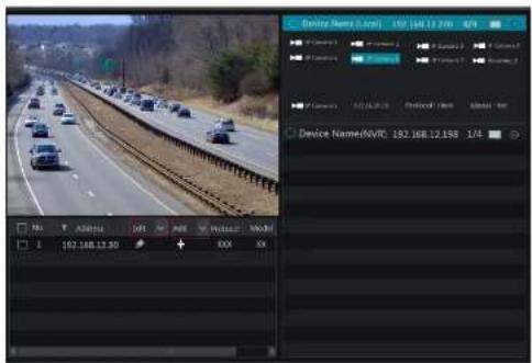
Click "IP Planning" to go to the interface as shown below. This function supports searching other NVRs/DVRs that is in the same local network as the local NVR. The user may add camera channels of other NVRs/DVRs into the unoccupied channels of the local NVR.
text_image
Device Name: 0.001 192.168.12.200 4/4 Device Name:0.001 192.168.12.200 4/4 Device Name:0.001 192.168.12.200 4/4 Device Name:0.001 192.168.12.200 4/4 Device Name:0.001 192.168.13.20 4/4 Device Name:0.001 192.168.13.20 4/4 Device Name:0.001 192.168.13.20 4/4 Device Name:0.001 192.168.13.20 4/4 Device Name:0.001 192, 168, 12, 158 1/45 Live View Introduction
5.1 Live View Interface Introduction
You should add camera first after logging on to the system (see 4.1.1 Add Camera for details). Refer to the interface as shown below, drag one camera in the preview window to another window for camera window exchanging.
The record symbols with different colors in the live view window refer to different record types when recording: green stands for manual record, red stands for sensor based record, yellow stands for motion based record, blue stands for schedule record and cyan stands for intelligence record.

text_image
Screenshot of a video editing interface showing highway traffic with a camera control panel and playback controlsClick the preview window to show the tool bar as shown in area ①; right click the preview window to show the menu list. The tool bar and menu list are introduced in the table below.
| Button | Menu List | Meaning |
| -- | Move soul. Click it to move the tool bar anywhere. | |
| Manually Record On | Click it to start recording. | |
| Instant Playback | Clickto playback the record; click "instant Playback" to select or self-define the instant playback time. See 8.1 Instant Playback for details. | |
| Enable Audio | Click it to enable audio. You can listen to the camera audio by |
Live View Introduction
NVR User Manual
natural_image
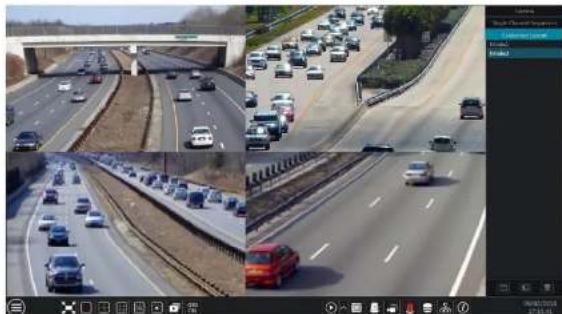
Highway traffic scene with multiple lanes and cars, inset shows a close-up of a highway with visible tracks (no text or symbols)5.2 View Mode
5.2.1 Display Mode
Set different screen modes and cameras' display sequences as needed and then save the display modes classified by surveillance areas, priorities and so on. Refer to the picture below. Double click one display mode in the display mode list to view the live images in this mode.
natural_image
Composite image showing multiple highway traffic scenes with vehicles and a red car, displayed in a video editing interface (no readable text or symbols)Live View Introduction
NVR User Manual
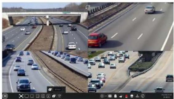
5.2.2 Quick Sequence View
You can start quick sequence view if the scheme has not been created. If the scheme has been created, please refer to 5.2.4 Scheme View in Sequence for details.
natural_image
Composite image showing a multi-lane highway with traffic and a red truck, no visible text or symbols.Go to the live view interface and then click 📄 to pop up a little window. Set the dwell time in the window and then click 📄 to view the live group by group according to the camera number of the current screen mode. Double click the sequence view interface to pause the view; double click again to restore the view. Click 📄 to stop the view.
5.2.3 Camera Group View In Sequence
You can start camera group view in sequence if camera group has been created (see 4.2.1 Add Camera Group for details). ① Go to the live view interface and then select a camera window.

natural_image
Composite highway traffic scene with multiple lanes and a highlighted lane (no visible text or symbols)Live View Introduction
NVR User Manual
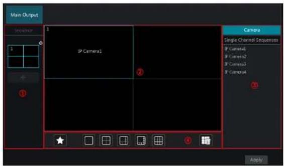
④ Is the tool bar (☐) clear button; ⚠: favorite button, click it to pop up a window, enter the display mode name in the window and then click "OK" to save the current display mode; other buttons are screen mode buttons).
text_image
Main Output Sequence 1 IP Camera1 Camera1 Single Channel Sequences IP Camera1 IP Camera2 IP Camera3 IP Camera4 ApplyAdd Scheme
Click + in area ① to create a new scheme. Click ✗ on the top right corner of the scheme to delete it.
Configure Scheme
a) Select a scheme in area ① and then click the screen mode button on the tool bar to set the screen mode of the scheme.
b) Select a camera window in area ② and then double click the camera or group in area ③. The camera or group will be added into the selected window. One camera in the same scheme cannot repeat. You can click the right-click menu "Clear" in area ② to remove a single camera or click to remove all the cameras.
c) Click "Apply" to save the settings.
Start Sequence View
Go to the live view interface and then click 📄 to open a window. Set the dwell time in the window and then click 📄 to start scheme view in sequence. Double click the sequence view Interface to pause the view; double click again to restore the view. Click 📄 to stop the view.
5.3 Image Configuration
Live View Introduction
NVR User Manual
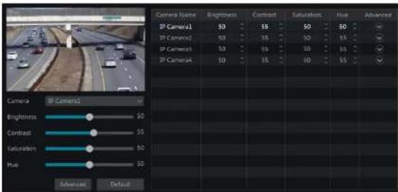
5.3.2 Image Settings
Click Start→Settings→Camera→Image→Image Settings to go to the following interface. Select the camera and then set the brightness, contrast, saturation and hue of the camera. Click "Advanced" button or in the camera list on the right side of the interface to pop up "Image Adjust" interface and then set the relevant setting items. Please refer to 5.3.4 Image Adjustment for detailed introductions of these items. You can click "Default" button to restore the image settings to the default factory settings.
text_image
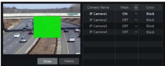
Camera Name BP Camera1 BP Camera2 BP Camera3 BP Camera4 Camera IP Camera1 Brightness Contrast Saturation Hue Advanced Default Brightness Contrast Saturation Hue Brightness Contrast Saturation Hue Brightness Contrast Saturation Hue Brightness Contrast Saturation Hue Brightness Contrast Saturation Hue Brightness Contrast Saturation Hue Brightness Contrast Saturation Hue Brightness Contrast Saturation Hue Brightness Contrast Saturation Hue Brightness Contrast Saturation Hue5.3.3 Mask Settings
Some areas of the image can be masked for privacy. Up to four mask areas can be set for each camera. Click Start→Settings→Camera→Image→Mask Settings to go to the interface as shown below. Select the camera and enable the mask. Click "Draw" button and then drag the mouse on the image area to set the mask area; click "Delete" button to delete the mask areas; click "Apply" to save the settings.
text_image
Camera Name Mask Color IP Camera1 ON Black IP Camera2 OFF Black IP Camera3 OFF Black IP Camera4 OFF Black Draw Delete
text_image
Camera IP Camera1 Image Adjust (Lens Control) Brightness 80 Contrast 10 Saturation 10 Hue 10 Sharpen 10 Wide Dynamic 10 Denoise 10 White Balance Auto Image Mirror ON OFF Image Flip ON OFF Default BackImage Adjustment
Select the camera and then click "Image Adjustment" to go to image adjustment tab. Refer to the above picture. Drag the slider to set the camera's brightness, contrast, saturation and hue value. Check sharpen, wide dynamic and denoise and then drag the slider to set the value. Click "Default" button to set these parameters to default values.
The introductions of these parameters are as follows:
| Parameter Meaning | |
| Brightness | It is the brightness level of the camera's image. |
| Contrast | It is the color difference between the brightest and darkest parts. |
| Saturation | It is the degree of color purity. The color is purcr, the image is brighter. |
| Hue | It relates to the total color degree of the image. |
| Sharpen | It relates to the resolution level of the image plane and the sharpness level of the image edge. |
| Wide Dynamic | The wide dynamic range (WDR) function helps the camera provide clear images even under back light circumstances. When there are both very bright and very dark areas simultaneously in the field of view, WDR balances the brightness level of the whole image and provide clear images with details. |
| Denoise | Adopt the noise reduction technology to decrease the noise and make the image more thorough. Increasing the value will make the noise reduction effect better but it will reduce the image resolution. |
| White Balance | White balance is the white rendition function of the camera to adjust the color |

text_image
Camera Image Adjust Area Control +Zoom + Focus Mode Manual Mode +Focus +Duty Line Focus Supporting Boundary mode: Tread the route to take off + Daylight mode with autofocus Save BackThe introductions of these parameters and buttons are as follows.
| Button/Parameter Meaning | |
| → ↑ Zoom → ↑ | Click + / - to zoom in/out the image. |
| Focus Mode | If manual mode is selected, focus button & "One Key Focus" & "Day/night mode switch autofocus" will be available; if auto mode is selected, the time interval setup will be available. |
| → ↑ Focus → ↑ | Click + / - to increase/decrease the focal length. |
| One key Focus | Click it to focus instantly. |
| Day/night mode switch autofocus | If checked, the lens will focus automatically when the camera is switching day/night mode. |
| Time Interval | It is the time interval when camera lens is auto-focusing. The interval can be set in the drop-down list. |
Note: This function is only available for motorized zoom camera, or the settings here are ineffective.
6 PTZ
6.1 PTZ Control Interface Introduction
You can control the IP dome or PTZ which connects to the IP camera for PTZ control.
Click on the tool bar at the bottom of the live view window to go to the PTZ control interface as shown below. You can select another IP dome or PTZ which connects to the IP camera on the top right of the Interface for PTZ control.

text_image
Analog Joystick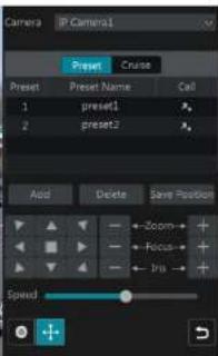
text_image
Camera P Camera1 Preset Crude Preset Preset Name Cell 1 preset1 2 preset2 Add Delete Save Position ←Zoom→+ ←Focus→+ ←Ina→+ SpeedIntroductions of the buttons on the bottom right of the interface:
text_image
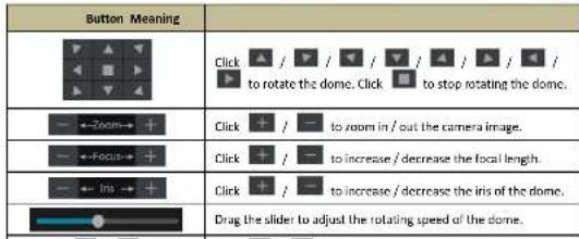
Button Meaning Click / / / / / / / / to rotate the dome. Click to stop rotating the dome. - ←Zoom→ + Click + / - to zoom in / out the camera image. - ←Focus→ + Click + / - to increase / decrease the focal length. - ← Iris → + Click + / - to increase / decrease the iris of the dome. Drag the slider to adjust the rotating speed of the dome.
text_image
Zoom L B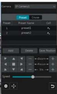
text_image
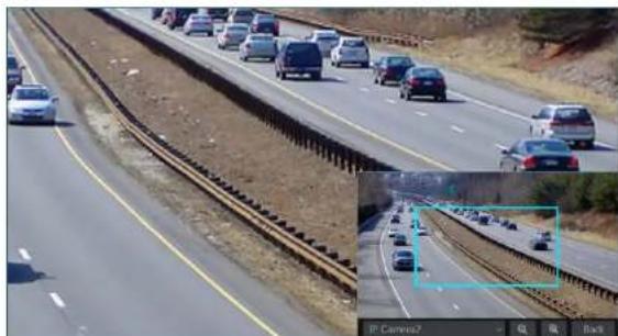
Camera [2 Camera] Preset Cruise Preset Preset Name Call 1 preset1 2 preset2 Aod Delete Save Position Zoom Focus Iris SpeedRefer to the picture as shown below. Drag the mouse from C to D to get a green rectangle and the rectangle area will be zoomed out.

natural_image
Highway scene with multiple cars and a bridge, no visible text or symbols
text_image
Camera P Camera1 Preset Cruise Preset Preset Name Call 1 preset1 2 preset2 Add Delete Save Position Zoom Focus Ins SpeedAdvanced 3D Control
then save the preset position after adjusting the dome's direction); click in the preset list to call the preset; click "Delete" button to delete the selected preset.
You can also go to preset setting interface for preset setting, see 6.2 Preset Setting for details.
Cruise Setting
Click "Cruise" to go to cruise operation tab and then click "Add" button to pop up a window as shown below left. You can add 8 cruises for each dome at most.

text_image
Add Custom Create Name (Created) Format Formal Name Symbol Time Edit Delete 1 present1 3 Show Add Point Add Cancel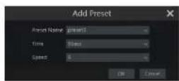
① Enter the cruise name in the "Add Cruise" window and then click "Add preset" to pop up the "Add Preset" window (Before adding preset to the cruise, please add preset of the dome first).
② In the "Add Preset" window, select the preset name, preset time and preset speed and then click "OK" button.
In the "Add Cruise" window, you can click 📄 to reselect the preset, then change the preset time and speed. Click 📋 to delete the preset. Click "Add" button to save the cruise.
Click ▶ to start the cruise and click □ to stop the cruise in the cruise list of the cruise operation tab; click "Delete" button to delete the selected cruise.
You can also go to cruise setting interface for cruise setting, see 6.3 Cruise Setting for details.
6.2 Preset Setting
Click Start→Settings→Camera→PTZ→Preset to go to the interface as shown below.

text_image
IP Camera1 Number of Preset ( 1 )Select camera and preset. You can enter the new name of the preset and then click to save the new preset name. Adjust the rotating speed, position, zoom, focus and iris of the preset and then click "Save Position" to save the preset.
Delete Preset
Select camera and preset and then click "Delete" to delete the preset.
6.3 Cruise Setting
Click Start→Settings→Camera→PTZ→Cruise to go to the Interface as shown below.

text_image
IP Camera1 Number of Cruise(1) cruise1 Camera: IP Camera1 Cruise: cruise1 Cruise Name: cruise1 Preset Preset Name Speed Time Edit 1 preset1 S 5 Secs 2 preset2 S 5 Secs Add Preset> Add Cruise
Click in the camera list on the right side of the interface to display the cruise information of the dome and then click to add cruise. The operations of the "Add Cruise" window are similar to that of the PTZ control interface; please see 6.1.PTZ Control Interface Introduction for details.
Edit Cruise
Select the camera and cruise in the "Cruise" interface. Enter the new cruise name and then click to save the cruise name. Click "Add Preset" to add preset to the cruise. Click to edit the preset. Click to delete the preset from the cruise. Click one preset in the preset list and then
7 Record & Disk Management
7.1 Record Configuration
7.1.1 Mode Configuration
Please format the HDDs before recording (refer to 7.5 Disk Management for details). Click Start→Settings→Record→Mode Settings to go to the mode settings interface. You can set the record time under the "Manual Record Settings" and then click "Apply" button to save the settings. There are two record modes: auto mode and manual mode.

text_image
Record Mode Audio Satellite Record Sensor Record Motion Record-Sensor Record Continuous Record-Motion Record Continuous Record-Sensor Record Continuous Record-Motion Record-Sensor Record Advanced Internal Record Settings Record Time: 10 ms OKAuto Mode
Motion Record: Motion alarm record will be enabled when motion alarm happens.
Sensor Record: Sensor alarm record will be enabled when sensor alarm happens.
Motion Record+Sensor Record: Motion/sensor alarm record will be enabled when motion/sensor alarm happens.
Continuous Record+Motion Record: Normal record is enabled all the time; motion alarm record will be started when motion alarm happens.
Continuous Record+Sensor Record: Normal record is enabled all the time; sensor alarm record will be started when sensor alarm happens.
Continuous Record+Motion Record+Sensor Record: Normal record is enabled all the time; motion/sensor alarm record will be enabled when
motion/sensor alarm happens.
Continuous Record+Motion Record+Sensor Record+ Analytics Record: Normal record is enabled all the time; motion/sensor/analytics alarm record will be enabled when motion/sensor/Intelligence analytics alarm happens.
You can add more auto modes on intelligence record. Click "Advanced" button to pop up a window as shown below. Check the modes in the window and then click "Add" button to show the modes in the record mode list (in the window, the checked modes can be showed in the record mode list while the unchecked modes cannot; you shall check "Analytics Record").
Record & Disk Management
NVR User Manual
text_image
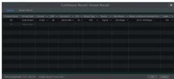
Continuous Record+Sensor Record Current Storage Format C:\Program Files\Continuous\Record\Sensor\Record PC Main Stream 1.264 80 1825109C 20 VBX Higher 32728ps 14-376bps DIV % 100% 100% System: Production 11/1/2024 Project Recorded Smart BuyVideo Encode: the available options will be H.265 and H.264 if the connected IP camera supports H.265, or the option will be H.264 only.
GOP: group of pictures.
Resolution: the higher the resolution is, the clearer the image is.
FPS: the higher the frame rate is, the more fluency the video is. However, more storage room will be taken up.
Bitrate Type: CBR and VBR are optional. CBR means that no matter how much change is seen in the video scene, the compression bitrate will be kept constant. VBR means that the compression bitrate will be adjusted according scene changes. For example, for scenes that do not have much movement, the bitrate will be kept at a lower value. This will help to optimize the network bandwidth.
Quality: When VBR is selected, you need to choose image quality. The higher the image quality you choose, the more bitrate will be required.
Max Bitrate: 32Kbps \~10240Kbps are optional.
Manual Mode
If the manual mode is selected, you need to set the encode parameters and record schedules of each camera. See 7.2 Encode Parameters Setting and 7.3 Schedule Setting for details.
7.1.2 Advanced Configuration
Click Start→Settings→Record→Advanced to go to the following interface. Enable or disable cycle record (cycle record: the earliest record data will be replaced by the latest when the disks are full). Set the pre-alarm record time, post-alarm record time and expiration time of each camera and then click "Apply" to save the settings.

Record & Disk Management
NVR User Manual
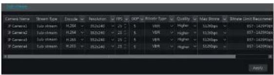
Click Start→Settings→Record→Stream Settings to go to "Sub-stream" interface. Set the encode, resolution, FPS, GOP, bitrate type, quality and max bitrate of sub-stream for each camera in the interface and then click "Apply" to save the settings.
text_image
Camera Name Stream Type Encode ReLUAR EPS SOP Altroo Type Quality Max Stroke Bitrate Limit Recalim IF Camera1 Sub stream H.204 > 352x240 < 25 S VBR > Higher > 512bps > 857-1429bps IF Camera2 Sub stream H.204 > 352x240 < 25 S VBR > Higher > 512bps > 857-1429bps IF Camera3 Sub stream H.205 > 352x240 < 25 S VBR > Higher > 512bps > 857-1429bps IF Camera4 Sub stream H.205 > 352x240 < 25 S VBR > Higher > 512bps > 857-1429bps Apply7.3 Schedule Setting
7.3.1 Add Schedule
Click Start→Settings→Record→Record Schedule→Edit Schedules to go to the interface as shown below. "24 x 7", "24 x 5" and "24 x 2" are the default schedules; you cannot edit or delete "24 x 7" while "24 x 5" and "24 x 2" can be edited and deleted. Click the schedule name to display the detailed schedule information on the left side of the Interface. The seven rows stand for the seven days in a week and each row stands for 24 hours in a day. Blue stands for the selected time and gray stands for unselected time.

text_image
Schedule Config Edit: Schedule Schedule "24x2" Mon 6000 - 24x2 Mon Sun Wed Thu Fri Sat Name Exit Delete 24x2 24x5 24x2 24x2 24x2 24x2 24x2 24x2 24x2 24x2 24x2 24x2 24x2 24x2 24x2 24x2 24x2 24x2 24x2 24x2 24x2 24x2 24x1 24x1 24x1 24x1 24x1 24x1 24x1 24x1 24x1 24x1 24x1 24x1 24x1 24x1 24x1 24x1 24x1 24x1 24x1 24x1 24x0 - 24x0Record & Disk Management
NVR User Manual
Click and then drag the cursor on the time scale to set record time; click and then drag the cursor on the time scale to delete the selected area.
You can manually set the record start time and end time. Click or and then click "Manual" on each day to pop up a window as shown below. Set the start and end time in the window and then click "OK" to save the settings.
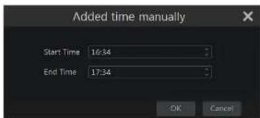
text_image
Added time manually Start Time 16:34 End Time 17:34 OK CancelClick "All" to set all day recording; click "Reverse" to swap the selected and unselected time in a day; click "Clear All" to clear all the selected area in a day.
Click "Copy To" to copy the schedule of the day to other days. Refer to the picture below. Check the days in the window and then click "OK" to save the settings.
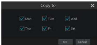
text_image
Copy to ✓ Mon ✓ Tues ✓ Wed ✓ Thur ✓ Fri ✓ Sat OK CancelSet Week Schedule
Click 📄 or 📋 and then click "Manual" beside 📋 to set the week schedule. Refer to the picture below. Set the start and end time, check the days in the window and then click "OK" to save the settings.

Record & Disk Management
NVR User Manual

text_image
Current Name Current Schedule PC PC Current Schedule Current Name Current Schedule Current Name Current Schedule Current Name Current Schedule Current Name Current Schedule Current Name Current Schedule Current Name Current Schedule Current Name Current Schedule Current Name Current Schedule Current Name Current Schedule Current Name Current Schedule Current Name Current Schedule Current Name Current Schedule Current Name Current Schedule Current Name Current Schedule Current Name Current Schedule Current Name Current Schedule Current Name Current ScheduleGo to "Edit Schedules" interface and then click to edit the schedule. The settings of "Edit Schedule" are similar to that of the "Add Schedule". Click delete the schedule.
7.4 Record Mode
7.4.1 Manual Recording
Method One: Click on the tool bar at the bottom of the live view interface to enable recording of the camera.
Method Two: Go to the live view interface and then click the right-click menu "Manually Record On" in the camera window or click on the tool bar under the camera window to start recording.
Note: Click Start→Settings→Record→Mode Settings and then set the manual record time in the interface. Click "Apply" to save the settings.
7.4.2 Timing Recording
Timing Recording: the system will record automatically according to the schedule.
Set the timing record schedule of each camera. See 7.3 Schedule Setting for details.
7.4.3 Motion Based Recording
Motion Based Recording: the system will start motion based recording when the motion object appears in the setup schedule. The setup steps are as follows:
① Set the motion based recording schedule of each camera. See 7.3 Schedule Setting for details.
② Enable the motion and set the motion area of each camera. See 9.2.1 Motion Configuration for details.
Record & Disk Management
NVR User Manual
text_image
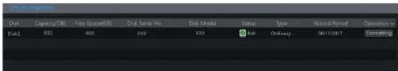
CPU Capacity(GB) Free Storage(GB) Ctrl Server No. Disk Model Status Type Record Version Operations CPU1 552 600 800 200 300 400 500 600 700 800 900 1000 1100 1200 1300 1400 1500 1600 1700 1800 1900 2000 2100 2200 2300 2400 2500 2600 2700 2800 2900 3000 3100 3200 3300 3400 3500 3600 3700 3800 3900 4000 4100 4200 4300 4400 4500 4600 4700 4800 4900 5000 5100 5200 5300 5400 5500 5600 5700 5800 5900 6000 6100 6200 6300 6400 6500 6600 6700 6800 6900 7000 7100 7200 7300 7400 7500 7600 7700 7800 7900 8000 8100 8200 8300 8400 8500 8600 8700 8800 8900 9000 9100 9200 9300 9400 9500 9600 9700 9800 9900Some models may not support this function. The settings of RAID are as followings. Please skip the settings of physical disk, array and disk mode if the NVR doesn't support this function.
Note 1. The new HDD should be formatted for normal use.
- For normal use of the HDD which has been used in other NVR, if the NVR is of the same model with the new NVR, please import the configuration file of the NVR to the new NVR or format the HDD; if the models of the two NVRs are different, please format the HDD.
7.5.2 Storage Mode Configuration
Click Start→Settings→Disk→Storage Mode to go to the interface as shown below.
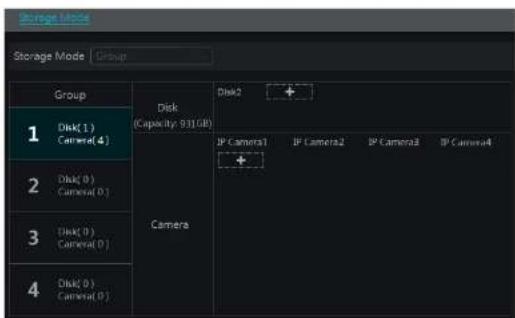
text_image
Storage Mode Storage Mode Group Group Disk(1) Camera(4) Disk(0) Camera(0) Disk(0) Camera(0) Disk(0) Camera(0) Disk2 + IP Camera1 IP Camera2 IP Camera3 IP Camera4 + Camera 2 3 4There are all four disk groups. By using disk group, you can correspond the camera to disk (the record data of the camera in the group will be stored into the disks in the same group). The NVR with e-SATA interface supports e-SATA recording.
text_image
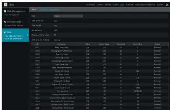
Disk Management Market Storage Media Storage Market Disk New information - CCAT Information Disk Service Disk Initial Inventory Power to Time (ms) Disk & ACAT Status Name Value Short Value Tangible Key Value Balance Add Stock Value 200 200 52 0 Normal Add Trading Performance 1.68 1.68 40 0 Normal Add Stock Price 214 214 33 7 Normal Add Trading Support Count 200 200 0 66 Normal Add Market Sector Count 200 200 0 0 Normal Add Stock Rating 200 200 47 0 Normal Add Stock Price Index 200 200 40 0 Normal Add Stock Price Range Chart 200 200 0 724 Normal Add Stock Price Range Chart 200 200 0 63 Normal Add Stock Price Range Chart 200 200 0 54 Normal Add Stock Price Range Chart 200 200 0 6815 Normal Add Stock Price Range Chart 200 200 0 195952 Normal Add Stock Price Range Chart 200 200 0 0 Normal Add Stock Price Range Chart 200 200 0 195952 Normal8 Playback & Export
8.1 Instant Playback
Click ▶ on the tool bar at the bottom of the preview camera window to play back the record (click ▶ on the tool bar at the bottom of the live view interface to set the default playback time). Refer to the picture below. Drag the playback progress bar to change the playback time. You can also click the right-click menu "Instant Playback" in the camera window and then set the instant playback time to play back the record.

natural_image
Interior view of a modern building with large windows and a person standing near a railing (no visible text or symbols)8.2 Playback Interface Introduction
Click 📄 on the tool bar at the bottom of the live view interface or click Start→Playback to go to the playback interface as shown below (click 📄 on the tool bar at the bottom of the live view interface to set the default playback time).
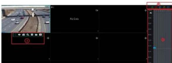
text_image
No Data| Button Meaning | |
| Full screen button. Click it to show full screen; click it again to exit the full screen. | |
| Screen mode button. | |
| OSD ON button. Click it to enable OSD; clickto disable OSD. | |
| Stop button. | |
| Rewind button. Click it to play video backward. | |
| Play button. Click it to play video forward. | |
| Pause button. | |
| Deceleration button. Click it to decrease the playing speed. | |
| Acceleration button. Click it to increase the playing speed. | |
| Previous frame button. It works only when the forward playing is paused in single screen mode. | |
| Next frame button. It works only when the forward playing is paused in single screen mode. | |
| Clickto stop backward 30s and clickto stop forward 30s. | |
| Event list/tag button. Click it to view the event record of manual/schedule/sensor/ motion and the tag information. | |
| Backup button. Drag the mouse on the time scale to select the time periods and cameras, and then click the button to back up the record. | |
| Backup status button. Click it to view the backup status. | |
| Back button. Click it to return. | |
| Full screen motion button. | |
| Motion button. | |
| Draw line button. You can search the record of crossing the line after drawing the line. | |
| Draw quadrilateral. You can search the record in this quadrilateral after drawing it. | |
| Smart playback settings. Click it to set smart playback. | |
Introduction of area ②:
| Button Meaning | |
| Click it to go to record search and export interface; see 8.3 Record Search.Playback & Export for details. | |
| Click it to Go to the live view interface; see Chapter 5 Live View Introduction | |
Playback & Backup
NVR User Manual
Introduction of area ④:
You can check the record type as required for record playback; first you should click ☐ on the tool bar at the bottom of the Interface to clear all the playback camera, then check the record type [☐: manual record; ☐: sensor based record; ☐: motion based record; ☐: schedule record; ☐: analytics record; and finally click + in the playback window to add camera for playback {the record time scale will show the record data of the checked record type only after the above operations).
Introduction of the record time scale (area ⑤):
Click 📋 to set the date; click 🔒 to set the time and then the playback camera will play the record from the time you set.
A tool bar will appear after moving the mouse to the record time scale. Click / to zoom the timeline; click to recover the timeline to 24 hours' ratio. Drag the timeline or slide the scroll wheel of the mouse on the time scale to show the hidden time on the top or bottom of the timeline. You can also click to show the hidden time on the top of the timeline or click to show the hidden time on the bottom of the timeline. Drag the slider at the bottom of the time scale to show the hidden playback cameras.
The record time scale shows different record types with different colors. The green block stands for manual record, red block stands for sensor based record, yellow block stands for motion based record, blue block stands for schedule record and cyan block stands for intelligence record. Click the record block to set the time and then the playback camera will play the record from the time you set.
Drag the color block on the time scale to select the backup area and then right click the area or click to pop up a export information window. Click button in the window to pop up the export window. Select the device, export path and format and then click "Export" button to start the backup.
8.3 Record Search, Playback & Export
The record data and the captured pictures can be exported through network, USB (U disk or USB mobile HDD). The file system of the export devices should be FAT32 format.
8.3.1 EZ Search
① Click Start→Search and Export→EZ Search to go to the "EZ Search" tab. There are two view modes: by time and by camera. In the time view mode, a maximum of 64 camera thumbnails can be showed. If the camera thumbnail number is more than 64, the cameras will be listed directly by their camera name, not the thumbnail. A maximum of 196 camera names can be listed. If the camera name number is more than 196, the time view mode will be disabled and the camera view mode will be available only.

text_image
Search and Export Current Search View Black: Save B1/0028.13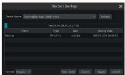
text_image
Record Backup Device Name ExternalStorage: 0808-4ACI Refresh Free:28.96 GB/All: 29.27 GB Name Type Size Modify Date Backup Directory 8.00 KB 2011/11/03 16:54:53 Format Private New Folder Delete Export CancelNote: If you back up the record in private format, the system will back up a RPAS player to USB device automatically. The private format record can be played by RPAS player only.
⑤ Click "Playback" button to play the record in the playback interface (refer to 8.2 Playback Interface introduction for details). Click "Exit" to exit the interface.

text_image
Search and Export File Edit View Tools Help Tools Help Settings Save Settings Preview Help Tools Search and Export File Edit View Tools Help Tools Help Settings Help Settings Save Settings Preview Help Tools Macromedia - 1. Macromedia - 1. Macromedia - 1. Macromedia - 1. Macromedia - 1. Macromedia - 1. Macromedia - 1. Macromedia - 1. Macromedia - 1. Macromedia - 1. Macromedia - 1. Macromedia - 1. Macromedia - 1. Macromedia - 1. Macromedia - 1. MacromMedia Macromedia - 1. Macromedia - 1. Macromedia - 1. Macromedia - 1. Macromedia - 1. Macromedia - 1. Macromedia - 1. Macromedia - 1. Macromedia - 1. Macromedia - 1. Macromedia - 1. Macromedia - 1. Macromedia - 1. Macromedia - 1. MACOMedia Macromedia - 1. Macromedia - 1. Macromedia - 1. Macromedia - 1. Macromedia - 1. Macromedia - 1. Macromedia - 1. Macromedia - 1. Macromedia - 1. Macromedia - 1. Macromedia - 1. Macromedia - 1. Macromedia - 1. Macromedia - 1. PC Macromedia - 1. PC Macromedia - 1. PC Macromedia - 1. PC Macromedia - 1. PC Macromedia - 1. PC Macromedia - 1. PC Macromedia - 1. PC Macromedia - 1. PC Macromedia - 1. PC Macromedia - 1. PC Macromedia - 1. PC Macrorim Macrorim Macrorim Macrorim Macrorim Macrorim Macrorim Macrorim Macrorim Macrorim Macrorim Macrorim Macrorim Macrorim Macrorim Macrorim Macrorim Macrorim Macrorim Macrorim Macrorim Macrorim Macrorim Macrorim Macrorim Macrorum Macrorum Macrorum Macrorum Macrorum Macrorum Macrorum Macrorum Macrorum Macrorum Macrorum Macrorum Macrorum Macrorum Macrorum Macrorum Macrorum Macrorum Macrorum Macrorum Macrorum Macrorum Macrorum Macrorum Macrorum Macroru Macroru Macroru Macroru Macroru Macroru Macroru Macroru Macroru MacroruPlayback & Backup
NVR User Manual

text_image
Search and Export 06/13/2018 09:29:24 File CameraOut8.3.3 Time Search
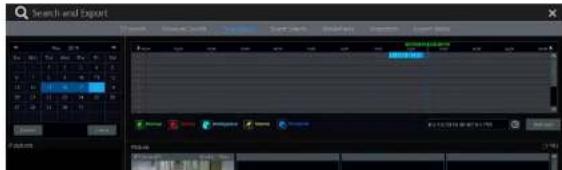
① Click Start→Search and Export→Time Search to go to the "Time Search" tab as shown below.
② Click on the bottom of the interface to add playback camera. A maximum of 16 cameras can be added for playback. Click "Modify" on the top right corner of the camera window to change the camera and click "Clear" to remove the camera.
Click the camera window to play the record in the small playback box on the left side of the interface. You can set the date on the top left of the interface, check the event type as required and click the time scale or click under the time scale to set the time. The camera window will play the record according to the time and event type you set.
Drag the color blocks on the time scale to select the record data (or click "Set Backup Time" button on the bottom left corner of the interface to set the backup start time and end time) and then click "Export" button for record backup. Click "Playback" button to play the record in the playback interface.
text_image
Search and Export Track Scene 1 Scene 2 Scene 3 Scene 4 Scene 5 Scene 6 Scene 7 Scene 8 Scene 9 Scene 10 Scene 11 Scene 12 Scene 13 Scene 14 Scene 15 Scene 16 Scene 17 Scene 18 Scene 19 Scene 20 Scene 21 Scene 22 Scene 23 Scene 24 Scene 25 Scene 26 Scene 27 Scene 28 Scene 29 Scene 30 Scene 31 Scene 32 Scene 33 Scene 34 Scene 35 Scene 36 Scene 37 Scene 38 Scene 39 Scene 40 Scene 41 Scene 42 Scene 43 Scene 44 Scene 45 Scene 46 Scene 47 Scene 48 Scene 49 Scene 50 Scene 51 Scene 52 Scene 53 Scene 54 Scene 55 Scene 56 Scene 57 Scene 58 Scene 59 Scene 60 Scene 61 Scene 62 Scene 63 Scene 64 Scene 65 Scene 66 Scene 67 Scene 68 Scene 69 Scene 70 Scene 71 Scene 72 Scene 73 Scene 74 Scene 75 Scene 76 Scene 77 Scene 78 Scene 79 Scene 80 Scene 81 Scene 82 Scene 83 Scene 84 Scene 85 Scene 86 Scene 87 Scene 88 Scene 89 Scene 90 Scene 91 Scene 92 Scene 93 Scene 94 Scene 95 Scene 96 Scene 97 Scene 98 Scene 99 Scene 100Playback & Backup
NVR User Manual

text_image
Search and Export File Edit View Insert Tools Help Tools Remove Settings Help Tools Help Tools Help Tools Help Tools Help Tools Help Tools Help Tools Help Tools Help Tools Help Tools Help Tools Help Tools Help Tools Help Tools Help Tools Help Tools Help Tools Help Tools Help Tools Help Tools Help Tools Help Tools Help Tools Help Tools Help Tools Help Tools Help Tools Help Tools Help Tools Help Tools Help Tools Help Tools Help Tools Help Tools Help Tools Help Tools Help Tools Help Tools Help Tools Help Tools Help Tools Help Tools Help Tools Help Tools Help Tools Help Tools Help Tools Help Tools Help Tools Help Tools Help Tots 1. 2. 3. 4. 5. 6. 7. 8. 9. 10. 11. 12. 13. 14. 15. 16. 17. 18. 19. 20. 21. 22. 23. 24. 25. 26. 27. 28. 29. 30. 31. 32. 33. 34. 35. 36. 37. 38. 39. 40. 41. 42. 43. 44. 45. 46. 47. 48. 49. 50. 51. 52. 53. 54. 55. 56. 57. 58. 59. 60. 61. 62. 63. 64. 65. 66. 67. 68. 69. 70. 71. 72. 73. 74. 75. 76. 77. 78. 79. 80. 81. 82. 83. 84. 85. 86. 87. 88. 89. 90. 91. 92. 93. 94. 95. 96. 97. 98. 99. 100. 2. 3. 4. 5. 6. 7. 8. 9. 10. 11. 12. 13. 14. 15. 16. 17. 18. 19. 20. 21. 22. 23. 24. 25. 26. 27. 28. -100% 3. -100% -100% -100% -100% -100% -100% -100% -100% -100% -100% -100% -100% -100% -100% -100% -100% -100% -100% -100% -100% -100% (See Page: F:\T\B\M) Import Export Help Help Tools Help Tools Help Tools Help Tools Help Tools Help Tools Help Tools Help Tools Help Tools Help Tools Help Tools Help Tools Help Tools Help Tools Help Tools Help Tools Help Tools Help Tools Help Tools Help Tools Help Tools Help Tools Help Tools Help Tools Help Tools Help Tools Help Tools Help Tools Help Tools Help Tools Help Tools Help Tools Help Tools Help Tools Help Tools Help Tools Help Tools Help Tools Help Tools Help Tools Help Tools Help Tools Help Tools Help Tools Help Tools Help Tools Help Tools Help Tools Help Tools Help Tools help tools help tools help tools help tools help tools help tools help tools help tools help tools help tools help tools help tools help tools help tools help tools help tools help tools help tools help tools help tools help tools help tools help tools help tools help tools help tools help tools help tools help tools help tools help tools help tools help tools help tools help tools help tools help tools help tools help tools help tools help tools help tools help tools help tools help tools help tools help tools help tools help tools help tools help teams help teams help teams help teams help teams help teams help teams help teams help teams help teams help teams help teams help teams help teams help teams help teams help teams help teams help teams help teams help teams help teams help teams help teams help teams help teams help teams help teams help teams help teams help teams help teams help teams help teams help teams help teams help teams help teams help teams help teams help teams help teams help teams help teams help teams help teams help teams help teams help teams help teams help groups help groups help groups help groups help groups help groups help groups help groups help groups help groups help groups help groups help groups help groups help groups help groups help groups help groups help groups help groups help groups help groups help groups help groups help groups help groups help groups help groups help groups help groups help groups help groups help groups help groups help groups help groups help groups help groups help groups help groups help groups help groups help groups help groups help groups help groups help groups help groups help groups help groups help Groups Help Help Help Help Help Help Help Help Help Help Help Help Help Help Help Help Help Help Help Help Help Help Help Help Help Help Help Help Help Help Help Help Help Help Help Help Help Help Help Help Help Help Help Help Help Help Help Help Help Help Expenses & Other Effects & Other Effects & Other Effects & Other Effects & Other Effects & Other Effects & Other Effects & Other Effects & Other Effects & Other Effects & Other Effects & Other Effects & Other Effects & Other Effects & Other Effects & Other Effects & Other Effects & Other Effects & Other Effects & Other Effects & Other Effects & Other Effects & Other Effects & Other Effects & Other Effects & Other Effects & Other Effects & Other Effects & Other Effects & Other Effects & Other Effects & Other Effects & Other Effects & Other Effects & Help② Check the event type in the interface as required.
③ Click to set the start time and end time on the top left of the interface.
④ Check cameras on the left side of the interface or check "All" to select all the cameras and then click to search the record. The searched record will be displayed in the list.
Click In the list to play back the record in the popup window. Click to back up one record data or check multiple record data in the list and then click "Backup" button for record batch backup.
⑥ Select one record data in the list and then click "Playback" button to play the record in the playback interface.
8.3.5 Bookmark Search
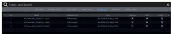
Only if you add the tags can you play the record by tag search. Click Start→Playback to go to the playback Interface and then click 📄 on the bottom of the camera window to add bookmarks when you want to mark the playback time point of the selected camera. Click Start→Search and Export→Bookmarks to go to "Bookmarks" tab.
text_image
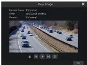
Search and Export No. Name Search Type Date Status Report Date Report Status Index Exhibit 1 # Canada, 20180116-1032 # Canada 到 01/29/16:55:37:50 ☑ 2 # Canada, 20180116-1034 # Canada 到 01/29/16:55:37:50 ☑ 3 # Canada, 20180116-1036 # Canada 到 01/29/16:55:37:50 ☑Click In the Interface to play the record. Click to edit the tag name. Click to delete the tag.
text_image
View Image Camera Name: P Camera Time: 10/27/2015 14:56:01 Creation: P Camera1 Edit8.3.7 View Export Status
Click Start→Search and Export→Export Status or click 📄 on the tool bar at the bottom of the playback interface to view the export status.
9 Alarm Management
9.1 Sensor Alarm
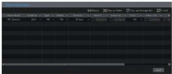
To complete the entire sensor alarm settings, you should enable the sensor alarm of each camera and then set up the alarm handling of each camera. ① Click Start→Settings→Alarm→Sensor Alarm to go to the following Interface.
text_image
Audio Name Speed: 500 Type Create Documents Record Support Paste Audio 9PC Sensor1 Shift 140 ON 30 Secs Background Background ON Background Audio② Select schedule and the alarm type (NO or NC) according to trigger type of the sensor.
③ Enable the sensor alarm of each camera.
④ Check the "Duration", "Record", "Snapshot", "Push", "Alarm-out" and "Preset" and enable or disable the "Buzzer", "Pop-up Video", "Pop-up Message Box" and "E-mail" as required.
⑤ Click "Apply" to save the settings.
The configuration steps of the above mentioned alarm linkages are as follows.
Duration: it refers to the interval time between the adjacent motion detections. For instance, if the duration time is set to 10 seconds, once the system detects a motion, it will go to alarm and would not detect any other motion (specific to camera) in 10 seconds. If there is another motion detected during this period, it will be considered as continuous movement; otherwise it will be considered as a single motion.
Record: check it and then the "Trigger Record" window will pop up automatically (you can also click "Configure" button to pop up the window). Select camera on the left side and then click ■ to set the camera as the trigger camera. Select trigger camera on the right side and then click
to cancel the trigger camera. Click "OK" button to save the settings. The trigger cameras will record automatically when the sensor alarm is triggered.
Snapshot: check it and then the "Trigger Snapshot" window will pop up automatically. Configure the trigger camera in the window. The trigger cameras will snap automatically when the sensor alarm is triggered.
Push: check it and choose NO or OFF. If it is ON, the system will send messages when the sensor alarm is triggered.
Alarm-out: check it and then the "Trigger Alarm-out" window will pop up automatically. Configure the trigger alarm-out in the window. The system

text_image
Camera Name ON 5 20 Seps IP Camera1 ON 5 20 Seps IP Camera2 ON 5 20 Seps IP Camera3 ON 5 20 Seps Duration: 200 Seps OK Cancel Preview View Current IP Camera4 Window ON Duration: 200 Seps Increasing Settings... Apply② Select the camera, enable the motion and set the sensitivity and duration of the camera. Sensitivity: the higher the value is, the more sensitive it is to motion. You should adjust the
value according to the practical conditions since the sensitivity is influenced by color and time (day or night).
Duration: It refers to the interval time between the adjacent motion detections. For instance, if the duration time is set to 10 seconds, once the system detects a motion, it will go to alarm and would not detect any other motion (specific to camera) in 10 seconds. If there is another motion detected during this period, it will be considered as continuous movement; otherwise it will be considered as a single motion.
Drag the camera image to set the motion area. Click "All" to set the whole camera image as the motion area. Click "Reverse" to swap the motion area and the non-motion area. Click "Clear" to clear all the motion areas.
④ Click "Apply" to save the settings. Click "Processing Mode" to go to the alarm handling configuration interface of the motion alarm.
9.2.2 Motion Alarm Handling Configuration
① Click Start→Settings→Alarm→Motion Alarm to go to the following interface.

text_image
Current Current Current Current Current Current Current Current Current Current Current Current Current Current Current Current Current Current Current Current Current Current Current Current Current Current Current Current Current Current Current Current Current Current Current Current Current Current Current Current Current Current Current Current Current Current Current Current Current Current CurrentAlarm Management
NVR User Manual
© Click "Processing Mode" to go to the alarm handling configuration interface of object detection.

text_image
Aeroposition Cinema Top view In view Object Detection Distant Type Area Area name Cinema Name IP重映片 OFF Abandoned Object 1 IP重映片 OFF Abandoned Object 1 IP重映片 OFF Abandoned Object 1 Clear area Clear Preview to Play OKObject Detection Alarm Handling Configuration:
① Click Start→Settings→Alarm→Intelligence Alarm→Object Detection to go to the following interface.
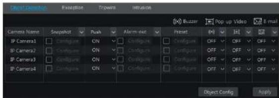
text_image
Camera Name Snapshot Push Alarm-out Preset OFF OFF OFF IP Camera1 Configure ON Configure Configure Configure OFF OFF OFF IP Camera2 Configure ON Configure Configure Configure OFF OFF OFF IP Camera3 Configure ON Configure Configure Configure OFF OFF OFF IP Camera4 Configure ON Configure Configure OFF OFF OFF Object Config Apply② Enable or disable "Snapshot", "Push", "Alarm-out", "Preset", "Buzzer", "Pop-up Video" and "E-mail". The alarm handling setting of object detection alarm is similar to that of the sensor alarm (see 9.1 Sensor Alarm for details).

text_image
Scene Change Video Buried Video Color Curr Sensitivity Context Name IP通道1 OFF V OFF V OFF V IF IP通道2 OFF V OFF V OFF V IP通道3 OFF V OFF V OFF V IF Preview to Note OK② Select the camera and enable the relevant detection as needed.
Scene Change: Alarms will be triggered if the scene of the monitor video has changed.
Video Blurred: Alarms will be triggered if the video becomes blurry.
Video Color Cast: Alarms will be triggered if the video becomes obscured.
③ Set the sensitivity of the exception detection.
④ Click "Apply" to save the settings.
⑤ Click "Processing Mode" to go to the alarm handling configuration interface of exception detection.
Exception Alarm Handling Configuration:
① Click Start→Settings→Alarm→Intelligence Alarm→Exception to go to the interface.
| Object Detection | Excess | Triplets | Invasion | |||||
| Camera Name | Snapshot | Push | Alarm-out | Preset | OFF | OFF | OFF | OFF |
| IP Camera1 | Configure | ON | Configure | Configure | OFF | OFF | OFF | OFF |
| IP Camera2 | Configure | ON | Configure | Configure | OFF | OFF | OFF | OFF |
| IP Camera3 | Configure | ON | Configure | Configure | OFF | OFF | OFF | OFF |
| IP Camera4 | Configure | ON | Configure | Configure | OFF | OFF | OFF | OFF |
Alarm Management
NVR User Manual
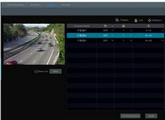
text_image
Open Direction Direction Show Follow View Timeline Line Direction Camera Name P: 01 P: 02 P: 03 P: 04 P: 05 P: 06 P: 07 P: 08 P: 09 P: 10 P: 11 P: 12 P: 13 P: 14 P: 15 P: 16 P: 17 P: 18 P: 19 P: 20 P: 21 P: 22 P: 23 P: 24 P: 25 P: 26 P: 27 P: 28 P: 29 P: 30 P: 31 P: 32 P: 33 P: 34 P: 35 P: 36 P: 37 P: 38 P: 39 P: 40 P: 41 P: 42 P: 43 P: 44 P: 45 P: 46 P: 47 P: 48 P: 49 P: 50 P: 51 P: 52 P: 53 P: 54 P: 55 P: 56 P: 57 P: 58 P: 59 P: 60 P: 61 P: 62 P: 63 P: 64 P: 65 P: 66 P: 67 P: 68 P: 69 P: 70 P: 71 P: 72 P: 73 P: 74 P: 75 P: 76 P: 77 P: 78 P: 79 P: 80 P: 81 P: 82 P: 83 P: 84 P: 85 P: 86 P: 87 P: 88 P: 89 P: 90 P: 91 P: 92 P: 93 P: 94 P: 95 P: 96 P: 97 P: 98 P: 99 Close Line Close② Select the camera, enable the line crossing detection.
③ Select the direction.
Direction: A<->B, A->B and A<-B optional. It is the crossing direction of the intruder who crosses over the alert line.
A<->B: the alarm triggers when the intruder crosses over the alert line from B to A or from A to B.
A->B: the alarm triggers when the intruder crosses over the alert line from A to B.
A<-B: the alarm triggers when the intruder crosses over the alert line from B to A.
④ Draw line. Refer to the interface as shown above. Check "Draw line" and then drag the mouse in the image to draw an alert line. Uncheck the "Draw line" if you finish the drawing. Click the "Clear" to delete the alert line.
⑤ Click "Apply" to save the settings.
© Click "Processing Mode" to go to the alarm handling configuration interface of line crossing detection.
Tripwire Alarm Handling Configuration:
① Click Start→Settings→Alarm→Intelligence Alarm→Tripwire to go to the following interface.

Alarm Management
NVR User Manual
⑤ Click "Apply" to save the settings.
© Click "Processing Mode" to go to the alarm handling configuration interface of intrusion detection.
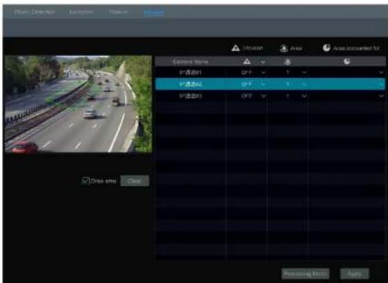
text_image
Drive Detection Functions Types Air Air Prescued for Camera Name IP 通道B1 OFF 1 IP 通道C2 OFF 1 IP 通道D3 OFF 1 Auto Drive time Clear Processing Unit ApplyIntrusion Detection Alarm Handling Configuration:
① Click Start→Settings→Alarm→Intelligence Alarm→Intrusion to go to the following interface.

text_image
Object Detection Exception Traverse Camera Name Snapshot Push Alarm-out Preset Off OFF OFF IP Camera1 Configure ON Configure Configure OFF OFF OFF IP Camera2 Configure ON Configure Configure OFF OFF OFF IP Camera3 Configure ON Configure Configure OFF OFF OFF IP Camera4 Configure ON Configure Configure OFF OFF OFF Inclusion Config ApplyAlarm Management
NVR User Manual
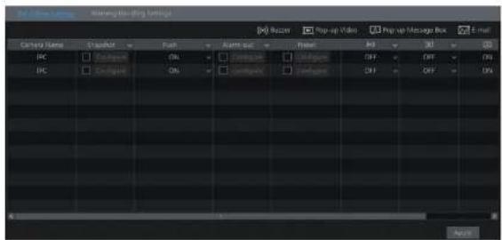
text_image
File Edit Settings Name: New York Media Category Name Signal Font Audio sub Fillet Add Add Add Add Add Add Add Add Add Add Add Add Add Add Add Add Add Add Add Add Add Add Add Add Add Add Add Add Add Add Add Add Add Add Add Add Add Add Add Add Add Add Add Add Add Add Add Add Add Add Edit9.4.2 Warning Handling Settings
① Click Start→Settings→Alarm→Exception→Warning Handling Settings to go to the interface as shown below.
② Enable or disable "Push", "Alarm-out", "Buzzer", "Pop-up Message Box" and "E-mail". The exception handling settings are similar to that of the sensor alarm (see 9.1 Sensor Alarm for details).
③ Click "Apply" to save the settings.
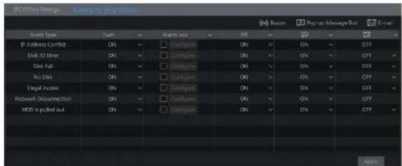
text_image
IEC Office Settings - Sourcing by ping 1000 Event Type: Event IP Address Correct ON Event Type: Event Event List ON Event List ON Event Address ON Event Address ON Event Address ON Event Address ON Event Address ON Event Address ON Event Address ON Event Address ON Event Address ON Event Address ON Event Address ON Event Address ON Event Address ON Event Address ON Event Address ON Event Address ON Event Address ON Event Address ON Event Address ON Event Address ON Event Address ON Event Address ON Event Address ON Event Address ON Event Address ON Event Website: http://www.iec.com/ IEC is pulled out ON IEC is pulled out IEC is pulled out IEC is pulled out IEC is pulled out IEC is pulled out IEC is pulled out IEC is pulled out IEC is pulled out IEC is pulled out IEC is pulled out IEC is pulled out IEC is pulled out IEC is pulled out IEC is pulled out IEC is pulled out IEC is pulled out IEC is pulled out IEC in the following: IEC in the following: IEC in the following: IEC in the following: IEC in the following: IEC in the following: IEC in the following: IEC in the following: IEC in the following: IEC in the following: IEC in the following: IEC in the following: IEC in the following: IEC in the following: IEC in the following: IEC in the following: IEC in the following: IEC in The following: IEC in The following: IEC in The following: IEC in The following: IEC in The following: IEC in The following: IEC in The following: IEC in The following: IEC in The following: IEC in The following: IEC in The following: IEC in The following: IEC in The following: IEC in The following: IEC in The following: IEC in The following: IEC in The following: IEc In the following: IEc In the following: IEc In the following: IEc In the following: IEc In the following: IEc In the following: IEc In the following: IEc In the following: IEc In the following: IEc In the following: IEc In the following: IEc In the following: IEc In the following: IEc In the following: IEc In the following: IEc In the following: IEc In the following: IEe In the following: IEe In the following: IEe In the following: IEe In the following: IEe In the following: IEe In the following: IEe In the following: IEe In the following: IEe In the following: IEe In the following: IEe In the following: IEe In the following: IEe In the following: IEe In the following: IEe In the following: IEe In the following: IEe In the following:9.5 Alarm Event Notification
9.5.1 Alarm-out
① Click Start→Settings→Alarm→Event Notification to go to the following interface.
Alarm Management
NVR User Manual
and the pop-up message box. Click "Apply" to save the settings.

text_image
Pop-up Video Duration 5 Secs Pop-up Message Box Duration 10 Secs Apply9.5.4 Buzzer
Click Start→Settings→Alarm→Event Notification→Buzzer to go to the buzzer configuration interface. Set the delay time of the buzzer and then click "Apply" to save the setting. You can click "Test" to test the buzzer.
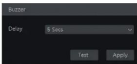
9.5.5 Push Message
Click Start→Settings→Alarm→Event Notification→Push Message to go to the interface as shown below. Check "Enable" and then click "Apply" button to save the settings. If Push Server is online, it will push messages to the mobile clients.
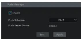
0.5 Manual Alarm
Alarm Management
NVR User Manual

text_image
Suzzer Alarm-in Alarm-out Motion Intelligence Exception Normal Normal Normal Normal Exception ExitClick "Clear" button to stop the buzzer when the buzzer alarm happens. Click 🤒 to view the detail information as shown below.
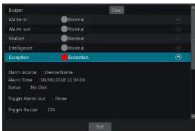
text_image
Blazer Alarm-In Normal Alarm-out Normal Motion Normal Intelligence Normal Exception Exception Alarm Source : Device Name Alarm Time : 06/05/2018 11:34:06 Status : No Disk Trigger Alarm out : None Trigger Blazer ON ExitIf the exception information is more than one page, you can enter the number in the box and then click to jump to the specified page. Click / to view the exception alarm information in the previous/next page. Click to play the alarm record.
10 Account & Permission Management
10.1 Account Management
Click Start→Settings→Account and Authority→Account→Edit User to go to the interface as shown below.
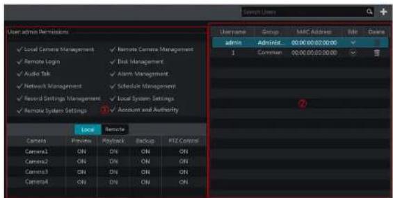
text_image
User admin Remission Local Camera Management Remote Camera Management Remote Login Risk Management Audio Talk Alarm Management Network Management Schedule Management Record Settings Management Local System Settings Remote System Settings Account and Authority Local Remote Camera Process Retryback Backup PZE Control Camera1 ON ON ON ON Camera2 ON ON ON Camera3 ON ON ON Camera4 ON ON ON Username Group MAC Address File Down Admnx Advisor 00:00:00:00:00 1 Common 00:00:00:00:00 ②Area ① displays the user permissions. Area ② displays the user list. Click the user in the list to display its user permissions in area ①.
There are three default permission groups ("Administrator", "Advanced" and "Common") available when adding accounts. You can manually add new permission group (see 10.3.1 Add Permission Group for details).
Only admin and the users that have the "Account and Authority" permission can manage the system's accounts. Group "Administrator" owns all the permissions displayed in area ① except "Account and Authority" and its permissions cannot be changed while the permissions of "Advanced" and "Common" can be changed.
10.1.1 Add User
① Click Start→Settings→Account and Authority→Account→Add User or click + beside the search box to pop up the window as shown below.
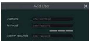
text_image
Add User Username: Other Username Password: Other Password Confirm Password: Other PasswordAccount & Permission Management
NVR User Manual
Edit Security Question
You can set password security only for admin. Click "Edit Security Question" and then set questions and answers in the popup window. If you forget the password for admin, please refer to Q4 in Appendix A FAQ for details. The passwords of other users can be recovered by admin or the users that have the "Account and Authority" permission.
Modify Password
Only the password of admin can be modified. Click "Modify Password" to pop up a window. Enter the current password and then set new password. Click "OK" to save the settings.
Modify Pattern Lock
Some models may not support this function. Click "Modify Pattern Lock" to pop up a window.

text_image
Modify Pattern Lock Current Password Pattern Lock Enable Edit OK CancelEnter current password and then check "Enable" to input pattern lock.

➢ Recover Password
Click "Recover Password" to reset the password to 123456.
to log out the system.
10.3 Permission Management
10.3.1 Add Permission Group
Click Start→Settings→Account and Authority→Account→Edit Permission Group to go to the interface as shown below.
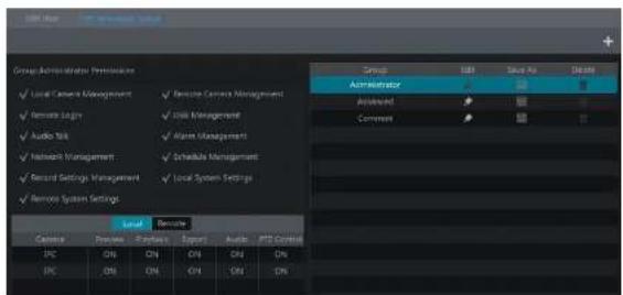
text_image
Group Administration Preferences ✓ Local Control Management ✓ Remote Control Management ✓ Remote Logis ✓ Disk Management ✓ Audio Bits ✓ Main Management ✓ Network Management ✓ Endable Management ✓ Second Settings Management ✓ Local System Settings ✓ Remote System Settings Local Devote Control Device Project Export Audio PTS Control IPC ON ON ON ON ON IPC ON ON ON ON ONClick + to add permission group. Set the group name, check the permissions as needed and then set the "Local" and "Remote" permissions. Click "Add" to save the settings.
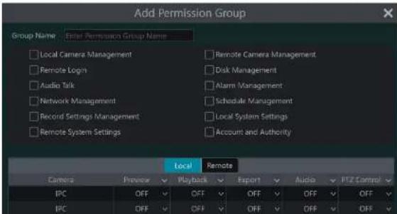
text_image
Add Permission Group Group Name Enter Permission Group Name Local Camera Management Remote Login Audio Talk Network Management Record Settings Management Remote System Settings Remote Camera Management Disk Management Alarm Management Schedule Management Local System Settings Account and Authority Local Remote Camera Preview Playback Export Audio PTZ Control IPC OFF OFF OFF OFF OFF OFF IPC OFF OFF OFF OFF OFFAccount & Permission Management
NVR User Manual
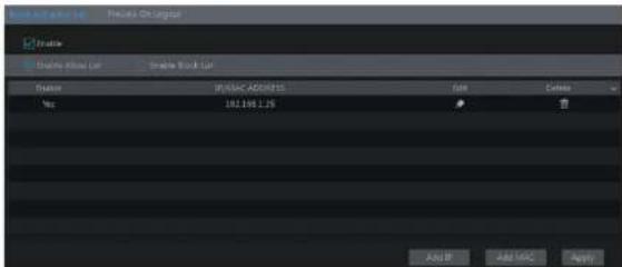
text_image
File Edit View List Prelicise On Imagelet Create Create Info List Create Book List Name: IP:000C.ADEGNTS Size Delete Win: 181.158 LJS ADD IP ADD MISC Apply② Check "Enable" and then choose "Enable Allow List" or "Enable Block List" (the PC client of which the IP address is in the allow list can access NVR remotely while the PC client in the block list cannot).
③ Add IP/IP segment/MAC. Click "Add IP" or "Add MAC" button and then check "Enable" in the popup window (only if you check it can the IP/IP segment/MAC you add be effective). Enter the IP/IP segment/MAC and then click "OK" button. In the above interface, click to edit IP/IP segment/MAC, click to delete it. Click "Apply" to save the settings.
10.5 Preview On Logout
Click Start→Settings→Account and Authority→Security→Preview On Logout to go to the following interface.
Set a camera and then enable or disable the preview permission on logout as required. If a camera's preview permission on logout is "ON", you can view the live image of the camera when the system is logged out, or the live image of the camera cannot be seen when logged out.

text_image
Camera Name Camera1 Camera2 Camera3 Camera4 Camera5 Camera6 Camera7 Camera8 Camera9 Camera10 Camera11 Camera12 Camera13 Camera14 Camera15 Camera16 Camera17 Camera18 Camera19 Camera20 Camera21 Camera22 Camera23 Camera24 Camera25 Camera26 Camera27 Camera28 Camera29 Camera30 Camera31 Camera32 Camera33 Camera34 Camera35 Camera36 Camera37 Camera38 Camera39 Camera40 Camera41 Camera42 Camera43 Camera44 Camera45 Camera46 Camera47 Camera48 Camera49 Camera50 Camera51 Camera52 Camera53 Camera54 Camera55 Camera56 Camera57 Camera58 Camera59 Camera60 Camera61 Camera62 Camera63 Camera64 Camera65 Camera66 Camera67 Camera68 Camera69 Camera70 Camera71 Camera72 Camera73 Camera74 Camera75 Camera76 Camera77 Camera78 Camera79 Camera80 Camera81 Camera82 Camera83 Camera84 Camera85 Camera86 Camera87 Camera88 Camera89 Camera90 Camera91 Camera92 Camera93 Camera94 Camera95 Camera96 Camera97 Camera98 Camera99 Camera10011 Device Management
11.1 Network Configuration
11.1.1 TCP/IP Configuration
Click Start→Settings→Network→TCP/IP to go to the following interface. Check "Obtain an IPv4 address automatically", "Obtain an IPv6 address automatically" and "Obtain DNS automatically" to get the network addresses automatically, or manually enter the network addresses. You can modify the MTU value according to the network condition (MTU, Maximum Transmission Unit, can be modified according to network condition for higher network transmission efficiency). Click "Apply" to save the settings.

text_image
User and User Size: 100 Size: 100 Size: 100 Size: 100 Size: 100 Size: 100 Size: 100 Size: 100 Size: 100 Size: 100 Size: 100 Size: 100 Size: 100 Size: 100 Size: 100 Output: Output: Output: Output:Note:
- Internal Ethernet Port
if you use the NVR with the PoE network ports, click "Internal Ethernet Port" to go to the following interface.
The internal ethernet port is the port which connects all the PoE ports with the NVR system. The PoE ports are available if the internal ethernet port is online; if it is offline, all the PoE ports will be unavailable, may be the internal ethernet port is broken. The network addresses of the internal ethernet port can be changed to make the port in the same network segment with the IP cameras which directly connect to the PoE ports of the NVR (It is not recommended to change the network addresses of the internal ethernet port).

text_image
IP Address Settings Ethernet Port & (Online) Internal Ethernet Port Address Address 10 115 121 1 Address Socket Mask 212 0 3 5 Stack Length Preferred DHS Alternate DHS ApplyDevice Management
NVR User Manual
stream protocol, you can view the live images synchronously. The default RTSP port is 554 and it can be changed as required.
Note: The HTTP port and server port of the NVR should be mapped to the router before you access the NVR via WAN.
11.1.3 PPPoE Configuration
Click Start→Settings→Network→PPPoE to go to the interface as shown below. Check "Enable" in "PPPoE Settings" and then enter the username and password obtained from the dealer. Click "Apply" to save the settings.

text_image
PPPoF Settings Enable Username xxx Password ****** Apply11.1.4 DDNS Configuration
The DDNS is used to control the dynamic IP address through domain name. Speco Technologies provides free DDNS service with US-based servers. You can access to the NVR easily if the DDNS is enabled and configured. Click Start→Settings→Network→DDNS to go to the Interface as shown below. The default DDNS type will be "specoddns.net". The default domain name will be shown, you can use this for your domain name or enter your own. If invalid or taken, please select another domain name. Click on test to check if ok. If so, you may now go to [your domain name].specoddns.net with Internet Explorer and access your recorder remotely.
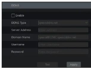
text_image
DDNS Enable DDNS Type specodds.net Server Address Enter UserName Domain Name specDB.DAC specodds.net Username Enter UserName Password Enter Password Text Apply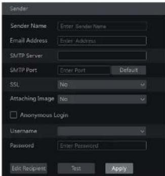
text_image
Sender Sender Name: Enter Sender Name Email Address: Enter Address SMTP Server SMTP Port: Enter Port Default SSL: No Attaching Image: No Anonymous Login Username Password: Enter Password Edit Recipient Test ApplyClick "Edit Recipient" to go to the following interface.
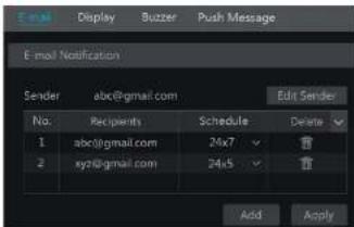
text_image
E-mail Notification Sender abc@gmail.com Edit Sender No. Recipients Schedule Delete 1 abc@gmail.com 24x7 2 xyz@gmail.com 24x5 Add ApplyClick "Add" and then enter the recipient's e-mail address and select the schedule (if a schedule is selected, the system will send the alarm email and the recipient will receive it only in the selected schedule time) in the popup window. Click "Add" in the window to add the recipient. You can also change the recipient's receiving schedule by clicking In the "Schedule" column. Click to delete the recipient in the list. Click "Apply" to save the settings. Click "Edit Sender" to go to the e-mail configuration interface of the sender.
11.1.6 UPnP Configuration

text_image
UFP Enable Map Type Manual Port Type External Port External IP Address Port UFP Status Edit HTTP Port 80 183.17.254.19 Valid UPnP HTTPS Port 443 183.17.254.19 Valid UPnP Server Port 6036 183.17.254.19 Valid UPnP RTSP Port 554 183.17.254.19 Valid UPnP Refresh Apply11.1.7 NAT Configuration
Click Start→Settings→Network→NAT to go to the interface for NAT configuration and check "Enable". Click "Apply" to save the settings and make note of the QR code number under the QR code. Via Internet Explorer, go to connect.specotech.cloud, input the QR code number, your username and password to login. You can also scan the QRCode through mobile client which is installed in the mobile phone or PAD to log in the mobile client instantly.
11.1.8 View Network Status
Click Start→Settings→Network→Network Status to view the network status or click 📄 on the tool bar at the bottom of the live view interface to view network status conveniently.
11.2 Basic Configuration
11.2.1 General Configuration
Click Start→Settings→System→Basic→General Settings to go to the following Interface. Set the device name, device No., language, video format and main output. Enable or disable wizard, "Log In Automatically", "Log Out Automatically" (if checked, you can set the wait time), "App Live Self-Adaption" and "Dwell Automatically" (if checked, you can set the wait time). Click "Apply" to save the settings.

text_image
General Settings Device Name Device Name Device No. 1 Language English Video Format NTSC Main Output 128x1024Device Management
NVR User Manual
You can manually set the system time or synchronize system time with network through NTP.
Manual: select "Manual" in the "Synchronous" option and then click after the "System Time" option to set the system time.
NTP: select "NTP" in the "Synchronous" option and then enter the NTP server.

text_image
Date and Time System Time 11/03/2015 17:02:13 Date Format Month/Day/Year Time Format 24-Hour Sync Time With Network Synchronous Manual NTP Server time.windows.com Time Zone / DST Time Zone GMT+08 Beijing, Hong Kong, 5 DST Create Apply11.3 Factory Default
Click Start→Settings→System→Maintenance→Factory Default and then click "Reset to factory default" button in the Interface to reset to the factory default settings(check "Reset retain Network Configuration" to retain the network settings).
Note: Resetting to the factory default settings will not change time zone.
11.4 Device Software Upgrade
- Upgrade
You can click Start→Settings→System→Information→Basic to view MCU, kernel version and firmware version and so on. Before upgrade, please get the upgrade file from your dealer.
① Copy the upgrade software into the USB storage device.
② Insert the USB storage device into the USB interface of the NVR.
③ Click Start→Settings→System→Maintenance→Upgrade to go to "Upgrade" interface. Select the USB device in "Device Name" option and go to the path where the upgrade software exists. Select the upgrade software and then click "Upgrade". The system may automatically restart during upgrading. Please wait for a while and do not power off the NVR during upgrading.
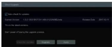
text_image
Auto-check for updates Current Version 1.3.2.10/2017/2/11 NBL U (22A/MD) beta This is the latest version. Don't power of during the upgrade process. Direct for Updates 工程建设 Apply11.5 Backup and Restore
You can back up the configuration file of the NVR by exporting the file to other storage devices; you can recover the configuration to other NVRs which are of the same model with the NVR by importing the configuration file to other NVRs for time saving. Insert the USB storage device into the USB interface of the NVR and then click Start→Settings→System→Maintenance→Backup and Restore to go to the interface.
- Backup
Select the USB device in "Device Name" option; go to the path where you want to store the configuration backup file and then click "Backup" button; finally click "OK" button in the popup window.
- Recover
Select the USB device in "Device Name" option; find the configuration backup file and then click "Recover" button; finally click "OK" button in the popup window.
11.6 Restart Automatically
You can set the automatic restart time for the NVR to maintain it regularly. Click Start→Settings→System→Maintenance→Auto Maintenance to go to the interface as shown below. Enable auto maintenance, set the interval days and point of time and then click "Apply" to save the settings. The NVR will restart automatically at the pointed time every interval days.
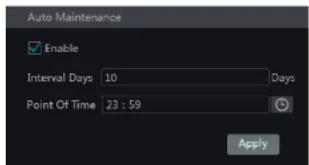
text_image
Auto Maintenance Enable Interval Days 10 Days Point Of Time 23 : 59 ApplyDevice Management
NVR User Manual
Choose the log file in the list and then click "Export" button to export the log file. Click on the "Content" title bar to pop up a menu list. Check contents in the menu list and then the log list will show the checked log contents only. Click to play the video log.
11.8 View System Information
Click Start→Settings→System→Information and then click the corresponding menu to view the "Basic", "Camera Status", "Alarm Status", "Record Status", "Network Status" and "Disk" information of the system.
12 Remote Surveillance
12.1 Mobile Client Surveillance
① Enable NAT in the NVR. Refer to 11.1.7 NAT Configuration for details.
② Scan the QRCode through the Speco Blue App available for IOS and Android to easily and securely view your cameras.
⑤ Run the mobile client, go to the "Add Device" interface and then click → to scan the QRCode of the NVR (Go to Start→Settings→System→Information→Basic to view the QRCode of the NVR).
④ After scanning the QRCode successfully, enter the login password to log in mobile client.

text_image
Add device My device Pick name User Password Play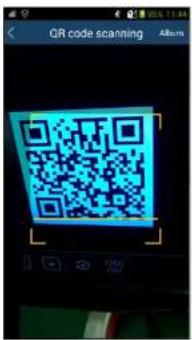
text_image
QR code scanning AlbumMobile viewing is also available on our SecureGuard client app.
12.2 Web LAN Access
① Click Start→Settings→Network→TCP/IP to go to the "TCP/IP" Interface. Set the IP address, subnet mask, gateway, preferred DNS and alternate DNS of the NVR.
② Open the web browser on your computer, enter the IP address of the NVR in the address bar and then press enter to go to the login interface as shown below. You can change the display language on the top right corner of the login interface. Enter the username and password of the NVR in the interface and then click "Login" to go to the live view interface.
Remote Surveillance
NVR User Manual
② Click Start→Settings→Network→NAT to go to the interface for NAT configuration and check "Enable". Click "Apply" to save the settings and make note of the QR code number under the QR code. Via Internet Explorer, go to connect.specotech.cloud, Input the QR code number, your username and password to login.

text_image
speco technologies Giving You More. QR code number Enter Your Username Enter Your Password LoginPPPoE Access
① Click Start→Settings→Network→PPPoE to go to the "PPPoE" interface. Check "Enable" in the "PPPoE settings" and then enter the username and password you get from your ISP. Click "Apply" to save the settings.
② Click Start→Settings→Network→Network Status to view the IP address of the NVR.
③ Open the web browser on your computer, enter the IP address of the NVR like http://210.21.229.138 in the address bar and then press enter to go to the login Interface. Enter the username and password of the NVR in the interface and then click "Login" to go to the live view Interface.
Router Access
① Click Start→Settings→Network→TCP/IP to go to the "TCP/IP" interface. Set the IP address, subnet mask, gateway, preferred DNS and alternate DNS of the NVR.
Set the HTTP port (it is suggested to modify the HTTP port because the default HTTP port 80 might be taken up) and enable UPnP function in both the NVR and the router. If the UPnP function is not available in the router, you need to forward the LAN IP address, HTTP port and server port of the NVR to the router. Port mapping settings may be different in different routers, so please refer to the user manual of the router for details.
① Get the WAN IP address of the NVR from the router. Open the web browser on your computer, enter the WAN IP address plus HTTP port like http://116.30.18.215-100 in the address bar and then press enter to go to the login interface. Enter the username and password of the NVR in the interface and then click "Login" to go to the live view interface.
Note: If the WAN IP address is a dynamic IP address, it is necessary for you to use the domain name to access the NVR. Click Start>Settings→Network→DDNS to set DDNS (see 11.1.4 DDNS Configuration for details). By using DDNS function you can use the domain name plus HTTP port like http://sunshine.dsvdydns.com:100 to access the NVR via internet.
12.4 Web Remote Control
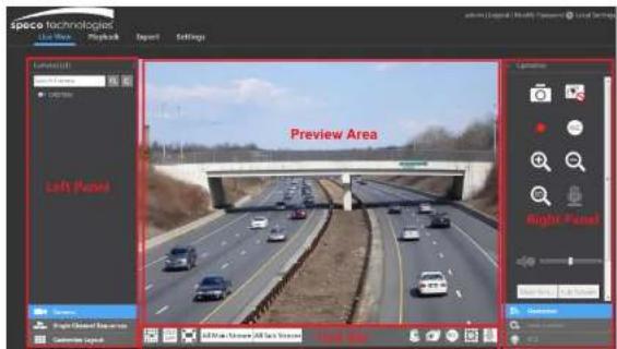
text_image
speco technologies Live State Playback Export Settings Left Panel Preview Area Right Panel Left Panel Left Panel Right Panel Left Panel Left PanelStart Preview
Select a window in the preview area and then click one online camera on the left panel to preview the camera in the window. You can click 📄 in the tool bar to view all the cameras.
> Left Panel Introduction
Click < on the left panel to hide the panel and click > to show the panel. You can view all the added cameras and groups on the left panel.
• View Camera
Click Camera to view the cameras. You can view the number of all the added cameras and the online cameras. For instance, the left number 3 in Camera (3/4) on the left panel stands for the number of online cameras; the right number 4 stands for the number of all the added cameras. Enter the camera name In the search box and then click to search the camera. Click to refresh the camera list.
• View Group
Click Single Channel Sequences to view the groups. All groups and all cameras in the group can be shown in the left panel.
• View Scheme
Click Customize Layout to view the scheme (or planning). All schemes can be shown in the left panel. Double click the scheme name to invoke it quickly
➢ Tool Bar Introduction
Click 📄 Lens Control to go to "Lens Control". Click 📄 Operation to go to "Operation" panel.

text_image
Operation Main Struts: 1.4x 51.0 px Resolution: 2920x2080 FPS: 30 Main Rotational: 320-80fps Apply Operator Use Control PTZ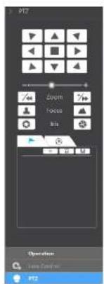
text_image
PTZ Zoom Focus Blue Operation Name Control PTZClick one camera window in the preview area and then click Main Stream to set the camera's live view stream and record stream to main stream in manual record mode; click Sub-stream to set the camera's live view stream and record stream to sub stream. In sub stream tab, set the resolution, FPS and bitrate and then click "Apply" to save the settings.
Operation panel Introduction:
| Button Meaning | |
| Click it to take snapshots. | |
| Click it to start recording to computer; click it again to stop recording. | |
| Click it to zoom in the image of the camera and then drag the mouse on the camera image to view the hidden area. | |
| Click it to zoom out the image of the camera. | |
| The 3D zoom in function is designed for P.T.Z. Click the button and then drag the image to zoom in or zoom out the image; click the image on different areas to view the image of the camera one-directionally. | |
Remote Surveillance
NVR User Manual
| Button Meaning | |
| 5 | Click it to view the cruise list and then click the corresponding buttons in the list to start or stop the cruise. |
12.4.2 Remote Playback
Click "Playback" In the remote interface to go to the playback interface.
① Check the record event types and cameras on the left panel. Set the record date on the calendar beside the time scale.
② Click 9 to search the record data and then click ① or directly click the time scale to play the record.
The operation of the playback time scale is similar to that of the time scale in the main program of the NVR. Please refer to 8.2 Playback Interface Introduction for details.
Introduction of playback control buttons:
| Button Meaning | |
| Stop button. | |
| Rewind button. Click it to play video backward. | |
| Play button. Click it to play video forward. | |
| Pause button. | |
| Deceleration button. Click it to decrease the playing speed. | |
| Acceleration button. Click it to increase the playing speed. | |
| Previous frame button. it works only when the forward playing is paused in single screen mode. | |
| Next frame button. It works only when the forward playing is paused in single screen mode. | |
| Click to step backward 30s and click to step forward 30s. | |
| Backup start time button. Click the time scale and then click it to set the backup start time. | |
| Backup end time button. Click the time scale and then click it to set the backup end time. | |
| Export button. | |
| Backup tasks button. Click it to view the backup status. | |
| Event list button. Click it to view the event record of manual/schedule/sensor/motion. | |
12.4.3 Remote Export
Click "Export" In the remote Interface to go to the export Interface. You can export the record by event search or by time search.
Event Search
Appendix A FAQ
Q1. Why can't I find the HDD?
a. Please check the power and SATA data cables of the HDD to make sure they are well connected.
b. For some NVRs with the 1U or small 1U case, the power of the adapter may be not enough for operating them. Please use the power adaptor supplied along with the NVR.
c. Please make sure the HDDs are compatible with the NVR. See Appendix C Compatible Device List for details.
d. The HDD could have gone bad. Change a new one.
Q2. Why are there no images output in some or all of the camera windows?
a. Please make sure the resolutions of the cameras are supported by the NVR.
b. Please make sure the network cables of the IP camera and NVR are both connected properly and the network parameters are set correctly.
c. Please make sure the network and the switch both work normally.
Q3. The screen has no output after booting the NVR normally.
a. Please make sure the screen, HDMI or VGA cables are good and well connected.
b. Please make sure the screen supports the resolution of 1280*1024, 1920*1080 or 3840*2160 (4K*2K). The NVR cannot self-adapt to the screen of which the resolution is lower than 1280*1024, and then the screen will remind you that the screen resolution is not supported by the NVR or just have no display. Please change a screen at 1280*1024, 1920*1080 or 3840*2160 resolution before booting the NVR.
Q4. Forget the passwords?
a. The password for admin can be reset through "Edit Security Question" function.
Click "Edit Security Question" button in the login window and then enter the corresponding answer of the selected question in the popup window, the password for admin will be reset to 1234 by default. If you forget the answer of the question, this way will be invalid, please contact your dealer for help.
b. The passwords of other users can be reset by admin, please refer to 10.1.2 Edit User for details.
Q5. The NVR cannot add up to the maximum number of IP cameras?
Take the 16 CH NVR as an example. Some 16 CH NVR support a maximum of 120Mbps bandwidth input (please take the real device for standard). Refer to the picture below. The remaining bandwidth should be larger than the bandwidth of the IP camera you want to add, or you would fail to add the IP camera. You should lower the added cameras' bitrate to release the bandwidth. It is recommended to add cameras by "Quickly Add" for batch adding.
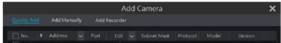
text_image
Add Camera Quickly Add Add Manually Add Recorder No. Address Port Edit Subnet Mask Protocol_Model Somvionconnecting the IP cameras directly. In this situation, if you directly connect one IP camera to PoE5, PoE6, PoE7 or PoE8, the IP camera will be displayed in the camera list automatically; if you connect it to PoE1, PoE2, PoE3 or PoE4, it won't be displayed in the camera list by showing resource conflict; if you just need to connect it to PoE1, PoE2, PoE3 or PoE4, you should first delete the IP camera which occupies the PoE port resource and then reconnect it to the PoE port.
- Take the 8 CH NVR with 8 PoE ports as another example. The resource distribution of the 8 CH IP cameras is shown in the picture below and the adding rules of the IP cameras are similar to the rules mentioned in the above. Please refer to the above for details.
| CH1 | CH2 | CH3 | CH4 | CH5 | CH6 | CH7 | CH8 |
| POB-1 | POB-2 | POB-3 | POB-4 | POB-5 | POB-6 | POB-7 | POB-8 |
b. Please make sure that the internal ethernet port and the IP camera which directly connects to the PoE port through ONVIF protocol are in the same network segment.
The internal ethernet port and the IP camera which directly connects to the PoE port through ONVIF protocol should be in the same network segment, or you will fail to add the IP camera. Log In the IP camera's web client and then enable DHCP (obtain an IP address automatically); or manually change the IP address of the IP camera to make it in the same network segment with the internal ethernet port.
c. Check whether the number of the added IP camera is the maximum.
If the number of the added IP camera is the maximum, the system will show you the message that the IP camera number is beyond the maximum when you directly connect another IP camera to the available PoE port and thus you will fail to add the IP camera.
Q7. The IP camera which directly connects to the PoE port of the NVR through ONVIF protocol is shown in the camera list, but there is no image output, why?
Please make sure the username and password of the IP camera are correct. The IP camera's username and password can be modified through the two ways mentioned as below.
① Click "Edit Camera" in the Camera module of the setup panel to go to the interface as shown below. Click → to modify the username and password of the IP camera (enter the correct username and password of the IP camera in the popup window and then click "OK" button).
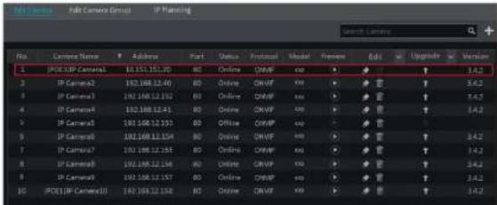
text_image
No. Camera Name Address Part Status Protocol Model Preview Edit Upgrade Version 1 IP Camera10 10.151.15.20 80 Online CHWP exp ▼ ▼ ↑ 3.4.2 2 IP Camera2 102.168.12.40 80 Online CHWP exp ▼ ▼ ↑ 3.4.2 3 IP Camera3 102.168.12.50 80 Online CHWP exp ▼ ▼ ↑ 3.4.2 4 IP Camera4 102.168.12.61 80 Online CHWP exp ▼ ▼ ↑ 3.4.2 5 IP Camera5 102.168.12.57 80 Online CHWP exp ▼ ▼ ↑ 3.4.2 6 IP Camera6 102.168.12.54 80 Online CHWP exp ▼ ▼ ↑ 3.4.2 7 IP Camera7 102.168.12.59 80 Online CHWP exp ▼ ▼ ↑ 3.4.2 8 IP Camera8 102.168.12.54 80 Online CHWP exp ▼ ▼ ↑ 3.4.2 9 IP Camera9 102.168.12.57 80 Online CHWP exp ▼ ▼ ↑ 3.4.2 10 IP Camera10 102.168.12.58 80 Online CHWP exp ▼ ▼ ↑ 3.4.2cannot access the NVR remotely.
Q10. ActiveX control cannot be downloaded. How can I do?
a. IE browser blocks ActiveX control. Please do setup as per the steps mentioned below.
① Open IE browser. Click →Internet Options.

text_image
Print File Zoom (100%) Safety Add site to Start menu View downloads Ctrl+J Manage add-ons F12 Developer Tools Go to pinned sites Compatibility View settings Report website problems Internet options About Internet Explorer② Select Security→Custom Level. Refer to Fig 10-1.
③ Enable all the sub options under "ActiveX controls and plug-ins". Refer to Fig 10-2.
④ Then click "OK" to finish setup.
b. Other plug-ins or anti-virus may block ActiveX. Please disable or do the required settings.
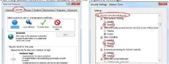
text_image
Internet Options General Active Controls Controls Technologies Advanced Select a zone to view or change security settings. Local network: Trusted info. Rejected video Internet This zone is for Internet settings, except from label in trusted and unloaded items. Security level for the zone about levels for the zone, local level and medium-high Accesses for the various changes before developing potentially unsafe Unloaded Active controls will not be downloaded Security Settings: Internet Zone Active controls and images Active controls (including image) Active controls (including image) Active controls (including image) Active controls (including image) Active controls (including image) Active controls (including image) Active controls (including image)format.
b. Record backed up through web. The record can only be backed up with AVI format through web. The record can be backed up to PC and played by the video player which supports this format.
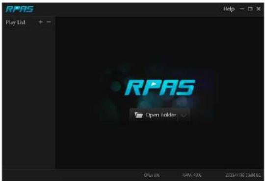
text_image
RPAS Play List RPAS Open Folder Open Link 84% 40% 2019/7/02 15:00:02Fig 11-1
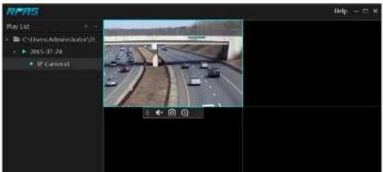
text_image
RPM5 Play 102 C:\Users\Administrator\Dr ▶ 2015.07.24 IP Camera1 Help -Appendix B Calculate Recording Capacity
The recording capacity is mainly up to the record resolution, record stream and bitrate. Different image quality parameters decide different disk capacity occupation in equal times. The bigger the record resolution, record stream and record bitrate is, the more disk capacity is taken up in equal times. The calculation format of recording capacity is shown as below.
Recording Capacity(MB) = Bitrate(Kbps) ÷ 1024 ÷ 8 × 3600 × Recording hours per day × Record Storage Days × channel numbers 3600 means record for an hour (1TB=1024GB, 1GB=1024MB, 1MB=1024KB, 1Byte=8bit).
| Record Bitrate (Kbps) | Used Space (MB/H) | Used Space (MB/D) |
| 10240 | 4500 | 108000 |
| 8192 | 3600 | 86400 |
| 6144 | 2700 | 64800 |
| 4096 | 1800 | 43200 |
| 3072 | 1350 | 32400 |
| 2048 | 900 | 21600 |
| 1024 | 450 | 10800 |
| 768 | 337.5 | 8100 |
| 512 | 225 | 5400 |
| 384 | 168.75 | 4050 |
| 255 | 112.5 | 2700 |
The table below shows the recording capacity requirements for record storage in 30 days.
| Record Bitrate (Kbps) | Recording Capacity(TB) | |||||
| 1CH | 4CH | 8CH | 16CH | 32CH | 64CH | |
| 10240 | 3.09 | 12.36 | 24.72 | 49.44 | 98.88 | 197.76 |
| 8192 | 2.48 | 9.89 | 19.78 | 39.56 | 79.11 | 158.21 |
| 6144 | 1.86 | 7.42 | 14.84 | 29.67 | 59.33 | 118.66 |
| 4096 | 1.24 | 4.95 | 9.89 | 19.78 | 39.56 | 79.11 |
| 3072 | 0.93 | 3.71 | 7.42 | 14.84 | 29.67 | 59.33 |
| 2048 | 0.62 | 2.48 | 4.95 | 9.89 | 19.78 | 39.56 |
| 1024 | 0.31 | 1.24 | 2.48 | 4.95 | 9.88 | 19.78 |
| 768 | 0.24 | 0.93 | 1.86 | 3.71 | 7.42 | 14.84 |
| 512 | 0.16 | 0.62 | 1.24 | 2.48 | 4.95 | 9.89 |
| 384 | 0.12 | 0.47 | 0.93 | 1.86 | 3.71 | 7.42 |
| 256 | 0.08 | 0.31 | 0.62 | 1.24 | 2.48 | 4.95 |
For instance, there is a 32CH NVR recording 24 hours per day and the record stores for 30 days. The NVR adopts dual stream recording. The main stream is 4096Kbos and the sub stream is 1024Kbos, then the total recording capacity is 49.45TB (39.56TB + 9.89TB).
Appendix C Specifications
| Model | N8NRL | N4NRL | |
| System | Compression | Standard H.265 | |
| OS | Embedded Linux | ||
| Video | IPC Input 8CH 4CH | ||
| Network Access Bandwidth | 50Mbps 40Mbps | ||
| Network Access Format | 8MP/5MP/4MP/3MP/1080P/960P/720P@25/30fps | ||
| Output | HDMI>1: 4K×2K/1920x1080/1280×1024, VGA×1: 1920x1080/1280×1024 | ||
| Audio | Network Input | 8CH IPC audio input | 4CH IPC audio input |
| 2-way Audio | RCA×1 | ||
| Local Output RCA×1 | |||
| Record | Record Stream | Dual stream recording | |
| Resolution | 8MP/5MP/4MP/3MP/1080P/960P/720P | ||
| Mode | Manual, schedule, motion, sensor, intelligence | ||
| Playback | Simultaneous Playback | Max 8 CH Max 4CH | |
| Search Mode | EZ search, museum search, time search, event search, bookmark search, snapshot search | ||
| Smart Search | Highlighted color to display camera records in a certain period of time, different colors refer to different record events | ||
| Function | Play, pause, FF, FB, etc. | ||
| Alarm | Mode | Manual, sensor, motion, exception, intelligence | |
| Input | Support IPC alarm input | ||
| Output | Support IPC alarm output | ||
| Linkage | Record, snapshot, presct, e-mail, pop-up window, etc. | ||
| Network | Interface | RI45 10M/100Mbps×1 | |
| PoE Port RJ45×8 RJ45×4 | |||
| Protocol | TCP/IP, PPPoF, DHCP, DNS, DDNS, UPnP, NTP, SMTP | ||
| Web Client | Multiple online users | ||
| Mobile Device | OS | iOS, Android via Speco Blue, SecureGuard Client | |
| Storage | HDD | SATA×1, max 14TB per HDD | |
| Export | Local | By U disk, USB mobile HDD | |
| Network | Yes | ||
| USB | USB | US32.0×2 (one in the front panel and the other in the rear panel) | |