ZIPK8T2 - Security Camera Speco Technologies - Free user manual and instructions
Find the device manual for free ZIPK8T2 Speco Technologies in PDF.

User questions about ZIPK8T2 Speco Technologies
0 question about this device. Answer the ones you know or ask your own.
Ask a new question about this device
Download the instructions for your Security Camera in PDF format for free! Find your manual ZIPK8T2 - Speco Technologies and take your electronic device back in hand. On this page are published all the documents necessary for the use of your device. ZIPK8T2 by Speco Technologies.
USER MANUAL ZIPK8T2 Speco Technologies
Speco Gray Series Kits
speco technologies®
IMPORTANT SAFEGUARDS AND WARNINGS....7
CHAPTER 1 PRODUCT OVERVIEW .... 1
1.1 REAR PANEL 1
1.2 REMOTE CONTROL (FOR REFERENCE ONLY)....1
CHAPTER 2 NVR INSTALLATION & CONNECTION....3
2.1 CONNECTION DIAGRAM 3
2.2 POWER SUPPLY CONNECTION 3
CHAPTER 3 NVR COMMON OPERATIONS....4
3.1 USING THE SUPPLIED MOUSE 4
3.2 USING THE VIRTUAL KEYBOARD .... 5
3.3 PASSWORD ....5
CHAPTER 4 START UP ....7
4.1 START WIZARD 9
4.1.1 Start Wizard....7
4.1.2 Network Configuration....7
4.1.3 Date/Time 9
USER MANUAL
4.2.3 Start Menu....18
4.2.3.1 Unlock and Lock Screen....18
4.2.3.2 Shutdown 18
CHAPTER 5 SYSTEM SETUP....20
5.1 CHANNEL....21
5.1.1 IP Channels 21
5.1.2 Custom RTSP 23
5.1.3 Live....24
5.1.4 Image Control 26
5.1.5 Motion 28
5.1.6 Alam....29
5.1.7 Privacy Mask....30
5.2 RECORD 31
5.2.1 Stream 31
5.2.2 Record 32
USER MANUAL
5.3.2 Exception....36
5.4 NETWORK....37
5.4.1 General 37
5.4.1.1 General 37
5.4.1.2 PPPoE....38
5.4.1.3 Port Configuration 39
5.4.2 DDNS 40
5.4.3 Email 40
5.4.3.1 Email Configuration 41
5.4.3.2 Email Schedule 42
5.4.4 FTP 43
5.5 DEVICE....44
5.5.1 Disk 44
5.5.1.1 Disk 44
5512 SMART 45
USER MANUAL
5.6.3 Multi-user....52
5.6.3.1 Changing Password....53
5.6.3.2 Add New Users 54
5.6.3.3 Setting User Permissions 55
5.6.4 Maintenance 56
5.6.4.1 Log 56
5.6.4.2 Load Default 58
5.6.4.3 Upgrade 59
5.6.4.4 Parameter Management....59
5.6.4.5 Auto Reboot 60
5.6.5 Camera Maintenance 61
5.6.5.1 Upgrade IP Camera....61
5.6.5.2 Load Default Settings for IP Camera 62
5.6.6 System Information....62
5.6.6.1 Information 62
USER MANUAL
6.1.2 Event Search, Playback & Backup....71
6.1.2.1 Event Playback Control 73
6.1.3 Sub-periods Playback....73
6.1.4 Picture Search & View....75
6.1.4.1 Picture Preview Control 77
CHAPTER 7 REMOTE ACCESS VIA WEB CLIENT .... 78
7.1 BASIC SYSTEM ENVIRONMENT REQUIREMENTS 78
7.2 WEB PLUG-IN DOWNLOAD AND INSTALLATION....79
7.3 WEB CLIENT MANAGER 82
7.3.1 Live Interface 82
7.3.2 Playback....85
7.3.2.1 Playback Control Buttons....86
7.3.3 Remote Setting....88
7.3.4 Local Setting 89
CHAPTER 8 VIEWING EXPORTED VIDEO ON PC/MAC 90
USER MANUAL
Welcome
Thank you for purchasing this surveillance system.
Please read this manual carefully before installing and operating the cameras and the NVR (network video recorder).
If technical assistance is needed, please contact Speco Technologies Technical Support.
Phone: 1-800-645-5516 option 3
Email: techsupport@specotech.com
Important Safeguards and Warnings
Please carefully read the following instructions to avoid personal injuries and prevent the equipment and other devices from being damaged.
- Power source (note: please use the power supply that was included)
Never operate the equipment by using an unspecified power supply.
- Never push objects of any kind through the openings on the recorder
Never push objects of any kind through the openings on the NVR to avoid electric shock or other accidents.
- Avoid dusty areas
Do not put the equipment in a dusty area.
- Do not place the equipment in a rainy or humid environment
Do not place the recorder in a humid environment like a basement. If the equipment comes accidentally in contact with water, please unplug the power cable and immediately contact support.
- Keep the surface of the equipment clean and dry
USER MANUAL
Handle the unit gently as rough physical handling may cause malfunction.
8. Use standard lithium battery
After disconnecting power, if the system clock does not continue to work, please replace the standard 3V lithium battery on the main board.
Warning: Turn off the unit before replacing the batteries. Please properly dispose of the used batteries.
9. Put the equipment in a place with good ventilation
The recorder can produce a large amount of heat during operation. Install or put the equipment in a place with good ventilation.
10. The included power adapter can only be used for the single recorder. Do not connect more equipment to the power adapter.
11. Prevent water from splashing on the equipment. Do not place objects containing water on the equipment.
12. Electrical safety
All installation and operation here should conform to local electrical safety codes. The product must be grounded to reduce the risk of electric shock. Speco Technologies assumes no liability or responsibility for all the fires or electric shock caused by improper handling or installation.

Chapter 1 Product Overview
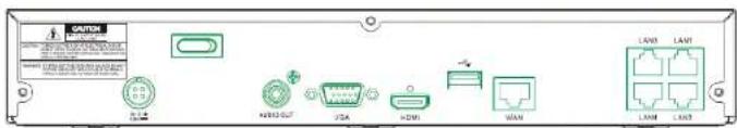
1.1 Rear Panel
text_image
CANR LAN1 LAN2 LAN3 LAN4 LAN5 LAN6 LAN7 LAN8 LAN9 LAN10 LAN11 LAN12 LAN13 LAN14 LAN15 LAN16 LAN17 LAN18 LAN19 LAN20 LAN21 LAN22 LAN23 LAN24 LAN25 LAN26 LAN27 LAN28 LAN29 LAN30 LAN31 LAN32 LAN33 LAN34 LAN35 LAN36 LAN37 LAN38 LAN39 LAN40 LAN41 LAN42 LAN43 LAN44 LAN45 LAN46 LAN47 LAN48 LAN49 LAN50(4-channel recorder shown for reference)
| Item | Physical Port Connection Method | |
| 1 | Power Switch | Startup and shutdown |
| 2 | Power Port | Connect the included power supply |
| 3 | USB Port | Connect USB devices, such as USB mouse and USB flash drive. |
| 4 | HDMI Port | Connect to a monitor or TV |
| 5 | VGA Port | Connect to a monitor with VGA port |
| 6 | Audio Out | Audio signal output, RCA port |
| 7 | WAN Port | Network Interface to router |
| 8 | LAN Ports | Network interface to IP cameras. Also provides power to IP cameras. |
1.2 Remote Control (For Reference Only)
USER MANUAL
| 6 Submenu Go to submenu | ||
| 7 | ▲ | Up arrow key |
| 8 SEL | Press to enter the selected menu item and edit the setting | |
| 9 | ◆ | Left/Right key |
| 10 | ▼ | Down arrow key |
| 11 | ◀◀ | Press to rewind during video playback |
| 12 | ▶▶ | Press to fast forward during video playback |
| 13 | ▶ | Press to play recorded video or enter the playback search menu |
| 14 | ● | Press to start manual recording |
| 15 | ■ | Press to stop manual recording or stop the video playback |
| 16 | ■ | Press to pause the video playback or enter frame-playback mode |
Table 2-1
Chapter 2 NVR Installation & Connection
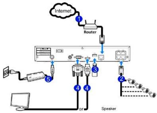
2.1 Connection Diagram
flowchart
graph TD
    A["Internet"] -->|1| B["Router"]
    B --> C["Server"]
    C -->|2| D["Speaker"]
    C -->|3| E["Port 3"]
    C -->|4| F["Port 4"]
    C -->|5| G["Port 5"]
    D --> H["Computer"]
    E --> I["Port 3"]
    F --> J["Port 4"]
    G --> K["Port 5"]
(4-channel recorder connection shown for reference)
2.2 Power Supply Connection
Caution: Use only the supplied power adapter that was included in the package
Connect one and of the power adapter to the power connector on the back of the NVD. Plug the other and
Chapter 3 NVR Common Operations
3.1 Using the Supplied Mouse
1. Left Button:
- Click to select menu options.
During live viewing in split-screen view, double-click on a channel to view it in full-screen. Double-click the channel again to return to split-screen viewing. - Click up on a channel in Live View to open the Camera Quick Toolbar.
- General click and drag actions
2. Right Button:
3.2 Using the Virtual Keyboard
The virtual keyboard will pop up on the screen when data needs to be entered.
Click to toggle the keyboard to
upper case and more punctuation

text_image
2 3 4 5 6 7 8 9 0 w e r t y u i o p [ ] \ a s d f g h j k l ↑ z x c v b n m ← ↑ ← - = ← Move the cursor to right Click to delete a character Click to enterMove the cursor to left
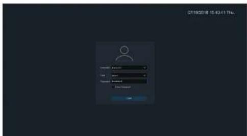
3.3 Password
When the recorder is powered on for the first time, a password is required to set. Please make sure to remember the username and password and save them in a secure place.
USER MANUAL
New Admin Name: set the user name.
New Admin Password: set the admin password. The password must be a combination of 8 characters.
Confirm Password: Enter the password again.
Click Apply to confirm the setup and go to the login interface. Enter the user name & password to log in.
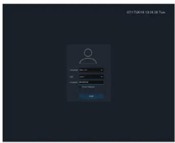
NOTE: If the password is forgotten or lost, please contact support to react the password.
Chapter 4 Start up
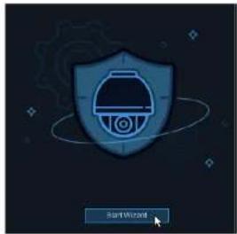
4.1 Start Wizard
The Startup Wizard will help configure the system and get the system up and running quickly.
4.1.1 Start Wizard
Click the Start Wizard button to proceed to the next step
text_image
Start Wizard4.1.2 Network Configuration

USER MANUAL
Check the DHCP box if the recorder is connected to a network with DHCP capability. A router typically has DHCP. The router will assign the network parameters automatically when DHCP is enabled on the recorder. To manually assign parameter values, see below:
IP Address: The IP address identifies the recorder in the network. It consists of four groups of numbers between 0 to 255, separated by periods. For example, "192.168.001.100".
Subnet Mask: Subnet mask is a network parameter which defines a range of IP addresses that can be used in a network. If IP address is like a street where you live then subnet mask is like a neighborhood. The subnet address also consists of four groups of numbers, separated by periods. For example, "255.255.000.000".
Gateway: This address allows the unit to access the Internet. The format of the Gateway address is the same as the IP Address. For example, "192.168.001.001".
DNS1/DNS2: DNS1 is the primary DNS server and DNS2 is a backup DNS server. It is usually enough just to enter the DNS1 server address.
Port
Web Port: This is the port that will be used to log in remotely to the NVR (e.g. using the Web Client). If the default port 80 is already being used by other applications, it must be changed.
4.1.3 Date/Time
Date and Time
Click on the calendar icon to set the current system date.
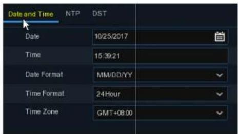
text_image
Date and Time NTP DST Date 10/25/2017 Time 15:39:21 Date Format MM/DD/YY Time Format 24Hour Time Zone GMT+08:00Date: Click on the calendar icon to set the system date.
Time: Click to set the system time.
Date Format: Choose from the drop down menu to set preferred date format.
Time Format: Choose time format between 24Hour and 12Hour.
USER MANUAL

text_image
Date/Time Date and Time NTP DST Enable NTP Server Address pool.ntp.org Update NowCheck the "NTP" box, and select the NTP server.
DST
DST stands for Daylight Saving Time.

text_image
Date and Time NTP DST Enable DST ✓ Time Offset 1Hour ✓ DST Mode Week ✓ Start Time Mar. The 2nd Sun. 02:00:00 End Time Nov. The 1st Sun. 02:00:004.1.4 IP Camera
IP cameras can be added to the NVR through this menu if the included cameras are not connected directly to the PoE ports on the back of the NVR.
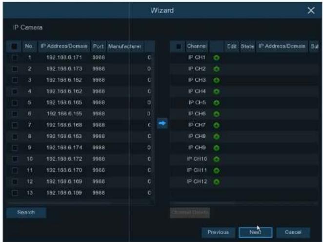
text_image
Wizard IP Camera No IP Address/Domain Port Manufacturer 1 192.193.6.171 9988 C 2 192.193.6.173 9988 O 3 192.193.6.152 9988 C 4 192.193.6.162 9988 C 5 192.193.6.165 9988 O 6 192.193.6.155 9988 O 7 192.193.6.168 9988 C 8 192.193.6.153 9988 C 9 192.193.6.174 9988 O 10 192.193.6.172 9988 C 11 192.193.6.170 9988 C 12 192.193.6.169 9988 C 13 192.193.6.159 9988 C Search Channel Details Previous Next Cancel IP CH1 IP CH2 IP CH3 IP CH4 IP CH5 IP CH6 IP CH7 IP CH8 IP CH9 IP CH10 IP CH11 IP CH12USER MANUAL
Enter the camera's user name & password to add the camera(s). The default credentials are admin/admin.
Click the +button to add an individual IP camera to a single channel.
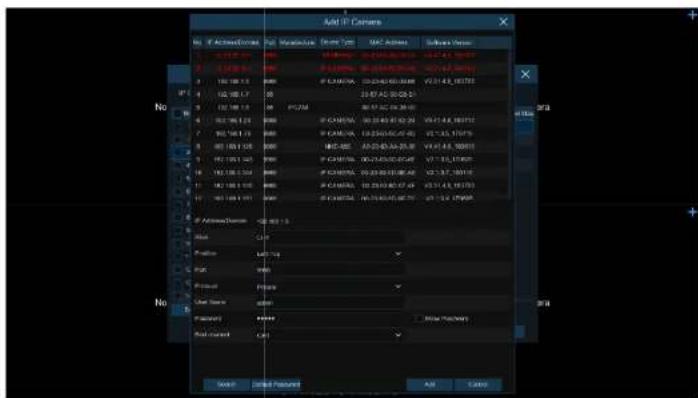
text_image
Add IP Camera No | Active/Current | Max/Max Value | Max Time | MAC Address | Software Address | 1 0.128 Hz 100% 14.64ms 00:35:00:00:00 14:47:43:19:37 2 1.238 Hz 100% 14.64ms 00:35:00:00:00 14:47:43:19:37 3 150 MHz 100% 14.64ms 00:35:00:00:00 14:47:43:19:37 4 162 MHz 100% 14.64ms 00:35:00:00:00 14:47:43:19:37 5 182 MHz 100% 14.64ms 00:35:00:00:00 14:47:43:19:37 6 202 MHz 100% 14.64ms 00:35:00:00:00 14:47:43:19:37 7 222 MHz 100% 14.64ms 00:35:00:00:00 14:47:43:19:37 8 242 MHz 100% 14.64ms 00:35:00:00:00 14:47:43:19:37 9 262 MHz 100% 14.64ms 00:35:00:00:00 14:47:43:19:37 10 282 MHz 100% 14.64ms 00:35:00:00:00 14:47:43:19:37 11 302 MHz 100% 14.64ms 00:35:00:00:00 14:47:43:19:37 12 322 MHz 100% 14.64ms 00:35:00:00:00 14:47:43:19:37 13 342 MHz 100% 14.64ms 00:35:00:00:00 14:47:43:19:37 14 362 MHz 100% 14.64ms 00:35:00:00:00 14:47:43:19:37 15 382 MHz 100% 14.64ms 00:35:00:00:00 14:47:43:19:37 16 402 MHz 100% 14.64ms 00:35:00:00:00 14:47:43:19:37 17 422 MHz 100% 14.64ms 00:35:00:00:00 14:47:43:19:37 18 442 MHz 100% 14.64ms 00:35:00:00:00 14:47:43:19:37 19 462 MHz 100% 14.64ms 00:35:00:00:00 14:47:43:19:37 20 482 MHz 100% 14.64ms 00:35:00:00:00 14:47:43:19:37 21 502 MHz 100% 14.64ms 00:35:00:00:00 14:47:43:19:37 22 522 MHz 100% 14.64ms 00:35:00:00:00 14:47:43:19:37 23 542 MHz 10Og/Hz/Hz/Hz/Hz/Hz/Hz/Hz/Hz/Hz/Hz/Hz/Hz/Hz/Hz/Hz/Hz/Hz/Hz/Hz/Hz/Hz/Hz/Hz/Hz/Hz/Hz/Hz/Hz/Hz/Hz/Hz/Hz/Hz/Hz/Hz/Hz/Hz/Hz/Hz/Hz/Hz/Hz/Hz/Hz/Hz/Hz/Hz/Hz/Hz/Hz/No Active/Demont - <5 Hz > = = = = = = = = = = = = = = = = = = = = = = = = = = = = = = = = = = = = = = = = = = = = = = = = = = = = = = = = = = = = = = = = = = = = = = = = = = = = = = = = = = = = = = = = = = = = = = = = = = = == No Load C# Profile M/F/M# PCB W# Preset Preset Base Temp dW# Preset ***** Load Current C# Add Cancel Add Add CancelClick Search button to search IP cameras, and then click one of the IP camera in the device list.
IP Address/Domain: IP address or domain name of the IP camera
4.1.5 Disk
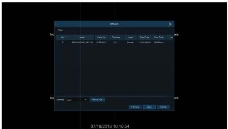
text_image
Disk No Model Send to: Forward Scale FreeTo Free Time In 07/19/2018 10:16:54 No Records Auto Panel HSC Finish Next CancelThe NVR comes with a preinstalled HDD. If for any reason, the HDD needs to be formatted, select the HDD and then click the Format HDD button.
Overwrite: Use this option to overwrite the old recordings on the HDD when the HDD gets full. For example, if the option 7 days is chosen then only the last 7 days of recorded data are kept on the HDD. To prevent overwriting any old recordings, select Disable. If this function is disabled, please check the
4.1.7 Mobile
Scan the QR code with the mobile app to view the NVR remotely through a smartphone.

text_image
Mobile P2P ID P2P ID RSV1907010420595 Local Connection IP Address 192.168.6.28 Subnet Mask 255.255.255.0 Port Web Port 80 Client Port 90004.1.8 Summary
Check "Don't show this window next time" to not display the Start Wizard again when the system is rebooted next time. Click Finish button to save & exit.

USER MANUAL
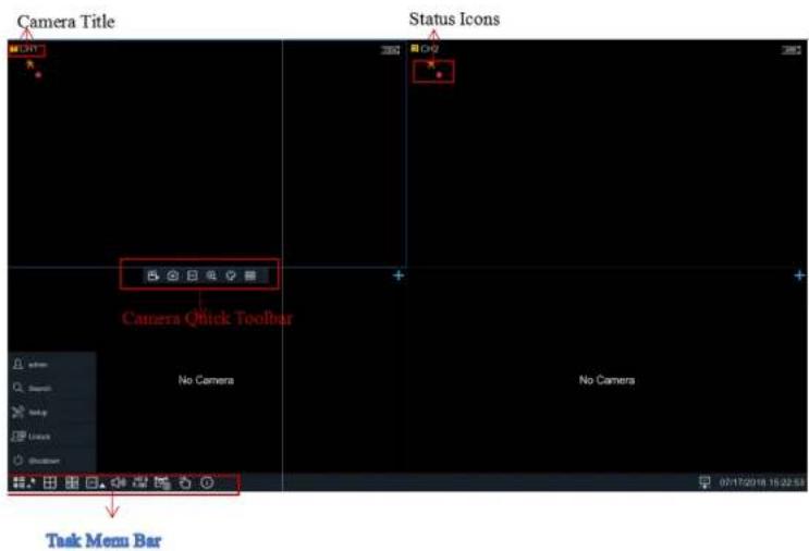
4.2 Live View Screen Overview
text_image
Camera Title Status Icons Camera Quick Toolbar No Camera No Camera Task Menu Bar
This icon indicates the HDD is read-only.
No Camera: IP camera is not connected.

Click to open Quick Add menu to add IP camera

Click to edit current IP camera
4.2.1 Camera Quick Toolbar
In live view, click the left button of the mouse on a channel to display the Camera Quick Toolbar.


Click to manually record the channel immediately. If the manually recording is in process, the icon will be in red color. Click one more time to stop manual record.

Click to save a snapshot of the current camera image.

Click to play the last 5 minutes of recording of this channel

Click to zoom into the channel.
4.2.2 Task bar


Click to open the Start Menu

Click to choose different layout for live view

Click to start viewing channels in a sequence

Quick playback. If chosen, the recording for all channels from the beginning of the day will
start playing back. If the arrow is clicked, playback from the last 5s, 10s, 30s, 1min, and 5min can be chosen.

Click to adjust the audio volume

Click to switch all IP channels between main stream and sub stream for live view

Click to switch among real-time, balanced, or smooth view. The view effect modes affect
only the live view video quality by bitrate and frame rate but do not affect the recording quality.
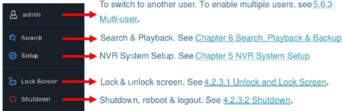
4.2.3 Start Menu
text_image
admin Search Setup Lock Screen Shutdown To switch to another user. To enable multiple users, see 5.6.3 Multi-user. Search & Playback. See Chapter 6 Search, Playback & Backup NVR System Setup. See Chapter 5 NVR System Setup Lock & unlock screen. See 4.2.3.1 Unlock and Lock Screen. Shutdown, reboot & logout. See 4.2.3.2 Shutdown.4.2.3.1 Unlock and Lock Screen
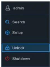
text_image
admin Search Setup Unlock ShutdownThe screen will be locked to protect unauthorized OSD operation if there is no user interaction after 1 minute.
If necessary, the screen can be locked manually. To do so, go to the Start Menu, and then click the Lock Screen icon 📷 to lock the system immediately.
If the system is locked, click the Unlock icon 🔒 to unlock the system for further operation.
USER MANUAL
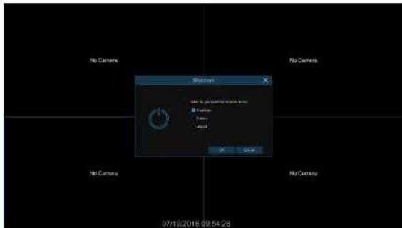
text_image
No Camera No Camera Shubilon Add to the user's name or name in this ● 100 percent ● 95 percent ● 90 percent OK Cancel 07/10/2018 09:54:28If Logout is chosen, the live view screen will disappear. Log in to the system again for operation.
text_image
07/18/2018 15:43:11 Thu.Chapter 5 System Setup
Go to Start Menu→Setup.
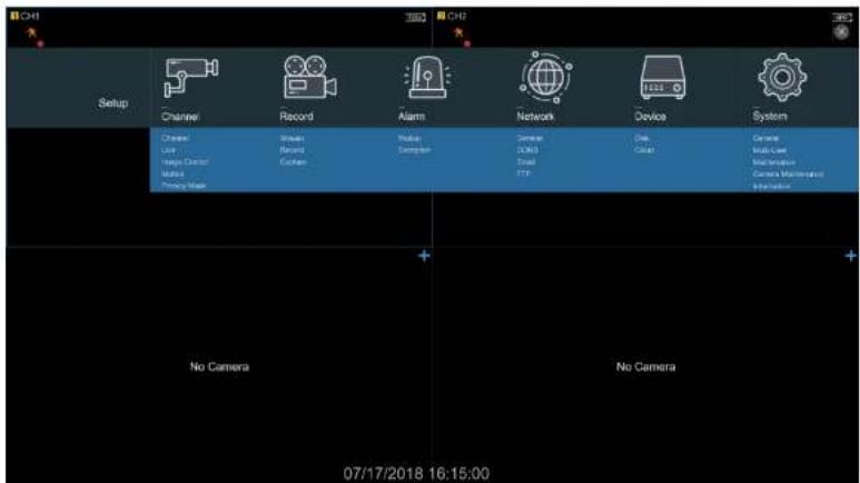
text_image
CHI Setup Channel Record Alarm Network Device System Channel Stream Round Midspan General LANOS Dial Color Camera Multi-Layer Maintenance Camera Maintenance No Camera No Camera 07/17/2018 16:15:005.1 Channel
Available options in this section are: camera configuration, live view display, manage IP cameras, adjust IP camera's image, motion setup, and privacy mask setup.
5.1.1 IP Channels
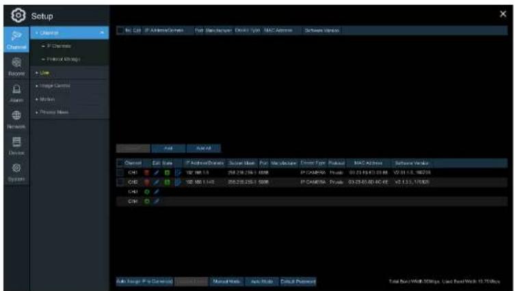
text_image
Setup File Edit IP ActiveCode Port Scan/Server: Open Type MAC Address Software Window Channel IP Chemistry Protocol Linking Live Image Currency Microsoft Primary Name Auto Auto Web Channel Edit Rate IP ActiveCode Show User Put Modulator Event Type Pickup MAC Address Software Window CHS 102.000 1.142 256-238-225-1 500K IP CHAMEN - Private 03.25.00.00 AC KE V2.1.1.1.17805 CHS 102.000 1.142 256-238-225-1 500K IP CHAMEN - Private 03.25.00.00 AC KE V2.1.1.1.17805 CHS Auto Target IP to Generate Manual Manual Web Help Tools Tools Preview Total Run/Work 30Mips, Used Run/Work 12.75MipsClick Search to search for IP cameras on the local network. Click Add to add an individual IP camera
USER MANUAL

text_image
IP Address/Domain 192.168.1.151 Alias CH17 Position Left-Top Port 9988 Protocol Private User Name admin Password Show Password Bind channel CH17 Search Add CancelClick Search button to search for IP cameras, and then click one of the IP cameras in the device list.
IP Address/Domain: IP address or domain name of the IP camera
Alias: Nickname of the channel
Position: Position to display the camera name on the screen.
Dart: Part of the ID camera/leave it at default unless it was specifically changed previously on the
USER MANUAL
Auto Assign IP to Camera(s): If for any reason, the IP camera's IP address was set to a different network segment as the NVR's internal camera network segment, this option can be used to change the camera back to the network segment that the NVR recognizes.
Channel Delete: Choose one or more IP cameras, and click this button to delete them from the channels.
5.1.2 Custom RTSP
Custom RTSP URLs can be used to get video streams from 3^rd party IP cameras where their respective RTSP URLs are known.

text_image
Setup C++ Project C++ Project C++ Project C++ Project C++ Project C++ Project C++ Project C++ Project C++ Project C++ Project C++ Project C++ Project C++ Project C++ Project C++ Project C++ Project C++ Project C++ Project C++ Project C++ Project C++ Project C++ Project C++ Project C++ Project C++ Project C++ Projects C++ Projects C++ Projects C++ Projects C++ Projects C++ Projects C++ Projects C++ Projects C++ Projects C++ Projects C++ Projects C++ Projects C++ Projects C++ Projects C++ Projects C++ Projects C++ Projects C++ Projects C++ Projects C++ Projects C++ Projects C++ Projects C++ Projects C++ Projects C++ Projects C++ Properties C++ Properties C++ Properties C++ Properties C++ Properties C++ Properties C++ Properties C++ Properties C++ Properties C++ Properties C++ Properties C++ Properties C++ Properties C++ Properties C++ Properties C++ Properties C++ Properties C++ Properties C++ Properties C++ Properties C++ Properties C++ Properties C++ Properties C++ Properties C++ Properties C++ Property100% (not applicable) C++ Property100% (not applicable)USER MANUAL
5.1.3 Live
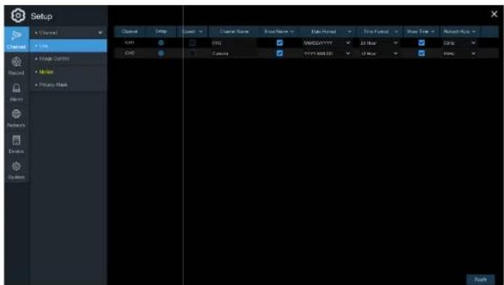
text_image
Setup Channel Flow Wave Control Mode Private Mask CHD CHD Chord Name Base Name Data Path Free Path Base Path Nivel-Run CHD CHD AMODYYYY 24 Hour CHD YYYY 888.00 12 Hour F000 AutoChannel Name: Nickname of the IP camera.
Setup: Click the icon to go to the setup page.
USER MANUAL
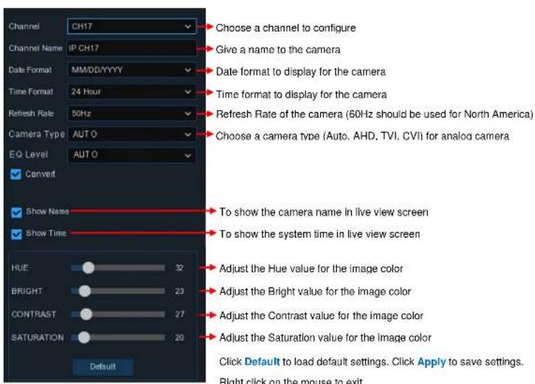
text_image
Channel CH17 Choose a channel to configure Channel Name IP CH17 Give a name to the camera Date Format MM/DD/YYYY Date format to display for the camera Time Format 24 Hour Time format to display for the camera Refresh Rate 50Hz Refresh Rate of the camera (60Hz should be used for North America) Camera Type AUTO Choose a camera type (Auto, AHD, TVI, CVI) for analog camera EQ Level AUTO Convert Show Name To show the camera name in live view screen Show Time To show the system time in live view screen HUE 32 Adjust the Hue value for the image color BRIGHT 23 Adjust the Bright value for the image color CONTRAST 27 Adjust the Contrast value for the image color SATURATION 20 Adjust the Saturation value for the image color Default Click Default to load default settings. Click Apply to save settings. Right click on the mouse to exit.USER MANUAL
5.1.4 Image Control
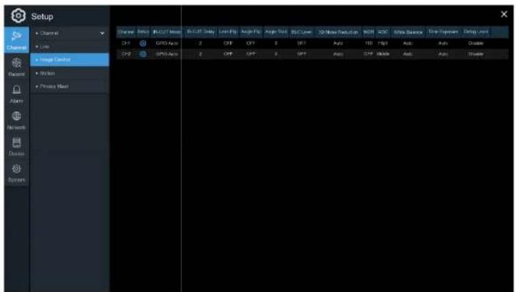
text_image
Setup Channel Link Image Control Motion Please Next Channel GND Auto GND Auto GND Auto Auto Auto Auto Auto Auto Auto Auto Auto Auto Auto Auto Auto Auto Auto Auto Auto Auto Auto Auto Auto Auto Auto Auto Auto Auto Auto Auto Auto Auto Auto Auto Auto Auto Auto Auto Auto Auto Auto Auto Auto Auto Auto Auto Auto Auto Auto Auto Auto Auto Auto 0x10000000000000000000000000000000000000000000000000000000000000000000000000000000000000000000000000000 Channel GND Auto GND Auto GND Auto GND AutoSetup: Click the icon to go to the setup page.
USER MANUAL
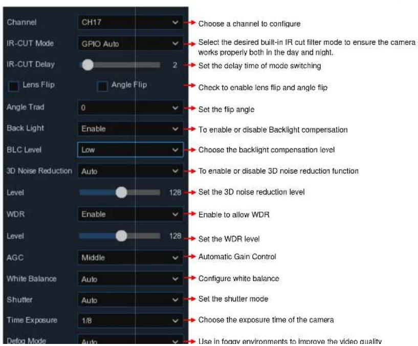
text_image
Channel CH17 IR-CUT Mode GPIO Auto IR-CUT Delay 2 Lens Flip Angle Flip Choose a channel to configure Select the desired built-in IR cut filter mode to ensure the camera works properly both in the day and night. Set the delay time of mode switching Check to enable lens flip and angle flip Angle Trad 0 Set the flip angle Back Light Enable To enable or disable Backlight compensation BLC Level Low Choose the backlight compensation level 3D Noise Reduction Auto To enable or disable 3D noise reduction function Level 128 Set the 3D noise reduction level WDR Enable Enable to allow WDR Level 128 Set the WDR level AGC Middle Automatic Gain Control White Balance Auto Configure white balance Shutter Auto Set the shutter mode Time Exposure 1/8 Choose the exposure time of the camera Defog Mode Auto Use in foggy environments to improve the video qualityUSER MANUAL
5.1.5 Motion
Configure motion detection options in this section.
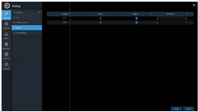
text_image
Setup Channel 1.000 Image Control My Web Privacy Maps Channel Audio Audio Smoothy CH1 CH2 OK Cancel ApplySetup: Click the icon to go to the setup page.

text_image
Motion Detection Area:Sensitivity: Set the sensitivity level. Level 1 the lowest sensitivity level while level 8 is the highest sensitivity level.
5.1.6 Alarm
Click the Alarm button to configure the motion detection alarm actions:

text_image
Setup e Data Thermal Static Post-Recording Show Messages Send Print Post Screen All Us Open Ctrl Double Ctrl 30 p Ctrl Enable Ctrl 80 p Ctrl OK OKBuzzer: The NVR can use its internal buzzer to emit an alarm tone. The buzzer duration can be set
USER MANUAL
Send Email: Select to let the NVR send an email when the motion is detected. Email must be set up first in the Network section in order for this to work.
Full Screen: If this function is enabled and a motion is detected in a channel, that channel will go to full screen.
FTP Upload: To upload alarm images to an FTP server when motion is detected. To set up FTP, see 5.4.4 FTP.
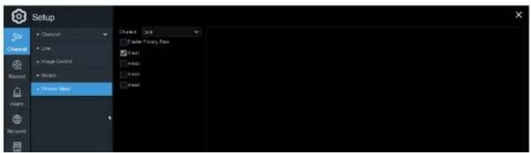
5.1.7 Privacy Mask
Privacy mask can be used to cover certain areas of the image where viewing/recording is not desired. Up to 4 privacy zones in any size and location on the camera image can be set up. Enable Privacy Zone, and choose the number of zones that are needed. The zone(s) appear as red outlined boxes. Click the bottom right corner of the box and drag it to any size to create the privacy zone. Click Apply to save.
text_image
Setup Channel Line Image Control Motion Fisher Maps Channel 3x4 Speed Foreg Time Flash Flash2 Flash0 Flash15.2 Record
This section allows for configuration of recording settings.
5.2.1 Stream
The IP cameras have multiple simultaneous streams which are used for different purposes. The main stream defines the recording video quality which will be saved in the HDD. The sub stream defines the video quality for remote access viewing, such as the web client. The mobile stream defines the video quality for remote viewing with the mobile app.

text_image
Setup Stream Stream Type Streamline F/S Video Stream Type Stream Color Video Quality Stream Mask Stream Stream Stream Stream Stream Stream Stream Stream Stream Stream Stream Stream Stream Stream Stream Stream Stream Stream Stream Stream Stream Stream Stream Stream Stream Stream Stream Stream Stream Stream Stream Stream Stream Stream Stream Stream Stream Stream Stream Stream Stream Stream Stream Stream Stream Stream Stream Stream Stream Stream River River River River River River River River River River River River River River River River River River River River River River River River RiverUSER MANUAL
Bitrate Mode: To set a custom bitrate value, choose the User-defined mode. To have the system set a recommended bitrate value based on the selected resolution of the stream, choose the Predefined mode.
Bitrate: Set the bitrate value. Note that higher bitrate values will result in higher image quality, but will also consume more storage space on the HDD.
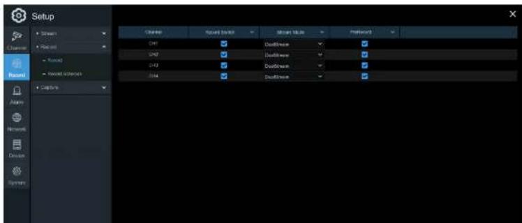
5.2.2 Record
Configuration of the channel recording parameters.
5.2.2.1 Record
text_image
Setup Current Forward Downlink Current Style Position Current Forward Downlink Current Downlink Current Downlink Current Back Name Networks Device Systems5.2.2.2 Record Schedule
Set a recording schedule for normal (continuous) and/or motion recording. To set the recording mode, click on the mode (Normal or Motion) and then drag the cursor to mark the time slots. The recording schedule must be set for each channel. Use the Copy function to set the same schedule as the initial channel that was set, for all other channels. Click Apply to save the settings.
Channel: Select the channel to set its recording schedule.
Normal: Continuous recording (green markers).

text_image
Setup Channel Record Record Sequence Calculate SUM MCM YUE VEB THB FDI SAT Normal Values5.2.3 Capture
This section allows for configuration of image capture (snapshot) settings.
5.2.3.1 Capture

text_image
Setup Stream Recent Capture Capture Window Capture (Short) Alarm Network Device System Customs Auto Capture Smart Type Home space Asset Feature CHF Main Stream 6x 6x 408 Main Stream 5x 5x CHF Main Stream 7x 7x CHF Main Stream 8x 8x Copy Default ApplyAuto Capture: Enable or disable automatic capturing for the channel.
Stream Tyne: Select the image resolution between main stream or sub stream
USER MANUAL
5.2.3.2 Capture Schedule

text_image
Setup Chamber Ctrl 0 2 8 6 9 12 14 16 18 20 22 Normal Normal Normal Normal Normal Normal Normal Normal Normal Normal Normal Normal Normal Normal Normal Normal Normal Normal Normal Normal Normal Normal Normal Normal Normal Normal Normal Normal Normal Normal Normal Normal Normal Normal Normal Normal Normal Normal Normal Normal Normal Normal Normal Normal Normal Normal Normal Normal Normal Normal Conc Concl Concl Concl Concl Concl Concl Concl Concl Concl Concl Concl Concl Concl Concl Concl Concl Concl Concl Concl Concl Concl Concl Concl Concl Concl Concl Concl Concl Concl Concl Concl Concl Concl ConclChannel: Select the channel to set its capture schedule.
Normal: Continuous capture (green markers).
Motion: Motion capture (vellow markers).
5.3 Alarm
This section allows for configuration of alarm parameters.
5.3.1 Motion
Refer to 5.1.6 Alarm
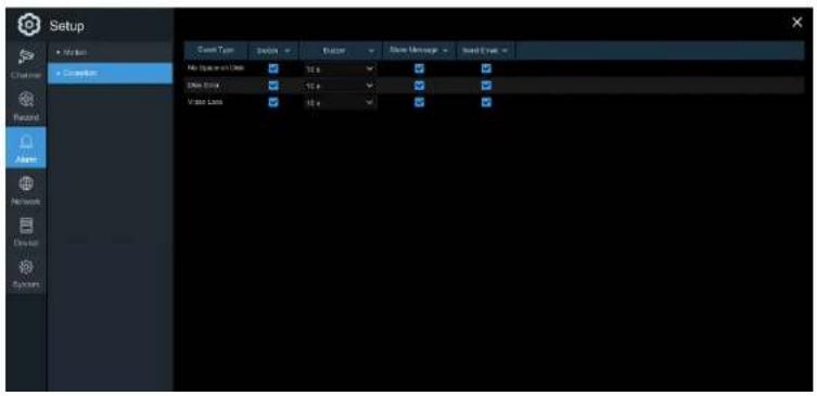
5.3.2 Exception
The NVR can detect different types of errors to notify the operator.
text_image
Setup Auto Conversion Context Type Options Event Close Message Send Event Auto Sequence Data 10 s Video Block 10 s Video Loss 10 sUSER MANUAL
Buzzer: Set the buzzer duration when an event occurs (Off/10s/20s/40s/60s). To disable the buzzer, select OFF.
Show Message: Check the box to display a message on the screen when an event occurs.
Send Email: Lets the NVR send an email when an event occurs.
5.4 Network
Configure network settings of the NVR.
5.4.1 General
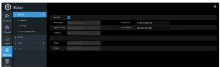
5.4.1.1 General
text_image
Setup General Internal Private Test Configuration DNS C++MOS C++MOS FTP ENCF IP Address: 10000000000 IP Address: 913310.528.163 Subnet Mask: 0000000000 Subnet Mask: 252.000.000.000 Subnet Mask: 252.000.000.000 Networks ENCF1 ENCF2 ENCF1-ENCF2-ENCF2-ENCF2-ENCF2-ENCF2-ENCF2-ENCF2-ENCF2-ENCF2-ENCF2-ENCF2-ENCF2-ENCF2-ENCF2-ENCF2-ENCF2-ENCF2-ENCF2-ENCF2-ENCF2-ENCF2-ENCF2-ENCF2-ENCF2-ENCF2-ENCFUSER MANUAL
IP Address: The IP address identifies the NVR in the network. It consists of four groups of numbers between 0 to 255, separated by periods. For example, "192.168.001.100".
Subnet Mask: Subnet mask is a network parameter which defines a range of IP addresses that can be used in a network. If IP address is like a street where you live then subnet mask is like a neighborhood. The subnet address also consists of four groups of numbers, separated by periods. For example, "255.255.000.000".
Gateway: The gateway allows the NVR to access the Internet. The format of the Gateway address is the same as the IP Address. For example, "192.168.001.001".
DNS1/DNS2: DNS1 is the primary DNS server and DNS2 is a backup DNS server. It is usually sufficient just to enter the DNS1 server address.
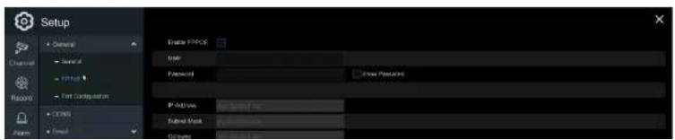
5.4.1.2 PPPoE
text_image
Setup General Serial FTP Test Configuration COSYS Send Enable Protocol State Protocol New Process IP Address: COSYS Inc. Subset Work: Create ProtocolUSER MANUAL
Check the "Enable PPPOE" box and then enter the User name & Password of PPPoE.
Click Apply to save and the system will reboot to activate the PPPoE setting.
5.4.1.3 Port Configuration

text_image
Setup Command Cancel Target Test Computation USB Ctrl FTP Network Desktop Systems With TCP 50000 Clear TCP 50000 TCP2 Port 50004 Settings IP Channel: http://F10-F10/AG Address: Export Data transfer: Update download USB TCP Comms Delete ApplyWeb Port: This is the port that will be used to log in remotely to the NVR (e.g. using the Web Client). If the default port 80 is already taken by other applications, please change it.
5.4.2 DDNS
Configure DDNS settings. Speco Technologies provides a free DDNS service. By using DDNS, the external remote IP address of the device does not have to be known to remotely access the NVR.

text_image
Setup 5.0004 E:\Users\Server\My Documents\123\My Documents\123\My Documents\123\My Documents\123\My Documents\123\My Documents\123\My Documents\123\My Documents\123\My Documents\123\My Documents\123\My Documents\123\My Documents\123\My Documents\123\My Documents\123\My Documents\123\my Documents\123\my Documents\123\my Documents\123\my Documents\123\my Documents\123\my Documents\123\my Documents\123\my Documents\123\my Documents\123\my Documents\123\my Documents\123\my Documents\123\my Documents\123\my Documents\123\my Documents\nServer: 5.0004\nServer: 5.0004\nServer: 5.0004\nServer: 5.0004\nServer: 5.0004\nServer: 5.0004\nServer: 5.0004\nServer: 5.0004\nServer: 5.0004\nServer: 5.0004\nServer: 5.0006\nServer: 5.0006\nServer: 5.0006\nServer: 5.0006\nServer: 5.0006\nServer: 5.0006\nServer: 5.0006\nServer: 5.0006\nServer: 5.0006\nServer: 5.0006\nServer: 5.0007\nServer: 5.0007\nServer: 5.0007\nServer: 5.0007\nServer: 5.0007\nServer: 5.0007\nServer: 5.0007\nServer: 5.0007\nServer: 5.0007\nServer: 5.0012\nServer: 5.0012\nServer: 5.0012\nServer: 5.0012\nServer: 5.0012\nServer: 5.0012\nServer: 5.0012\nServer: 5.0012\nServer: 5.0012\nServer: 5.0012\nServer: 5.0013\nServer: 5.0013\nServer: 5.0013\nServer: 5.0013\nServer: 5.0013\nServer: 5.0013\nServer: 5.0013\nServer: 5.0013\nServer: 5.0014\nServer: 5.0014\nServer: 5.0014\nServer: 5.0014\nServer: 5.0014\nServer: 5.0014\nServer: 5.0014\nServer: 5.0014\nServer: 5.0014\nServer: 5.0014\nServer: 5.0015\nServer: 5.0015\nServer: 5.0015\nServer: 5.0015\nServer: 5.0015\nServer: 5.0015\nServer: 5.0015\nServer: 5.0016\nServer: 5.0016\nServer: 5.0016\nServer: 5.0016\nServer: 5.0016\nServer: 5.0016\nServer: 5.0016\nServer: 5.0017\nServer: 5.0017\nServer: 5.0017\nServer: 5.0017\nServer: 5.0017\nServer: 5.0017\nServer: 5.0018\nServer: 5.0018\nServer: 5.0018\nServer: 5.0018\nServer: 5.0018\nServer: 5.0019\nServer: 5.0019\nServer: 5.0019\nServer: 5.0019\nServer: 5.002DDNS: Check to enable DDNS.
Domain: specoXXXXXX.specoddns.net. The last 6 characters "XXXXXX" are the last 6 characters of the NVR's Mac address.
After all parameters are entered, click Test DDNS to test the DDNS settings. If the test result is
USER MANUAL

text_image
Setup Channel USB Server Email Serial Email Configuration Email Configuration Serial WiFi Provider 1 WiFi Provider 2 WiFi Provider 3 Internet Send to: Send to: Send to: Send to: Send to: Send to: Send to: Send to: Send to: Send to: Send to: Send to: Send to: Send to: Send to: Send to: Send to: Send to: Send to: Send to: Send to: Send to: Send to: Send to: Send to: Send to: Send to: Send to: Send to: Send to: Send to: Send to: Send to: Send to: Send Options Options Options Options Options Options Options Options Options Options Options Options Options Options Options Options Options Options Options Options Options Options Options Options Options Options Options Options Options Options Options Options Options Options Options Options Options Options Options Options Options Options Options Options Options Options Options Options Options Options Miscnion: Normalized (0) Normalized: Normalized (0) Normalized: Normalized (0) Normalized: Normalized (0) Normalized: Normalized (0) Normalized: Normalized (0) Normalized: Normalized (0) Normalized: Normalized (0) Normalized: Normalized (0) Normalized: Normalized (0) Normalized: Normalized (0) Normalized: Normalized (0) Normalized: Normalized (0) Normalized: Normalized(0) Normalized: Normalized(0) Normalized: Normalized(0) Normalized: Normalized(0) Normalized: Normalized(0) Normalized: Normalized(0) Normalized: Normalized(0) Normalized: Normalized(0) Normalized: Normalized(0) Normalized: Normalized(0) Normalized: Normalized(0) Normalized: Normalized(0) Normalized: Normalized(0) Normalizonal: Normalized(0) Normalizonal: Normalized(0) Normalizonal: Normalized(0) Normalizonal: Normalized(0) Normalizonal: Normalized(0) Normalizonal: Normalized(0) Normalizonal: Normalized(0) Normalizonal: Normalized(0) Normalizonal: Normalized(0) Normalizonal: Normalized(0) Normalizonal: Normalized(0) Normalizonal : Normalized(0) Normalizonal : Normalized(0) Normalizonal : Normalized(0) Normalizonal : Normalized(0) Normalizonal : Normalized(0) Normalizonal : Normalized(0) Normalizonal : Normalized(0) Normalizonal : Normalized(0) Normalizonal : Normalized(0) Normalizonal : Normalized(0) Normalizonal : Normalized(0) Normalizonal : Standardization(0) Normalizonal : Standardization(0) Normalizonal : Standardization(0) Normalizonal : Standardization(0) Normalizonal : Standardization(0) Normalizonal : Standardization(0) Normalizonal : Standardization(0) Normalizonal : Standardization(0) Normalizonal : Standardization(0) Normalizonal : Standardization(0) Normalizonal : Standardization(0) Normalizonal : Standardization 168.1.1.1.1.1.1.1.1.1.1.1.1.1.1.1.1.1.1.1.1.1.1.1.1.1.1.1.1.1.1.1.1.1.1.1.1.1.1.1.1.1.1.1.1.1.1.1.1.1.1.5.4.3.1 Email Configuration
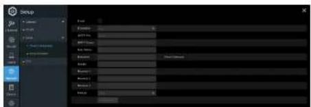
text_image
Setup File Size Name: Color: Balance: Balance1: Balance2: Balance3:USER MANUAL
User Name: Enter the email address of the sender.
Password: Enter the password of the email address.
Password: Display name of the sender.
Receiver 1\~3: Enter the email address(es) that will receive the notifications.
Interval: Configure the length of the time interval between the notification emails from the NVR.
To make sure all settings are correct, click Test Email The system will send an automated email message to the email addresses that were specified.
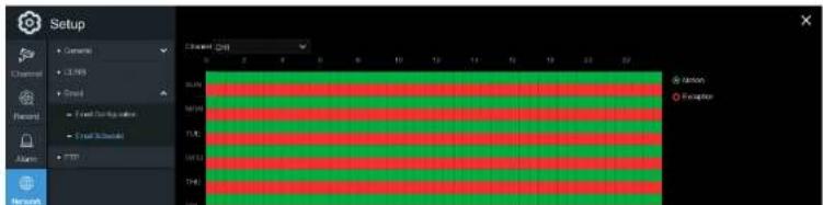
5.4.3.2 Email Schedule
The schedule must be set in order for email notifications to be sent properly..
text_image
Setup Channel Channel Forecast Alarm Network Channel Chiff 0 2 4 6 8 10 12 14 16 18 20 SLR MTR FLE VTR THI Ration ExceptionUSER MANUAL
Red: Exception (HDD full, HDD error, or Video Loss).
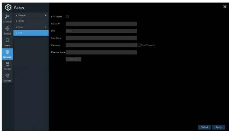
5.4.4 FTP
Snapshots can be uploaded to an existing FTP server configured through this section.
text_image
Setup General CPNS Direct Record FTP FTP Address Server IP Port Last Name Password Directory Name Last Name User Password Default ApplyFTP Enable: Click to enable the FTP function.
5.5 Device
Disk and Cloud configuration.
5.5.1 Disk
5.5.1.1 Disk
Check and configure the internal HDD(s). The HDD already comes formatted with the system. Format the HDD only when necessary for some reason.
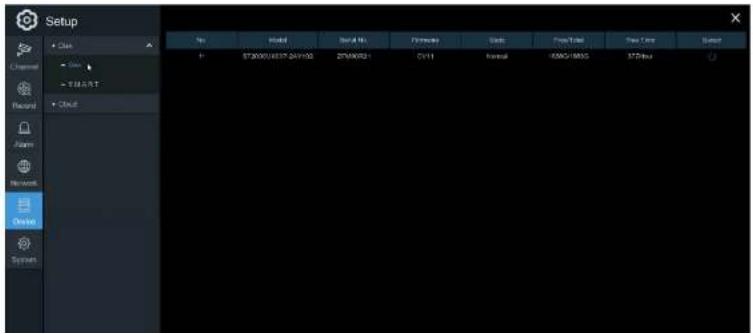
text_image
Setup Class Channel Current Record Alarm Network Desktop System Name Model Serial No. Performance Units Free/Total Free Time Reset ST2000/USB7-04V193 ST2000B1 CVM Control USB1/BMS STBus ST2000/USB7-04V193 ST2000B1 CVM Control USB1/BMS STBus5.5.1.2 S.M.A.R.T
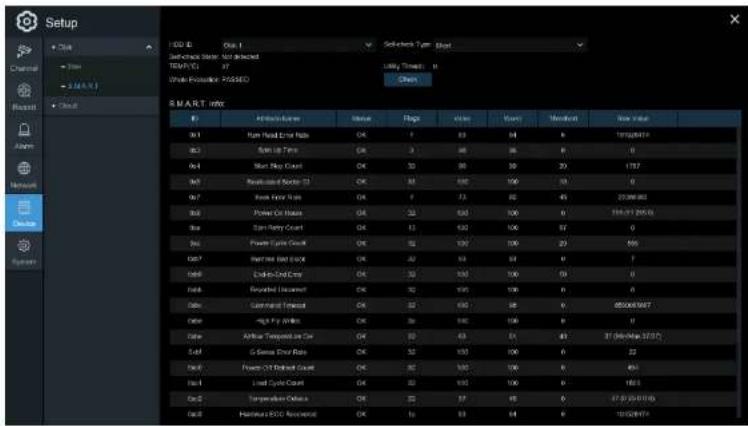
This function can be used to display technical information on the installed hard. Tests can be performed (there are three types available) to evaluate and detect potential drive errors.
text_image
Setup OK OK Set Back Stop: Not Required TEMP/VE 37 Work-Allocation PASSED Chips S M A R T i n t o ID A100000000000000000000000000000000000000000000000000000000000000000000000000000000000000000000 9x1 9x2 9x3 9x4 9x5 9x6 9x7 9x8 9x9 9x10 9x11 9x12 9x13 9x14 9x15 9x16 9x17 9x18 9x19 9x20 9x21 9x22 9x23 9x24 9x25 9x26 9x27 9x28 9x29 9x30 9x31 9x32 9x33 9x34 9x35 9x36 9x37 9x38 9x39 9x40 9x41 9x42 9x43 9x44 9x45 9x46 9x47 9x48 9x49 9x50 9x51 9x52 9x53 9x54 9x55 9x56 9x57 9x58 9x59 9x60 9x61 9x62 9x63 9x64 9x65 9x66 9x67 9x68 9x69 9x70 9x71 9x72 9x73 9x74 9x75 9x76 9x77 9x78 9x79 9x80 9x81 9x82 9x83 9x84 9x85 9x86 9x87 9x88 9x89 9x90 9x91 9x92 9x93 9x94 9x95 9x96 9x97 9x98 9x99 10.1.1.1.1.1.1.1.1.1.1.1.1.1.1.1.1.1.1.1.1.1.1.1.1.1.1.1.1.1.1.1.1.1.1.1.1.1.1.1.1.1.1.1.1.1.1.1.1.1.1.2.2.2.2.2.2.2.2.2.2.2.2.2.2.2.2.2.2.2.2.2.2.2.2.2.2.2.2.2.2.2.2.2.2.2.2.2.2.2.2.2.2.2.2.2.2.2.2.2.2.3.Whole Evaluation not passed, continue to use the disk: If for some reason the hard drive has
detected a fault (such as one or more bad sectors), you can instruct the NVD to continue paying to the
USER MANUAL
Conveyance: This is a very quick test that verifies that the mechanical parts of the hard drive are working.
Note: When performing a test, the NVR will continue to work as normal. If an HDD S.M.A.R.T error is found, the HDD can continue to be used, but there will be a risk to lose recording data. At this point, the HDD may have to be replaced. Contact support when this occurs.
5.5.2 Cloud
Dropbox can be used to upload snapshots for motion alarms. Note that email must be configured and the HDD must have free space in order for Dropbox to work properly.
Cloud Storage: Check to enable the Dropbox function.
Alarm Detection: Check to enable Dropbox uploads for the specified channel.
Driver Name: Custom name for the channel for indication on the uploaded file name.
Activate Cloud: Click to send an authentication email to the receiver email address that was specified in the email configuration section.
Note: When the Activate Cloud button is pressed, an email will be sent to the receiver email address with a link to authenticate the NVR with Dropbox. Make sure that the PC that's accessing the link is on the same local network as the NVR. Click on the link to bring up this screen:
USER MANUAL
Make sure to click on the link within 3 minutes of receiving the email. Enter the local IP address of the NVR in the IP Address field (e.g. http://192.168.0.XXX) and specify the correct HTTP port. Click Authorize.
Enter the user name and password of the NVR. The browser will redirect to Dropbox. Log in to Dropbox as necessary. Go to account settings and then the Connected apps tab. If Dropbox was activated properly, under the Linked apps section, there will show an app called "DVRCloudStorage".
USER MANUAL
5.6 System
General system configuration
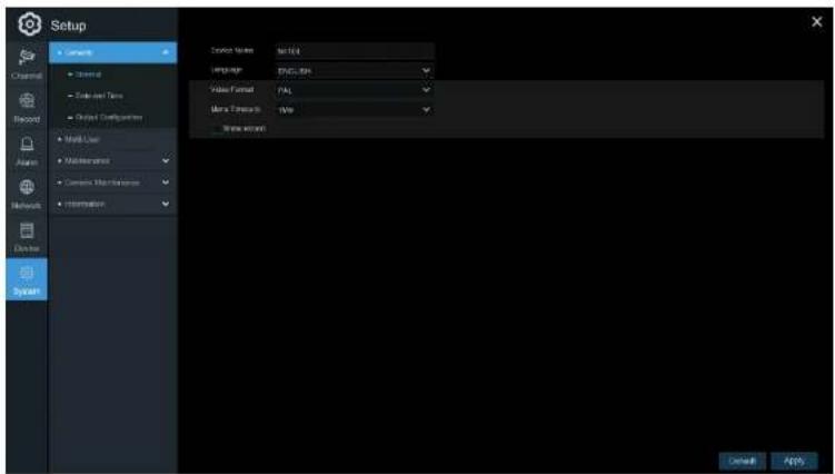
5.6.1 General
text_image
Setup Language Name: Set ID Language: ENGLATION Video Format: PAL Time Wizard: Time Wizard Cancel ApplyDevice Name: Enter the desired name for the NVR. The name can include both letters and numbers.
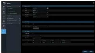
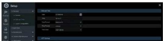
5.6.1.1 Date and Time

text_image
Setup Channel Current Data and Time Output Configuration Multi User Monitoring Current Master/Minimize Information Data and Time Date: 2017/2/2018 Time: 16:36:48 Data Formal: MACD/XY Time Formal: SWBGB Time Date: QNT-00:00 NFT Settings Enable NFT Server Position: pre-mag reg EMT Settings Enable OMT Time Offset: 5ms OCT Shift: 0ms Start Time: Max. Title: 2nd Scan: 02:00:00 End Time: Max. Title: 1st Scan: 02:00:00 Default ApplyDate & Time
Date: Click the calendar icon to change the date.
Time: Click the box to change the time.
Date Format: Select the preferred date format.
5.6.1.2 NTP Settings
The NTP (Network Time Protocol) function allows the NVR to automatically sync its clock with a time server over the Internet. This gives it the ability to constantly have an accurate time setting (the NVR will periodically sync automatically).
text_image
Temp Balance Temp Balance BalanceCheck to enable the NTP, and select a Server Address, click Update Now to manually sync the date & time.
Click Apply to save the settings.
5.6.1.3 DST Settings
DST (Daylight Saving Time) configuration.
text_image
Setup Data and View Name: 2014-03-01 View: 60.0000 Data Point: Measurement Data Points: 0.0000 Data Points: 0.0000 Output: 0.0000USER MANUAL
Enable DST: Select when Daylight Saving starts and ends:
Week: Select the month, a particular day and time when Daylight Saving starts and ends.
Date: Select the start date (click the calendar icon), end date and time when Daylight Saving starts and ends.
Start Time / End Time: Set the start time and end time for Daylight Saving.
Note: For the US, DST starts at 2am local time on the second Sunday in March and ends at 2am on the first Sunday in November.
5.6.2 Output Configuration
Configure video output parameters.
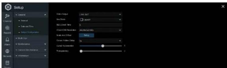
text_image
Setup User Output View Out Speed Capacity SCL1: Digital Time VGA/HCM Resolution Audio/Audio/Quality Scale And Offset Setup Current Hellen Delay Color Succession Transparency 5 2USER MANUAL
VGA/HDMI Resolution: Select a display resolution that is suitable for the monitor or TV. 1920 x 1080 will suit most displays. If the monitor supports 4K resolution, select either 2K (2560 x 1440) or 4K (3840 x 2160) to take advantage of the higher resolution.
Scale and Offset: The NVR supports adjusting the size & position of the display screen to match the monitor or TV. Click Setup to adjust.
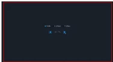
text_image
50% 30% 10%Scale: To adjust the size of the displayed screen by scale.
X Offset: To move the displayed screen to left or right.
Y Offset: To move the displayed screen to up or down.
Click once or long press the left button of the mouse on the arrow to adjust the size and position. The scroll wheel of the mouse can also be used. Click the right button of the mouse to exit and then click Apply to save the modifications.
Cursor Hidden Delay: Click the drop-down menu to select the time the NVR will hide the mouse cursor when idle. This can be disabled by selecting "OFF".
Cursor Acceleration: To adjust the speed of the mouse cursor.
Transparency: Click and hold the slider left or right to change how transparent the Menu Bar and

text_image
File File Type: Normal Normal Normal Normal Normal Normal Normal Normal Normal Normal Normal Normal Normal Normal Normal Normal Normal Normal Normal Normal Normal Normal Normal Normal Normal Normal Normal Normal Normal Normal Normal Normal Normal Normal Normal Normal Normal Normal Normal Normal Normal Normal Normal Normal Normal Normal Normal Normal Normal Normal Normal NeutralThe system supports the following account types:
- ADMIN — System Administrator: The administrator has full control of the system, and can change both administrator and user passwords and enable/disable password protection.
- USER — Normal User: Users only have access to live viewing, search, playback, and other functions. Specific permissions can be granted to individual users.
5.6.3.1 Changing Password
To change the password for the administrator or user accounts, click the User Edit icon 📋. The password must have 8 characters and can contain a mixture of numbers and letters. Enter the new password again to confirm, and then click Save to save the new password. The old password will need to entered to authenticate.
USER MANUAL
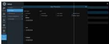
5.6.3.2 Add New Users

text_image
Setup File Edit View Insert Tools Help Tools Help Tools Help Tools Help Tools Help Tools Help Tools Help Tools Help Tools Help Tools Help Tools Help Tools Help Tools Help Tools Help Tools Help Tools Help Tools Help Tools Help Tools Help Tools Help Tools Help Tools Help Tools Help Tools Help Tools Help Tools Help Tools Help Tools Help Tools Help Tools Help Tools Help Tools Help Tools Help Tools Help Tools Help Tools Help Tools Help Tools Help Tools Help Tools Help Tools Help Tools Help Tools Help Tools Help Tools Help Tools Help Tools Help Tools Help Tools Help Tools Help Tools help OK Cancel Help Help Help Help Help Help Help Help Help Help Help Help Help Help Help Help Help Help Help Help Help Help Help Help Help Help Help Help Help Help Help Help Help Help Help Help Help Help Help Help Help Help Help Help Help Help Help Help Help Help Helding Time (20:00) Help- Select one of the user accounts that is currently disabled and then click the User Edit icon 📋.

text_image
User Edit Level USER1 User Profile Enable User Name void Password Enable Enable Password ******** System ******** Show Password Show Password Default Save Cancel5.6.3.3 Setting User Permissions
The administrator account is the only account that has full control of all system functions. Specific functions can be enabled or disabled for every user account.

text_image
Setup File Edit View Insert Tools Help Tools Help Tools Help Tools Help Tools Help Tools Help Tools Help Tools Help Tools Help Tools Help Tools Help Tools Help Tools Help Tools Help Tools Help Tools Help Tools Help Tools Help Tools Help Tools Help Tools Help Tools Help Tools Help Tools Help Tools Help Tools Help Tools Help Tools Help Tools Help Tools Help Tools Help Tools Help Tools Help Tools Help Tools Help Tools Help Tools Help Tools Help Tools Help Tools Help Tools Help Tools Help Tools Help Tools Help Tools Help Tools Help Tools Help Tools Help Tools Help Tools Help Tools help 1.0000 2.0000 3.0000 4.0000 5.0000 6.0000 7.0000 8.0000 9.0000 10.0000 11.0000 12.0000 13.0000 14.0000 15.0000 16.0000 17.0000 18.0000 19.0000 20.0000 21.0000 22.0000 23.0000 24.0000 25.0000 26.0000 27.0000 28.0000 29.0000 30.0000 31.0000 32.0000 33.0000 34.0000 35.0000 36.0000 37.0000 38.0000 39.0000 40.0000 41.0000 42.0000 43.0000 44.0000 45.0000 46.0000 47.0000 48.0000 49.0000 50.0000 51.0000 52.0000 53.0000 54.0000 55.0000 56.0000 57.0000 58.0000 59.0000 60.000- Click the edit icon under the Permission tab.
text_image
Screenshot of a software interface showing a dropdown menu with Chinese options and a grid of data fields.5.6.4 Maintenance
In this section, the available parameters are: system log, factory default, firmware upgrade, export & import system parameters, and system auto reboot.
text_image
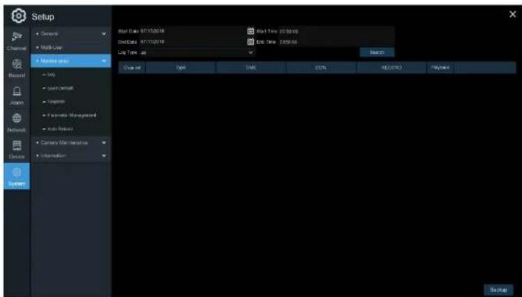
Setup Channel Multi-User Network Local Local Default Ethernet System Management Auto Protocol Camera Main Network Information Reset Data: 01/17/2018 Grid Data: 01/17/2018 Link Data: 01/17/2018 Reset Time: 02:30:00 End Time: 24:05:04 Reset Channel Type TIME JSON REPORTS Payback System5.6.4.1 Log
The system log shows important system events, such as motion alarms and system warnings.
USER MANUAL
text_image
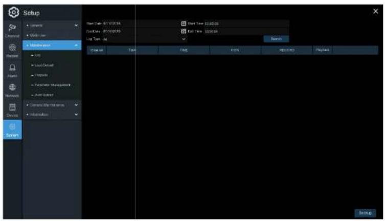
Setup • Console • Web User • Maintenance • Help • Local/Default • Upgrade • Parameters Management • Auto-Printout • Current Mode Features • Information Start Date: 07/15/2018 End Date: 07/15/2019 Log Type: All Start Time: 3:20:26 End Time: 3:30:36 Launch Type TIME CEN REPORTS Systems SystemLog Searching and Backing Up:
- Click the field next to Start Date &Start Time to choose the starting date & time.
- Click the field next to End Date & End Time to choose the end date & time.
USER MANUAL
- Click Backup to create a backup of the system log for the search period. Please make sure the flash drive has been connected to the NVR's USB port.
- When the backup drive menu appears, navigate to the folder for the backup file to be saved in, and then click OK to begin.
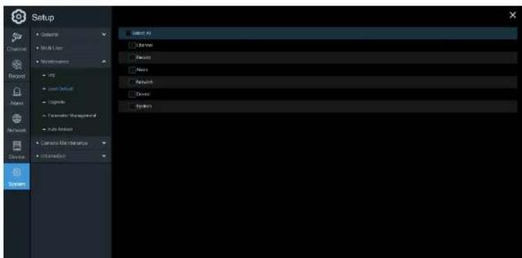
5.6.4.2 Load Default
Reset the NVR settings to its factory default state. Restoring default settings will not delete recordings and snapshots saved to the hard drive.
text_image
Setup Camera Multi-Large Maintenance USB Load Default Cognitive Parameter Management Auto Assist Current Mode Instance Information Select All Libraries Desktop Maps Network Device Parameters5.6.4.3 Upgrade

text_image
Setup • Gettart • Myk-Lien • Microsoft • Help • View (Actual) • Update • Expressor (User)... • Next Update • Camera User Interface • Transaction Update File Path: USB1.1 Name Last Entity Dock and Embedded Not Selected Localities Benedict Files Formal Between Hosted Cancel- Copy the firmware file (.sw file) to the USB flash drive and insert the flash drive into the NVR's USB port.
- Click the Select File button to choose the firmware file in the USB flash drive, and then Click OK.
- Click the Upgrade button to start the system upgrade. The system upgrade will last around 5-10
USER MANUAL

text_image
Screenshot of a software interface with menu options and a toolbar, likely from an older application or game.Save Settings: Click to save the NVR current system settings to the USB flash drive. Enter the Admin password to authenticate.
Load Settings: Click Load Settings button to navigate to the system settings file to import from the USB flash drive. Enter the Admin password to authenticate.
5.6.4.5 Auto Reboot
This menu allows the system to auto reboot the NVR regularly.
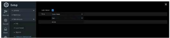
text_image
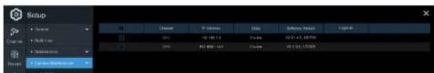
Setup Auto Hadoop Time: Auto Hadoop Time: 00:005.6.5 Camera Maintenance
For the IP camera that was included within the system, this menu allows IP camera's firmware to be updated and the default settings to be restore.

text_image
Setup Source Multi-Link Networks Edit Save As/Restore... Save As/Restore... Save As/Restore... Save As/Restore... Save As/Restore... Save As/Restore... Save As/Restore... Save As/Restore... Save As/Restore... Save As/Restore... Save As/Restore... Save As/Restore... Save As/Restore... Save As/Restore... Save As/Restore... Save As/Restore... Save As/Restore... Save As/Restore... Save As/Restore... Save As/Restore... Save As/Restore...5.6.5.1 Upgrade IP Camera
text_image
Setup Normal Normal Normal Normal Normal Normal Normal Normal Normal Normal Normal Normal Normal Normal Normal Normal Normal Normal Normal Normal Normal Normal Normal Normal Normal Normal Normal Normal Normal Normal Normal Normal Normal Normal Normal Normal Normal Normal Normal Normal Normal Normal Normal Normal Normal Normal Normal Normal Normal Normal NeutralUSER MANUAL
- Click the camera Upgrade button to start the upgrade. Enter the Admin password to authenticate. Do NOT power off the NVR and IP camera or remove the USB during the process.
5.6.5.2 Load Default Settings for IP Camera
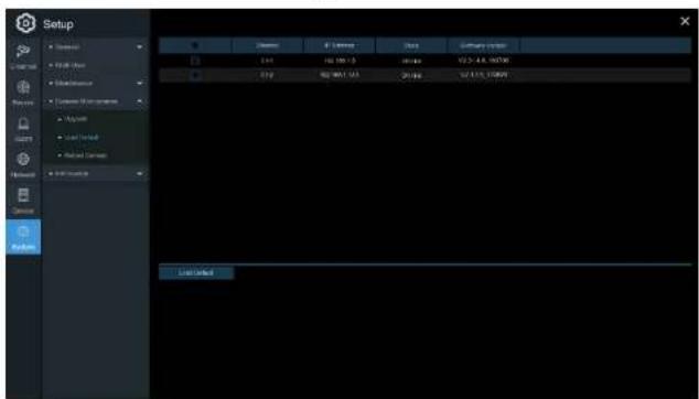
text_image
Setup File Name: 100000000 File Size: 100000000 File Type: Normal File Region: Normal File Date: 2019-04-23 Load Default- Choose the IP cameras to restore back to factory settings.
- Click Load Default to restore settings. Enter the Admin password to authenticate.
5.6.6 System Information
USER MANUAL

text_image
Setup Device ID: 032000 Device Name: N4564 Device Type: N4564 Hardware Version: 202-207 Software Version: 106.1.8/106.1.19 E-Client Version: 024-0.113 Video Format: FSL HOLD Video: 98830 IP Address: 192.162.1.192 Deep Port: No Client Port: 9000 MAC Display: 05-11-20-23-CR41 Network Status: ordered status POP ID: RGS-170723-002-081Scan the QR code on this page with the Speco Gray mobile app to remotely view the NVR.
5.6.6.2 Channel Information

text_image
Setup File Edit View Help Add Options Edit View Insert Tools Remove Tools Help Add 1.0 1.5 2.0 2.5 3.0 3.5 4.0 4.5 5.0 5.5 6.0 6.5 7.0 7.5 8.0 8.5 9.0 9.5 10.0 10.5 11.0 11.5 12.0 12.5 13.0 13.5 14.0 14.5 15.0 15.5 16.0 16.5 17.0 17.5 18.0 18.5 19.0 19.5 20.0 20.5 21.0 21.5 22.0 22.5 23.0 23.5 24.0 24.5 25.0 25.5 26.0 26.5 27.0 27.5 28.0 28.5 29.0 29.5 30.0 30.5 31.0 31.5 32.0 32.5 33.0 33.5 34.0 34.5 35.0 35.5 36.0 36.5 37.0 37.5 38.0 38.5 39.0 39.5 40.0 40.5 41.0 41.5 42.0 42.5 43.0 43.5 44.0 44.5 45.0 45.5 46.0 46.5 47.0 47.5 48.0 48.5 49.0 49.5 50.0 50.5 51.0 51.5 52.0 52.5 53.0 53.5 54.0 54.5 55.0 55.5 56.0 56.5 57.0 57.5 58.0 58.5 59.0 59.5 60.0 60.5 61.0 61.5 62.0 62.5 63.0 63.5 64.0 64.5 65.0 65.5 66.0 66.5 67.0 67.5 68.0 68.5 69.0 69.5 70.0USER MANUAL
5.6.6.3 Record Information

text_image
Screenshot of a software interface with menu bar, toolbar, and status bar showing file path and status informationView recording information for each connected camera such as bit rate, stream type, recording resolution and frame rate (FPS).
5.6.6.4 Network State

text_image
Setup C:\Users\Mull-User Mac OSOS Current Maintenance MOSO Application External Interface Security Network File Path Layer Path HKEY Path URL IP Address 100 100.1 146 Subram Mask 258 229.358.2 Disarray 199.108.1.1 MAC Address 60.11.22.27 DRAT DHUP Address Internal Interface IP Address 10.10.23.109 Subram Mask 254.00.00.09 DNG 201.4.31.146 DHRS 8.4.0.9 Format Format Web Port 62 Layer Port 58/00 HKEY Port 64Chapter 6 Search, Playback & Backup
The Search function provides the ability to search for and play previously recorded videos as well as snapshots that are stored on the NVR's hard drive. There is a choice of playing video that matches the recording schedule, manual recordings or motion events only. The Backup function provides the ability to save important events (both video and snapshots) to a USB flash drive.
6.1 Using Search Function
Click Search in the Start Menu to enter search section.

text_image
Search Date: 2024-07-01 Channel Type: Verse: Motion Power Type: Web Stream Chamber: Ctrl CX3 CX5 USS 1 2 3 4 7- Video Playback Controls: to control the video playback.

Enlarge the video playback to full screen
Rewind, x2, x4, x8 and x16
Slow Play, 1/2, 1/4 and 1/8, 1/16 speed
Play
00 Pause
Play frame by frame. Click once to play a frame of the video
□ Stop
Fast Forward, x2, x4, x8 and x16
Snapshots: to capture a snapshot image to a USB flash drive. If the video playback is in split-screen view, select the channel to capture, and then click the icon to save the snapshot.
- Timeline: R recordings are shown with colored bars to represent different types of recording (legend shown in the bottom-right corner of the display). Use the time frame options
(○ 24h ● 2h ● 1h ● 30m) to view a smaller or larger time period.
Different types of recording shown in different colors:
Continuous Recording in Green color;
Motion Recording in Yellow color;
- Playback Status: displays the video playback status.
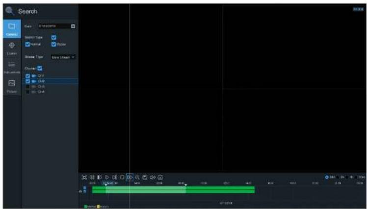
6.1.1 Search & Play Video in General
This menu gives an option to search & play recording for a selected date.
USER MANUAL
text_image
Search Date: 01/03/2017 Search Type: Normal Normal Show Type: Up to Draw... Change: CH1 CH2 CH3 CH4 Chase 0.000 0.000 0.000 0.000 0.000 0.000 0.000 0.000 0.000 0.000 0.000 0.000 0.000 0.000 0.000 0.000 0.000 0.548 12.16 9.12 11.16 15.16- Select a date to search for video recording from the calendar. Dates with recordings will be underlined.
- Choose a search type.
- Check channels to search, or check Channel to search all connected channels.
- The search result will display on the timeline from 00:00 to 24:00.
6.1.1.1 Video Clip Backup

text_image
Screenshot of a video editing timeline interface showing tracks, clips, and playback controls- Insert the USB flash drive to the NVR.
- Start a playback.
- Click the icon.
- Check the desired channel(s).
- Move the mouse cursor to the time where the clip should start.
- Click and drag the cursor to the time where the clip should end.
- Click ☐ to save the video clip.
- Select a file type for the backup files and then click the Save button to save the video clips. Make sure the USB drive has enough space to save the video clips.

USER MANUAL
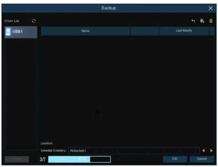
text_image
Backup Driver List USB1 Name Last Modify Location Selected Directory: /rdev/usb1 3/7 4.0 OK Cancel6.1.2 Event Search, Playback & Backup

text_image
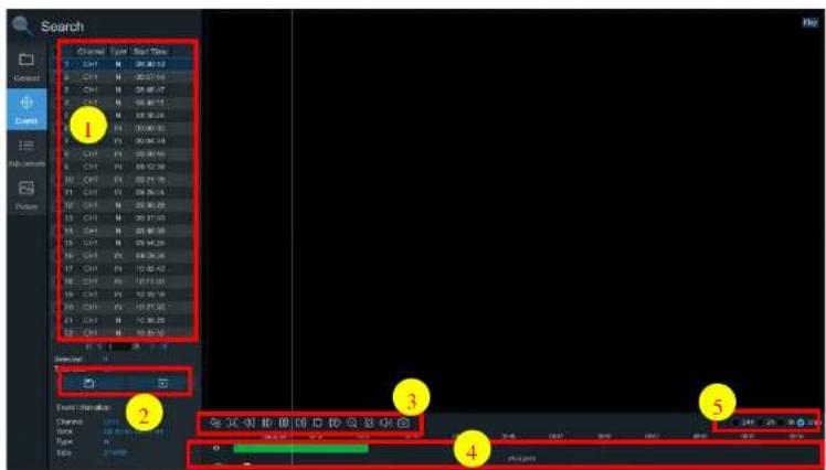
Search 1 Eave C: 300deg Time: 00:00:00 23:50:00 2 Sewert Type Normal Normal Show Type Show ID 3 Chronic CHF CHD CHD CHD 4 Event Management Start Time: 00:00:00 23:50:00 End Time: 00:00:00 9 11 10 7 Detailed line Selected Selected to Take Start / Add Driver TypeTo search, play & back up for events:
- Choose the date & time to search.
USER MANUAL

Thumbnails view. View the snapshots of the events.

Detailed view. Details of the events will be listed.
| Channel | Time | Date | Start Time | End Time | Size | Finish | Unit | |
| 1 | CHI | MMS | 00:29:17 | 00:00:3 | 00:45:45 | MM | ☐ | ☐ |
| 2 | CHI | MMS | 00:29:17 | 00:00:45 | 00:18:05 | 75W/B | ☐ | ☐ |
| 3 | CHI | MMS | 00:29:17 | 01:15:33 | 01:44:13 | 517W/B | ☐ | ☐ |
| 4 | CHI | MMS | 00:29:17 | 00:44:00 | 01:16:08 | 207W/B | ☐ | ☐ |
| 5 | CHI | MMS | 00:29:17 | 01:13:08 | 01:19:22 | CM/B | ☐ | ☐ |
| 6 | CHI | MMS | 00:29:17 | 01:19:22 | 01:35:37 | SM/B | ☐ | ☐ |
| 7 | CHI | MMS | 00:29:17 | 01:25:37 | 01:41:33 | SM/B | ☐ | ☐ |
| 8 | CHI | MMS | 00:29:17 | 01:43:02 | 02:01:52 | 199W/B | ☐ | ☐ |
| 9 | CHI | MMS | 00:29:17 | 02:01:12 | 02:15:38 | 207W/B | ☐ | ☐ |
| 10 | CHI | MMS | 00:29:17 | 02:25:36 | 02:41:17 | 199W/B | ☐ | ☐ |
| 11 | CHI | MMS | 00:29:17 | 02:41:31 | 02:52:09 | 199W/B | ☐ | ☐ |
| 12 | CHI | MMS | 00:29:17 | 03:02:28 | 03:38:37 | 32W/B | ☐ | ☐ |

List view. Displays the list of the events.
| 1 | CHI | 001207 | 12 | CHI | 00245 | 13 | CHI | 10 0630 | 4 | CHI | 00345 | 5 | CHI | 111948 | 6 | CHI | 01250 | 7 | CHI | 01368 | 8 | CHI | 01420 |
| 11 | CHI | 001122 | 15 | CHI | 00258 | 11 | CHI | 04117 | 12 | CHI | 10128 | 13 | CHI | 110698 | 14 | CHI | 01301 | 15 | CHI | 01314 | 16 | CHI | 00427 |
| 12 | CHI | 002223 | 16 | CHI | 00125 | 10 | CHI | 26 2031 | 20 | CHI | 15 0030 | 21 | CHI | 25 3412 | 22 | CHI | 01355 | 23 | CHI | 003617 | 24 | CHI | 001628 |
| 12 | CHI | 001613 | 16 | CHI | 00435 | 12 | CHI | 7 0018 | 20 | CHI | 12 0018 | 20 | CHI | 13 0138 | 16 | CHI | 004614 | 17 | CHI | 001751 | 18 | CHI | 004714 |
| 12 | CHI | 001524 | 18 | CHI | 00370 | 16 | CHI | 25 2117 | 18 | CHI | 10 0218 | 17 | CHI | 26 0528 | 20 | CHI | 001812 | 19 | CHI | 001818 | 20 | CHI | 10 1342 |
| 12 | CHI | 003537 | 19 | CHI | 11 1248 | 14 | CHI | 11 2087 | 14 | CHI | 11 0149 | 16 | CHI | 12 0928 | 18 | CHI | 12 0817 | 20 | CHI | 12 0445 | 21 | CHI | 12 0818 |
| 12 | CHI | 110938 | 20 | CHI | 11 0335 | 15 | CHI | 13 0315 | 12 | CHI | 12 0510 | 15 | CHI | 12 0334 | 18 | CHI | 12 1118 | 21 | CHI | 12 1013 | 22 | CHI | 12 0926 |
| 12 | CHI | 110421 | 20 | CHI | 14 0442 | 16 | CHI | 14 0408 | 10 | CHI | 15 0346 | 16 | CHI | 13 0302 | 22 | CHI | 16 0378 | 22 | CHI | 16 0378 | 24 | CHI | 16 0624 |
| 12 | CHI | 002225 | 20 | CHI | 00341 | 18 | CHI | 15 0335 | 18 | CHI | 15 0314 | 18 | CHI | 12 0812 | 23 | CHI | 11 0830 | 23 | CHI | 11 0830 | 24 | CHI | 10 0835 |
| 12 | CHI | 001807 | 24 | CHI | 00414 | 19 | CHI | 15 0314 | 17 | CHI | 15 0327 | 17 | CHI | 12 0812 | 25 | CHI | 15 0538 | 25 | CHI | 15 0538 | 26 | CHI | 001247 |
| 12 | CHI | 003040 | 26 | CHI | 00345 | 19 | CHI | 15 0308 | 16 | CHI | 26 0031 | 18 | CHI | 21 0128 | 26 | CHI | 21 0128 | 26 | CHI | 21 0128 | 27 | CHI | 22 0048 |
| 12 | CHI | 001898 | 28 | CHI | 00364 | 20 | CHI | 15 0342 | 18 | CHI | 26 0739 | 18 | CHI | 21 0048 | 28 | CHI | 22 0038 | 28 | CHI | 22 0038 | 29 | CHI | 003656 |
- When an event is selected, the event information will be shown on the bottom left corner of the
6.1.2.1 Event Playback Control
text_image
Search Channel Type Stop Time 1 CHY N 26.82.13 2 CHY N 00:57.94 3 CHY N 09:48.47 4 CHY N 09:48.11 5 CHY N 09:30.28 6 CHY N 00:00.35 7 CHY N 00:04.14 8 CHY N 00:30.90 9 CHY N 09:12.28 10 CHY N 09:21.16 11 CHY N 09:26.14 12 CHY N 09:30.29 13 CHY N 09:37.53 14 CHY N 09:40.36 15 CHY N 09:45.26 16 CHY N 09:50.26 17 CHY N 10:02.43 18 CHY N 10:13.01 19 CHY N 10:27.36 20 CHY N 10:30.29 21 CHY N 10:35.56 Event Options: Channels: SWEI, VSS, WSS, CCKS, DSS, ESS, FSS, GSS, HSS, ISS, JSS, KSS, LSS, MSS, NSS, OSS, PSS, QSS, RSS, SSS, TSS, USS, VSS, WSS, XSS, YSS, ZSS, AASS, ABSS, ACSS, ADSS, AESS, AFSS, AGSS, AHSS, AISS, AJSS, AKSS, ALSS, AMSS, ANSS, AOSS, APSS, AQSS, ARSS, ASSS, ATSS, AUSS, AVSS, AWSS, AXSS, AXXSS, AZSS, BASS, BBSS, BCSS, BDSS, BESS, BFSS, BGSS, BHSS, BISS, BJSS, BKSS, BLSS, BMSS, BNSS, BOSS, BPSS, BPSX, BPSX, CCXXXXXXXXXXXXXXXXXXXXXXXXXXXXXXXXXXXXXXXXXXXXXXXXXXXXXXXXXXXX Chronic State: 0 Type: 1 Balance: 27 mm Sequence: 1 Event Options: Channels: SWEI VSS WSS CCKS DSS ESS FSS GSS HSS ISS JSS KSS LSS MSS NSS OSS PSS QSS RSS SSS TSS USS VSS WSS XSS AXXSS ABXXS ACXXS AFXXS BXXS BCXXS BDXXS BEXXS BFXXS AGXXS BAXXS ACXXS AXXXS ABXXS CAXXS BDXXS BEXXS BFXXS AGXXS BAXXS ACXXS AXXXS ABXXS CAXXS AXXXS DAXXS ABXXS CAXXS BAXXS AGXXS BAXXS ACXXS AXXXS ABXXS CAXXS AXXXS- Event List. Select events from here.
- Click ☐ to save selected event clips to a USB flash drive. Click ☐ to play the video.
- Control the playback with buttons on Video Playback Controls. Click right-click on the mouse to exit playback and return to the event search window.
USER MANUAL

text_image
Search 1 2 3 4 5 6 7 8To search & play video in sub-periods:
- Choose the date & time.
- Choose the number of split-screens to play the videos in.
- Check the recording types to search for, or check Search Type to choose all.
- Choose the channels to search. Please note that this function only supports to search & play one
USER MANUAL
- Use the time frame options (○ 24h ● 2h ● 1h ● 30m) to view a smaller or larger time period.
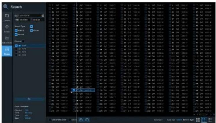
6.1.4 Picture Search & View
Search and view snapshots.

text_image
Search 1 Date: 07/03/2024 Time: 06:00:00 Search Type: Normal Normal Close Close Close Close Close Close Close Close Close Close Close Close Close Close Close Close Close Close Close Close Close Close Close Close Close Close Close Close Close Close Close Close Close Close Close Close Close Close Close Close Close Close Close Close Close Close Close Close Close Close CCT-10000000000000000000000000000000000000000000000000000000000000000000000000000000000000000000000000000 1 2 3 4 5 6 7 8 9 11 12 13 14 15 16 17 18 19 20 21 22 23 24 25 26 27 28 29 30 31 32 33 34 35 36 37 38 39 40 41 42 43 44 45 46 47 48 49 50 51 52 53 54 55 56 57 58 59 60 61 62 63 64 65 66 67 68 69 70 71 72 73 74 75 76 77 78 79 80 81 82 83 84 85 86 87 88 89 90 91 92 93 94 95 96 97 98 99 100USER MANUAL
-
Click in the bottom-right corner of the menu to browse between pages of pictures, or enter the specific page.
-
Switch between different views by clicking on the icons at the right bottom corner of the screen:


Thumbnails view. Displays the thumbnails of the events.

List view. The events will be displayed in list.
| 1 | 6 | CH | 20/12 | 10 | CH | 20/13 | 12 | CH | 02/08 | 13 | CH | 03/07 | 14 | CH | 03/05 | 15 | CH | 03/04 |
| 17 | CH | 20/12 | 10 | CH | 20/13 | 12 | CH | 02/08 | 13 | CH | 03/07 | 14 | CH | 03/05 | 15 | CH | 03/04 | |
| 17 | CH | 20/12 | 10 | CH | 20/13 | 12 | CH | 02/08 | 21 | CH | 03/07 | 15 | CH | 03/05 | 21 | CH | 03/04 | |
| 17 | CH | 20/12 | 10 | CH | 20/13 | 12 | CH | 02/08 | 21 | CH | 03/07 | 15 | CH | 03/05 | 21 | CH | 03/04 | |
| 17 | CH | 20/12 | 10 | CH | 20/12 | 12 | CH | 02/08 | 21 | CH | 03/07 | 15 | CH | 03/05 | 21 | CH | 03/04 | |
| 17 | CH | 20/12 | 10 | CH | 20/12 | 12 | CH | 02/08 | 21 | CH | 03/07 | 15 | CH | 03/12 | 21 | CH | 03/12 | |
| 17 | CH | 20/12 | 10 | CH | 20/12 | 12 | CH | 02/08 | 21 | CH | 03/07 | 15 | CH | 03/12 | 21 | CH | 03/12 | |
| 17 | CH | 20/12 | 10 | CH | 20/12 | 12 | CH | 03/08 | 21 | CH | 03/07 | 15 | CH | 03/12 | 21 | CH | 03/12 | |
| 17 | CH | 20/12 | 10 | CH | 20/12 | 12 | CH | 03/08 | 21 | CH | 03/07 | 15 | CH | 03/12 | 21 | CH | 12/12 | |
| 17 | CH | 20/12 | 10 | CH | 20/12 | 12 | CH | 03/08 | 21 | CH | 03/07 | 15 | CH | 03/12 | 21 | CH | 12/12 | |
| 17 | CH | 20/12 | 10 | CH | 20/12 | 12 | SH | 03/08 | 21 | CH | 03/07 | 15 | CH | 03/12 | 21 | CH | 12/12 | |
| 17 | CH | 20/12 | 10 | CH | 20/12 | 12 | SH | 03/08 | 21 | CH | 03/07 | 15 | CH | 03/12 | 21 |

Detailed view. Displays the details of the files.
| Channel | Type | Date | Time | Size | Playback | |
| 1 | CHI | MIN | 10/24/2017 | 00:00:00 | 160KB | |
| 2 | CHI | MIN | 10/24/2017 | 00:12:01 | 201KB | |
| 3 | CHI | MIN | 10/24/2017 | 00:21:20 | 401KB | |
| 4 | CHI | MIN | 10/24/2017 | 00:24:36 | 111KB | |
| 5 | CHI | MIN | 10/24/2017 | 00:37:25 | 167KB | |
| 6 | CHI | MIN | 10/24/2017 | 00:55:58 | 210KB |
- Select a file to display the picture information on the bottom left corner of the screen.
6.1.4.1 Picture Preview Control
text_image
Search Time: 04:28:00 17:35:59 Search Type: Name: ST-00000000 Name: ST-00000000 Channel: Cell C4S C4S C4S C4S C4S C4S C4S C4S C4S C4S C4S C4S C4S C4S C4S C4S C4S C4S C4S C4S C4S C4S C4S C4S C4S C4P C4P C4P C4P C4P C4P C4P C4P C4P C4P C4P C4P C4P C4P C4P C4P C4P C4P C4P C4P C4P C4P C4P C4P C4P C4T C4T C4T C4T C4T C4T C4T C4T C4T C4T C4T C4T C4T C4T C4T C4T C4T C4T C4T C4T C4T C4T C4T C4T C4T C4P C4P C4P C4P C4P C4P C4P C4P C4P C4P C4P C4P C4P C4P C4P C4P C4P C4P C4P C4P C4P C4P C4P C4P C4F C4F C4F C4F C4F C4F C4F C4F C4F C4F C4F C4F C4F C4F C4F C4F C4F C4F C4F C6A11111111111111111111111111111111111111111111111111111111111111111111111111111111111111111111111111110999999999999999999999999999999999999999999999999999999999999999999999999999999999999999999999999999988888888888888888888888888888888888888888888888888888888888888888888888888888888888888888888888888886666666666666666666666666666666666666666666666666666666666666666666666666666666666666666666666666666- Picture List - select the pictures here.
- Click ☐ to save selected pictures to a USB flash drive. Click ☐ to view the pictures in a slide show.
- Press Button to exit the preview control window and go back to the picture search window.
Chapter 7 Remote Access via Web Client
The NVR can be remotely accessed in various ways on a Windows PC or a Mac. The methods are as follows:
- Internal local network
- Internet Explorer using local IP address of NVR
- Speco Gray Viewer (included on CD or download) application using local IP address of NVR or P2P ID of NVR
- Speco Gray Viewer plug-in for Safari on Mac using local IP address or P2P ID
- External
- Internet Explorer: go to http://gray.specotech.com and enter P2P ID (note that with this method, system setup options will not be available)
- Internet Explorer using DDNS
o Speco Gray Viewer using P2P ID - Speco Gray Viewer plug-in for Safari on Mac using P2P ID or DDNS
| Display Resolution | 1280*1024 1920*1080 | |
| OS | Windows 7 or aboveMac OS X® 10.9 or above | |
| DirectX | DirectX 11 | |
| Direct3D | Acceleration Function | |
| Ethernet Adapter | 10/100/1000M Ethernet Adapter | |
| IE | Microsoft Internet Explorer (Ver. 11,10,9,8). | |
| Mac Safari | 5.1 or above | |
7.2 Web Plug-in Download and Installation
For IE:
- Launch IE on the PC and enter the NVR IP address or DDNS domain name (Host Name) in the address field.
-
When the client is run for the first time, the Active-X plug-in will need to be installed. Click
-
After installing the plug-in, close and launch the browser again, and repeat step 1 to open the login page. Enter the user name and password to log in.

text_image
speco technologies admin Password Remember Password LoginFor Mac Safari:
- Launch Safari and enter the NVR IP address or DDNS domain name (Host Name) in the address field.

USER MANUAL
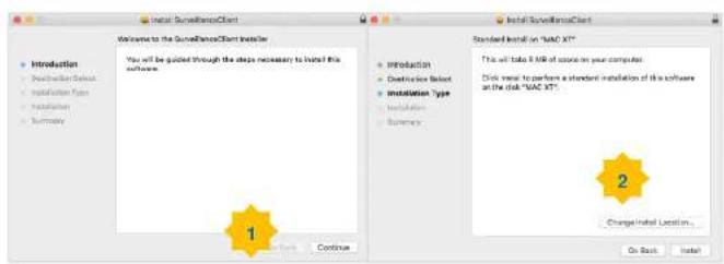
text_image
Welcome to the SurveillanceClient installed You will be guided through the steps necessary to install this software. 1 Standard Install on "MAC XT" This will take 8 KB of course on your computer. Click insert to perform a standard installation of this software at the disk "MAC XT" 2 Change Install Location... On Back Install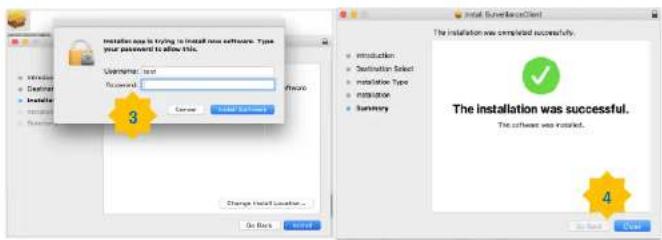
text_image
Installation use is trying to install new software. Type your password to allow this. Username: test Successful: Cancel Install Save Change Install location... Go Back Install Place 3 Remove Install Save Install Cancel Install Save Install Install Install Install Install Install Install Install Install Install Install Install Install Install Install Install Install Install Install Install Install Install Install Install Install Install Install Install Install Install Install Install Install Install Install Install Install Install Install Install Install Install Install Install Install Install Install Install Install Install Technological Service The installation was completed successfully. Introduction: Destination Select: Instaliation Type: Instruction: Summary: The installation was successful. The software was installed. 4- Close Safari and open it again to repeat step 1 to open the Web Client login page.
USER MANUAL
7.3 Web Client Manager
The system can be fully controlled through the web client interface.
7.3.1 Live Interface

text_image
Live Playback Remote Settings Computer Settings Close-up Main Stream Sub Stream Mobile Stream 7 8USER MANUAL
Manual snapshot button. Click to save a snapshot of the current live display to the computer.
Bitrate button. Set camera to use the main stream, sub stream or mobile stream..
2- Live Video Stream Options:
Main stream: View all live videos using high-quality main stream video settings.
Sub stream: View all live videos using middle-quality sub stream video settings.
Mobile Stream: View all live video using lower-quality mobile stream video settings to conserve bandwidth.
3- Main Menus:
Live: View live video from cameras.
Playback: View recorded video which is saved on the NVR's HDD.
Remote Setting: Access the NVR system settings.
Local Settings: Set download locations for recordings and snapshots taken using the Web Client, and choose the file type for video files.
4- Information: Hover over to see system details.
5- Exit.
7- Live View Control Buttons:


Open the images on Live window.

Close all Live channels

Original Proportions: Shows live video at the original proportions

Stretch: Stretch live video to fit the full area for each channel on screen.

To enlarge the web client to full screen.

Manual Recording: Click to start manually recording for all displayed channels. Click again to recording. Manual recordings are saved to the computer.

Snapshot: Click to save snapshots of all current displayed channels to the computer.

Digital Zoom: Click on a live image, then click-and-drag over an area of the live image to range. Right-click to return to the normal display.

Volume Control. Volume mute.
8- Page View: Click to select how many channels appear on the screen at a time.
7.3.2 Playback
Search & play recording videos stored on the HDD of the NVR, and download the videos to the computer.
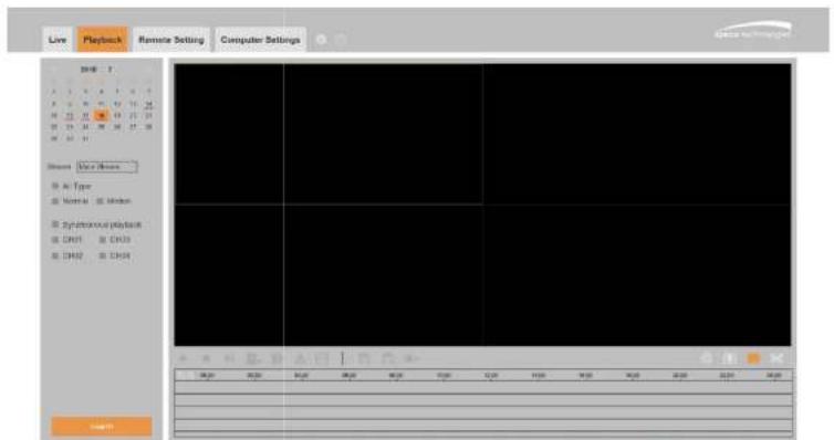
text_image
Live Playback Remote Setting Computer Settings 2018 A 3 4 5 6 7 B 8 9 10 11 12 13 14 H 15 16 17 18 19 20 21 22 M 23 24 25 26 27 28 W 33 34 35 36 37 Status: New Status Air Type Normal Normal Synchrony playback CH01 CH02 CH03 CH04 CH05 18:20 20:20 21:20 22:20 23:20 24:20 18:20 20:20 21:20 22:20 23:20To search recordings:
- Click Playback in the top-right corner of the window.
- Select a day on the calendar to search for recordings from: Days with recordings appear with a
USER MANUAL
7.3.2.1 Playback Control Buttons
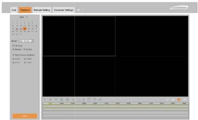
text_image
Live Playback Remote Setting Computer Settings 2018 Show: Live Event all type Internal Motion Electronics project CHD4 CHD3 Punch Play OKPlay the recordings
Pause
61-
USER MANUAL
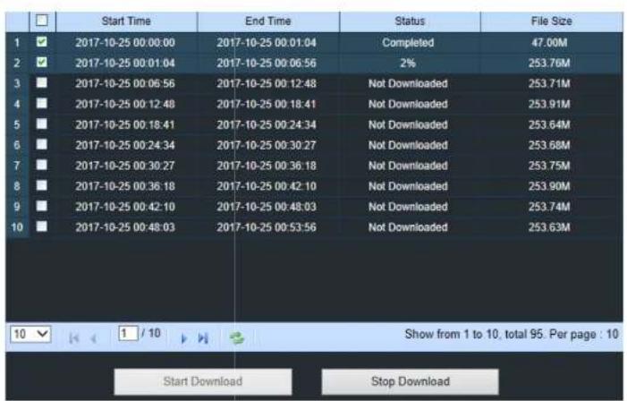
text_image
Start Time End Time Status File Size 1 ✓ 2017-10-25 00:00:00 2017-10-25 00:01:04 2017-10-25 00:06:56 2% 253.76M 3 ■ 2017-10-25 00:06:56 2017-10-25 00:12:48 Not Downloaded 253.71M 4 ■ 2017-10-25 00:12:48 2017-10-25 00:18:41 Not Downloaded 253.91M 5 ■ 2017-10-25 00:18:41 2017-10-25 00:24:34 Not Downloaded 253.64M 6 ■ 2017-10-25 00:24:34 2017-10-25 00:30:27 Not Downloaded 253.68M 7 ■ 2017-10-25 00:30:27 2017-10-25 00:36:18 Not Downloaded 253.75M 8 ■ 2017-10-25 00:36:18 2017-10-25 00:42:10 Not Downloaded 253.90M 9 ■ 2017-10-25 00:42:10 2017-10-25 00:48:03 Not Downloaded 253.74M 10 ■ 2017-10-25 00:48:03 2017-10-25 00:53:56 Not Downloaded 253.63M Show from 1 to 10, total 95. Per page : 10 Start Download Stop DownloadChoose the files to download and press Start Download button to begin. The download status will show. Press Stop Download to stop.

Playback Speed. Click to choose the playback speed.

Play All Channels: Click to play all channels that were chosen. Only available when the
Synchronous playback option is not checked
USER MANUAL
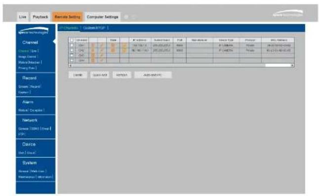
7.3.3 Remote Setting
Remotely configure the settings of the NVR. See "Chapter 5 NVR System Setup" for more details on the NVR settings..
text_image
Live | Playback | Remote Setting | Computer Settings SPC Channels | Custom FTP | □ Display □ Open □ Closed □ Print □ Printout □ Print □ Printout □ Print □ Printout □ Print □ Printout □ Print □ Printout □ Print □ Printout □ Print □ Printout □ Print □ Printout □ Print □ Printout □ Print □ Printout □ Print □ Printout □ Print □ Printout □ Print □ Printout □ Print □ Printout □ Print □ Printout ■ Print ■ Printout ■ Print ■ Printout ■ Print ■ Printout ■ Print ■ Printout ■ Print ■ Printout ■ Print ■ Printout ■ Print ■ Printout ■ Print ■ Printout ■ Print ■ Printout ■ Print ■ Printout ■ Print ■ Printout ■ Print ■ Printout ■ Print ■ Printout ■ Print ■ Printout ■ Print ■ PrintOUT ■ Print ■ PrintOUT ■ Print ■ PrintOUT ■ Print ■ PrintOUT ■ Print ■ PrintOUT ■ Print ■ PrintOUT ■ Print ■ PrintOUT ■ Print ■ PrintOUT ■ Print ■ PrintOUT ■ Print ■ PrintOUT ■ Print ■ PrintOUT ■ Print ■ PrintOUT ■ Print ■ PrintOUT ■ Print ■ PrintOUT ■ Print ■ PrintOUT □ Select □ Select Add □ Select Add □ Select Add □ Select Add □ Select Add □ Select Add □ Select Add □ Select Add □ Select Add □ Select Add □ Select Add □ Select Add □ Select Add □ Select Add □ Select Add □ Select Add □ Select Add □ Select Add □ Select Add □ Select Add □ Select Add □ Select Add □ Select Add □ Select Add □ Select Add □ Select + □ Select □ Select Add □ Select Add □ Select Add □ Select Add □ Select Add □ Select Add □ Select Add □ Select Add □ Select Add □ Select Add □ Select Add □ Select Add □ Select Add □ Select Add □ Select Add □ Select Add □ Select Add □ Select Add □ Select Add □ Select Add □ Select Add □ Select Add □ Select Add □ Select Add ▢ □ Select □ Select Add □ Select Add □ Select Add □ Select Add □ Select Add □ Select Add □ Select Add □ Select Add □ Select Add □ Select Add □ Select Add □ Select Add □ Select Add □ Select Add □ Select Add □ Select Add □ Select Add □ Select Add □ Select Add □ Select Add □ Select Add □ Select Add □ Select Add □ Select Add 100% □ Select □ Select Add □ Select Add □ Select Add □ Select Add □ Select Add □ Select Add □ Select Add □ Select Add □ Select Add □ Select Add □ Select Add □ Select Add □ Select Add □ Select Add □ Select Add □ Select Add □ Select + □ Select □ Select Add □ Select + □ Select □ Select + □ Select □ Select + □ Select □ Select + □ Select □ Select + □ Select □ Select + □ Select □ Select + □ Select □ Select + □ Select □ Select + □ Select □ Select + □ Select □ Select + □ Select □ Select + □ Select □ Select + □ Select □ Select + □ Select □ Select + □ Select ▢ □ Select + □ Select + Auto-SHPC7.3.4 Local Setting
Set download locations for recordings and snapshots taken using Web Client, and choose the file type for video files.
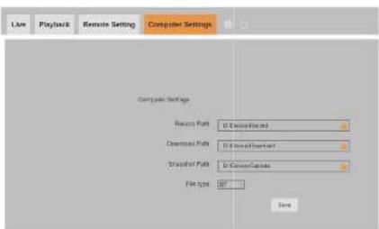
text_image
Live Playback Remote Setting Computer Settings Computer Settings Record Paths: D:\Users\Finds\ Download Paths: D:\Users\Finds\ Spread Paths: D:\Users\Capitals\ File type: NT OKRecord Path: Click to browse for and select the folder for the manual video recordings to be saved on the computer.
Download Path: Click to browse for and select the folder for the downloaded files to be saved on the computer.
Snapshot Path: Click to browse for and select the folder for the snapshots to be saved on the computer.
File Type: Choose the preferred file type for manual recordings.
Chapter 8 Viewing Exported Video on PC/Mac
Playing exported video files can be accomplished with the included video player. Install the video player that's on the CD. For Windows, choose the .exe file. For Mac, choose the .dmg file. After installation, follow the instructions below.
- Run the Video Player.
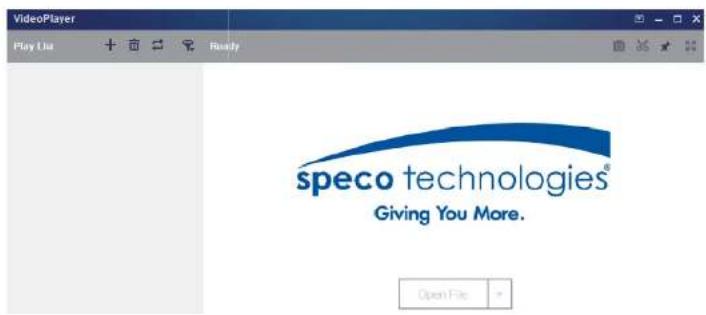
text_image
VideoPlayer Play List Ready speco technologies® Giving You More. Open FileUSER MANUAL
Video Player Control

text_image
VideoPlayer Play List IP CH211605.264 IP CH211605.264 IP CH211605.264 IP CH211605.264 IP CH211605.264 IP CH211605.264 IP CH211605.264 IP CH211605.264 IP CH211600.00.00.00.00.00.00.00.00.00.00.00.00.00.00.00.00.00.00.00.00.00.00.00.00.00.00.00.00.00.00.00.00.00.88 Play IP CH21172010 264 IPC 4MP 09/29/2017 11:30:12 5 1 2 3 4 1:1888 1 2 3 4- Play List

Add files
USER MANUAL
3. Play Controls

Play

Pause

Stop

Play frame by frame. Click once to play a frame of the video

Slow Play, 1/2, 1/4 and 1/8, 1/16 speed

Fast Forward, x2, x4, x8 and x16


Volume control

Multi-screen play. It allows for playing multiple videos simultaneously.

Take snapshot

Save a video clip to your computer. Press once to start, press again to end the video clip.

Keep the video player on top

Enlarge the video play screen to full screen

Advanced Setup Menu allows configuration of settings
USER MANUAL
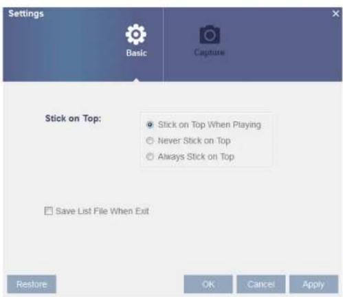
text_image
Settings Basic Capture Stick on Top: ● Stick on Top When Playing ○ Never Stick on Top ○ Always Stick on Top Save List File When Exit Restore OK Cancel ApplyBasic Settings: Set on-top mode

text_image
Settings Basic CaptureChapter 9 Appendix
9.1 Troubleshooting
- Q: What can I do if the system does not detect the HDD?
A: Check if the power supply system is properly connected and data cord and power cable are securely connected, and if something is wrong with the HDD interface.
- Q: I have changed the password but forgot the new password, how can I access the system?
A: Contact support for a password reset.
- Q: I see abnormal video signal or no video signal
A: Check the network cable connection at both the NVR side and the camera side to see if the cable is firmly connected to the port. Try a different cable and/or different PoE port if the problem persists.
- Q: How to prevent NVR from overheating?
A: The NVR needs to dissipate heat while it is running. Please place the NVR in a place with good air circulation and away from heat sources.
- Q: The remote control doesn't work.
USER MANUAL
A: Please check if the network connection settings are correct and RJ-45 port is with good contact. Check if the user credentials are correct.
- Q: Why can't I stop recording by pressing the "STOP" button or click "Stop Recording"?
A: Pressing Stop or Stop Recording can only stop manual record. If you want to stop Scheduled recording for specific time period, please change the schedule setting.