DNR408P2 - Security Camera FLIR - Free user manual and instructions
Find the device manual for free DNR408P2 FLIR in PDF.

User questions about DNR408P2 FLIR
0 question about this device. Answer the ones you know or ask your own.
Ask a new question about this device
Download the instructions for your Security Camera in PDF format for free! Find your manual DNR408P2 - FLIR and take your electronic device back in hand. On this page are published all the documents necessary for the use of your device. DNR408P2 by FLIR.
USER MANUAL DNR408P2 FLIR
natural_image
Front view of a black electronic device labeled 'FLIR' with control buttons and ports (no readable text beyond branding)
Instruction Manual
DNR400 SERIES
Thank you for purchasing this product. FLIR is committed to providing our customers with a high quality, reliable security solution.
This manual refers to the following models:
DNR408 (8-channel)
DNR416 (16-channel)
For the latest online manual, downloads and product updates, and to learn about our complete line of accessory products, please visit our website at:
www.flirsecurity.com/pro

WARNING
RISK OF ELECTRIC SHOCK DO NOT OPEN

WARNING: TO REDUCE THE RICK OF ELECTRIC SHOCK DO NOT REMOVE COVER. NO USER SERVICABLE PARTS INSIDE.
REFER SERVICING TO QUALIFIED SERVICE PERSONNEL.

The lightning flash with arrowhead symbol, within an equilateral triangle, is intended to alert the user to the presence of uninsulated "dangerous voltage" within the product's enclosure that may be of sufficient magnitude to constitute a risk of electric shock.

The exclamation point within an equilateral triangle is intended to alert the user to the presence of important operating and maintenance (servicing) instructions in the literature accompanying the appliance.
Table of contents
1 Important Safeguards ....1
1.1 General Precautions.... 1
1.2 Installation.... 1
1.3 Service 3
1.4 Use....3
2 DNR400 Series Features....4
3 Getting Started (DNR400 Series) 5
4 DNR400 Series Front Panel....6
5 Rear Panel (DNR400 Series) 7
6 Basic Setup (DNR400 Series)....8
6.1 Step 1: Connect the IP Cameras ....8
6.2 Step 2: Connect the Mouse....8
6.3 Step 3: Connect the Ethernet Cable 8
6.4 Step 4: Connect the Monitor....8
6.5 Step 5: Connect the Power Cable to Power the NVR....9
6.6 Step 6: Upgrade Firmware to Latest Version (if Available) 9
6.7 Step 7: Verify Camera Image 9
6.8 Step 8: Set the Time 10
6.9 Default System Password & Port Numbers 10
6.9.1 FLIR Cloud™ 10
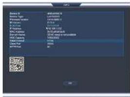
6.10 Quick Access to System Information 10
6.11 Connecting Cameras to the Local Area Network (LAN) 12
7 Mouse Control 15
8 Remote Control 16
8.1 Setting the Remote Control Address 17
9 Using the System 18
9.1 On-Screen Display 18
9.2 Using the Quick Menu.... 19
9.3 Adjusting Camera Image Settings.... 19
9.4 Using the Navigation Bar 21
Table of contents
13.3 Using Video Clip Backup 31
13.4 Viewing Backup Files 32
13.4.1 Viewing Backup Files on PC 32
13.4.2 Viewing Backup Files on Mac 35
14 Managing Passwords and User Accounts.... 38
14.1 Changing Passwords.... 38
14.2 Adding Users 38
14.3 Modifying Users 39
14.4 Deleting Users 39
14.5 Account Groups 40
14.6 Adding Groups 40
14.7 Modifying Groups 41
14.8 Deleting Groups 41
15 Using the Main Menu 42
15.1 Camera 42
15.1.1 Remote Device 42
15.1.2 Viewing Camera Status 43
15.1.3 Viewing Camera Firmware Versions 43
15.1.4 Upgrading Camera Firmware 43
15.1.5 Recording.... 44
15.1.6 Configuring Recording Quality 44
15.1.7 Configuring Audio Recording 45
15.1.8 Configuring Snapshot Recording Settings.... 46
15.1.9 Creating Custom Channel Names.... 47
15.2 Info 48
15.2.1 HDD Info 48
15.2.2 Record Info 48
15.2.3 Version 49
15.2.4 Event Info 49
15.2.5 Online Users 50
15.2.6 Load.... 50
Table of contents
15.3.16 Configuring Pre-Recording 64
15.3.17 Configuring the Snapshot Schedule 65
15.3.18 Configuring Holidays.... 66
15.3.19 Formatting the Hard Drive 67
15.3.20 Configuring Hard Drive Type 68
15.3.21 Setting up Hard Drive Mirroring (Advanced) 68
15.3.22 Configuring Hard Drive Groups (Advanced) 69
15.3.23 Configuring General System Settings 71
15.3.24 Setting the Monitor Resolution (Display) 72
15.3.25 Saving Your System Configuration to a USB Thumb Drive....73
15.3.26 Setting the System to Factory Defaults.... 74
15.3.27 Upgrading Firmware from USB.... 75
15.4 Shutdown.... 76
16 Connecting to Your System Over the Internet on PC or Mac 77
16.1 System Requirements.... 77
16.2 Step 1 of 3: Connect your System to Your Router 77
16.3 Step 2 of 3: Obtain the system's Device ID....78
16.4 Step 3 of 3: Connect to the System Over the Internet 78
17 Using FLIR Cloud™ Client for PC or Mac 82
17.1 Home Page 82
17.2 Live View 82
17.2.1 Live View Controls 83
17.2.2 Opening Live View in Multiple Monitors 84
17.3 Controlling PTZ Cameras 85
17.3.1 PTZ Presets 86
17.3.2 PTZ Tours 87
17.3.3 PTZ Pattern 88
17.3.4 PTZ Scan 89
17.3.5 PTZ Pan....89
17.4 Playback.... 89
Table of contents
18.1.1 Prerequisites.... 108
18.1.2 Connecting to your System on iPhone.... 108
18.1.3 Live View Interface 109
18.1.4 Controlling PTZ Cameras.... 110
18.1.5 Viewing Snapshots and Videos with Local Files 111
18.1.6 Using Playback Mode on iPhone 112
18.1.7 Enabling Push Notifications 113
18.1.8 Using the Event List 115
18.1.9 Using Favorites.... 116
18.1.10 Using the E-Map 117
18.1.11 Device Manager.... 119
18.1.12 Adding Devices Using an IP or DDNS Address
(Advanced) 120
18.2 iPad 122
18.2.1 Prerequisites.... 122
18.2.2 Connecting to your system on an iPad 122
18.2.3 Live View Interface 123
18.2.4 Controlling PTZ Cameras.... 124
18.2.5 Using Playback Mode on iPad 125
18.2.6 Using Local File to View Manual Recordings 127
18.2.7 Enabling Push Notifications 128
18.2.8 Using the Event List 130
18.2.9 Using Favorites.... 131
18.2.10 Using the E-Map 132
18.2.11 Using the Device Manager 134
18.2.12 Adding Devices Using an IP or DDNS Address
(Advanced) 134
18.3 Android 137
18.3.1 Prerequisites.... 137
18.3.2 Connecting to your System on Android 137
18.3.3 Live View Interface 138
18.3.4 Controlling PTZ Cameras.... 139
Table of contents
20.2 DDNS Setup—Access your System Remotely over the
Internet 157
20.2.1 Step 1 of 4: Port Forwarding 157
20.2.2 Step 2 of 4: Create a DDNS Account 158
20.2.3 Step 3 of 4: Enable DDNS on the System 159
20.2.4 Step 4 of 4: Connect to the System's DDNS Address ..... 160
21 Connecting a PTZ Camera (DNR400 Series).... 164
21.1 Controlling a PTZ Camera (Local NVR) 165
21.2 Advanced PTZ Controls 166
21.2.1 Presets 167
21.2.2 Tours 167
21.2.3 Pattern.... 168
21.2.4 Auto Scan 168
22 DNR400 Series Hard Drive Installation 170
22.1 Installing a Hard Drive.... 170
22.2 Removing the Hard Drive.... 171
22.3 Formatting Hard Drives 172
23 Troubleshooting 174
24 DNR400 Series System Specifications 176
24.1 System 176
24.2 Inputs/Outputs 176
24.3 Display 176
24.4 Recording 176
24.5 Playback and Backup 177
24.6 Storage & Archive 177
24.7 Connectivity.... 177
24.8 General 178
24.9 Recording Resolution (Pixels) & Speed (FPS — Frames per
second).... 178
25 Notices.... 179
25.1 FCC Class A Notice 179
Important Safeguards
In addition to the careful attention devoted to quality standards in the manufacturing process of your product, safety is a major factor in the design of every instrument. However, safety is your responsibility too. This sheet lists important information that will help to ensure your enjoyment and proper use of the product and accessory equipment. Please read them carefully before operating and using your product.
1.1 General Precautions
- All warnings and instructions in this manual should be followed.
- Remove the plug from the outlet before cleaning. Do not use liquid aerosol detergents. Use a water-dampened cloth for cleaning.
- Do not use this product in humid or wet places.
- Keep enough space around the product for ventilation. Slots and openings in the storage cabinet should not be blocked.
- It is highly recommended to connect the product to a surge protector to protect from damage caused by electrical surges. It is also recommended to connect the product to an uninterruptible power supply (UPS), which has an internal battery that will keep the product running in the event of a power outage.

CAUTION
Maintain electrical safety. Power line operated equipment or accessories connected to this product should bear the UL listing mark or CSA certification mark on the accessory itself and should not be modified so as to defeat the safety features. This will help avoid any potential hazard from electrical shock or fire. If in doubt, contact qualified service personnel.
1.2 Installation
- Read and Follow Instructions - All the safety and operating instructions should be read before the product is operated. Follow all operating instructions.
- Retain Instructions - The safety and operating instructions should be retained for future reference.
- Heed Warnings - Comply with all warnings on the product and in the operating instructions.
-
Polarization - Do not defeat the safety purpose of the polarized or grounding-type
-
Power Sources - This product should be operated only from the type of power source indicated on the marking label. If you are not sure of the type of power supplied to you, location, consult your video dealer or local power company. For products intended to operate from battery power, or other sources, refer to the operating instructions.
- Overloading - Do not overload wall outlets or extension cords as this can result in the risk of fire or electric shock. Overloaded AC outlets, extension cords, frayed power cords, damaged or cracked wire insulation, and broken plugs are dangerous. They may result in a shock or fire hazard. Periodically examine the cord, and if its appearance indicates damage or deteriorated insulation, have it replaced by your service technician.
- Power-Cord Protection - Power supply cords should be routed so that they are not likely to be walked on or pinched by items placed upon or against them. Pay particular attention to cords at plugs, convenience receptacles, and the point where they exit from the product.
- Surge Protectors - It is highly recommended that the product be connected to a surge protector. Doing so will protect the product from damage caused by power surges. Surge protectors should bear the UL listing mark or CSA certification mark.
- Uninterruptible Power Supplies (UPS) - Because this product is designed for continuous, 24/7 operation, it is recommended that you connect the product to an uninterruptible power supply. An uninterruptible power supply has an internal battery that will keep the product running in the event of a power outage. Uninterruptible power supplies should bear the UL listing mark or CSA certification mark.
- Ventilation - Slots and openings in the case are provided for ventilation to ensure reliable operation of the product and to protect it from overheating. These openings must not be blocked or covered. The openings should never be blocked by placing the product on a bed, sofa, rug, or other similar surface. This product should never be placed near or over a radiator or heat register. This product should not be placed in a built-in installation such as a bookcase or rack unless proper ventilation is provided and the product manufacturer's instructions have been followed.
- Attachments - Do not use attachments unless recommended by the product manufacturer as they may cause a hazard.
-
Water and Moisture - Do not use this product near water — for example, near a bath tub, wash bowl, kitchen sink or laundry tub, in a wet basement, near a swimming pool and the like.
-
Camera Installation - Cameras are not intended for submersion in water. Not all cameras can be installed outdoors. Check your camera environmental rating to confirm if they can be installed outdoors. When installing cameras outdoors, installation in a sheltered area is required.
1.3 Service
- Servicing - Do not attempt to service this product yourself, as opening or removing covers may expose you to dangerous voltage or other hazards. Refer all servicing to qualified service personnel.
-
Conditions Requiring Service - Unplug this product from the wall outlet and refer servicing to qualified service personnel under the following conditions:
-
When the power supply cord or plug is damaged.
- If liquid has been spilled or objects have fallen into the product.
- If the product has been exposed to rain or water.
- If the product has been dropped or the cabinet has been damaged
- If the product does not operate normally by following the operating instructions. Adjust only those controls that are covered by the operating instructions. Improper adjustment of other controls may result in damage and will often require extensive work by a qualified technician to restore the product to its normal operation.
-
When the product exhibits a distinct change in performance. This indicates a need for service.
-
Replacement Parts - When replacement parts are required, have the service technician verify that the replacements used have the same safety characteristics as the original parts. Use of replacements specified by the product manufacturer can prevent fire, electric shock, or other hazards.
-
Safety Check - Upon completion of any service or repairs to this product, ask the service technician to perform safety checks recommended by the manufacturer to determine that the product is in safe operating condition.
1.4 Use
- Cleaning - Unplug the product from the wall outlet before cleaning. Do not use liquid cleaners or aerosol cleaners. Use a damp cloth for cleaning.
DNR400 Series Features

natural_image
Front view of a black OPFLR device with control buttons and drive dials (no visible text or symbols on body)Features
- Easy Connection and setup with 8 Integrated PoE+ ports and auto-discovery of IP Cameras
- Full HD 1080P recording provides the most detailed picture and reliable identification with selectable area digital zoom
- 120watt total PoE supports PoE+ (25watt max per camera)
• Real-time recording in full HD per channel with cameras up to 5MP - 200Mbps network bit rate (supports 48-8192kbps per camera)
- Dual streaming (H.264/MJPEG)
- Pentaplex operation - simultaneous View, Record, Playback, Backup & Remote Monitoring
- ONVIF 2.3 conformance ensures compatibility with popular industry IP cameras
• Supports up to 5MP camera resolution - FLIR Cloud Quick & Secure Connect via QR code scan
• HDMI / VGA simultaneous video output - FLIR secure DDNS service
• RS-485 supports Pelco D & P PTZ - Audio I/O: 1 in - 1 out, Alarm I/O: 4 in - 2 out
• Supports 2x SATA HDDs up to 4TB (8TB total), 2x USB 2.0 ports - Drive mirroring to second internal HDD
Getting Started (DNR400 Series)
The system comes with the following components:

Hard drive size, number of channels, and camera configuration may vary by model. Please refer to your package for specific details. Check your package to confirm that you have received the complete system, including all components shown above.
DNR400 Series Front Panel
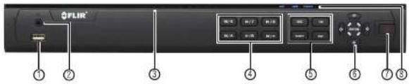
text_image
FLIR® ① ⑦ ③ ④ ⑤ ⑥ ⑦ ⑧- USB Port: Connect a USB mouse (included) or connect a USB flash drive (not included) for data backup or firmware upgrades.
- IR: Not supported.
-
Channel Indicators: Glow when camera is connected to the corresponding channel.
-
Playback Controls:
-
Pause/Play: In live view, press to enter playback mode. Press to play/pause playback.
• Reverse: Press to reverse playback/pause playback.
• Fast: Press to increase playback speed.
• Next: Press to skip to next video.
• Previous: Press to skip to previous video. - Slow: Press for slow playback.
5. Function Buttons:
• REC: Press to open manual recording controls.
• FN: Performs special functions in some menus.
- SHIFT: During text input press to switch input types
Rear Panel (DNR400 Series)

text_image
Labeled diagram of a network equipment rack showing ports, connectors, and ports with numbered annotations- Power input: Connect the included AC power cable.
- On / Off switch: Turns the NVR on or off.
- PoE Ports: Connect IP cameras. Integrated PoE (Power Over Ethernet) ports provide power to cameras and video connection to NVR
- LAN: Connect a CAT 5 RJ45 Ethernet cable for local and remote connectivity.
- VGA: Connect a VGA monitor (not included) to view the system interface.
- MIC IN/OUT: RCA input and output for 2-way audio.
Note
Audio-enabled IP cameras (not included) are required to use audio recording. You cannot record audio from the input (e.g. microphone) connected to the MIC IN port.
- HDMI: Connect to an HDMI monitor or TV (not included) to view the system interface.
- RS232: Service only; not supported.
- USB port(s): Connect a USB mouse (included) or USB thumb drive (not included) for data backup or firmware updates.
- Alarm block: Connect alarm/sensor devices (not included).
Basic Setup (DNR400 Series)
6.1 Step 1: Connect the IP Cameras
Option 1: Direct Connection to NVR
- Connect cameras to the PoE Ports on the rear panel of the NVR using Cat5e or higher grade Ethernet cable. The cameras will appear on the NVR without any additional configuration when the system starts up.
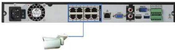
natural_image
Front view of a network equipment rack with ports, connectors, and ventilation unit (no visible text or labels)Connect IP cameras directly to PoE ports.
Option 2: Connect Cameras to Local Network
You can also connect your IP cameras to your local network for flexible installations. For details, see 6.11 Connecting Cameras to the Local Area Network (LAN), page 12.
6.2 Step 2: Connect the Mouse
- Connect a USB mouse (included) to one of the USB ports.
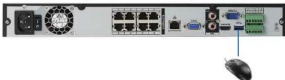
natural_image
Front view of a network equipment rack with ports, switches, and a mouse (no visible text or labels)- Connect a VGA cable (not included) from the VGA port to the monitor.
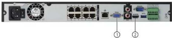
text_image
Internal view of a network equipment rack with labeled ports and connectors, showing power supply, fan, and terminal blocks.-
VGA port.
-
HDMI port
6.5 Step 5: Connect the Power Cable to Power the NVR
- Connect the included AC power cable to the NVR and connect the other end to a power outlet or surge protector. Then turn the power switch to I to power on the NVR.

natural_image
Back panel of a network equipment rack with ports, switches, and connectors (no visible text or labels)At startup, the system performs a basic system check and runs an initial loading sequence. After a few moments, the system loads a live display view.
6.6 Step 6: Upgrade Firmware to Latest Version (if Available)
If a firmware upgrade is available, you will be asked to install it once the system starts up. It is required to upgrade your system firmware and client software or mobile apps to the latest version to enable remote connection to the system.
6.8 Step 8: Set the Time
- Set the system time and date for accurate video time stamps. Videos with inaccurate times may not be valid as surveillance evidence.
- For details on setting the system time, see 10 Setting The Time, page 24.
6.9 Default System Password & Port Numbers

CAUTION
By default, the system user name is admin and the password is 000000. It is essential that you create your own password. For details, see 14 Managing Passwords and User Accounts, page 38.
The system requires a user name and password to log in to the system remotely using a computer or mobile device. After logging on remotely the first time, you will be asked to create a custom password for the system.
Local system and remote connectivity (LAN & Internet) user name and password:
- Username: admin
- Password: 000000
Default ports for DDNS remote access:
- Port 80 (HTTP port)
• Port 35000 (Client port)
6.9.1 FLIR Cloud™
This system features the exclusive FLIR Cloud™. This is a cloud service that allows you to connect to your system over the Internet via a secure handshake with our servers. This means you can easily connect to your system without requiring any network configuration.
For details on setting up your system to connect to the Internet using FLIR Cloud™:
• See 16 Connecting to Your System Over the Internet on PC or Mac, page 77. OR
Basic Setup (DNR400 Series)
text_image
Balance 0 Model Name: L200001 Performance: 9.5% Size: 16x100 F1/2000 F2/2000 S/C: 3.5x100 D: 1.5x100 M: 1.5x100 M/S: 1.5x100 M/S: 1.5x100 M/S: 1.5x100 M/S: 1.5x100 M/S: 1.5x100 M/S: 1.5x100 M/S: 1.5x100 M/S: 1.5x100 M/S: 1. OKNote
The QR code shown in the System Info screen can be scanned during mobile setup to enter the system's Device ID.
6.11 Connecting Cameras to the Local Area Network (LAN)
For flexibility, you may also connect IP cameras to the same Local Area Network (LAN) as the NVR. This is accomplished by connecting the cameras to the same router as the NVR. For these installations, an external PoE switch (sold separately) or power adapter (sold separately) must be used to provide power to each IP camera. You also must add the cameras on the NVR before they will show a picture on the monitor or be recorded by the NV Follow the steps below to connect the cameras to the NVR over the LAN.
Note
• For a list of 3rd party IP cameras supported, please visit www.flirsecurity.com/pro.
- Camera and NVR images in this section are used for illustration only.
Step 1 of 2 — Option A: Connecting cameras to your local network using a PoE switch:
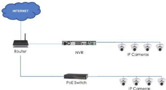
flowchart
graph TD
    A["INTERNET"] --> B["Router"]
    B --> C["NVR"]
    C --> D["IP Cameras"]
    B --> E["PoE Switch"]
    E --> F["IP Cameras"]
Step 1 of 2 — Option B: Connecting cameras to your local network using power adapters:

flowchart
graph TD
    A["INTERNET"] --> B["Router"]
    B --> C["NVR"]
    C --> D["IP Cameras"]
    C --> E["Power adapter (not included)"]
    B --> F["IP Cameras"]
    F --> G["Power adapter"]
-
Connect each camera to a compatible power adapter (visit www.flirsecurity.com/pro for compatible power adapters for your cameras).
-
Connect the camera to your router using a CAT5e or higher Ethernet cable.
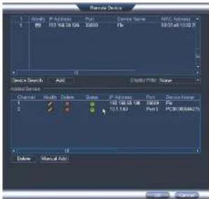
Step 2 of 2: Add the cameras to your NVR:
-
Right-click and select Device Search
-
Log in using the admin account (default User Name: admin; default Password: 000000).
-
Click Device Search. The system searches the network for compatible cameras.
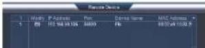
- Click Add. The Status indicator turns green to show the camera is successfully connected.
text_image
Remote Device 1 2 3 Device Search Add Add Device Color Width Color Size Port Address Port Device Name Port Port Port Port Port Port Port Port Port Port Port Port Port Port Port Port Port Port Port Port Port Port Port Port Port Port Port Port Port Port Port Port Port Port Port Port Port Port Port Port Port Port Port Port Port Port Port Port Port Port PCB0000000000000000000000000000000000000000000000000000000000000000000000000000000000000000000000000000Note
If the Status Indicator is red, click and update the info for your IP camera. Click OK to save changes.
- Click OK to save changes.
Note
You can also add a camera to a specific channel by hovering the mouse over an empty channel in split-screen view and clicking. Then double-click the camera you would like to add and right click to exit.
Mouse Control
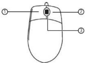
The mouse is the primary control device for the system. To connect a USB mouse:
- Connect a USB mouse to the USB port on the front or rear panel.
text_image
Diagram of a computer mouse with labeled parts: head, body, and interior-
Left-button:
-
In live view, click to open the Navigation Bar. Right-click to close the navigation bar.
- In live view, while in a split-screen display mode, double-click an individual channel
to view it in full-screen. Double-click again to return to the split-screen display mode. -
While navigating menus, click to open a menu option.
-
Right-button:
-
During live view, right-click anywhere on the screen to open the Quick Menu.
-
Within system menus, right-click to exit menus.
-
Scroll wheel: In live view, use the scroll wheel to zoom in/out.
Remote Control
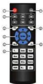
- Power: Press and hold to power off the system. Press to power on.
-
Playback controls:
-
Pause/Play: In live view, press to enter playback mode. Press to play/pause playback.
• Reverse: Press to reverse playback/pause playback.
• Fast: Press to increase playback speed.
• Next: Press to skip to next video.
• Previous: Press to skip to previous video. -
Slow: Press for slow playback.
-
Esc: In menus, press to go back / exit menus. In playback, press to return to live view.
8.1 Setting the Remote Control Address
If you have more than one system, you can set up your remote control to pair with a specific system.
To set the remote control address:
-
Right-click and click Main Menu. Enter the system user name (default: admin) and password (default: 000000).
-
Click >General>General.
-
Under Device No., enter the address number you would like to assign to the remote control.

text_image
DELETE Delete Type: 1234000 Delete As: 0 Language: Black View Selected: All Add Input: Options Post Options: 0 Interpretation: 0 Cartooning: 0 Supervision for CS Series Wizard User Open: 0 OK Cancel Help-
Click OK.
-
Using the remote control, press Add. Then enter the address number and press Enter.
Using the System
Use the system's graphical on-screen display to navigate menus and configure options and settings.
Note
Up to four channels at a time may be viewed using the system's high definition Main Stream. If more than four channels need to be viewed, additional channels will be displayed using the lower resolution Sub Stream. Although the live display picture will not be as sharp on these channels, all channels will still be recorded in high definition by default.
9.1 On-Screen Display
The system shows the following for all display views:

text_image
03.26-2014 DE SE 20PM CAM 1 C M 1 CAM 2 C M 2 CAM 3 C M 3 CAM 4 C M 4 CAM 5 C M 5 CAM 6 C M 69.2 Using the Quick Menu
The Quick menu gives you access to the system's key functions. To access the Quick Menu, right-click the screen during live view.
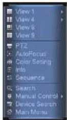
The Quick Menu has the following options:
- View: Select a camera in full-screen or select a multi-channel display.
- Pan/Tilt/Zoom: Access controls for PTZ cameras (not included).
- AutoFocus: Access zoom/focus controls for auto-focus cameras (not included).
• Color Setting: Configure image settings for cameras. - Info: Opens the system information window.
- Sequence: Click to start/stop sequence mode.
In sequence mode, the system will automatically cycle through connected cameras
every few seconds. 📄 will appear to show that sequence mode is on.
Click the icon to pause sequence mode on the channel that is currently shown (icon changes to 📄). Click again to resume sequence mode.
Right-click and select Sequence to return to normal viewing mode.
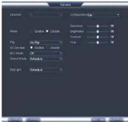
- Configure the following settings as needed:
text_image
Create Locking Name: Grade Size: Size Size Size Size Size Size Size Size Size Size Size Size Size Size Size Size Size Size Size Size Size Size Size Size Size Size Size Size Size Size Size Size Size Size Size Size Size Size Size Size Size Size Size Size Size Size Size Size Size Size SizeNote
The settings listed below are only shown if they are supported on the selected camera. Some camera models do not support all settings.
- Mirror: Select Enable to flip the image horizontally.
- Flip: Select Flip 180° to flip the image vertically, or select No Flip for the default orientation.
- 3D Denoise: Select Enable to turn on the camera's noise reduction feature. Noise reduction will ensure a cleaner image, especially at night, and may reduce the amount of disk space required to store video.
- BLC Mode: Select High or Low to enable back light compensation or Off to disable. Back light compensation adjusts the lighting levels in the picture so you can see objects in the foreground if there is a strong light source behind them.
- Scene Mode: The Scene Mode allows you to adjust white balance levels for the camera. Select Schedule for the camera to automatically adjust the white balance. Select Sunny or Night to use preset white balance levels. Select Customized to manually set blue and red levels.
9.4 Using the Navigation Bar
The Navigation Bar gives quick access to certain functions and menus.
To open the Navigation bar:
- Left click on the screen to open the Navigation Bar. The Navigation Bar has the following options:
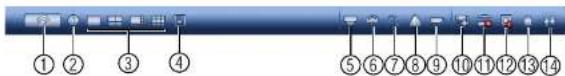
text_image
Screenshot of a software toolbar with numbered icons for function keys or system functions-
Main Menu.
-
Collapse.
-
Select display layout.
-
Sequence: Click to start/stop sequence mode.
-
PTZ: Click to open PTZ controls.
-
Camera: Click to open camera image settings.
-
Search: Search and playback recorded video. See 17.4 Playback, page 89.
-
Alarm Status: View alarms in progress. See 15.2.4 Event Info, page 49.
-
Channel Info: Click to access status information about connected cameras.
-
Device Search: Manage IP cameras over the network
-
Network: Configure network settings for your system. See 15.3.1 Network, page 53.
-
HDD Manager: Manage hard drives connected to the system. See 15.3.19 Formatting the Hard Drive, page 67.
-
USB Manager: Click to access options for connected USB thumb drives (not included). You can
backup video, logs, or system configurations and install firmware upgrades.
- System Upgrade: Check for firmware upgrades. The system must be connected to the Internet to
check for or receive updates.
9.5 Using the Camera Toolbar
The Camera Toolbar is used to perform actions on a specific channel.
To access the Camera Toolbar:
To use Quick Playback:
- Move your mouse to the top of the channel display and click
Note
By default, the system will begin playback from 5 minutes ago. You can increase this to up to 60 minutes using the Instant Playback setting in Main Menu>Setting>General.
- Right-click to exit Quick Playback.
9.5.2 Using Digital Zoom in Live Display
- Move your mouse to the top of the channel display and click to activate digital zoom. A check mark will appear in the icon to indicate digital zoom is activated.
Note
You may activate digital zoom in multiple channels at the same time.
- Click and drag inside the channel to zoom in.
- Click and drag to pan the zoom area.
- Right-click to zoom out and select a new zoom area.
- Click 📷 to disable digital zoom. Note that the channel will remain at the same zoom level until you right-click inside it.
9.5.3 Using Real-time Backup
Real-time backup allows you to save footage from the live display to a USB thumb drive (not included) or external hard drive (not included).
To use Real-time Backup:
- Insert the USB thumb drive or external hard drive into one of the USB ports on the system.
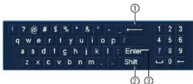
text_image
1 ? @ # $ % * & ' . q w e r t y u i o p / 1 2 3 a s d l g h j k l : Enter 4 5 6 z x c v b n m . Shift 7 8 9 ① ← 0 ←- Backspace.
- Enter capital letters.
- Confirm entry
9.7 Adjusting Camera Zoom & Focus
Auto-focus cameras (not included) have a motorized lens. The motorized lens allows you to control the zoom and focus settings using the menus on your system.

text_image
Zoom 0 Focus 11 AutoFocus Default RefreshTo adjust the camera's zoom focus:
- Double-click on the channel where the motorized lens camera is connected.
- Right-click and then click AutoFocus. Log into the system using the admin account (default user name is admin and password is 000000).
- Adjust the zoom and focus using the following options:
- Use the sliders to adjust the Zoom or Focus settings for the camera
Setting The Time

CAUTION
It is highly recommended to set the date and time when first setting up your system. Inaccurate time stamps may render your footage unusable for court evidence.
To set the date and time:
- In the main viewing mode, right-click and click Main Menu.
-
Log in using the system user name (default: admin) and password (default: 000000).
-
Click

and select Setting. Click General and select the Date&Time tab.
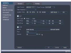
text_image
DATA DISPLAY WRITE RICH TATTOCOM ACCOUNT Config/backup OFFSET UPDATE Close Set/Find Help Data Format SAB 00:1974 - Time Series: SAB/CUR Data Seguros: System Type: 86.30 X76.16 16 32.88 MB GAP:45.65 OK GPT Type Reset Time Max = 0.14 Min = 0.14 Max = 0.14 Min = 0.14 Max = 0.14 Max = 0.14 Max = 0.14 Max = 0.14 Max = 0.14 Max = 0.14 Max = 0.14 Max = 0.14 Max = 0.14 Max = 0.14 Max = 0.14 Max = 0.14 Max = 0,14 Max = 0,14 Max = 0,14 Max = 0,14 Max = 0,14 Max = 0,14 Max = 0,14 Max = 0,14 Max = 0,14 Max = 0,14 Max = 0,14 Max = 0,14 Max = 0,14 Default OK Cancel Apply- Under System Time, enter the current time and select your time zone. Then, click OK.
- Check DST to enable auto Daylight Savings Time updates.
Note
- You can adjust the Start Time and End Time for Daylights Savings Time if the default settings do not match your region.
• Under DST Type, select Day of Week to set the start and end time based on a day and week (e.g. 2nd Sunday in March), or select Date to set the start and end time to a specific date
Recording
By default, the system is set to immediately record video from connected cameras continuously, 24 hours a day. You can customize the recording settings according to your needs.
11.1 Video Recording Types
The system supports the following recording types.
- Recording—Continuous: Normal, continuous recording. A C icon is shown when recording is in progress.
- Recording—Motion: The system records when motion is detected by the camera. An icon is shown when motion is detected.
11.2 Main Stream and Sub Stream
The system employs two video recording streams, a Main Stream and a Sub Stream. Both Main Stream and Sub Stream recording are enabled by default.
The Main Stream records high quality video to your system's hard drive.
The Sub Stream records lower resolution video for efficient streaming to devices over the Internet. Sub Stream recording must be enabled to view video recordings on a computer or mobile device.
You can configure the video quality parameters for the Main Stream or Sub Stream. For details, see 15.1.6 Configuring Recording Quality, page 44.
11.3 Setting up Scheduled or Manual Recording
You can set the system to record based on a schedule or you can manually turn recording on and off. By default, the system is set to record on an always on recording schedule.
To configure the recording schedule, see 15.3.15 Configuring the Video Recording Schedule, page 64.
To select between scheduled and manual recording:
- Right-click and then select Manual>Record.
Recording11
-
Under Main Stream, select how the system will record the Main Stream for each channel.
-
Schedule: Main Stream Recording will follow the recording schedule.
- Manual: The system will record the Main Stream continuously as long as this option is checked.
-
Stop: The system will not record the Main Stream for this channel. This option is not recommended.
-
Under Sub Stream, select how the system will record the Sub Stream for each channel.
-
Schedule: Sub Stream Recording will follow the recording schedule.
- Manual: The system will record the Sub Stream continuously as long as this option is checked.
-
Stop: The system will not record the Sub Stream for this channel.
-
Under Snapshot, select Enable to enable snapshot recording on each channel. Or, select Disable to disable snapshot recording.
- Click OK to save changes.
11.4 Configuring Hard Drive Overwrite
When the hard drive is full, the system will overwrite the oldest recordings by default. This is recommended, as it makes sure that your system will continue to record without any input from you. You can also set the system to stop recording once the hard drive is full.
To configure hard drive overwrite:
-
Right-click and select Main Menu. Click ✗ > Setting>General>General.
-
Under HDD Full, select Overwrite for the system to overwrite the oldest recordings when the hard drive is full. Or, select Stop Record for the system to stop recording when the hard drive is full.

Search (Playback)
Search mode is used to navigate and playback recorded video files on the system.
12.1 Playing Back Video from the Hard Drive
- From live view, right-click and then click Search.
- Log in using the system user name (default: admin) and password (default: 000000).
- Configure the following:

text_image
Screenshot of a video editing software interface with labeled UI elements and tool panels3.1. Use the calendar on the right to select the day to playback.
3.2. Use the drop-down menus to select the channels you would like to playback.

3.3. Click Inside the video bar to select the playback time. The system will begin
12.2 Playback Controls
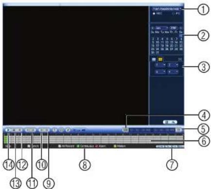
text_image
Screenshot of a video editing software interface with numbered labels pointing to various media clips and tracks.-
Select playback device.
-
Calendar: Select the day to playback.
-
Channel select: Select channels to playback.
-
Video clip backup: Select video clip start and end times.
-
Backup video clip: Click to save selected clip.
-
Playback Bar: Click inside the bar to select a playback time.
-
Zoom Playback Bar: Select scope of time bar.
-
Recording types: Click to showwhile recording types.
-
Speed up.
-
Slow.
-
Click From ReadWrite Hdd and select From IO Device. Click Browse to open the USB drive and manually select the video file.

text_image
Add As Add As Delete Save As End As Save As- Double click the video file you would like to open.
Backup
Backup video files to external USB flash drive (not included) or self-powered USB external hard drive (not included).
Note
USB external hard drives must be formatted in the FAT32 file format to be used with the system.
13.1 Formatting the USB Thumb Drive
It is recommended to format your USB thumb drive (not included) before using it with the system.

CAUTION
Formatting the USB device will permanently erase all data.
To format a USB device:
- Insert a USB thumb drive (not included) into one of the USB ports.
-
From live view, right-click and then select Main Menu. Login if prompted.
-
Click >Backup.
-
Select the USB device you would like to format under Device Name and click Browse.
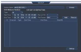
text_image
File Path: x8-06.000 (GB) 0.05 GB/1.23 GB(FireTotal) Type: 24 Start Time: 04 - 15 - 2016 12 30 63.667 PassesOut End Time: 04 - 15 - 2016 11 25 43.667 File Paths (MBV) Forward Type: Start Time End Time Stop(Off) Add New Exit(Off)Backup13
13.2 Backing up Video
- Insert a USB thumb drive (not included) into one of the USB ports.
-
From live view, right-click and then select Main Menu. Login if prompted.
-
Click >Backup.
-
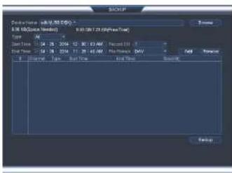
Configure your search options:
text_image
File Name: 01-02 (RGB) F:\3.0\B\Box\Box\Box\Box\Box Type: All Start Time: 04:15 - 2016 - 12 - 30.13 AM Report: 0 End Time: 04:18 - 2016 - 11 - 25.41 AM Print: None MV [ ] [ ] [ ] [ ] [ ] [ ] [ ] [ ] [ ] [ ] [ ] [ ] [ ] [ ] [ ] [ ] [ ] [ ] [ ] [ ] [ ] [ ] [ ] [ ] [ ] [ ] [ ] [ ] [ ] [ ] [ ] [ ] [ ] [ ] [ ] [ ] [ ] [ ] [ ] [ ] [ ] [ ] [ ] [ ] [ ] [ ] [ ] [ ] [ ] [ ] [ ]- Select the USB device you would like to format under Device Name.
• Type: Select the recording type you would like to search for or select All to search
all recording types. - Channel: Select the channel you would like to search or select All to search all channels.
- File Format: Select DAV to save files to save files to .dav format. You can playback .dav files using the FLIR video player software from www.flirsecurity.com/pro. Or, select ASF for .asf format. You can playback .asf files in VLC Media Player (free download from www.videolan.org) on PC or Mac.
Note
Backup13
- Start playing back video using the steps in 12.1 Playing Back Video from the Hard Drive, page 27.
- Click to mark the beginning of the video clip. Click again to mark the end of the video clip.
- Click to open the Backup menu.
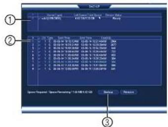
- Configure the following:
text_image
① ② ③ Speed Request: "Speed Prompting" (100 MHz) (20 Hz) OK Cancel Next Step 1. 00:04:17 16:30 AM 2. 00:15:18 16:30 PM 3. 00:16:19 16:30 PM 4. 00:17:20 16:30 PM 5. 00:18:21 16:30 PM 6. 00:19:22 16:30 PM 7. 00:20:23 16:30 PM 8. 00:21:24 16:30 PM 9. 00:22:25 16:30 PM 10. 00:23:26 16:30 PM 11. 00:24:27 16:30 PM 12. 00:25:28 16:30 PM 13. 00:26:29 16:30 PM 14. 00:27:30 16:30 PM 15. 00:28:31 16:30 PM 16. 00:29:32 16:30 PM 17. 00:30:33 16:30 PM 18. 00:31:34 16:30 PM 19. 00:32:35 16:30 PM 20. 00:33:36 16:30 PM Speed Request: "Speed Prompting" (100 MHz) (20 Hz)5.1. Check the USB device where you would like to save the file.
5.2. Check the files you would like to backup.
5.3. Click Backup. Then click Start. Wait for the backup to complete before removing the USB thumb drive.
13.4 Viewing Backup Files
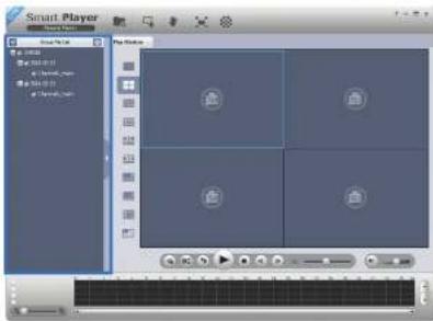
To playback .dav backup video files, a Player is available for PC and Mac at www.flirsecurity.com/pro.
Backup13
- Double click one of the files on the left to begin playback.
text_image
Smart Player Game Tools Help Play Studio 1 2 3 4 5 6 7 8 9 10 11 12 13 14 15 16 17 18 19 20 21 22 23 24 25 26 27 28 29 30 31 32 33 34 35 36 37 38 39 40 41 42 43 44 45 46 47 48 49 50 51 52 53 54 55 56 57 58 59 60 61 62 63 64 65 66 67 68 69 70 71 72 73 74 75 76 77 78 79 80 81 82 83 84 85 86 87 88 89 90 91 92 93 94 95 96 97 98 99 100OR
Click to open a back up video file in another location.
- Use the Player controls to control playback or select other files for playback.
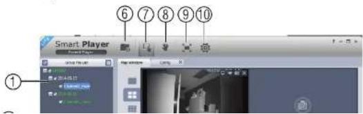
Video Player Controls
text_image
Smart Player 1 - 5 x ① ⑥ ⑦ ⑧ ⑨ ⑩Backup13
- Display Area: Select the split-screen mode. Double-click a video file to expand. Click the controls inside the display area to do the following:
• View information about the video file.
• Start/stop a manual recording from the video file.
• Take a snapshot from the video file.
- ✗: Close the video file.
-
Hide/show file list.
-
Playback controls:
• Playback files in sequence.
• Synchronize playback times.
• Play/pause playback.
• : Stop playback.
•: Previous frame.
• Next frame.
• IX : Playback speed.
• : Volume control.
-
Zoom Timeline.
-
Add Files: Click to open back up video files.
-
Digital Zoom: Click to activate digital zoom mode. Click and drag in the video to zoom
Backup13
- Config: Click to open the configuration menu for the player. From here you can control the default file formats and save locations for snapshots and video files saved from the player.
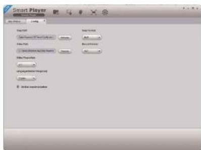
text_image
Smart Player File Name: C:\Users\My Documents\My Path File Type: Normal File Source: Normal File Properties: Normal Language: Normal Name: Normal Edit Subscribers13.4.2 Viewing Backup Files on Mac
A Video Player for Mac is available from www.flirsecurity.com/pro.
To view backup video files using the Player on Mac:
-
Download Video Player for Mac from www.flirsecurity.com/pro.
-
Double click the downloaded file in Safari to extract the Smart Player app file.

Backup13
- Double click one of the files on the left to begin playback.

text_image
Player View Player Play Window Daily 12:30:51 19:45:50 E-01OR
Click to open a back up video file in another location.
- Use the Player controls to control playback or select other files for playback.
Video Player Controls
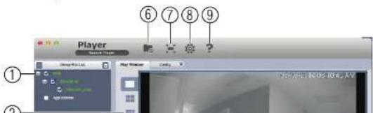
text_image
Player ① ② ⑥ ⑦ ⑧ ⑨ Play Window Control Play Tools Help Play Options HelpBackup13
- Display Area: Select the split-screen mode. Double-click a video file to expand. Click the controls inside the display area to do the following:
• View information about the video file.
• Take a snapshot from the video file.
- ✗: Close the video file.
-
Hide/show file list.
-
Playback controls:
-
When a video file ends, this button lets you select if you want the video player to repeat the same file or play the next file.
• : Play/pause playback. -
: Stop playback.
•: Previous file.
• Next file.
• IX —— : Playback speed.
• : Volume control. -
Zoom Timeline.
-
Add Files: Click to open back up video files.
-
Full-screen: Click to open the player in full screen. Press ESC to exit full screen.
-
Config: Click to open the configuration menu for the player. From here you can control the default file formats and save locations for snapshots and control the aspect ratio.
Managing Passwords and User Accounts
By default, the system user name is admin and the password is 000000. Passwords are enabled by default and are required to access the Main Menu or connect to the system using a computer or mobile device. You will be prompted to create a custom password after you connect for the first time.
Note
If you forget the password to the system, contact technical support to have it reset.
The system includes the following default accounts:
- admin: The admin account has full access to the system, may configure all system settings, and can manage user accounts.
- default: The default account is a limited user account that may only view live video from the cameras.
For security reasons, it is essential that you change the password on your system. By default, the system password is enabled.
14.1 Changing Passwords
You can change the system password of the admin and user accounts from the Users menu.
To modify an account password:
- From Live View, right-click and then select Main Menu.
- If prompted, enter the system user name (default: admin) and password (default: 000000).

-
Click X and select Setting. Select Account.
-
Click next to the user account you would like to modify.

Managing Passwords and User Accounts14
To add a user account:
-
From Live View, right-click and then select Main Menu.
-
If prompted, enter the system user name (default: admin) and password (default:
000000)
-
Click and select Setting. Select Account.
-
Click Add User.
-
Configure the following:
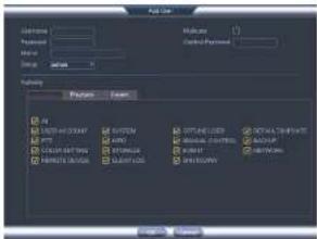
text_image
File Edit Name: Properties: Edit Delete Help Preview Form1 SPTT-030047 PPT COMPARTING RANGE FLOOR SYSTEM MOSSEM MOSSEM MOSSEM MOSSEM DETAIL-COMPLANT MASCUM MASCUM MASCUM MASCUM- User Name: Enter a name for the user account.
- Password: Enter a 6 character password for the user account. Enter the password again under Confirm Password.
- Memo (optional): Enter a description of the user account.
- Group: Select the group you would like to assign to this user account. A user ac-
count cannot be given permissions its group does not have.
- Multiuser: Check to enable this user account to be used to login from more than one device at the same time.
- Authority: Check the permissions you would like the user account to have. Under the System tab, select the menus the user account may access. Under the Play-back tab, select which channels the user account may access recorded video from.
Managing Passwords and User Accounts14
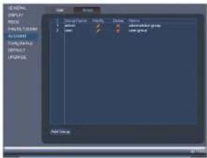
14.5 Account Groups
Account groups can be used to easily manage permissions for multiple user accounts. User accounts can be given all the permissions of a group, but cannot be given permissions that the group does not have.
The system includes the following groups by default:
- admin: Accounts in the admin group are system administrators. They have full access to the system, may configure all system settings, and can manage user accounts.
- user: Accounts in the user group are normal users. They have limited access to system menus.
14.6 Adding Groups
- From Live View, right-click and then select Main Menu.
-
If prompted, enter the system user name (default: admin) and password (default: 000000).
-
Click ✗ and select Setting.
-
Click Account and select the Group tab.
-
Click Add Group.
text_image
NEW DISPLAY HKEY WIN/SPX ACCOUNT TCP/IPK DATA POPID Add Menu14.7 Modifying Groups
- In the Group tab, click next to the group you would like to modify.
- Update the group's details as needed, and then click OK to save changes.
14.8 Deleting Groups
- In the Account menu, click next to the user account you would like to delete.
- Click OK to confirm.
Note
The admin and user groups cannot be deleted from the system.
Using the Main Menu
To open the Main Menu:
- Using the mouse: Right-click and click Main Menu.
Note The system password is required to access the Main Menu. By default the user name is admin and the password is 000000.
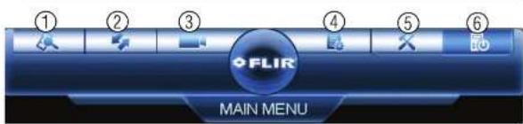
text_image
FLIR MAIN MENU- SEARCH: Open Search/Playback mode. For details, see 12 Search (Playback), page 27.
- BACKUP: Export files to USB device. For details, see 13 Backup, page 30.
- CAMERA: Open the menu to manage IP cameras connected to the network (see 6.11 Connecting Cameras to the Local Area Network (LAN) for details), set recording parameters, and assign custom titles for your cameras.
- INFO: View system information.
- SETTING: Configure general system, schedule, network, recording, display, and motion settings. Restore system to factory defaults.
- SHUTDOWN: Logout, restart, or shutdown the system.
15.1 Camera
Open the Remote Device menu to manage IP cameras, set recording parameters, and assign custom titles for your cameras.

Using the Main Menu15
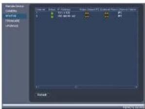
15.1.2 Viewing Camera Status
The Camera Status menu allows you to view the connection and alarm status for all connected cameras.
To view camera status:
- From the Main Menu, click and select Remote Device>Status.
text_image
Name: D:\Users\Program Files\Control Panel\Program Files\Status\Status\Status\Status\Status\Status\Status\Status\Status\Status\Status\Status\Status\Status\Status\Status\Status\Status\Status\Status\Status\Status\Status\Status\Status\Status\Status\Status\Status\Status\Status\Status\Status\Status\Status\Status\Status\Status\Status\Status\Status\Status\Status\Status\Status\Status\Status\Status\Status\Status\(^{1}\) Status: D:\Users\Program Files\Control Panel\Program Files\Status\Status\Status\Status\Status\Status\Status\Status\Status\Status\Status\Status\Status\Status\Status\Status\Status\Status\Status\Status\Status\Status\Status\Status\Status\Status\(^{2}\) Status: D:\Users\Program Files\Control Panel\Program Files\Status\Status\Status\Status\Status\Status\Status\Status\Status\Status\Status\Status\Status\Status\Status\Status\Status\Status\Status\Status\Status\Status\Status\(^{3}\) Status: D:\Users\Program Files\Control Panel\Program Files\Status\Status\Status\Status\Status\Status\Status\Status\Status\Status\Status\Status\Status\Status\Status\Status\Status\Status\Status\(^{4}\) Status: D:\Users\Program Files\Control Panel\Program Files\Status\Status\Status\Status\Status\Status\Status\Status\Status\Status\Status\Status\Status\Status\nBalance:15.1.3 Viewing Camera Firmware Versions
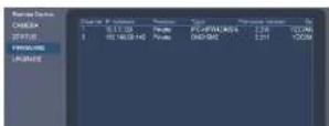
You can use the Firmware menu to view firmware versions for connected cameras.
To view camera firmware versions:
- From the Main Menu, click and select Remote Device>Firmware.
Using the Main Menu15
-
Extract the firmware file and copy it to a USB thumb drive (not included).
-
Insert the USB thumb drive (not included) into a USB port on the system.
-
Right-click and select Main Menu. Click ____ and select Remote Device>Upgrade.
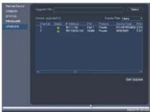
text_image
Display Pro File Edit View Help 1 2 3 4 5 6 7 8 9 10 11 12 13 14 15 16 17 18 19 20 21 22 23 24 25 26 27 28 29 30 31 32 33 34 35 36 37 38 39 40 41 42 43 44 45 46 47 48 49 50 51 52 53 54 55 56 57 58 59 60 61 62 63 64 65 66 67 68 69 70 71 72 73 74 75 76 77 78 79 80 81 82 83 84 85 86 87 88 89 90 91 92 93 94 95 96 97 98 99 100-
Click Select. Select the firmware file on the USB drive and click OK.
-
Check the cameras you would like to apply the upgrade to in the list and then click Start Upgrade.
CAUTION Wait for the firmware upgrade to complete before turning off or unplugging the cameras or NVR. The cameras will restart during the firmware update process.
15.1.5 Recording
The Recording menu allows you to set recording parameters for your cameras, such as the resolution and frame rate.
15.1.6 Configuring Recording Quality
Using the Main Menu15
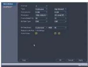
- Configure the following settings. Settings for the Main Stream are in the left column. Settings for the Sub Stream are in the right column.
text_image
INCHINESE IMPORT Name: 12 Size: 500 Size: 500 Size: 100 Size: 100 Size: 100 Size: 100 Size: 100 Size: 100 Size: 100 Size: 100 Size: 100 Size: 100 Size: 100 Size: 100 Size: 100 Size: 100 Size: 10 Size: 10 Size: 10 Size: 10 Size: 10 Size: 10 Size: 10 Size: 10 Size: 10 Size: 10 Size: 10 Size: 10 Size: 10 Size: 10 Size: 10 Size: 10 Size: 10 Size: Size: Size: Size: Size: Size: Size: Size: Size: Size: Size: Size: Size: Size: Size: Size: Size: Size: Size: Size: Size: Size: Size: Size: Size: Size: Size: Size: Size: Size: Size: Size: Size: Size: Size: Size: Size: Size: Size: Size: Size: Size: Size: Size: Size: Size: Size: Size: Size: Size: Size:- Resolution: Select the resolution that you want to use to record the selected channel. Higher resolutions create a more detailed image, but take up more hard drive space to record and require more bandwidth to stream to connected computers or mobile devices.
Note
Available resolutions for the Main Stream and Sub Stream depend on the model of camera that is connected to the system.
- Compression: Select the video compression type that will be used. It is recommended to select H.264, as it will have the best performance and use the least amount of disk space.
- Frame Rate (FPS): Select the frame rate in Frames Per Second (FPS) that each stream will record at. A higher frame rate provides a smoother picture, but requires more storage and bandwidth.
- Bit Rate Type: Select CBR (Constant Bit Rate) or VBR (Variable Bit Rate) to determine the bit rate type. If you select VBR, you can set the video quality setting between 1 and 6. If you select VBR, select the Quality from 1 (lowest) to 6 (highest).
Using the Main Menu15
To configure audio recording:
- From the Main Menu, click and select Recording>Recording.

text_image
LOGICAL MARKET Type: 3 Color: 0.000 Noise: 100% View Mode: 50 View Type: 100 View Mode: 100 View Mode: 100 Output: 100 OK Cancel Help- Select the audio-enabled camera under Channel.
- Check the left Audio/Video checkbox to enable audio recording. Check the middle checkbox to enable audio streaming to remote devices (such as a smartphone). Check the right checkbox to enable video streaming to remote devices.
- Click OK to save changes.
15.1.8 Configuring Snapshot Recording Settings
The system can be set to record snapshot images when a camera detects motion. These snapshots can be viewed through the Search menu or can be attached to email alerts and push notifications. The Snapshot tab in the Recording menu controls the quality and recording parameters for each camera.
Note
In order to enable Snapshot recording, the following menu options must be configured:
- The Snapshot schedule must be enabled for times that you would like to save snapshots. See 15.3.17 Configuring the Snapshot Schedule, page 65.
- Snapshot recording must be enabled for motion detection in the Event menu. See 15.3.8 Configuring
Using the Main Menu15
- Configure the following settings for snapshots saved automatically from motion detection or the snapshot schedule:

text_image
RESEARCH Tracking Design Options 100% Change 3 Match 50% Angle Top 45° Angle Angle 45° Drop and Passes 100% OK Cancel Apply- Channel: Select the channel you would like to configure.
- Mode: Select Timing for the system to take snapshots according to the snapshot schedule (see 15.3.17 Configuring the Snapshot Schedule, page 65) Select Trigger for the system to take snapshots only when triggered by motion detection (snapshot must be enabled in the Motion Detect menu; see 15.3.8 Configuring Motion Detection, page 57).
- Image Size: The image size is the same as the Main Stream resolution of the camera.
- Image Quality: Select the snapshot image quality between 1 (lowest) and 6 (highest).
-
Snapshot Frequency: Select the number of snapshots (up to 6) the system will take each time.
-
Click OK to save changes.
15.1.9 Creating Custom Channel Names
You can assign custom names to your cameras. For example, you can name your cameras based on their location (e.g. hallway or front door).
Using the Main Menu15
15.2 Info
Info contains menus that show you system information.
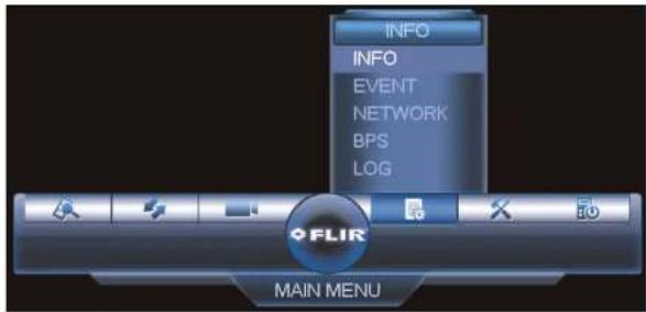
text_image
INFO INFO EVENT NETWORK BPS LOG FLIR MAIN MENU15.2.1 HDD Info
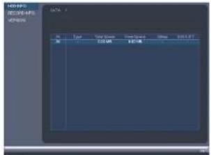
text_image
1200-8P0 1200-8P6 1200-8P4 DATA: 3 Type Size/Order Front Square Balance 100% 57 0.0 0.0 0.0 0.0 0.0 0.0 COS MR 925.0kUsing the Main Menu15
The Record Info menu shows the start and end times of recordings saved on the hard drive.
To access the Record Info menu:
- From the Main Menu, click E _0 and then select Info>Record Info.
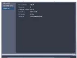
15.2.3 Version
text_image
Windows Microsoft Teams 开始菜单 Device selection 选项 Change 0 Performance: 100% Model Type: 200x200.00 Win/Winset 2.524 Save As IP-CLOSE/HOSSSThe Version sub-menu allows you to view information about the current firmware installed on the system.
To access the Version menu:
- From the Main Menu, click 📄 and then click Info>Version.
15.2.4 Event Info

Using the Main Menu15
- Camera Masking: Camera masking alarm has been triggered (e.g. someone has covered the camera lens).
- Motion Detect: Shows channels with active motion alarms.
- IPC Ext Alarm: Alarm/sensor device (not included) connected to camera has been triggered.
- IPC Offline Alarm: IP camera is offline.
To access the Event Info menu:
- From the Main Menu, click Event and then select Event.
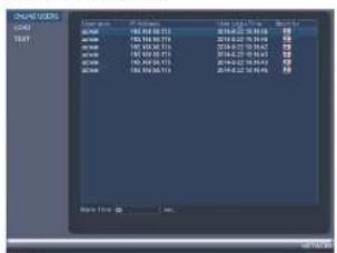
15.2.5 Online Users
text_image
ORANGE USERS LOGO 00164 780.00.00 03:52 00164 780.00.00 03:53 00164 780.00.00 03:54 00164 780.00.00 03:55 00164 780.00.00 03:56 00164 780.00.00 03:57 00164 780.00.00 03:58 00164 780.00.00 03:59 00164 780.00.00 03:60 00164 780.00.00 03:61 00164 780.00.00 03:62 00164 780.00.00 03:63 00164 780.00.00 03:64 00164 780.00.00 03:65 00164 780.00.00 03:66 00164 780.00.00 03:67 00164 780.00.00 03:68 00164 780.00.00 03:69 00164 780.00.00 03:70 00164 780.00.00 03:71 00164 780.00.00 03:72 00164 780.00.00 03:73 00164 780.00.00 03:74 00164 780.00.00 03:75 00164 780.00.00 03:76 Total Users: 2,259,259,259,259The Online Users menu shows a list of users connected to the system using computers or mobile devices.
To access Online Users:
- From the Main Menu, click 📄 and then select Network.
15.2.6 Load

Using the Main Menu15
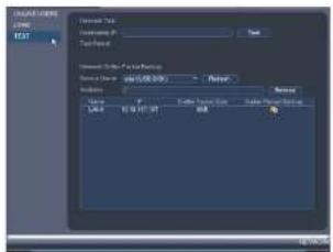
15.2.7 Test
text_image
Digital Text Long: POST Normal Text Custom Text Text Normal Text & Text Format Normal Text: size: 25.00 GB Width: 10.00 GB Name: Type: Date: Date: 07-07-07 Date: 07-07-07 Source: Source: AutoCAD Source: AutoCADThe Test menu allows you to test if your system can connect to other devices over the LA or Internet. You can enter the IP address of a device and click Test to determine if your system can connect to it.
To access Test:
- From the Main Menu, click and then select Network>Test.
15.2.8 BPS
The BPS sub-menu shows the bitrates of connected cameras. the bitrate is the amount of data the camera is sending to the system.

text_image
CNC M2 TWP M4 TWP M6 TWP M8 TWP M10 TWP M12 TWP M14 TWP M16 TWP M18 TWPUsing the Main Menu15
text_image
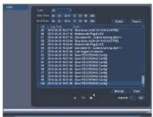
File Name: 01.04.2016 17:03:2016 17:03:2016 File Size: 01.04.2016 17:03:2016 17:03:2016 Status: Normal 1.04.2016 01.04.2016 2.04.2016 01.04.2016 3.04.2016 01.04.2016 4.04.2016 01.04.2016 5.04.2016 01.04.2016 6.04.2016 01.04.2016 7.04.2016 01.04.2016 8.04.2016 01.04.2016 9.04.2016 01.04.2016 10.04.2016 01.04.2016 11.04.2016 01.04.2016 12.04.2016 01.04.2016 13.04.2016 01.04.2016 14.04.2016 01.04.2016 15.04.2016 01.04.2016 16.04.2016 01.04.2016 17.04.2016 01.04.2016 18.04.2016 01.04.2016 19.04.2016 01.04.2016 20.04.2016 01.04.2016 21.04.2016 01.04.2016 22.04.2016 01.04.2016 23.04.2016 01.04.2016 24.04.2016 01.04.2016 25.04.2016 01.04.2016 26.04.2016 01.04.2016 27.04.2016 01.04.2016 28.04.2016 01.04.2016 29.04.2016 01.04.2016 30.04.2016 01.04.2016 31.04.2016 01.04.2016 32.04.2016 01.04.2016 33.04.2016 01.04.2016 34.04.2016 01.04.2016 35.04.2016 01.04.2016 36.04.2016 01.04.2016 37.04.2016 01.04.2016 38.04.2016 01.04.2016 39.04.2016 01.04.2016 40.04.2016 01.04.2016 41.04.2016 01.04.2016 42.04.2016 01.04.2016 43.04.2016 01.04.2016 44.04.2016 01.04.2016 45.04.2016 01.04.2016 46.04.2016 01.04.2016 47.04.2016 01.04.2016 48.04.2016 01.04, 5x5x5x5x5x5x5x5x5x5x5x5x5x5x5x5x5x5x5x5x5x5x5x5x5x5x5x5x5x5x5x5x5x5x5x5x5x5x5x5x5x5x5x5x5x5x5x5x5x5x5, 5x5x5x5x5x5x5x5x5x5x5x5x5x5x5x5x5x5x5x5x5x5x5x5x5x5x5x5x5x5x5x5x5x5, 5x5x5x5x5x5x5x5x5x5x5x5, 5x5x5x5x5, 5x5x5x5, 5x5x5, 5x5, 5, 5, 5, 5, 5, 5, 5, 5, 5, 5, 5, 5, 5, 5, 5, 5, 5, 5, 5, 5, 5, 5, 5, 5, 5, 5, 5, 5, 5, 5, 5, 5, 5, 3, 3, 3, 3, 3, 3, 3, 3, 3, 3, 3, 3, 3, 3, 3, 3, 3, 3, 3, 3, 3, 3, 3, 3, 3, 3, 3, 3, 3, 3, 3, 3, 3, 3To search for system logs:

- From the Main Menu, click and then select Log.
- Under Type, select the log type to search for.
- Under Start Time and End Time, select the start and end time for your search.
- Click Search.
- (Optional) Click Backup to export logs to a USB thumb drive connected to the system.
Using the Main Menu15
15.3 Setting
The Setting menu allows you to configure general system, schedule, network, recording, display, and motion settings. It also allows you to restore the system to factory defaults.

text_image
SETTING NETWORK EVENT STORAGE SETTING FLIR MAIN MENU15.3.1 Network
The Network menu allows you to configure network parameters for your system.
Note
The WiFi menu is not supported.
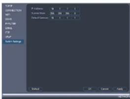
15.3.2 Selecting DHCP or Static IP Address (TCP/IP)
The TCP/IP menu allows you to configure IP address settings.
To configure IP address settings:
-
From the Main Menu, click X and then select Network>TCP/IP.
-
Check DHCP (recommended) to let the system automatically obtain an IP address from the router or uncheck to assign a static IP address.

text_image
TCP/IP CONNECTION FTP DOOR IP FILTER PANET FTP POP SNR: 58888 IP Address IP Address S-Code Width 100 100 100 100 Dialysis Connection 100 100 100 100 Pseudo ID 1 2 3 4 5 6 Ethernet ID 1 2 3 4 5 6 OK Cancel Apply DefaultIf you uncheck DHCP, configure the following:
- IP Address: Enter the IP address you would like to assign to the system. Make sure that no other device on your network is using the same IP address.
- Subnet Mask: Enter the subnet mask for your network.
- Default Gateway: Enter the gateway address for your network.
- Preferred DNS: Enter the address of your primary DNS server
-
Alternate DNS: Enter the address of your secondary DNS server.
-
Click OK to save changes.
15.3.3 Configuring System Ports (Connection)
The Connection menu allows you to configure ports used by the system. Please note that port forwarding is not required to use FLIR Cloud™ or to connect using the apps.
If you are using DDNS connectivity, port forwarding is required for the HTTP Port (default: 80) and TCP (Client Port) (default: 35000).
To configure system ports:
15.3.4 Configuring DDNS Settings
FLIR DDNS is available as an optional connectivity option. Please see 20 DDNS Setup (Advanced), page 154 for details.
The primary connectivity option uses FLIR Cloud™ to connect to your system over the Internet without requiring port forwarding or DDNS registration. For details, see 16 Connecting to Your System Over the Internet on PC or Mac, page 77.
To configure DDNS Settings:
-
Visit http://ddns.myddns-flir.com and register for a DDNS account.
-
From the Main Menu, click X and then select Network>DDNS.

text_image
TCP CONNECTION SIP SIP ID IP: 16.0 SIP USB USB USB Settings Enable ON/O Type: MIRGB24/PSB Data Name: User ID: Password: Output Save OK Cancel Apply- Check Enable.
- Under Domain Name, enter the Domain Name/URL Request your received in the email after registering for DDNS.
- Under User ID, enter your DDNS User Name.
- Under Password, enter your DDNS Device password.
- Click OK to save your settings.
Note
Using the Main Menu15
To configure Email Alerts:
- From the Main Menu, click ✗ and then select Network>Email.
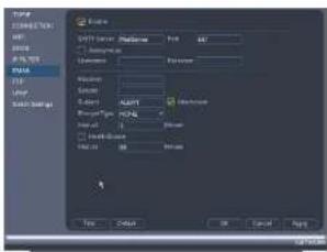
text_image
TYPE COMMENTS SET TIME OF WORK RISK TYPE Layer Multi-Strategy Name: COMMENTS SET TIME OF WORK RISK Time: 0.125 OK Cancel OK Cancel Help-
Check Enable to enable email notifications.
-
Configure the following:
-
SMTP Server: Enter the SMTP server address.
- Port: Enter the port used by the SMTP server.
- Anonymous: Check if your server supports anonymous log ins. Otherwise, leave
this unchecked. - User Name: Enter the SMTP user name.
- Password: Enter the SMTP password
- Receiver: Enter the email address that will receive alerts.
- Sender: Enter the sender's email address.
- Subject: Enter the subject line for the email alert.
- Attachment: Check to include a jpg image attachment of the camera.
Note
You must enable the Snapshot option for motion detection on each camera you would to receive attachments. For details, see 15.3.8 Configuring Motion Detection, page 57.
Using the Main Menu15
- Click

Network>Switch Settings.
- Conf
gure the IP Address, Subnet Mask, and Gateway for the internal PoE switch.
text_image
TCP/IP CYP/RESET M1 DNS FTP/USB URLS FTP FTP System Settings Default OK Cancel Help- Click OK. Click Save to save changes. The system will restart.
15.3.7 Event
The Event menu allows you to configure settings for motion detection, video loss, and system warnings.
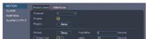
15.3.8 Configuring Motion Detection
Motion Detection events allow the system to mark footage that has motion. This allows you to quickly locate relevant footage through Search. You can also configure system responses to motion detection events, such as activating the system buzzer or sending an email alert.
To configure Motion Detection events:
Using the Main Menu15
- Click Setup next to Region to configure which areas of the image will be enabled for motion detection. A grid will appear over the camera's live view.
Motion Grid

text_image
Properties Support- Areas enabled for motion detection are shown in color and areas that are disabled are transparent.
- Hover the mouse at the top of the screen to select which motion area you would like to configure. You can set up to 4 motion detection areas and customize the sensitivity and threshold for motion detection separately for each area between 0 (lowest) and 100 (highest).
- The Sensitivity determines how sensitive the camera is to motion. For example, if the sensitivity is high, small amounts of motion are more likely to trigger an event. It is recommended to select a Sensitivity between 30\~70.
- The Threshold determines how much motion is required to trigger an event. If the amount of motion exceeds the threshold, an event occurs. It is recommended to select a Threshold between 10-50.
- Right-click when finished.
Note
It is recommended to have a second person walk in front of the camera to test different Sensitivity and Threshold settings to determine the best setting for your camera's location.
-
Under Anti-dither, enter the anti-dither time. After a motion event occurs and motion stops, if motion is detected within the anti-dither time, the system continues the motion event and includes the new motion within the first event, rather than creating a new
-
Configure the following system actions when motion is detected:
-
Alarm Out: Check the box to activate alarm output devices (not included) that will trigger when the selected channel detects motion. Select the alarm output devices that will be activated when motion is detected.
- Latch: Enter the number of seconds an alarm output device will activate after motion is detected.
• Show Message: Check to enable an on-screen pop-up when one of your cameras detects motion. On-screen pop-up shows the channels an event occurred on and the type of event. - Alarm Upload: Check to enable the system to upload alerts to FLIR Cloud™ Client.
- Send Email: Check to enable email alerts. You must configure email alerts before you will be able to receive them (see 15.3.5 Configuring Email Alerts, page 55).
- Channels: Select the channels that will record when motion is detected on the selected channel.
- PTZ Activation: Check to enable PTZ actions when motion is detected (PTZ camera required; not included). Click Setup to select which PTZ actions will be taken by each camera.
- Buzzer: Check to enable the system buzzer.
- Sequence: Check to enable a custom sequence mode when motion is detected on the selected channel. Then click the channels you would like to display in the custom sequence mode.
-
Snapshot: Check to save a snapshot when the camera detects motion.
-
Click OK to save changes.
15.3.9 Configuring Video Loss Settings
Video Loss occurs if the system loses connection to one of the cameras.
To configure Video Loss settings:
- From the Main Menu, click X and then click Event>Motion>Video Loss.

-
Configure the following to customize settings for video loss events:
-
Period: Click Setup to configure a schedule for video loss events. It is recommended to leave this on the default setting, so you can be alerted at any time one of your cameras loses video.
- Alarm Out: Select the alarm output devices (not included) that will trigger when video loss occurs.
- Latch: Enter the number of seconds an alarm output device will activate after video loss occurs.
- Show Message: Check to show a popup message on the monitor if one of your cameras loses video.
- Alarm Upload: Check to enable the system to upload alerts to FLIR Cloud™ Client.
- Send Email: Check to enable email alerts. You must configure email alerts before you will be able to receive them (see 15.3.5 Configuring Email Alerts, page 55).
- Channels: Click the checkbox to enable video recording when video loss occurs. You can then select the channels the system will record when video loss occurs on the currently selected channel.
- PTZ Activation: Check to enable PTZ actions when video loss occurs (PTZ camera required; not included). Click Setup to select which PTZ actions will be taken by each camera.
- Post_REC: Enter the number of seconds the system will record after video loss occurs.
- Snapshot: Click the box to enable snapshot recording when video loss occurs. You can then select which channels will save snapshots when video loss occurs on the currently selected channel.
- Sequence: Check to enable a custom sequence mode when video loss occurs on the selected channel. Then click the channels you would like to display in the custom sequence mode.
-
Buzzer: Check to enable the system buzzer when video loss occurs on the currently selected channel.
-
Click OK to save changes.
15.3.10 Configuring Alarm Input Devices
You can connect alarm input devices such as motion concerns (not included) or place break
-
Configure the following to activate an alarm input device:
-
Alarm In: Select the alarm input port the device is connected to.
- Enable: Check to enable the alarm input device connected to the selected port.
-
Type: Select Normal Open or Normal Close depending on the type of alarm input device you have.
-
Configure the following system responses and parameters for the alarm input device:
-
Period: Click Setup to configure the times of the week when the selected device will be activated. By default, the device will be activated 24/7.
- Anti-dither: Enter the anti-dither time. After the device triggers, if it triggers again within the anti-dither time, the system continues the event and includes the second activation within the first event, rather than creating a new event.
- Alarm Out: Check the box to activate alarm output devices (not included) and select the alarm output devices (not included) will be activated when the selected device is triggered.
- Latch: Enter the number of seconds an alarm output device will activate after the selected device is triggered.
- Show Message: Check to enable an on-screen pop-up when the selected device is triggered.
- Alarm Upload: Check to enable the system to upload alerts to FLIR Cloud™ Client.
- Send Email: Check to enable email alerts. You must configure email alerts before you will be able to receive them (see 15.3.5 Configuring Email Alerts, page 55).
- Channels: Select the channels that will record when the selected device is triggered.
- PTZ Activation: Check to enable PTZ actions when the selected device is triggered (PTZ camera required; not included). Click Setup to select which PTZ actions will be taken by each camera.
- Sequence: Check to enable a custom sequence mode when the alarm device triggers. Then click the channels you would like to display in the custom sequence mode.
- Buzzer: Check to enable the system buzzer.
- Snapshot: Check to save a snapshot.
- Click OK to save changes.
To access the Alarm Output menu:
- From the Main Menu, click ✗ and then click Event>Alarm Output.
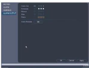
text_image
AVOC AVOC AVOC 0.01 AVOC 0.01/0.01 Auto Cut: 25 Stroke: 0 Manual: 0 Stop: 0 Down: 0 Auto Release: OK OK Cancel ApplyTo control alarm output devices:
- To enable alarm output devices, select Schedule or Manual for each device you would like to enable. Select Stop to disable the alarm output device. Click OK to save changes.
• To manually disable activated alarm devices, click OK under Alarm Release.
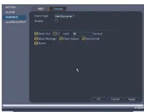
15.3.12 Configuring Hard Drive Warnings
Hard drive warnings will notify you if an issue is detected with the hard drive.
To configure hard drive warnings:
- From the Main Menu, click ✗ and then click Event>Warning>HDD.
-
Configure the responses the system will take when the selected event occurs:
-
Alarm Out: Activate selected alarm out devices. Use Latch to select the number of seconds the alarm out device will be activated.
• Show Message: Show a popup message on the monitor. - Alarm Upload: Check to enable the system to upload alerts to FLIR Cloud™ Client.
- Send Email: Check to enable email alerts. You must configure email alerts before
you will be able to receive them (see 15.3.5 Configuring Email Alerts, page 55). -
Buzzer: Check to activate the system buzzer.
-
Click OK to save changes.
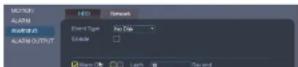
15.3.13 Configuring Network Warnings
Network warnings will notify you if your system loses connection to the Internet or local network or if there is an issue on your network.
To configure network warnings:
- From the Main Menu, click X and then click Event>Warning>Network.
text_image
NEW Close Type: New Document Open Show Out Lock W Guard Show Messages Open Upscale Send Call Show OK Cancel Apply- Under Event Type, select the event type you would like to configure.
- Net Dissemination: The model has last operation in the animal.
15.3.15 Configuring the Video Recording Schedule
You can set a custom recording schedule according to your needs. For example, you can set the system to record continuously during business hours and record on motion detection only outside of business hours.
A custom recording schedule helps reduce the amount of hard drive space required, increasing the time your system can retain recordings.
To configure the video recording schedule:
- From the Main Menu, click ✕ and then click Storage>Schedule>Record.
- Under Channel, select the channel you would like to configure or select All.
- Configure the schedule as needed:
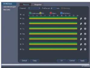
text_image
SCHEDULE LOG MANAGER RECORD Record Preview Control Default OK Cancel Apply 100% 100% 100% 100% 100% 100% 100% 100% 100% 100% 100% 100% 100% 100% 100% 100% 100% 100% 100% 100% 100% 100% 100% 100% 100% 100%- Check Continuous or MD (motion detection) to select the recording type you would like to configure.
- Click and drag on each day to customize the recording schedule. The schedule is set up as a grid, which each block representing one hour.
- Click next to All to link the recording schedules for all days. The icon for a day
Using the Main Menu15
To configure pre-recording:
- From the Main Menu, click ✕ and then click Storage>Schedule>Record.

text_image
MACHINE RICHMONS RICHMONS Control OK Cancel Help OK Cancel Help OK Cancel OK OK Cancel OK OK Cancel OK OK Cancel OK OK Cancel OK OK Cancel OK OK Cancel OK OK Cancel OK OK Cancel OK OK Cancel OK OK Cancel OK OK Cancel OK OK Cancel OK OK Cancel OK OK Cancel OK OK Cancel OK OK Cancel OK OK Cancel- Under Channel, select the camera you would like to configure or select All.
- Under PreRecord, select the duration for pre-recording.
- Click OK to save settings.
15.3.17 Configuring the Snapshot Schedule
You can set a schedule for recording snapshots from the cameras.
To set up the snapshot schedule:
- From the Main Menu, click X and then click Storage>Schedule>Snapshot.

-
Configure the schedule as needed:
-
Check Continuous or MD (motion detection) to select the recording type you would like to configure.
- Click and drag on each day to customize the recording schedule. The schedule is set up as a grid, which each block representing one hour.
- Click next to All to link the recording schedules for all days. The icon for a day changes to when it is linked. You can also click the boxes next to individual days to link them to each other. If the recording schedule is linked, changes made to one of the days will apply to every day that is linked.
- Click 📋 to disable all recording of the selected type on the selected day.
-
Click 🖱️ if you need to set a more precise schedule down to the minute.
-
Click OK to save changes.
15.3.18 Configuring Holidays
You can set certain days as holidays. Holidays have a special recording schedule.
To configure holidays:
- From the Main Menu, click X and then click Setting>General>Holiday.

text_image
From the Main Menu, click X and the Command Enter Paste Properties Account Configuration Package PAGEUsing the Main Menu15
- Configure the following:

text_image
Add New Settings Add New Item New Item Add Copy Add New Add New Add New Add New Add New• Holiday Name: Enter a name for this holiday.
- Repeat Mode: Select Once Only for the holiday to occur only this year or All-Year for the holiday to be repeated each year.
- Holiday Range: Select Date to select a specific date, or select Week to select holidays based on which week they fall on.
- Click Add. Now that you have added a holiday, an extra holiday setting is added to the recording schedule.
Note
You cannot delete holidays, but you can disable them by selecting Stop under the Status drop-down and then click Apply.
15.3.19 Formatting the Hard Drive
The HDD Manager menu allows you to format the hard drive. If you install a new hard drive, you must format the hard drive using the system before you will be able to record.
To format the hard drive:
Using the Main Menu15
- Click OK to save changes. The system will restart to complete the formatting process.
15.3.20 Configuring Hard Drive Type
The system supports the following hard drive types:
- Read-write HDD: Normal recording hard drive.
- Read-only HDD: The system can playback data from this hard drive, but it will not record to it.
- Mirror HDD: The hard drive will be used for mirror recording only. You must set up mirroring recording before this feature will work.
To set the hard drive type:
- From the Main Menu, click ✗ and then click Storage>HDD Manager.
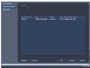
text_image
SUPPORT HOLD MANAGER RETURN Device Name: Type: Normal Status: Normal Date: 01/12/2014.06.03 Name: Normal OK Cancel Apply F51089- Click the hard drive you would like to configure.
- Under Type, select Read-write HDD, Read-only HDD, or Mirror HDD.
- Click OK to save changes. The system will restart to complete this operation.
15.3.21 Setting up Hard Drive Mirroring (Advanced)
A mirror hard drive can be used to automatically backup video footage recorded to the re-
Using the Main Menu15
Note
- The mirror hard drive must be as large or larger than primary hard drive to backup all recordings.
- HDD mirroring begins from when mirror hard drive is installed and configured.
- Two hard drives must be installed in the system to use HDD mirroring. For details on installing hard drives, see 22 DNR400 Series Hard Drive Installation, page 170.
To set up hard drive mirroring:
- From the Main Menu, click X and then click Storage>HDD Manager.
- Click the Type drop-down under the second hard drive and select Mirror HDD.
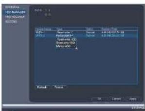
text_image
INTERNAL HOT MULDER HOT COUVER RETURN Material NO: Material NO Material NO Material NO Material NO Material NO Material NO Material NO Material NO Material NO Material NO Material NO Material NO Material NO Material NO Material NO Material NO Material NO Material NO Material NO Material NO Material NO Material NO Material NO Material NO Material NO Material NO Material NO Material NO Material NO Material NO Material NO Material NO Material NO Material NO material NO material NO material NO material NO material NO material NO material NO material NO material NO material NO material NO material NO material NO material NO material NO material NO material NO material NO material NO material NO material NO material NO material NO material NO material NO material NO material NO material NO material NO material NO material NO material NO material NO material No. Material No. Material No. Material No. Material No. Material No. Material No. Material No. Material No. Material No. Material No. Material No. Material No. Material No. Material No. Material No. Material No. Material No. Material No. Material No. Material No. Material No. Material No. Material No. Material No. Material No. Material No. Material No. Material No. Material No. Material No. Material No. Material No. Material No. MaterialNo. MaterialNo. MaterialNo. MaterialNo. MaterialNo. MaterialNo. MaterialNo. MaterialNo. MaterialNo. MaterialNo. MaterialNo. MaterialNo. MaterialNo. MaterialNo. MaterialNo. MaterialNo. MaterialNo. MaterialNo. MaterialNo. MaterialNo. MaterialNo. MaterialNo. MaterialNo. MaterialNo. MaterialNo. MaterialNo. MaterialNo. MaterialNo. MaterialNo. MaterialNo. MaterialNo. MaterialNo. MaterialNo. MaterialNo. MaterialN0.1.1.2.3.4.5.6.7.8.9.10.11.12.13.14.15.16.17.18.19.20.21.22.23.24.25.26.27.28.29.30.31.32.33.34.35.36.37.38.39.40.41.42.43.44.45.46.47.48.49.50.51.52.53.54.55.56.57.58.59.60.61.62.63.64.65.66.67.68.69.70.71.72.73.74.75.76.77.78.79.80.81.82.83.84.85.86.87.88.89.90.91.92.93.94.95.96.97.98.99.100.
CAUTION
Setting a hard drive for mirroring erases all data on the hard drive. This step cannot be undone.
- Click OK to apply changes. Click Yes to confirm. The system will format the hard drive
and restart.
- When the system restarts, click and then click Storage>Schedule>Record.
- Under Channel. select the channel you would like to enable for mirror recording, then
can reduce the amount of wear on the hard drives and may extend the life of the hard drives.
Note
- Two hard drives must be installed in the system to use hard drive groups, and both hard drives must be formatted as Read-write hard drives. For details on installing hard drives, see 22 DNR400 Series Hard Drive Installation, page 170.
To configure hard drive groups:
-
From the Main Menu, click X and then click Storage>HDD Advance>HDD Setting.
-
Under HDD Group, assign a group to each hard drive. To set up two hard drive groups, assign one hard drive to group 1 and the other to group 2.

text_image
Schematic HDD Manager HDD MANAGER HDD AG/AG/AG RETURN HDD HDD Group HDD HDD Group 1 1...2...3... Cancel Off Apply-
Click OK. The system will restart to apply changes.
-
When the system restarts, you must decide which channels will record to each hard drive group.
-
From the Main Menu, click ✗ and then click Storage>HDD Advance>Main
Using the Main Menu15
- Click the Sub Stream tab. For each channel, select the hard drive group you would like to record the sub stream (reduced quality) video and then click Apply.

text_image
CHANNEL HE-MAAGER HE-AQUAIC WARNING HD: 5000000000000000000000000000000000000000000000000000000000000000000000000000000000000000000000 Channel/HD Group Channel/HD Group Channel/HD Group Channel/HD Group Channel/HD Group Channel/HD Group Channel/HD Group Channel/HD Group Channel/HD Group Channel/HD Group Channel/HD Group Channel/HD Group Channel/HD Group Channel/HD Group Channel/HD Group Channel/HD Group Channel/HD Group Channel/HD Group Channel/HD Group Channel/HD Group Channel/HD Category Channel/HD Category Channel/HD Category Channel/HD Category Channel/HD Category Channel/HD Category Channel/HD Category Channel/HD Category Channel/HD Category Channel/HD Category Channel/HD Category Channel/HD Category Channel/HD Category Channel/HD Category Channel/HD Category Channel/HD Category Channel/HD Category Channel/HD Category Channel/HD Category Channel/HD Category Channel/HD Categories- Click the Picture tab. For each channel, select the hard drive group you would like to record snap shots and then click Apply.
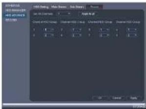
text_image
ADD Settings Add Settings Close Settings Close Mode Close Mode Group Close Mode Group Close Mode Group 100% 100% 100% 100% 100% 100% 100% 100% 100% 100% 100% 100% 100% 100% 100% 100% 100% 100% 100% 100% 100% 100% 100% 100% 100% 100%15.3.23 Configuring General System Settings
-
Configure the following:
-
Device Type: Shows the model number of your system.
• Device No.: Select the remote control address of the system. See 8.1 Setting the
Remote Control Address, page 17. - Language: Set the system languages. Available options are English, French, and Spanish.
• Video Standard: Select NTSC (North America) or PAL (Europe). - HDD Full: Select Overwrite for the system to overwrite the oldest recordings when the hard drive is full or select Stop Record for the system to stop recording when the hard drive is full.
- Pack Duration: Select the length (in minutes) of video files stored on the system. For example, if this is set to 30 minutes, the system will create a new video file for each 30 minutes of continuous recording.
- Instant Playback: Select the amount of time (in minutes) the system will go back when instant playback is activated in live view.
- Auto Logout: Select the idle time (in minutes) before the system will logout the current user.
- IPC Time Sync: Select how often (in hours) the NVR will update the time on the IP cameras.
- Navigation Bar: Check to enable the Navigation Bar that comes up when you left click in live view.
- Startup Wizard: Check to enable a setup wizard when you start up the system.
-
Mouse Speed: Use the slider to adjust the mouse speed.
-
Click OK to save changes.
15.3.24 Setting the Monitor Resolution (Display)
The Display menu allows you to configure the systems monitor resolution and other display settings.
To set the monitor resolution:
- From the Main Menu, click ✗ and then click Setting>Display>Display.
Using the Main Menu15
To configure other display settings:
- From the Main Menu, click × and then click Setting>Display>Display.
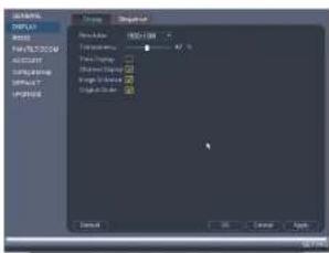
text_image
BIMINUM HOLDEN MINT File POSTLOGIE POSTLOGIE COMPOSING POSTLOGIE POSTLOGIE Name: H10000000000000000000000000000000000000000000000000000000000000000000000000000000000000000000000000000 Default OK Cancel Help- Configure the following:
• Transparency: Select the menu transparency.
• Time Display: Check to show the time on the monitor.
- Channel Display: Check to show the channel names on the monitor.
- Image Enhance: Check for the system to digitally improve the video quality on the
live display. This setting does not affect recordings
- Original Scale: Check to set the system to show the true aspect ratio of the cam-
eras on the live display. This may add black bars to the top and bottom of the imag
- Click OK to save changes.
15.3.25 Saving Your System Configuration to a USB Thumb Drive
The system allows you to save your current system configuration to a USB thumb drive (not included). This is useful if you want to backup your current settings.
Note
This function only saves settings created in system menus. It does not save or backup any video.
Using the Main Menu15
-
Under Device Name, select the USB device where you would like to save the configuration.
-
Click EXPORT to save your current system configuration.
To restore a saved system configuration:
-
Insert a USB thumb drive (not included) with a saved system configuration into one of the USB ports.
-
From the Main Menu, click ✗ and then click Setting>Config Backup
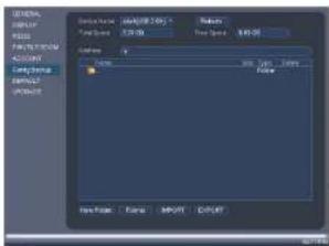
text_image
文件名(N): C:\Program Files\1\r2\Program Files\2\r3\Program Files\3\r4\Program Files\4\r5\Program Files\5\r6\Program Files\6\r7\Program Files\7\r8\Program Files\8\r9\Program Files\9\r10\r11\r12\r13\r14\r15\r16\r17\r18\r19\r20\r21\r22\r23\r24\r25\r26\r27\r28\r29\r30\r31\r32\r33\r34\r35\r36\r37\r38\r39\r40\r41\r42\r43\r44\r45\r46\r47\r48\r49\r50\r51\r52\r53\r54\r55\r56\r57\r58\r59\r60\r61\r62\r63\r64\r65\r66\r67\r68\r69\r70\r71\r72\r73\r74\r75\r76\r77\r78\r79\r80\r81\r82\r83\r84\r85\r86\r87\r88\r89\r90\r91\r92\r93\r94\r95\r96\r97\r98\r99\r100-
Under Device Name, select the USB device.
-
Click the folder with the configuration files you would like to restore. Configuration file folders are labeled "Config" and then the time and date the configuration was saved (e.g. Config 20140425103727).
-
Click IMPORT to restore the system configuration.
-
Click OK to confirm. The system will restart to complete the operation.
15.3.26 Setting the System to Factory Defaults
The Default menu allows you to reset the system to factory default settings.
To reset the system to factory default settings:
Using the Main Menu15
15.3.27 Upgrading Firmware from USB
Firmware upgrades provide enhanced functionality. The system will automatically check for firmware upgrades if it is connected to the Internet. The system also supports firmware upgrades from a USB thumb drive (not included).
To upgrade firmware from a USB drive:
- Download the firmware upgrade from www.flirsecurity.com/pro.
- Extract the firmware file and copy the firmware to a blank USB thumb drive.
Note Do not have any folders on the USB thumb drive—just the firmware file.
-
Insert the USB thumb drive to a USB port on the system.
-
Right-click and then click Main Menu. Click >Setting>Upgrade.

text_image
GENERAL INPUT FLOOR FAT/1200M ADDRESS Carry Backup ADDRESS LOAD Cancel Help If you could use a computer system to please you and I'll buy any other item or your own device. You can't check your computer system to get your own device.-
Click Start.
-
Select the firmware file on the USB drive and click Start.
WARNING
Using the Main Menu15
15.4 Shutdown
Use the Shutdown menu to shutdown, restart, or log out of the system.
To access the Shutdown menu:
- From live view, right-click and select Main Menu.
-
Enter the system User Name (default: admin) and Password (default: 000000) and click OK.
-
Click >Shutdown.
-
Select one of the following:

text_image
SHUTDOWN Shutdown Logout Robast- Logout: Log out the account that is currently active.
- Shutdown.
- Restart.
Connecting to Your System Over the Internet on PC or Mac
This system features connectivity using the exclusive FLIR Cloud™. This cloud-enabled service allows for Internet connectivity without requiring any network configuration. Up to 3 devices may connect to the system at the same time.
Note
- Except where noted, the PC and Mac instructions in this section are the same.
- For smartphone/tablet setup, see 18 Connecting to your System Using Smartphone or Tablet Apps.
page 108 - For the latest list of supported apps and devices, visit www.flirsecurity.com/pro.

text_image
FLIR HOLD FLIR HOLD16.1 System Requirements
Your system must meet the system requirements below:
| Description Requirement | |
| CPU Core 2 Duo 3.0GHz | |
| Operating System WindowsTM 8/7/Vista |
- Reconnect the power adapter to power the system back on.
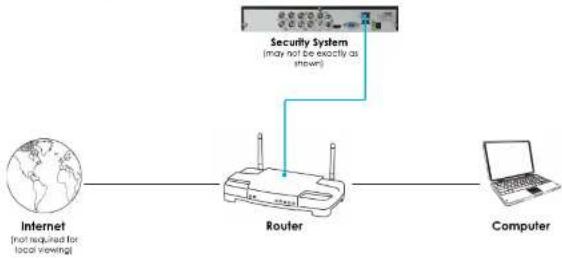
flowchart
graph LR
    A["Internet\n(not required for local viewing)"] --> B["Router"]
    C["Computer"] --> B
    B --> D["Security System\n(may not be exactly as shown)"]
16.3 Step 2 of 3: Obtain the system's Device ID
The Device ID is a unique code that allows your system to handshake with FLIR Cloud™ servers for a secure connection over the Internet.
To find the Device ID:
- The Device ID is located on a sticker on the system.
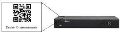
text_image
Device ID: xxxxxxxxxx- Write down the Device ID of the system.
16.4 Step 3 of 3: Connect to the System Over the Internet
- Log into the Client Software using the Client Software user name (default: admin) and password (default: admin) and then click Login.

text_image
FLIR Cloud User NAME: admin Password: ****** Belarusian Password { Login } { Fail }- Click Add Device.

text_image
FLIR audio 文件(F) 100% 200% 300% 400% 500% 600% 700% 800% 900% 1000% 1100% 1200% 1300% 1400% 1500% 1600% 1700% 1800% 1900% 2000% 2100% 2200% 2300% 2400% 2500% 2600% 2700% 2800% 2900% 3000% 3100% 3200% 3300% 3400% 3500% 3600% 3700% 3800% 3900% 4000% 4100% 4200% 4300% 4400% 4500% 4600% 4700% 4800% 4900% 5000% 5100% 5200% 5300% 5400% 5500% 5600% 5700% 5800% 5900% 6000% 6100% 6200% 6300% 6400% 6500% 6600% 6700% 6800% 6900% 7000% 7100% 7200% 7300% 7400% 7500% 7600% 7700% 7800% 7900% 8000% 8100% 8200% 8300% 8400% 8500% 8600% 8700% 8800% 8900% 9000% 9100% 9200% 9300% 9400% 9500% 9600% 9700% 9800% 9900% 100- Enter the following:
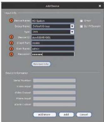
text_image
Add Device Device Name: HD System Group Name: Default Group Type: CMV Device ID: DevS38-05-001 Cust Part: 35000 Base Name: admin Password: ****** Reference Info. Device Information Serial Number: In-line Input Video Output Alarm Input Alarm Output Add More Add Cancel5.1. Device Name: Choose a name for your system of your choice.
5.2. Device ID: Manually enter the Device ID printed on the label.
5.3. Client Port: Enter the Client Port (default: 35000).
5.4. User Name: Enter the system User Name (default: admin).
5.5. Password: Enter the system Password (default: 000000).
- Click Add. If this is the first time you are connecting, you will be prompted to change the system password.
8.
Click


- Click and drag Default Group to the display window to open your cameras in live view.

text_image
FLIR.dwg FLIR.dwg - 100% FLIR.dwg - 100%Congratulations! You can now connect over the Internet to view and playback video on your computer.
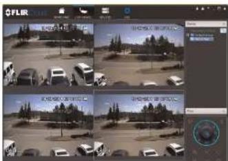
text_image
Screenshot of a video editing interface showing a grid of surveillance feeds with vehicle images and Chinese text labels.Using FLIR Cloud™ Client for PC or Mac
FLIR Cloud™ Client allows you to connect to multiple systems from a PC or Mac.
17.1 Home Page
The Home Page allows you to access all the tabs within the software. Each tab allows you to access different features.
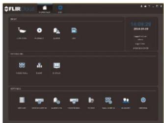
text_image
FLIR Local 14:09:29 2014-08-09 USEUM ITEMS CREATE TABLES CREATE VIEW CREATE VIEW SETT NC3 USEUM ITEMS CREATE VIEW CREATE VIEWTo open tabs:
Click a tab from the Home Page to open it or click the button at the top of the screen from within any tab to open a new tab.
17.2 Live View
The Live View tab is where you can view live video from connected systems.
To view live video from a system:
-
Click 📄 and then click to create a Live View tab.
-
Click and drag a DVR, NVR, group, or individual camera to open live video. To access individual camera, you can click + to expand groups or customs
17.2.1 Live View Controls

text_image
FLIR ① ② ③ ④ ⑤ ⑥ ⑦- Live display: Double-click to expand the area. Right-click to access additional options. Hold the mouse over the display area to access the camera toolbar.
Camera toolbar:

text_image
Sub Stream(205kbps, 352*240) ① ②③④⑤⑥⑦⑧1.1. Streaming quality: Shows the bitrate and resolution for the stream, and shows if display is showing the Sub Stream or Main Stream.
1.2. Manual recording: Click to start/stop manual recording.
1.3 Cnanchat Click to save a anochet

Save view: Click to save the current display layout and open cameras as a view. n enter a name for the view.

Start/stop tour: Click to start the tour. During the tour the client will cycle through saved views every few seconds. Click again to stop the tour.
PTZ Controls: Controls for PTZ cameras (not included). See 17.3 Controlling PTZ Cameras, page 85 for details.
View: Click View to access view menu. Then double-click on a view to open it in the display area.
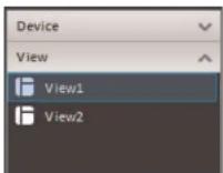
- Devices: Shows a list of groups, cameras, and systems connected to the client. Drag items to the display area to open live video. Right-click to view additional options.
17.2.2 Opening Live View in Multiple Monitors
If your computer has multiple monitors, you can open more than one Live View tab and move them to secondary monitors. This allows you to monitor cameras on multiple monitors at the same time.
Note
Using multiple monitors significantly increases the amount of computing resources necessary to run the application and may affect performance.
To open Live View in multiple monitors:
- Click and drag the tab outside of the client window to create a new window. You can drag the window to one of the secondary monitors.
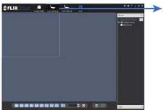
text_image
FLIR Status Bar FLIR Progress Bar Control Panel Control Panel Control Panel Control Panel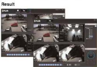
If you have PTZ cameras (not included), you can control them using the client.
Note
PTZ controls:
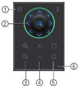
text_image
Diagram of a device control panel with numbered labels pointing to various function buttons and display areas.- Open menu: Click to open camera OSD menu controls. This feature may not be supported for all camera models.
- Move camera: Click the arrows to move the camera. Click to open dynamic zoom mode. Then click and drag in the video area to zoom in the camera on an area.
- Zoom +/-: Click to zoom the camera in and out.
- Focus +/-: Click to increase/decrease the focus.
- INS +/- Click to increase/decrease the INS.
- Advanced: Click to access advanced PTZ controls.
17.3.1 PTZ Presets
Presets will save a camera position for quick retrieval.
To add presets:
- Select the number of the preset you would like to add.
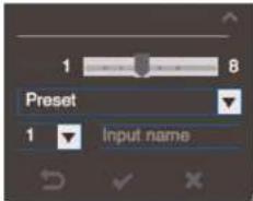
text_image
1 8 Preset 1 Input name- Move the camera to the desired position.
- Click to save the current position as a preset.
To go to a saved preset:
- Select the preset number from the list or click to go to the currently selected preset.
17.3.2 PTZ Tours
Tours will cycle through a set of presets.
To configure a PTZ tour:
- Click ▼ to open the Advanced controls. Select Tour.
- Click

- Use the chart to select which presets you would like to include in the tour and the order of presets.
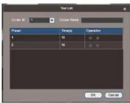
text_image
User Lab Close Image 1 Close Text Power Speed: Operation 1 50 30 OK Cancel- Preset: Select the preset number.
- Time(s): Enter the time in seconds the camera will remain on the selected preset.
-
Operation: Click + to add a preset to the tour. Click to delete a preset from the tour.
-
Click OK to save changes.
To run a PTZ tour:
- Select the tour number and cli

17.3.3 PTZ Pattern
Patterns automatically cycle the camera between two positions.
To create a pattern:
- Click ▼ to open the Advanced controls. Select Pattern.
- Select the number of the pattern you would like to set up.
17.3.4 PTZ Scan
Scan automatically cycles between a left and right point.
To set up scan mode:
- Click ▼ to open the Advanced controls. Select Scan.

- Move the camera to the desired left position and click.
- Move the camera to the desired right position and click.
To run scan mode:
- Click
17.3.5 PTZ Pan
Pan makes the camera continuously pan 360°.
To run Pan mode:
- Click ▼ to open the Advanced controls. Select Pan.
- Click 🔒.
17.4 Playback
To playback video:
- Check the channels you would like to play back from in the Device List.
- Under Type, check the file types you would like to search for.
• All: All recordings.
• General: Continuous recordings.
• MD: Motion recordings.
- Alarm: Alarm recordings. Your system must support alarm devices (not included) to use this feature.
- Under Stream, select Main Stream to search for Main Stream recordings (high qual-
ity) or Sub Stream to search for Sub Stream recordings (smaller file size). - Select the start time and end time for your search under From and To. You may not
search more than 24 hours of video. - Click Search. Wait for the client to find video saved to the system
- Click Search. Wait for the client to find video saved to the system.
- Click inside the play back bar to start playback.

text_image
FLIR FLIR FLIR FLIR FLIR FLIR FLIR FLIR FLIR FLIR FLIR FLIR FLIR FLIR FLIR FLIR FLIR FLIR FLIR FLIR FLIR FLIR FLIR FLIR FLIR FLIR FLIR FLIR FLIR FLIR FLIR FLIR FLIR FLIR FF1000000000000000000000000000000000000000000000000000000000000000000000000000000000000000000000000000017.5 Playback Controls
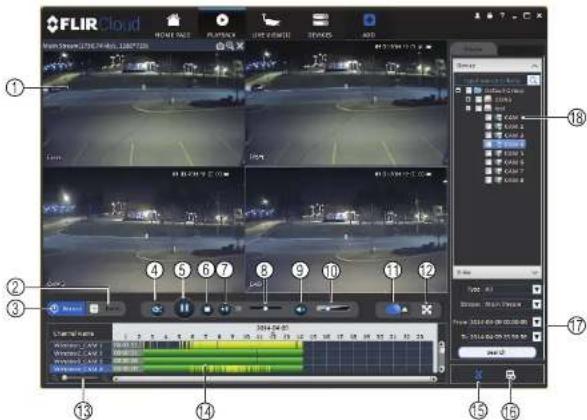
text_image
FLIR Cloud 1 2 3 4 5 6 7 8 9 10 11 12 13 14 15 16 17 18- Display area: Double-click to expand/return to split-screen mode. Hold the mouse over the display area to open the camera toolbar.

- Snapshot: Click to save a snapshot.
-
Digital zoom: Click to enable digital zoom mode. Then click and draw to zoom in. Click and
-
Download list: Click to see a list of files you have downloaded and the progress of files that are currently downloading.
- Search: Search for video on the selected channels based on the search parameters you set.
- Device list: Select the channels you would like to search or playback video from.
17.6 Downloading Video to your Computer Hard Drive
You can download video to your computer hard drive to save important events or share them. It is recommended to download video of important events as soon as possible to ensure they are not overwritten by new recordings.
Note
PC Users: You may need to run FLIR Cloud™ Client as an administrator to download files to your hard drive.
To download video files:
- Start playing back video using the steps in 17.4 Playback, page 89.
- Click to start a video clip at the current playback time. Click to stop the video clip.
- Configure the following save options:

• Path: Use the default save folder or click Browse to select a different folder.
- File Format: Select Original Format to save to .dav format (requires the video player). Select AVI to save files to .avi format (can be played in VLC Media Player).
Note
17.7 Alarm
The Alarm menu allows you to view a list of alarms received by the client software.
Note
You must set up alarms in the Alarm CFG menu before they will appear in this list. See 17.12 Alarm CFG,
page 98 for more details.
To access Alarms:
- Click and then click
Alarm menu overview:

text_image
FLIR ① ② ③ ④- Number of alarms: Shows the number of open alarms.
- Alarm list: Shows the list of alarms and information on when they occurred and which
systems and channels triggered them - Alarm Process: You can close alarms by selecting one of the options and clicking OK.
- Options: Check to enable the following:
- Display Link Video: Open live video to monitor alarms on a continuous basis.
To view client logs:
- Click Client Log to view logs for the client software.

text_image
FLIR GROUP File Edit View Insert Help Add View Insert Help Add View Insert Help Add View Insert Help Add View Insert Help Add View Insert Help Add View Insert Help Add View Insert Help Add View Insert Help Add View Insert Help Add View Insert Help Add View Insert Help Add View Insert Help Add View Insert Help Add View Insert Help Add View Insert Help Add View Insert Help Add View Insert Help Add View Insert Help Add View Insert Help Add View Insert Help Edit View Insert Help Edit View Insert Help Edit View Insert Help Edit View Insert Help Edit View Insert Help Edit View Insert Help Edit View Insert Help Edit View Insert Help Edit View Insert Help Edit View Insert Help Edit View Insert Help Edit View Insert Help Edit View Insert Help Edit View Insert Help Edit View Insert Help Edit View Insert Help Edit View Insert Help Edit View Insert Help Edit View Insert Help Edit View Insert Help Add View Insert Help Add View Insert Help Add View Insert Help Add View Insert Help Add View Insert Help Add View Insert Help Add View Insert Help Add View Insert Help Add View Insert Help Add View Insert Help Add View Insert Help Add View Insert Help Add View Insert Help Add View Insert Help Add View Insert Help Add View Insert Help Add View Insert Help Add View Insert Help Add View Insert Help All Users: 123,000 (123,000) (123,000) (123,000) (123,000) (123,000) (123,000) (123,000) (123,000) (123,000) (123,000) (123,000) (123,000) +/-- Configure the following:
- Start Time/End Time: Select the start and end times to search for logs. - Log Type: Select the type of logs to search for.
- Click Search.
To view logs from connected systems:
- Click Device Log to view logs from connected systems.

- Configure the following:
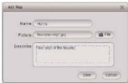
text_image
Add Map Name: Hidoc Picture: Newshing.psd Describe: Newshing of the House? Save Cancel• Name: Enter a name for your e-map of your choice.
- Picture: Click File and then select a .png, .bmp, or .jpg image on your computer to use as the e-map.
- Describe (optional): Enter a text description of the e-map.
-
Click Save.
-
Click and drag cameras from the device list to place them on the map.
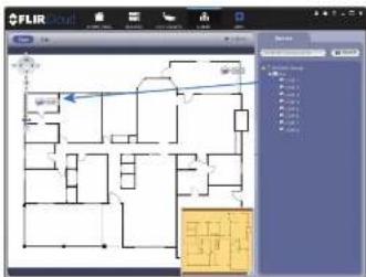
text_image
FLIR GROUP File Edit View Help Map View Tools Help Map View Tools Help Map View Tools Help Map View Tools Help Map View Tools Help Map View Tools Help Map View Tools Help Map View Tools Help Map View Tools Help Map View Tools Help Map View Tools Help Map View Tools Help Map View Tools Help Map View Tools Help Map View Tools Help Map View Tools Help Map View Tools Help Map View Tools Help Map View Tools Help Map View Tools Help Map View Tires Help Map View Tires Help Map View Tires Help Map View Tires Help Map View Tires Help Map View Tires Help Map View Tires Help Map View Tires Help Map View Tires Help Map View Tires Help Map View Tires Help Map View Tires Help Map View Tires Help Map View Tires Help Map View Tires Help Map View Tires Help Map View Tires Help Map viewTo open cameras from the e-map:
-
Click View.
-
Double-click cameras on the map to open live video.

text_image
FLIRDevices overview:
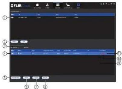
text_image
FLIR Cloud ① ② ③ ④ ⑤ ⑥ ⑦ ⑧- Devices Found: Shows systems that are connected to the same network as the computer where the client is installed. Once you connect to the system, it moves to the bot tom of the screen.
- Search: Refresh the list of systems connected to the network.
- Add: Add checked systems to the client software.
- Device list: Shows a list of systems connected to the client software, and shows which systems are online.
- Add Device: Add a remote system using a Device ID or IP/DDNS address.
- Delete: Delete the selected system
- Import: Import a list of systems from a saved .xml file.
- Export: Export a list of currently connected systems to an .xml file. This is useful if you need to re-install the software or if you want to open the same list of systems on a different computer.
- Delete: Delete system.
- Manual connect/disconnect: Manually connect/disconnect the system.
11 Edit Edit the connection details for the system
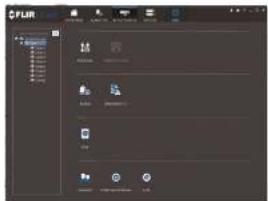
text_image
FLIR FLIR FLIR FLIR FLIR FLIR FLIR FLIR FLIR FLIR FLIR FLIR FLIR FLIR FLIR FLIR FLIR FLIR FLIR FLIR FLIR FLIR FLIR FLIR FLIR FLIR FLIR FLIR FLIR FLIR FLIR FLIR FLIR FLIR FUR FUR FUR FUR FUR FUR FUR FUR FUR FUR FUR FUR FUR FUR FUR FUR FUR FUR FUR FUR FUR FUR FUR FUR FUR FUR FUR FUR FUR FUR FUR FUR FUR FURNote
The settings available depend on the model of system you have.
17.12 Alarm CFG
The Alarm CFG menu allows you to configure alarms for the client software. The client software will alert you by popping up live video and playing sound alerts.
Note
Alarm upload must be enabled on the system in order for it to send the alarm to the client software.
To create alarms:
- Click

and then click

- Click Add to create a new alarm.

- In the Alarm sources menu, you set up the parameters that trigger the alarm.
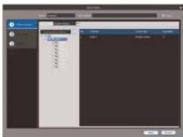
text_image
Screenshot of a software interface with a dropdown menu and toolbar, showing text options like 'Top 1', 'Bottom 1', and 'Left/Right' in Chinese.- Under Alarm Type, select the alarm type that will trigger an alarm. For example, you can select Motion Detect for the alarm to be triggered by motion.
- Select the systems or channels you would like to trigger an alarm. Continuing the example, if CAM 1 is selected, the alarm will be triggered if there is motion on CAM 1.
-
Click Next.
-
In the Alarm link menu, you set up the responses to alarms. Select the channels that will pop up or alarm out devices (not included; not all systems support alarm out devices) that will be triggered by an alarm. For each channel selected, configure the following:
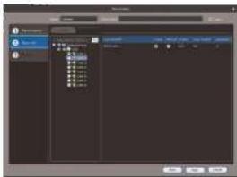
text_image
Screenshot of a software interface showing a dialog box with file selection and properties panel• Video: Pop up a window with live video from the selected channel, like the one below.

natural_image
Screenshot of a video editing software interface showing a black-and-white photo of a car parked on a road, with no visible text or symbols in the main image area.• Record: Record video from the selected channel.
Note PC Users: You may need to run the client software as admin to record.
To manage alarms:

text_image
Screenshot of a software interface with labeled components, showing menu bar and toolbar icons- Export: Export current list of alarms as an xml file.
- Import: Import list of alarms.
- Delete: Delete selected alarm.
- Add: Add new alarm.
- Alarms.
- On/off: Click to enable/disable alarm.
- Delete: Click to delete alarm.
- Edit: Click to edit alarm settings.
17.13 Tour & Task
The Tour & Task menu is where you can set up custom views for the system. You can also set up tours, which sets the client to automatically cycle through views.
To start a tour:
- Click in Live View to start a tour. The live view will automatically cycle through all views you have got up in the Tour & Task menu. Click again to stop the tour.
- Under Name, enter a name for your view.
- Under Stay Time, enter the number of seconds the view will be shown before the client switches to the next view.
- Select the split-screen mode you would like to use for the view and then click and drag channels to the empty grid areas to select channels to be shown in the view.

text_image
Empty Empty Empty- Click Save to save the view. Or click Add More to save the view and create another view.
17.14 Account
The Account menu is where you can set up user accounts and passwords for the client software. To simplify management, you can group user accounts according to role. A role determines the permissions an individual user account can have.
To access the account menu:

17.14.1 Managing User Accounts
To create a user account:
- Click Add.

- Configure the following settings for the user account:
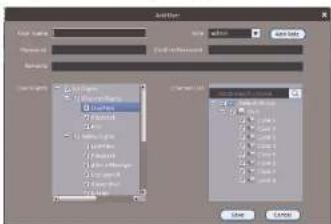
text_image
AutoForm Material Name: Auto Preview ID: Auto-03-0000000000000000000000000000000000000000000000000000000000000000000000000000000000000000000000000000 Auto Form 1.2.1.1 (Layered to Image) 1.2.1.1 (Layered to Image) 1.2.1.1 (Layered to Image) 1.2.1.1 (Layered to Image) 1.2.1.1 (Layered to Image) 1.2.1.1 (Layered to Image) 1.2.1.1 (Layered to Image) 1.2.1.1 (Layered to Image) 1.2.1.1 (Stacked to Image) 1.2.1.1 (Stacked to Image) 1.2.1.1 (Stacked to Image) 1.2.1.1 (Stacked to Image) 1.2.1.1 (Stacked to Image) 1.2.1.1 (Stacked to Image) 1.2.1.1 (Stacked to Image) 1.2.1.1 (Stacked to Image) 1.2.2.2 (Layered to Image) 1.2.2.2 (Layered to Image) 1.2.2.2 (Layered to Image) 1.2.2.2 (Layered to Image) 1.2.2.2 (Layered to Image) 1.2.2.2 (Layered to Image) 1.2.2.2 (Layered to Image) 1.2.2.2 (Layered to Image) 1.2.3.3 (Layered to Image) 1.2.3.3 (Layered to Image) 1.2.3.3 (Layered to Image) 1.2.3.3 (Layered to Image) 1.2.3.3 (Layered to Image) 1.2.3.3 (Layered to Image) 1.2.3.3 (Layered to Image) 1.2.4.4 (Layered to Image) 1.2.4.4 (Layered to Image) 1.2.4.4 (Layered to Image) 1.2.4.4 (Layered to Image) 1.2.4.4 (Layered to Image) 1.2.4.4 (Layered to Image) 1.2.5.5 (Layered to Image) 1.2.5.5 (Layered to Image) 1.2.5.5 (Layered to Image) 1.2.5.5 (Layered to Image) 1.2.5.5 (Layered to Image) 1.2.6.6 (Layered to Image) 1.2.6.6 (Layered to Image) 1.2.6.6 (Layered to Image) 1.2.6.6 (Layered to Image) 1.2.6.6 (Layered to Image) 1.2.7.7 (Layered to Image) 1.2.7.7 (Layered to Image) 1.2.7.7 (Layered to Image) 1.2.7.7 (Layered to Image) 1.2.8.8 (Layered to Image) 1.2.8.8 (Layered to Image) 1.2.8.8 (Layered to Image) 1.2.8.8 (Layered to Image) 1.2.9.9 (Layered to Image) 1.2.9.9 (Layered to Image) 1.2.9.9 (Layered to Image) 1.3- User Name: Enter a user name for the account.
-
-
-
-
-
-
-
-
-
-
-
-
-
-
-
-
-
-
-
-
-
-
-
-
-
-
-
-
-
-
-
-
-
-
-
-
-
-
-
-
-
-
-
-
-
-
-
-
-
-
-
-
-
-
-
-
-
-
-
-
-
-
-
-
-
-
-
-
-
-
-
-
-
-
-
-
-
-
-
-
-
-
-
-
-
-
-
-
- 90.
-
-
-
-
-
-
-
-
-
-
-
-
-
-
-
-
-
-
-
-
-
-
-
-
-
-
-
-
-
-
-
-
-
-
-
-
-
-
-
-
-
-
-
-
-
-
-
-
-
-
-
-
-
-
-
-
-
-
-
-
-
-
-
-
-
-
-
-
-
-
-
-
-
-
-
-
-
-
-
-
-
-
-
-
-
-
-
To delete a user account:
- Click next to the user account you would like to delete. Click OK to confirm.
17.14.2 Managing Roles
Roles make it easier to manage user accounts by determining the permissions an individual user account can have. By default, a new user account is given all the permissions of the role they are assigned to.
To create a role:
- Click the Role tab.
- Click Add.
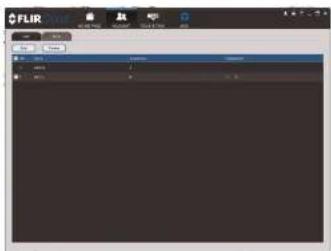
- Configure the following settings for the role:
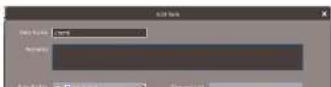
To delete a user account:
- Click X next to the role you would like to delete. Click OK to confirm.
17.15 General
The General menu is where you can configure application settings for the client software.
To access the General menu:
- Click and then click
17.15.1 Basic
The Basic menu contains general settings for the client software.
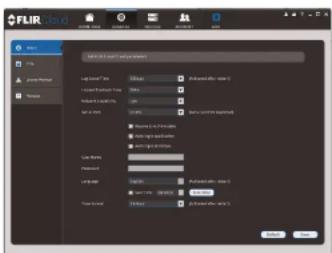
text_image
FLIR COLOR OK Cancel Show: Apply Preset Remove Add color to color Add color to color Add color to color Add color to color Add color to color Add color to color Add color to color Add color to color Add color to color Add color to color Add color to color Add color to color Add color to color Add color to color Add color to color Add color to color Add color to color Add color to color Add color to color Add color to color Add color to other colors Add color to other colors Add color to other colors Add color to other colors Add color to other colors Add color to other colors Add color to other colors Add color to other colors Add color to other colors Add color to other colors Add color to other colors Add color to other colors Add color to other colors Add color to other colors Add color to other colors Add color to other colors Add color to other colors Add color-to-color Add color-to-size Add color-to-size Add color-to-size Add color-to-size Add color-to-size Add color-to-size Add color-to-size Add color-to-size Add color-to-size Add color-to-size Add color-to-size Add color-to-size Add color-to-size Add color-to-size Add color-to-size Add color-to-size Add color-to-size Add color-to-size Add color-to-size Add color-to-size Add color-to-Color Add color-to-size Add color-to-size Add color-to-size Add color-to-size Add color-to-size Add color-to-size Add color-to-size Add color-to-size Add color-to-size Add color-to-size Add color-to-size Add color-to-size Add color-to-size Add color-to-size Add color-to-size Add color-to-size Add color-to-size Add color-to-size Add color-to-size Add color-to-age Add color-to-age Add color-to-age Add color-to-age Add color-to-age Add color-to-age Add color-to-age Add color-to-age Add color-to-age Add color-to-age Add color-to-age Add color-to-age Add color-to-age Add color-to-age Add color-to-age Add color-to-age Add color-to-age Add color-to-age Add color-to-age Add color-to-age Add color-to-ColorThe Basic menu contains the following settings:
- Log Saved Time: Select the number of days you would like the client to save log
- Instant Playback Time: Select the number of minutes the system will go back when you start an instant playback.
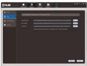
text_image
FLIR Name: 1234 System Name: FLIR Configuration: 1234 (system name) configuration panel Description: - System name: FLIR - System name: FLIR - System name: FLIR - System name: FLIR - System name: FLIR - System name: FLIR - System name: FLIR - System name: FLIR - System name: FLIR - System name: FLIR - System name: FLIR - System name: FLIR - System name: FLIR - System name: FLIR - System name: FLIR - Systems name: FLIR - Systems name: FLIR - Systems name: FLIR - Systems name: FLIR - Systems name: FLIR - Systems name: FLIR - Systems name: FLIR - Systems name: FLIR - Systems name: FLIR - Systems name: FLIR - Systems name: FLIR - Systems name: FLIR - Systems name: FLIR - Systems name: FLIR - Systems name: FLIRThe File menu contains the following options:
- Snapshot Path: Click Browse to select the default folder to save snapshots.
- Record Path: Click Browse to select the default folder to save video recordings.
- Config Path: Click Browse to select the folder where the client will save software con-
fig files.
Note
Click Save to save setting changes.
PC Users: You may need to run the client software as admin to save files to enable snapshot or video recording.
17.15.3 Alarm Prompt
The Alarm Prompt menu allows you to configure audio alerts. The client will play audio alerts when events occur. You can replace the default sounds with any .wav file.
Note
You must configure alarms in the Alarm CFG menu before the client will play alarm sounds.
- Video Loss: Select or preview the sound that will play for video loss alarms.
- Disk Full: Select or preview the sound that will play for disk full alarms.
- Disk Error: Select or preview the sound that will play for disk errors.
- External: Select or preview the sound that will play for external alarms (triggered by sensor devices, which may not be supported on all systems).
- E-map flashes when alarm occurs: If the camera has alarms enabled and is added to an e-map, a appears on the e-map when an event occurs.
Note Click Save to save changes.
17.15.4 Version
The Version menu shows you which version of the client software you are using. It is recommended to always run the latest version of the software from www.flirsecurity.com/pro.

text_image
FLIR Cloud Client Vulucor FLIR Cloud Client Service Name: 21.75 Address: 083-690-0000 Contact ID: 001-690-0000 URL: 001-690-0000Connecting to your System Using Smartphone or Tablet Apps
The system is compatible with iPhone, iPad and Android devices.
| Platform Supported Versions and Devices | App Name Get App From | ||
| iOS iPhone/iPad FLIR | CloudTM Apple App Store | ||
| Android Android FLIR | CloudTM Google Play Store | ||
See www.flirsecurity.com/pro for the latest list of supported apps and devices.
18.1 iPhone
FLIR Cloud™ is an iPhone app that allows you to remotely view your system.
18.1.1 Prerequisites
- Connect your system to your router using an Ethernet cable (included).
- Make sure to upgrade your system to the latest firmware version. You must have the latest firmware and mobile apps to connect to the system over the Internet
Note
For the latest list of supported apps and devices, visit www.flirsecurity.com/pro
Note
The first time it opens, the app will ask for permission to send push notifications and to access Photos. It will only send notifications if you enable motion-activated push notifications in the Push Config menu. It needs access to Photos to save snapshots and video clips to the local storage on your mobile device.
18.1.2 Connecting to your System on iPhone
- Download FLIR Cloud™ for free from the App Store.
- Tap on the FLIR Cloud™ icon() to start the app.
-
Tap = then + .
-
Configure the following:
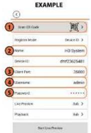
text_image
EXAMPLE 1 Scan EN Code Login Mode Name: HD System Service ID: dhf72602481 Client Port: 35090 Username: admin Password: ****** List Preview: Sub > Playback: Sub >4.1. Tap Scan QR Code and line up the QR code on the top of your system using the camera on your mobile device.

text_image
Device ID: xxxxxxxxxxOR
Under Device ID, manually enter the Device ID printed on the label.
4.2. Name: Choose a name for your system of your choice.
4.3. Client Port: Enter the Client Port (default: 35000).
4.4. User Name: Enter the system's User Name (default: admin).
4.5. Password: Enter the system's Password (default: 000000).
Live View Overview

text_image
Live Preview 1 2 3 4 5 6 7 8 9 10- Menu: Tap to bring up the Menu.
- Display Area: Double-tap to open a channel in full screen. Swipe left or right to select a different page of channels.
- Pages: Shows the number of pages available and highlights the currently selected page.
- Split: Select the split-screen layout.
- Snapshot: Tap to take a snapshot from the currently selected channel.
- Control Bar: Contains the following options. Swipe left or right to access more options.

- Tap to open PTZ controls.
PTZ Controls

text_image
Live Preview ① ② ③ ④ ⑤ PP2100 WECAMX- Live Display: Swipe to move the camera. Pinch to zoom in/out.
- Iris: Tap to show iris controls.
- Focus: Tap to show focus controls.
- Zoom: Tap to show zoom controls.
- PTZ/EPTZ: Tap to switch between PTZ and EPTZ mode. Use PTZ mode to control
PTZ cameras. Use EPTZ mode to activate digital zoom mode on non-PTZ cameras. - Goto preset: Tap to access preset controls. Then use the sliders to select a preset and then tap the checkmark to goto the preset.
Note
You must set presets for the camera using the system's local menus before you can use this feature.
Local Files Overview

text_image
Diagram showing four labeled surveillance camera setups with numbered annotations and vehicle images- Menu: Return to Menu.
- Files: Tap to open files.
- File Type: Tap the options to select video files or snapshots
- Options: Tap to delete or export files to your device's local storage.
Note Exported snapshots and video files are saved to the Photos app. Video files are saved to MP4 format.
18.1.6 Using Playback Mode on iPhone
You can access recorded video on your system using your iPhone.
Note
You must enable Sub Stream Recording to use playback mode on mobile devices.
To use Playback Mode:
- Use the on-screen controls to control playback.
Playback Controls
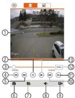
text_image
Front ① ② ③ ④ ⑤ ⑥ ⑦ ⑧ ⑨ ⑩ ⑪ ⑫ ⑬ ⑭ ⑮ ⑯ ⑰ ⑱ ⑲ ⑳ ㉑ ㉒ ㉓ ㉔ ㉕ ㉖ ㉗ ㉘ ㉙ ㉚ ㉛ ㉜ ㉝ ㉞ ㉟ ㉟A ㉟B ㉟C ㉟D ㉟E ㉟F ㉟G ㉟H ㉟I ㉟J ㉟K ㉟L ㉟M ㉟N ㉟O ㉟P ㉟Q ㉟R ㉟S ㉟T ㉟U ㉟V ㉟W ㉟X ㉟Y ㉟Z ㉟A ㉟B ㉟C ㉟D ㉟E ㉟F ㉟G ㉟H ㉟I ㉟J ㉟K ㉟L ㉟M ㉟N ㉟O ㉟P ㉟Q ㉟R ㉟S ㉟T ㉟U ㉟V ㉟W ㉟X ㉟Z ㉟A ㉟B ㉟C ㉟D ㉟E ㉟F ㉟G ㉟H ㉟I ㉟J ㉟K ㉟L ㉟M ㉟N ㉟O ㉟P ㉟Q ㉟R ㉟S ㉟T ㉟U ㉟V ㉟W ㉟Y ㉟Z4.1. Display Area: Double-tap to open in full-screen.
4.2. Play/pause.
4.3. Time Bar: Tap inside the bar to fast forward or rewind.
4.4. Previous: Select previous video file.
4.5. Next: Select next video file.
4.6. Snapshot: Tap to take a snapshot from the selected camera.
4.7. Stop All: Stop playback on all channels.
4.8. Not supported.
4.9. Manual Record: Tap to start/stop recording to your mobile device's local storage.
4.10. Fast.
4.11. Slow
4.12 Time Range: Tan to change the range of time shown in the time bar

text_image
F-UK Email F-UK Email 1.0000000000000000000000000000000000000000000000000000000000000000000000000000000000000000000000000000 F-UK Email 1.56289999999999999999999999999999999999999999999999999999999999999999999999999999999999999999999999999999 F-UK Email 1.562899999999999999999999999999999999999999999999999999999999999999 F-UK Email 1.562887343444444444444444444444444444444444444444444444444444444444444444444444 F-UK Email 1.56288733333333333333333333333333333333333333333333333333333333333333333333333Note
Your cameras must have motion detection activated to receive push notifications.
To enable Push Notifications:
- Tap ≡ to access the Menu, and then tap Push Config.
- Tap the system you would like to configure.

- Tap Motion Detect and then check each channel you would like to receive push notifications from.
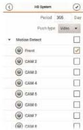
text_image
HD System Period 365 Day Push type Video Motion Detect Front CAM 2 CAM 3 CAM 4 CAM 5 CAM 6 CAM 7 CAM 8- Tap to save changes. You will now receive a notification when one of the selected cameras detect motion.
18.1.8 Using the Event List
The Event List menu shows a list of events that were sent to your device via push notifications.
Note
You must configure push notifications before you can use the Event List.
To access the Event List:
- Tap ≡ to access the Menu, and then tap Event List.
Event List Overview
18.1.9 Using Favorites
Favorites allows you to select a group of cameras as a favorite. You can then quickly bring up the group of cameras in Live View without having to individually select each camera.
To use Favorites:
- Tap ≡ to access the Menu, and then tap Favorites.
- Tap a group to configure an existing group.
Note

to create a new group and then enter a name for the new group.
- To add cameras to the group, tap.
- Select the cameras you would like to add to the group. Tap save changes.

text_image
Favorites HD Systems Front CAM 2 CAM 3 CAM 4 CAM 5 CAM 6 CAM 7 CAM 8Note
- Tap ★, and then tap to open the group.
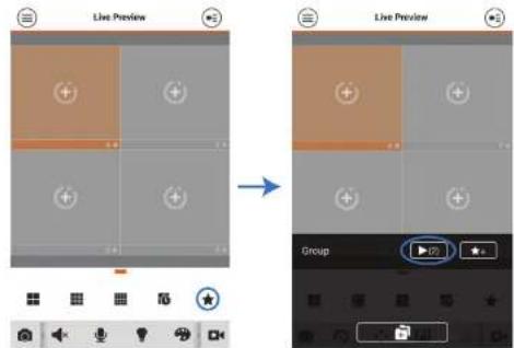
text_image
Live Preview Live Preview Group18.1.10 Using the E-Map
E-Map allows you to place cameras over a still image. For example, you can use the E-Map to create a virtual map of your cameras over a floor plan of your home or business.
To add an E-Map:
-
Tap ≡ to access the Menu, and then tap E-Map.
-
Tap ⊕.

- Press 📄 and select a camera. Drag the camera on the screen to place it on the map Repeat to add additional cameras.
text_image
Floor plan diagram with labeled rooms and location markers, including a small icon at the bottom.-
Click Choose a name for your E-Map and then tap OK. To open cameras from an E-Map:
-
Tap in Live View.
-
Select the E-Map in the Device List.
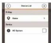
- Tap the camera or cameras to select and then tap Start Live Preview to open the cameras.

text_image
Stark Land Project18.1.11 Device Manager
You can use Device List to add, delete, or edit your systems.
To access Device Manager:
- Tap ≡ to access the Menu, and then tap Device Manager.
To edit a system:
- Tap the system in Device Manager. Tap
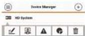
- Tap . Tap OK to confirm.

18.1.12 Adding Devices Using an IP or DDNS Address (Advanced)
The app can connect directly to a device via the IP address or DDNS address as an optional advanced connectivity method or for systems that do not support FLIR Cloud™.
Prerequisites:
- The device you are connecting to must be connected to the Internet.
- You must port forward the HTTP Port (default: 80) and Client port (35000) on your router to the device's local IP address.
- To ensure connectivity, it is highly recommended to register for a free DDNS domain to use with your system.
• For more information on port forwarding and DDNS, visit www.flirsecurity.com/pro.
To add a device using an IP or DDNS address:
-
Tap 📋 then +
-
Configure the following:
EXAMPLE
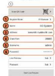
text_image
Login User Regulate Mode: 12/03/2016 Name: HO System Address: www.hodone.com Start Menu: 35000 Username: admin Password: ****** Live Preview: Sub > Playback: Sub > Add List Preschool2.1. Tap Register Mode and select IP/Domain.
2.2. Name: Choose a name for your system of your choice.
2.3. Address: Enter the IP address or DDNS address of your system.
2.4. Client Port: Enter the Client Port (default: 35000).
2.5. User Name: Enter the system's User Name (default: admin).
2.6. Password: Enter the system's Password (default: 000000).
-
Tap Start Live Preview. You will be prompted to change the system password.
-
Enter a new 6 character password and tap OK. This password will be used to log on to
your system from now on. - The app opens in Live View and streams video from your cameras.
18.2 iPad
FLIR Cloud™ is an iPad app that allows you to remotely view your system.
18.2.1 Prerequisites
- Connect your system to your router using an Ethernet cable (included).
- Make sure to upgrade your system to the latest firmware version. You must have the latest firmware and mobile apps to connect to the system over the Internet.
Note
For the latest list of supported apps and devices, visit www.flirsecurity.com/pro.
Note
The first time it opens, the app will ask for permission to send push notifications and to access Photos. It will only send notifications if you enable motion-activated push notifications in the Push Config menu. It needs access to Photos to save snapshots and video flips to the local storage on your mobile device.
18.2.2 Connecting to your system on an iPad
- Install FLIR Cloud™ for free from the App Store.
-
Tap on the FLIR Cloud™ icon(-) to start the app.
-
Tap

-
Tap Device Manager.
-
Tap Add.
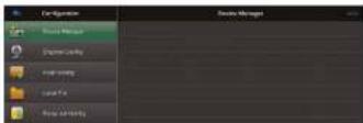
- Configure the following:
EXAMPLE
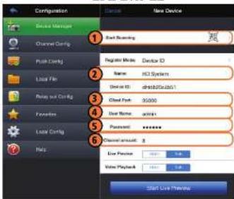
text_image
Configuration New Device 1 Start Screening 2 Register Mode: Device ID Name: HCL System Device ID: dshb02c0a01/1 3 Cloud Pack: 30000 4 User Name: admin 5 Password: ******** 6 Channel amount: 8 7 Low Price: 0.00 8 Value Playback: 0.00 Start Live Preview6.1. Tap Start Scanning and line up the QR code on the top of the system using the camera on your device.

text_image
Device ID: xxxxxxxxxxxxx
Under Device ID, manually enter the Device ID printed on the label.
6.2. Name: Choose a name for your system of your choice.
Live View Overview
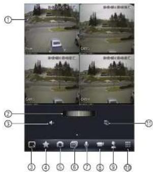
text_image
Camera navigation interface with labeled frames and adjustment knobs- Display area: Double-lap to open camera in full screen,
- Favorites: Slide to select favorites.
- Disconnect all: Disconnect all cameras.
- Add to favorites: Add the current view to favorites.
- Snapshot: Tap to take a snapshot from the currently selected channel.
Note
You can view or share snapshots using the Photos app.
- Change display view.
- Not supported.
- Manual record: Tap to start/stop manual recording from this channel.
- Not supported.
-
Open book
-
Slide the middle controls to the right to access PTZ controls.
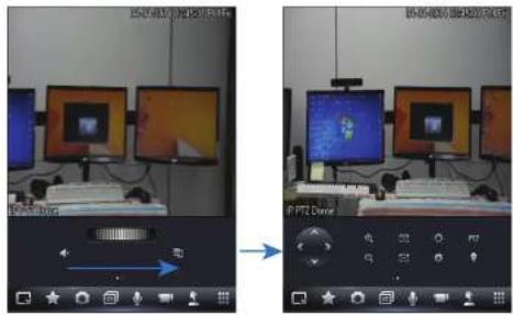
text_image
Screenshot of a video editing software interface showing two identical computer monitors with UI controls and a thermal map overlay.PTZ Controls
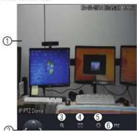
text_image
Screenshot of a computer setup with labeled monitor screens and keyboard, showing numbered UI elements.Note
You must enable Substream Recording to use playback mode on mobile devices.
To use Playback Mode:
1.
From Live View


- In Portrait Mode: Tap +, select the start time and end time for your search, and select the camera you would like to playback.
OR
In Landscape Mode: Select the start time and end time for your search, and drag the camera you would like to playback to the display area.

text_image
Screenshot of a surveillance camera interface with multiple video thumbnails and a traffic light overlay, showing vehicle detection status.- Use the playback controls.
Playback Controls

text_image
Front ① ② ③ ④ ⑤ ⑥ ⑦ ⑧ ⑨ ⑩ ⑪- Display area: Double-tap to open camera in full screen.
- Play/pause.
- Previous file.
- Disconnect: Disconnect the currently selected camera.
- Not supported.
- Snapshot: Tap to take a snapshot from the currently selected camera.
- Change display view.
- Menu.
- Next file.
- Time range: Tap to change the range of time shown in the time bar.
- Time Bar: Tap inside the bar to fast forward or rewind.
Note
Playback controls are only shown in postmit mode.
- Tap a video file to open it.
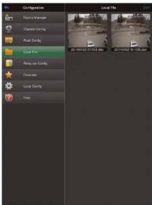
text_image
Configuration Local File Dissuca Manager Clearance Corning Post Corning Local File Reddy and Corning Fireworks Local Corning ShapeTo delete videos:
-
Tap Edit.
-
Select the videos you would like to delete and tap
18.2.7 Enabling Push Notifications
You can have the app send push notifications to the notifications area on your device when one of your cameras detects motion. Once you have received a push notification, you can

text_image
FUP Cloud FUP Cloud H:\System Channel 2 Volume Cloud 2014-03-29 16:18:18 FUP Cloud H:\System Channel 1 Volume Cloud 2014-03-29 16:18:08 FUP Cloud H:\system Channel 1 Volume Cloud 2014-03-29 16:15:42Note
Your cameras must have motion detection activated to receive push notifications.
To enable Push Notifications:
- From live view, tap then
- Tap Push Config.
- Tap the slider for the system you would like to configure.
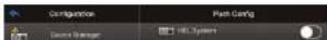
- Tap Motion Detect then check each channel you would like to receive push notifications from.

text_image
Configuration Device Manager Electronic Comps File Edit Layer File Recovery Comps Properties Local Comps Help File Edit HD System Period: 50 fps Type: ProPhase Video editor Flow CAM 2 CAM 3 CAM 4 CAM 5 CAM 6 CAM 7 CAM 8 1. User Info- Under Type, select Playback to attach a video file with each push notification. Or, select Picture to attach a still image of the camera that detected motion.
- Tap OK to save change. Whenever the selected cameras detect motion, you will receive a notification.
18.2.8 Using the Event List
The Event List menu shows a list of events that were sent to your device via push notifications.
18.2.9 Using Favorites
Favorites allows you to select a group of cameras as a favorite. You can then quickly bring up the group of cameras in Live View without having to individually select each camera.
To create favorites:
-
In Live View, lap to save the cameras that are currently open as a favorite.
-
Enter a name for the favorite and tap OK.
To open favorites in Live View:
• In Live View, slide the dial to cycle through favorites.
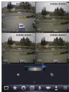
text_image
Screenshot of a surveillance camera interface showing four sequential frames with Chinese text labels and a blue arrow indicating navigation.To edit favorites:
-
From live view, tap then
-
Tao Favorites.
18.2.10 Using the E-Map
E-Map allows you to place cameras over a still image. For example, you can use the E-Map to create a virtual map of your cameras over a floor plan of your home or business.
To add an E-Map:
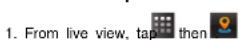
- Tap Add.

- Select a .jpg image file on your mobile device.

text_image
Preview Current Post- To edit the E-map:

text_image
Untitled ① ② ③4.1. Select Image: Select different image file to use for your E-Map.
4.2. Add Camera: Tap + to select cameras to add to your E-Map. Then drag the camera to place it on the E-Map.
4.3. Delete E-Map.
- When you are finished editing the E-Map, tap Save and enter a name for the E-Map to save changes.
To open cameras using the E-Map:
-
In live view, tap + on an empty display window and select the E-Map.
-
Tap a camera from the E-map to open.
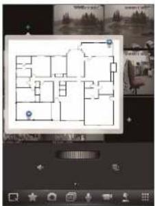
text_image
Screenshot of a mobile home design interface showing a floor plan with labeled rooms and navigation controls18.2.11 Using the Device Manager
Device Manager allows you to manage your systems.
To access Device Manager:
- From live view, tap then
- Tap Device Manager.
To delete a system: - Tap the system to select it.
- Tap ☐. Tap Yes to confirm.

- You must port forward the HTTP Port (default: 80) and Client port (default: 35000) on your router to the device's local IP address.
- To ensure connectivity, it is highly recommended to register for a free DDNS domain to use with your system.
- For more information on port forwarding and DDNS, visit www.flirsecurity.com/pro.
To add a device using an IP or DDNS address:
-
Install FLIR Cloud™ for free from the App Store.
-
Tap on the FLIR Cloud™ icon() to start the app.
- Tap then
- Tap Device Manager.
- Tap Add.
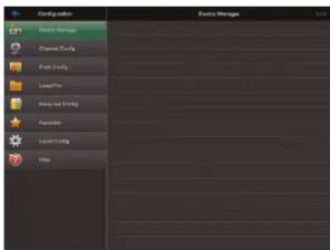
text_image
Configuration Edit Manager Delete Manager Channel Control Push Control Level Pro Using Just Binding Favorites Locking Help- Configure the following:
EXAMPLE
text_image
Configuration Device Manager Channel Control Back Control Local File Binary and Control Patterns Local Control Phone New Device Back Screening Register Media: IP-Domain Name: HD-System Address: 8120731.9745126.97.97 Class Port: 00000 Show Names: admin Password: ******** Channel Amount: g Live Preview Add Playback Save Lock Presets Start Lock Presets6.1. Tap Register Mode and select IP/Domain. Then tap New Device to return to the New Device screen.
6.2. Name: Choose a name for your system of your choice.
6.3. Address: Enter the DDNS or IP address of your device.
6.4. Client Port: Enter the Client Port (default: 35000).
6.5. User Name: Enter the system's User Name (default: admin).
6.6. Password: Enter the system's Password (default: 000000)
6.7. Channel Amount: Enter the number of channels your system has.
-
Tap Start Live Preview. You will be prompted to change the system password.
-
Enter a new 6 character password and tap OK. This password will be used to log on to your system from now on.
-
The app opens in Live View and streams video from all connected cameras.
18.3 Android
FLIR Cloud™ allows you to remotely view your system on Android devices.
18.3.1 Prerequisites
- Connect your system to your router using an Ethernet cable (included).
- Make sure to upgrade your system to the latest firmware version. You must have the latest firmware and mobile apps to connect to the system over the Internet.
Note
For the latest list of supported apps and devices, visit www.flirsecurity.com/pro.
18.3.2 Connecting to your System on Android
- Download FLIR Cloud™ for free from the Google Play Store.
-
Tap on the FLIR Cloud™ icon (-) to start the app.
-
Tap = then +

Live Preview


Device List

- Configure the following:
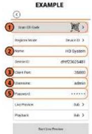
text_image
EXAMPLE 1 Scan UK Code Register Mode Name: HD System Device ID: dhf726025481 Client Port: 35000 Username: Admin Password: ****** List Preview: 566 > Playback: 566 > Next Live Preview4.1. Tap Scan QR Code and line up the QR code on the top of your system using the camera on your mobile device.
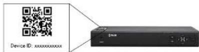
text_image
Device ID: xxxxxxxxxxOR
Under Device ID, manually enter the Device ID printed on the label.
4.2. Name: Choose a name for your system of your choice.
4.3. Client Port: Enter the Client Port (default: 35000).
4.4. User Name: Enter the system's User Name (default: admin).
4.5. Password: Enter the system's Password (default: 000000).
Live View Overview
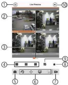
text_image
Live Preview 10 2 3 4 5 6 7 8 9 ① ② ③ ④ ⑤ ⑥ ⑦- Menu: Tap to bring up the Menu.
- Display Area: Double-tap to open a channel in full screen. Swipe left or right to select a different page of channels.
- Pages: Shows the number of pages available and highlights the currently selected page.
- Split: Select the split-screen layout.
- Snapshot: Tap to take a snapshot from the currently selected channel.
- Control Bar: Contains the following options. Swipe left or right to access more options.
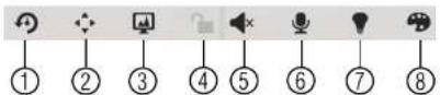
- Tap to open PTZ controls.
PTZ Controls
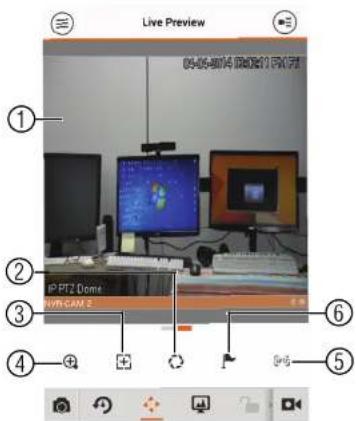
text_image
Live Preview 04-06-014 DR211 PKT IP PTZ Dome NVR-CAM 2- Live Display: Swipe to move the camera. Pinch to zoom in/out.
- Iris: Tap to show iris controls.
- Focus: Tap to show focus controls.
- Zoom: Tap to show zoom controls.
- PTZ/EPTZ: Tap to switch between PTZ and EPTZ mode. Use PTZ mode to control PTZ cameras. Use EPTZ mode to activate digital zoom mode on non-PTZ cameras.

text_image
Diagram showing four labeled surveillance camera setups with numbered annotations and vehicle images- Menu: Return to Menu.
- Files: Tap to open files.
- File Type: Tap the options to select video files or snapshots.
- Options: Tap to share, delete, or export files to your device's local storage.
Note
Exported video files are saved to MP4 format in the folder /snapshot/mp4/, which you can access by connecting your Android device to a computer using a USB cable.
18.3.6 Using Playback Mode on Android
You can access recorded video on your system using your Android.
Note
You must enable Sub Stream Recording to use playback mode on mobile devices. For details on enabling Sub Stream Recording, see 11.3 Setting up Scheduled or Manual Recording, page 25.
To use Playback Mode:

- Use the on-screen controls to control playback.
Playback Controls

text_image
Front 13 12 11 10 8 7 6 5 4 3 2 1 Front Control buttons Control buttons Control buttons Control buttons Control buttons Control buttons Control buttons Control buttons Control buttons Control buttons Control buttons Control buttons Control buttons Control buttons Control buttons Control buttons Control buttons Control buttons Control buttons Control buttons Control buttons Control buttons Control buttons Control buttons Control buttons Control buttons Control buttons Control buttons Control buttons Control buttons Control buttons Control buttons Control buttons Control buttons4.1. Display Area: Double-tap to open in full-screen.
4.2. Play/pause.
4.3. Time Bar: Tap inside the bar to fast forward or rewind.
4.4. Previous: Select previous video file.
4.5. Next: Select next video file.
4.6. Snapshot: Tap to take a snapshot from the selected camera.
4.7. Stop All: Stop playback on all channels.
4.8. Not supported.
4.9. Manual Record: Tap to start/stop recording to your mobile device's local storage.
4.10. Fast.
4.11. Slow
4.12 Time Range: Tan to change the range of time shown in the time bar
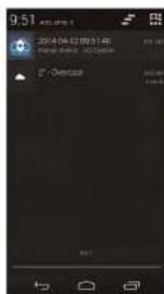
text_image
9.51 2014-04-21 09:31 48 675000Note
Your cameras must have motion detection activated to receive push notifications.
To enable Push Notifications:
- Tap ≡ to access the Menu, and then tap Push Config.
- Tap the system you would like to configure.

- Tap Motion Detect and then check each channel you would like to receive push notifications from.
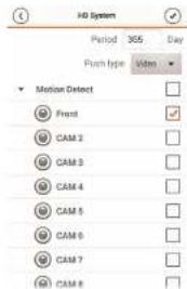
text_image
HD System Period 365 Day Push type Video Motion Detect Front CAM 2 CAM 3 CAM 4 CAM 5 CAM 6 CAM 7 CAM 8- Under Push type, select Video to attach a video clip to each push notification. Or, select Image to attach an image to each push notification.
- Tap √ to save changes. You will now receive a notification when one of the selected cameras detect motion.
18.3.8 Using the Event List
The Event List menu shows a list of events that were sent to your device via push notifications.
Note
You must configure push notifications before you can use the Event List.
To access the Event List:
• Tan ≡ to access the Menu and then tan Event List
- Tap ≡ to access the Menu, and then tap Favorites.
- Tap a group to configure an existing group.
Note
Tap to create a new group and then enter a name for the new group.
- To add cameras to the group, tap.

- Select the cameras you would like to add to the group. Tap to save changes.
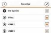
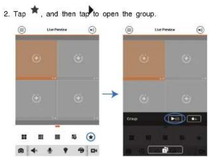
text_image
2. Tap ★, and then tap to open the group.18.3.10 Using the E-Map
E-Map allows you to place cameras over a still image. For example, you can use the E-Map to create a virtual map of your cameras over a floor plan of your home or business.
To add an E-Map:
- Tap ≡ to access the Menu, and then tap E-Map.
- Tap ⊕.
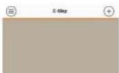
- Press 📄 and select a camera. Drag the camera on the screen to place it on the map Repeat to add additional cameras.

text_image
Floor plan diagram with labeled rooms and location markers, including a small icon at the bottom.-
Click Choose a name for your E-Map and then tap OK. To open cameras from an E-Map:
-
Tap in Live View.
-
Select the E-Map in the Device List.

- Tap the camera or cameras to select and then tap Start Live Preview to open the cameras.
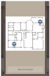
text_image
Stark Land Project18.3.11 Device Manager
You can use Device List to add, delete, or edit your systems.
To access Device Manager:
- Tap ≡ to access the Menu, and then tap Device Manager.
To edit a system:
- Tap the system in Device Manager. Tap

- Tap . Tap OK to confirm.

18.3.12 Adding Devices Using an IP or DDNS Address (Advanced)
The app can connect directly to a device via the IP address or DDNS address as an optional advanced connectivity method or for systems that do not support FLIR Cloud™.
Prerequisites:
- The device you are connecting to must be connected to the Internet.
- You must port forward the HTTP Port (default: 80) and Client port (default: 35000) on your router to the device's local IP address.
- To ensure connectivity, it is highly recommended to register for a free DDNS domain to use with your system.
• For more information on port forwarding and DDNS, visit www.flirsecurity.com/pro.
To add a device using an IP or DDNS address:
-
Tap 📋 then +
-
Configure the following:
EXAMPLE

text_image
Login User Regulate Mode: 12/03/2016 Name: HO System Address: www.hodone.com Start Menu: 35000 Username: admin Password: ****** Live Password: Sub > Playback: Sub > Exit Live Preview2.1. Tap Register Mode and select IP/Domain.
2.2. Name: Choose a name for your system of your choice.
2.3. Address: Enter the IP address or DDNS address of your device.
2.4. Client Port: Enter the Client Port (default: 35000).
2.5. User Name: Enter the system's User Name (default: admin).
2.6. Password: Enter the system's Password (default: 000000).
-
Tap Start Live Preview. You will be prompted to change the system password.
-
Enter a new 6 character password and tap OK. This password will be used to log on to
your system from now on.

Remote Viewing On Internet Explorer
You can also view your system remotely using Internet Explorer (version 8 or later required). In order to view your system on Internet Explorer over the Internet, you must set up DDNS and port forwarding.
Note
Remote viewing is only compatible with Internet Explorer. Mozilla Firefox, Opera, Safari, and other browsers are not supported.
19.1 Prerequisites
- The HTTP Port (default: 80) and Client Port (default: 35000) must be port forwarded to your router.
- You must create a DDNS account, and have the DDNS settings configured in your NVR. For details, 20 DDNS Setup (Advanced), page 154.
- The NVR must have internet access.
To view your system using Internet Explorer:
- Open Internet Explorer. It is recommended to select Run as Administrator when opening Internet Explorer to ensure full functionality.
- In the address bar, enter your system's IP address or DDNS address followed by the HTTP Port (default: 80). For example, http://192.168.1.1:80 or http://tomsmith.myddns-flir.com:80.
Note
You MUST include http:// in order to access your system.
- An attention bar appears at the top or bottom of the screen to prompt you to install ActiveX plugins, click Install or Allow and follow the prompts to install the plugins.
- Enter the system user name and password (by default admin / 000000).
- Select LAN to connect using the main (high quality) stream. Select WAN to use the substream to conserve bandwidth and for improved performance when connecting over the Internet.
-
Click Login to log in.
-
Double click on cameras in the camera list to open them in live view.

text_image
Screenshot of a software interface with four grid panels and tool panels, showing icons and status bar in Chinese.19.1.1 IE Live Display Overview
Note
Some options are not available in WAN mode.

text_image
Fltir ① ② ③ ④ ⑤ ⑥3. Live View Controls:
- Start Talk: Click to enable 2-way audio.
- Instant Record: Not supported.
- Local Play: Open recorded or back up video files (.dav) saved on the local computer.
4. Live View Toolbar:
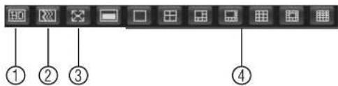
text_image
Screenshot of a software toolbar with labeled icons and numbered labels ① to ④4.1. Select image quality.
4.2. Fluency/latency.
4.3. Full-screen.
4.4. Select display view.
5. PTZ Controls.
- Color Settings: Use the sliders to adjust the brightness, contrast, saturation, and hue for the selected camera.
19.1.2 Using Search Mode in IE (Playback)
You can access recorded video from your NVR using the Internet Explorer client.
To access recorded video from your NVR:
- Click Search.
- Perform the following to start playback:

DDNS Setup (Advanced)
Free DDNS service is available as an optional connectivity method to connect to your system over the Internet.
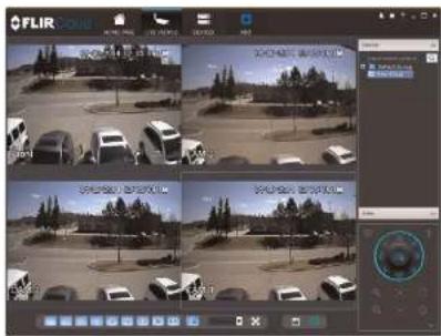
text_image
FLIR FLIR FLIR FLIR FLIR FLIR FLIR FLIR FLIR FLIR FLIR FLIR FLIR FLIR FLIR FLIR FLIR FLIR FLIR FLIR FLIR FLIR FLIR FLIR FLIR FLIR FLIR FLIR FLIR FLIR FLIR FLIR FLIR FLIR FF FF FF FF FF FF FF FF FF FF FF FF FF FF FF FF FF FF FF FF FF FF FF FF FF FF FF FF FF FF FF FF FF FF FF FF FF FF FF FF FF FF FF FF FF FF FF FF FF FF F10000000000000000000000000000000000000000000000000000000000000000000000000000000000000000000000000000Note
Except where noted, the instructions in this section are the same on PC or Mac.
20.1 Accessing your System within a Local Network (LAN)
You can connect to your system through using the Client Software through the local area network (LAN). It is recommended to confirm connectivity over a local network before setting up your system for DDNS connectivity.
Note
To complete the steps below, your computer must be on the same network as your system.
20.1.1 Step 1 of 3: Connect your System to Your Router
20.1.2 Step 2 of 3: Obtain the System's Local IP Address
- Right-click to open the Quick Menu and click Info. Enter the system user name (default: admin) and password (default: 000000).
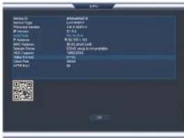
text_image
Service ID Baidu Phone Baidu Phone Baidu Phone Baidu Phone A Google Baidu Google Baidu Google Baidu Google Baidu Google Baidu Google Baidu Google Baidu Google Baidu Google Baidu Google Baidu Google Baidu Google Baidu Google Baidu Google Baidu Google Baidu Google Baidu Google Baidu Google Baidu Google Baidu Google Baidu Google Baidu Google Baidu Google Baidu Google Baidu Google Baidu Google B Institute- Write down the IP Address of the system.
• A local IP looks something like this: 192.168.5.118.
20.1.3 Step 3 of 3: Connect to the System's Local IP Address
Follow the steps below to confirm connectivity over a local network on a PC or Mac.
To connect using the system's local IP address:
- Download and install the client software.
• PC Users: Download and install the Client Software for PC from www.flirsecurity.com/pro.
- Mac Users: Download and install the Client Software for Mac from www.flirsecurity.com/pro. Double click to extract the software. Drag the software to Applications.
-
Once installation is finished, double-click the FLIR Cloud™ Client icon)(from the desktop or Applications list.
-
The client scans your LAN for connected systems. Check your system (a) and click Add (b).

text_image
FLIR Group FLIR Group FLIR Group FLIR Group FLIR Group FLIR Group FLIR Group FLIR Group FLIR Group FLIR Group FLIR Group FLIR Group FLIR Group FLIR Group FLIR Group FLIR Group FLIR Group FLIR Group FLIR Group FLIR Group FLIR Group-
Enter the password for your system (default: 000000) and click OK.
-
If this is the first time you are connecting, you will be prompted to change the system password.

- Enter a new 6 character password and click OK. This password will be used to connect to your system from now on.

- Click and drag Default Group to the display window to open your cameras in live view.

text_image
FLIR cloud FLIR cloudResult
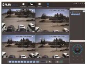
text_image
Screenshot of a video editing software interface showing a grid of surveillance feeds with vehicle images and a control panel.20.2 DDNS Setup—Access your System Remotely over the Internet
Note
If the above ports are not forwarded on your router, you will not be able to access your system remotely.
20.2.2 Step 2 of 4: Create a DDNS Account
To setup your free FLIR DDNS account:
- In your browser, go to http://ddns.myddns-flir.com and click Create Account.
FLIR
Login
▶ Create Account
Lost Password
- Complete the Account Information fields with your personal information. Complete the Warranty Information with your purchase details (optional).

text_image
Credit Card Account Account Information Email: email@citbitc.com Password: ******** Password account: ******** First name: Type Last name: Smith Origin: Origin Country: Canada Transmit: Eastern Standard Term (ET) By clicking on "Create New Account" you create the Terms of Account.- Complete the System Information fields:
- Product License: Select your product model from the Product License drop down menu (i.e. DNR400 Series).
-
• To find the MAC address, right-click to open the Quick Menu and click Info.

text_image
Device 0 Device Type: 123.0000 Device Name: LTR-00001 Device Size: 5.0 Device Count: 16.0 Device Address: 400-841-187 Device Name: 720-941-188 Device Type: 720-941-188 Device Name: 950-020 Device Type: 950-020 Device Size: 16 Device Count: 16- URL Request: Choose a URL for your DDNS connection (i.e. your name, your company or business name, or anything of your choice).

text_image
System Information Product License DNR200 - Product Code> -- Click Create New Account.
- Your account information will be sent to you at the email Address you used in Step 2. You will need this information for remote access to your system. Record your information below:
| Domain name/URL Request: | |
| URL Request: |
2.
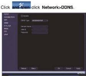
text_image
Click and then click Network>DDNS. Network SNCS Type: WISHERS/MSR Network Name: Class I: Password: Default Next OK Cancel Apply- Check Enable.
- Under Domain Name, enter the Domain Name/URL Request your received in the email after registering for DDNS.
- Under User Name, enter your DDNS User Name.
- Under Password, enter your DDNS Device password.
- Click OK to save your settings.
Note
Please allow 10–15 minutes for the DDNS servers to update with your new DDNS address before attempting to connect.
20.2.4 Step 4 of 4: Connect to the System's DDNS Address
Note
Please allow 10–15 minutes for the DDNS servers to update with your new DDNS address before attempting to connect.
To connect using the system's DDNS address:
- Log into the Client Software using the Client Software user name (default: admin) and password (default: admin) and then click Login.

text_image
FLIR Cloud User NAME: admin Password: ****** Belarusian Password { Login } { Fail }- Click Add Device.
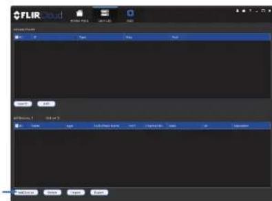
text_image
FLIR audio 文件(F) 100% 200% 300% 400% 500% 600% 700% 800% 900% 1000% 1100% 1200% 1300% 1400% 1500% 1600% 1700% 1800% 1900% 2000% 2100% 2200% 2300% 2400% 2500% 2600% 2700% 2800% 2900% 3000% 3100% 3200% 3300% 3400% 3500% 3600% 3700% 3800% 3900% 4000% 4100% 4200% 4300% 4400% 4500% 4600% 4700% 4800% 4900% 5000% 5100% 5200% 5300% 5400% 5500% 5600% 5700% 5800% 5900% 6000% 6100% 6200% 6300% 6400% 6500% 6600% 6700% 6800% 6900% 7000% 7100% 7200% 7300% 7400% 7500% 7600% 7700% 7800% 7900% 8000% 8100% 8200% 8300% 8400% 8500% 8600% 8700% 8800% 8900% 9000% 9100% 9200% 9300% 9400% 9500% 9600% 9700% 9800% 9900% 100- Enter the following:
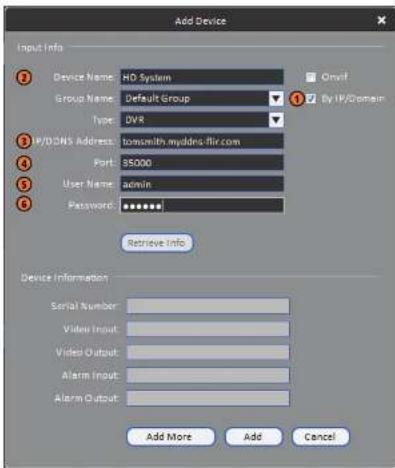
text_image
Add Device Input Info Device Name: HD System Group Name: Default Group Type: DVR P/D/DNS Address: tosnwith.myddns.flir.com Port: 35000 User Name: admin Password: ****** Retrieve Info Device Information Serial Number: Video Input: Video Output: Alarm Input: Alarm Output: Add More Add Cancel5.1. Check By IP/Domain to add a system using the DDNS address.
5.2. Device Name: Choose a name for your system of your choice.
5.3. IP/DDNS Address: Enter the Domain Name/URL Request you received in the email when you registered for DDNS followed by .myddns-fllr.com.
Note
- Enter a new 6 character password and click OK. This password will be used to connect to your system from now on.
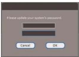
text_image
Please update your system's password. Cancel OK- Click


- Click and drag Default Group to the display window to open your cameras in live view.
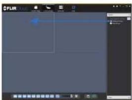
Congratulations! You can now connect over the Internet to view and playback video on your computer.
Connecting a PTZ Camera (DNR400 Series)
You can connect PTZ cameras (not included) to the system. FLIR IP PTZ cameras can accept PTZ commands directly through the Ethernet cable or you can connect PTZ cameras to the RS485 connectors on the back of the system.
To connect a FLIR PTZ camera to the system:
- Connect the camera Ethernet cable to one of the PoE Ports on the system. OR
Connect the camera to the local network (LAN) and then add it to the NVR. See 6.11
Connecting Cameras to the Local Area Network (LAN), page 12 for details.
-
Right-click and click Main Menu. Enter the system user name (default: admin) and password (default: 000000) if prompted.
-
Click >Setting>Pan/Tilt/Zoom.
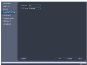
text_image
DISPLAY TITLE FORMATISTCOM ACCOUNT CONFIGURE OFFSET UPDATE Default OK Cancel Apply- Under Channel, select the channel your PTZ camera is connected to.
- Under PTZ Type, select Remote. This allows the system to control the PTZ functions over the Ethernet cable.
- Click OK. You can now control your PTZ camera using the system.
To connect a PTZ camera to the system via RS485:
- Connect RS485 cables from the camera to the A (+) and B (-) ports on the NVR.

text_image
ETHERNET RS485: A (TX+) B (TX-)- Right-click and click Main Menu. Enter the system user name (default: admin) and password (default: 000000) if prompted.
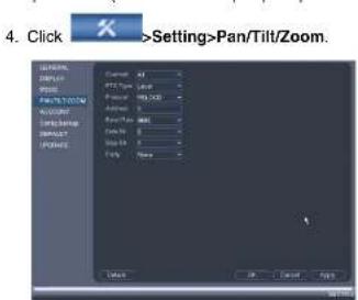
text_image
4. Click >Setting>Pan/Tilt/Zoom. UPPER SIZE BRIN PACTS/TOTAL R/COUNT SPRINGING SPRING Current: 0% FTT Type: 125 Color: RGB Distance: 0% Size: 0% Spec: None OK Cancel Apply- Right-click and click PTZ. Enter the system user name and password if prompted. The PTZ menu opens.
- Use the on-screen PTZ controls to control the camera.
PTZ Controls

text_image
Speed 5 Zoom Focus Iris- Direction keys: Click to pan and tilt the camera. Click SIT to stop the current action.
-
Mouse PTZ: Click to activate mouse PTZ mode. In mouse PTZ mode:
-
Click and drag to move the camera,
-
Use the scroll wheel to zoom in and out.
• Right-click to exit and return to normal PTZ controls. -
Zoom/Focus/Iris: Click +/- to adjust the zoom, focus, and iris.
- Advanced controls: Click to open advanced PTZ controls.
- Speed: Enter the PTZ speed.
21.2 Advanced PTZ Controls
Advanced PTZ controls can be used to save camera positions and cycle through various positions, and automate camera actions.
To open advanced PTZ controls:
- Click the arrow in the PTZ control window to open advanced controls.

- PTZ camera menu: Click to open the camera's OSD menu. This may not be supported on all camera models.
- Preset: Click to call the selected preset.
- Autopan: Click to start autopan. During autopan, the camera will continuously pan 360".
- Tour: Click to run the selected tour.
- Flip: Click to flip the camera 180".
- Pattern: Click to run the selected pattern.
- Reset: Click to move the camera to the home position.
- Auto scan: Click to run the selected autoscan.
- Aux: Click to open the aux menu, where you can set up Presets, Tours, Patterns, and Auto Scans.
21.2.1 Presets
Presets will save a camera position for quick retrieval.
To add presets:
-
Click to open the aux menu.
-
Click the Preset tab.

text_image
PANTILT/ZOOM Preset Tour Pattern Border Preset: 1 Set Set Preset- Enter the number of the preset you want to create under Preset.
-
Move the camera to the desired position and click Set.
-
Under Patrol No., select the tour you would like to configure.
- Under Preset, select a preset you would like to add to the tour.
- Click Add Preset.
- Repeat steps 4 and 5 to add additional presets to the tour.
Note
Click Del Tour to clear all presets from a tour.
To run a tour:
- Under No., select the number of the tour you would like to go to and click
21.2.3 Pattern
Patterns automatically cycle the camera between two positions.
To create a pattern:
- Click 📋 to open the aux menu.
- Click the Pattern tab.
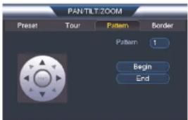
text_image
PANTILT:ZOOM Preset Tour Pattern Border Pattern 1 Begin End- Under Pattern, enter the pattern you would like to configure.
- Move the camera into the desired start position and click Begin.
-
Move the camera into the desired end position and click End.
-
Move the camera into the desired left position and click Left.
- Move the camera into the desired right position and click Right.
To run an auto scan:
- Click

DNR400 Series Hard Drive Installation
The system comes with a pre-installed 3.5" SATA hard drive. You can install up to two hard drives up to a maximum size of 4TB each.
22.1 Installing a Hard Drive

CAUTION
Make sure that the system is OFF and the power cable is disconnected before removing/installing the hard drive.
To install the hard drive:
- Insert hard drive screws (4x) on the hard drive and tighten them half way.

- Power off the system, and unplug all cabling from the system.
- Remove the rear panel screws (4x). Remove the cover.
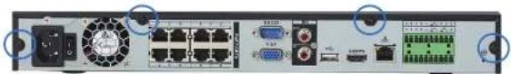
natural_image
Front view of a network equipment rack with ports, switches, and connectors (no visible text or labels)- Place the hard drive over one of the sets of screw slots on the bottom of the system and then slide the hard drive into place. The SATA connectors on the hard drive should face the center of the unit.
- Turn the system over carefully. Tighten the hard drive screws (4x) to secure the hard drive.

natural_image
Back view of a silver computer drive with multiple ports and mounting holes (no visible text or labels)
CAUTION
Hold the hard drive in place when turning the system over to prevent damage to the system.
- Connect the SATA power and data cable to the hard drive.
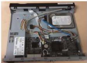
natural_image
Interior view of a laptop showing internal circuit board and wiring (no visible text or symbols)- Turn the system over and loosen the hard drive screws (4x), but do not remove them.
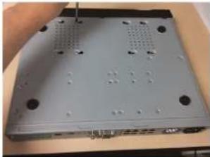
natural_image
Back view of a silver computer drive chassis with ventilation slots and ports (no visible text or labels)- Disconnect the SATA power and data cable from the hard drive.

natural_image
Laptop interior showing internal circuit board and wiring (no visible text or labels)- Carefully turn the system over. Slide the hard drive and then lift it out of the system.

To format the hard drive:
- From the Main Menu, click ✕ and then click Storage>HDD Manager.

text_image
HKEYMAN257 REGIST HKEYMAN257 REGIST HKEYMAN257 REGIST HKEYMAN257 REGIST HKEYMAN257 REGIST HKEYMAN257 REGIST HKEYMAN257 REGIST HKEYMAN257 REGIST HKEYMAN257 REGIST HKEYMAN257 REGIST HKEYMAN257 REGIST HKEYMAN257 REGIST- Select the hard dive you would like to format and then click Format. Click OK to confirm.
- Click OK to save changes. The system will restart to complete the formatting process.
Troubleshooting
When a malfunction occurs, it may not be serious and can be corrected easily. The following describes the most common problems and solutions. Please refer to the following before calling FLIR Technical Support:
| Error | Possible Causes Solutions | |
| System is not receiving power, or is not powering up. | Cable from power adapter is loose or is unplugged. | Confirm that all cables are connected correctly.Confirm that the power adapter is securely connected to the back of the unit. |
| Power switch is set to OFF (●) position. | Confirm that the power switch is in the ON (I) position. | |
| Cables are connected, but system is not receiving sufficient power. | Confirm that the system is powered on (LED indicators on the front should be ON).If the unit is connected through a power bar or surge protector, try bypassing the bar and connecting the power directly to the wall outlet.Confirm that there is power at the outlet:Connect the power cable to another outlet.Test the outlet with another device (such as a lamp or phone charger). | |
| Remote control is not detected by the system. | Battery in the remote control is drained.There are no batteries in the remote control. | Install two fresh AAA alkaline batteries in the remote control. |
| Hard drive is not detected by the system. | Hard drive cables are loose or not properly connected. | Remove the housing and check that hard drive cables. |
Troubleshooting23
| Error Possible Causes Solutions | ||
| There is no picture on monitor/TV after connecting it to the system. | Monitor/TV not detected by system. | Power off the monitor/TV and system. Power on the monitor/TV, and then power on the system. |
| Input channel for system not selected on monitor/TV. | On the monitor/TV, select the input channel the system is connected to. | |
| Video cable is loose or has become disconnected. | Check the video cable connection to the system and monitor/TV. | |
| Mouse not detected by system. | Mouse cable is not firmly connected to the system. Mouse is not connected to the system. | Firmly connect the mouse cable to one of the USB ports. |
| System needs to be reset | Power off the system (disconnect power cable). Firmly connect a USB mouse to one of the USB ports. Reconnect the power cable to the DC 12V port on the rear panel. | |
| There is no picture on selected channels / camera picture is not being displayed. | Camera cables are loose or have become disconnected. | Check the camera video cable and connections.Disconnect and reconnect the cable at the system and at the camera.Try moving the camera to another channel or use another cable. |
| The image on the system appears, but does not have sound. | Audio is not supported by this system. | |
| The system beeps at startup. | The been at startup is normal. |
DNR400 Series System Specifications
24.1 System
| Operating System | Embedded LINUX |
| Pentaplex | Simultaneous View, Record, Playback, Backup, and Remote Monitoring |
| Number of Channels 8/16 Channels |
24.2 Inputs/Outputs
| Video IN 8/16 ch: 8 PoE Video Input | |
| Video OUT No | |
| VGA OUT Yes | |
| HDMI Yes | |
| Audio IN | 1 Line IN (RCA) for 2-way audio |
| Audio OUT 1 Line OUT (RCA) for 2-way audio | |
| USB Port 1 at the back, 1 at the front | |
| Alarm IN 4 Alarm IN | |
| Alarm OUT 2 Alarm OUT | |
| Video Output Resolution | 1920x1060, 1280x1024, 1260x720, 1024x766 |
| PTZ Control RS-485, supports Pelco-D and Pelco-P | |
24.3 Display
| Display Split 8 ch: 1/4/8/9 | 16 ch: 1/4/8/9/16 |
| Live Display Speed 8 ch: 240FPS NTSC, 200FPS PAL | 16 ch: 400FPS NTSC, 400FPS PAL |
| OSD | Camera Title, Time, Camera Lock, Motion Delec lion, Recording Status |
| System Navigation | USB mouse |
| Record Rate NTSC | 8 ch: 240FPS @ 720P / 1080P / 3MP / 5MP16 ch: 480FPS @ 720P / 1080P / 3MP / 5MPPAL8 ch: 200FPS @ 720P / 1080P / 3MP / 5MP16 ch: 400FPS @ 720P / 1080P / 3MP / 5MP |
| Recording Resolution Setting Per camera for different resolutions | |
| Recording Quality Control 6 levels | |
| Record Schedule By hour, by day, by recording mode, by motion, by channel | |
| Pre Recording | Max. 30 Seconds |
| Post Recording Max. 5 Minutes | |
| Reliability Watch-Dog, auto-recovery after power failure | |
| Covert Video | Yes |
24.5 Playback and Backup
| Playback Channel 8 ch: 1/4/9 | 16 ch: 1/4/9/16 |
| Playback Speed | Variable Max 16x |
| Playback Players Backup Player | |
| Search | By time & event |
| Log Search Up to 1,000 lines for motion detected, configuration changes, connects/disconnects and video loss | |
| Audio Play Yes (audio camera required) | |
24.6 Storage & Archive
| 01....BHA 1-11-1-2 (HDL-1)ATAI | |
| Network Protocol HTTP, IPv4/IPv6, TCP/IP, UPNP, RTSP, UDP, SMTP, NTP, DHCP, DNS, PPPOE, DDNS, FTP, IF Filter | |
| Network Interface 10/100/1000Mbps, RJ-45 | |
| Network Bit Rate 200Mbs total | 48-8192kbps per camera |
| IP Cameras Supported FLIH, Digimerge, Panasonic, Sony, Dynacolor, Samsung, AXIS, Arecont, Bosch, Canon, Honeywell, Peico, Panasonic, Vivolek | |
24.8 General
| Power Consumption Approx. 20 walls (No HDD Installed) | |
| Supply Voltage 100VAC-240VAC, 50/60Hz | |
| Total PoE Power Output (across all channels) 120W (Max 25W per Camera) | |
| Unit Weight | 2.0kg / 4.4lbs |
| Dimensions (W x H x D) 267mm x 203mm x 48mm / 10.5" x 8.0" x 1.8" | |
| Operating Temperature 14° - 131°F / -10° - 55°C | |
| Humidity | 10 ~ 90% RH |
24.9 Recording Resolution (Pixels) & Speed (FPS — Frames per second)
| Model | FPS | 720P1280x720 | 1080P1920x1080 | 3MP2028x1536 | 5MP2560x1920 |
| 8 ch | Total | 240 | 240 | 240 | 240 |
| Per channel | 30 | 30 | 30 | 30 | |
| 16 ch | Total | 480 | 480 | 480 | 480 |
| Per channel | 30 | 30 | 30 | 30 |
As our products are subject to continuous improvement, FLIR Systems, Inc. and its subsidiaries reserve the right to modify product design specifications and prices without no-
Notices
This equipment has been certified and found to comply with the limits regulated by FCC, EMC, and LVD. Therefore, it is designated to provide reasonable protection against interference and will not cause interference with other appliance usage.
However, it is imperative that the user follows the guidelines in this manual to avoid improper usage which may result in damage to the unit, electrical shock and fire hazard injury.
In order to improve the feature functions and quality of this product, the specifications are subject to change without notice from time to time.
25.1 FCC Class A Notice
This equipment has been tested and found to comply with the limits for a Class A digital device pursuant to Part 15 of the FCC Rules. These limits are designed to provide reasonable protection against harmful interference when the equipment is operated in a commercial environment. This equipment generates, uses, and can radiate radio frequency energy and, if not installed and used in accordance with the manufacturer's instruction manual, may cause harmful interference with radio communications. Operation of this equipment in a residential area is likely to cause harmful interference, in which case you will be required to correct the interference at your own expense.

Website
www.flirsecurity.com/pro
Technical Support
1-866-816-5919
Customer Service
1-866-344-4874
Copyright
© 2014. FLIR Systems, Inc.
All rights reserved worldwide. Names and marks appearing herein are either registered trademarks or trademarks of FLIR Systems and/or its subsidiaries. All other trademarks, trade names or company names referenced herein are used for identification only and are the property of their respective owners.
Legal disclaimer
Specifications subject to change without further notice. Camera models and accessories subject to regional market considerations. License procedures may apply. Products described herein may be subject to US Export Regulations. Please refer to exportquestions@fiir.com with any questions.