NC7MXX - Audio Connector Neutrik - Free user manual and instructions
Find the device manual for free NC7MXX Neutrik in PDF.

| Product Type | Audio Connector (Chassis Connector) |
| Brand | Neutrik |
| Model | NC7MXX |
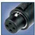
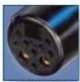
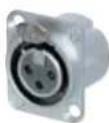
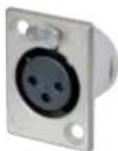
| Connection Type | XLR (Female) |
| Number of Pins | 7 |
| Housing Material | Zinc Die-cast |
| Contact Material | Gold Plated |
| Color | Black / Silver |
| Dimensions | 30 mm diameter (approx) |
| Weight | 50 g (approx) |
| Operating Temperature | -30°C to +80°C |
| Insertion/Extraction Cycles | > 1000 |
| Protection Rating | IP40 |
| Recommended Cable Diameter | 6 - 8 mm |
| Soldering Type | Solder |
| Application | Professional Audio Equipment, DMX |
Frequently Asked Questions - NC7MXX Neutrik
User questions about NC7MXX Neutrik
0 question about this device. Answer the ones you know or ask your own.
Ask a new question about this device
Download the instructions for your Audio Connector in PDF format for free! Find your manual NC7MXX - Neutrik and take your electronic device back in hand. On this page are published all the documents necessary for the use of your device. NC7MXX by Neutrik.
USER MANUAL NC7MXX Neutrik
Neutrik' Part Number Guide
NC3FAH1-B-0-D
| Packaging: | D | Cable connector: bulk packed |
| Assembly: | D | Chassis connector: disassembled push latch |
| Retention: | w/o | Latch lock |
| -0 Retention spring | ||
| -DA Asymmetric PUSH | ||
| Shell: | B Black shell, gold contacts | |
| BAG Black shell, silver contacts | ||
| Grounding: | 0 | Separate ground contact connected to shell, male only |
| 1 | Pin 1 & panel & shell connected, no separate ground contact | |
| 2 | Separate ground contact connected to shell & panel, separate Pin 1 | |
| E Additional ground contacts | ||
| w/o number | No ground/shell contact (except 4/5 pole), female only | |
| Termination: | H | Horizontal PCB mount |
| HL | Lateral left PCB mount | |
| HR | Lateral right PCB mount | |
| L | Solder cups | |
| V | Verticale PCB mount | |
| Y | IDC for wires (no ground) | |
| M3 | Mounting holes with M | 3 thread |
| M25 Mounting holes with M | 2.5 thread | |
| - Not applicable | ||
| Series: | A, AA, B, D, DL, DLX, MPR, P, PX, RX, X, XX | |
| Gender: | F Female | |
| M Male | ||
| Number of Contacts: 2, 3, 4, 5, 6, 7, 8, 12 | ||
| Connector Type: | A | Adaptor |
| AC | powerCON | |
| B | BNC | |
| C | XLR | |
| D dummyPLUG | ||

natural_image
Green circular logo with white stylized 'T' and 'N' symbols (no text or numbers)XLR Connectors
XLR Connectors
Content Page
A glance into the future
maxCON....16
Cable Connectors:
XXSeries....18
EMC-XLR Series 18
RXSeries....19
XX-HESeries....19
XX-14Series....20
XX Crimp Series 20
crystalCON 21
convertCON....21
XX-HD Series 22
XSeries 22
X-HD Series 23
XCCSeries....23
FXSSeries....24
FX-SPECSeries....24
8 + 2 pole XLR Type Data Power Connector 25
TechnicalData 26
Ordering Information 28
Receptacles:
A Series 30
AA Series 30
B Series 31
A / B Series - switch 32
D Series 32
DL Series 33
DLX Series 33
XLR Connectors
natural_image
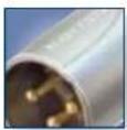
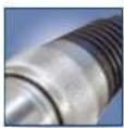
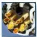
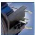
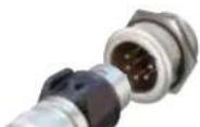
Close-up of electronic equipment with multiple cylindrical pins and connectors (no visible text or symbols)Introduction
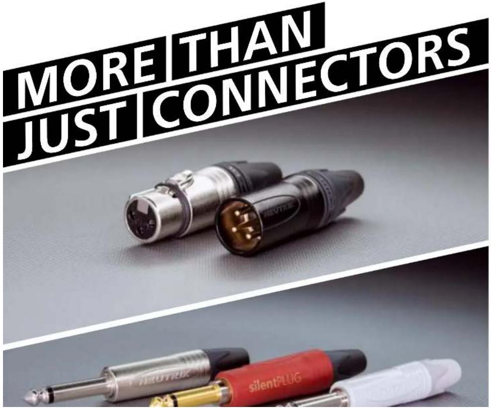
Neutrik XLR connectors are the most well known series of products manufactured by Neutrik, and have provided the professional audio industry a simple, yet striking, concept in connector features. We introduced our first XLR product 40 years ago. Today it is the accepted standard worldwide.
XLR connectors are part of almost every aspect of professional audio; as a microphone connector, in lighting systems, and found in almost any piece of sound equipment in the entertainment industry. The outstanding success of our XLR products is Neutrik's blend of innovation with the highest quality performance.
XLR Connectors
A glance into the future: maxCON® – the new XLR standard
Neutrik's success story began with the construction of the first prototype of a new XLR female cable connector.
The first NC3FC products were delivered in October 1975. During the years 1976, 1977 and 1978 this product range was continuously reworked and improved. In 1983 a new concept was introduced with the X series that has become a world standard.
The further development of the X series leading to the XX series with the unique protection against copying, the hologram, is based on this hundred million times sold X series.
The next generation of audio connectors may come will offer

XLR Connectors

natural_image
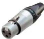
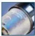
Close-up of a metallic X-ray tube device with black and silver casing (no visible text or symbols)


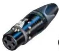
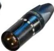
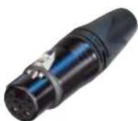
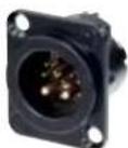
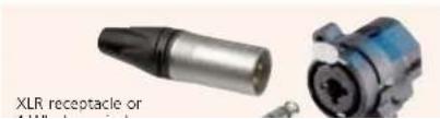
XLR Cable Connectors
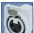
Ergonomic latch design
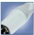
White painted housing

Circumferential ground shield contact
• The next generation of the worldwide accepted standard
- Unique cage type female contact – increases conductivity
- Female contact with "solder stop" for ease of soldering
- Male connector without locking "window" – more robust housing, increases durability
- Improved chuck type strain relief - increases retention force and makes assembly easier and faster
- New ground contact – excellent contact integrity between chassis and cable connector
- Customized branding using translucent ring
- Sleek and ergonomic design – valuable and handy
- 3 pole male / female XLR cable connector with integrated capacitive shield to shell connection to avoid RF-interference and LF-noise
- 360° shield contact on female connector ensures best possible shielding and chassis contact
- Avoid ground loops as there is no LF-shield connection to ground
- Patented

Contact #1
Connector shell

XLR Cable Connectors

Right angle male connector
High temperature resistant insulator
Velour chromium housing
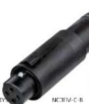
RX Series XX-HE Seri

NC3FRX-BAG

Outlet position

NC3FXX-HF NC3MXX-HF
- Right angle version of the XX Series – only 20 mm wide
• Extra slim right-angle connector - Neutrik chuck type strain relief
- 5 selectable cable outlet positions on female &
7 position on male connectors
NC*FRX

- Exclusive "High End" version of standard XX Series
• Premium velour chromium plating provides soft satin finish - Extra high temperature resistant insulator material rated to 280 °C (536 °F)
• Machined female contacts standard - Insert is dark grey to distinguish it from standard XX-Series insulators
- Flammability UL 94V-0
XLR Cable Connectors
CPUUS
Large cable outlet Ergonomic latch

CPUUS
Neutrik hologram
XX-14 Series
- Special version of the XX Series XLR cable connector for large diameter cables
- Incorporates all the features of the XX product series
- Rear boot features large opening for use with cable O.D. 8.0 – 10.0 mm
-
Bulk packed; must be ordered in multiples of 100
-
3 pin XX Series with crimp contacts
- Accommodates wire size AWG 24 - 22 or 0.22 - 0.34 mm ^2
- Utilize standard B-type crimp tool (acc. IEC 60352-2)
• Absolute leadfree and solderless connection: - RoHs compliance
- health and eco-friendly
- Fast and easy assembly
• Gas-light connection offers a constant contact resistance - Ideal solution for field and on-site termination
XLR Cable Connectors
CPU US
CRYSTALLIZED ^7 - Swarovski Elements
convertCON position male - female
convertCONcrystalICON
NC3FXX-B-CRYSTAI
NC3MXX-B-CRY
natural_image
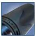
Close-up of a black cylindrical electronic component with no visible text or symbols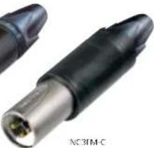
natural_image
Close-up of a black and silver electronic component (no visible text or symbols)- 3 pole XLR XX-Series embellished with CRYSTALLIZED™ - Swarovski Elements
- Exclusively with gold plated contacts, and black chrome housing
• Fancy, noble, valuable, attractive package – an eye-catcher
• With all benefits of the XLR XX-Series
• World's first Unisex XLR cable connector
• 3 pole male and female cable connector in one housing
- Easy selectable gender – converted by sliding housing back and forth
• Substitutes adapters, ideal as an emergency kit
• Exclusively with gold plated contacts
• With all benefits of the XLR XX-Series

Convert
male - female
XLR Cable Connectors
Rubber sealing protection
Neutrik original design
Female locking Male metal locking window
RU
XX-HD Series
natural_image
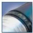
Close-up of a black audio jack connector (no visible text or symbols)NC3FXX-HD-D

natural_image
Close-up of a black plastic connector with three gold pins (no visible text or symbols)- "Heavy duty" cable connector for outdoor use
- Rubber sealing jacket protects against water ingress and mechanical shock
- Dust and water resistant according to IP 67 in the following combinations:
- NC3FXX-HD and NC3MPR-HD
- NC3FXX-HD and NC3MXX-HD
- Gold contacts
- Chuck type strain relief system for secure clamping of cables
- Rugged zinc diecast shell, longlasting and dependable
X Series
NC3FX NC3MX + BSX-5
- The XLR connector standard worldwide
• Available in 3 – 7 pin configurations including 6 pin Switchcraft ^4 configuration - Assembly is quick and easy – no screws or special tools required
- Unique Neutrik chuck type internal strain relief
• Female shell features rubber ring for secure mating to male XLR or microphone
• Sleek profile and compact design - Rugged diecast shell
XLR Cable Connectors
Rubber sealing protection
Metal bushing
Coding ring
X-HD Series

NC5FX-HD NC4MX-HD

XCC Series
NC3FXCC
• "Heavy duty" cable connectors for outdoor use
• All metal design, male stainless steel
- NC*FX-HD mates with NC*MPR-HD chassis connector and NC*MX-HD
• Dust and water resistant according IP 65 in mated condition
• Available in 3 – 5 pin configuration
• Metal bushing including O-ring
- Coaxial ground spring and hex crimp ferrule at cable entrance allow continuous (360°) ground connection to shell which is essential when transmitting low level audio signals
- Includes Zebra coding ring to indicate digital AES signals
- Ground contact uses 6.5 mm (.255") size "E" hex crimp (IEC 60803). Use part # HX-R-BNC with DIE-R-BNC-PT
XLR Cable Connectors

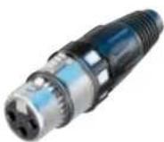
Switch activating ring Locking ring
FXS Series FX-SPEC Series

natural_image
Two metallic and black plastic connectors with red and black end caps, shown against a white background (no text or symbols visible)• Available exclusively in a 3 pin female configuration
• Features a noiseless ON / OFF switch which shorts pins
2 and 3 together muting the signal voltage between conductors
- For use with a microphone that does not have its own On / Off switch
• Rugged zinc diecast shell, long lasting and durable
- Chuck type strain relief system for secure clamping of cables
- Boot with rubber gland gives high protection against
• Available in a 3 pin female standard configuration with gold plated contacts
- Features a locking ring which is secured with a M 2.5 screw and 1.27 mm allen wrench
- Offers the highest security protection for your microphones
- Protects against accidental disconnects and theft
• Black chrome housing and locking ring
- Eliminates movements and noises
Data Power Connector
NEW 8 + 2 pole cable connector

Ergonomic latch design

D-size receptacle
Solder terminationNew 8 + 2 pole
XLR Type Data Power Connectors - 8 + 2 pole
NC10FXX-14-B NC10MD-LX-BNC10FRX-14-B

Suitable for data offering CAT Se performance and power up to 16 A and 50 V - exceeds PoE+ capabilities
- Superior ruggedness compared to RJ45 type connectors
• All metal housing offers best overall RF protection and
electromagnetic shielding - D-size housing provides installation compatibility with industry standard D mounting dimensions
- Receptacle with duplex ground contact for excellent signal integrity
8 + 2 pole Contact Arrangements:
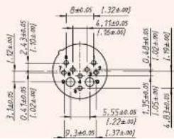
text_image
1.2±0.05 2.3±0.05 1.5±0.05 6±0.05 1.32±0.05 4.7±0.05 1.76±0.05 0.48±0.05 1.02±0.05 1.92±0.05 3.1±0.05 0.4±0.05 1.02±0.05 5.55±0.05 1.22±0.05 1.35±0.05 4.8±0.05 9.3±0.05 1.37±0.05Technical Data
| Specification | XX aXX-14 xCRYSTAL | EMICSeries | XX HDSeries | XX HESeries | RSSeries | XX CrimpSeries | convert-CONSeries | |
| Electrical | ||||||||
| Number of contacts | 3 - 7 ‡ | 3 | 3 | 3 | 3 - 7 | 3 | 3 | |
| Contact resistance | ≤ 3 mΩ | ● | ● | ● | ● | ● | ● | ● |
| Insulation resistance - initial: | >10 GΩ | ● | ● | ● | ● | ● | ● | ● |
| - after damp heat test: | >1 GΩ | ● | ● | ● | ● | ● | ● | ● |
| Dielectric strength | 1.5 kV dc | ● | ● | ● | ● | ● | ● | ● |
| Cable shield-shell connection | choosace | ● | - | ● | ● | ● | ● | ● |
| determined | - | capacitive | - | - | - | - | - | |
| Shielding effectiveness | >55 dB @ 1.3 GHz | - | ● | - | - | - | - | - |
| Lossy ferrite bead on PIN 1 | - | ● | - | - | - | - | - | |
| Rated current per contact | @ 35°C | |||||||
| 3 pole: | 16 A | ● | 5 A | ● | ● | ● | 1 A | ● |
| 4 pole: | 10 A | ● | - | - | - | ● | - | - |
| 5, 6 pole: | 7.5 A | ● | - | - | - | ● | - | - |
| 7 pole: | 5 A | ● | - | - | - | ● | - | - |
| Capacitance between contacts | ||||||||
| 3 pole: | ≤ 4 pF | ● | ● | ● | ● | ● | ● | ● |
| 4, 5, 6 pole: | ≤ 7 pF | ● | - | - | - | ● | - | - |
| 7 pole: | ≤ 9 pF | ● | - | - | - | ● | - | - |
| Rated Voltage | < 50 V ac | ● | ● | ● | ● | ● | ● | ● |
| Mechanical | ||||||||
| Lifetime | >1'000 cycles | ● | ● | ● | ● | ● | ● | ● |
| Insertion/withdrawal force | ≤20 N | ● | ≤50 N | ■ | ● | ● | ● | ■ |
| Cable O.D. range | 3.5 - 8.0 mm | ●2) | ● | 6.0 - 8.0 mm | ● | ● | ● | ● |
| Max. wire size | 3 pole: 2.5 mm/ AWG 14 | ● | AWG 20 | ● | ● | ● | - | ● |
| 4 pole: 1.5 mm/ AWG 16 | ● | - | - | - | ● | - | - | |
| 5, 6, 7 pole: 1.0 mm/ AWG 18 | ● | - | - | - | ● | - | - | |
| Crimp tool: 8.5 mm Flex die size "L" acc. to ILC 60352-2) | - | - | - | - | - | ● | - | |
| Crimp XX: | 0.22 - 0.34 mm2 / AWG 24 - 22 | - | - | - | - | - | ● | - |
| Material | ||||||||
| Shell | Zinc diecast (ZnAMCU1) | ● | ● | - | ● | ● | ● | ● |
| Stainless | steel | - | - | - | - | |||
| Shell plating gal Ni or black Cr | ● | ● | - volucr Cr | ● ● ● | ||||
| Insert Polyamiod PA 6.6 30% GR | ● | ● | ● | PPS 40% Gr | ● ● ● | |||
| Contacts - female 3 pole: Bronze (CuSnB) | ● | ● | ● | Brass | ● ● ● | |||
| - female 4-7 pole & male: Brass (CuZn39Pb3) | ● | ● | ● | ● | ● | - | ● | |
Technical Data
| Specification | X Series | XCC Series | X-HD Series | FXS Series | FX SPEC Series | Data Power XLR | |
| Electrical | |||||||
| Number of contacts | 3 - 7 | 3 | 3 - 5 | 3 | 3 | 8 + 2 | |
| Contact resistance | ≤ 3 mΩ | ● | ● | ● | ● | ● | ● |
| Insulation resistance - initial: | >10 GΩ | ● | ● | ● | ● | ● | ● |
| - after damp heat test: | >1 GΩ | ● | ● | ● | ● | ● | 0.1 GΩ |
| Dielectric strength | 1.5 kV dc | ● | ● | ● | ● | ● | 1 kV dc |
| Cable shield-shell connection | choosable determined | ● | - | ● | - | ● | ● |
| - | crimp | - | - | - | - | ||
| Shielding effectiveness | >55 dB @ 1.3 GHz | - | ● | - | - | - | - |
| Lossy ferrite board on PIN 1 | - | - | - | - | - | - | |
| Rated current per contact | @ 35°C | 16 A (power first) | |||||
| 3 pole: | 16 A | ● | ● | ● | ● | ● | - |
| 4 pole: | 10 A | ● | - | ● | - | - | - |
| 5, 6 pole: | 7.5 A | ● | - | ● | - | - | - |
| 7 pole: | 5 A | ● | - | - | - | - | 3 A (data point) |
| Capacitance between contacts | |||||||
| 3 pole: | ≤ 4 pF | ● | ● | ● | ● | ● | - |
| 4, 5, 6 pole: | ≤ 7 pF | ● | - | ● | - | - | - |
| 7 pole: | ≤ 9 pF | ● | - | - | - | - | - |
| Rated Voltage | < 50 V ac | ● | ● | ● | ● | ● | - |
| Transmission Performance | CAT Se | - | - | - | - | - | ● |
| Mechanical | |||||||
| Lifetime > 1000 cycles | ● | ● | ● | ● | ● | ● | |
| Insertion/ withdrawal force | < 20 N | ● | ● | ● | ● | ● | ● |
| Cable O.D. range | 3.5 - 8.0 mm | ● | 54 - 62 mm | ● | 35 - 70 mm | ● | 80 - 100 mm |
| Max. wire size | 3 pole: 2.5 mm ^2 / AWG 14 | ● | ● | ● | ● | ● | ● (2 power) |
| 4 pole: 1.5 mm ^2 / AWG 16 | ● | - | ● | - | ● | - | |
| 5, 6, 7 pole: 1.0 mm ^2 / AWG 18 | ● | - | ● | - | - | ● (R data) | |
| Crimp tool: | 6.5 mm Hex die pipe (P acc to EC 60809) | - | ● | - | - | - | - |
| Crimp XX: | 0.22 - 0.34 mm ^2 / AWG 24 - 22 | - | - | - | - | - | - |
| Material | |||||||
| Shell | Zinc dilecast (ZnAl4Cu1) | ● | ● | female | ● | ● | ● |
| Stainless steel | - | - | male | - | - | - | |
| Shell plating | gal Ni or black Cr | - | ● | female | ● | ● | black Cr |
| Insert | Polyamide PA 6.6 30% GR | ● | ● | ● | ● | ● | ● |
| Contacts - female 3 pole: | Bronze (CuSn8) | ● | ● | ● | ● | ● | - |
Ordering Information for Cable Connectors
| Female | Male | Shell | Contact - plating | 3 pole | 4 pole | 5 pole | 6 pole | 7 pole |
| XX Series | ||||||||
| NC*FXX | NC*MXX | Nickel | Silver | ● | ● | ● | ● | ● |
| NC*FXX-B | NC*MXX-B | Black Cr | Gold | ● | ● | ● | ● | ● |
| NC*FXX-BAG | NC*MXX-BAG | Black Cr | Silver | ● | ● | ● | ● | ● |
| NC3FXX-WT | NC3MXX-WT | White painted | Silver | ● | - | - | - | - |
| NC3FXX-**-D1 | NC3MXX-**-D1 | Nickel / Black Cr | Silver / Gold | ● | - | - | - | - |
| NC6FSXX2 | NC6MSXX2 | Nickel | Silver | - | - | - | ● | - |
| NC6FSXX-B2 | NC6MSXX-B2 | Black Cr | Gold | - | - | - | ● | - |
| NC6FSXX-BAG2 | NC6MSXX-BAG2 | Black Cr | Silver | - | - | - | ● | - |
| XX-EMC Series | ||||||||
| NC3FXX-EMC | NC3MXX-EMC | Nickel | Gold | ● | - | - | - | - |
| NC3*XX-EMC-B | - | Black Cr | Gold | ● | - | - | - | - |
| RX Series | ||||||||
| NC*FRX | NC*MRX | Nickel | Silver | ● | ● | ● | ● | ● |
| NC*FRX-B | NC*MRX-B | Black Cr | Gold | ● | ● | ● | ● | ● |
| NC*FRX-BAG | NC*MRX-BAG | Black Cr | Silver | ● | ● | ● | ● | ● |
| XX-HE Series | ||||||||
| NC3FXX-HE | NC3MXX-HE | Velbur Chromium | Gold | ● | - | - | - | - |
| XX-14 Series | ||||||||
| NC3FXX-14-D | NC3MXX-14-D | Nickel | Silver | ● | - | - | - | - |
| NC3FXX-14-B-D | NC3MXX-14-B-D | Black Cr | Gold | ● | - | - | - | - |
| NC3FXX-14-BAG-D | NC3MXX-14-BAG-D | Black Cr Silver | ● | - | - | - | - | |
| XX Crimp Series | ||||||||
| NC3FXX-HA | NC3MXX-HA | Nickel | Silver | ● | - | - | - | - |
| NC3FXX-HA-BAG | NC3MXX-HA-BAG | Black Cr | Silver | ● | - | - | - | - |
| convertCON Series | ||||||||
| NC3FM-C | Nickel | Gold | ● | - | - | - | - | |
Ordering Information
Ordering Information for Cable Connectors
| Female | Male | Shell | Contact - plating | 3 pole | 4 pole | 5 pole | 6 pole | 7 pole |
| X Series | ||||||||
| NC*FX | NC*MX | Nickel | Silver | ● | ● | ● | ● | ● |
| NC*FX-B | NC*MX-B | Black Cr | Gold | ● | ● | ● | ● | ● |
| NC*FX-BAG | NC*MX-BAG | Black Cr | Silver | ● | ● | ● | ● | ● |
| NC3FX***-D1 | NC3MX***-D1 | Nickel / Black Cr | Silver / Gold | ● | - | - | - | - |
| NC6PSX2 | NC6MSX2 | Nickel | Silver | - | - | - | ● | - |
| NC6PSX-B2 | NC6MSX-B2 | Black Cr | Gold | - | - | - | ● | - |
| NC6*SX-BAG3 | NC6MSX-BAG3 | Black Cr | Silver | - | - | - | ● | - |
| X-HD Series | ||||||||
| NC*FX-HD | NC*MX-HD | Nickel | Gold | ● | ● | ● | - | - |
| NC3FX-HD-B | NC3MX-HD-B | Metal Black | Gold | ● | - | - | - | - |
| XCC Series | ||||||||
| NC3FXCC | NC3MXCC | Nickel | Gold | ● | - | - | - | - |
| FXS Series | ||||||||
| NC3FXS | - | Nickel | Gold | ● | - | - | - | - |
| NC3FXS-B | - | Black Cr | Gold | ● | - | - | - | - |
| FX-SPEC. Series | ||||||||
| NC3FX-SPEC. | - | Black Cr | Gold | ● | - | - | - | - |
Ordering Information for 8 + 2 pole Data Power Connectors
| Female Male Shell Contact - plating 8 + 2 pole | ||||
| Cable Connector | ||||
| NC10FXX-14-B | NC10MXX-14-B | Black Cr | Gold | ● |
| NC10FRX-14-B | NC10MRX-14-B | Black Cr | Gold | ● |
| Receptacle | ||||
NC10FD-LX-B NC10MD-LX-B Black Cr Gold
XLR Chassis Connectors

91
Smallest receptacle Locking release taoLateral right PCB mount


Ground contact

NEW: Ergonomic asymmetric locking release tab
A Series AA Series

NC3FAH NC3MAV NC3FAAV2 NC3MAAH-1
RU

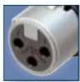
- Smallest XLR receptacles, highest packing density
- Plastic housing
- Various grounding options
• "Tulip" type female contact design with high contact pressure - Selective gold plated contact and PCB termination area for best conductivity and solderability
-
Plastic housing flammability UL 94V-0 for 3 pole version only
-
Front panel cutout and PCB layout 100% compatible to the A Series
- Most cost-effective series
• "Tulip" type female contact design with high contact pressure - Selective gold plated contact and PCB termination area for best conductivity and solderability
• Plastic housing flammability UL 94 HB
NC5FAV
NC5FAH NC3FAAH NC3FAAV-0

XLR Chassis Connectors
Circumferential metal ring

Front panel grounding

Tear drop contact design
NEW: Ergonomic asymmetric locking release tab

B Series

NC3F1V1 NC3M1V NC4F1I NC4M1BV


- The B Series XLR receptable offers the same features as our A Series product line with the added feature of a metal ring
• Metal ring on shell (nickel or black) offers complete EMC and RF protection
• Female versions available latchless - Rear mount only
• "Tulip" type female contact - Plastic housing flammability UL 94V-0 for 3 pole version only
XLR Chassis Connectors

RU
Incorporated switch insert removable
A/B Series - Switch D Ser
NC3FBV2-SW
NC3MBV-5W
NC3FDM3-H-8 NC3MD-V
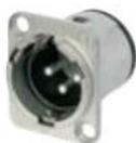
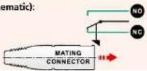
- A and B Series connector with additional switch
• Normally open, normally closed (NO - NC) contact - Switch activated by mating XLR cable connector
Inserting (Schematic):
• 'D' Shape metal shell
• Optimal RF protection using 3 shield contacts
• Horizontal and vertical PCB mount with separate ground contact
- Mounting holes with M3 threads available
- 2 piece connector, insert is removable from shell
• Front locked / unlocked insert
- Special version with screw termination (*M3)
NC3FD-V / NC3FD-H
XLR Chassis Connectors

RU
Locking release tab Horizontal PCB mount

RU
Ground shielding White painted housing
DL Series DLX Series

NC3FD-L-1 NC7MD-L-B-1


NC3FD-LX-HF NC5MD-LX
- Unified 'D' metal shell
• Solder cups on 3 – 7 pole version
• Additional PCB mount on 4 and 5 pole -
Front and rear mountable
-
Next generation of the popular DL Series with greater functionality
- All metal housing works in combination with a new duplex ground contact yielding the best RF protection and ground conductivity in a chassis mount XLR
- Male connector's retention bar replaces plastic design with all metal version
- Unique cage type female contacts on 3 pole version for increased conductivity
- Machined male and female contacts on 4 - 7 pole versions
NC3FD-1-1
NC*EDM3-H
XLR Chassis Connectors
RU
Crimp type contact Circumferential

ground spring
DLX Crimp Series
NC3FD-LX-HA NC3MD-LX-BAG-HA
EMC Series
NC3FDX-EMC-SPTC
• 3 pole DLX Series with crimp contacts
- Accommodates wire size AWG 24 - 22 or 0.22 - 0.34 mm ^2
- Utilizes standard B-type crimp tool (acc. IEC 60352-2)
• Absolute leadfree and solderless connection:
- RoHs compliance
- Health and eco-friendly
- Fast and easy assembly
- Gas-tight connection offers a constant contact resistance
- Ideal solution for field and on-site termination
- 3 pole female XLR chassis connector with integrated capacitive shield to shell connection to avoid RF-interference and LF-noise
- 360° shield contact ensures best possible shielding and
chassis contact
• D flange chassis for panel mount applications - Includes the locking nut of the NC3FX-SPEC for secure
fastening of a gooseneck for instance
• Special flange for large openings available - Patent pending
XLR Chassis Connectors

Sealing Gasket
Through hole fastening

P Series
MPR-HD Series
NC3MPR-HD NC5MPR-HD
NC3FP-1

NC6MP-B
- IP 65 – in combination with NC*FX-HD cable connectors
• Perfect for outdoor applications - Sealing gasket for water tight panel mount
• Gold plated contacts
NC5MPR-HD
• Male and female available in 3 – 6 pin configurations;
7 pin version available in female only
- Smallest available hard wiring receptacles with large solder cups
• Male and female use different mounting hole dimensions and do not fit in same mounting hole
- Front mountable only
- One piece version – insert is NOT removable from shell
- Short female receptacle
- Compatible with Switchcraft" DxM, DxF; Cannon XLRx31, XLRx32
- 6 pole female version available with Switchcraft contact
XLR Chassis Connectors


Front end design Solder termination
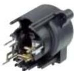
Combo Series
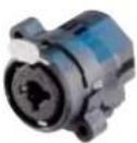
NC197-V

NC10F1-S
• Combined XLR receptacle and 1/4" phone jack
- Attractive "front end" design
- Saves rack space by combining 2 connectors in one housing
• Horizontal or vertical PCB mount or hard wire soldering
- Fully normalled
- Stereo or mono version
- Very low conductor capacitance, therefore suitable for digital audio
- Fastening: Self-tapping Plastite® screws with thread
2.9 x 1.06 and tri-rondular configuration (A screw)
natural_image
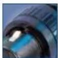
Two mechanical components: a metallic cylindrical device and a blue electrical connector (no visible text or symbols)XLR Chassis Connectors

Hologram

Horizontal PCB mount
Vertical PCB mount NEW: Ergonomic asymmetric locking release tape
Combo A Series

NCJ6FA-V-D

NC16FA-H
NC15TA-V-0
- Combined 3 pole XLR receptacle and 1/4'' phone jack for balanced mic and line or instrument inputs in one XLR housing
- Dramatic space saving – 15 % over the predecessor Combo
- Two connectors in one housing – substantial cost, material and labour saving
• Horizontal and vertical PCB mount available
• 3 pole female XLR combined with stereo TRS jack
- Very low conductor capacitance – ideal for digital audio
- Front panel cut-out compatible with Neutrik XLR A Series
- Branded with unique hologram – guarantees genuine and authentic Neutrik product
Accessories
Colour Coded Accessories
| Part No. | Description |  |
| XLR Cable Connectors | ||
| BSX-* | Colored bushing for X | Series |
| BXX-* | Colored bushing for XX Series | |
| XCR-* | Colored coding ring for X Series | |
| XXR-* | Colored coding ring for XX Series | |
| XLR Chassis Connectors | ||
| ACRF-* | Colored ring for female 4 pole A Series and 4 + 5 pole B Series |  |
| ACRM-* | Colored ring for male 4 pole A Series and 4 + 5 pole B Series | |
| DSS-* | Lettering plate for D Series | |
Accessories
XLR Cable Connectors
| BXX-CR Bushing with translucent coding ring BXX-14 Large bushing set (cable O.D. 8.5 mm) XXCR Translucent coding ring for XX Series |  | 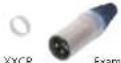 |
| Label Dimensions: 57.9 mm x 6.35 mm - 2.25" W x 0.25" 10 | BXX-CR | xmm sample |
XLR Chassis Connectors
| A-Screw-1-B Plastic* screw 2.9 x 8 |  |  |  | ||||
| B-Screw-1-B TAPTITE* screw 2.5 x 8 | |||||||
| DBA | Dummy-plate for D Series panel cut outs | ||||||
| FDR1 | Round panel mounting flange for | ||||||
| NC3FDX-EMC-SPEC | A Screw | B Screw | DBA | FDR1 | MID | Example | |
| HA-3EXX | Set of 50 female space contacts for crimp XLB | ||||||
Technical
Da
Specification
| A Series | AA Series | B Series | D Series | DL / DLX Series | DLX Crimp | DLX - HE Series |
Electrical
| Number of contacts | 3-5 3 3-5 3 3-7 3 3 | |||||||
| Contact resistance | <6 mA | ● | ● | ● | ● | ● | ● | ● |
| Insulation resistance - initial | >10 GΩ | ● | ● | ● | ● | ● | ● | ● |
| after damp heat test | >1 GΩ | ● | ● | ● | ● | ● | ● | ● |
| Dielectric strength | 1.5 kV dc | ● | ● | ● | ● | ● | ● | ● |
| Rated voltage | <50 V ac | ● | ● | ● | ● | ● | ● | ● |
| Rated current per contact | ||||||||
| 3 pole: 6 A | ● | ● | ● | ● | 16 A | 1 A | 16 A | |
| 4 pole: 6 A | ● | - | ● | - | 10 A | - | - | |
| 5, 6 pole: 3 A | ● | - | ● | - | 7.5 A | - | - | |
| 7 pole: 5 A | - | - | - | - | ● | - | - | |
| Combo XLR + Jack contact | 7.5 A | - | - | - | - | - | - | - |
| Capacitance between contacts | ||||||||
| 3 pole: ≤4 pF | ● | ● | ● | - | ≤4 pF | ≤4 pF | ≤4 pF | |
| 4, 5, 6 pole: ≤7 pF | ● | - | ● | - | ● | - | - | |
| 7 pole: <9 pF | - | - | - | - | ● | - | - | |
Mechanical
| Lifetime | >1'000 mating cycles | ● | ● | ● | ● | ● | ● | ● |
| Insertion / withdrawal force | ≤ 20 N | ● | ● | ● | ● | ● | ● | ● |
| Retention method | ||||||||
| - standard: latch lock | ● | ● | ● | ● | ● | ● | ● | |
| - "0" Version: ≥ 20 N separating force | ● | ● | ● | ● | ● | - | - | |
| Crimp XX | 0.22 - 0.34 mm / AWG 24 - 22 | - | - | - | - | - | ● | - |
Material
| Insert | Polyamide | PA 6.6 30% GR | ● | ● | ● | ● | ● | ● | 155 40% GR |
| Shell | Zinc diecast | ZnAl4Cu1 | - | - | - | ● | ● | ● | ● |
| Shell plating | gal Norback Cr | - | - | ● | ● | ● | ● | velour Cr | |
| Ring | Zinc diecast | ZnAl4Cu1 | - | - | ● | - | - | - | - |
| Contacts | - female 3 pole: Bronze CuSn6 | ● | ● | ● | ● | ● | ● | ● | |
| 4 - 5 pole: Bronze CuSn6 | ● | - | - | - | - | - | - | ||
| 4 - 7 pole: Brass CuZn39Pb3 | - | - | - | - | ● | - | - | ||
| - male: Brass CuZn35Pb2 | ● | ● | ● | ● | ● | ● | ● | ||
| Contact surface | gal 0.2 μm AuCr over 2 μm NiP15 (Tribor) | ● | ● | ● | - | - | - | ● | |
Technical Data
Specification
| MPR-HD Series | P Series | Combo Series | A Combo |
Electrical
| Number of contacts | 3-5 3-7/69 5-10 3/3 | ||||
| Contact resistance XLR: | < 6 mΩ | ● | ● | <10 mΩ | <10 mΩ |
| 1/4" & switching contacts** | ≤ 20 mΩ | - | - | ● | ≤10 mΩ |
| Insulation resistance - initial: | >10 GΩ | ● | ● | ● | ● |
| - after damp heat test: | >1 GΩ | ● | ● | >500 mΩ | ● |
| Dielectric strength | 1.5 kV dc | ● | ● | ● | ● |
| Rated voltage | 50 V ac | ● | ● | ● | ● |
| Rated current per contact | |||||
| 3 pole: | 6 A | 16 A | 16 A - 3 A | ||
| 4 pole: | 6 A | 10 A | 10 A - | - | |
| 5, 6 pole: | 3 A | 7.5 A - 7.5 A | - | - | |
| 7 pole: | 5 A | - | ● | - | - |
| Combo XLR + Jack contact | 7.5 A | - | - | ● | ● |
| Capacitance between contacts | |||||
| 3 pole: | ≤ 7 pF | <4 pf | <4 pf | <2 pf | <2 pf |
| 4, 5, 6 pole: | < 7 pF | ● | ● | - | - |
| 7 pole: | ≤ 9 pf | - | ● | - | - |
Mechanical
| Lifetime | >1'000 mating cycles | ● | ● | ● | ● |
| Insertion/withdrawal force | ≤20 N | ● | ● | 25 N | ● |
| Retention method | |||||
| -standard: | latch lock | ● | ● | ●(DLI) | ●(DLI) |
| -10* Version: | ≥20 N separating force | ● | ● | 25 N | 25 N |
Material
| Insert | Polyamide | FA 6.6 30% GR | ● | ● | ● | ■ |
| Shell | Zinc diecast | ZnAl4Cu1 | ● | ● | - | - |
| Shell plating | galNi or back Cr | M | ● | - | - | |
| Ring | Zinc diecast | ZnAl4Cu1 | - | - | - | - |
| Contacts | - female 3 pole: | Bronze CuSn6 | - | ● | ● | ● |
| 4 - 5 pole: | Bronze CuSn6 | - | - | - | - | |
| 4 - 7 pole: | Brass CuZn39Pb3 | - | ● | - | - | |
| - male: | Brass CuZn35Pb2 | ● | ● | - | - | |
| Contact surface | gal O 2 cm AuCo mes 2 μm Ni15 (Tiber) | - | ● | ● | ||
Ordering Information
Ordering Information for Receptacles
| Female | Male | Shell | Contact | 3 p.b. | 4 am. | 5 gm. | Female | Male | Shell | Contact | 3 p.b. |
| A Series | AA Series | ||||||||||
| NC*FAH-D | Black Plastic Gold - | ● | ● | NC3FAAH | NC3MAAH | Black Plastic | Gold | ● | |||
| NC*MAH | Black Plastic Gold | ● | ● | ● | NC3FAAH-0 | Black Plastic | Gold | ● | |||
| NC*FAH-0 | Black Plastic Gold | ● | ● | ● | NC3FAAH1 | NC3MAAH-1 | Black Plastic | Gold | ● | ||
| NC3MAH-0 | Black Plastic Gold | ● | - | - | NC3FAAH1-0 | Black Plastic | Gold | ● | |||
| NC3FAHL-0 | Black Plastic Gold | ● | - | - | NC3MAAH-0 | Black Plastic | Gold | ● | |||
| NC3FAHR-0 | Black Plastic Gold | ● | - | - | NC3FAAH2 | Black Plastic | Gold | ● | |||
| NC3FAH1-D | Black Plastic Gold | ● | - | - | NC3AAH2-0 | Black Plastic | Gold | ● | |||
| NC3FAH1-0 | Black Plastic Gold | ● | - | - | NC3FAAV | NC3MAAV | Black Plastic | Gold | ● | ||
| NC3FAHL1-D | Black Plastic Gold | ● | - | - | NC3FAAV-0 | Black Plastic | Gold | ● | |||
| NC3MAHL | Black Plastic Gold | ● | - | - | NC3FAAV1 | NC3MAAV-1 | Black Plastic | Gold | ● | ||
| NC3FAH1-L0 | Black Plastic Gold | ● | - | - | NC3FAAV1-0 | Black Plastic | Gold | ● | |||
| NC3FAHR1-D | Black Plastic Gold | ● | - | - | NC3MAAV-0 | Black Plastic | Gold | ● | |||
| NC3MAHR | Black Plastic Gold | ● | - | - | NC3FAAV2 | Black Plastic | Gold | ● | |||
| NC3FAHR1-0 | Black Plastic Gold | ● | - | - | NC3FAAV2-0 | Black Plastic | Gold | ● | |||
| NC3FAH2-D | Black Plastic Gold | ● | - | - | |||||||
| NC3FAH2-0 | Black Plastic Gold | ● | - | - | |||||||
| NC3FAHR2-D | Black Plastic Gold | ● | - | - | A Series = D version come with disassembled Push latch, version with assembled latch omit -D. | ||||||
| NC3FAHR2-0 | Black Plastic Gold | ● | - | - | |||||||
| NC*FAV-D | Black Plastic Gold - | ● | ● | ||||||||
| NC*MAV | Black Plastic Gold | ● | ● | ● | AA Series comes with Push Latch assembled. | ||||||
| NC*FAV-0 | Black Plastic Gold | ● | ● | ● | |||||||
| NC3MAV-0 | Black Plastic Gold | ● | - | - | A / AA Series rear mount only, all PCB mount except Y version = IDC | ||||||
| NC3FAV1-D | Black Plastic Gold ● - - | ||||||||||
| NC3FAV1-0 | Black Plastic Gold | ● | - | - | -DA: with asymmetric push | ||||||
| NC3FAV2-D | Black Plastic Gold | ● | - | - | |||||||
| NC3FAV2-0 | Black Plastic Gold | ● | - | - | 0: Grounding Option *2* | ||||||
| NC5FAV-SW-D | NC5MAV-SW | Black Plastic Gold | - | - | ● | 0: Retention Spring | |||||
Grounding Options
A / AA Series and B Series
Female - 3 pole
Female 4 & 5 pole
Ordering Information
Ordering Information for Receptacles
| Female | Male | Flange | Contact | 3 rule | 4 rule | 5 rule | Female | Male | Shell | Contact | 3 rule | 4 rule | 5 rule | 7 rule |
| B Series | D Series | |||||||||||||
| NC*FBH | Metal | Gold | - | ● | ● | NC3FD-V | NC3MD-V | Nickel | Silver | ● | - | - | - | |
| NC*MBH | Metal | Gold | ● | ● | ● | NC3FD-V-B | NC3MD-V-B | Black Cr | Gold | ● | - | - | - | |
| NC5FBH-B | NC5MBH-B | Black Metal | Gold | - | - | ● | NC3FD-V-BAG | NC3MD-V-BAG | Black Cr | Silver | ● | - | - | - |
| NC3MBH-B | Black Metal | Gold | ● | - | - | NC3IDM3-V | NC3MDM3-V | Nickel | Silver | ● | - | - | - | |
| NC3MBH-O | Metal | Gold | ● | - | NC3FDM3-V-B | NC3MDM3-V-B | Black Cr | Gold | ● | - | - | - | ||
| NC3FBH1 | NC3MBH-1 | Metal | Gold | ● | - | - | NC3FD-H | NC3MD-H | Nickel | Silver | ● | - | - | - |
| NC3FBH1-B | Black Metal | Gold | ● | - | - | NC3FD-H-B | NC3MD-H-B | Black Cr | Gold | ● | - | - | - | |
| NC3FBH-L1 | Metal | Gold | ● | - | - | NC3FD-H-BAG | NC3MD-H-BAG | Black Cr | Silver | ● | - | - | - | |
| NC3MBHL | Metal | Gold | ● | - | - | NC3FDM3-H | NC3MDM3-H | Nickel | Silver | ● | - | - | - | |
| NC3MBHI-B | Black Metal | Gold | ● | - | - | NC3FDM3-H-B | NC3MDM3-H-B | Black Cr | Gold | ● | - | - | - | |
| NC3FBH2 | Metal | Gold | ● | - | - | NC3IDM3-HBAG | NC3MDM3-HBAG | Black Cr | Gold | ● | - | - | - | |
| NC3FBH2-B | Black Metal | Gold | ● | - | - | |||||||||
| NC3MBHR | Metal | Gold | ● | - | - | DLX Series | ||||||||
| NC3MBHR-B | Black Metal | Gold | ● | - | - | NC*FD-LX | NC*MD-LX | Nickel | Silver | ● | ● | ● | ● | |
| NC3FBH1-E | NC3MBV-L | Metal | Gold | ● | - | - | NC*FD-LX-B | NC*MD-LX-B | Black Cr | Gold | ● | ● | ● | ● |
| NC3FBH2-E | Metal | Gold | ● | - | - | NC*FD-LX-BAG | NC*MD-LX-BAG | Black Cr | Silver | ● | ● | ● | ● | |
| NC3MBH-B | Metal | Gold | ● | - | - | NC*FD-LX-M3 | NC*MD-LX-M3 | Nickel | Silver | ● | ● | ● | - | |
| NC*MBV | Metal | Gold | ● | ● | ● | NC3FD-LX-HE | NC3MD-LX-HE | Velour Cr | Gold | ● | - | - | - | |
| NC*FBV | Metal | Gold | - | ● | ● | NC3FD-LX-WT | NC3MD-LX-WT | White | Silver | ● | - | - | - | |
| NC5FBV-B | NC5MBV-B | Black Metal | Gold | - | - | ● | NC6FSD-LX | NC6MSD-LX | Nickel | Silver | - | - | ● | - |
| NC3IBV1 | Metal | Gold | ● | - | - | |||||||||
| NC3FBV1-B | Black Metal | Gold | ● | - | - | DL Series | ||||||||
| NC3FBV2 | Metal | Gold | ● | - | - | NC*FD-L1 | NC*MD-L1 | Nickel | Silver | ● | ● | ● | ● | |
| NC3FBV2-B | Black Metal | Gold | ● | - | - | NC*FD-LB-1 | NC*MD-LB-1 | Black Cr | Gold | ● | ● | ● | ● | |
| NC3MBV-O | Metal | Gold | ● | - | - | NC*FD-LBAG-1 | NC*MD-LBAG-1 | Black Cr | Silver | ● | ● | ● | ● | |
| NC3MBV-1 | Metal | Gold | ● | - | - | NC*FDM3-I-1 | NC*MDM3-I-1 | Nickel | Silver | ● | ● | ● | - | |
| NC3FBV2-SW | NC3MBV-SW | Metal | Gold | ● | - | - | NC3FDM3-BAG-1 | NC3MDVM3-BAG-1 | Black Cr | Silver | ● | - | - | - |
| NC5FBV-SW | NC5MBV-SW | Metal | Gold | - | - | ● | NC3FD-LI-HE | NC3MD-LI-HE | Velour Cr | Gold | ● | - | - | - |
| NC*FDM3-H | NC*MDM3-H | Nickel | Silver | ● | ● | ● | - | |||||||
| NC*FDM3-HB | NC*MDM3-HB | Nickel | Silver | ● | ● | ● | - | |||||||
| NC*FDM3-HBAG | NC*MDM3-HBAG | Black Cr | Silver | ● | ● | ● | - | |||||||
| NC3FD-S-1-B NC3MD-S-1-B Black Cr Silver | ||||||||||||||
| 0: Retention spring on request | ||||||||||||||
Ordering Information
Ordering Information for Receptacles
| Female | Male | Shell | Contact | 3 | 4 | 5 | 6 | 7 | Shell | Contact | 5 | 6 | 9 | 10 | |||
| EMC XLR | Combo A Series | ||||||||||||||||
| NC3FDX-EMC-SPEC | Black Cr | Gold | ● | - | - | - | - | NC16FA-H | Black plastic | Gold | - | ● | - | - | |||
| NC16FA-H-0 | Black plastic | Gold | - | ● | - | - | |||||||||||
| Accessories | NC16FA-H-DA | Black plastic | Gold | - | ● | - | - | ||||||||||
| NC16FA-V | Black plastic | Gold | - | ● | - | - | |||||||||||
| FDR-1 | Black round panel mounting flange with screws for larger panel cut-outs | NC16FA-V-0 | Black plastic | Gold | - | ● | - | - | |||||||||
| NC16FA-V-DA | Black plastic | Gold | - | ● | - | - | |||||||||||
| P Series | Combo Series | ||||||||||||||||
| NC*FP-1 | Nickel | Silver | ● | ● | ● | ● | ● | NC1*FI-H | Black plastic | Gold | ● | ● | ● | ● | |||
| NC*MP | Nickel | Silver | ● | ● | ● | ● | - | NC1*FI-H-0 | Black plastic | Gold | ● | ● | ● | ● | |||
| NC*FP-B-1 | Black Cr | Gold | ● | ● | ● | ● | ● | NC1*FI-S | Black plastic | Gold | ● | ● | ● | ● | |||
| NC*MP-B | Black Cr | Gold | ● | ● | ● | ● | - | NC1*FI-S-0 | Black plastic | Gold | ● | ● | ● | ● | |||
| NC*FP-BAG-1 | NC*MP-BAG | Black Cr | Silver | ● | ● | ● | ● | - | NC1*FI-V | Black plastic | Gold | ● | ● | ● | ● | ||
| NC1*FI-V-0 | Black plastic | Gold | ● | ● | ● | ● | |||||||||||
| MPR-HD Series | Contact # | ||||||||||||||||
| - | NC*MPR-HD | Nickel | Gold | ● | ● | ● | - | - | 1 | 2 | 3 | T | R | S | TN | RN | |
| NC16F*- | x | x | x | x | x | ||||||||||||
| NC16F*- | x | x | x | x | x | ||||||||||||
| NC19F*- | x | x | x | x | x | x | x | x | |||||||||
| NC110F*- | x | x | x | x | x | x | x | x | |||||||||
Panel Cutouts
A/AA/B Series D/DL/DLX Series P Series Female P Series Male Combo MPR Series


Assembly Tools