SD52C232-HC-LA - Security Camera Dahua Technology - Free user manual and instructions
Find the device manual for free SD52C232-HC-LA Dahua Technology in PDF.

User questions about SD52C232-HC-LA Dahua Technology
0 question about this device. Answer the ones you know or ask your own.
Ask a new question about this device
Download the instructions for your Security Camera in PDF format for free! Find your manual SD52C232-HC-LA - Dahua Technology and take your electronic device back in hand. On this page are published all the documents necessary for the use of your device. SD52C232-HC-LA by Dahua Technology.
USER MANUAL SD52C232-HC-LA Dahua Technology
HDCVI Speed Dome & PTZ Camera
User's Manual

natural_image
Abstract geometric design with gray and blue color blocks (no text or symbols)Foreword
General
This manual introduces the functions and operations of the HDCVI speed domes and PTZ cameras (hereinafter referred to as "the Device").
Safety Instructions
The following categorized signal words with defined meaning might appear in the manual.
| Signal Words | Meaning | |
| [2C05] | DANGER | Indicates a high potential hazard which, if not avoided, will result in death or serious injury. |
 | WARNING | Indicates a medium or low potential hazard which, if not avoided, could result in slight or moderate injury. |
 | CAUTION | Indicates a potential risk which, if not avoided, could result in property damage, data loss, lower performance, or unpredictable result. |
| [YXXX] | TIPS | Provides methods to help you solve a problem or save you time. |
| [TD20] | NOTE | Provides additional information as the emphasis and supplement to the text. |
Revision History
| Version | Revision Content | Release Time |
| V1.0.0 | First release. | June 2020 |
About the Manual
- If there is any uncertainty or controversy, we reserve the right of final explanation.
Important Safeguards and Warnings
The manual will help you to use the Device properly. Read the manual carefully before using the Device, and keep it well for future reference.
Operating Requirements
- Avoid heavy stress, violent vibration, and water splash during transportation, storage, and installation. Complete package is necessary during the transportation. We assume no responsibility for any damage or problem caused by the incomplete package during the transportation.
- To avoid damage, protect the Device from falling down and heavy vibration. Arrange more than one person to move the Device when necessary.
- Buckle the safety hook before installing the Device if it is included.
- Keep the Device away from devices that generate electromagnetic field like televisions, radio transmitters, electromagnetic devices, electric machine, transformers, and speakers; otherwise image quality will be influenced.
- Keep the Device away from smoke, vapor, heat, and dust.
- Do not install the Device near heating furnace, spotlight, and other heat sources. If it is installed on ceiling, in kitchen or near boiler room, the Device temperature might rise.
- Do not dissemble the Device; otherwise it might cause dangers or device damage. Contact your local retailer or customer service center for internal setup or maintenance requirement.
- Make sure that there is no metal, or inflammable, explosive substance in the Device; otherwise it might cause fire, short-circuit, or other damage. Power off the Device and disconnect the power cord immediately if there is water or liquid falling into the Device. And contact your local retailer or customer service center. Avoid sea water or rain eroding the Device.
- Avoid aiming the lens at intense light source, including sunlight, and incandescent light:
Requirements for Lifting the Device
- Use secure lifting appliances suitable for the installation place and the product installation mode.
- Make sure that the selected tools reach the installation height and have high safety performance.
Safety Requirements
- All installation and operations shall conform to local electrical safety regulations.
- The power source shall conform to the requirements of the Safety Extra Low Voltage (SELV) standard, and supply power with rated voltage which conforms to Limited Power Source requirement according to IEC60950-1. Note that the power supply requirement is subject to the device label.
- Use the power adapter recommended by the manufacturer.
- For the Device that supports laser, do not aim the laser directly at eyes. And keep a proper distance from the flammable to avoid fire.
- Do not connect several devices to one power adapter; otherwise it might result in overheat or fire if it exceeds the rated load.
- Make sure that the power is off when you connect the cables, install or uninstall the Device.
- Power off the Device and disconnect the power cord immediately if there is any smoke, disgusting smell, or noise from the Device. And contact your local retailer or customer service center.
- Contact your local retailer or customer service center if the Device is abnormal. Do not disassemble or repair the Device by yourself. We assume no responsibility for any problems caused by unauthorized modifications, disassembly or repair, incorrect installation or use, and overuse of certain components.
Table of Contents
Foreword .... I
Important Safeguards and Warnings.... III
1 Overview....1
1.1 Introduction.... 1
1.2 Features .... 1
2 Preparation....4
3 OSD Menu 6
3.1 Self-test 6
3.2 Opening the OSD Menu....6
3.3 Menu Index....8
3.4 Menu Functions and Operations....9
3.4.1 System Settings....9
3.4.1.1 Checking System Information....9
3.4.1.2 Setting Address Information.... 10
3.4.1.3 Setting PTZ Life Warning.... 12
3.4.1.4 Setting System Time 13
3.4.1.5 Setting North Direction.... 15
3.4.1.6 Setting Language ...... 15
3.4.1.7 Setting Switch Type 16
3.4.1.8 Setting Video Output Mode.... 17
3.4.1.9 Setting Audio Mode.... 18
3.4.1.10 Restoring the Device to Factory Default Settings.... 19
3.4.3.4 Setting Focus.... 35
3.4.3.5 Setting Image Adjustment.... 36
3.4.3.6 Setting Defog 37
3.4.3.7 Setting Zoom Speed.... 38
3.4.3.8 Setting Sharpness.... 39
3.4.3.9 Setting Sharpness Suppression.... 39
3.4.3.10 Setting Digital Zoom....40
3.4.3.11 Setting Picture Flip.... 41
3.4.3.12 Lens Initialization 42
3.4.3.13 Setting Picture Mode 43
3.4.3.14 Setting Camera Maintenance.... 44
3.4.3.15 Restoring the Camera to Factory Default Settings 45
3.4.3.16 Restarting the Camera 46
3.4.4 Function Settings.... 47
3.4.4.1 Setting Preset 48
3.4.4.2 Setting Pan....49
3.4.4.3 Setting Scan....50
3.4.4.4 Setting Tour....51
3.4.4.5 Setting Pattern....52
3.4.4.6 Setting Idle Motion 53
3.4.4.7 Setting Time Task....54
3.4.4.8 Setting Privacy Masking....55
3.4.4.9 Setting PTZ Speed....57
3.4.4.10 Setting Zero 57
3.4.4.11 Setting Power Up....58
1 Overview
1.1 Introduction
The Device is integrated with clear image, digitization, and intelligence. It adopts new design, and is easy to install. After installing the Device, the overall aesthetics of the monitoring site is not affected.
1.2 Features
HD Video
The image resolution is in megapixels.
Transmission without Any Loss
The data can be transmitted for up to 500 meters through 75-3 coaxial cable without any loss.

The function is available on select models.
Coaxial Control
The Device can be controlled through coaxial signal.
OSD Menu
With the OSD menu, you can see the device information, and set the functions and
forth to display image at a certain speed in a certain range.
Tour
You can add several presets to a tour in the order you need, and then the Device can move back and forth at the defined interval in the order you need.
Pattern
Pattern means a record of a set of operations that users make to the Device. The operations include horizontal and vertical movements, zoom and preset calling. Record and save the operations, and then you can call the pattern path directly.
Privacy Masking
You can set a masked region in the monitoring screen to protect privacy. The masked area moves as the Device rotates horizontally and vertically, and it changes with the image size.
Alarm Linkage
The Device supports up to 7 NO or NC digital input ports and 2 NO alarm output ports. When alarms are triggered, the defined linked operations can be performed.
Auto Flip
You can track objects manually. When the object passes below the camera, you can operate the joystick on the keyboard to make the Device auto flip 180° horizontally to ensure tracking continuity.
Power-on Self-Test
The Device can perform self-test when it is powered on, which mainly includes self-test of the motor in the horizontal and vertical directions, self-test of camera zooming, and displaying system information.
Dav/Night Switch
Idle Motion
The Device performs a defined action when it does not receive any valid command within a certain period.
Power Up
The Device performs power-up actions automatically after restarting and self-test, which includes auto, preset, scan, tour, pattern and none.
Image Stabilization and Flip
You can enable the image stabilization and image flip through the OSD menu. With the image stabilization function, the image is more stable when the Device is in an environment with vibration. With the image flip function, viewing image is more convenient.

The function depends on the device module.
2 Preparation
The Device is intended to use with matched back-end devices such as HCVR, DVR, and XVR. The manual takes using with XVR as an example.
Before controlling the Device, you need to set the control mode and protocol on the back-end device.
Step 1 Connect the Device to the XVR, and then connect the XVR to a display.
Step 2 Connect all devices to the power supply.
The Device is powered on, and the live interface is displayed.
Step 3 Right-click on the interface, select Main Menu > Camera > PTZ, and then select control mode and protocol as needed.

- If you select HDCVI for Control Mode, HDCVI3.0 and HDCCTV2.0 can be selected for Protocol. But before using HDCCTV2.0, you need to connect the Device to the XVR with ab cable. You can keep the default values for other parameters.
- If you select Serial Port for Control Mode, PELCOD and PELCOP can be selected for Protocol. Before using these two protocols, you need to connect the Device to the XVR with ab cable.
If selecting PELCOD, you need to enter the Address = device address - 1. For example, if the device address is 1, enter 0 for the address. The device address can be found in System Setting > Addr Information.
If selecting PELCOP, you need to enter the device address.
Figure 2-1 Set control mode and protocol

text_image
Channel 1 Speed 5 Zoom + Focus + Iris + Type Control Mode HDCV1 Protocol HDCVT3.0 Address 1 Band Rate 9600 Data Fix 8 Stop Fix 1 Parity None Copy to Apply Back
You can set the video output mode (CVI, TVI, AHD or SD) through DIP switch or OSD menu. For details, see the corresponding installation guide.
3 OSD Menu
3.1 Self-test
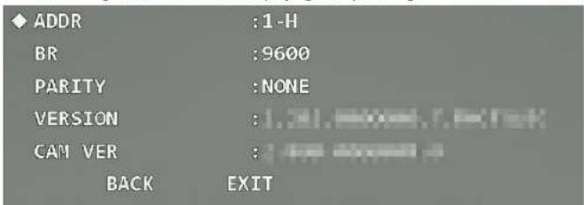
After you install and power on the Device, it will perform self-test. If the self-test is normal, device information such as address, baud rate, parity, PTZ version, and module version is displayed. The information will disappear after the Device receives the first valid control command or the display time is over 20 s.
Figure 3-1 Information displaying after powering-on
text_image
ADDR :1-H BR :9600 PARITY :NONE VERSION :1.31.80000.7.4000 CAM VER : BACK EXITTable 3-1 Parameter description
| Parameter | Description |
| ADDR | Address info of the Device. 1 represents address No.; -H represents hardware address mode. |
| BR | Baud rate. It is the communication baud rate currently used by Device. |
Figure 3-2 PTZ control

text_image
Speed 5 - Zoom + - Focus + - Iris +Step 2 Click to unfold the PTZ control panel, and then click to open the OSD menu.
Figure 3-3 Opening the menu

text_image
Speed 5 - Zoom + - Focus + - Iris + No. 0Step 3 Click up and down buttons to select menu item, click left and right buttons to select parameter value, and then click Enter to confirm it.
Figure 3-4 PTZ menu
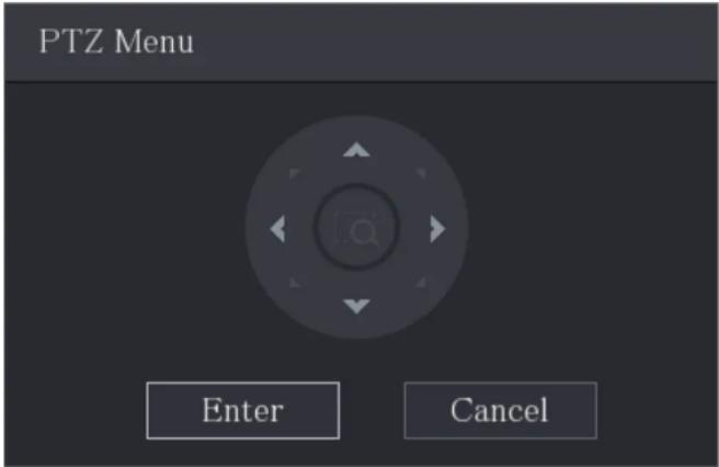
text_image
PTZ Menu Enter Cancel3.3 Menu Index

- ERR on the menu means that there is an error about the parameter. In this case, you can restore the Device to factory default settings.
- The parameters vary with different models, and the actual product shall prevail. The menu items listed below are for reference.
Table 3-2 Menu index
| .. | .. |
3.4 Menu Functions and Operations
3.4.1 System Settings
Open the OSD menu, move the cursor to System Setting, and then click Enter to enter the second-level menu.
Figure 3-5 System settings
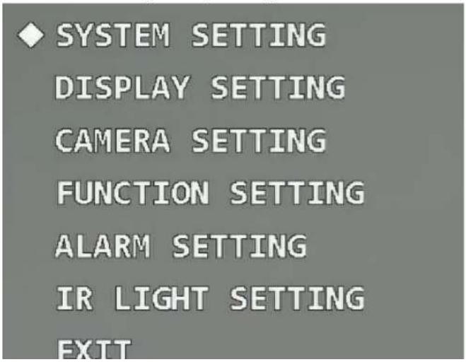
text_image
◆ SYSTEM SETTING DISPLAY SETTING CAMERA SETTING FUNCTION SETTING ALARM SETTING IR LIGHT SETTING EXITFigure 3-6 System information (1)
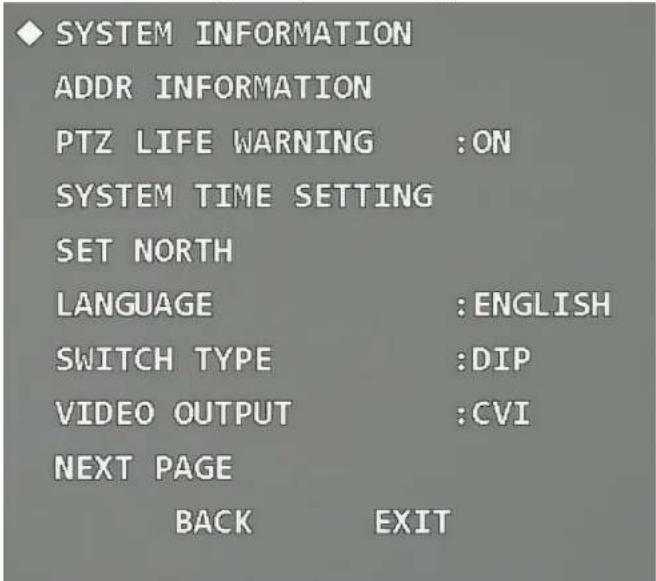
text_image
SYSTEM INFORMATION ADDR INFORMATION PTZ LIFE WARNING :ON SYSTEM TIME SETTING SET NORTH LANGUAGE :ENGLISH SWITCH TYPE :DIP VIDEO OUTPUT :CVI NEXT PAGE BACK EXITFigure 3-7 System information (2)

text_image
ADDR :1-H BR :9600Figure 3-8 Address information (1)

text_image
SYSTEM INFORMATION ◆ ADDR INFORMATION PTZ LIFE WARNING :ON SYSTEM TIME SETTING SET NORTH LANGUAGE :ENGLISH SWITCH TYPE :DIP VIDEO OUTPUT :CVI NEXT PAGE BACK EXITFigure 3-9 Address information (2)

text_image
ADDR TYPE :HARD ADDR-HARD :1
Select address type according to the application scene. You can selectHard if you can use DIP switch conveniently; otherwise selectSoft.
- If you select Hard, the hardware address that you set through DIP switch is used, and the address cannot be modified.
- If you select Soft, the software address can be modified directly on the OSD menu; the address range is from 0 to 255.
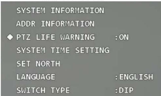
3.4.1.3 Setting PTZ Life Warning
Move the cursor to PTZ Life Warning, and then click left and right buttons to select On or Off. The function is enabled by default.
Figure 3-10 Set PTZ life warning
text_image
SYSTEM INFORMATION ADDR INFORMATION ◆ PTZ LIFE WARNING :ON SYSTEM TIME SETTING SET NORTH LANGUAGE :ENGLISH SWITCH TYPE :DIPFigure 3-11 PTZ life warning
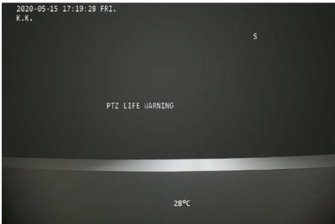
text_image
2020-05-15 17:19:28 FRI. K.K. S PTZ LIFE WARNING 28°C3.4.1.4 Setting System Time
Step 1 Move the cursor to System Time Setting, and then click Enter to enter the third-level menu.
Figure 3-12 Set system time (1)

text_image
SYSTEM INFORMATION ADDR INFORMATION PTZ LIFE WARNING :ON ◆ SYSTEM TIME SETTING SET NORTH LANGUAGE :ENGLISH SWITCH TYPE :DIP VIDEO OUTPUT :CVI NEXT PAGE BACK EXITFigure 3-13 Set system time (2)

text_image
YEAR : 2020 MONTH : 6Device. Step 3 (Optional) Enable Time Sync to synchronize the time of the Device with that of the XVR if the XVR supports time sync. The time will be restored to default value after restarting the Device if time sync is not enabled.
Step 4 Move the cursor to Save, and then click Enter.
3.4.1.5 Setting North Direction
Step 1 Adjust the monitoring direction of the Device to the north through PTZ direction buttons.
Step 2 Move the cursor to Set North, and then click Enter. OK is displayed if the setting takes effect.
Figure 3-14 Set north

text_image
SYSTEM INFORMATION ADDR INFORMATION PTZ LIFE WARNING :ON SYSTEM TIME SETTING SET NORTH LANGUAGE :ENGLISHFigure 3-15 Set language
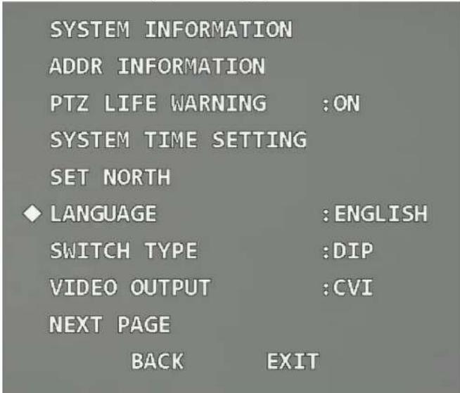
text_image
SYSTEM INFORMATION ADDR INFORMATION PTZ LIFE WARNING :ON SYSTEM TIME SETTING SET NORTH ♦ LANGUAGE :ENGLISH SWITCH TYPE :DIP VIDEO OUTPUT :CVI NEXT PAGE BACK EXIT3.4.1.7 Setting Switch Type
Move the cursor to Switch Type, click left and right buttons to select OSD or DIP, and then click Enter.
Figure 3-16 Set switch type

text_image
SYSTEM INFORMATION ADDR INFORMATION PTZ LIFE WARNING :ON SYSTEM TIME SETTING SET NORTH LANGUAGE :ENGLISH ◆ SWITCH TYPE :DIP VIDEO OUTPUT :CVI NEXT PAGE BACK EXIT- If selecting OSD, you can change the video output mode through OSD menu.
- If selecting DIP, you can only change the video output mode through DIP switch on the Device.
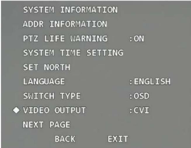
3.4.1.8 Setting Video Output Mode

Figure 3-17 Set video output mode
text_image
SYSTEM INFORMATION ADDR INFORMATION PTZ LIFE WARNING :ON SYSTEM TIME SETTING SET NORTH LANGUAGE :ENGLISH SWITCH TYPE :OSD VIDEO OUTPUT :CVI NEXT PAGE BACK EXIT• CVI: High definition video.
• SD: Standard definition video.
• TVI and AHD: Apply to the third-party back-end devices. Select them as needed.
3.4.1.9 Setting Audio Mode
Move the cursor to Audio Mode, click left and right buttons to select On or Off, and then click Enter.
To make the audio take effect, in addition to enable audio here, you still need to do the following operations.
-
Connect an external sound pickup device to the Device.
-
Go to the main menu of the XVR, select Camera > Encode > Audio/Video, click More in the Main Stream section, select the Audio check box, and then set HDCVI as Audio Source.
-
Go to the Live interface of the XVR, and then click the Sound button in the corresponding channel.
- Off: Disable the audio of the live video.
3.4.1.10 Restoring the Device to Factory Default Settings
Move the cursor to the Factory Default, and then click Enter to restore the Device to factory default settings.

All configurations will be restored to factory default settings if you perform this operation. Be cautious.
Figure 3-19 Factory default

text_image
AUDIO MODE :ON ◆ FACTORY DEFAULT RESTART BACK EXITFigure 3-20 Restart
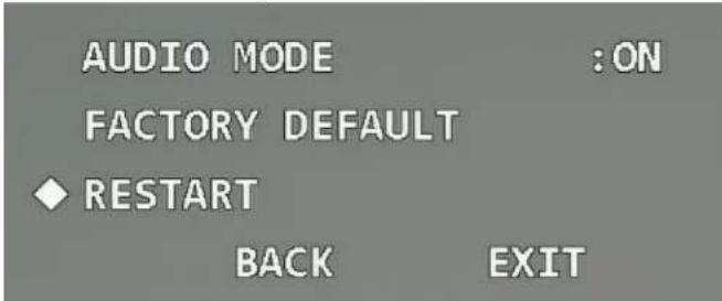
text_image
AUDIO MODE :ON FACTORY DEFAULT ◆ RESTART BACK EXIT3.4.2 Display Settings
Open the OSD menu, move the cursor to Display Setting, and then click Enter to enter the second-level menu.
Figure 3-21 Display settings

text_image
PRESET TITLE :ON AZIMUTH DISP :OFF TIME DISP :OFF POSITION :OFF ZOOM DISP :OFF INSIDE TEMP :°C TITLE DISP :OFF ALARM DISP :OFF PATTERN DISP :OFF BACK EXIT3421 Setting Preset Title Display
Figure 3-22 Preset title

text_image
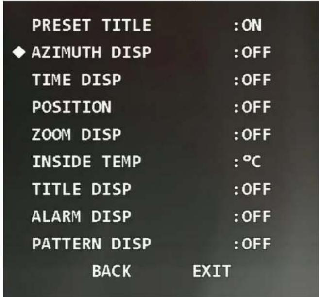
PRESET TITLE :ON AZIMUTH DISP :OFF TIME DISP :OFF POSITION :OFF ZOOM DISP :OFF INSIDE TEMP :°C TITLE DISP :OFF ALARM DISP :OFF PATTERN DISP :OFF BACK EXIT3.4.2.2 Setting Azimuth Display
You can select whether to display the current PTZ coordinate of the Device on the monitoring screen.
Figure 3-23 Azimuth display
text_image
PRESET TITLE :ON ◆ AZIMUTH DISP :OFF TIME DISP :OFF POSITION :OFF ZOOM DISP :OFF INSIDE TEMP :°C TITLE DISP :OFF ALARM DISP :OFF PATTERN DISP :OFF BACK EXIT3.4.2.3 Setting Time Display
You can select whether to display the current time of the Device on the monitoring screen.
Figure 3-24 Time display

text_image
PRESET TITLE :ON AZIMUTH DISP :OFF ◆ TIME DISP :OFF POSITION :OFF ZOOM DISP :OFF INSIDE TEMP :°C TITLE DISP :OFF ALARM DISP :OFF PATTERN DISP :OFF BACK EXIT3.4.2.4 Setting Position Display
You can select whether to display the deviation angle compared with the reference position of the current lens on the monitoring screen.
Figure 3-25 Position display

text_image
PRESET TITLE :ON AZIMUTH DISP :OFF TIME DISP :OFF ◆ POSITION :OFF ZOOM DISP :OFF INSIDE TEMP :°C TITLE DISP :OFF ALARM DISP :OFF PATTERN DISP :OFF BACK EXIT3.4.2.5 Setting Zoom Display
Figure 3-26 Zoom display

text_image
PRESET TITLE :ON AZIMUTH DISP :OFF TIME DISP :OFF POSITION :OFF ♦ ZOOM DISP :OFF INSIDE TEMP :°C TITLE DISP :OFF ALARM DISP :OFF PATTERN DISP :OFF BACK EXIT3.4.2.6 Setting Internal Temperature Display
You can select whether to display the internal temperature of the Device on the monitoring person.
Figure 3-27 Inside temperature

text_image
PRESET TITLE :ON AZIMUTH DISP :OFF TIME DISP :OFF POSITION :OFF ZOOM DISP :OFF INSIDE TEMP :°C TITLE DISP :OFF ALARM DISP :OFF PATTERN DISP :OFF BACK EXIT3.4.2.7 Setting Title Display
You can select whether to display information such as location of the Device on the monitoring screen. The title description can be set through the control terminal or in the Channel Title section of Function Settings.
Figure 3-28 Title display

text_image
PRESET TITLE :ON AZIMUTH DISP :OFF TIME DISP :OFF POSITION :OFF ZOOM DISP :OFF INSIDE TEMP :°C TITLE DISP :OFF ALARM DISP :OFF PATTERN DISP :OFF BACK EXIT3.4.2.8 Setting Alarm Display
Figure 3-29 Alarm display
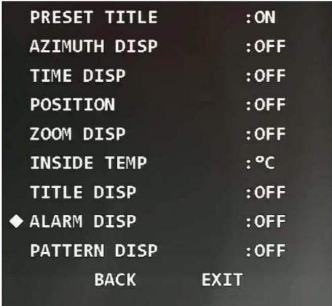
text_image
PRESET TITLE :ON AZIMUTH DISP :OFF TIME DISP :OFF POSITION :OFF ZOOM DISP :OFF INSIDE TEMP :°C TITLE DISP :OFF ♦ ALARM DISP :OFF PATTERN DISP :OFF BACK EXIT3.4.2.9 Setting Pattern Display
You can select whether to display the percentage of the current location out of the total pattern
Figure 3-30 Pattern display
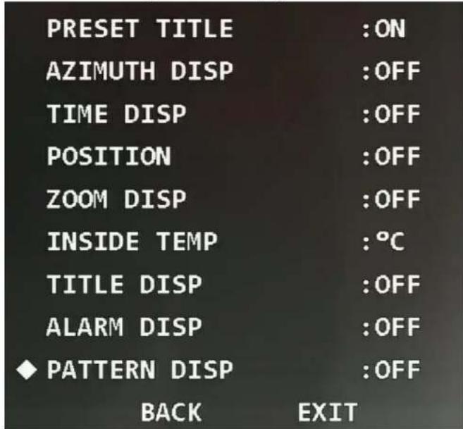
text_image
PRESET TITLE :ON AZIMUTH DISP :OFF TIME DISP :OFF POSITION :OFF ZOOM DISP :OFF INSIDE TEMP :°C TITLE DISP :OFF ALARM DISP :OFF ◆ PATTERN DISP :OFF BACK EXIT3.4.3 Camera Settings
Open the OSD menu move the cursor to Camera Settings and then click Enter to enter the
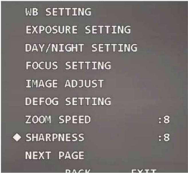
Figure 3-31 Camera settings

text_image
WB SETTING EXPOSURE SETTING DAY/NIGHT SETTING FOCUS SETTING IMAGE ADJUST DEFOG SETTING ZOOM SPEED :8 SHARPNESS :8 NEXT PAGE BACK EXIT3.4.3.1 Setting White Balance
White balance means the restoration of white object, which can calibrate the color temperature
- Move the cursor to B Gain, and then click left and right buttons to set B gain value.
- Select other modes
Click left and right buttons to select others WB modes as needed. You can select Auto, ATW, Outdoor, Indoor, Street Lamp, NA Lamp, or Natural.
Table 3-3 WB mode description
| Mode | Description |
| Manual | Configure red and blue gain manually; the system auto compensates WB according to color temperature. |
| Auto | The system compensates WB according to color temperature to ensure color precision. The mode is selected by default. |
| ATW | The system compensates WB automatically. Compared with Auto mode, the color temperature range is wider, but the precision and recovery capability are weaker. |
| Outdoor | The system auto compensates WB to most outdoor environments with natural or artificial light to ensure color precision. |
| Indoor | Used for indoor environments. |
| Street Lamp | The system compensates WB to outdoor night scenes to ensure color precision. |
| NA Lamp | Used for scenes with sodium lamps. |
| Natural | The system auto compensates WB to environments without artificial light to ensure color precision. |
3.4.3.2 Setting Exposure
You can set exposure to control the amount of light per unit area reaching the electronic image sensor by adjusting parameters.
Class 4: Uses the consensus. Functional Setting and their click. Future is sensitive to the kind level
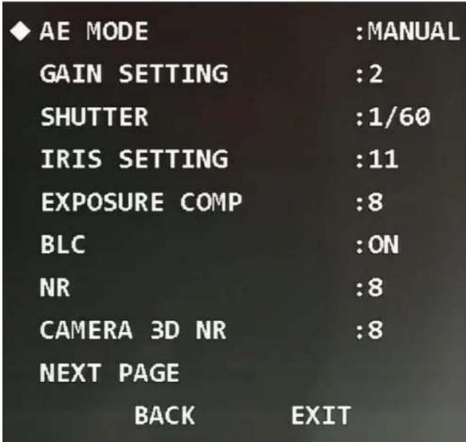
Figure 3-33 Set exposure
text_image
AE MODE :MANUAL GAIN SETTING :2 SHUTTER :1/60 IRIS SETTING :11 EXPOSURE COMP :8 BLC :ON NR :8 CAMERA 3D NR :8 NEXT PAGE BACK EXITStep 2 Click the left and right buttons to select exposure mode.
You can select Auto, Manual, Iris Prio, or Shut Prio.
Table 3-4 Exposure mode description
value. The bigger the value is, the darker the image becomes.
- Iris
Move the cursor to Iris Setting, and then click left and right buttons to adjust iris value. The bigger the value is, the brighter the image becomes.
Step 4 Set the following parameters as needed.
Table 3-5 Exposure parameter description
| Parameter | Description |
| Exposure Comp | Set the exposure compensation value of the Device. The bigger the value is, the brighter the image becomes. |
| BLC | The Device corrects regions with extremely high or low levels of light to maintain a normal and usable level of light for the object in focus. |
| NR | Image noise might occur in the low light environment. In this case, digital filtering can be used to reduce the noise, and make the image clear. |
| Camera 3D NR | Noise reduction is performed between frames according to the images of the previous several frames and the current frame. The noise reduction effect is better without affecting image resolution, but it may generate smear. |
| High Light Reduce | Suppresses the image brightness. |
| AE Recovery | Automatic exposure is an automated digital camera system that adjusts the iris and shutter speed based on the external lighting conditions for images and videos. If you have selected an AE Recovery time, the exposure mode will be restored to the previous mode after you adjusted the iris value. |
| WDR Setting | After WDR is enabled, the Device can automatically adjust the image brightness when the comparison of brightness and darkness is very strong. |
Figure 3-34 Set day/night

text_image
DAY/NIGHT :AUTO DAY TIME : 07H 00M NIGHT TIME : 19H 00M SAVE BACK EXITStep 2 Select day/night mode.
- Select auto, night, or day mode.
Auto: Day and night modes are switched automatically according to the environment.
Day: Color image.
- Night: Black-and-white image.
- Select time mode.
- Click left and right buttons to select Time.
- Move the cursor to the Day Time, and then click Enter to set the duration of day mode. Click up and down buttons to set the value, and click left and right buttons to select hour or minute.
- Click Enter to exit the setting of day mode duration.
- Move the cursor to the Night Time, and then click Enter to set the duration night mode. Click up and down buttons to set the value, and click left and right buttons to select hour or minute.
- Click Enter to exit the setting of night mode duration.
- Click Save.
You can select Semiauto, Auto or Manual.
Table 3-6 Focus mode description
| Mode | Description |
| Semiauto | Focus once for the same scene, which is suitable for the scenes in which the focused targets have little change. |
| Auto | Focus again if there is any change in the same scene, which can ensure the image definition, but it needs some time for each focus. |
| Manual | Focus manually. |
Step 3 Move the cursor to the Focus Limit, and then click left and right buttons to set the focus limit value.
[NO TEXT]
Focus limit means the closest distance that the speed dome can focus. The Device focuses with limit value by priority when the focus mode is auto or semi-auto.
Step 4 Move the cursor to the AF Sensitivity, and then click the left and right buttons to select the sensitivity from Mid, High, or Low.
Step 5 Move the cursor to AF Trace, and then click left and right buttons to select On or Off.
[NO TEXT]
The Device can also focus to ensure the image definition when zooming after the function is enabled.
3.4.3.5 Setting Image Adjustment
With the function, you can adjust parameters such as brightness, contrast, hue, and saturation.
Step 1 Move the cursor to the Image Adjust, and then click Enter to enter the third-level menu.
Figure 3-36 Set image adjustment

text_image
◆ HUE :50 BRIGHTNESS :50 SATURATION :50 CHROMA SUPPRESS :2 GAMMA :8 CONTRAST :50 STYLE :STANDARD BACK EXITStep 2 Click the direction buttons, and then click Enter to adjust each parameter.
Table 3-7 Image adjustment parameter description
| Parameter | Description |
| Hue | Set the image hue. The value ranges from 0 to 100, and 50 is selected by default. |
| Brightness | Set the image brightness. The value ranges from 0 to 100, and 50 is selected by default. |
| Saturation | Set the image saturation. The value ranges from 0 to 100, and 50 is selected by default. |
| Chroma | Set the image chroma suppression. The value ranges from 1 to 16, and |
Figure 3-37 Set defog

text_image
◆ DEFOG MODE :OFF INTENSITY :2 BACK EXITStep 2 Select the defog mode.
- Click left and right buttons to select Off. The defog function is disabled.
- Click left and right buttons to select Auto. The system can automatically adjust the image according to the environment.
- Click left and right buttons to select Manual, move the cursor to the Intensity, and then click left and right buttons to select the defog intensity value.
3.4.3.7 Setting Zoom Speed
Step 1 Move the cursor to the Zoom Speed.
Figure 3-38 Set zoom speed

text_image
WB SETTING EXPOSURE SETTING DAY/NIGHT SETTING FOCUS SETTING3.4.3.8 Setting Sharpness
You can set the sharpness of the Device to adjust the lens resolution and image definition.
Step 1 Move the cursor to Sharpness.
Figure 3-39 Set sharpness
text_image
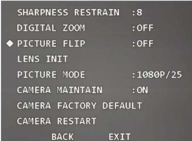
WB SETTING EXPOSURE SETTING DAY/NIGHT SETTING FOCUS SETTING IMAGE ADJUST DEFOG SETTING ZOOM SPEED :8 ◆ SHARPNESS :8 NEXT PAGE BACK EXITFigure 3-40 Set sharpness suppression
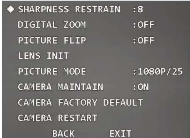
text_image
◆ SHARPNESS RESTRAIN :8 DIGITAL ZOOM :OFF PICTURE FLIP :OFF LENS INIT PICTURE MODE :1080P/25 CAMERA MAINTAIN :ON CAMERA FACTORY DEFAULT CAMERA RESTART BACK EXITStep 2 Click left and right buttons to set the value of sharpness suppression.
3.4.3.10 Setting Digital Zoom
Digital zoom refers to capturing a part of the image to magnify it. The higher the magnification is, the blurrier the images will become.
Step 1 Move the cursor to Digital Zoom.
Figure 3-41 Set digital zoom
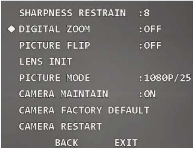
text_image
SHARPNESS RESTRAIN :8 ◆ DIGITAL ZOOM :OFF PICTURE FLIP :OFF LENS INIT PICTURE MODE :1080P/25 CAMERA MAINTAIN :ON CAMERA FACTORY DEFAULT CAMERA RESTART BACK EXITStep 2 Click left and right buttons select On or Off.
3.4.3.11 Setting Picture Flip
With the function, you can flip the monitoring image.
Step 1 Move the cursor to the Picture Flip.
Figure 3-42 Set picture flip
text_image
SHARPNESS RESTRAIN :8 DIGITAL ZOOM :OFF ◆ PICTURE FLIP :OFF LENS INIT PICTURE MODE :1080P/25 CAMERA MAINTAIN :ON CAMERA FACTORY DEFAULT CAMERA RESTART BACK EXITStep 2 Click left and right button to select On or Off.
3.4.3.12 Lens Initialization
Move the cursor to Lens Init, and then click Enter. The lens will be initialized.

You can try the function when the focus is not accurate, or the image is blurry.
Figure 3-43 Lens initialization

text_image
SHARPNESS RESTRAIN :8 DIGITAL ZOOM :OFF PICTURE FLIP :OFF ♦ LENS INIT PICTURE MODE :1080P/25 CAMERA MAINTAIN :ON CAMERA FACTORY DEFAULT CAMERA RESTART BACK EXIT3.4.3.13 Setting Picture Mode
You can set the image output mode, which includes 1080P/30, 1080P/25, 720P/25, 720P/30, 720P/50, and 720P/60. The XVR needs to support corresponding image mode to collect images.
Figure 3-44 Set picture mode

text_image
SHARPNESS RESTRAIN :8 DIGITAL ZOOM :OFF PICTURE FLIP :OFF LENS INIT ◆ PICTURE MODE :1080P/25 CAMERA MAINTAIN :ON CAMERA FACTORY DEFAULT CAMERA RESTART BACK EXITStep 2 Click left and right buttons to select the picture mode which needs to be output.
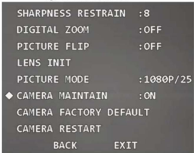
3.4.3.14 Setting Camera Maintenance
Move the cursor to Camera Maintain, and then click the left and right buttons to select On or Off.

If the function is enabled, the camera will restarts automatically after a period to perform maintenance.
Figure 3-45 Set camera maintenance
text_image
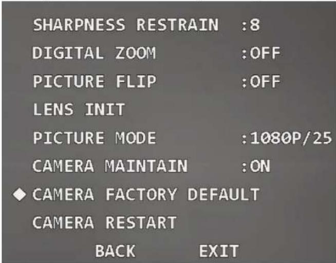
SHARPNESS RESTRAIN :8 DIGITAL ZOOM :OFF PICTURE FLIP :OFF LENS INIT PICTURE MODE :1080P/25 ♦ CAMERA MAINTAIN :ON CAMERA FACTORY DEFAULT CAMERA RESTART BACK EXIT3.4.3.15 Restoring the Camera to Factory Default Settings
If you perform the operation, all camera settings will be restored to factory default settings.
Figure 3-46 Restore the camera to factory default settings
text_image
SHARPNESS RESTRAIN :8 DIGITAL ZOOM :OFF PICTURE FLIP :OFF LENS INIT PICTURE MODE :1080P/25 CAMERA MAINTAIN :ON ◆ CAMERA FACTORY DEFAULT CAMERA RESTART BACK EXIT3.4.3.16 Restarting the Camera
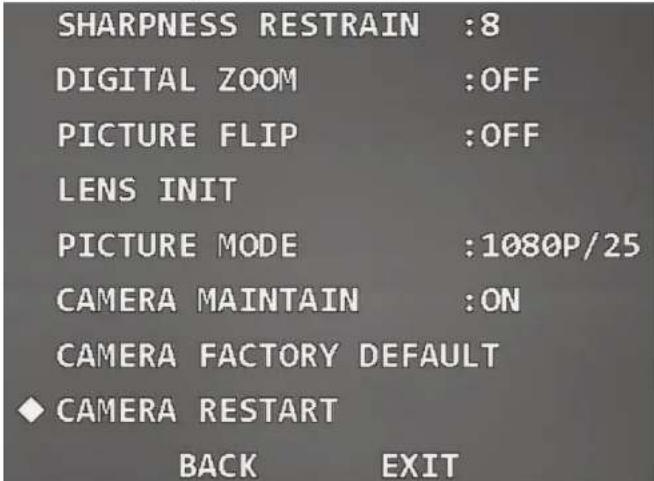
With the function, you can restart the camera, and some functions come effect only after you restart the camera.
Move the cursor to the Camera Restart, and then click Enter.
Figure 3-47 Restart the camera
text_image
SHARPNESS RESTRAIN :8 DIGITAL ZOOM :OFF PICTURE FLIP :OFF LENS INIT PICTURE MODE :1080P/25 CAMERA MAINTAIN :ON CAMERA FACTORY DEFAULT ♦ CAMERA RESTART BACK EXIT3.4.4 Function Settings
Move the cursor to Function Setting, and then click Enter to enter the second-level menu.
Figure 3-48 Function settings

text_image
PRESET AUTO PAN AUTO SCAN TOUR PATTERN IDLE MOTION AUTO RUN PRIVACY MASKING NEXT PAGE BACK EXIT[Non-Text]
The system automatically synchronizes the preset title according to the preset No. For example, if you set preset No. as 1, the title will be Preset1.
Step 3 Adjust the Device to the scene to be monitored.
[Non-Text]
You need to exit OSD menu, and then adjust the Device with PTZ control panel.
Step 4 Move the cursor to Setting, and then click Enter.
OK is displayed, and then disappears from the menu, which means the preset is set successfully.
[NO TEXT]
- If you have set Preset Title as On in Display Setting, when you call the preset on the live interface, the preset title will be displayed on the image.
- If you need to modify the preset, you can simply modify the preset No, adjust the monitoring scene, and then click Setting to overwrite the original preset.
Step 5 Call the preset.
- Move the cursor to Preset No to select the preset to be called.
- Move the cursor to Call, and then click Enter to call the preset.
[Non-Text]
If using PELCO protocol, you can call specific presets for some functions.
- Call preset
- Call Preset 28 or Preset 95 to enter the OSD menu.
◇ Call Preset 29 or Preset 99 to start scanning.
◇ Call Preset 24 or Preset 81 to start patterning.
◇ Call Preset 25 or Preset 82 to start tour. - Call Preset 30 or Preset 96 to stop scanning or tour.
◇ Call Preset 31 or Preset 83 to start pan.
◇ Call Preset 33 to enable 180° horizontal rotation.
Cell Project 24 to set device coordinates as 0
Figure 3-50 Set pan

text_image
PAN SPEED :5 RUN STOP BACK EXITStep 2 Click left and right buttons to set the pan speed.
Step 3 Move the cursor to Run, and then click Enter. The Device starts pan. Move the cursor to Stop, and then click Enter to stop pan.
3.4.4.3 Setting Scan
Scan means the Device moves horizontally at a certain speed between the defined left and right limits.
Step 1 Move the cursor to Auto Scan, and then click Enter to enter the third-level menu.
Figure 3-51 Set scan

text_image
♦ AUTO SCAN NO :1 SET LEFT LIMITStep 5 Go to the live interface, and then adjust the Device to the right limit of the required scan range.
Step 6 Move the cursor to the Set Right Limit, and then click Enter. OK is displayed if the setting is successful.
Step 7 Move the cursor to Scan Speed, and then click left and right buttons to select scan speed.
Step 8 Call the scan.
- Move the cursor to Auto Scan No, and then select the scan number to be called.
- Move the cursor to Call, and then click Enter. The system calls the scan. Move the cursor to Stop, and then click Enter. The scan stops.
3.4.4.4 Setting Tour
You can add some presets to a tour in the required sequence, and then call the tour to make the Device automatically moves back and forth among these presets at specified time intervals in the defined sequence.
Step 1 Move the cursor to Tour, and then click Enter to enter the third-level menu.
Figure 3-52 Set tour (1)

text_image
TOUR NO :1 SETTING DELETE CALLFigure 3-53 Set tour (2)
| NO | PRESET | DWELL | SPEED |
| 01 | 000 | 015 | 012 |
| 02 | 000 | 015 | 012 |
| 03 | 000 | 015 | 012 |
| 04 | 000 | 015 | 012 |
| 05 | 000 | 015 | 012 |
| 06 | 000 | 015 | 012 |
| 07 | 000 | 015 | 012 |
| 08 | 000 | 015 | 012 |
| BACK | EXIT |
Step 4 Set the preset No, dwell time and speed, and then click Enter to exit the setting.
Step 5 Call the tour.
1. Move the cursor to Tour No, and then select the tour No to be called.
2. Move the cursor to Call, and then click Enter. The system calls the tour. Move the cursor to Stop, and then click Enter. The tour stops.

You can click Delete to delete the tour.
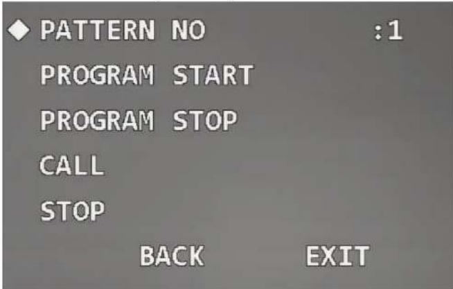
Figure 3-54 Set pattern
text_image
PATTERN NO :1 PROGRAM START PROGRAM STOP CALL STOP BACK EXITStep 2 Click left and right buttons to set pattern No.
Step 3 Move the cursor to Program Start, and then click Enter. OK is displayed, and the system starts recording the pattern path.
Step 4 Operate the Device as needed, move the cursor to Program Stop, and then click Enter. OK is displayed if the setting is successful.

If the time interval between two operations is over 1 minute, the system takes it as 1 minute by default.
Step 5 Call the pattern.
- Move the cursor to Pattern No, and then select the pattern No to be called.
- Move the cursor to Call, and then click Enter. The system calls the pattern. Move
Figure 3-55 Set idle motion

text_image
IDLE FUNCTION :OFF IDLE TIME :10MIN IDLE ACTION :NONE PARAMETER :NONE BACK EXITStep 2 Move the cursor to Idle Function, and then click left and right buttons to set it as On.
Step 3 Move the cursor to Idle Time, and then click left and right buttons to select the needed time.
Step 4 Move the cursor to Idle Action, and click left and right buttons to select motion type from None, Preset, Scan, Tour, and Pattern.
Step 5 Move the cursor to Parameter, and then click left and right buttons to select the number of the selected motion.
3.4.4.7 Setting Time Task
After setting time task, the Device performs the selected motions during the defined period.
Step 1 Move the cursor to Auto Run, and then click Enter to enter the third-level menu.
Figure 3-56 Set time task (1)

Figure 3-57 Set time task (2)
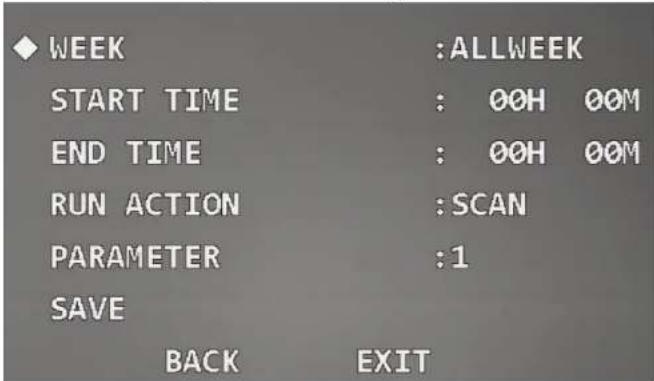
text_image
WEEK :ALLWEEK START TIME : 00H 00M END TIME : 00H 00M RUN ACTION :SCAN PARAMETER :1 SAVE BACK EXITStep 4 Click the direction buttons to set Week, Start Time, End Time, Run Action, and Parameter.
Step 5 Click Save.
After the setting is completed, Time Task status is changed to On automatically.

- Move the cursor to Task Information, and then click Enter to view the task that you have set.
Figure 3-58 Task information

text_image
NO TIME ACTION 1 ALL 03:00-00:00 SCA001Figure 3-59 Set privacy masking (1)

text_image
◆ PRIVACY NO :1 ACTIVATE :OFF SETTING BACK EXITStep 2 Click left and right buttons to set the privacy No.

The number of privacy masks and setting requirements vary with the models, and the actual product shall prevail.
Step 3 Move the cursor to Setting, and then click Enter to enter the fourth-level menu. A privacy mask is displayed at the center of the screen.
Figure 3-60 Set privacy masking (2)

text_image
◆ RESIZE : ↑ SAVE BACK EXIT- Click Enter continuously to adjust the privacy mask to the needed size.

Make the privacy mask larger than the object to be masked; otherwise the object might be exposed during device movement.
Step 6 Click Save to exit the setting interface.
The status of Activate is changed to On automatically.

Move the cursor to Privacy No, click left and right buttons to select the privacy mask No, and then click Enter. The image will be switched to this masked area.
3.4.4.9 Setting PTZ Speed
You can adjust the manual control speed of the PTZ by setting PTZ speed.
Move the cursor to PTZ Speed, and then click left and right buttons to select PTZ speed from 1, 2, and 3.
Figure 3-61 Set PTZ speed

text_image
PTZ SPEED :2 SET ZERO POWER UP MENU PASSWORD MENU TDLE :1MTNneeded.
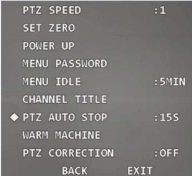
Step 1 Move the cursor to Set Zero.
Figure 3-62 Set zero
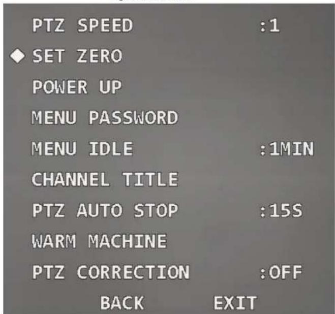
text_image
PTZ SPEED :1 SET ZERO POWER UP MENU PASSWORD MENU IDLE :1MIN CHANNEL TITLE PTZ AUTO STOP :15S WARM MACHINE PTZ CORRECTION :OFF BACK EXITStep 2 Adjust the Device to the location that you need to set as zero.
Tour, Pattern, and None.

If you select Auto, the last operation before you shut down the Device last time will be set as power up action.
Step 3 Move the cursor to Parameter, and then click left and right buttons to select the number of the corresponding operation.

To use the function, set preset, tour, scan or pattern in advance.
3.4.4.12 Setting Menu Password
After setting the menu password, you need to enter the correct password to open the menu.

The menu will be locked after three wrong attempts. In this case, contact after-sales service.
Step 1 Move the cursor to Menu Password, and click Enter to enter the third-level menu.
Figure 3-64 Set menu password (1)

text_image
◆ PASSWORD :OFF SETTING BACK EXITStep 2 Move the cursor to Setting, and then click Enter to enter the fourth-level menu.
Step 5 Click Enter to exit the setting interface. The password will be enabled automatically.
3.4.4.13 Setting Menu Idle
When the OSD menu is opened and the function is enabled, the menu disappears if there is no operation on the menu during the defined period. Move the cursor to Menu Idle, and then click left and right buttons to select the idle time.
Figure 3-66 Set menu idle
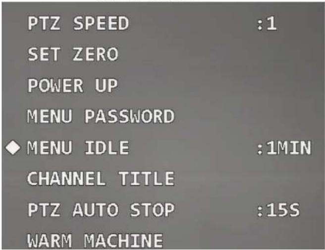
text_image
PTZ SPEED :1 SET ZERO POWER UP MENU PASSWORD ◆ MENU IDLE :1MIN CHANNEL TITLE PTZ AUTO STOP :15S WARM MACHINEFigure 3-67 Set channel title (1)

text_image
TITLE POSITION :LEFT UP SETTING BACK EXITStep 2 Click left and right buttons to set Title Position as Right Up, Left Down, Right Down, or Left Up.
Step 3 Move the cursor to Setting, and then click Enter to enter fourth-level menu.
Figure 3-68 Set channel title (2)

text_image
TITLE: ◆ Z ENTER BACKStep 4 Click up and down buttons to set channel title content, and then click Enter to move the cursor to the next digit.

The channel title consists of numbers (0–9), letters (A–Z), or their combination.
Step 5 Click Enter.
3.4.4.15 Setting PTZ Auto Stop
PTZ auto stop means that the Device will automatically stop PTZ operations if it does not
Figure 3-69 Set PTZ auto stop
text_image
PTZ SPEED :1 SET ZERO POWER UP MENU PASSWORD MENU IDLE :5MIN CHANNEL TITLE ◆ PTZ AUTO STOP :15S WARM MACHINE PTZ CORRECTION :OFF BACK EXITStep 2 Click left and right buttons to select the time period. You can select Off, 5S, 10S, 15S, 20S, 25S, or 30S.
3.4.4.16 Setting Temperature Control

Auto is selected by default.
Step 3 Move the cursor to Open Temperature, and then click left and right buttons to set the temperature value.
The heater is enabled automatically when the temperature is lower than the value.
Step 4 Move the cursor to Close Temperature, and then click left and right buttons to set the temperature value.
The heater is disabled automatically when the temperature is higher than the value.
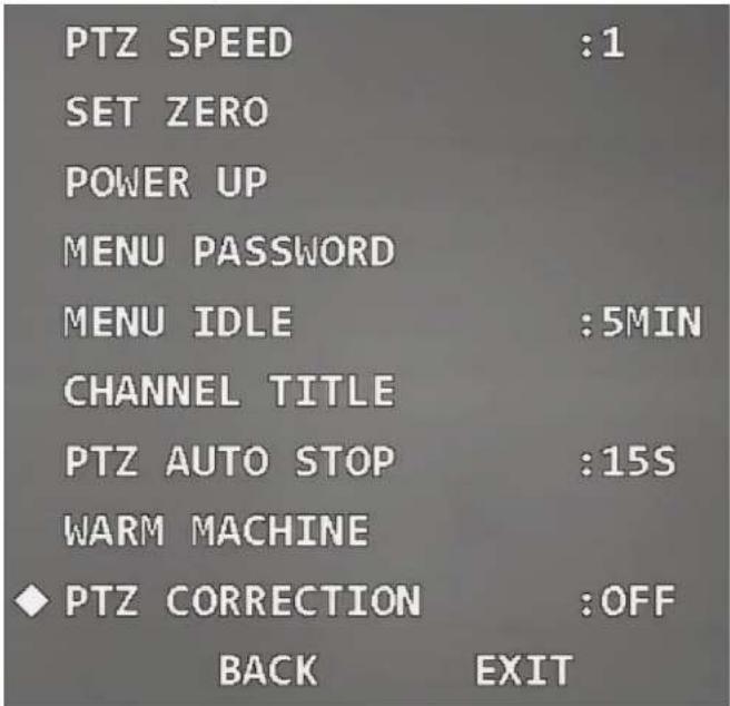
3.4.4.17 Setting PTZ Correction
When the PTZ comes to its service life, or there is mechanical failure or artificial damage, the vertical optocoupler might be damaged. In this case, the vertical optocoupler location can be adjusted automatically with the function.
Move the cursor to PTZ Correction, and then click left and right buttons to select On or Off.

The function takes effect only after you restart the Device.
Figure 3-71 Set PTZ correction
text_image
PTZ SPEED :1 SET ZERO POWER UP MENU PASSWORD MENU IDLE :5MIN CHANNEL TITLE PTZ AUTO STOP :15S WARM MACHINE ◆ PTZ CORRECTION :OFF BACK EXITFigure 3-72 Alarm settings

text_image
ALARM NO :1 ACTION :NONE PARAMETER :NONE CONTACT :N/O RELAY OUT :OFF RESET DELAY :3S SAVE BACK EXITStep 2 Move the cursor to Alarm No, and then click left and right buttons to select the channel number of alarm input.
Step 3 Move the cursor to Action, and then click left and right buttons to select linked actions from Preset, Scan, Tour, Pattern, and None.
Step 4 Move the cursor to Parameter, and then click left and right buttons to select the number of the corresponding linked action.
Step 5 Move the cursor to Contact, and then click left and right buttons to select the trigger mode of linked actions.
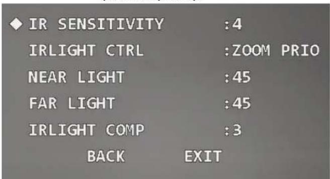
3.4.6 IR Light Settings

The function is available on select models, and the actual product shall prevail.
Step 1 Move the cursor to IR Light Setting, and then click Enter to enter the second-level menu.
Figure 3-73 IR light settings
text_image
IR SENSITIVITY :4 IRLIGHT CTRL :ZOOM PRIO NEAR LIGHT :45 FAR LIGHT :45 IRLIGHT COMP :3 BACK EXITStep 2 Move the cursor to IR Sensitivity, and then click left and right buttons to select IR light sensitivity.
Step 3 Move the cursor to IR Light Ctrl to select IR light control mode.
- Zoom priority mode
- Click left and right button to select Zoom Prio. The Device can automatically adjust IR light brightness according to the actual zoom rate.
- Move the cursor to IR Light Comp, and then click left and right buttons to set
4 Maintenance
4.1 Regular Cleaning
To ensure clear image, you need to clean the lens glass regularly.
- Handle the Device with care. Hold the dome with your hands, and avoid touching the glass surface with your fingers.
- Rinse the glass surface with clean water.
- Use mild detergent if there is too much dust.
4.2 Troubleshooting
Table 4-1 Troubleshooting
| Issue | Possible Reason | Solution |
| No self-test and no image after the Device is powered | Red LED light on the power board is off.The power supply is not connected to the power board or the connection is in bad contact.Mains electricity failure or transformer problem. | Check whether the power supply is properly connected.Check whether the mains electricity and transformer are working normally. |
| Use the multimeter to | ||
| Lens glass is dirty. | Clean the lens glass. |