O2TMLB8 - Security Camera Speco Technologies - Free user manual and instructions
Find the device manual for free O2TMLB8 Speco Technologies in PDF.

User questions about O2TMLB8 Speco Technologies
0 question about this device. Answer the ones you know or ask your own.
Ask a new question about this device
Download the instructions for your Security Camera in PDF format for free! Find your manual O2TMLB8 - Speco Technologies and take your electronic device back in hand. On this page are published all the documents necessary for the use of your device. O2TMLB8 by Speco Technologies.
USER MANUAL O2TMLB8 Speco Technologies
O2TMLB8 User's Manual
Network Camera Manual (O2TMLB8)

natural_image
Technical line drawing of a mechanical component with flanged ends and a cylindrical housing (no text or symbols)Directions
Be careful not to cause any physical damage by dropping or throwing the camera. Especially keep the device out of reach from children.
Do not disassemble the camera. No after service is assumed when disassembled.
Use only the power adapter provided with the camera.
Be careful to prevent moisture or water penetration into the unit. Attention is needed when installing the camera. The screw holes for the installation screws and pipe should be maintained water tight during the whole life time of the product.
All of the electrical connection wires running into the unit should be prepared so that water from the outside cannot flow into the unit through the surface of the wires. Penetration of moisture through the wire for an extended period can cause malfunction of the unit or deteriorated image.
Note
This equipment has been tested and found to comply with the limits for a Class A digital device pursuant to part 15 of the FCC Rules. These limits are designed to provide reasonable protection against harmful interference in a residential installation. This equipment generates, uses and can radiate radio frequency energy and, if not installed and used in accordance with the instructions, may cause harmful interference to radio communications. However, there is no guarantee that interference
Caution
Any changes or modifications in construction of this device which are not explicitly approved by the party responsible for compliance could void the warranty.
Revision History
| Date | Revision | Details |
| July 2, 2018 | 1.0 | First manual revision creation. |
Contents
Contents 4
- Introduction......5
1.1. Overview....5
1.2. Specifications....6
1.3. Applications of O2TMLB8....7
- Product Description....8
2.1.Contents 8
2.2. Product Preview....8
2.3. Physical description 9
2.4. Functional Description.... 11
- On Site Installation 13
3.1. Installation....13
- Getting Started 14
4.1. PC System Requirements....14
4.2. Quick Installation Guide ....15
- Troubleshooting....19
5.1. No power is applied....19
5.2. Cannot connect to the camera....20
5.3. Technical Assistance 21
1. Introduction
1.1. Overview
The O2TMLDB8 is a dual thermal, triple-codec (H.265, H.264, MJPEG) IP camera built with embedded software and hardware technology. It enables real time transmission of synchronized video and audio data. Remote clients can connect to the device for real time video/audio data through various client solutions running on PCs and smartphones. Real time 2-way communication is available through the bidirectional audio communication feature.
Intensifier® technology is an optimized solution for surveillance in low light conditions, achieved by using a superior CMOS sensor with an ISP for low light sensitivity. Intensifier® provides color image even in poor lighting conditions. In addition, this camera provides an embedded thermal picture-in-picture image to provide additional monitoring for temperature-related scenarios, where a normal camera image would not detect.
Designed to be a stand-alone streaming audio & video transmission device, this camera can be applied to various applications such as video security, remote video monitoring, remote education, video conference or internet broadcasting system.
Integrated PoE (Power over Ethernet, IEEE 802.3af) will reduce the total cost of ownership by reducing on-site wiring for installation.
1.2. Specifications
| Model No. | O2TMLB8 | |
| Image Sensor | 80x60 | 2MP(1920x1080) |
| Video | ||
| Pixel Pitch | 17um | - |
| Spectral Range | 8um to 14um | - |
| Thermal Sensitivity of Detector(NETD) | <50mk | - |
| Accuracy | High gain: ±5°C or 5%Low gain: ±10°C or 10% | - |
| Max. Resolution | 80x60 | 1920x1080 |
| Scanning Mode | Progressive Scan | Progressive Scan |
| Lens | 4mm | |
| IRIS Control | Fixed | Fixed |
| Angular Field of View | 51°(H) * 38°(V) * 63.5°(D) | 79.6°(H) * 42.4°(V) * 94.3°(D) |
| S/N Ratio | - | more than 40dB |
| Dynamic Range | - | 108dB (true WDR) |
| Electronic Shutter Speed | - | Auto / Manual (1/30(25) ~ 1/10,000), Anti-Flicker, Slow Shutter(Off,1/15 sec~1/1 sec) |
| Video Quality | Auto Expose, Auto White Balance, 3D Digital Noise | |
| IP Camera Protocol | ONVIF Profile S | |
| supports Resolution | 80x60 | 352X240, 640X360, 704X480, 1280x720, 1920x1080, Pivot |
| Multi-Video Streaming | Triple streaming | |
| Network Protocols | RTP/RTSP/TCP, RTP/RTSP/HTTP/TCP, RTP/UDP RTSP/TCP, HTTP, HTTPS, FTP, SNTP, SMTP, FEN, mDNS, Upnp | |
| Security | Multi-User Authority, IEEE 802.1x IP Filtering, HTTPS, SSL Encryption | |
| Ethernet | RJ45(10/100BASE-T) | |
| Edge Storage | Yes(Micro SD Card) | |
| Alarm & Event | ||
| Trigger Event | Motion Detection, Tampering, TrlpZone, Temperature Event | |
| Event Buffering (Pre & Post) | yes (up to 60MB) | |
| Event Notification | Remote S/W, Email (with Image) | |
| Audio In/ Out | Yes | |
| Alarm In/ Out | Yes | |
| Environmental | ||
| Out-door Ready | IP66 | |
| Operating Temperature | -20°C ~ 50°C | |
| Operating Humidity | 0% ~ 90% | |
| General | ||
2. Product Description
2.1. Contents
The product package contains the following:
| Contents | Description | Image | Remarks |
| Main Unit | O2TMLB8 |  | |
| Tools and Mounting Screws | Screw-MS 4EA, Screw-TAP 4EA, Plastic Anchor 4EA, Junction box |  | |
| CD | Software & User's Guide |  | |
| Quick Reference Guide | Quick installation guide |  | |
| GPL License | Open Source Guide | [8GS8] |
2.2. Product Preview
O2TMLB8 User's Manual
2.3. Physical description
2.3.1. External View
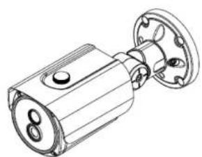
natural_image
Technical line drawing of a mechanical component with flanged ends and a cylindrical shaft (no text or symbols)Figure 2-1. External view of O2TMLB8
2.3.2. Dimensions

text_image
8.32 3.54 8.11 9.20O2TMLB8 User's Manual
flowchart
graph TD
    A["①"] --> B["②"]
    B --> C["③"]
    C --> D["④"]
    D --> E["⑤"]
    E --> F["⑥"]
    style A fill:#f9f,stroke:#333
    style B fill:#ccf,stroke:#333
    style C fill:#cfc,stroke:#333
    style D fill:#fcc,stroke:#333
    style E fill:#cff,stroke:#333
    style F fill:#ffc,stroke:#333
    linkStyle 0 stroke:#000,stroke-width:2px
    linkStyle 1 stroke:#000,stroke-width:2px
    linkStyle 2 stroke:#000,stroke-width:2px
    linkStyle 3 stroke:#000,stroke-width:2px
    linkStyle 4 stroke:#000,stroke-width:2px
    linkStyle 5 stroke:#000,stroke-width:2px
    linkStyle 6 stroke:#000,stroke-width:2px
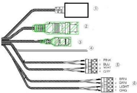
- Network Port 2. BNC Video Out 3. Power In
- Ground 5. Audio In/Out 6. Alarm In/Out
Figure 2-3. Connector information
2.4. Functional Description
• Power
Power input for supplying 12V 1A DC power.

Caution: If the camera is powered by PoE, do not plug in DC Jack with active DC power into DC power jack.
• Audio (MIC/LINE) IN
Connect external audio source or microphone.
• Audio (Line) In
Connect speakers with built in amplifier. Audio from remote site is output through Line out in bi-directional audio mode.
• RJ-45 Ethernet (100Base-T) / PoE (IEEE802.3af)
100Mbps Ethernet connector (RJ-45) with standard PoE (802.3af).
- SENSOR IN
Connect external alarm sensor. Examples of sensing devices are infrared sensor, motion sensor, heat/smoke sensor, magnetic sensor, etc. Connect the two wires of the sensors to "Sensor In". The sensor type (NC/NO) can be set in the setup page. Multiple sensor devices can be connected in parallel.
O2TMLB8 User's Manual
• Factory Default Switch
A switch provided for returning the IP camera to factory default state. Unscrew the cover to access the switch. Press the switch for 5 seconds while power is applied.

natural_image
Technical line drawing of a mechanical component with concentric circles and mounting holes (no text or symbols)Factory default switch
Figure 2-5. Factory Default Switch
3. On Site Installation
Use cables and conduits that are suitable for the installation. Close attention should be paid to the installation so that no moisture is allowed to penetrate into the unit through the cables or conduits during the lifetime of the product. Products that have internal parts exposed to moisture due to improper installation are not covered by warranty.
3.1. Installation
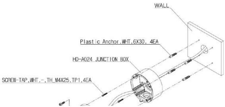
text_image
WALL Plastic Anchor, WHT, 6X30, 4EA HD-A024 JUNCTION BOX SCREW-TAP, WHT, -, TH_M4X25, TP1, 4EA- Apply power.
WARNING: You might need to reinforce the wall or ceiling. If the wall or ceiling is not strong enough to support the camera, the camera might fall damaging the camera or causing injuries.
4. Getting Started
Brief information for the initial operation of the camera is provided in this chapter.
4.1. PC System Requirements
Audio/Video streaming data received from O2TMLB8 can be displayed or stored in a PC running client programs. Minimum requirements of the PC are described below:
| Minimum Requirements | Recommended Specifications | |
| CPU | Intel Core i3 | Intel Core i5 |
| Main Memory | 2GB | 4GB |
| Operating System* | Windows XP | Windows 7,8 (64bit) or higher |
4.2. Quick Installation Guide
- Connect PC and O2TMLB8 to a network.
1) Prepare a PC to run programs for the installation and video connection
2) In the case of using PoE, connect the PC and O2TMLB8 to the network using one of the following ways. If your LAN Switch does not support standard PoE, connect O2TMLB8 as shown in dotted line in Figure 4-1. The DC power is applied through DC adapter.
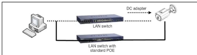
flowchart
graph LR
    A["Computer"] --> B["LAN switch"]
    B --> C["DC adapter"]
    B --> D["LAN switch with standard POE"]
    D --> C
Figure 4-1. Power and network connection
2. Install IP Scanner
IP Scanner is a utility to discover IP cameras on the local network. The camera is set to DHCP mode out of the box.
Follow the sequence below to access the camera settings
i) Install IP Scanner on the PC that will be used on the same local network as the IP camera. IP Scanner can be found on the CD included in the package or downloaded from specotech.com.
ii) Run IP Scanner
iii) The available cameras on the local network will show automatically
iv) Highlight and double-click on the applicable model to launch the camera web viewer (default browser must be set to Internet Explorer to view video)
| Refresh | Open Web Page | Login... | IP | Restart | Factory Default | Information | About |
| Status | Name | IP Address | MAC Address | Version | |||
| Online | O2D7M | 192.168.56.169 | 00:03:22:1E:97:8A | ||||
| Online | O2DP8M | 192.168.56.163 | 00:03:22:1E:97:6B | 1.0.0 | |||
| Online | O2MB1 | 192.168.56.17 | 00:07:18:FF:01:C9 | 1.0.59 | |||
| Online | O2D4 | 192.168.56.124 | SC:F2:07:1C:28:CA | 1.0.53 | |||
| Online | VIP2PTZ12X | 192.168.56.52 | 00:07:D8:17:8A:68 | 1.3.7-X1_release | |||
| Online | OSMDP1 | 192.168.56.146 | SC:F2:07:1C:23:D8 | 1.0.47 | |||
| Online | Eddie-O2DP8 | 192.168.56.129 | SC:F2:07:1C:1F:74 | 1.0.51 | |||
| Online | SID-O2PTZ34D5W-... | 192.168.123.119 | SC:F2:07:1C:15:68 | 1.0.41 | |||
| Online | OPTZ36XI | 192.168.56.140 | SC:F2:07:1C:03:1D |
3. Remote video connection to O2TMLB8
1) Connection through Web Viewer
The web viewer offers the simplest way to connect to the O2TMLB8. For video connection, enter the IP address of O2TMLB8 in the Internet Explorer address bar as:
[e.g.] Port 80
http://172.16.64.133/
Port 80 (default) can be omitted
[e.g.] Port 8080
http://172.16.64.133:8080/

Note : When prompted, install and allow the Active X controls as needed
speco technologies

O2TMLB8 User's Manual

text_image
Screenshot of a software interface showing tool panels and a document with Chinese text, likely from a software development or design tool.5. Troubleshooting
5.1. No power is applied
● In case of Standard PoE (Power over Ethernet)
Power supply through standard PoE is possible only when the following conditions are met.
- Standard PoE is supported on the product.
- The LAN switch supports standard PoE.
Make sure that both the IP camera and the LAN switch support standard PoE (IEEE 802.3af)
● In case of DC adapter
If PoE is not applied, the power and network connection should be made through separate cables. Use the DC adapter recommended by the provider. In case of replacing the DC power supply, make sure that the power supply meets the power requirement of the IP camera to prevent damage or malfunction.
5.2. Cannot connect to the camera
Check the status of the network connection through PING test.
Try the following on your PC:
- Start > Run > Cmd > Ping IP address (Ex : Ping 172.16.42.51)
- If "Reply from \~" message is returned (① in the figure below), the network connection is in normal state. Try connection to the video again. If the problem persists, or refer to other trouble shooting notes.
- If "Request timed out" message is returned. (② in the figure below), the network connection or network setting is not in normal state. Check the network cable and settings.

text_image
C:\WINDOWS\system32\cmd.exe Microsoft Windows XP (Version 5.1.2600) (C) Copyright 1985-2001 Microsoft Corp. C:\Documents and Settings\ouperman>ping 172.16.42.51 Pinging 172.16.42.51 with 32 bytes of data: Reply from 172.16.42.51: bytes=32 time(1ms TTL=64) Reply from 172.16.42.51: bytes=32 time(1ms TTL=64) Reply from 172.16.42.51: bytes=32 time(1ms TTL=64) Reply from 172.16.42.51: bytes=32 time(1ms TTL=64) Ping statistics for 172.16.42.51: Packets: Sent = 4, Received = 4, Lost = 0 (Rx loss). Approximate round trip times in milli-seconds: Minimum = One, Maximum = One, Average = One C:\Documents and Settings\ouperman>5.3. Technical Assistance
If you need any technical assistance, please contact Speco's technical support. Please provide the following information.

- Model name
- MAC address
- Purchase date
- Description of the problem
- Error message